EP3549664A1 - Procédé et dispositif pour la sonication d'un échantillon biologique - Google Patents
Procédé et dispositif pour la sonication d'un échantillon biologique Download PDFInfo
- Publication number
- EP3549664A1 EP3549664A1 EP18165846.9A EP18165846A EP3549664A1 EP 3549664 A1 EP3549664 A1 EP 3549664A1 EP 18165846 A EP18165846 A EP 18165846A EP 3549664 A1 EP3549664 A1 EP 3549664A1
- Authority
- EP
- European Patent Office
- Prior art keywords
- sample tube
- tube holder
- sample
- sonicating
- sonotrode
- Prior art date
- Legal status (The legal status is an assumption and is not a legal conclusion. Google has not performed a legal analysis and makes no representation as to the accuracy of the status listed.)
- Pending
Links
- 239000012472 biological sample Substances 0.000 title claims abstract description 29
- 238000000034 method Methods 0.000 title claims abstract description 17
- 239000000523 sample Substances 0.000 claims abstract description 209
- 238000000527 sonication Methods 0.000 claims abstract description 68
- 238000002604 ultrasonography Methods 0.000 claims description 10
- 230000005484 gravity Effects 0.000 claims description 5
- 239000012620 biological material Substances 0.000 description 10
- 239000007788 liquid Substances 0.000 description 10
- 239000003153 chemical reaction reagent Substances 0.000 description 7
- 238000013523 data management Methods 0.000 description 6
- 108020004414 DNA Proteins 0.000 description 5
- 238000013459 approach Methods 0.000 description 5
- 230000005540 biological transmission Effects 0.000 description 5
- 108020004707 nucleic acids Proteins 0.000 description 5
- 102000039446 nucleic acids Human genes 0.000 description 5
- 150000007523 nucleic acids Chemical class 0.000 description 5
- 244000052769 pathogen Species 0.000 description 5
- 230000008901 benefit Effects 0.000 description 4
- 210000004027 cell Anatomy 0.000 description 4
- 239000012530 fluid Substances 0.000 description 4
- 238000012546 transfer Methods 0.000 description 4
- 239000012491 analyte Substances 0.000 description 3
- 230000009089 cytolysis Effects 0.000 description 3
- 230000007246 mechanism Effects 0.000 description 3
- 230000008569 process Effects 0.000 description 3
- 238000012545 processing Methods 0.000 description 3
- 239000013077 target material Substances 0.000 description 3
- 241000894006 Bacteria Species 0.000 description 2
- 241001302239 Mycobacterium tuberculosis complex Species 0.000 description 2
- 241000700605 Viruses Species 0.000 description 2
- 230000001580 bacterial effect Effects 0.000 description 2
- 239000008280 blood Substances 0.000 description 2
- 210000004369 blood Anatomy 0.000 description 2
- 238000006243 chemical reaction Methods 0.000 description 2
- 238000011109 contamination Methods 0.000 description 2
- 230000008878 coupling Effects 0.000 description 2
- 238000010168 coupling process Methods 0.000 description 2
- 238000005859 coupling reaction Methods 0.000 description 2
- 239000013078 crystal Substances 0.000 description 2
- 238000007865 diluting Methods 0.000 description 2
- 238000004519 manufacturing process Methods 0.000 description 2
- 239000002184 metal Substances 0.000 description 2
- 239000000203 mixture Substances 0.000 description 2
- 239000002245 particle Substances 0.000 description 2
- 230000001717 pathogenic effect Effects 0.000 description 2
- 102000004169 proteins and genes Human genes 0.000 description 2
- 239000007787 solid Substances 0.000 description 2
- 241000894007 species Species 0.000 description 2
- 230000003612 virological effect Effects 0.000 description 2
- XLYOFNOQVPJJNP-UHFFFAOYSA-N water Substances O XLYOFNOQVPJJNP-UHFFFAOYSA-N 0.000 description 2
- 206010003445 Ascites Diseases 0.000 description 1
- 108091005461 Nucleic proteins Proteins 0.000 description 1
- 206010036790 Productive cough Diseases 0.000 description 1
- 108020005202 Viral DNA Proteins 0.000 description 1
- 238000005299 abrasion Methods 0.000 description 1
- 210000004381 amniotic fluid Anatomy 0.000 description 1
- 239000000427 antigen Substances 0.000 description 1
- 108091007433 antigens Proteins 0.000 description 1
- 102000036639 antigens Human genes 0.000 description 1
- 210000003567 ascitic fluid Anatomy 0.000 description 1
- 238000003556 assay Methods 0.000 description 1
- 238000004166 bioassay Methods 0.000 description 1
- 238000010256 biochemical assay Methods 0.000 description 1
- 210000002421 cell wall Anatomy 0.000 description 1
- 210000001175 cerebrospinal fluid Anatomy 0.000 description 1
- 210000004748 cultured cell Anatomy 0.000 description 1
- 238000001514 detection method Methods 0.000 description 1
- 230000003292 diminished effect Effects 0.000 description 1
- 238000004821 distillation Methods 0.000 description 1
- 230000000694 effects Effects 0.000 description 1
- 210000003527 eukaryotic cell Anatomy 0.000 description 1
- 238000001914 filtration Methods 0.000 description 1
- 239000011888 foil Substances 0.000 description 1
- 238000000338 in vitro Methods 0.000 description 1
- 230000002779 inactivation Effects 0.000 description 1
- 230000001939 inductive effect Effects 0.000 description 1
- 230000003993 interaction Effects 0.000 description 1
- 230000002452 interceptive effect Effects 0.000 description 1
- 239000000463 material Substances 0.000 description 1
- 238000005259 measurement Methods 0.000 description 1
- 239000008267 milk Substances 0.000 description 1
- 210000004080 milk Anatomy 0.000 description 1
- 235000013336 milk Nutrition 0.000 description 1
- 239000013612 plasmid Substances 0.000 description 1
- 238000002360 preparation method Methods 0.000 description 1
- 238000011112 process operation Methods 0.000 description 1
- 210000001236 prokaryotic cell Anatomy 0.000 description 1
- 108090000623 proteins and genes Proteins 0.000 description 1
- 210000003296 saliva Anatomy 0.000 description 1
- 238000007789 sealing Methods 0.000 description 1
- 210000000582 semen Anatomy 0.000 description 1
- 210000003802 sputum Anatomy 0.000 description 1
- 208000024794 sputum Diseases 0.000 description 1
- 210000004243 sweat Anatomy 0.000 description 1
- 210000001179 synovial fluid Anatomy 0.000 description 1
- 238000012360 testing method Methods 0.000 description 1
- 238000009210 therapy by ultrasound Methods 0.000 description 1
- 210000001519 tissue Anatomy 0.000 description 1
- 230000001131 transforming effect Effects 0.000 description 1
- 230000032258 transport Effects 0.000 description 1
- 238000002525 ultrasonication Methods 0.000 description 1
- 210000002700 urine Anatomy 0.000 description 1
- 239000008207 working material Substances 0.000 description 1
Images


Classifications
-
- B—PERFORMING OPERATIONS; TRANSPORTING
- B01—PHYSICAL OR CHEMICAL PROCESSES OR APPARATUS IN GENERAL
- B01F—MIXING, e.g. DISSOLVING, EMULSIFYING OR DISPERSING
- B01F31/00—Mixers with shaking, oscillating, or vibrating mechanisms
- B01F31/80—Mixing by means of high-frequency vibrations above one kHz, e.g. ultrasonic vibrations
-
- C—CHEMISTRY; METALLURGY
- C12—BIOCHEMISTRY; BEER; SPIRITS; WINE; VINEGAR; MICROBIOLOGY; ENZYMOLOGY; MUTATION OR GENETIC ENGINEERING
- C12M—APPARATUS FOR ENZYMOLOGY OR MICROBIOLOGY; APPARATUS FOR CULTURING MICROORGANISMS FOR PRODUCING BIOMASS, FOR GROWING CELLS OR FOR OBTAINING FERMENTATION OR METABOLIC PRODUCTS, i.e. BIOREACTORS OR FERMENTERS
- C12M35/00—Means for application of stress for stimulating the growth of microorganisms or the generation of fermentation or metabolic products; Means for electroporation or cell fusion
- C12M35/04—Mechanical means, e.g. sonic waves, stretching forces, pressure or shear stimuli
-
- B—PERFORMING OPERATIONS; TRANSPORTING
- B01—PHYSICAL OR CHEMICAL PROCESSES OR APPARATUS IN GENERAL
- B01J—CHEMICAL OR PHYSICAL PROCESSES, e.g. CATALYSIS OR COLLOID CHEMISTRY; THEIR RELEVANT APPARATUS
- B01J19/00—Chemical, physical or physico-chemical processes in general; Their relevant apparatus
- B01J19/08—Processes employing the direct application of electric or wave energy, or particle radiation; Apparatus therefor
- B01J19/10—Processes employing the direct application of electric or wave energy, or particle radiation; Apparatus therefor employing sonic or ultrasonic vibrations
-
- B—PERFORMING OPERATIONS; TRANSPORTING
- B01—PHYSICAL OR CHEMICAL PROCESSES OR APPARATUS IN GENERAL
- B01F—MIXING, e.g. DISSOLVING, EMULSIFYING OR DISPERSING
- B01F35/00—Accessories for mixers; Auxiliary operations or auxiliary devices; Parts or details of general application
- B01F35/40—Mounting or supporting mixing devices or receptacles; Clamping or holding arrangements therefor
- B01F35/42—Clamping or holding arrangements for mounting receptacles on mixing devices
-
- C—CHEMISTRY; METALLURGY
- C12—BIOCHEMISTRY; BEER; SPIRITS; WINE; VINEGAR; MICROBIOLOGY; ENZYMOLOGY; MUTATION OR GENETIC ENGINEERING
- C12N—MICROORGANISMS OR ENZYMES; COMPOSITIONS THEREOF; PROPAGATING, PRESERVING, OR MAINTAINING MICROORGANISMS; MUTATION OR GENETIC ENGINEERING; CULTURE MEDIA
- C12N13/00—Treatment of microorganisms or enzymes with electrical or wave energy, e.g. magnetism, sonic waves
-
- C—CHEMISTRY; METALLURGY
- C12—BIOCHEMISTRY; BEER; SPIRITS; WINE; VINEGAR; MICROBIOLOGY; ENZYMOLOGY; MUTATION OR GENETIC ENGINEERING
- C12N—MICROORGANISMS OR ENZYMES; COMPOSITIONS THEREOF; PROPAGATING, PRESERVING, OR MAINTAINING MICROORGANISMS; MUTATION OR GENETIC ENGINEERING; CULTURE MEDIA
- C12N15/00—Mutation or genetic engineering; DNA or RNA concerning genetic engineering, vectors, e.g. plasmids, or their isolation, preparation or purification; Use of hosts therefor
- C12N15/01—Preparation of mutants without inserting foreign genetic material therein; Screening processes therefor
-
- G—PHYSICS
- G01—MEASURING; TESTING
- G01N—INVESTIGATING OR ANALYSING MATERIALS BY DETERMINING THEIR CHEMICAL OR PHYSICAL PROPERTIES
- G01N1/00—Sampling; Preparing specimens for investigation
- G01N1/28—Preparing specimens for investigation including physical details of (bio-)chemical methods covered elsewhere, e.g. G01N33/50, C12Q
- G01N1/286—Preparing specimens for investigation including physical details of (bio-)chemical methods covered elsewhere, e.g. G01N33/50, C12Q involving mechanical work, e.g. chopping, disintegrating, compacting, homogenising
-
- G—PHYSICS
- G01—MEASURING; TESTING
- G01N—INVESTIGATING OR ANALYSING MATERIALS BY DETERMINING THEIR CHEMICAL OR PHYSICAL PROPERTIES
- G01N1/00—Sampling; Preparing specimens for investigation
- G01N1/28—Preparing specimens for investigation including physical details of (bio-)chemical methods covered elsewhere, e.g. G01N33/50, C12Q
- G01N1/38—Diluting, dispersing or mixing samples
-
- B—PERFORMING OPERATIONS; TRANSPORTING
- B01—PHYSICAL OR CHEMICAL PROCESSES OR APPARATUS IN GENERAL
- B01F—MIXING, e.g. DISSOLVING, EMULSIFYING OR DISPERSING
- B01F2101/00—Mixing characterised by the nature of the mixed materials or by the application field
- B01F2101/23—Mixing of laboratory samples e.g. in preparation of analysing or testing properties of materials
-
- B—PERFORMING OPERATIONS; TRANSPORTING
- B06—GENERATING OR TRANSMITTING MECHANICAL VIBRATIONS IN GENERAL
- B06B—METHODS OR APPARATUS FOR GENERATING OR TRANSMITTING MECHANICAL VIBRATIONS OF INFRASONIC, SONIC, OR ULTRASONIC FREQUENCY, e.g. FOR PERFORMING MECHANICAL WORK IN GENERAL
- B06B1/00—Methods or apparatus for generating mechanical vibrations of infrasonic, sonic, or ultrasonic frequency
- B06B1/02—Methods or apparatus for generating mechanical vibrations of infrasonic, sonic, or ultrasonic frequency making use of electrical energy
- B06B1/06—Methods or apparatus for generating mechanical vibrations of infrasonic, sonic, or ultrasonic frequency making use of electrical energy operating with piezoelectric effect or with electrostriction
- B06B1/0607—Methods or apparatus for generating mechanical vibrations of infrasonic, sonic, or ultrasonic frequency making use of electrical energy operating with piezoelectric effect or with electrostriction using multiple elements
- B06B1/0611—Methods or apparatus for generating mechanical vibrations of infrasonic, sonic, or ultrasonic frequency making use of electrical energy operating with piezoelectric effect or with electrostriction using multiple elements in a pile
-
- G—PHYSICS
- G01—MEASURING; TESTING
- G01N—INVESTIGATING OR ANALYSING MATERIALS BY DETERMINING THEIR CHEMICAL OR PHYSICAL PROPERTIES
- G01N1/00—Sampling; Preparing specimens for investigation
- G01N1/28—Preparing specimens for investigation including physical details of (bio-)chemical methods covered elsewhere, e.g. G01N33/50, C12Q
- G01N1/286—Preparing specimens for investigation including physical details of (bio-)chemical methods covered elsewhere, e.g. G01N33/50, C12Q involving mechanical work, e.g. chopping, disintegrating, compacting, homogenising
- G01N2001/2866—Grinding or homogeneising
-
- G—PHYSICS
- G01—MEASURING; TESTING
- G01N—INVESTIGATING OR ANALYSING MATERIALS BY DETERMINING THEIR CHEMICAL OR PHYSICAL PROPERTIES
- G01N1/00—Sampling; Preparing specimens for investigation
- G01N1/28—Preparing specimens for investigation including physical details of (bio-)chemical methods covered elsewhere, e.g. G01N33/50, C12Q
- G01N1/38—Diluting, dispersing or mixing samples
- G01N2001/386—Other diluting or mixing processes
Definitions
- the present invention belongs to the field of analytical systems for conducting biological or biochemical assays. Within this field, it relates to processing of a liquid biological sample, such as a sample containing biomolecules, with the aid of ultrasonic treatment.
- access of the analytical reagents to a specific analyte within that pathogen may be achieved by a typical preparation step in which viral particles or bacterial cells are lysed such that the respective contents are released, before further measures for the enrichment of the analyte in question may be applied.
- Standard lysis procedures for most of the common viral particles and bacterial cells are well-stablished and known to the person of skill in the art.
- MTBC Mycobacterium tuberculosis complex
- Samples suspected to contain mycobacteria - or other challenging biological material - may be pre-treated by the application of ultrasound, also referred to as sonication or ultrasonication.
- ultrasound also referred to as sonication or ultrasonication.
- the approach is generally known and established in the art.
- Some approaches in the art rely on sonication while the respective sample vessel is submersed in a liquid medium, often simply water. In that case, the water actually transports the vibration caused by the ultrasonic waves to the sample vessel and thus the sample within, wherein a portion of the primary kinetic energy is usually lost as heat.
- a more efficient approach involves the direct transfer of ultrasonic energy through physical contact between a sonotrode and the respective vessel.
- the energy transfer may be impeded if the contact area between the sonotrode and the wall of the sample vessel is not optimal.
- Pertinent approaches applied in the art include, for example, US 6,686,195 , disclosing a weight controlling the degree of coupling between a sonotrode and a sample vessel.
- the surfaces of sample vessels are usually not ideally even, but exhibit certain material- and/or production-based tolerances that can reduce the effective physical coupling and thus the transmission of ultrasonic energy.
- the present disclosure describes an approach that avoids such shortcomings in the art.
- a device for sonicating a biological sample contained in a sample tube.
- the device includes at least a sample tube holder, a sonotrode, and an actuator.
- the sample tube holder is flexibly suspended from a pivot engaged to a mount within the sonication device.
- the pivot allows for the tube holder to rotate about an x-axis in vertical direction.
- the tube holder is not rotationally deflected, it holds the respective sample tube in a vertical orientation along a z-axis essentially following the direction of gravity and being perpendicular to the x-axis, such that the tube and the sample within are held substantially upright.
- the vessel holder has an opening to at least one side to allow for physical contact between the tube and the sonotrode.
- the latter includes a sonication area through which the ultrasound is transmitted to the sample tube upon contacting its side wall.
- the sonotrode and the sample holder are aligned such that the vertical center of the sonication area - along the z-axis - is on the same height as the rotational pivot point - represented by the x-axis - about which the sample tube holder is rotatable.
- the sonotrode is mounted on a guiding rail such that it can be moved with the aid of the actuator towards or away from the sample holder following a y-axis. The latter is perpendicular to both the x-axis and the z-axis.
- the sonicating area can be brought into contact with the side wall of the sample tube through the respective opening in the sample tube holder.
- Guidance of this movement is improved by the guiding rail being fixed at one end to the mount for the sample tube holder.
- a rotational movement of the sample tube and thus the sample tube holder may be induced by the contact of the sonicating area by applying a pre-defined force to the sample holder via the sonotrode, if due to unevenness of the tube wall surface a portion of the tube wall comes into contact with the sonicating area prior to the tube wall's other portions, thus optimizing the actual contact area and thereby the transmission of ultrasound.
- a method for sonicating a biological sample contained in a sample tube using the device described above is disclosed herein.
- a first aspect described herein is a sonication device for sonicating a biological sample contained in a sample tube, the sonication device comprising:
- This sonication device enables the skilled person to optimize the transmission of ultrasonic energy from the sonotrode to the biological sample in the respective sample tube and thereby efficiently treat it, such as, for instance, to lyse robust pathogens like mycobacteria and release their biochemical contents such as nucleic acids.
- the contact area between the sonicating area may be reduced as previously mentioned, such that the energy transfer to the tube and thus the biological sample therein may be hampered.
- the sample tube which is, in the absence of a rotational movement of the sample tube holder, held essentially vertically along the z-axis, may have a slightly uneven or warped surface.
- the tube may in some embodiments have a tapered shape towards its top or, more often, its bottom.
- the tube may in some embodiments have a conical shape.
- the side wall of the sample tube may not form an ideal plane surface. More precisely, along the vertical dimension of the sample tube wall to be contacted with the sonicating area, certain portions of the surface may protrude in relation to other portions. In the case of a rigidly mounted sample tube holder, the sonicating area would be pressed against the tube wall upon moving the sonotrode to the sample tube holder without the possibility to adapt location or orientation. In the case of lesser applied force, the sonicating area would touch the tube wall only at its protruding portion(s), resulting in a non-optimal contact area and the related loss of energy transmission.
- the sonotrode may deform the tube, which may endanger the integrity of the sample tube.
- the latter case may even lead to loss of the sample material, including contamination of the sonication device and posing security risks to the operating personnel in case the biological sample indeed contains pathogens.
- the sonication device described herein avoids these risks by providing geometrical flexibility for optimizing the contact area between the side wall of the sample tube and the sonicating area. More precisely, in the above-described case, a sonotrode being pressed against the side wall with a pre-defined force would not cause the sample tube holder to remain in the conformation leading to a diminished contact area, but the sample tube holder could rotate around the x-axis defined by the pivot point of the pivot upon contact of the tube wall with the sonication area of the sonotrode. For instance, if the tube has a tapered shape towards its bottom and is held vertically within the sample tube holder, then a vertical, substantially even sonicating area would usually first contact the upper portion of the tube wall.
- the tube Upon application of a pre-defined force to the tube wall from the actuator via the sonotrode, the tube can now initiate a rotational movement in which its contacted upper portion follows the movement of the sonotrode, while the lower - so far not contacted - portion is rotated towards the sonicating area opposite to the movement of the sonotrode, since the vertical center of the sonicating area and the pivot point represented by the x-axis are mounted on substantially the same height.
- the upper portion of the side wall will remain in physical contact with the sonicating area, while the lower portion - previously not in contact - will be rotated towards the sonicating area and touch it, thereby optimizing the possible contact area between the tube wall and the sonicating area.
- the "sonication position" both the rotational movement of the sample tube holder and the translational movement of the sonotrode have reached an arresting point, such that the optimized contact area is maintained for and throughout the sonication process, as long as the force applied from the sonotrode to the sample tube and thus the sample tube holder is kept constant.
- the sonication position may, however, also be reached without a rotational movement, in case the contact area is already optimal upon primary contact of the sonicating area with the side wall of the sample tube.
- the term "sonication”, as used herein, means a process of converting an electrical signal into a physical vibration - in this case ultrasound - that can be directed toward the biological sample.
- An ultrasonic electric generator creates a primary signal powering a transducer.
- the signal has, in some embodiments, a frequency of from 20 kHz, 35 kHz, or 50 kHz to 75 kHz, 100 kHz, or 250 kHz. In some embodiments, the frequency is about 20 kHz.
- this signal is transformed into mechanical vibration, which process can also be referred to as conversion.
- the sonotrode may be a rod such as a metal rod, and it may for instance have a cylindrical or conical shape.
- the frequency of the current may be chosen to be the resonant frequency of the sonotrode such that the latter vibrates lengthwise with standing waves at its resonant frequency.
- the vibration may be amplified, for instance, by a booster, before transmitting it to a sample tube via a transmittal unit comprising the sonicating surface of the sonotrode.
- the rapid movement of the sonicating face creates ultrasound waves migrating through the biological sample in the sample tube, inducing pressure variations that grow and collapse.
- the corresponding kinetic energy is used for processing the biological material in the sample, for instance, in order to lyse cells such as mycobacterial or other cells or viruses of clinical interest.
- a "sonotrode” usually comprises a stack of piezoelectric transducers attached to a tapering metal rod. Other suitable materials and shapes are known to the person of skill in the art. The end of the rod is applied to the working material. An alternating current oscillating at ultrasonic frequency is applied by a separate power supply unit to the piezoelectric transducers. The current causes them to expand and contract.
- Bio target material or “biological material”, in the sense of this disclosure, comprise all kinds of biological molecules, for example proteins or nucleic acids, but also other molecules occurring in nature or being derivatives or synthetic analogues or variants thereof.
- biological material comprises viruses and eukaryotic and prokaryotic cells.
- the biological target material is nucleic acids such as DNA, RNA or PNA.
- the DNA can be, for instance, viral DNA, genomic DNA or plasmid DNA.
- the biological target material can be native or modified. Native biological material is not irreversibly altered as compared the respective naturally occurring biological material, such as e.g. DNA or RNA isolated from organisms.
- Modified biological material comprises biotinylated molecules such as nucleic acids or proteins, or the like.
- biological sample refers to biological material that may potentially contain an analyte of interest.
- the sample can be derived from any biological source, such as a physiological specimen, including blood, saliva, ocular lens fluid, cerebrospinal fluid, sweat, urine, stool, semen, vaginal fluid, milk, ascites fluid, mucous, synovial fluid, peritoneal fluid, amniotic fluid, tissue, cultured cells, sputum, or the like.
- the test sample can be pretreated prior to use, such as preparing plasma from blood, diluting viscous fluids or diluting in general, lysis or the like.
- Methods of treatment can involve filtration, distillation, concentration, inactivation of interfering components, and the addition of reagents.
- a biological sample may be used directly as obtained from the source or used following a pretreatment to modify the character of the sample.
- an initially solid or semi-solid biological material is rendered liquid by dissolving or suspending it with a suitable liquid medium.
- the biological sample is suspected to contain a certain antigen or nucleic acid.
- sample tube means a vessel configured to hold the biological sample.
- a sample tube generally has a top and a bottom portion, wherein the bottom portion is typically closed while the top portion comprises an opening for introducing or removing the sample, reagents, or the like.
- the opening may be sealable, for instance, by a lid which may be removable. Suitable lids are known to the skilled person and include screw caps, form- or press-fit caps, sealing foils, and the like.
- a sample tube, as used herein, has a generally elongate shape, such as a cylindrical, conical, or similar shape. It comprises a bottom wall and a side wall. The latter may be a continuous side wall or multiple side walls separated by angles.
- sample tubes used in the devices and methods disclosed herein usually have a length of from 2 cm, 3.5 cm, or 5 cm to 10 cm, 15 cm or 20 cm. In some embodiments, the length from bottom to top is about 7.5 cm.
- the width or diameter (side wall to side wall) is, in some embodiments, from 0.5 cm, 1 cm or 1.5 cm to 2 cm, 3.5 cm, 5 cm, in a more specific embodiment it is about 1 cm.
- sample tube holder refers to a device for receiving a sample tube.
- a sample tube holder can be a single-tube holder or a multiple-tube holder. Multiple-tube holders include, for instance, racks for 2, 3, 4, 5, 10, or more tubes.
- the sample tube holder has a slot for inserting the sample tube and holding it in a specific position.
- the sample tube holder essentially fixes the sample tube, when inserted, in a specific orientation. In the absence of a rotational deflection of the sample tube holder, the sample tube holder holds the sample tube in an essentially vertical position.
- the sample tube is form-fit within the sample tube holder, thus providing a tight fit in a fixed orientation.
- Portally suspended in the context described herein, means that an object such as the removable sample tube holder is engaged to another object such as the corresponding mount with a rotational degree of freedom.
- the sample tube holder described herein can be rotated about the x-axis as a pivot point while it is suspended from the mount.
- sample tube holder described herein is in some embodiments removable, wherein "removable" means that it can be separated from its corresponding mount without any of the two components being destroyed.
- the sample tube holder may comprise a hinge that can be flexibly engaged to a corresponding bearing comprised by the respective mount while allowing for a rotational degree of freedom.
- the sample tube holder may be removed from the mount and the sonication device by disengaging the hinge of the sample tube holder from the corresponding bearing of the mount.
- the sample tube holder may thus be transferred, for instance, to a biochemical analyzer or analytical module.
- sample tubes may be filled, prepared or otherwise processed outside of the sonication device while already held by the sample tube holder, thus both simplifying the workflow and reducing the risk of contamination due to, for example, spilling of sample or reagents within the sonication device.
- the mount for the sample tube holder comprises two parts, in some embodiments even more than two.
- the mount for the sample tube holder comprises an immobile base portion and a rotatable portion comprising the pivot and a base for holding the sample tube holder, wherein the pivot is a hinge pivotally suspended within a corresponding pivot bearing of the immobile base portion.
- the advantages of such a two-parted arrangement of the mount include that, for instance, if the rotatable portion shows signs of abrasion, then this portion could be removed and replaced without having to affect the immobile base portion.
- the latter can thus be permanently fixed to the bottom of the sonication device as an integral part thereof.
- the mount of the sonication device disclosed herein comprises in some embodiments a height adjustment for adjusting the position of the sample tube in the sample tube holder on the z-axis.
- a biological sample particularly a liquid or partially liquid sample contained mostly in the bottom portion of the tube due to the effect of gravity, can be brought to the height of the sonicating area of the sonotrode in the sonication position. This may avoid situations in which the sonicating area touches a part of the tube wall where no or only little sample is located, which may render sonication of the sample more difficult.
- Means for adjusting the height of the sample tube within the sample tube holder include, for instance, a spring, a coil, a screw mechanism, an air buffer, an actuator, or the like.
- the height adjustment is manually operable.
- the height adjustment comprises an automated mechanism.
- the "guiding rail" of the sonication device described herein can be embodied by any suitable structure providing guidance to the movement of the sonotrode in a defined orientation.
- the guiding rail is a straight (one-dimensional) structure along which the sonotrode is moved back and forth by the actuator.
- the guiding rail may also extend across a second or third dimension where appropriate.
- two or more sample tube holders mounted next to each other may benefit from a guiding rail having a branching point, such that the sonotrode may be guided to each of the sample tube holders in their respective mounts individually, as the application may require.
- the guiding rail may in some embodiments comprise a frame in which the sonotrode is suspended.
- the guiding rail may be embodied by a tunnel holding the sonotrode.
- the guiding rail of the sonication device described herein comprises a sled.
- the sled is mounted on a railing and carries the sonotrode on its top portion.
- the sonication device described herein may comprise a control unit and/or a data management unit.
- a "control unit” controls an automated system in a way that the necessary steps for the processing protocols are conducted by the automated system. That means the control unit may, for example, instruct the automated system to conduct certain pipetting steps with a pipettor to mix the liquid biological sample with reagents, or the control unit controls the automated system to incubate the biological sample or reagents or mixtures of both for a certain time at a certain temperature, or the control unit controls the precise movements of the sonotrode of the sonication device described herein, or other movements or related parameters.
- the control unit may receive information from a data management unit (DMU) regarding which steps need to be performed with a certain sample.
- DMU data management unit
- the control unit might be integral with the data management unit or may be embodied by a common hardware.
- the control unit may, for instance, be embodied as a programmable logic controller running a computer-readable program provided with instructions to perform operations in accordance with a process operation plan.
- the control unit may include a scheduler, for executing a sequence of steps such as the movements described above within a predefined time.
- the control unit may further determine the order of samples to be processed according to the assay type, urgency, and the like.
- the control unit may also receive data from a detection unit related to a measurement of a parameter of the sample.
- a "data management unit” is a computing unit for storing and managing data. This may involve data relating to the liquid sample to be processed by the automated system, or data relating to the steps to be carried out by the sonication device described herein.
- the data management unit may be connected to an LIS (laboratory information system) and/or an HIS (hospital information system).
- the data management unit (DMU) can be a unit within or co-located with the automated system it interacts with. It may be part of the control unit. Alternatively, the DMU may be a unit remotely located from the automated system. For instance, it may be embodied in a computer connected via a network to the automated system.
- the sonotrode In order for the sonotrode to initiate a defined rotation of the sample tube holder about the x-axis, it may be advantageous to control and - if required - adapt the force that is exerted from the actuator to the sonotrode and thus the sample tube in its corresponding holder.
- the actuator is configured to apply a variable force to the sonotrode.
- the actuator is configured to apply a force of 10 N, 50 N, 100 N, or 500 N, to 750 N, 1000 N, 2500 N, or 5000 N to the sonotrode. In a more specific embodiment, the force is about 800 N.
- Controlling and varying this force may be of advantage, for instance, if different types of sample tube holders are to be processed in the same sonication device. Based on, for example, the mass of the sample tube holder, it may require an increased force to initiate the rotational movement about the x-axis, and the reset force may be greater than in the case of a lighter sample tube holder. Furthermore, different types of sample tubes may be used, wherein certain types may have a more delicate structure than others. Hence, it may be useful to reduce the applied force in order not to compromise the integrity of the more pressure-sensitive tube species.
- a further aspect of the present disclosure is a method for sonicating a biological sample contained in a sample tube using the sonication device disclosed herein, the method comprising the following steps:
- step a it may in some embodiments be of advantage to prepare the sample tube in the sample tube holder outside the sonication device, as described previously.
- multiple sample tubes may be placed into a multi-tube sample tube holder and pre-processed, for example, manually by laboratory personnel.
- Such a step could involve addition of a liquid biological sample, along with or without a reagent, to the multiple sample tubes and capping the latter.
- the laboratory personnel may conveniently place all the pre-processed sample tubes within the same sample tube holder into the sonication device by engaging the sample tube holder to the corresponding mount. This facilitates the overall workflow and may lead to a reduced turnaround time.
- the sample tube holder may be placed into the sonication device first.
- one of the multiple tubes described before needs to be replaced, or an additional tube needs to be added, then the sample tube holder may be left inside the sonication device with the other tubes to be sonicated, while the individual tube can be replaced or added.
- step c) it may be advantageous to adjust the pre-defined force in step c) depending on the type of sample tube and/or sample tube holder.
- step a) further comprises adjusting the height of the sample tube within the sample tube holder.
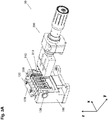
- FIG. 1A depicts a perspective side view of an embodiment of the sonication device (10) disclosed herein.
- the sample tube or tubes (300) and the sample tube holder (100) are omitted for the sake of better visibility of the other components.
- the corresponding mount (110) for the sample tube holder comprises an immobile base portion (160) and a rotatable portion (170) comprising a base (171) for holding, in this case, a sample tube holder (100) with five individual sample tubes (300).
- the rotatable portion (170) also comprises at both sides a pivot (130) whose pivot point defines the x-axis (150) about which the rotatable portion (170) and thus the sample tube holder (100), when inserted, is rotatable.
- the pivot (130) here depicted as a hinge, is held by a corresponding pivot bearing (161) of the immobile base portion (160) of the mount.
- the rotatable portion (170) of this embodiment further has a height adjustment (120), in the depicted case a manually operable mechanism based on screws (120) for lifting or lowering the base (171) holding the sample tube holder (100).
- the entire sample holder (100) can thus be vertically adjusted, such that the sample tubes (300) and the biological samples contained therein can be adjusted to the height of the sonicating area (210) of the sonotrode (200).
- the sonication area (210) of this embodiment comprises five sub-areas (211) for the maximum load of five individual sample tubes (300).
- This sonicating area (210) of the sonotrode (200) faces towards an opening (140) to one side of the sample tube holder (100, not shown) such that it can be brought into physical contact with the sample tube or tubes (300) through the opening (140).
- the guiding rail (220) of the sonotrode (200) of the present embodiment comprises a sled (221) on which the sonotrode (200) is mounted, with the sled (221) itself being mounted via a connector (222) to a railing (223).
- This guiding rail (220) arrangement provides movability of the sonotrode (200) along the y-axis (250). It can be seen that this movability is one-dimensional, such that the sonotrode (200) can be moved with the help of an actuator (400) towards or away from the mount (110) for the sample tube holder (100), while the guiding rail (220) is fixed at one end to said mount (110), in this embodiment to its immobile base portion (160).
- the mount (110) is essentially in alignment with the z-axis (350), essentially parallel to the direction of gravity. Also visible in this depiction is the composition of the sonotrode (200) of the embodiment shown here.
- the piezoelectric elements are contained within the converter (201) transforming a primary electrical signal into mechanical vibration. The latter is amplified by the subsequent booster (202), before the following transmittal unit (203) transmits the energy via its sonicating area (210).
- Fig. 1B shows the sonication device (10) of Fig. 1A in a sonication position.
- the sonotrode has been moved towards the sample tube holder (100) mounted to the rotatable part (170) of the corresponding mount (110).
- the sonicating area (210) with its individual sub-areas (211) are in contact with the sample tubes (300) held within the sample tube holder (100) through the corresponding openings (140).
- FIG. 2A the sonication device (10) of Fig. 1 is now depicted as a cross-sectional side view.
- the sonicating area (210) is mounted at essentially the same height as the pivot (130). Also visible is the vertical dimension of the sonicating area (210), along with its vertical center (215) that is mounted at the same height as the pivot point defined by the x-axis (150).
- a depiction of the sonication device (10) from the cross-sectional side-perspective of Fig. 2A is shown in a sonication position in Fig. 2B .
- FIG. 3 and Fig. 4 provide an illustration of an embodiment of the method described herein using the sonication device (10) described herein as depicted in the foregoing Figures.
- Fig. 3A shows a perspective side view of the above-depicted embodiment of the sonication device (10) described herein.
- the guiding rail (220) has been omitted for the sake of better visibility of the mount (110) with the inserted sample tube holder (100).
- the sonotrode (200) is located in a remote position, in which there is no direct physical contact between the sonicating area (210) and the side wall (310) of the sample tube (300).
- the rotatable portion (170) of the mount (110) is slightly tilted against the z-axis (350), which can be seen in more detail in the corresponding cross-sectional side view of Fig. 4A .
- the configuration of the sonication device (10) of this embodiment in a sonication position is shown in Fig. 3B and Fig. 4B .
- the portion of the side wall (310) located above the vertical center (215) of the sonicating area (210) and thus the x-axis (150) being the pivot point of the pivot (130) is rotated counter-clockwise about the x-axis (150).
- the rotatable part (170) follows this rotational movement of the sample tubes (300) until reaching the arresting point seen in present Figs. 3B and 4B .
- the sample tubes (300) are vertical and thus parallel to the z-axis (350). This is due to the circumstance that the side walls (310) sample tubes (300) shown in Figs.
- the sonicating area (210) of the sonotrode (200), including the sonicating sub-areas (211) are aligned parallel to the z-axis (350).
- the vertical position of the sample tube (300) in the sample tube holder (100) and the rotatable part (170) of the mount (110) represents the position in which the sample tube side wall (310) and the sonicating area (210) possess the optimal contact area, thus facilitating efficient transfer of ultrasonic (kinetic) energy from the sonotrode (200) to the biological sample.
Landscapes
- Chemical & Material Sciences (AREA)
- Health & Medical Sciences (AREA)
- Life Sciences & Earth Sciences (AREA)
- Engineering & Computer Science (AREA)
- Organic Chemistry (AREA)
- Genetics & Genomics (AREA)
- General Health & Medical Sciences (AREA)
- Wood Science & Technology (AREA)
- Zoology (AREA)
- Bioinformatics & Cheminformatics (AREA)
- Biochemistry (AREA)
- Biotechnology (AREA)
- General Engineering & Computer Science (AREA)
- Biomedical Technology (AREA)
- Chemical Kinetics & Catalysis (AREA)
- Microbiology (AREA)
- Physics & Mathematics (AREA)
- General Physics & Mathematics (AREA)
- Analytical Chemistry (AREA)
- Pathology (AREA)
- Immunology (AREA)
- Toxicology (AREA)
- Molecular Biology (AREA)
- Biophysics (AREA)
- Plant Pathology (AREA)
- Mechanical Engineering (AREA)
- Cell Biology (AREA)
- Sustainable Development (AREA)
- Apparatus Associated With Microorganisms And Enzymes (AREA)
- Sampling And Sample Adjustment (AREA)
- Measuring Or Testing Involving Enzymes Or Micro-Organisms (AREA)
Priority Applications (6)
| Application Number | Priority Date | Filing Date | Title |
|---|---|---|---|
| EP18165846.9A EP3549664A1 (fr) | 2018-04-05 | 2018-04-05 | Procédé et dispositif pour la sonication d'un échantillon biologique |
| JP2019071015A JP7197424B2 (ja) | 2018-04-05 | 2019-04-03 | 生体試料を超音波処理する方法および装置 |
| CN201910272650.4A CN110511921A (zh) | 2018-04-05 | 2019-04-04 | 用于对生物样品进行超声处理的方法和装置 |
| EP19167291.4A EP3549665B1 (fr) | 2018-04-05 | 2019-04-04 | Procédé et dispositif pour la sonication d'un échantillon biologique |
| US16/376,286 US11666873B2 (en) | 2018-04-05 | 2019-04-05 | Method and device for sonicating a biological sample |
| US18/137,677 US20230249144A1 (en) | 2018-04-05 | 2023-04-21 | Method and device for sonicating a biological sample |
Applications Claiming Priority (1)
| Application Number | Priority Date | Filing Date | Title |
|---|---|---|---|
| EP18165846.9A EP3549664A1 (fr) | 2018-04-05 | 2018-04-05 | Procédé et dispositif pour la sonication d'un échantillon biologique |
Publications (1)
| Publication Number | Publication Date |
|---|---|
| EP3549664A1 true EP3549664A1 (fr) | 2019-10-09 |
Family
ID=61911417
Family Applications (2)
| Application Number | Title | Priority Date | Filing Date |
|---|---|---|---|
| EP18165846.9A Pending EP3549664A1 (fr) | 2018-04-05 | 2018-04-05 | Procédé et dispositif pour la sonication d'un échantillon biologique |
| EP19167291.4A Active EP3549665B1 (fr) | 2018-04-05 | 2019-04-04 | Procédé et dispositif pour la sonication d'un échantillon biologique |
Family Applications After (1)
| Application Number | Title | Priority Date | Filing Date |
|---|---|---|---|
| EP19167291.4A Active EP3549665B1 (fr) | 2018-04-05 | 2019-04-04 | Procédé et dispositif pour la sonication d'un échantillon biologique |
Country Status (4)
| Country | Link |
|---|---|
| US (2) | US11666873B2 (fr) |
| EP (2) | EP3549664A1 (fr) |
| JP (1) | JP7197424B2 (fr) |
| CN (1) | CN110511921A (fr) |
Cited By (1)
| Publication number | Priority date | Publication date | Assignee | Title |
|---|---|---|---|---|
| CN111729592A (zh) * | 2020-08-21 | 2020-10-02 | 宁波海壹生物科技有限公司 | 一种反应管抓取混匀装置以及抓取混匀方法 |
Families Citing this family (1)
| Publication number | Priority date | Publication date | Assignee | Title |
|---|---|---|---|---|
| CN112779157B (zh) * | 2021-01-08 | 2022-06-21 | 鲲鹏基因(北京)科技有限责任公司 | 具备样品制备功能的pcr反应装置 |
Citations (4)
| Publication number | Priority date | Publication date | Assignee | Title |
|---|---|---|---|---|
| FR2791697A1 (fr) * | 1999-04-01 | 2000-10-06 | Biomerieux Sa | Appareil et procede de lyse par ultrasons de cellules biologiques |
| US20030209427A1 (en) * | 1999-10-01 | 2003-11-13 | Nanoplex, Technologies | Method and apparatus for manufacturing colloidal rod particles |
| US20040178076A1 (en) * | 1999-10-01 | 2004-09-16 | Stonas Walter J. | Method of manufacture of colloidal rod particles as nanobarcodes |
| US20140272938A1 (en) * | 2013-03-15 | 2014-09-18 | Theranos, Inc. | Devices, systems and methods for sample preparation |
Family Cites Families (17)
| Publication number | Priority date | Publication date | Assignee | Title |
|---|---|---|---|---|
| US4431423A (en) * | 1982-03-10 | 1984-02-14 | E. I. Du Pont De Nemours & Co. | Cell washing apparatus having radially inwardly directed retaining arms |
| US5178602A (en) * | 1990-02-07 | 1993-01-12 | Wells John R | Automatic decanting centrifuge |
| US6318158B1 (en) * | 2000-03-01 | 2001-11-20 | Coulter International Corp. | Sample preparation and delivery system employing external sonicator |
| GB0303913D0 (en) * | 2003-02-21 | 2003-03-26 | Sophion Bioscience As | Robot centrifugation device |
| US7285895B2 (en) * | 2005-03-15 | 2007-10-23 | Crescendo Technologies, Llc | Ultrasonic medical device and method |
| JP4855182B2 (ja) * | 2005-08-29 | 2012-01-18 | 株式会社ユネクス | 血管画像測定装置 |
| US7862512B2 (en) * | 2005-08-29 | 2011-01-04 | Unex Corporation | Blood vessel endothelium function evaluating apparatus provided with an electronic control device |
| WO2012125708A2 (fr) * | 2011-03-15 | 2012-09-20 | E. I. Du Pont De Nemours And Company | Dispositif de coupe d'acides nucléiques et de particules |
| DE102011083794A1 (de) * | 2011-09-29 | 2013-04-04 | Hamilton Bonaduz Ag | Greifvorrichtung für Probenbehälter |
| CN102728428B (zh) * | 2012-07-21 | 2014-07-02 | 深圳市华测检测技术股份有限公司 | 试管废液自动收集设备 |
| MX368673B (es) * | 2013-03-15 | 2019-10-10 | Theranos Ip Co Llc | Dispositivos, sistemas y métodos para preparar muestras. |
| JP6392791B2 (ja) * | 2013-03-15 | 2018-09-19 | メルク パテント ゲゼルシャフト ミット ベシュレンクテル ハフツングMerck Patent Gesellschaft mit beschraenkter Haftung | 超音波処理を行うための装置 |
| US11092521B2 (en) * | 2013-08-21 | 2021-08-17 | Covaris, Inc. | Method and system for acoustically treating material |
| FR3025729B1 (fr) * | 2014-09-17 | 2016-12-09 | Bertin Technologies Sa | Ensemble pour le broyage d'echantillons biologiques |
| FR3036799A1 (fr) * | 2015-05-28 | 2016-12-02 | Biomerieux Sa | Dispositif pour la preparation d'echantillons biologiques |
| CN105413786B (zh) * | 2015-12-21 | 2017-12-22 | 安徽农业大学 | 一种倾斜角度可调的恒温试管架 |
| CN216799902U (zh) * | 2021-12-30 | 2022-06-24 | 广州汇标检测技术中心 | 一种侧夹式实验容器超声固定装置 |
-
2018
- 2018-04-05 EP EP18165846.9A patent/EP3549664A1/fr active Pending
-
2019
- 2019-04-03 JP JP2019071015A patent/JP7197424B2/ja active Active
- 2019-04-04 CN CN201910272650.4A patent/CN110511921A/zh active Pending
- 2019-04-04 EP EP19167291.4A patent/EP3549665B1/fr active Active
- 2019-04-05 US US16/376,286 patent/US11666873B2/en active Active
-
2023
- 2023-04-21 US US18/137,677 patent/US20230249144A1/en active Pending
Patent Citations (5)
| Publication number | Priority date | Publication date | Assignee | Title |
|---|---|---|---|---|
| FR2791697A1 (fr) * | 1999-04-01 | 2000-10-06 | Biomerieux Sa | Appareil et procede de lyse par ultrasons de cellules biologiques |
| US6686195B1 (en) | 1999-04-01 | 2004-02-03 | Biomerieux S.A. | Method and apparatus for ultrasonic lysis of biological cells |
| US20030209427A1 (en) * | 1999-10-01 | 2003-11-13 | Nanoplex, Technologies | Method and apparatus for manufacturing colloidal rod particles |
| US20040178076A1 (en) * | 1999-10-01 | 2004-09-16 | Stonas Walter J. | Method of manufacture of colloidal rod particles as nanobarcodes |
| US20140272938A1 (en) * | 2013-03-15 | 2014-09-18 | Theranos, Inc. | Devices, systems and methods for sample preparation |
Cited By (2)
| Publication number | Priority date | Publication date | Assignee | Title |
|---|---|---|---|---|
| CN111729592A (zh) * | 2020-08-21 | 2020-10-02 | 宁波海壹生物科技有限公司 | 一种反应管抓取混匀装置以及抓取混匀方法 |
| CN111729592B (zh) * | 2020-08-21 | 2020-11-13 | 宁波海壹生物科技有限公司 | 一种反应管抓取混匀装置以及抓取混匀方法 |
Also Published As
| Publication number | Publication date |
|---|---|
| US11666873B2 (en) | 2023-06-06 |
| JP7197424B2 (ja) | 2022-12-27 |
| CN110511921A (zh) | 2019-11-29 |
| US20230249144A1 (en) | 2023-08-10 |
| US20190308147A1 (en) | 2019-10-10 |
| EP3549665A1 (fr) | 2019-10-09 |
| JP2019184602A (ja) | 2019-10-24 |
| EP3549665B1 (fr) | 2020-08-26 |
Similar Documents
| Publication | Publication Date | Title |
|---|---|---|
| US20230249144A1 (en) | Method and device for sonicating a biological sample | |
| JP5776772B2 (ja) | ロボットハンド及びロボット | |
| US20150104798A1 (en) | Microdroplet-manipulation systems and methods for automated execution of molecular biological protocols | |
| EP2884285A1 (fr) | Module d'alimentation pour analyseur automatisé | |
| CN105102110B (zh) | 用于执行声处理的设备 | |
| US20190239975A1 (en) | System for the thermally controlled processing of a biological sample | |
| US20150050185A1 (en) | Sample Distribution | |
| KR20170134383A (ko) | 시료 채취 장치 및 시료 채취 장치와 시료 용기의 조합 | |
| US11970692B2 (en) | Magnet assembly to prevent extraction particle carryover | |
| US20200150009A1 (en) | Particle Mixing | |
| EP2677321A1 (fr) | Dispositif intégré pour l'hybridation d'acides nucléiques et analyses immunologiques | |
| EP4184173A1 (fr) | Système analytique automatisé pour le traitement d'échantillons biologiques | |
| EP4279228A1 (fr) | Appareil de préhension permettant de saisir un récipient d'échantillons | |
| EP4312028A1 (fr) | Procédé de fermeture de récipient d'échantillon, dispositif de préhension de capuchon mobile et système de fermeture de récipient d'échantillon pour fermer automatiquement une extrémité ouverte d'un récipient d'échantillon avec un capuchon de fermeture | |
| EP4253523A1 (fr) | Compartiment agitateur d'incubateur automatisé | |
| JP2000088715A (ja) | グリッディングピン |
Legal Events
| Date | Code | Title | Description |
|---|---|---|---|
| PUAI | Public reference made under article 153(3) epc to a published international application that has entered the european phase |
Free format text: ORIGINAL CODE: 0009012 |
|
| STAA | Information on the status of an ep patent application or granted ep patent |
Free format text: STATUS: THE APPLICATION HAS BEEN PUBLISHED |
|
| AK | Designated contracting states |
Kind code of ref document: A1 Designated state(s): AL AT BE BG CH CY CZ DE DK EE ES FI FR GB GR HR HU IE IS IT LI LT LU LV MC MK MT NL NO PL PT RO RS SE SI SK SM TR |
|
| AX | Request for extension of the european patent |
Extension state: BA ME |
|
| STAA | Information on the status of an ep patent application or granted ep patent |
Free format text: STATUS: REQUEST FOR EXAMINATION WAS MADE |
|
| 17P | Request for examination filed |
Effective date: 20200409 |
|
| RBV | Designated contracting states (corrected) |
Designated state(s): AL AT BE BG CH CY CZ DE DK EE ES FI FR GB GR HR HU IE IS IT LI LT LU LV MC MK MT NL NO PL PT RO RS SE SI SK SM TR |