EP3549292B1 - Code polaire concaténé avec détection d'erreur adaptative - Google Patents
Code polaire concaténé avec détection d'erreur adaptative Download PDFInfo
- Publication number
- EP3549292B1 EP3549292B1 EP18708205.2A EP18708205A EP3549292B1 EP 3549292 B1 EP3549292 B1 EP 3549292B1 EP 18708205 A EP18708205 A EP 18708205A EP 3549292 B1 EP3549292 B1 EP 3549292B1
- Authority
- EP
- European Patent Office
- Prior art keywords
- bits
- precoder bits
- error detection
- precoder
- error correction
- Prior art date
- Legal status (The legal status is an assumption and is not a legal conclusion. Google has not performed a legal analysis and makes no representation as to the accuracy of the status listed.)
- Active
Links
- 238000001514 detection method Methods 0.000 title claims description 114
- 230000003044 adaptive effect Effects 0.000 title description 7
- 238000012937 correction Methods 0.000 claims description 93
- 238000000034 method Methods 0.000 claims description 47
- 125000004122 cyclic group Chemical group 0.000 claims description 3
- 230000006870 function Effects 0.000 description 30
- 241000169170 Boreogadus saida Species 0.000 description 20
- 238000012545 processing Methods 0.000 description 14
- 230000010267 cellular communication Effects 0.000 description 12
- 238000004891 communication Methods 0.000 description 11
- 238000001228 spectrum Methods 0.000 description 9
- 238000013461 design Methods 0.000 description 8
- 230000008569 process Effects 0.000 description 8
- 230000008901 benefit Effects 0.000 description 7
- 230000006978 adaptation Effects 0.000 description 6
- 238000010586 diagram Methods 0.000 description 6
- 238000005516 engineering process Methods 0.000 description 5
- 230000002860 competitive effect Effects 0.000 description 4
- 238000004590 computer program Methods 0.000 description 4
- 230000003287 optical effect Effects 0.000 description 4
- 238000007476 Maximum Likelihood Methods 0.000 description 2
- 238000013459 approach Methods 0.000 description 2
- 230000004075 alteration Effects 0.000 description 1
- 238000003491 array Methods 0.000 description 1
- 230000005540 biological transmission Effects 0.000 description 1
- 239000000969 carrier Substances 0.000 description 1
- 238000010276 construction Methods 0.000 description 1
- 238000011156 evaluation Methods 0.000 description 1
- 230000007774 longterm Effects 0.000 description 1
- 238000012986 modification Methods 0.000 description 1
- 230000004048 modification Effects 0.000 description 1
- 230000006855 networking Effects 0.000 description 1
- 230000010287 polarization Effects 0.000 description 1
- 230000011664 signaling Effects 0.000 description 1
Images


Classifications
-
- H—ELECTRICITY
- H03—ELECTRONIC CIRCUITRY
- H03M—CODING; DECODING; CODE CONVERSION IN GENERAL
- H03M13/00—Coding, decoding or code conversion, for error detection or error correction; Coding theory basic assumptions; Coding bounds; Error probability evaluation methods; Channel models; Simulation or testing of codes
- H03M13/35—Unequal or adaptive error protection, e.g. by providing a different level of protection according to significance of source information or by adapting the coding according to the change of transmission channel characteristics
- H03M13/353—Adaptation to the channel
-
- H—ELECTRICITY
- H03—ELECTRONIC CIRCUITRY
- H03M—CODING; DECODING; CODE CONVERSION IN GENERAL
- H03M13/00—Coding, decoding or code conversion, for error detection or error correction; Coding theory basic assumptions; Coding bounds; Error probability evaluation methods; Channel models; Simulation or testing of codes
- H03M13/03—Error detection or forward error correction by redundancy in data representation, i.e. code words containing more digits than the source words
- H03M13/05—Error detection or forward error correction by redundancy in data representation, i.e. code words containing more digits than the source words using block codes, i.e. a predetermined number of check bits joined to a predetermined number of information bits
- H03M13/09—Error detection only, e.g. using cyclic redundancy check [CRC] codes or single parity bit
- H03M13/095—Error detection codes other than CRC and single parity bit codes
- H03M13/096—Checksums
-
- H—ELECTRICITY
- H03—ELECTRONIC CIRCUITRY
- H03M—CODING; DECODING; CODE CONVERSION IN GENERAL
- H03M13/00—Coding, decoding or code conversion, for error detection or error correction; Coding theory basic assumptions; Coding bounds; Error probability evaluation methods; Channel models; Simulation or testing of codes
- H03M13/03—Error detection or forward error correction by redundancy in data representation, i.e. code words containing more digits than the source words
- H03M13/05—Error detection or forward error correction by redundancy in data representation, i.e. code words containing more digits than the source words using block codes, i.e. a predetermined number of check bits joined to a predetermined number of information bits
- H03M13/09—Error detection only, e.g. using cyclic redundancy check [CRC] codes or single parity bit
- H03M13/098—Error detection only, e.g. using cyclic redundancy check [CRC] codes or single parity bit using single parity bit
-
- H—ELECTRICITY
- H03—ELECTRONIC CIRCUITRY
- H03M—CODING; DECODING; CODE CONVERSION IN GENERAL
- H03M13/00—Coding, decoding or code conversion, for error detection or error correction; Coding theory basic assumptions; Coding bounds; Error probability evaluation methods; Channel models; Simulation or testing of codes
- H03M13/03—Error detection or forward error correction by redundancy in data representation, i.e. code words containing more digits than the source words
- H03M13/05—Error detection or forward error correction by redundancy in data representation, i.e. code words containing more digits than the source words using block codes, i.e. a predetermined number of check bits joined to a predetermined number of information bits
- H03M13/11—Error detection or forward error correction by redundancy in data representation, i.e. code words containing more digits than the source words using block codes, i.e. a predetermined number of check bits joined to a predetermined number of information bits using multiple parity bits
- H03M13/1102—Codes on graphs and decoding on graphs, e.g. low-density parity check [LDPC] codes
- H03M13/1148—Structural properties of the code parity-check or generator matrix
-
- H—ELECTRICITY
- H03—ELECTRONIC CIRCUITRY
- H03M—CODING; DECODING; CODE CONVERSION IN GENERAL
- H03M13/00—Coding, decoding or code conversion, for error detection or error correction; Coding theory basic assumptions; Coding bounds; Error probability evaluation methods; Channel models; Simulation or testing of codes
- H03M13/03—Error detection or forward error correction by redundancy in data representation, i.e. code words containing more digits than the source words
- H03M13/05—Error detection or forward error correction by redundancy in data representation, i.e. code words containing more digits than the source words using block codes, i.e. a predetermined number of check bits joined to a predetermined number of information bits
- H03M13/13—Linear codes
-
- H—ELECTRICITY
- H03—ELECTRONIC CIRCUITRY
- H03M—CODING; DECODING; CODE CONVERSION IN GENERAL
- H03M13/00—Coding, decoding or code conversion, for error detection or error correction; Coding theory basic assumptions; Coding bounds; Error probability evaluation methods; Channel models; Simulation or testing of codes
- H03M13/27—Coding, decoding or code conversion, for error detection or error correction; Coding theory basic assumptions; Coding bounds; Error probability evaluation methods; Channel models; Simulation or testing of codes using interleaving techniques
- H03M13/2792—Interleaver wherein interleaving is performed jointly with another technique such as puncturing, multiplexing or routing
-
- H—ELECTRICITY
- H03—ELECTRONIC CIRCUITRY
- H03M—CODING; DECODING; CODE CONVERSION IN GENERAL
- H03M13/00—Coding, decoding or code conversion, for error detection or error correction; Coding theory basic assumptions; Coding bounds; Error probability evaluation methods; Channel models; Simulation or testing of codes
- H03M13/29—Coding, decoding or code conversion, for error detection or error correction; Coding theory basic assumptions; Coding bounds; Error probability evaluation methods; Channel models; Simulation or testing of codes combining two or more codes or code structures, e.g. product codes, generalised product codes, concatenated codes, inner and outer codes
- H03M13/2906—Coding, decoding or code conversion, for error detection or error correction; Coding theory basic assumptions; Coding bounds; Error probability evaluation methods; Channel models; Simulation or testing of codes combining two or more codes or code structures, e.g. product codes, generalised product codes, concatenated codes, inner and outer codes using block codes
-
- H—ELECTRICITY
- H04—ELECTRIC COMMUNICATION TECHNIQUE
- H04L—TRANSMISSION OF DIGITAL INFORMATION, e.g. TELEGRAPHIC COMMUNICATION
- H04L1/00—Arrangements for detecting or preventing errors in the information received
- H04L1/004—Arrangements for detecting or preventing errors in the information received by using forward error control
- H04L1/0056—Systems characterized by the type of code used
- H04L1/0057—Block codes
-
- H—ELECTRICITY
- H04—ELECTRIC COMMUNICATION TECHNIQUE
- H04L—TRANSMISSION OF DIGITAL INFORMATION, e.g. TELEGRAPHIC COMMUNICATION
- H04L1/00—Arrangements for detecting or preventing errors in the information received
- H04L1/004—Arrangements for detecting or preventing errors in the information received by using forward error control
- H04L1/0056—Systems characterized by the type of code used
- H04L1/0061—Error detection codes
-
- H—ELECTRICITY
- H04—ELECTRIC COMMUNICATION TECHNIQUE
- H04L—TRANSMISSION OF DIGITAL INFORMATION, e.g. TELEGRAPHIC COMMUNICATION
- H04L1/00—Arrangements for detecting or preventing errors in the information received
- H04L1/004—Arrangements for detecting or preventing errors in the information received by using forward error control
- H04L1/0056—Systems characterized by the type of code used
- H04L1/0064—Concatenated codes
-
- H—ELECTRICITY
- H04—ELECTRIC COMMUNICATION TECHNIQUE
- H04L—TRANSMISSION OF DIGITAL INFORMATION, e.g. TELEGRAPHIC COMMUNICATION
- H04L1/00—Arrangements for detecting or preventing errors in the information received
- H04L1/004—Arrangements for detecting or preventing errors in the information received by using forward error control
- H04L1/0072—Error control for data other than payload data, e.g. control data
-
- H—ELECTRICITY
- H04—ELECTRIC COMMUNICATION TECHNIQUE
- H04L—TRANSMISSION OF DIGITAL INFORMATION, e.g. TELEGRAPHIC COMMUNICATION
- H04L1/00—Arrangements for detecting or preventing errors in the information received
- H04L1/004—Arrangements for detecting or preventing errors in the information received by using forward error control
- H04L1/0056—Systems characterized by the type of code used
- H04L1/0071—Use of interleaving
Definitions
- Embodiments of the invention relate to the field of wireless communication; and more specifically, to methods, apparatus and systems for implementing concatenated Polar code with adoptive error detection.
- Polar codes proposed by E. Arikan in “Channel Polarization: A Method for Constructing Capacity-Achieving Codes for Symmetric Binary-Input Memoryless Channels," IEEE Transactions on Information Theory, vol. 55, pp. 3051-3073, Jul. 2009 , are the first class of constructive coding schemes that are provable to achieve the symmetric capacity of the binary-input discrete memoryless channels under a low-complexity successive cancellation (SC) decoder.
- SC successive cancellation
- the finite-length performance of Polar codes under SC is not competitive compared to other modern channel coding schemes such as low-density parity-check (LDPC) codes and Turbo codes.
- LDPC low-density parity-check
- SCL SC list
- Polar coding is to transform a pair of identical binary-input channels into two distinct channels of different qualities, one better and one worse than the original binary-input channel.
- a pair-wise Polarizing operation on a set of 2 M independent uses of a binary-input channel, a set of 2 M "bit-channels" of varying qualities can be obtained.
- Some of these bit channels are nearly perfect (i.e. error free) while the rest of them are nearly useless (i.e. totally noisy).
- the point is to use the nearly perfect channel to transmit data to the receiver while setting the input to the useless channels to have fixed or frozen values (e.g. 0) known to the receiver.
- Vardy further proposed that by concatenating a linear outer code, namely a CRC code, with the original Polar code as inner code, the outer code can be used to check if any of the candidate paths in the list is correctly decoded.
- a linear outer code namely a CRC code
- the outer code can be used to check if any of the candidate paths in the list is correctly decoded.
- PC-Polar Another type of concatenated Polar codes is PC-Polar, where a sequence of parity checksum (PC) bits are generated before Polar encoding. Similar to CA-Polar, the sequence of PC bits are fixed for a given (K, M), and all the PC bits are used for error correction. Here K is the number of information bits, and M the number of coded bits to send over the air. For PC-Polar, it is also desirable to have adaptive error detection and error correction capability.
- PC parity checksum
- 3GPP R1-1700088 "Summary of polar code design for control channels", Huawei, HiSilicon , discloses a design of parity-check (PC) polar codes.
- aspects of embodiments provide systems and methods for adaptively selecting a total number of CRC or PC bits and/or allocating a different amount of the available CRC bits between error detection and error correction for Polar codes.
- an advantage of features herein is to allow the concatenation of CRC code to be customized for different amounts of payloads, different coding parameters needed for the varying communication channel conditions, and different types of applications with different requirements in terms of, for example, latency and reliability. Since 5G wireless communications need to cover a wide range of circumstances and applications, embodiments of this disclosure allow the system to judiciously allocate radio resources based on cost-benefit tradeoffs.
- references in the specification to "one embodiment,” “an embodiment,” “an example embodiment,” etc., indicate that the embodiment described may include a particular feature, structure, or characteristic, but every embodiment may not necessarily include the particular feature, structure, or characteristic. Moreover, such phrases are not necessarily referring to the same embodiment. Further, when a particular feature, structure, or characteristic is described in connection with an embodiment, it is submitted that it is within the knowledge of one skilled in the art to implement such feature, structure, or characteristic in connection with other embodiments whether or not explicitly described.
- Coupled is used to indicate that two or more elements, which may or may not be in direct physical or electrical contact with each other, co-operate or interact with each other.
- Connected is used to indicate the establishment of communication between two or more elements that are coupled with each other.
- Radio Node As used herein, a "radio node” is either a radio access node or a wireless device.
- Radio Access Node is any node in a radio access network of a cellular communications network that operates to wirelessly transmit and/or receive signals.
- a radio access node include, but are not limited to, a base station (e.g., an enhanced or evolved Node B (eNB) in a Third Generation Partnership Project (3GPP) Long Term Evolution (LTE) network), a high-power or macro base station, a low-power base station (e.g., a micro base station, a pico base station, a home eNB, or the like), and a relay node.
- a base station e.g., an enhanced or evolved Node B (eNB) in a Third Generation Partnership Project (3GPP) Long Term Evolution (LTE) network
- 3GPP Third Generation Partnership Project
- LTE Long Term Evolution
- a “core network node” is any type of node in a core network.
- Some examples of a core network node include, e.g., a Mobility Management Entity (MME), a Packet Data Network (PDN) Gateway (P-GW), a Service Capability Exposure Function (SCEF), or the like.
- MME Mobility Management Entity
- PDN Packet Data Network
- SCEF Service Capability Exposure Function
- a “wireless device” is any type of device that has access to (i.e., is served by) a cellular communications network by wirelessly transmitting and/or receiving signals to a radio access node(s).
- a wireless device include, but are not limited to, a User Equipment device (UE) in a 3GPP network and a Machine Type Communication (MTC) device.
- UE User Equipment device
- MTC Machine Type Communication
- Network Node As used herein, a "network node” is any node that is either part of the radio access network or the core network of a cellular communications network/system.
- 3GPP LTE terminology or terminology similar to 3GPP LTE terminology is oftentimes used.
- the concepts disclosed herein are not limited to LTE or a 3GPP system.
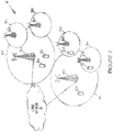
- FIGURE 2 illustrates one example of a cellular communications network 10 according to some embodiments of the present disclosure.
- the cellular communications network 10 is an LTE network in which some or all of the radio access nodes operate on a carrier(s) in an unlicensed spectrum.
- cellular communications network 10 may operate on the 5 gigahertz (GHz) spectrum.
- GHz gigahertz
- the present disclosure is not limited thereto. Accordingly, in another example, the cellular communications network 10 may implement LAA, LTE-U, MulteFire, or some other technology in which radio access nodes operate on an unlicensed carriers(s).
- the cellular communications network 10 includes base stations 12-1 and 12-2, which in LTE are referred to as eNBs, controlling corresponding macro cells 14-1 and 14-2.
- the base stations 12-1 and 12-2 are generally referred to herein collectively as base stations 12 and individually as base station 12.
- the macro cells 14-1 and 14-2 are generally referred to herein collectively as macro cells 14 and individually as macro cell 14.
- the cellular communications network 10 also includes a number of low power nodes 16-1 through 16-4 controlling corresponding small cells 18-1 through 18-4.
- the low power nodes 16-1 through 16-4 can be small base stations (such as pico or femto base stations) or Remote Radio Heads (RRHs), or the like.
- RRHs Remote Radio Heads
- the small cells 18-1 through 18-4 may alternatively be provided by the base stations 12.
- the low power nodes 16-1 through 16-4 are generally referred to herein collectively as low power nodes 16 and individually as low power node 16.
- the small cells 18-1 through 18-4 are generally referred to herein collectively as small cells 18 and individually as small cell 18.
- the base stations 12 (and optionally the low power nodes 16) are connected to a core network 20.
- the base stations 12 and the low power nodes 16 provide service to wireless devices 22-1 through 22-5 in the corresponding cells 14 and 18.
- the wireless devices 22-1 through 22-5 are generally referred to herein collectively as wireless devices 22 and individually as wireless device 22.
- the wireless devices 22 are referred to as UEs.
- the macro cells 14 may be provided in a licensed frequency spectrum (i.e., in the frequency spectrum dedicated for the cellular communications network 10) such as, for example, for LAA operation.
- the macro cells 14 may be provided in an unlicensed frequency spectrum such as, for example, for LAA in the unlicensed spectrum (LAA-U) or MulteFire operation.
- one or more (and possibly all) of the small cells 18 may be provided in an unlicensed frequency spectrum such as, for example, the 5 GHz frequency spectrum.
- base stations 12, 14 that operate on a carrier(s) in an unlicensed spectrum may operate to perform LBT and transmitMultimedia. Broadcast Multicast. Services (MBMS) data according to any of the embodiments described herein.
- MBMS Broadcast Multicast. Services
- FIGURE 3 is a schematic block diagram of radio access node 24, according to certain embodiments.
- the radio access node 24 may be, for example, a base station 12, 16.
- the radio access node 24 includes a control system 26 that includes one or more processors 28 (e.g., Central Processing Units (CPUs), Application Specific Integrated Circuits (ASICs), Field Programmable Gate Arrays (FPGAs), and/or the like), memory 30, and a network interface 32.
- processors 28 e.g., Central Processing Units (CPUs), Application Specific Integrated Circuits (ASICs), Field Programmable Gate Arrays (FPGAs), and/or the like
- the radio access node 24 includes one or more radio units 34 that each includes one or more transmitters 36 and one or more receivers 38 coupled to one or more antennas 40.
- the radio unit(s) 34 is external to the control system 26 and connected to the control system 26 via, for example, a wired connection such as, for example, an optical cable.
- the radio unit(s) 34 and potentially the antenna(s) 40 may be integrated together with the control system 26.
- the one or more processors 28 may operate to provide one or more functions of a radio access node 24 as described herein.
- the function(s) may be implemented in software that is stored such as, for example, in the memory 30 and executed by the one or more processors 28.
- FIGURE 4 is a schematic block diagram that illustrates a virtualized embodiment of the radio access node 24, according to certain embodiments. However, the description thereof may be equally applicable to other types of network nodes. Further, any of the types of network nodes may have similar virtualized architectures.
- a "virtualized" radio access node is an implementation of the radio access node 24 in which at least a portion of the functionality of the radio access node 24 is implemented as a virtual component(s).
- the functionality of the radio access node may be implemented via a virtual machine(s) executing on a physical processing node(s) in a network(s), in a particular embodiment.
- the radio access node 24 includes the control system 26 that includes the one or more processors 28 (e.g., CPUs, ASICs, FPGAs, and/or the like), the memory 30, and the network interface 32 and the one or more radio units 34 that each includes the one or more transmitters 36 and the one or more receivers 38 coupled to the one or more antennas 40, as described above.
- the control system 26 is connected to the radio unit(s) 34 via, for example, an optical cable or the like.
- the control system 26 is connected to one or more processing nodes 42 coupled to or included as part of a network(s) 44 via the network interface 32.
- Each processing node 42 includes one or more processors 46 (e.g., CPUs, ASICs, FPGAs, and/or the like), memory 48, and a network interface 50.
- functions 52 of the radio access node 24 described herein may be implemented at the one or more processing nodes 42 or distributed across the control system 26 and the one or more processing nodes 42 in any desired manner.
- some or all of the functions 52 of the radio access node 24 described herein are implemented as virtual components executed by one or more virtual machines implemented in a virtual environment(s) hosted by the processing node(s) 42.
- additional signaling or communication between the processing node(s) 42 and the control system 26 may be used in order to carry out at least some of the desired functions 52.
- the control system 26 may not be included, in which case the radio unit(s) 34 communicate directly with the processing node(s) 42 via an appropriate network interface(s).
- a computer program including instructions which, when executed by at least one processor, causes the at least one processor to carry out the functionality of radio access node 24 or a node (e.g., a processing node 42) implementing one or more of the functions 52 of the radio access node 24 in a virtual environment according to any of the embodiments described herein is provided.
- a carrier comprising the aforementioned computer program product is provided.
- the carrier is one of an electronic signal, an optical signal, a radio signal, or a computer readable storage medium (e.g., a non-transitory computer readable medium such as memory).
- FIGURE 5 is a schematic block diagram illustrating another example radio access node 24, according to certain other embodiments.
- the radio access node 24 includes one or more modules 54, each of which is implemented in software.
- the module(s) 54 provide the functionality of the radio access node 24 described herein. This discussion is equally applicable to the processing node 42 of FIGURE 7 (described below) where the modules 54 may be implemented at one of the processing nodes 42 or distributed across multiple processing nodes 42 and/or distributed across the processing node(s) 42 and the control system 26.
- FIGURE 6 is a schematic block diagram of a UE 56, according to certain embodiments.
- the UE 56 includes one or more processors 58 (e.g., CPUs, ASICs, FPGAs, and/or the like), memory 60, and one or more transceivers 62 each including one or more transmitters 64 and one or more receivers 66 coupled to one or more antennas 68.
- processors 58 e.g., CPUs, ASICs, FPGAs, and/or the like
- memory 60 e.g., RAM, RAM, and/or the like
- transceivers 62 each including one or more transmitters 64 and one or more receivers 66 coupled to one or more antennas 68.
- the functionality of the UE 56 described above may be fully or partially implemented in software that is, e.g., stored in the memory 60 and executed by the processor(s) 58.
- a computer program including instructions which, when executed by at least one processor, causes the at least one processor to carry out the functionality of the UE 56 according to any of the embodiments described herein is provided.
- a carrier comprising the aforementioned computer program product is provided.
- the carrier is one of an electronic signal, an optical signal, a radio signal, or a computer readable storage medium (e.g., a non-transitory computer readable medium such as memory).
- FIGURE 7 is a schematic block diagram of the UE 56 according to some other embodiments of the present disclosure.
- the UE 56 includes one or more modules 70, each of which is implemented in software.
- the module(s) 70 provide the functionality of the UE 56 described herein.
- an access node e.g., an eNB
- a receiver e.g., a UE
- various combinations of radio nodes could be implemented to perform the functionality described herein.
- DCI downlink control information
- UCI uplink control information
- the methods disclosed below can be used for any type of information packet transmission that require both the function of error detection and the function of error correction.
- the same methods can be applied to physical uplink channel data packets, physical downlink data channel packets, higher layer control packets, etc.
- CRC and PC are used as example in discussion below, the same principle can be applied to other types of precoders, e.g., other types of linear block codes.
- CRC bits are attached as a precoder of Polar codes for two purposes:
- L total (L d,0 + L c,0 ) CRC bits are attached in the precoder of Polar codes.
- the L total CRC bits are generated using one CRC generator polynomial of length L total .
- the L d,0 CRC bits are generated using a first CRC generator polynomial of length L d,0
- the L c,0 CRC bits are generated using a second CRC generator polynomial of length L c,0 .
- adaptive allocation of CRC bits between error correction and error detection is provided.
- the set of L total CRC bits may be used in an adaptive manner to achieve the best combination of error detection performance and error correction performance.
- the adaptation may be performed such that at least two of the following three options of allocating the CRC bits for different purposes are supported, according to a particular embodiment:
- the adaption can be performed as a function of various configuration parameters, including:
- the total number of CRC bits ( L total ) may be adaptively chosen according to different configuration parameters. Examples include:
- FIGURE 8 illustrates an encoder structure of concatenated Polar code without interleaving, according to certain embodiments.
- the CRC bits are attached as a contiguous block and not interleaved with the information bits.
- the sequence of CRC bits are attached to the end of information bit sequence, as shown in FIGURE 8 .
- the CRC bits When the sequence of L total CRC bits are attached as a contiguous block to the end of info bit sequence, the CRC bits must be used as a block to perform CRC check.
- the CRC bits cannot be used individually to perform CRC check.
- the CRC bits are treated the same as the information bits in the SCL decoding process until the very end of the trellis. At the end of the trellis, the CRC bits are used to perform CRC check and select the best codeword candidate as decoder output.
- FIGURE 9 illustrates an encoder structure using interleaved CRC bits, according to certain embodiments.
- the sequence of L total CRC bits may be interleaved with information bits before Polar encoding.
- the CRC bits may be coupled with such an interleaver that the CRC bits can be used individually to perform a CRC check.
- FIGURE 9 One example of the encoder structure using interleaved CRC bits is illustrated in FIGURE 9 .
- an interleaver may be added between the CRC outer code and the Polar inner code.
- the CRC bits are interleaved with the information bits, before being sent to the input of inner Polar encoder.
- the interleaver is built to facilitate list decoding of the inner Polar code, where the Polar SCL decoder can take into account the dependency structure of the parity bits and the data bits from the outer code.
- only some ( L c,i ) CRC bits are used to account for the dependency structure of the parity bits to improve error correction capability of the code, while the other ( L d,i ) CRC bits are treated like other information bits where the decoder would hypothesize their values during the decoding process.
- some of the distributed CRC bits are not treated the same as information bits.
- the error-correcting CRC bits are used in the process of tree expansion to select the better decoding paths in such a way that each surviving decoding path selected must be consistent with the dependency structure of the parity bits. The CRC check does not have to wait till the end of trellis expansion.
- parity checksum (PC) bits can be generated in the precoder instead of CRC bits. It is generally recognized that any of the above methods and techniques described above as being applicable to CRC bits are equally applicable to PC bits.
- FIGURE 10 illustrates a PC-Polar code, according to certain embodiments.
- Each of the PC bits which may also be referred to as PC-frozen bits, is derived as the parity checksum of a selected subset of information bits.
- the PC bits are similar to the interleaved CRC bits, where each of the PC bits can be used individually to select the better decoding paths.
- the PC bits can be used for both functions, according to certain embodiments.
- the exact split of PC bits between these two functions can be done adaptively, as discussed below.
- the set of L total PC bits can be used in an adaptive manner to achieve the best combination of error detection performance and error correction performance.
- the adaptation is performed such that at least two of the following three options of allocating the PC bits for different purposes are supported, according to an embodiment:
- the total number of PC bits, L total can be fixed for a size combination ( K , M ), or vary with the size combination.
- K is the number of information bits
- M the number of coded bits to send over the air.
- the Polar decoder is run accordingly.
- the adaption can be performed as a function of various configuration parameters such as data service type, latency requirement, block error rate target, and UE category. Additionally, both the value L total, and the split of L total between L c , i and L d,i , can be adapted.
- FIGURE 11 is a flow diagram illustrating an example method for adaptively selecting a total number of CRC or PC bits, according to certain embodiments.
- a network node adaptively selects the total number of, for example, CRC bits.
- a different amount of the available CRC bits can be allocated between error detection and error correction for Polar codes.
- the CRC bits can be placed within a code block.
- the precoder bits can be CRC bits or parity-checksum (PC) bits, according to various embodiments.
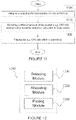
- FIGURE 12 illustrates an example virtual computing device 1200 for adaptively selecting a total number of CRC or PC bits, according to certain embodiments.
- virtual computing device 1200 may include modules for performing steps similar to those described above with regard to the method illustrated and described in FIGURE 11 .
- virtual computing device 1200 may include a selecting module 1210, an allocating module 1220, a placing module 1230, and any other suitable modules for adaptively selecting a total number of CRC or PC bits.
- one or more of the modules may be implemented using one or more processor(s) 28 of FIGURE 3 or one or more processors) 58 of FIGURE 6 .
- the functions of two or more of the various modules may be combined into a single module.
- the selecting module 1210 may perform the selecting functions of virtual computing device 1200. For example, in a particular embodiment, selecting module 1210 may adaptively select the total number of CRC or PC bits.
- the allocating module 1220 may perform the allocation functions of virtual computing device 1200. For example, in a particular embodiment, allocating module 1220 may allocate a different amount of the available CRC bits, for example, between error detection and error correction for Polar codes.
- the placing module 1230 may perform the placing functions of virtual computing device 1200. For example, in a particular embodiment, placing module 1230 may place the CRC bits, for example, within a code block.
- virtual computing device 1200 may include additional components beyond those shown in FIGURE 12 that may be responsible for providing certain aspects of the functionality, including any of the functionality described above and/or any additional functionality (including any functionality necessary to support the solutions described above).
- the various different types of devices and radio nodes may include components having the same physical hardware but configured (e.g., via programming) to support different radio access technologies, or may represent partly or entirely different physical components.
- FIGURE 13 illustrates an example method 1300 by a transmitter for adaptively generating precoder bits for a Polar code, according to certain embodiments.
- the transmitter may be a wireless device such as wireless device 56, described above.
- the transmitter may be a network node such as radio access node 24 or another network node.
- the precoder bits may include CRC bits or PC bits.
- the method begins at step 1310 when the transmitter acquires at least one configuration parameter upon which a total number of precoder bits depends.
- the transmitter determines the total number of precoder bits.
- the transmitter may allocate a first number of the available precoder bits (L d ) to error detection and a second number of the available precoder bits (L c ) to error correction.
- the first number of the available precoder bits (L d ) may be a minimum number of precoder bits (L d,0 ) associated with a minimum level of error detection for a number of info bits and the second number of the available precoder bits (L c ) may be determined by subtracting the first number of available precoder bits (L d ) from a total number of available precoder bits (L total ).
- the first number of the available precoder bits (L d ) allocated to error detection may be greater than a minimum number of precoder bits (L d,0 ) associated with a minimum level of error detection to provide increased error detection capability.
- the transmitter may determine the total number of precoder bits by performing one of:
- L d ,0 L d ,1 ⁇ L d ,2 ⁇ L d ,3 , and L c , 1 > L c , 2 > L c , 3 .
- the transmitter generates the precoder bits for a code block according to the determined total number of precoder bits.
- the precoder bits may be generated based on at least one of latency requirements, reliability requirements, wireless channel conditions as indicated by a target code rate, and available radio resources as indicated by a code length.
- the precoder bits are CRC bits, for example, the CRC bits may be generated using a single CRC generated polynomial, in a particular embodiment. In another particular embodiment, the CRC bits may be generated using two or more CRC generated polynomials.
- the transmitter places the precoder bits within the code block.
- the transmitter may place the precoder bits in the code block as a contiguous block.
- the transmitter may use an interleaver to place the precoder bits at interleaved positions within the code block.
- FIGURE 14 illustrates an example virtual computing device 1400 for adaptively generating precoder bits for a Polar code, according to certain embodiments.
- virtual computing device 1400 may include modules for performing steps similar to those described above with regard to the method 1300 illustrated and described in FIGURE 13 .
- virtual computing device 1400 may include at least one acquiring module 1410, a determining module 1420, a generating module 1430, a placing module 1440, and any other suitable modules for adaptively generating precoder bits for a Polar code.
- one or more of the modules may be implemented using one or more processors 28 of FIGURE 3 or one or more processors 58 of FIGURE 6 .
- the functions of two or more of the various modules may be combined into a single module.
- the acquiring module 1410 may perform the acquiring functions of virtual computing device 1400. For example, in a particular embodiment, acquiring module 1410 may aquire at least one configuration parameter upon which a total number of precoder bits depends.
- the determining module 1420 may perform the determining functions of virtual computing device 1400. For example, in a particular embodiment, determining module 1420 may determine the total number of precoder bits.
- the generating module 1430 may perform the generating functions of virtual computing device 1400. For example, in a particular embodiment, generating module 1430 may generate the precoder bits for a code block according to the determined total number of precoder bits.
- the placing module 1440 may perform the placinging functions of virtual computing device 1400. For example, in a particular embodiment, placing module 1440 may place the precoder bits within the code block.
- virtual computing device 1400 may include additional components beyond those shown in FIGURE 14 that may be responsible for providing certain aspects of the transmitter's functionality, including any of the functionality described above and/or any additional functionality (including any functionality necessary to support the solutions described above).
- the various different types of transmitters may include components having the same physical hardware but configured (e.g., via programming) to support different radio access technologies, or may represent partly or entirely different physical components.
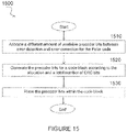
- FIGURE 15 illustrates another example method 1500 by a transmitter for adaptively generating precoder bits for a Polar code, according to certain embodiments.
- the transmitter may be a wireless device such as wireless device 56, described above.
- the transmitter may be a network node such as radio access node 24 or another network node.
- the precoder bits may include CRC bits or PC bits.
- the method begins at step 1510 when the transmitter allocates a different amount of available precoder bits between error detection and error correction for the Polar code.
- the precoder bits may be allocated based on at least one of latency requirements, reliability requirements, wireless channel conditions as indicated by a target code rate, and available radio resources as indicated by a code length.
- the transmitter may allocate a first number of the available precoder bits (L d ) to error detection and a second number of the available precoder bits (L c ) to error correction. 24.
- the first number of the available precoder bits (L d ) may be a minimum number of precoder bits (L d,0 ) associated with a minimum level of error detection for a number of info bits and the second number of the available precoder bits (L c ) is determined by subtracting the first number of available precoder bits (L d ) from a total number of available precoder bits (L total ), in a particular embodiment.
- the first number of the available precoder bits (L d ) allocated to error detection may be greater than a minimum number of precoder bits (L d,0 ) associated with a minimum level of error detection to provide increased error detection capability.
- the transmitter may determine the total number of precoder bits by performing one of:
- L d ,0 L d , 1 ⁇ L d , 2 ⁇ L d , 3
- L c L c , 1 > L c , 2 > L c , 3 .
- the transmitter generates the precoder bits for a code block according to the allocation and a total number of CRC bits.
- the CRC bits may be generated using a single CRC generated polynomial.
- the CRC bits may be generated using two or more CRC generated polynomials.
- the transmitter places the precoder bits within the code block.
- the transmitter may place the precoder bits in the code block as a contiguous block.
- the transmitter may use an interleaver to place the precoder bits at interleaved positions within the code block.
- FIGURE 16 illustrates an example virtual computing device 1600 for adaptively generating precoder bits for a Polar code, according to certain embodiments.
- virtual computing device 1600 may include modules for performing steps similar to those described above with regard to the method 1500 illustrated and described in FIGURE 15 .
- virtual computing device 1600 may include at least one allocating module 1610, a generating module 1620, a placing module 1630, and any other suitable modules for adaptively generating precoder bits for a Polar code.
- one or more of the modules may be implemented using one or more processors 28 of FIGURE 3 or one or more processors 58 of FIGURE 6 .
- the functions of two or more of the various modules may be combined into a single module.
- the allocating module 1610 may perform the allocating functions of virtual computing device 1600. For example, in a particular embodiment, allocating module 1610 may allocate a different amount of available precoder bits between error detection and error correction for the Polar code.
- the generating module 1620 may perform the generating functions of virtual computing device 1600. For example, in a particular embodiment, generating module 1620 may generate the precoder bits for a code block according to the allocation and a total number of CRC bits.
- the placing module 1630 may perform the placinging functions of virtual computing device 1600. For example, in a particular embodiment, placing module 1630 may place the precoder bits within the code block.
- virtual computing device 1600 may include additional components beyond those shown in FIGURE 16 that may be responsible for providing certain aspects of the transmitter's functionality, including any of the functionality described above and/or any additional functionality (including any functionality necessary to support the solutions described above).
- the various different types of transmitters may include components having the same physical hardware but configured (e.g., via programming) to support different radio access technologies, or may represent partly or entirely different physical components.
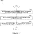
- FIGURE 17 illustrates an example method 1700 by a receiver for adaptively using precoder bits to assist decoding of a Polar code, according to certain embodiments.
- the receiver may be a wireless device such as wireless device 56, described above.
- the receiver may be a network node such as radio access node 24 or another network node.
- the precoder bits may include CRC bits or PC bits.
- the method begins at step 1710 when the receiver allocates a different amount of available precoder bits between error detection and error correction for a Polar code.
- the precoder bits may be allocated based on at least one of latency requirements, reliability requirements, wireless channel conditions as indicated by a target code rate, and available radio resources as indicated by a code length.
- the receiver may allocate a first number of the available precoder bits (L d ) to error detection and a second number of the available precoder bits (L c ) to error correction. 24.
- the first number of the available precoder bits (L d ) may be a minimum number of precoder bits (L d,0 ) associated with a minimum level of error detection for a number of info bits and the second number of the available precoder bits (L c ) may be determined by subtracting the first number of available precoder bits (L d ) from a total number of available precoder bits (L total ), in a particular embodiment.
- the first number of the available precoder bits (L d ) allocated to error detection may be greater than a minimum number of precoder bits (L d,0 ) associated with a minimum level of error detection to provide increased error detection capability.
- the receiver when allocating the precoder bits, the receiver may perform one of the following steps:
- the receiver uses the precoder bits allocated for error correction to assist decoding of a code block. After decoding the code block, the receiver uses the precoder bits allocated for error detection to perform error detection on the decoded bits, at step 1730.
- the method may further include the receiver receiving, from a transmitter, an indication of the different amount of available precoder bits for allocation between error detection and error correction for the Polar codes.
- the receiver may perform the allocation step 1710 based on the indication.
- the method for adaptively using precoder bits to assist decoding of a Polar code as described above may be performed by a virtual computing device.
- FIGURE 18 illustrates an example virtual computing device 1800 for adaptively using precoder bits to assist decoding of a Polar code, according to certain embodiments.
- virtual computing device 1800 may include modules for performing steps similar to those described above with regard to the method 1700 illustrated and described in FIGURE 17 .
- virtual computing device 1800 may include at least one allocating module 1810, a first using module 1820, a second using module 1830, and any other suitable modules for adaptively using precoder bits to assist decoding of a Polar code.
- one or more of the modules may be implemented using one or more processors 28 of FIGURE 3 or one or more processors 58 of FIGURE 6 .
- the functions of two or more of the various modules may be combined into a single module.
- the allocating module 1810 may perform the allocating functions of virtual computing device 1800. For example, in a particular embodiment, allocating module 1810 may allocate a different amount of available precoder bits between error detection and error correction for a Polar code.
- the first using module 1820 may perform certain of the using functions of virtual computing device 1800. For example, in a particular embodiment, first using module 1820 may use the precoder bits allocated for error correction to assist decoding of a code block.
- the second using module 1830 may perform certain other of the using functions of virtual computing device 1800. For example, in a particular embodiment, second using module 1830 may use the precoder bits allocated for error detection to perform error detection on the decoded bits.
- virtual computing device 1800 may include additional components beyond those shown in FIGURE 18 that may be responsible for providing certain aspects of the receiver's functionality, including any of the functionality described above and/or any additional functionality (including any functionality necessary to support the solutions described above).
- the various different types of receivers may include components having the same physical hardware but configured (e.g., via programming) to support different radio access technologies, or may represent partly or entirely different physical components.
- methods, systems and apparatus are disclosed for adaptively selecting the total number of CRC or PC bits, allocating a different amount of the available CRC bits between error detection and error correction for Polar codes, and placing the CRC bits within a code block.
- various balances of error correction and error detection capabilities can be achieved in the SCL decoder.
- the features described allow the concatenation of CRC and PC code to be customized for different amounts of payloads, different coding parameters needed for the varying communication channel conditions, and different types of applications with different requirements in terms of, for example, latency and reliability.
- the foregoing features may be based on the requirements (e.g. latency or reliability) of the underlying application, the wireless channel conditions as indicated by the target code rate, and/or the available radio resources as indicated by the code length.
- the precoder bits can be CRC bits. According to an alternative embodiment, the precoder bits are parity-checksum (PC) bits.
- PC parity-checksum
- an advantage of features herein is to allow the concatenation of CRC code to be customized for different amounts of payloads, different coding parameters needed for the varying communication channel conditions, and different types of applications with different requirements in terms of, for example, latency and reliability. Since 5G wireless communications need to cover a wide range of circumstances and applications, embodiments of this disclosure allow the system to judiciously allocate radio resources based on cost-benefit tradeoffs.
Landscapes
- Engineering & Computer Science (AREA)
- Physics & Mathematics (AREA)
- Probability & Statistics with Applications (AREA)
- Theoretical Computer Science (AREA)
- Computer Networks & Wireless Communication (AREA)
- Signal Processing (AREA)
- Mathematical Physics (AREA)
- Mobile Radio Communication Systems (AREA)
- Detection And Prevention Of Errors In Transmission (AREA)
- Error Detection And Correction (AREA)
Claims (14)
- Procédé par un émetteur (24, 56) pour la génération adaptative d'un nombre total de bits de précodeur pour un code polaire, le procédé comprenant :l'acquisition d'au moins un paramètre de configuration duquel dépend le nombre total de bits de précodeur pour le code polaire, l'au moins un paramètre de configuration comprenant une longueur de bloc d'informations K, les bits de précodeur étant tous des bits de précodeur de contrôle de redondance cyclique, CRC, ou étant tous des bits de précodeur de contrôle de parité, PC ;la détermination du nombre total de bits de précodeur sur la base de l'au moins un paramètre de configuration, et l'allocation des bits de précodeur pour équilibrer des capacités de détection d'erreur et de correction d'erreur du code polaire, dans lequel la détermination du nombre total de bits de précodeur comprend :l'allocation d'un nombre donné des bits de précodeur disponibles à une détection d'erreur ; etl'allocation d'un autre nombre donné des bits de précodeur disponibles à une correction d'erreur ;la génération des bits de précodeur pour un bloc de code en fonction du nombre total déterminé des bits de précodeur et de l'allocation des bits de précodeur ; etle placement des bits de précodeur à l'intérieur du bloc de code,dans lequel, à la détermination du nombre total de bits de précodeur, l'allocation de bits de précodeur pour équilibrer des capacités de détection d'erreur et de correction d'erreur du code polaire comprend l'une parmi :l'allocation, en tant que le nombre donné, d'un premier nombre des bits de précodeur disponibles Ld,1 à une détection d'erreur et, en tant que l'autre nombre donné, d'un deuxième nombre des bits de précodeur disponibles Lc,1 à une correction d'erreur pour une première capacité de détection d'erreur et une première capacité de correction d'erreur ; oul'allocation, en tant que le nombre donné, d'un troisième nombre des bits de précodeur disponibles Ld,2 à une détection d'erreur et, en tant que l'autre nombre donné, d'un quatrième nombre des bits de précodeur disponibles Lc,2 à une correction d'erreur pour une deuxième capacité de détection d'erreur et une deuxième capacité de correction d'erreur ; oul'allocation, en tant que le nombre donné, d'un cinquième nombre des bits de précodeur disponibles Ld,3 à une détection d'erreur et, en tant que l'autre nombre donné, d'un sixième nombre des bits de précodeur disponibles Lc,3 à une correction d'erreur pour une troisième capacité de détection d'erreur et une troisième capacité de correction d'erreur,dans lequel la première capacité de détection d'erreur est inférieure à la deuxième capacité de détection d'erreur, la deuxième capacité de détection d'erreur est inférieure à la troisième capacité de détection d'erreur, la première capacité de correction d'erreur est supérieure à la deuxième capacité de correction d'erreur, et la deuxième capacité de correction d'erreur est supérieure à la troisième capacité de correction d'erreur ; etdans lequel, pour un nombre minimal de bits de précodeur Ld,0 associé à un niveau minimal de détection d'erreur pour fournir une capacité de détection d'erreur accrue,ce qui suit est vrai :


- Procédé selon la revendication 1, dans lequel le placement des bits de précodeur à l'intérieur du bloc de code comprend le placement des bits de précodeur à des positions entrelacées par l'utilisation d'un entrelaceur.
- Procédé selon la revendication 1 ou 2, dans lequel l'étape de la génération des bits de précodeur est basée sur au moins l'une parmi :exigences de latence ;exigences de fiabilité ;conditions de canal sans fil telles qu'indiquées par un débit de code cible ; etressources radio disponibles telles qu'indiquées par une longueur de code.
- Procédé selon l'une quelconque des revendications 1 à 3, dans lequel les bits de précodeur sont des bits de CRC.
- Procédé selon la revendication 4, dans lequel la génération des bits de précodeur comprend la génération de bits de CRC en utilisant un polynôme générateur de CRC unique, ou dans lequel la génération des bits de précodeur comprend la génération des bits de CRC en utilisant deux polynômes générateurs de CRC ou plus.
- Procédé selon l'une quelconque des revendications 1 à 3, dans lequel les bits de précodeur sont des bits de PC.
- Procédé selon l'une quelconque des revendications 1 à 6, dans lequel soit l'émetteur comprend un dispositif sans fil (56) soit l'émetteur comprend un nœud de réseau (24) .
- Emetteur (24, 56) pour la génération adaptative d'un nombre total de bits de précodeur pour un code polaire, l'émetteur comprenant :au moins un processeur (58) configuré pour :
acquérir au moins un paramètre de configuration duquel dépend le nombre total de bits de précodeur, l'au moins un paramètre de configuration comprenant une longueur de bloc d'informations K, les bits de précodeur étant tous des bits de précodeur de contrôle de redondance cyclique, CRC, ou étant tous des bits de précodeur de contrôle de parité, PC ;déterminer le nombre total de bits de précodeur sur la base de l'au moins un paramètre de configuration, et allouer les bits de précodeur pour équilibrer des capacités de détection d'erreur et de correction d'erreur du code polaire, dans lequel l'au moins un processeur (58) est en outre configuré pour déterminer le nombre total de bits de précodeur par :l'allocation d'un nombre donné des bits de précodeur disponibles à une détection d'erreur ; etl'allocation d'un autre nombre donné des bits de précodeur disponibles à une correction d'erreur ;générer les bits de précodeur pour un bloc de code en fonction du nombre total déterminé des bits de précodeur et de l'allocation des bits de précodeur ; etplacer les bits de précodeur à l'intérieur du bloc de code,dans lequel, lors de l'allocation de bits de précodeur pour équilibrer des capacités de détection d'erreur et de correction d'erreur du code polaire à la détermination du nombre total de bits de précodeur, l'au moins un processeur est configuré pour :allouer, en tant que le nombre donné, un premier nombre des bits de précodeur disponibles Ld,1 à une détection d'erreur et, en tant que l'autre nombre donné, un deuxième nombre des bits de précodeur disponibles Lc,1 à une correction d'erreur pour une première capacité de détection d'erreur et une première capacité de correction d'erreur ; ouallouer, en tant que le nombre donné, un troisième nombre des bits de précodeur disponibles Ld,2 à une détection d'erreur et, en tant que l'autre nombre donné, un quatrième nombre des bits de précodeur disponibles Lc,2 à une correction d'erreur pour une deuxième capacité de détection d'erreur et une deuxième capacité de correction d'erreur ; ou allouer, en tant que le nombre donné, un cinquième nombre des bits de précodeur disponibles Ld,3 à une détection d'erreur et, en tant que l'autre nombre donné, un sixième nombre des bits de précodeur disponibles Lc,3 à une correction d'erreur pour une troisième capacité de détection d'erreur et une troisième capacité de correction d'erreur,dans lequel la première capacité de détection d'erreur est inférieure à la deuxième capacité de détection d'erreur, la deuxième capacité de détection d'erreur est inférieure à la troisième capacité de détection d'erreur, la première capacité de correction d'erreur est supérieure à la deuxième capacité de correction d'erreur, et la deuxième capacité de correction d'erreur est supérieure à la troisième capacité de correction d'erreur ; etdans lequel, pour un nombre minimal de bits de précodeur Ld,0 associé à un niveau minimal de détection d'erreur pour fournir une capacité de détection d'erreur accrue, ce qui suit est vrai :

- Emetteur (24, 56) selon la revendication 8, dans lequel, lors du placement des bits de précodeur à l'intérieur du bloc de code, l'au moins un processeur (58) est configuré pour placer les bits de précodeur à des positions entrelacées par l'utilisation d'un entrelaceur.
- Emetteur (24, 56) selon la revendication 8 ou 9, dans lequel les bits de précodeur sont générés sur la base d'au moins l'une parmi :exigences de latence ;exigences de fiabilité ;conditions de canal sans fil telles qu'indiquées par un débit de code cible ; etressources radio disponibles telles qu'indiquées par une longueur de code.
- Emetteur (24, 56) selon l'une quelconque des revendications 8 à 10, dans lequel les bits de précodeur sont des bits de CRC.
- Emetteur (24, 56) selon la revendication 11, dans lequel l'au moins un processeur (58) est configuré pour générer les bits de CRC en utilisant un polynôme générateur de CRC unique, ou dans lequel l'au moins un processeur (58) est configuré pour générer les bits de CRC en utilisant deux polynômes générateurs de CRC ou plus.
- Emetteur (24, 56) selon l'une quelconque des revendications 8 à 10, dans lequel les bits de précodeur sont des bits de PC.
- Emetteur (24) selon l'une quelconque des revendications 8 à 13, dans lequel soit l'émetteur comprend un dispositif sans fil (24) soit l'émetteur comprend un nœud de réseau (56).
Applications Claiming Priority (2)
| Application Number | Priority Date | Filing Date | Title |
|---|---|---|---|
| US201762455128P | 2017-02-06 | 2017-02-06 | |
| PCT/IB2018/050734 WO2018142374A1 (fr) | 2017-02-06 | 2018-02-06 | Code polaire concaténé avec détection d'erreur adaptative |
Publications (2)
| Publication Number | Publication Date |
|---|---|
| EP3549292A1 EP3549292A1 (fr) | 2019-10-09 |
| EP3549292B1 true EP3549292B1 (fr) | 2022-04-06 |
Family
ID=61526838
Family Applications (1)
| Application Number | Title | Priority Date | Filing Date |
|---|---|---|---|
| EP18708205.2A Active EP3549292B1 (fr) | 2017-02-06 | 2018-02-06 | Code polaire concaténé avec détection d'erreur adaptative |
Country Status (11)
| Country | Link |
|---|---|
| US (3) | US11165445B2 (fr) |
| EP (1) | EP3549292B1 (fr) |
| JP (1) | JP7064500B2 (fr) |
| CN (1) | CN110268653B (fr) |
| BR (1) | BR112019016212A2 (fr) |
| CA (1) | CA3050076C (fr) |
| ES (1) | ES2917025T3 (fr) |
| MX (1) | MX2019009267A (fr) |
| RU (1) | RU2733818C1 (fr) |
| WO (1) | WO2018142374A1 (fr) |
| ZA (1) | ZA201904135B (fr) |
Families Citing this family (11)
| Publication number | Priority date | Publication date | Assignee | Title |
|---|---|---|---|---|
| CN110268653B (zh) * | 2017-02-06 | 2022-03-22 | 瑞典爱立信有限公司 | 具有自适应错误检测的级联极化码 |
| US11740970B2 (en) * | 2020-03-02 | 2023-08-29 | Micron Technology, Inc. | Dynamic adjustment of data integrity operations of a memory system based on error rate classification |
| US11221800B2 (en) | 2020-03-02 | 2022-01-11 | Micron Technology, Inc. | Adaptive and/or iterative operations in executing a read command to retrieve data from memory cells |
| US11029890B1 (en) | 2020-03-02 | 2021-06-08 | Micron Technology, Inc. | Compound feature generation in classification of error rate of data retrieved from memory cells |
| US11086572B1 (en) | 2020-03-02 | 2021-08-10 | Micron Technology, Inc. | Self adapting iterative read calibration to retrieve data from memory cells |
| US11562793B2 (en) | 2020-05-07 | 2023-01-24 | Micron Technology, Inc. | Read soft bits through boosted modulation following reading hard bits |
| US11081200B1 (en) | 2020-05-07 | 2021-08-03 | Micron Technology, Inc. | Intelligent proactive responses to operations to read data from memory cells |
| US11830545B2 (en) | 2020-12-16 | 2023-11-28 | Micron Technology, Inc. | Data programming techniques to store multiple bits of data per memory cell with high reliability |
| US20240056102A1 (en) * | 2021-01-04 | 2024-02-15 | Nippon Telegraph And Telephone Corporation | Decoding apparatus, decoding method and program |
| CN113676288B (zh) * | 2021-07-27 | 2022-06-24 | 中国地质大学(武汉) | 一种用于极化码串行抵消列表译码器的译码值复制方法 |
| US20230361788A1 (en) * | 2022-05-04 | 2023-11-09 | Qualcomm Incorporated | Polarization adjusted channel coding design for complexity reduction |
Citations (1)
| Publication number | Priority date | Publication date | Assignee | Title |
|---|---|---|---|---|
| US20190068225A1 (en) * | 2016-04-29 | 2019-02-28 | Huawei Technologies Co., Ltd. | Polar Polar Code Encoding And Decoding Method And Apparatus |
Family Cites Families (24)
| Publication number | Priority date | Publication date | Assignee | Title |
|---|---|---|---|---|
| CN101076176A (zh) | 2006-05-16 | 2007-11-21 | 大唐移动通信设备有限公司 | 移动通信系统中分配用户设备业务资源的方法 |
| CN101536406B (zh) | 2006-10-31 | 2014-12-24 | 艾利森电话股份有限公司 | 电信系统中的方法和设备 |
| CN100579316C (zh) | 2007-02-15 | 2010-01-06 | 大唐移动通信设备有限公司 | 多媒体广播和组播业务中载波迁移的方法和装置 |
| CN101262635B (zh) | 2007-03-09 | 2010-09-29 | 中兴通讯股份有限公司 | 一种在多载波小区实现增强mbms业务的方法 |
| CN101296028B (zh) | 2007-04-25 | 2012-11-21 | 大唐移动通信设备有限公司 | 专用载波传输多媒体广播组播业务方法与装置及传输系统 |
| JP5232420B2 (ja) * | 2007-08-17 | 2013-07-10 | 株式会社エヌ・ティ・ティ・ドコモ | データ送信方法、データ受信方法、移動端末及び無線通信システム |
| US8375271B2 (en) * | 2007-10-26 | 2013-02-12 | Telefonaktiebolaget L M Ericsson (Publ) | Method and apparatus for providing adaptive cyclic redundancy check computation |
| US8201069B2 (en) * | 2008-07-01 | 2012-06-12 | International Business Machines Corporation | Cyclical redundancy code for use in a high-speed serial link |
| EP2398179B1 (fr) * | 2010-06-11 | 2017-03-22 | Intel Deutschland GmbH | Procédé pour détecter la validité d'informations de contrôle en liaison descendante dans un équipement d'utilisateur en télécommunications et récepteur de bande de base pour le réaliser |
| KR101951663B1 (ko) * | 2012-12-14 | 2019-02-25 | 삼성전자주식회사 | Crc 부호와 극 부호에 의한 부호화 방법 및 장치 |
| CN104219019B (zh) * | 2013-05-31 | 2021-06-22 | 华为技术有限公司 | 编码方法及编码设备 |
| CN109861694B (zh) | 2013-11-20 | 2021-10-26 | 华为技术有限公司 | 极化码的处理方法和设备 |
| RU2637476C1 (ru) * | 2014-02-21 | 2017-12-04 | Хуавэй Текнолоджиз Ко., Лтд. | Способ и устройство согласования скорости для полярного кода |
| RU2014110139A (ru) * | 2014-03-17 | 2015-09-27 | ЭлЭсАй Корпорейшн | Полярные коды произвольной длины |
| US9571231B2 (en) * | 2014-08-21 | 2017-02-14 | Rambus Inc. | In-band status encoding and decoding using error correction symbols |
| CN105227189B (zh) * | 2015-09-24 | 2019-01-01 | 电子科技大学 | 分段crc辅助的极化码编译码方法 |
| US9917675B2 (en) * | 2016-06-01 | 2018-03-13 | Qualcomm Incorporated | Enhanced polar code constructions by strategic placement of CRC bits |
| EP3832922A1 (fr) * | 2016-07-15 | 2021-06-09 | Sharp Kabushiki Kaisha | Appareil de transmission, appareil de réception, procédé de transmission et procédé de réception |
| CN109661787A (zh) * | 2016-08-10 | 2019-04-19 | Idac控股公司 | 用于控制信息的基于优先级的信道编码 |
| WO2018058352A1 (fr) * | 2016-09-28 | 2018-04-05 | Qualcomm Incorporated | Mappage de sous-canaux |
| US10849012B2 (en) * | 2016-12-02 | 2020-11-24 | Lg Electronics Inc. | Method for performing decoding by terminal and terminal for performing same method |
| US10348328B2 (en) * | 2017-01-06 | 2019-07-09 | At&T Intellectual Property I, L.P. | Reducing control channel overhead using polar codes |
| EP3577808A1 (fr) * | 2017-02-03 | 2019-12-11 | IDAC Holdings, Inc. | Codes polaires évolués pour canal de commande |
| CN110268653B (zh) * | 2017-02-06 | 2022-03-22 | 瑞典爱立信有限公司 | 具有自适应错误检测的级联极化码 |
-
2018
- 2018-02-06 CN CN201880010512.2A patent/CN110268653B/zh active Active
- 2018-02-06 MX MX2019009267A patent/MX2019009267A/es unknown
- 2018-02-06 CA CA3050076A patent/CA3050076C/fr active Active
- 2018-02-06 EP EP18708205.2A patent/EP3549292B1/fr active Active
- 2018-02-06 RU RU2019127915A patent/RU2733818C1/ru active
- 2018-02-06 ES ES18708205T patent/ES2917025T3/es active Active
- 2018-02-06 JP JP2019542449A patent/JP7064500B2/ja active Active
- 2018-02-06 BR BR112019016212A patent/BR112019016212A2/pt unknown
- 2018-02-06 US US16/483,188 patent/US11165445B2/en active Active
- 2018-02-06 WO PCT/IB2018/050734 patent/WO2018142374A1/fr unknown
-
2019
- 2019-06-25 ZA ZA2019/04135A patent/ZA201904135B/en unknown
-
2021
- 2021-09-29 US US17/488,531 patent/US11824561B2/en active Active
-
2023
- 2023-10-12 US US18/485,381 patent/US20240039560A1/en active Pending
Patent Citations (1)
| Publication number | Priority date | Publication date | Assignee | Title |
|---|---|---|---|---|
| US20190068225A1 (en) * | 2016-04-29 | 2019-02-28 | Huawei Technologies Co., Ltd. | Polar Polar Code Encoding And Decoding Method And Apparatus |
Non-Patent Citations (3)
| Title |
|---|
| INTEL CORPORATION: "Polar code design", vol. RAN WG1, no. Spokane, USA; 20170116 - 20170120, 10 January 2017 (2017-01-10), XP051202864, Retrieved from the Internet <URL:http://www.3gpp.org/ftp/tsg_ran/WG1_RL1/TSGR1_AH/NR_AH_1701/Docs/> [retrieved on 20170110] * |
| INTEL: "Considerations in Polar code design", vol. RAN WG1, no. Spokane, USA; 20170116 - 20170120, 16 January 2017 (2017-01-16), XP051207922, Retrieved from the Internet <URL:http://www.3gpp.org/ftp/Meetings_3GPP_SYNC/RAN1/Docs/> [retrieved on 20170116] * |
| QUALCOMM INCORPORATED: "Design of Polar codes for control channel", vol. RAN WG1, no. Spokane, USA; 20170116 - 20170120, 16 January 2017 (2017-01-16), XP051208351, Retrieved from the Internet <URL:http://www.3gpp.org/ftp/Meetings_3GPP_SYNC/RAN1/Docs/> [retrieved on 20170116] * |
Also Published As
| Publication number | Publication date |
|---|---|
| RU2733818C1 (ru) | 2020-10-07 |
| CN110268653B (zh) | 2022-03-22 |
| MX2019009267A (es) | 2019-09-10 |
| ES2917025T3 (es) | 2022-07-06 |
| CN110268653A (zh) | 2019-09-20 |
| JP7064500B2 (ja) | 2022-05-10 |
| US20220021402A1 (en) | 2022-01-20 |
| US11165445B2 (en) | 2021-11-02 |
| WO2018142374A1 (fr) | 2018-08-09 |
| BR112019016212A2 (pt) | 2020-04-07 |
| US11824561B2 (en) | 2023-11-21 |
| ZA201904135B (en) | 2021-10-27 |
| CA3050076A1 (fr) | 2018-08-09 |
| US20240039560A1 (en) | 2024-02-01 |
| US20190379404A1 (en) | 2019-12-12 |
| JP2020509660A (ja) | 2020-03-26 |
| EP3549292A1 (fr) | 2019-10-09 |
| CA3050076C (fr) | 2022-08-30 |
Similar Documents
| Publication | Publication Date | Title |
|---|---|---|
| EP3549292B1 (fr) | Code polaire concaténé avec détection d'erreur adaptative | |
| US11191065B2 (en) | Coding technique for multi-stage control information | |
| US11831428B2 (en) | Adaptation of the CRC code length for 3GPP NR | |
| US11165442B2 (en) | CRC interleaving pattern for polar codes | |
| US20200235852A1 (en) | Enhanced Information Sequences for Polar Codes | |
| US11159179B2 (en) | Enhanced information sequences for polar codes | |
| US11152959B2 (en) | Enhanced information sequences for polar codes | |
| US11515894B2 (en) | Enhanced information sequences for polar codes | |
| OA19671A (en) | Concatenated polar code with adaptive error detection. | |
| WO2023237913A1 (fr) | Multiplexage d'uci et de données sur de petites attributions de pusch satisfaisant un seuil de débit de code |
Legal Events
| Date | Code | Title | Description |
|---|---|---|---|
| STAA | Information on the status of an ep patent application or granted ep patent |
Free format text: STATUS: UNKNOWN |
|
| STAA | Information on the status of an ep patent application or granted ep patent |
Free format text: STATUS: THE INTERNATIONAL PUBLICATION HAS BEEN MADE |
|
| PUAI | Public reference made under article 153(3) epc to a published international application that has entered the european phase |
Free format text: ORIGINAL CODE: 0009012 |
|
| STAA | Information on the status of an ep patent application or granted ep patent |
Free format text: STATUS: REQUEST FOR EXAMINATION WAS MADE |
|
| 17P | Request for examination filed |
Effective date: 20190701 |
|
| AK | Designated contracting states |
Kind code of ref document: A1 Designated state(s): AL AT BE BG CH CY CZ DE DK EE ES FI FR GB GR HR HU IE IS IT LI LT LU LV MC MK MT NL NO PL PT RO RS SE SI SK SM TR |
|
| AX | Request for extension of the european patent |
Extension state: BA ME |
|
| STAA | Information on the status of an ep patent application or granted ep patent |
Free format text: STATUS: EXAMINATION IS IN PROGRESS |
|
| 17Q | First examination report despatched |
Effective date: 20191114 |
|
| DAV | Request for validation of the european patent (deleted) | ||
| DAX | Request for extension of the european patent (deleted) | ||
| STAA | Information on the status of an ep patent application or granted ep patent |
Free format text: STATUS: EXAMINATION IS IN PROGRESS |
|
| GRAP | Despatch of communication of intention to grant a patent |
Free format text: ORIGINAL CODE: EPIDOSNIGR1 |
|
| STAA | Information on the status of an ep patent application or granted ep patent |
Free format text: STATUS: GRANT OF PATENT IS INTENDED |
|
| INTG | Intention to grant announced |
Effective date: 20210602 |
|
| GRAJ | Information related to disapproval of communication of intention to grant by the applicant or resumption of examination proceedings by the epo deleted |
Free format text: ORIGINAL CODE: EPIDOSDIGR1 |
|
| STAA | Information on the status of an ep patent application or granted ep patent |
Free format text: STATUS: EXAMINATION IS IN PROGRESS |
|
| INTC | Intention to grant announced (deleted) | ||
| GRAP | Despatch of communication of intention to grant a patent |
Free format text: ORIGINAL CODE: EPIDOSNIGR1 |
|
| STAA | Information on the status of an ep patent application or granted ep patent |
Free format text: STATUS: GRANT OF PATENT IS INTENDED |
|
| INTG | Intention to grant announced |
Effective date: 20210910 |
|
| GRAS | Grant fee paid |
Free format text: ORIGINAL CODE: EPIDOSNIGR3 |
|
| GRAA | (expected) grant |
Free format text: ORIGINAL CODE: 0009210 |
|
| STAA | Information on the status of an ep patent application or granted ep patent |
Free format text: STATUS: THE PATENT HAS BEEN GRANTED |
|
| AK | Designated contracting states |
Kind code of ref document: B1 Designated state(s): AL AT BE BG CH CY CZ DE DK EE ES FI FR GB GR HR HU IE IS IT LI LT LU LV MC MK MT NL NO PL PT RO RS SE SI SK SM TR |
|
| REG | Reference to a national code |
Ref country code: GB Ref legal event code: FG4D |
|
| REG | Reference to a national code |
Ref country code: CH Ref legal event code: EP |
|
| REG | Reference to a national code |
Ref country code: AT Ref legal event code: REF Ref document number: 1482370 Country of ref document: AT Kind code of ref document: T Effective date: 20220415 |
|
| REG | Reference to a national code |
Ref country code: DE Ref legal event code: R096 Ref document number: 602018033327 Country of ref document: DE |
|
| REG | Reference to a national code |
Ref country code: IE Ref legal event code: FG4D |
|
| REG | Reference to a national code |
Ref country code: FI Ref legal event code: FGE |
|
| REG | Reference to a national code |
Ref country code: SE Ref legal event code: TRGR |
|
| REG | Reference to a national code |
Ref country code: NL Ref legal event code: FP |
|
| REG | Reference to a national code |
Ref country code: ES Ref legal event code: FG2A Ref document number: 2917025 Country of ref document: ES Kind code of ref document: T3 Effective date: 20220706 |
|
| REG | Reference to a national code |
Ref country code: LT Ref legal event code: MG9D |
|
| REG | Reference to a national code |
Ref country code: AT Ref legal event code: MK05 Ref document number: 1482370 Country of ref document: AT Kind code of ref document: T Effective date: 20220406 |
|
| PG25 | Lapsed in a contracting state [announced via postgrant information from national office to epo] |
Ref country code: PT Free format text: LAPSE BECAUSE OF FAILURE TO SUBMIT A TRANSLATION OF THE DESCRIPTION OR TO PAY THE FEE WITHIN THE PRESCRIBED TIME-LIMIT Effective date: 20220808 Ref country code: NO Free format text: LAPSE BECAUSE OF FAILURE TO SUBMIT A TRANSLATION OF THE DESCRIPTION OR TO PAY THE FEE WITHIN THE PRESCRIBED TIME-LIMIT Effective date: 20220706 Ref country code: LT Free format text: LAPSE BECAUSE OF FAILURE TO SUBMIT A TRANSLATION OF THE DESCRIPTION OR TO PAY THE FEE WITHIN THE PRESCRIBED TIME-LIMIT Effective date: 20220406 Ref country code: HR Free format text: LAPSE BECAUSE OF FAILURE TO SUBMIT A TRANSLATION OF THE DESCRIPTION OR TO PAY THE FEE WITHIN THE PRESCRIBED TIME-LIMIT Effective date: 20220406 Ref country code: GR Free format text: LAPSE BECAUSE OF FAILURE TO SUBMIT A TRANSLATION OF THE DESCRIPTION OR TO PAY THE FEE WITHIN THE PRESCRIBED TIME-LIMIT Effective date: 20220707 Ref country code: BG Free format text: LAPSE BECAUSE OF FAILURE TO SUBMIT A TRANSLATION OF THE DESCRIPTION OR TO PAY THE FEE WITHIN THE PRESCRIBED TIME-LIMIT Effective date: 20220706 Ref country code: AT Free format text: LAPSE BECAUSE OF FAILURE TO SUBMIT A TRANSLATION OF THE DESCRIPTION OR TO PAY THE FEE WITHIN THE PRESCRIBED TIME-LIMIT Effective date: 20220406 |
|
| PG25 | Lapsed in a contracting state [announced via postgrant information from national office to epo] |
Ref country code: RS Free format text: LAPSE BECAUSE OF FAILURE TO SUBMIT A TRANSLATION OF THE DESCRIPTION OR TO PAY THE FEE WITHIN THE PRESCRIBED TIME-LIMIT Effective date: 20220406 Ref country code: PL Free format text: LAPSE BECAUSE OF FAILURE TO SUBMIT A TRANSLATION OF THE DESCRIPTION OR TO PAY THE FEE WITHIN THE PRESCRIBED TIME-LIMIT Effective date: 20220406 Ref country code: LV Free format text: LAPSE BECAUSE OF FAILURE TO SUBMIT A TRANSLATION OF THE DESCRIPTION OR TO PAY THE FEE WITHIN THE PRESCRIBED TIME-LIMIT Effective date: 20220406 Ref country code: IS Free format text: LAPSE BECAUSE OF FAILURE TO SUBMIT A TRANSLATION OF THE DESCRIPTION OR TO PAY THE FEE WITHIN THE PRESCRIBED TIME-LIMIT Effective date: 20220806 |
|
| REG | Reference to a national code |
Ref country code: DE Ref legal event code: R097 Ref document number: 602018033327 Country of ref document: DE |
|
| PG25 | Lapsed in a contracting state [announced via postgrant information from national office to epo] |
Ref country code: SM Free format text: LAPSE BECAUSE OF FAILURE TO SUBMIT A TRANSLATION OF THE DESCRIPTION OR TO PAY THE FEE WITHIN THE PRESCRIBED TIME-LIMIT Effective date: 20220406 Ref country code: SK Free format text: LAPSE BECAUSE OF FAILURE TO SUBMIT A TRANSLATION OF THE DESCRIPTION OR TO PAY THE FEE WITHIN THE PRESCRIBED TIME-LIMIT Effective date: 20220406 Ref country code: RO Free format text: LAPSE BECAUSE OF FAILURE TO SUBMIT A TRANSLATION OF THE DESCRIPTION OR TO PAY THE FEE WITHIN THE PRESCRIBED TIME-LIMIT Effective date: 20220406 Ref country code: EE Free format text: LAPSE BECAUSE OF FAILURE TO SUBMIT A TRANSLATION OF THE DESCRIPTION OR TO PAY THE FEE WITHIN THE PRESCRIBED TIME-LIMIT Effective date: 20220406 Ref country code: DK Free format text: LAPSE BECAUSE OF FAILURE TO SUBMIT A TRANSLATION OF THE DESCRIPTION OR TO PAY THE FEE WITHIN THE PRESCRIBED TIME-LIMIT Effective date: 20220406 Ref country code: CZ Free format text: LAPSE BECAUSE OF FAILURE TO SUBMIT A TRANSLATION OF THE DESCRIPTION OR TO PAY THE FEE WITHIN THE PRESCRIBED TIME-LIMIT Effective date: 20220406 |
|
| PLBE | No opposition filed within time limit |
Free format text: ORIGINAL CODE: 0009261 |
|
| STAA | Information on the status of an ep patent application or granted ep patent |
Free format text: STATUS: NO OPPOSITION FILED WITHIN TIME LIMIT |
|
| 26N | No opposition filed |
Effective date: 20230110 |
|
| PG25 | Lapsed in a contracting state [announced via postgrant information from national office to epo] |
Ref country code: AL Free format text: LAPSE BECAUSE OF FAILURE TO SUBMIT A TRANSLATION OF THE DESCRIPTION OR TO PAY THE FEE WITHIN THE PRESCRIBED TIME-LIMIT Effective date: 20220406 |
|
| PGFP | Annual fee paid to national office [announced via postgrant information from national office to epo] |
Ref country code: FI Payment date: 20230223 Year of fee payment: 6 Ref country code: ES Payment date: 20230301 Year of fee payment: 6 |
|
| PG25 | Lapsed in a contracting state [announced via postgrant information from national office to epo] |
Ref country code: SI Free format text: LAPSE BECAUSE OF FAILURE TO SUBMIT A TRANSLATION OF THE DESCRIPTION OR TO PAY THE FEE WITHIN THE PRESCRIBED TIME-LIMIT Effective date: 20220406 |
|
| PGFP | Annual fee paid to national office [announced via postgrant information from national office to epo] |
Ref country code: SE Payment date: 20230227 Year of fee payment: 6 Ref country code: IT Payment date: 20230221 Year of fee payment: 6 Ref country code: GB Payment date: 20230227 Year of fee payment: 6 Ref country code: DE Payment date: 20230223 Year of fee payment: 6 |
|
| P01 | Opt-out of the competence of the unified patent court (upc) registered |
Effective date: 20230517 |
|
| PG25 | Lapsed in a contracting state [announced via postgrant information from national office to epo] |
Ref country code: MC Free format text: LAPSE BECAUSE OF FAILURE TO SUBMIT A TRANSLATION OF THE DESCRIPTION OR TO PAY THE FEE WITHIN THE PRESCRIBED TIME-LIMIT Effective date: 20220406 |
|
| REG | Reference to a national code |
Ref country code: CH Ref legal event code: PL |
|
| REG | Reference to a national code |
Ref country code: BE Ref legal event code: MM Effective date: 20230228 |
|
| PG25 | Lapsed in a contracting state [announced via postgrant information from national office to epo] |
Ref country code: LU Free format text: LAPSE BECAUSE OF NON-PAYMENT OF DUE FEES Effective date: 20230206 Ref country code: LI Free format text: LAPSE BECAUSE OF NON-PAYMENT OF DUE FEES Effective date: 20230228 Ref country code: CH Free format text: LAPSE BECAUSE OF NON-PAYMENT OF DUE FEES Effective date: 20230228 |
|
| REG | Reference to a national code |
Ref country code: IE Ref legal event code: MM4A |
|
| PG25 | Lapsed in a contracting state [announced via postgrant information from national office to epo] |
Ref country code: IE Free format text: LAPSE BECAUSE OF NON-PAYMENT OF DUE FEES Effective date: 20230206 Ref country code: FR Free format text: LAPSE BECAUSE OF NON-PAYMENT OF DUE FEES Effective date: 20230228 |
|
| PG25 | Lapsed in a contracting state [announced via postgrant information from national office to epo] |
Ref country code: BE Free format text: LAPSE BECAUSE OF NON-PAYMENT OF DUE FEES Effective date: 20230228 |
|
| PGFP | Annual fee paid to national office [announced via postgrant information from national office to epo] |
Ref country code: NL Payment date: 20240226 Year of fee payment: 7 Ref country code: ES Payment date: 20240301 Year of fee payment: 7 |
|
| PGFP | Annual fee paid to national office [announced via postgrant information from national office to epo] |
Ref country code: DE Payment date: 20240228 Year of fee payment: 7 Ref country code: GB Payment date: 20240227 Year of fee payment: 7 |