EP3548825B1 - Vorrichtung zur verteilung eines kältemittels in einem sammelkasten eines wärmeaustauschers - Google Patents
Vorrichtung zur verteilung eines kältemittels in einem sammelkasten eines wärmeaustauschers Download PDFInfo
- Publication number
- EP3548825B1 EP3548825B1 EP17817790.3A EP17817790A EP3548825B1 EP 3548825 B1 EP3548825 B1 EP 3548825B1 EP 17817790 A EP17817790 A EP 17817790A EP 3548825 B1 EP3548825 B1 EP 3548825B1
- Authority
- EP
- European Patent Office
- Prior art keywords
- conduit
- pipe
- distribution device
- refrigerant fluid
- distribution
- Prior art date
- Legal status (The legal status is an assumption and is not a legal conclusion. Google has not performed a legal analysis and makes no representation as to the accuracy of the status listed.)
- Active
Links
- 239000003507 refrigerant Substances 0.000 title claims description 130
- 238000009826 distribution Methods 0.000 claims description 156
- 239000012530 fluid Substances 0.000 claims description 132
- 238000004891 communication Methods 0.000 claims description 15
- 239000000463 material Substances 0.000 claims description 14
- 230000000295 complement effect Effects 0.000 claims description 5
- 238000000638 solvent extraction Methods 0.000 claims description 2
- 238000005728 strengthening Methods 0.000 claims 1
- 125000006850 spacer group Chemical group 0.000 description 42
- 239000012071 phase Substances 0.000 description 26
- 239000007791 liquid phase Substances 0.000 description 24
- 238000000034 method Methods 0.000 description 16
- 238000009434 installation Methods 0.000 description 10
- 238000004378 air conditioning Methods 0.000 description 8
- 238000005219 brazing Methods 0.000 description 8
- 238000005304 joining Methods 0.000 description 7
- 238000001816 cooling Methods 0.000 description 6
- 238000002156 mixing Methods 0.000 description 6
- 238000000265 homogenisation Methods 0.000 description 5
- 239000007788 liquid Substances 0.000 description 5
- 239000000203 mixture Substances 0.000 description 5
- 239000000470 constituent Substances 0.000 description 4
- 238000004519 manufacturing process Methods 0.000 description 4
- 210000000056 organ Anatomy 0.000 description 4
- 230000006978 adaptation Effects 0.000 description 3
- 238000000151 deposition Methods 0.000 description 3
- XAGFODPZIPBFFR-UHFFFAOYSA-N aluminium Chemical compound [Al] XAGFODPZIPBFFR-UHFFFAOYSA-N 0.000 description 2
- 229910052782 aluminium Inorganic materials 0.000 description 2
- 230000015572 biosynthetic process Effects 0.000 description 2
- 230000001788 irregular Effects 0.000 description 2
- 238000003754 machining Methods 0.000 description 2
- 239000007769 metal material Substances 0.000 description 2
- 230000008520 organization Effects 0.000 description 2
- 239000008188 pellet Substances 0.000 description 2
- 238000007789 sealing Methods 0.000 description 2
- 239000007921 spray Substances 0.000 description 2
- 238000005507 spraying Methods 0.000 description 2
- 238000004804 winding Methods 0.000 description 2
- 239000000110 cooling liquid Substances 0.000 description 1
- 230000001419 dependent effect Effects 0.000 description 1
- 229940082150 encore Drugs 0.000 description 1
- 239000000835 fiber Substances 0.000 description 1
- 239000006260 foam Substances 0.000 description 1
- 230000005484 gravity Effects 0.000 description 1
- 238000010438 heat treatment Methods 0.000 description 1
- 239000008240 homogeneous mixture Substances 0.000 description 1
- 238000012423 maintenance Methods 0.000 description 1
- 238000012986 modification Methods 0.000 description 1
- 230000004048 modification Effects 0.000 description 1
- 239000012768 molten material Substances 0.000 description 1
- 238000005192 partition Methods 0.000 description 1
- 230000002093 peripheral effect Effects 0.000 description 1
- 230000000704 physical effect Effects 0.000 description 1
- 230000001737 promoting effect Effects 0.000 description 1
- 238000004080 punching Methods 0.000 description 1
- 230000003014 reinforcing effect Effects 0.000 description 1
- 238000007493 shaping process Methods 0.000 description 1
- 238000009423 ventilation Methods 0.000 description 1
Images


Classifications
-
- F—MECHANICAL ENGINEERING; LIGHTING; HEATING; WEAPONS; BLASTING
- F28—HEAT EXCHANGE IN GENERAL
- F28F—DETAILS OF HEAT-EXCHANGE AND HEAT-TRANSFER APPARATUS, OF GENERAL APPLICATION
- F28F9/00—Casings; Header boxes; Auxiliary supports for elements; Auxiliary members within casings
- F28F9/02—Header boxes; End plates
- F28F9/026—Header boxes; End plates with static flow control means, e.g. with means for uniformly distributing heat exchange media into conduits
- F28F9/027—Header boxes; End plates with static flow control means, e.g. with means for uniformly distributing heat exchange media into conduits in the form of distribution pipes
- F28F9/0273—Header boxes; End plates with static flow control means, e.g. with means for uniformly distributing heat exchange media into conduits in the form of distribution pipes with multiple holes
-
- F—MECHANICAL ENGINEERING; LIGHTING; HEATING; WEAPONS; BLASTING
- F25—REFRIGERATION OR COOLING; COMBINED HEATING AND REFRIGERATION SYSTEMS; HEAT PUMP SYSTEMS; MANUFACTURE OR STORAGE OF ICE; LIQUEFACTION SOLIDIFICATION OF GASES
- F25B—REFRIGERATION MACHINES, PLANTS OR SYSTEMS; COMBINED HEATING AND REFRIGERATION SYSTEMS; HEAT PUMP SYSTEMS
- F25B39/00—Evaporators; Condensers
- F25B39/02—Evaporators
- F25B39/028—Evaporators having distributing means
-
- F—MECHANICAL ENGINEERING; LIGHTING; HEATING; WEAPONS; BLASTING
- F28—HEAT EXCHANGE IN GENERAL
- F28F—DETAILS OF HEAT-EXCHANGE AND HEAT-TRANSFER APPARATUS, OF GENERAL APPLICATION
- F28F9/00—Casings; Header boxes; Auxiliary supports for elements; Auxiliary members within casings
- F28F9/007—Auxiliary supports for elements
-
- F—MECHANICAL ENGINEERING; LIGHTING; HEATING; WEAPONS; BLASTING
- F28—HEAT EXCHANGE IN GENERAL
- F28F—DETAILS OF HEAT-EXCHANGE AND HEAT-TRANSFER APPARATUS, OF GENERAL APPLICATION
- F28F9/00—Casings; Header boxes; Auxiliary supports for elements; Auxiliary members within casings
- F28F9/02—Header boxes; End plates
- F28F9/026—Header boxes; End plates with static flow control means, e.g. with means for uniformly distributing heat exchange media into conduits
- F28F9/028—Header boxes; End plates with static flow control means, e.g. with means for uniformly distributing heat exchange media into conduits by using inserts for modifying the pattern of flow inside the header box, e.g. by using flow restrictors or permeable bodies or blocks with channels
-
- F—MECHANICAL ENGINEERING; LIGHTING; HEATING; WEAPONS; BLASTING
- F28—HEAT EXCHANGE IN GENERAL
- F28F—DETAILS OF HEAT-EXCHANGE AND HEAT-TRANSFER APPARATUS, OF GENERAL APPLICATION
- F28F2240/00—Spacing means
Definitions
- the field of the present invention is that of heat exchangers equipping air conditioning installations for a vehicle, in particular an automobile.
- the invention relates more specifically to the methods of distributing a refrigerant fluid inside a collector box included in such a heat exchanger.
- a vehicle is commonly equipped with an air conditioning installation to thermally treat the air present or sent into the passenger compartment of the vehicle.
- an air conditioning installation comprises a closed circuit inside which a refrigerant fluid circulates. Successively following the direction of circulation of the refrigerant fluid through it, the circuit essentially comprises a compressor, a condenser, an expander and at least one heat exchanger.
- the heat exchanger commonly comprises a bundle of tubes interposed between a collector box and a refrigerant fluid return box.
- the refrigerant fluid is admitted through an inlet port inside a collector box, circulates along successive paths in the tubes of the bundle between the collector box and a return box, then is evacuated out of the exchanger thermal through an outlet mouth.
- the outlet can be provided through the collector box or through the return box.
- the heat exchanger is for example an evaporator providing a heat exchange between the refrigerant fluid and an air flow passing through it.
- the refrigerant circulates inside the bundle tubes and the air flow circulates along the bundle tubes for its cooling.
- a problem posed lies in the fact that the refrigerant fluid is in the liquid/gaseous two-phase state when it is admitted inside the heat exchanger. Due to the difference in physical properties between liquid and gas, the refrigerant tends to separate into its liquid phase and its gas phase.
- This phenomenon generates heterogeneity in the temperature of the air flow which has passed through the heat exchanger in operation. This heterogeneity complicates the thermal management of the device which receives the heat exchanger and ultimately implies temperature differences between two zones of the passenger compartment, while the same air flow temperature is required.
- the present invention relates to a device for distributing a refrigerant fluid configured to be housed inside a collector box of a heat exchanger.
- a device for distributing a refrigerant fluid configured to be housed inside a collector box of a heat exchanger.
- Such a device as provided for in the preamble to claim 1, is known from FROM 10 2011 088635 .
- the invention also relates to a method of manufacturing a distribution device according to the invention.
- the invention also relates to a heat exchanger comprising a collector box housing a distribution device of the invention.
- the heat exchanger is in particular arranged to equip an air conditioning installation of a vehicle, in particular an automobile.
- An aim of the invention is to perfect the homogeneity of the temperature of the heat exchanger in operation and finally to improve its efficiency.
- Another aim of the invention is to propose a device for distributing the refrigerant fluid which can be obtained industrially at lower costs.
- Another aim of the invention is to propose a device for distributing the refrigerant fluid whose organization allows its easy adaptation and at lower costs to heat exchangers of various structures.
- the distribution device of the invention comprises at least one conduit extended along a longitudinal axis.
- the conduit has at one of its longitudinal ends an inlet mouth for admitting the refrigerant fluid into the conduit.
- the conduit also includes at least one orifice for evacuating the refrigerant fluid out of the conduit.
- the conduit is in particular closed at the other of its longitudinal ends to force the spray through the orifice of the refrigerant fluid admitted into the conduit.
- the distribution device comprises the conduit provided with the inlet mouth and the orifice, called the first conduit.
- the distribution device further comprises at least a second conduit which surrounds the first conduit and which comprises at least one passage for evacuating the refrigerant fluid from the distribution device.
- the distribution device further comprises at least one spacing device which provides between the first conduit and the second conduit at least one communication channel between at least one orifice and at least one passage.
- the distribution device comprises the first conduit which is surrounded by the second conduit at a transverse distance relative to the longitudinal axis of the first conduit, so as to provide the channel between them.
- the channel is thus delimited between the first conduit and the second conduit.
- the spacing device is interposed between the first conduit and the second conduit to keep them at a transverse distance from each other while providing the channel between them.
- the channel forms an intermediate chamber between the first conduit and the second conduit, the refrigerant fluid evacuated out of the first conduit through the orifice(s) being able to circulate inside the channel prior to its evacuation out of the second conduit through the or passages.
- the communication between the orifice(s) and the passage(s) is understood to be fluid communication between them. Such communication is capable of providing circulation of a fluid, in particular the refrigerant fluid, between the orifice(s) and the passage(s), the outlets of which communicate with the channel interposed between the orifice(s) and the passage(s).
- the channel forms an intermediate chamber for communicating the orifice(s) with the passage(s).
- the channel forms an intermediate chamber between the recess of the first conduit with which the channel is in communication via the orifice(s) and the exterior of the distribution device with which the channel is in communication via the orifice(s). passages.
- the notion of communication between organs such as for example the channel, the orifice(s), the passage(s), the first conduit and/or the second conduit is considered as fluid communication allowing the passage of a fluid from one to the other of the organs, in particular the refrigerant fluid.
- the refrigerant fluid is able to be admitted inside the distribution device through the inlet mouth and to then circulate inside the first conduit, then to be sprayed out of the first conduit towards the channel through the orifice(s). Then the refrigerant fluid is able to circulate inside the channel and then to be sprayed out of the channel through the passage(s) towards the outside of the second conduit or in other words towards the outside of the distribution device.
- the distribution device is capable of comprising N1 conduits successively surrounding the first conduit at a transverse distance from its longitudinal axis, at least one spacing device providing N1-1 stepped channels through which the orifice(s) are in communication with the passage(s) opening out of the distribution device.
- the spacing device is in particular configured to maintain a predefined transverse positioning between the first conduit and the second conduit and to arrange the channel by providing a homogeneous distribution of the refrigerant fluid from the passage towards the tubes of a bundle of tubes which comprises a heat exchanger equipped with a collector box housing the distribution device of the invention.
- Such homogeneous distribution is assessed with regard to the homogeneity of the refrigerant fluid between its liquid phase and its gas phase and/or with regard to a homogeneous supply of refrigerant fluid along the distribution device towards each of the tubes of the tube bundle .
- the relative positioning between the first conduit and the second conduit provided by the spacing device makes it possible in particular to position and maintain the second conduit relative to the longitudinal axis of the first conduit according to a desired configuration of the channel .
- the channel is in particular arranged to optimize the circulation path of the refrigerant fluid inside the distribution device in order to improve the mixing of the refrigerant fluid between its liquid phase and its gas phase prior to its evacuation from the distribution device.
- the configuration of the spacer device can advantageously be determined and/or chosen from various predefined configurations depending on the arrangement of the heat exchanger. Particular consideration is given to the configuration of the box collector housing the distribution device, which is dependent on the methods of supplying refrigerant fluid to the tubes of the heat exchanger bundle opening onto the collector box, in particular with regard to the number of tubes in the bundle and the configuration of their outlet on the collector box.
- the configuration of the orifice through which the refrigerant fluid is evacuated out of the conduit can be advantageously differentiated from the configuration of the passage through which the refrigerant fluid is distributed out of the distribution device towards the tubes of the bundle which comprises a heat exchanger equipped with the distribution device.
- the configuration, the number and/or the distribution of orifices along the first conduit can be determined independently of the configuration, the number and/or the distribution of passages along the second conduit.
- the orifice(s) can be specifically configured to optimize the mixture obtained between a liquid phase and a gas phase of the refrigerant fluid discharged from the first conduit.
- the passage(s) can be specifically configured to make the distribution of the refrigerant fluid more reliable and more uniform to each of the tubes in the bundle.
- the methods of evacuating the refrigerant fluid out of the first conduit through the orifice(s) are thus advantageously separated from the methods of evacuating the refrigerant fluid out of the distribution device.
- the passages can in particular be individually assigned to the tubes of the bundle, for example by being placed in direct communication with their outlet on the collector box.
- the performance of the heat exchanger is increased.
- the temperature of the air passing through the heat exchanger is considerably balanced along all the tubes of the tube bundle.
- the temperature of a cooling liquid circulating through a hydraulic cooling circuit extending at least partly along the heat exchanger is also considerably balanced during its passage along the assembly. tubes of the tube bundle.
- the orifice(s) and the passage(s) are capable of being individually oriented perpendicularly or of being inclined relative to the longitudinal axis of the first conduit in the direction of any of its longitudinal ends.
- the orifices are for example aligned along a first straight line parallel to the longitudinal axis of the first conduit and/or the passages for example aligned along a second straight line parallel to the longitudinal axis of the first conduit, in other words parallel to the first straight line.
- the orifices and passages are also capable of being angularly offset relative to each other by an angle less than or equal to 180° around the longitudinal axis of the first conduit, which determines the path of circulation of the refrigerant fluid at inside the canal.
- the orifices and the passages are for example angularly offset by 180° relative to the longitudinal axis of the first conduit, the orifices being diametrically arranged opposite the passages relative to the longitudinal axis of the first conduit.
- the spacing device is advantageously integrated into the distribution device by being secured in particular to the first conduit and to the second conduit.
- the interposition of the spacing device between the first conduit and the second conduit can be carried out by one or more components arranged inside the channel and/or at at least one of the longitudinal ends of the distribution device. .
- the spacer device is preferably in contact with the first conduit and the second conduit. Such contacting provides sealing of the channel between the first conduit and the second conduit forcing the spray of the refrigerant fluid through the orifice(s) and through the passage(s).
- Bringing the first conduit and the second conduit into contact via the spacing device can also be used to secure the conduits together via the spacing device.
- the spacing device advantageously forms a member for securing the first conduit in the second conduit.
- the joining of the conduits via the spacing device and the structural arrangement of the spacing device can be exploited to strengthen the distribution device. This is particularly useful in the case where the distribution device has a substantial longitudinal extension while being adapted to equip a heat exchanger comprising a large number of tubes in the bundle, such as, for example, between 20 and 50 tubes.
- the spacing device advantageously forms a reinforcing member of the distribution device.
- the spacing device forms in particular a member for positioning the first conduit in the second conduit in a direction transverse to the longitudinal axis of the first conduit.
- the spacing device forms a centering member, in particular coaxial, of the first conduit in the second conduit.
- the coaxial position of the first conduit and the second conduit facilitates the arrangement at lower costs of the distribution device and facilitates its arrangement providing an efficient mixture of the refrigerant fluid between its liquid phase and its gas phase and providing homogeneous distribution of the refrigerant fluid along of the distribution device through the passages.
- the first conduit and the second conduit are kept eccentric with respect to each other by the spacing device.
- the configuration of the channel is then asymmetrical along at least one plane transverse to the longitudinal axis of the first conduit.
- the channel formed by the spacing device between the first conduit and the second conduit is capable of being of regular conformation or of being of irregular conformation along the longitudinal axis of the first conduit or in other terms along the distribution device.
- the channel is thus configured according to the extension length of the distribution device, taking into account the velocity of the refrigerant fluid circulating inside the channel to achieve homogeneous distribution of the refrigerant fluid through each of the passages.
- the spacing device may include various components interposed between the first conduit and the second conduit to provide the channel between them.
- the spacing device comprises at least one component interposed between the first conduit and the second conduit.
- At least one component of the spacer device is incorporated into the first conduit and/or the second conduit.
- Several components of the spacer device may have different structures.
- the spacing device is likely to comprise at least two components of similar configurations or of differentiated configurations.
- At least one first component of the spacer device may have a configuration of its own and at least one second component of the spacer device may have a configuration that is different from the configuration of the first component.
- At least one component of the spacer device is provided inside the channel.
- at least one component of the spacing device is interposed between the peripheral walls of the first conduit and the second conduit extending along the longitudinal axis of the first conduit or in other words along the length of the device. distribution.
- several components of the spacer device are distributed at a distance from each other along the longitudinal axis of the first conduit.
- the spacing device comprises several components distributed inside the channel along the first conduit and cooperating with each other to reinforce the maintenance of the transverse distance between the first conduit and the second conduit over the whole of the length of the dispensing device.
- At least one component of the spacing device forms a partitioning wall of the channel which it divides into at least two successive cells along the longitudinal axis of the first conduit. At least one orifice and at least one passage open into each of the cells.
- the channel is compartmentalized into at least two cells independent of each other, that is to say being isolated from each other with respect to a communication between them in the volume forming the channel provided between the conduits.
- the channel can be compartmentalized into N2 cells by several components of the spacing device distributed along the distribution device. N2 can then advantageously correspond to the number of tubes of the bundle to be supplied with refrigerant fluid from a collector box equipped with the distribution device of the invention.
- the refrigerant fluid admitted inside the first conduit is thus sprayed inside each of the cells independently of each other and is then sprayed out of the distribution device from each of the cells.
- the homogeneity of the distribution of the refrigerant fluid towards each of the tubes of the bundle is thus reinforced.
- At least one partition wall is advantageously formed by a component of the spacer device of closed annular conformation.
- a component of the spacing device is in particular arranged in a closed ring, and can be produced by deformation of the wall of the first conduit and/or the second conduit.
- Such a component of the spacing device arranged in a closed ring is also likely to be formed from a block of added material, bar brazing in particular, on the first conduit and/or on the second conduit prior to joining the conduits together. via the spacer.
- the closed annular conformation of such a component matches in particular the transverse conformation of the channel delimited between the walls of the first conduit and the second conduit.
- the closed annular conformation of such a component is likely to be regular around the longitudinal axis of the first conduit, being of circular conformation.
- the closed annular conformation of such a component is also likely to be irregular around the longitudinal axis of the first conduit, for example being of oblong conformation.
- the spacing device comprises several components angularly distributed around the longitudinal axis of the first conduit.
- the spacer device For example, several components of the spacer device are angularly distributed around a circle centered on the longitudinal axis of the first conduit.
- At least two components of the spacing device are angularly distributed around the longitudinal axis of the first conduit and are distributed at a distance from one another along the longitudinal axis of the first conduit.
- At least two components of the spacer device are shaped into a ring portion surrounding at least partly the first conduit.
- the conformation of at least one component of the spacer device in a ring portion, or in other words in an open ring, allows circulation of the refrigerant fluid through the channel along the distribution device.
- a component shaped like a ring portion extends in particular over an angular range less than or equal to 180° around the longitudinal axis of the first conduit.
- a plurality of components each shaped into a ring portion are preferably angularly offset at the periphery of the first conduit around its longitudinal axis while being arranged at a distance from each other along the distribution device.
- At least one component shaped like a ring portion is arranged in an open torus through which the first conduit extends.
- the edge of the torus defining its winding on itself is preferably truncated in the area of its opening and/or at its periphery, to reinforce the contact of the component with the first conduit and/or the second conduit.
- the spacing device will include a member providing a stop with a small contact surface between the first conduit and the second conduit at least in a direction transverse to the longitudinal axis of the first conduit.
- At least one of the components of the spacing device is for example formed of a spacer attached inside the channel between the first conduit and the second conduit.
- spacer we will understand a component of the spacing device formed of a block of material inserted in interposition between the first conduit and the second conduit.
- the spacing device therefore comprises at least one spacer.
- At least one of the components of the spacing device is for example still formed by a relief coming from the wall of the first conduit and/or the second conduit.
- At least one component of the spacer device is capable of being formed of a spacer and at least one other component of the spacer device is capable of being formed of a relief.
- At least one component of the spacing device is formed of a spacer housed in the channel interposed between the first conduit and the second conduit.
- the spacer is for example formed by adding material to the first conduit and/or to the second conduit.
- a supply of material may result from a deposit of material or from the fixing of a block of material on the first conduit and/or on the second conduit.
- At least one spacer is formed by depositing material and/or by at least one block of added material.
- At least one spacer forms a component of the spacer device permeable to the refrigerant fluid to allow circulation of the refrigerant fluid through it.
- a permeable component is capable of extending at least partly inside the channel along the longitudinal axis of the first conduit.
- An advantage of organizing at least one component of the spacer device as a spacer is to allow a mixer forming the spacer to be housed inside the channel.
- the mixer is a member configured to disrupt a laminar flow of a fluid, in particular the refrigerant fluid.
- the mixer provides a mixture of a liquid phase with a gas phase of the refrigerant fluid circulating inside the channel.
- the mixture of the refrigerant fluid between its liquid phase and its gas phase obtained by its spraying through the orifices is thus completed inside the channel when the refrigerant fluid passes through the mixer.
- the mixer is for example formed of a porous body.
- the mixer is formed of a body comprising obstacles preventing a laminar flow of the refrigerant fluid inside the second chamber.
- the mixer is formed of a body shaped like a helix or composed of a plurality of helices joined together along their winding axis, being successively radially offset relative to each other.
- the mixer is for example still made of a foam formed from a tangle of fibers or threads, in particular metallic.
- a first step of homogenization of the refrigerant fluid between its liquid phase and its gas phase is carried out during the evacuation of the refrigerant fluid through the orifices towards the channel.
- a second step of homogenization of the refrigerant fluid between its liquid phase and its gas phase is then carried out during its circulation inside the channel.
- the channel preferably houses at least one component of the spacer device structured as a mixer to increase the mixing of the refrigerant fluid between its liquid phase and its gas phase prior to its evacuation from the distribution device.
- At least one spacer is at least partly structured as a mixer of the refrigerant fluid between its liquid phase and its gas phase.
- At least one component of the spacing device is formed of a relief resulting from deformation of material from the wall of the first conduit and/or from the wall of the second conduit.
- a relief can be formed at lower cost, for example by stamping, by crushing, by machining and/or by shaping the wall of the first conduit and/or the wall of the second conduit.
- At least one component of the spacing device is capable of being provided at one and/or the other of the longitudinal ends of the first conduit and the second conduit closest to each other.
- At least one component of the spacing device is interposed between a longitudinal end of the first conduit and a longitudinal end of the second conduit closest to each other along the longitudinal axis of the first conduit. In other words still, at least one component of the spacing device is interposed between the longitudinal ends of the first conduit and the second conduit located at the same longitudinal end of the distribution device.
- At least one component of the spacing device is capable of being interposed between each of the longitudinal ends of the first conduit and the second conduit closest to each other along the longitudinal axis of the first conduit.
- at least one component of the spacing device is capable of being interposed between the longitudinal ends of the first conduit and the second conduit at each of the longitudinal ends of the distribution device.
- At least one component of the spacing device is formed of at least one end piece fitted to at least one of the longitudinal ends of any one of the first conduit and/or the second conduit.
- the end piece is housed in a recess of complementary shape which comprises at least one of the longitudinal ends of any other of the first conduit and/or the second conduit.
- the tip is for example shaped like a cone, a sphere or a portion of a sphere, a parallelepiped or even has an ovoid shape.
- the first conduit and the second conduit have in particular cross sections of complementary shape providing the channel between them.
- the first conduit has a circular cross section.
- the second conduit has a circular cross section.
- the first conduit has an oblong cross section.
- the second conduit has an oblong cross section.
- first conduit and/or the second conduit are capable of presenting independently of one another or jointly a circular and/or oblong cross section. More particularly according to one embodiment, each of the first conduit and the second conduit is capable of having a circular conformation. According to another embodiment, each of the first conduit and the second conduit is likely to have an oblong conformation. According to one embodiment, any one of the first conduit or the second conduit is likely to have a circular conformation and any other of the first conduit or the second conduit is likely to have an oblong formation.
- the invention also relates to a method of manufacturing a distribution device as just described.
- the method comprises a joining operation between the first conduit and the second conduit via the spacing device.
- the spacing device is particularly secured to the first conduit and/or the second conduit.
- the method comprises an operation of forming at least one spacer on the first conduit and/or on the second conduit, then an operation of assembling the conduits together by threading the first conduit into the second conduit.
- the method comprises an operation of assembling the conduits together via at least one end piece installed at at least one of the longitudinal ends of the distribution device.
- the operation of joining the conduits together is advantageously carried out by brazing, in particular in the oven, during an operation of assembling the constituent parts of the distribution device.
- the constituent members of the distribution device include in particular at least the first conduit, the second conduit and the spacing device, which are advantageously made of metallic material, in particular based on aluminum, to obtain their connection between them by brazing.
- the present invention also relates to a heat exchanger comprising a collector box comprising a wall delimiting a chamber which houses a distribution device as has just been described.
- the chamber communicates in particular with a plurality of tubes of a bundle of tubes of the heat exchanger to be supplied with the refrigerant fluid distributed by the distribution device.
- the distribution device is in contact with the wall of the collector box via the first conduit, the second conduit and/or the spacing device. Such contact provides in particular at least one connection zone between the distribution device and the wall of the collector box, in particular by brazing.
- the contact between the wall of the collector box and the distribution device is for example at least one contact between the wall of the collector box and the ends of the first conduit and/or the second conduit.
- the contact between the wall of the collector box and the distribution device can be made via end pieces fitted to the longitudinal ends of the distribution device. Such tips are potentially or not components of the spacer device. It is thus provided that the distribution device is maintained inside the collector box at least via each of its longitudinal ends.
- the contact between the wall of the collector box and the distribution device is for example still at least one contact between the wall of the collector box and the wall of the second conduit surrounding the first conduit. It is thus provided that the distribution device is maintained inside the collector box along its length or in other words along the longitudinal axis of the first conduit.
- the wall of the collector box is delimited by eyelets each having an opening through which extends the distribution device which is in contact with the edge of the openings.
- the tubes are provided between plates stacked in the longitudinal direction of the distribution device.
- the plates are incorporated into the collector box and have eyelets delimiting the first chamber.
- the eyelets are crossed by the distribution device and are extended by extensions of the plates providing the tubes of the bundle between them.
- a second chamber is provided inside the first conduit and communicates via at least one orifice with a third chamber provided between the first conduit and the second conduit.
- the third chamber is notably formed by the channel which extends between the first conduit and the second conduit.
- the third chamber communicates via at least one passage with the chamber, then called the first chamber, delimited by the wall of the collector box.
- the refrigerant fluid is able to circulate from the second chamber to the third chamber then to the first chamber.
- the distribution device is capable of occupying the entire volume of the first chamber in a direction transverse to the longitudinal axis of the first conduit.
- the outlets of the tubes into the space can advantageously be provided through the wall of the collector box.
- the second conduit comprises a plurality of passages opening individually in a sealed manner directly towards each of the tubes of the bundle.
- the refrigerant fluid is then able to be directly distributed to the tubes of the bundle without circulating inside the first chamber.
- the distribution of the refrigerant fluid to each of the tubes in the bundle is thus made more reliable and promotes a uniform supply of refrigerant fluid to all of the tubes in the bundle.
- the distribution device is also capable of partially occupying the volume of the first chamber in a direction transverse to the longitudinal axis of the first conduit.
- the outlets of the tubes into the space can be provided through the wall of the collector box.
- the tubes of the bundle pass through the wall of the collector box, their outlets then being arranged inside the first chamber.
- the distribution device partially occupies the volume of the first chamber in a direction transverse to the longitudinal axis of the first conduit.
- a space for circulation of the refrigerant fluid is provided inside the first chamber between the distribution device and the outlets of the bundle tubes.
- the outlets of the bundle tubes are arranged at a distance from the distribution device and more particularly at a distance from the passages.
- the refrigerant fluid evacuated from the distribution device is then able to circulate inside the first chamber at least partly around the distribution device prior to its distribution towards the tubes of the bundle.
- the mixing of the refrigerant fluid between its liquid phase and its gas phase is thus completed during its circulation inside the first chamber, prior to the distribution of the refrigerant fluid towards the tubes of the bundle.
- the distribution device partially occupies the volume of the first chamber in a direction transverse to the longitudinal axis of the first conduit.
- the tubes pass through the wall of the collector box to emerge inside the first chamber.
- the outlets of the bundle tubes are placed directly in watertight communication with a passage assigned to them.
- the refrigerant fluid is capable of being directly distributed from each of the passages of the distribution device to each of the outlets of the tubes to promote their homogeneous supply of refrigerant fluid.
- the passages are for this purpose adjoined in a sealed manner to the outlets of the tubes of the bundle so as to authorize tight communication between them.
- the second conduit can for this purpose be secured to the tubes at the edge of their outlets, in particular by brazing.
- each passage opens out of the first chamber towards a single tube of the bundle of tubes.
- the number of passages in particular corresponds to the number of tubes in the bundle to be supplied with refrigerant fluid.
- a second longitudinal end of the first conduit opposite its first longitudinal end communicating with the inlet mouth is preferably closed to force the distribution of the refrigerant fluid out of the first conduit towards the channel through the orifice(s).
- the longitudinal ends of the second conduit are preferably closed to force the distribution of the refrigerant fluid out of the channel through the passage(s) towards the outside of the second conduit or in other words out of the distribution device towards the outlets of the tubes of the second conduit. beam.
- the heat exchanger is more particularly configured to be used as an evaporator.
- the heat exchanger can be used to cool a flow of air passing through it or to cool a liquid dedicated to cooling an organ, such as at least one battery of a vehicle providing the energy necessary at least in part to its propulsion.
- the invention also relates to a refrigerant fluid circuit comprising at least one compressor, a condenser, an expansion device and a heat exchanger conforming to the invention, through which a refrigerant fluid passes.
- the invention also relates to a ventilation, heating and/or air conditioning installation, or air conditioning installation, configured to equip a vehicle.
- the air conditioning installation of the invention comprises at least one heat exchanger according to the invention.
- an air conditioning installation for a vehicle comprises a closed circuit 1 inside which a refrigerant fluid FR circulates.
- circuit 1 essentially comprises, successively in the direction S1 of circulation of the refrigerant fluid FR, a compressor 2, a condenser 3 or gas cooler, an expansion member 4 and at least one heat exchanger 5
- a minimal architecture of circuit 1 is given for information purposes only and is not restrictive as to the scope of the invention with regard to various potential architectures of circuit 1.
- the heat exchanger 5 is for example dedicated to cooling an air flow FA passing through it, as illustrated in the figure 2 .
- Such an air flow FA is used in particular to thermally treat the air in the passenger compartment of the vehicle or, for example, to cool a component of the vehicle in operation.
- the heat exchanger 5 is dedicated to the cooling of a liquid used to cool a component of the vehicle in operation, such as one or more batteries supplying electrical energy to a propulsion electric motor of the vehicle.
- the heat exchanger 5 comprises a bundle 6 interposed between a collector box 7 and a return box 8.
- the collector box 7 extends in a longitudinal direction D1 oriented perpendicular to a direction D3 of extension of the tubes 12 of the bundle 6 between the collector box 7 and the return box 8.
- the collector box 7 delimits a chamber 9 supplied with refrigerant fluid FR through an inlet mouth 10.
- the refrigerant fluid FR circulates inside the heat exchanger 5 to cool at least the tubes 12 of the bundle 6, then is evacuated from the heat exchanger 5 through an outlet 11.
- the outlet 11 is provided through the collector box 7, which implies that the heat exchanger 5 is a “U” circulation heat exchanger.
- the outlet 11 can be provided through the return box 8, which then implies that the heat exchanger 5 is an “I” circulation heat exchanger.
- the heat exchanger 5 is of the U-shaped circulation type of the refrigerant fluid FR.
- the heat exchanger 5 is intended for cooling an air flow FA.
- the tubes 12 of the bundle 6 typically comprise fins 13 promoting the heat exchange between the air flow FA and the tubes 12 of the bundle 6.
- the air flow FA passes through the bundle 6 transversely to the general plane P1 of the exchanger thermal 5, flowing along the tubes 12.
- the refrigerant fluid FR circulates from the collector box 7 towards a first layer 12a of tubes 12 of the bundle 6 dedicated to supplying the return box 8 with refrigerant fluid FR. Then the refrigerant fluid FR circulates from the return box 8 towards the collector box 7 through a second layer 12b of tubes 12 of the bundle 6. The first layer 12a and the second layer 12b are superimposed following the direction of circulation of the flow of air FA through the heat exchanger 5.
- Such a configuration of the heat exchanger 5 makes it particularly useful to obtain a homogeneous distribution of the refrigerant fluid FR between its liquid phase and its gas phase and a homogeneous distribution of the refrigerant fluid FR along the collector box 7 towards each of the tubes 12 of the first layer 12a of the bundle 6.
- the example described of the architecture of the heat exchanger 5 and the methods of circulation of the refrigerant fluid FR between the collector box 7 and the return box 8, are nevertheless given in indicative title and are not restrictive as to the scope of the invention.
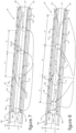
- the chamber 9 houses a distribution device 18 extending in a longitudinal direction D2 parallel to the longitudinal direction D1 of extension of the collector box 7.
- the distribution device 18 comprises a conduit 14 extending along a longitudinal axis A1 between a first end 15 and a second end 16 of the conduit 14.
- the conduit 14 is in particular intended to provide homogenization of the refrigerant fluid FR between its liquid phase and its gas phase during its evacuation from the conduit 14.
- the longitudinal axis A1 of the conduit 14 is oriented parallel to the direction D1 of extension of the collector box 7 and defines the longitudinal direction D2 of extension of the distribution device 18.
- the distribution device 18 is potentially centered inside of the collector box 7 as illustrated on the figure 1 or to be eccentric inside the collector box 7 relative to a median longitudinal axis A2 of extension of the collector box 7 as illustrated in the figure 2 .
- a first longitudinal end 15 of the conduit 14 comprises the inlet mouth 10 for supplying refrigerant fluid FR to the distribution device 18 via the conduit 14.
- the inlet mouth 10 is capable of receiving the refrigerant fluid FR from the exterior of the distribution device 18 either directly or via a junction member of the heat exchanger 5 with the fluidic circuit 1 illustrated in the figure 1 .
- the second end 16 of the conduit 14 is closed.
- At least one orifice 17 is provided through the conduit 14 for the evacuation of the refrigerant fluid FR from the conduit 14 towards the chamber 9.
- the conduit preferably comprises a plurality of orifices 17 provided over at least part of its length for promote the homogenization of the refrigerant fluid evacuated along the conduit 14 between its liquid phase and its gas phase.
- FIG. 3 to 12 various embodiments of a dispensing device 18 according to the invention are illustrated.
- the distribution devices 18 illustrated on the figures 3 to 12 are configured to equip a heat exchanger according to the invention, as illustrated for example on the figures 13 and 14 .
- the distribution devices 18 illustrated on the figures 3 to 12 are arranged to be housed in the collector box 7 from which the tubes 12 of the first layer 12a of tubes 12 of the bundle 6 which the heat exchanger 5 comprises are supplied with refrigerant fluid FR.
- the distribution devices 18 comprise the conduit 14, hereinafter designated first conduit 14, which is provided with the inlet mouth 10 and a plurality of orifices 17 through which the refrigerant fluid FR is evacuated out of the first conduit 14.
- the distribution devices 18 also comprise a second conduit 19 which houses the first conduit 14 and which comprises passages 20 through which the refrigerant fluid FR intended to be admitted inside the distribution devices 18 is sprayed towards the tubes 12 of bundle 6.
- the second conduit 19 surrounds the first conduit 14 at a distance from one another in a direction transverse DT to the longitudinal axis A1 of the first conduit 14.
- the distribution devices 18 comprise a spacing device 21 interposed between the first conduit 14 and the second conduit 19.
- the spacing device 21 thus provides between the first conduit 14 and the second conduit 19 a channel 22 inside which the refrigerant fluid FR is intended to circulate prior to its spraying towards the tubes 12 of bundle 6.
- the second conduit 19 and the first conduit 14 are shown coaxial.
- the orifices 17 are aligned along a first straight line L1 and the passages 20 are aligned along a second straight line L2.
- the first straight line L1 and the second straight line L2 are parallel to the longitudinal axis A1 of the first conduit 14.
- the orifices 17 and the passages 20 are angularly offset over an angular range less than or equal to 180° around the longitudinal axis A1 of the conduit 14.
- the path traveled by the refrigerant fluid FR inside the channel 22 around the conduit 14 , and thus inside the distribution devices 18, is optimized to increase the mixing between a liquid phase and a gas phase of the refrigerant fluid FR sprayed out of the first conduit 14 through the orifices 17.
- the orifices 17 and the passages 20 are angularly offset by 180° around the longitudinal axis A1 of the first conduit 14, following an angle B1 referenced on the Figure 14 .
- the orifices 17 and the passages 20 are angularly offset by an angle B2 less than 180° around the longitudinal axis of the first conduit 14.
- the refrigerant fluid FR is potentially entrained by its gas phase inside the channel 22 around the first conduit 14 over an angular range greater than 180°.
- the number of orifices 17 and the number of passages 20 are different.
- the interposition of the channel 22 between the orifices 17 and the passages 20 makes it possible to dissociate the methods of obtaining a homogeneous mixture between a gas phase and a liquid phase of the refrigerant fluid FR sprayed through the orifices 17, from the distribution methods of the refrigerant fluid FR through the passages 20 out of the distribution devices 18 towards each of the tubes 12 of the bundle 6.
- the refrigerant fluid FR evacuated from the first conduit 14 through the orifices 17 is sprayed inside the channel 22, circulates inside the channel 22 at least partly around the first conduit 14 up to the passages 20 for its evacuation outside distribution devices 18.
- the refrigerant fluid FR is mixed between its liquid phase and its gas phase at the outlet of the first conduit 14 through the orifices 17.
- the circulation of the refrigerant fluid FR inside the channel 22 makes it possible to optimize the mixing of the refrigerant fluid FR between its liquid phase and its gas phase prior to its evacuation from the distribution devices 18 through the passages 20.
- At least one mixer participating in the formation of the spacing device 21 can be advantageously housed inside the channel 22 to further increase the mixing of the refrigerant fluid FR between a liquid phase and a gas phase inside. of channel 22.
- the first conduit 14 and the second conduit 19 have an annular conformation centered on the longitudinal axis A1 of the first conduit 14.
- the transverse section of the conduits 14,19 is of circular conformation.
- the transverse section of the conduits 14,19 is of oblong conformation.
- the spacing device 21 is advantageously used to secure the first conduit 14 and the second conduit 19 to each other, maintaining them firmly in their relative transverse position.
- the spacing device 21 is in particular made from a metallic material, such as aluminum-based, allowing it to be brazed on the first conduit 14 and on the second conduit 14 with which the spacing device 21 is placed in contact .
- the distribution devices 18 can thus be reinforced by the spacing device 21, particularly in the event of a significant extension of a distribution device 18 intended to supply a significant number of tubes 12 of the bundle 6.
- the spacing device 21 comprises various components 21a, 21b, 21c to maintain the first conduit 14 and the second conduit 19 at a distance from each other in the transverse direction DT.
- the components 21a, 21b, 21c of the spacing device 21 can be variously structured and/or be variously positioned inside the distribution devices 18.
- Components 21a, 21b, 21c of the same spacing device 21 can be arranged differently and be used in combinations at least two by two to maintain the first conduit 14 and the second conduit 19 at a determined transverse distance, to the extent where such combinations are compatible with each other.
- components 21a, 21b of the spacer devices 21 are arranged inside the channel 22, being interposed between the wall 14a of the first conduit 14 and the wall 19a of the second conduit 19.
- components 21a, 21b of the spacing devices 21 are arranged at a distance T1 from each other along the distribution devices 18 or in other words along the longitudinal axis A1 of the first conduit 14.
- the components 21a, 21b of the spacing devices 21 can be distributed inside the channel 22 equidistant or at differentiated distances between at least two neighboring components 21a, 21b along the longitudinal axis A1 of the first conduit 14. In d In other words, the distance T1 of distributions of the components 21a, 21b along the longitudinal axis A1 of the first conduit 14 is likely to vary along the distribution devices 18.
- components 21a, 21b of the spacer device 21 each extend partially around the first conduit 14 along a circumference centered on the longitudinal axis A1 of the first conduit 14.
- the partial extension of the components 21a, 21b around of the first conduit 14 is designed to authorize overall occupation of the channel 22 by the refrigerant fluid FR in a continuous volume.
- the components 21a, 21b of the spacing device 21 are then distributed angularly around the first conduit 14, without prejudging their individual distribution positions along the longitudinal axis A1 of the first conduit 14.
- the components 21a, 21b of the spacing device 21 cooperate with each other at least in pairs to maintain the first conduit 14 and the second conduit 19 at a distance from each other in the transverse direction DT.
- components 21a, 21b of the spacing device 21 are arranged in tabs 23 configured as a stop member with a small contact surface with the first conduit 14 and the second conduit 19. At least one set of tabs 23 cooperating with each other provides the relative positioning between the first conduit 14 and the second conduit 19 transversely to the longitudinal axis A1 of the first conduit 14.
- the tabs 23 are for example at least three in number, being distributed at 120° around the longitudinal axis A1 of the first conduit 14.
- the cleats 23 are four in number and are distributed at 90° around the longitudinal axis A1 of the first conduit 14.
- components 21a of the spacer device 21 are arranged in a ring portion 25 or in other words in an open ring.
- the ring portions 25 each extend around the longitudinal axis A1 of the first conduit 14 over an angular range less than 180°, such as for example an angular range of around 120° as illustrated.
- components 21a, 21b of the spacer devices 21 are of closed annular conformation, each extending around the first conduit 14 along the entirety of a circumference centered on the longitudinal axis A1 of the first conduit 14.
- Such components 21a, 21b of the spacing devices 21 are in particular shaped into closed rings 26, which surround the first conduit 14 while being closed on themselves around the first conduit 14.
- the channel 22 is thus compartmentalized along the longitudinal axis A1 of the first conduit into a plurality of cells 22a independent of each other. At least one passage 20 and at least one orifice 17 open into each of the cells 22a.
- the refrigerant fluid FR can thus be admitted inside the channel 22 in a plurality of distinct fractions of refrigerant fluid FR which circulate independently of each other inside the cells 22a.
- the division of the channel 22 into cells 22a independent of each other makes it possible to better control the homogeneity of the quantities of refrigerant fluid FR evacuated from the distribution devices 18 through each of the passages 20.
- the homogeneous supply of the tubes 12 of the bundle 6 in FR refrigerant fluid is reinforced, which makes it possible to increase the performance of the heat exchanger 5.
- the closed rings 26 are defined by a circular transverse profile.
- the closed rings 26 have a transverse profile shaped like an open torus.
- the toroids are preferably flattened at their contact faces with the first conduit 14 and the second conduit 19, to reinforce the extent of contact of the closed rings 26 with the first conduit 14 and the second conduit 19.
- components of the spacer devices 21 are arranged in spacers 21a.
- the spacers 21a are in particular formed by blocks of material attached by brazing to the first conduit 14 and/or to the second conduit 19.
- the spacers 21a can also be formed by depositing molten material on the wall 14a of the first conduit 14 and /or on the wall 19a of the second conduit 19.
- the spacers 21a are formed from rings 25, 26 attached by brazing to the first conduit 14 and/or to the second conduit 19.
- the spacers 21a are formed from pellets 27 attached by brazing or by depositing material on the first conduit 14 and/or on the second conduit 19.
- the pellets 27 are configured as a tab 23, for example being shaped into a spherical cap such that illustrated on the figure 5 or in parallelepipeds more or less elongated along the longitudinal axis A1 of the first conduit 14, as illustrated in the Figure 6 and the figure 13 .
- components of the spacing device 21 are formed by reliefs 21b coming from the wall 14a of the first conduit 14 or from the wall 19a of the second conduit 19.
- the reliefs 21b can be shaped into closed rings 26 as illustrated on the figures 9 And 11 or in cleats 23 as illustrated on the figures 7, 8 , 10 And 12 .
- the reliefs 21b can for example be created by machining or by deformation of the walls 14a, 19a of the conduits referenced 14 and 19.
- the reliefs 21b are formed by deformation of the first conduit 14 and/or the second conduit 19.
- the reliefs 21b are formed by deformation of the second conduit 19.
- the reliefs 21b are formed by deformation of the first conduit 14 or the second conduit 19.
- the deformations of the first conduit 14 and/or the second conduit 19 can be carried out by punching or by stamping, as illustrated in the figures 7, 8 And 10 .
- the reliefs are then, for example, shaped into bosses.
- the deformations of the first conduit 14 and/or the second conduit 19 can also be carried out by pushing back material as illustrated in the figures 9 And 11 .
- the reliefs 21b are then for example shaped into closed rings 26.
- the deformations of the first conduit 14 and/or the second conduit 19 can also be carried out by localized crushing of the first conduit 14 and/or the second conduit 19 transversely on either side of the longitudinal axis A1 of the first conduit 14.
- the reliefs 21b are formed by crushing the first conduit 14, being shaped in particular into bosses.
- the spacing devices 21 comprise at least one component 21c formed of a tip 29a interposed between longitudinal ends 16a, 16b of the first conduit 14 and the second conduit 19 close to each other along the longitudinal axis A1 of the first conduit 14.
- the end piece 29a is of conical conformation to reinforce the rigor of the transverse positioning, in particular coaxial, between the first conduit 14 and the second conduit 19.
- the end piece 29a is for example provided at one of the longitudinal ends 16a of the first conduit 14, and further forms a closing member of this longitudinal end 16a of the first conduit 14.
- the end piece 29a is housed inside a recess 29b of complementary shape provided at the longitudinal end 16b of the second conduit 19, with which the end piece 29a cooperates to maintain the first conduit 14 and the second conduit 19 at a transverse distance relative to the longitudinal axis A1 of the first conduit 14.
- the different examples of realization of the spacing devices 21 illustrated on the figures 3 to 14 are not exhaustive and are not restrictive as to the scope of the invention.
- the different illustrated and described embodiments of the spacing devices 21 present in particular the advantages of being achievable at lower costs and of industrially facilitating the adaptation of the distribution devices 18 according to different heat exchangers 5 of various structures, including in particular tubes 12 of beam 6 to be supplied with FR refrigerant fluid in specific numbers.
- spacing device 21 in accordance with the invention can be implemented to provide relative positioning between the first conduit 14 and the second conduit 19 transversely to the longitudinal axis A1 of the first conduit 14, providing a channel 22 between them.
- heat exchangers 5 are equipped with distribution devices 18 according to the invention.
- the distribution devices 18 are housed inside the collector box 7, the wall 7a of which provides the chamber 9 onto which the tubes 12 of the bundle 6 of the heat exchangers 5 open.
- a space for circulation of the refrigerant fluid FR sprayed out of the distribution device 18 is provided inside the chamber 9.
- the refrigerant fluid FR is capable of circulating inside the chamber 9 at least partly around the second conduit 19 or in other words at least partly around the distribution device 18, prior to its admission to the tubes 12 of the bundle 6.
- the passages 20 are directly communicating with the outlets 24 of the tubes 12 of the bundle 6 on the chamber 9.
- the passages 20 being attached to the outlets 24 of the tubes 12 of the bundle 6.
- the edge of the passages 20 can advantageously be brazed along the edges outlets 24 of the tubes 12 of the bundle 6 on the collector box 7, to provide effective sealing of the joining zone between the passages 20 and the outlets 24 of the tubes 12 of the bundle 6.
- the distribution of the refrigerant fluid FR to each of the tubes 12 of the bundle 6 is thus obtained particularly reliable and efficient, and the homogeneous supply of refrigerant fluid FR to the tubes 12 of the bundle 6 is obtained particularly efficient along the distribution device 18.
- the preceding description clearly explains how the invention makes it possible to achieve the objectives it has set for itself and in particular to propose a distribution device which homogenizes the distribution of the refrigerant fluid along the collector box to guarantee an almost identical refrigerant fluid in each tube of the bundle that comprises the heat exchanger.
- the structural organizations of the distribution device give them adaptability at lower costs according to the arrangement of a specific heat exchanger, in particular with regard to the number of tubes of the bundle which it comprises.
Landscapes
- Engineering & Computer Science (AREA)
- Physics & Mathematics (AREA)
- Thermal Sciences (AREA)
- Mechanical Engineering (AREA)
- General Engineering & Computer Science (AREA)
- Heat-Exchange Devices With Radiators And Conduit Assemblies (AREA)
Claims (15)
- Vorrichtung zur Verteilung (18) eines Kältemittels (FR), die dazu ausgebildet ist, im Inneren eines Sammelkastens (7) eines Wärmetauschers (5) aufgenommen zu sein, wobei die Verteilungsvorrichtung (18) wenigstens eine Leitung (14) aufweist, die sich entlang einer Längsachse (A1) erstreckt, wobei die Leitung (14) an einem ihrer Längsenden (15) eine Einmündung (10) zum Einlass des Kältemittels (FR) in die Leitung (14) aufweist und wenigstens eine Öffnung (17) zur Ableitung des Kältemittels (FR) aus der Leitung (14) aufweist, wobei die Verteilungsvorrichtung (18) die Leitung (14), die mit der Einmündung (10) und der Öffnung (17) versehen ist, erste Leitung (14) genannt, und wenigstens eine zweite Leitung (19) umfasst, die die erste Leitung (14) umgibt und die wenigstens einen Durchlass (20) zur Ableitung des Kältemittels (FR) aus der Verteilungsvorrichtung (18) aufweist, wobei wenigstens ein Abstandshalter (21) zwischen der ersten Leitung (14) und der zweiten Leitung (19) wenigstens einen Verbindungskanal (22) zwischen wenigstens einer Öffnung (17) und wenigstens einem Durchlass (20) bildet, wobei der Abstandshalter (21) wenigstens eine Komponente (21a, 21b, 21c) umfasst, die zwischen der ersten Leitung (14) und der zweiten Leitung (19) angeordnet ist, in der wenigstens eine Komponente (21b) des Abstandshalters (21) von einem Relief (21b) gebildet ist, das aus einer Materialverformung der Wand (19a) der zweiten Leitung (19) zur ersten Leitung (14) entstanden ist, dadurch gekennzeichnet, dass wenigstens eine Komponente (21c) des Abstandshalters (21) von wenigstens einem Endstück (29a) gebildet ist, mit dem wenigstens eins der Längsenden (16a, 16b) einer beliebigen der ersten Leitung (14) und/oder der zweiten Leitung (19) ausgestattet ist, wobei das Endstück (29a) in einer Ausnehmung (29b) mit komplementärer Form aufgenommen ist, die wenigstens eins der Längsenden (16a, 16b) der anderen beliebigen der ersten Leitung (14) und/oder der zweiten Leitung (19) aufweist.
- Verteilungsvorrichtung (18) nach dem vorhergehenden Anspruch, wobei der Abstandshalter (21) mit der ersten Leitung (14) und der zweiten Leitung (19) in Kontakt steht.
- Verteilungsvorrichtung (18) nach einem der vorhergehenden Ansprüche, wobei der Abstandshalter (21) ein Organ zur festen Verbindung der ersten Leitung (14) in der zweiten Leitung (19) bildet.
- Verteilungsvorrichtung (18) nach einem der vorhergehenden Ansprüche, wobei der Abstandshalter (21) ein Organ zur Verstärkung der Verteilungsvorrichtung (18) bildet.
- Verteilungsvorrichtung (18) nach einem der vorhergehenden Ansprüche, wobei der Abstandshalter (21) ein Organ zur Zentrierung der ersten Leitung (14) in der zweiten Leitung (19) bildet.
- Verteilungsvorrichtung (18) nach Anspruch 1, wobei wenigstens eine Komponente (21a, 21b, 21c) des Abstandshalters (21) in der ersten Leitung (14) und/oder der zweiten Leitung (19) enthalten ist.
- Verteilungsvorrichtung (18) nach Anspruch 6, wobei mehrere Komponenten (21a, 21b, 21c, 23, 25, 26, 27, 29a, 29b) des Abstandshalters (21) verschiedene Strukturen aufweisen.
- Verteilungsvorrichtung (18) nach einem der Ansprüche 1, 6 oder 7, wobei wenigstens eine Komponente (21a, 21b) des Abstandshalters (21) im Inneren des Kanals (22) vorgesehen ist.
- Verteilungsvorrichtung (18) nach einem der Ansprüche 1 oder 6 bis 8, wobei mehrere Komponenten (21a, 21b) des Abstandshalters (21) in einem Abstand (T1) voneinander entlang der Längsachse (A1) des ersten Kanals (14) verteilt sind.
- Verteilungsvorrichtung (18) nach Anspruch 9, wobei wenigstens eine Komponente (21a, 21b, 26) des Abstandshalters (21) eine Trennwand des Kanals (22) bildet, den sie in wenigstens zwei aufeinanderfolgende Zellen (22a) entlang der Längsachse (A1) der ersten Leitung (14) aufteilt, wobei wenigstens eine Öffnung (17) und wenigstens ein Durchlass (20) an jeder der Zellen (22a) mündet.
- Verteilungsvorrichtung (18) nach vorhergehenden Ansprüchen 1 oder 6 bis 10, wobei wenigstens eine Komponente (21c) des Abstandshalters (21) an den einen und/oder an den anderen der Längsenden (16a, 16b) der ersten Leitung (14) und der zweiten Leitung (19), die einander am nächsten liegen, vorgesehen ist.
- Verteilungsvorrichtung (18) nach einem der vorhergehenden Ansprüche, wobei die erste Leitung (14) und die zweite Leitung (19) Querschnitte mit komplementärer Form aufweisen, die zwischen ihnen den Kanal (22) bilden.
- Wärmetauscher (5) umfassend einen Sammelkasten (7), der eine Wand aufweist, die eine Kammer (9) begrenzt, die eine Verteilungsvorrichtung (18) nach einem der Ansprüche 1 bis 12 aufnimmt, wobei die Kammer (9) mit einer Mehrzahl von Rohren (12) eines Bündels (6) von Rohren (12) des Wärmetauschers (5) in Verbindung steht.
- Wärmetauscher (5) nach dem vorhergehenden Anspruch, wobei die Verteilungsvorrichtung (18) mit der Wand (7a) des Sammelkastens (7) über die erste Leitung (14), die zweite Leitung (19) und/oder den Abstandshalter (21) in Kontakt steht.
- Wärmetauscher (5) nach einem der Ansprüche 13 und 14, wobei jeder Durchlass (20) außerhalb der ersten Kammer zu einem einzelnen Rohr (12) des Bündels (6) von Rohren (12) mündet.
Applications Claiming Priority (2)
| Application Number | Priority Date | Filing Date | Title |
|---|---|---|---|
| FR1661741A FR3061951B1 (fr) | 2016-11-30 | 2016-11-30 | Dispositif de distribution d'un fluide refrigerant a l'interieur d'une boite collectrice d'un echangeur thermique. |
| PCT/FR2017/053302 WO2018100300A1 (fr) | 2016-11-30 | 2017-11-30 | Dispositif de distribution d'un fluide réfrigérant à l'intérieur d'une boîte collectrice d'un échangeur thermique |
Publications (2)
| Publication Number | Publication Date |
|---|---|
| EP3548825A1 EP3548825A1 (de) | 2019-10-09 |
| EP3548825B1 true EP3548825B1 (de) | 2023-12-13 |
Family
ID=58401700
Family Applications (1)
| Application Number | Title | Priority Date | Filing Date |
|---|---|---|---|
| EP17817790.3A Active EP3548825B1 (de) | 2016-11-30 | 2017-11-30 | Vorrichtung zur verteilung eines kältemittels in einem sammelkasten eines wärmeaustauschers |
Country Status (4)
| Country | Link |
|---|---|
| EP (1) | EP3548825B1 (de) |
| CN (1) | CN110234951B (de) |
| FR (1) | FR3061951B1 (de) |
| WO (1) | WO2018100300A1 (de) |
Families Citing this family (2)
| Publication number | Priority date | Publication date | Assignee | Title |
|---|---|---|---|---|
| EP3855059B1 (de) * | 2020-01-24 | 2023-11-15 | Aptiv Technologies Limited | Passiver strömungsteiler und flüssigkeitskühlsystem damit |
| CN114688765A (zh) * | 2020-12-30 | 2022-07-01 | 广东美的白色家电技术创新中心有限公司 | 换热器和空调器 |
Family Cites Families (9)
| Publication number | Priority date | Publication date | Assignee | Title |
|---|---|---|---|---|
| CA2160274C (en) * | 1995-10-11 | 2000-05-30 | Stanley H. Sather | Heat exchanger for a pulp dryer |
| SE531267C2 (sv) * | 2004-10-21 | 2009-02-03 | Alfa Laval Corp Ab | Plattvärmeväxlare och plattmodul |
| DE202008004582U1 (de) * | 2007-04-16 | 2008-06-19 | Viessmann Werke Gmbh & Co Kg | Plattenwärmetauscher |
| US20110290465A1 (en) | 2010-06-01 | 2011-12-01 | Delphi Technologies, Inc. | Orientation insensitive refrigerant distributor tube |
| KR101372096B1 (ko) * | 2011-11-18 | 2014-03-07 | 엘지전자 주식회사 | 열교환기 |
| DE102011088635A1 (de) * | 2011-12-14 | 2013-06-20 | Behr Gmbh & Co. Kg | Wärmeübertrager |
| US9581397B2 (en) * | 2011-12-29 | 2017-02-28 | Mahle International Gmbh | Heat exchanger assembly having a distributor tube retainer tab |
| KR20140116626A (ko) * | 2013-03-25 | 2014-10-06 | 엘지전자 주식회사 | 열교환기 |
| CN103604254B (zh) * | 2013-11-12 | 2016-07-06 | 清华大学 | 一种内置气液两相流分流结构 |
-
2016
- 2016-11-30 FR FR1661741A patent/FR3061951B1/fr active Active
-
2017
- 2017-11-30 EP EP17817790.3A patent/EP3548825B1/de active Active
- 2017-11-30 CN CN201780084082.4A patent/CN110234951B/zh active Active
- 2017-11-30 WO PCT/FR2017/053302 patent/WO2018100300A1/fr unknown
Also Published As
| Publication number | Publication date |
|---|---|
| CN110234951B (zh) | 2021-08-03 |
| FR3061951B1 (fr) | 2019-06-21 |
| EP3548825A1 (de) | 2019-10-09 |
| FR3061951A1 (fr) | 2018-07-20 |
| CN110234951A (zh) | 2019-09-13 |
| WO2018100300A1 (fr) | 2018-06-07 |
Similar Documents
| Publication | Publication Date | Title |
|---|---|---|
| EP3423770B1 (de) | Vorratsbehälter für phasenwechselmaterial mit einem füllrohr zum befüllen desselben für einen wärmetauscher einer kraftfahrzeug-klimaanlage | |
| EP3548825B1 (de) | Vorrichtung zur verteilung eines kältemittels in einem sammelkasten eines wärmeaustauschers | |
| EP3574506B1 (de) | Kernreaktor mit primärsicherheitswärmetauscher | |
| FR3075346A1 (fr) | Boite collectrice d'un echangeur thermique munie d'un organe de maintien et/ou de positionnement angulaire d'un dispositif de distribution d'un fluide refrigerant | |
| FR3061280B1 (fr) | Dispositif de distribution d'un fluide refrigerant a l'interieur d'une boite collectrice d'un echangeur thermique pour une installation de conditionnement d'air d'un vehicule | |
| EP3548827B1 (de) | Vorrichtung zur verteilung eines kühlmittels in einem sammelkasten eines wärmeaustauschers für eine klimaanlage eines fahrzeugs | |
| FR3059405B1 (fr) | Dispositif de distribution d'un fluide refrigerant a l'interieur d'une boite collectrice d'un echangeur thermique | |
| WO2018100304A1 (fr) | Dispositif de distribution d'un fluide réfrigérant à l'intérieur d'une boîte collectrice d'un échangeur thermique | |
| FR3075349A1 (fr) | Dispositif de distribution d'un fluide refrigerant a l'interieur d'une boite collectrice d'un echangeur thermique, et boite collectrice equipee d'un tel dispositif de distribution | |
| EP3548823B1 (de) | Sammelrohr zur aufnahme eines kältemittels mit mindestens einer vorrichtung zur winkelpositionierung eines rohres | |
| EP3548826B1 (de) | Vorrichtung zum mischen einer kühlflüssigkeit in einem sammelkasten eines wärmeaustauschers | |
| FR3045802A1 (fr) | Echangeur thermique, notamment pour vehicule automobile | |
| EP3394545B1 (de) | Wärmetauscher, insbesondere für ein kraftfahrzeug | |
| FR3061950A1 (fr) | Dispositif d’homogeneisation de la distribution d’un fluide refrigerant a l’interieur de tubes d’un echangeur de chaleur constitutif d’un circuit de fluide refrigerant | |
| EP3394544B1 (de) | Wärmeaustauscher, insbesondere für ein kraftfahrzeug | |
| FR3089612A1 (fr) | Boîte collectrice pour echangeur de chaleur et echangeur de chaleur comprenant une telle boîte collectrice | |
| FR3075345A1 (fr) | Boite collectrice d'un echangeur thermique logeant un dispositif de distribution d'un fluide refrigerant maintenu via un organe de centrage. | |
| FR3059398A1 (fr) | Dispositif de distribution d'un fluide refrigerant a l'interieur d'une boite collectrice d'un echangeur thermique pour une installation de conditionnement d'air d'un vehicule | |
| WO2018100312A1 (fr) | Boîte collectrice d'un échangeur thermique pour module d'admission d'un moteur à combustion interne | |
| FR3075347A1 (fr) | Dispositif de distribution d'un fluide refrigerant destine a etre loge dans une boite collectrice d'un echangeur de chaleur | |
| WO2017109350A1 (fr) | Échangeur thermique, notamment pour vehicule automobile | |
| FR3075348A1 (fr) | Dispositif de distribution d'un fluide refrigerant destine a etre loge dans une boite collectrice d'un echangeur de chaleur | |
| WO2017109348A1 (fr) | Échangeur thermique, notamment pour véhicule automobile | |
| FR3059406A1 (fr) | Dispositif de mixage d'un fluide refrigerant a l'interieur d'une boite collectrice d'un echangeur thermique pour une installation de conditionnement d'air d'un vehicule | |
| FR3045805A1 (fr) | Echangeur thermique, notamment pour vehicule automobile |
Legal Events
| Date | Code | Title | Description |
|---|---|---|---|
| STAA | Information on the status of an ep patent application or granted ep patent |
Free format text: STATUS: UNKNOWN |
|
| STAA | Information on the status of an ep patent application or granted ep patent |
Free format text: STATUS: THE INTERNATIONAL PUBLICATION HAS BEEN MADE |
|
| PUAI | Public reference made under article 153(3) epc to a published international application that has entered the european phase |
Free format text: ORIGINAL CODE: 0009012 |
|
| STAA | Information on the status of an ep patent application or granted ep patent |
Free format text: STATUS: REQUEST FOR EXAMINATION WAS MADE |
|
| 17P | Request for examination filed |
Effective date: 20190614 |
|
| AK | Designated contracting states |
Kind code of ref document: A1 Designated state(s): AL AT BE BG CH CY CZ DE DK EE ES FI FR GB GR HR HU IE IS IT LI LT LU LV MC MK MT NL NO PL PT RO RS SE SI SK SM TR |
|
| AX | Request for extension of the european patent |
Extension state: BA ME |
|
| DAV | Request for validation of the european patent (deleted) | ||
| DAX | Request for extension of the european patent (deleted) | ||
| STAA | Information on the status of an ep patent application or granted ep patent |
Free format text: STATUS: EXAMINATION IS IN PROGRESS |
|
| STAA | Information on the status of an ep patent application or granted ep patent |
Free format text: STATUS: EXAMINATION IS IN PROGRESS |
|
| 17Q | First examination report despatched |
Effective date: 20201026 |
|
| STAA | Information on the status of an ep patent application or granted ep patent |
Free format text: STATUS: EXAMINATION IS IN PROGRESS |
|
| GRAP | Despatch of communication of intention to grant a patent |
Free format text: ORIGINAL CODE: EPIDOSNIGR1 |
|
| STAA | Information on the status of an ep patent application or granted ep patent |
Free format text: STATUS: GRANT OF PATENT IS INTENDED |
|
| INTG | Intention to grant announced |
Effective date: 20230424 |
|
| GRAJ | Information related to disapproval of communication of intention to grant by the applicant or resumption of examination proceedings by the epo deleted |
Free format text: ORIGINAL CODE: EPIDOSDIGR1 |
|
| STAA | Information on the status of an ep patent application or granted ep patent |
Free format text: STATUS: EXAMINATION IS IN PROGRESS |
|
| P01 | Opt-out of the competence of the unified patent court (upc) registered |
Effective date: 20230528 |
|
| GRAP | Despatch of communication of intention to grant a patent |
Free format text: ORIGINAL CODE: EPIDOSNIGR1 |
|
| STAA | Information on the status of an ep patent application or granted ep patent |
Free format text: STATUS: GRANT OF PATENT IS INTENDED |
|
| INTC | Intention to grant announced (deleted) | ||
| INTG | Intention to grant announced |
Effective date: 20230718 |
|
| GRAS | Grant fee paid |
Free format text: ORIGINAL CODE: EPIDOSNIGR3 |
|
| GRAA | (expected) grant |
Free format text: ORIGINAL CODE: 0009210 |
|
| STAA | Information on the status of an ep patent application or granted ep patent |
Free format text: STATUS: THE PATENT HAS BEEN GRANTED |
|
| AK | Designated contracting states |
Kind code of ref document: B1 Designated state(s): AL AT BE BG CH CY CZ DE DK EE ES FI FR GB GR HR HU IE IS IT LI LT LU LV MC MK MT NL NO PL PT RO RS SE SI SK SM TR |
|
| REG | Reference to a national code |
Ref country code: GB Ref legal event code: FG4D Free format text: NOT ENGLISH |
|
| REG | Reference to a national code |
Ref country code: CH Ref legal event code: EP |
|
| REG | Reference to a national code |
Ref country code: DE Ref legal event code: R096 Ref document number: 602017077517 Country of ref document: DE |
|
| REG | Reference to a national code |
Ref country code: IE Ref legal event code: FG4D Free format text: LANGUAGE OF EP DOCUMENT: FRENCH |
|
| PG25 | Lapsed in a contracting state [announced via postgrant information from national office to epo] |
Ref country code: GR Free format text: LAPSE BECAUSE OF FAILURE TO SUBMIT A TRANSLATION OF THE DESCRIPTION OR TO PAY THE FEE WITHIN THE PRESCRIBED TIME-LIMIT Effective date: 20240314 |
|
| REG | Reference to a national code |
Ref country code: LT Ref legal event code: MG9D |
|
| PG25 | Lapsed in a contracting state [announced via postgrant information from national office to epo] |
Ref country code: LT Free format text: LAPSE BECAUSE OF FAILURE TO SUBMIT A TRANSLATION OF THE DESCRIPTION OR TO PAY THE FEE WITHIN THE PRESCRIBED TIME-LIMIT Effective date: 20231213 |
|
| REG | Reference to a national code |
Ref country code: NL Ref legal event code: MP Effective date: 20231213 |
|
| PG25 | Lapsed in a contracting state [announced via postgrant information from national office to epo] |
Ref country code: ES Free format text: LAPSE BECAUSE OF FAILURE TO SUBMIT A TRANSLATION OF THE DESCRIPTION OR TO PAY THE FEE WITHIN THE PRESCRIBED TIME-LIMIT Effective date: 20231213 |
|
| PG25 | Lapsed in a contracting state [announced via postgrant information from national office to epo] |
Ref country code: LT Free format text: LAPSE BECAUSE OF FAILURE TO SUBMIT A TRANSLATION OF THE DESCRIPTION OR TO PAY THE FEE WITHIN THE PRESCRIBED TIME-LIMIT Effective date: 20231213 Ref country code: GR Free format text: LAPSE BECAUSE OF FAILURE TO SUBMIT A TRANSLATION OF THE DESCRIPTION OR TO PAY THE FEE WITHIN THE PRESCRIBED TIME-LIMIT Effective date: 20240314 Ref country code: ES Free format text: LAPSE BECAUSE OF FAILURE TO SUBMIT A TRANSLATION OF THE DESCRIPTION OR TO PAY THE FEE WITHIN THE PRESCRIBED TIME-LIMIT Effective date: 20231213 Ref country code: BG Free format text: LAPSE BECAUSE OF FAILURE TO SUBMIT A TRANSLATION OF THE DESCRIPTION OR TO PAY THE FEE WITHIN THE PRESCRIBED TIME-LIMIT Effective date: 20240313 |