EP3548826B1 - Vorrichtung zum mischen einer kühlflüssigkeit in einem sammelkasten eines wärmeaustauschers - Google Patents
Vorrichtung zum mischen einer kühlflüssigkeit in einem sammelkasten eines wärmeaustauschers Download PDFInfo
- Publication number
- EP3548826B1 EP3548826B1 EP17817791.1A EP17817791A EP3548826B1 EP 3548826 B1 EP3548826 B1 EP 3548826B1 EP 17817791 A EP17817791 A EP 17817791A EP 3548826 B1 EP3548826 B1 EP 3548826B1
- Authority
- EP
- European Patent Office
- Prior art keywords
- mixing
- pipe
- duct
- mixing device
- refrigerant fluid
- Prior art date
- Legal status (The legal status is an assumption and is not a legal conclusion. Google has not performed a legal analysis and makes no representation as to the accuracy of the status listed.)
- Active
Links
Images




Classifications
-
- F—MECHANICAL ENGINEERING; LIGHTING; HEATING; WEAPONS; BLASTING
- F28—HEAT EXCHANGE IN GENERAL
- F28F—DETAILS OF HEAT-EXCHANGE AND HEAT-TRANSFER APPARATUS, OF GENERAL APPLICATION
- F28F9/00—Casings; Header boxes; Auxiliary supports for elements; Auxiliary members within casings
- F28F9/02—Header boxes; End plates
- F28F9/026—Header boxes; End plates with static flow control means, e.g. with means for uniformly distributing heat exchange media into conduits
- F28F9/027—Header boxes; End plates with static flow control means, e.g. with means for uniformly distributing heat exchange media into conduits in the form of distribution pipes
- F28F9/0273—Header boxes; End plates with static flow control means, e.g. with means for uniformly distributing heat exchange media into conduits in the form of distribution pipes with multiple holes
-
- F—MECHANICAL ENGINEERING; LIGHTING; HEATING; WEAPONS; BLASTING
- F25—REFRIGERATION OR COOLING; COMBINED HEATING AND REFRIGERATION SYSTEMS; HEAT PUMP SYSTEMS; MANUFACTURE OR STORAGE OF ICE; LIQUEFACTION SOLIDIFICATION OF GASES
- F25B—REFRIGERATION MACHINES, PLANTS OR SYSTEMS; COMBINED HEATING AND REFRIGERATION SYSTEMS; HEAT PUMP SYSTEMS
- F25B39/00—Evaporators; Condensers
- F25B39/02—Evaporators
- F25B39/028—Evaporators having distributing means
-
- F—MECHANICAL ENGINEERING; LIGHTING; HEATING; WEAPONS; BLASTING
- F28—HEAT EXCHANGE IN GENERAL
- F28F—DETAILS OF HEAT-EXCHANGE AND HEAT-TRANSFER APPARATUS, OF GENERAL APPLICATION
- F28F13/00—Arrangements for modifying heat-transfer, e.g. increasing, decreasing
- F28F13/06—Arrangements for modifying heat-transfer, e.g. increasing, decreasing by affecting the pattern of flow of the heat-exchange media
- F28F13/12—Arrangements for modifying heat-transfer, e.g. increasing, decreasing by affecting the pattern of flow of the heat-exchange media by creating turbulence, e.g. by stirring, by increasing the force of circulation
-
- F—MECHANICAL ENGINEERING; LIGHTING; HEATING; WEAPONS; BLASTING
- F28—HEAT EXCHANGE IN GENERAL
- F28F—DETAILS OF HEAT-EXCHANGE AND HEAT-TRANSFER APPARATUS, OF GENERAL APPLICATION
- F28F9/00—Casings; Header boxes; Auxiliary supports for elements; Auxiliary members within casings
- F28F9/02—Header boxes; End plates
- F28F9/026—Header boxes; End plates with static flow control means, e.g. with means for uniformly distributing heat exchange media into conduits
- F28F9/028—Header boxes; End plates with static flow control means, e.g. with means for uniformly distributing heat exchange media into conduits by using inserts for modifying the pattern of flow inside the header box, e.g. by using flow restrictors or permeable bodies or blocks with channels
Definitions
- the field of the present invention is that of heat exchangers fitted to air conditioning installations for a vehicle, in particular an automobile.
- the invention relates more specifically to the methods of distributing a refrigerant fluid inside a header box that includes such a heat exchanger.
- a vehicle is commonly equipped with an air conditioning installation for thermally treating the air present or sent into the passenger compartment of the vehicle.
- an air conditioning installation for thermally treating the air present or sent into the passenger compartment of the vehicle.
- Such an installation comprises a closed circuit inside which a refrigerant fluid circulates. Successively depending on the direction of circulation of the refrigerant through it, the circuit essentially comprises a compressor, a condenser, an expansion valve and at least one heat exchanger.
- the heat exchanger commonly comprises a bundle of tubes interposed between a header box and a coolant fluid return box.
- the refrigerant fluid is admitted through an inlet mouth inside a collector box, circulates along successive paths in the tubes of the bundle between the collector box and a return box, then is evacuated out of the exchanger heat through an outlet.
- the outlet mouth is likely to be formed through the collector box or through the return box.
- the heat exchanger is for example an evaporator providing a heat exchange between the refrigerant fluid and an air flow passing through it.
- the refrigerant fluid circulates inside the tubes of the bundle and the air flow circulates along the tubes of the bundle for its cooling.
- a problem posed lies in the fact that the refrigerant fluid is in the two-phase liquid/gaseous state when it is admitted inside the heat exchanger. Due to the difference in physical properties between liquid and gas, the refrigerant tends to separate into its liquid phase and its gas phase.
- the tubes of the bundle located closest to the inlet mouth are mainly supplied with liquid and conversely the tubes of the bundle furthest from the inlet mouth are mainly supplied with gas.
- This phenomenon generates heterogeneity in the temperature of the air flow which has passed through the heat exchanger in operation. This heterogeneity complicates the thermal management of the device which receives the heat exchanger and ultimately involves temperature differences between two areas of the passenger compartment, while the same air flow temperature is required.
- the subject of the present invention is a device for mixing a refrigerant fluid configured to be housed inside a header box of a heat exchanger into which tubes of a bundle of tubes comprising the heat exchanger open.
- the mixing device is in particular intended to mix a gaseous phase with a liquid phase of the refrigerant fluid distributed by the mixing device inside the header box.
- a mixing device according to the preamble of claim 1 is known from JP2002-22313 .
- the invention also relates to a heat exchanger comprising a header box housing a mixing device according to the invention.
- the heat exchanger is in particular arranged to equip an air conditioning installation of a vehicle, in particular an automobile.
- An object of the invention is to perfect the uniformity of the temperature of the heat exchanger in operation and finally to improve its efficiency. It is more specifically aimed by the invention to perfect a distribution in the header box of the coolant in a homogeneous manner between its liquid phase and its gaseous phase.
- a header box housing a mixing device capable of supplying refrigerant fluid to the tubes of the heat exchanger bundle, by providing efficient homogenization of the refrigerant fluid between its liquid phase and its gaseous phase, and a distribution homogeneous coolant fluid inside each of the tubes of the bundle.
- Another object of the invention is to propose a mixing device which can be obtained industrially at lower cost.
- Another object of the invention is to provide a mixing device whose organization allows it to be easily and inexpensively adapted to heat exchangers of various structures.
- Such a diversity of structures of the heat exchangers is in particular to be assessed with regard to the number of tubes of the bundle that they comprise, the methods of circulation of the refrigerant fluid inside the heat exchanger and/or the relative positions between the mouth inlet and the outlet mouth of the coolant contained in the heat exchanger.
- the mixing device of the invention comprises a conduit with a longitudinal axis provided with an inlet mouth for the admission of the refrigerant fluid into the conduit and with at least one orifice for the spraying of the refrigerant fluid out of the conduit.
- the duct comprises at least one mixing member arranged on an internal face of the duct and capable of modifying the flow of the refrigerant fluid circulating inside the duct.
- the internal face of the conduit is configured as a mixing means comprising at least one mixing member capable of mixing the refrigerant fluid between a liquid phase and a gaseous face inside the conduit.
- the mixing member disturbs a laminar flow of the refrigerant fluid circulating inside the duct from the inlet mouth towards the orifice or orifices.
- the internal face of the duct comprises at least one mixing member which modifies the regularity of the extension of the internal face of the duct along a guideline, or more specifically along a generatrix, which is parallel to the longitudinal axis of the leads.
- the mixing member thus provides a relief on the internal face of the duct which projects towards the inside of the duct with respect to a direction of extension of the internal face of the duct parallel to its longitudinal axis.
- the extension of the projection of the relief towards the interior of the duct is liable to vary between two mixing members.
- the mixing member generates disturbances in the flow of the refrigerant fluid inside the conduit, which promotes its mixing between a liquid phase and a gaseous phase inside the conduit.
- a mixture of the refrigerant fluid between a liquid phase and a gaseous phase is thus produced inside the conduit prior to its evacuation through the orifice or orifices.
- the coolant sprayed at the level of each of the orifices is thus formed of a more homogeneous liquid/gas mixture, and this for each of the orifices distributed over the length of the pipe.
- the modalities providing a mixture of the refrigerant fluid between its liquid phase and its gaseous phase inside the conduit are thus advantageously dissociated from the modalities of spraying the refrigerant fluid out of the conduit further causing a mixture of the refrigerant fluid between its liquid phase and its phase. gas at the outlet of the mixing device.
- the refrigerant fluid is thus mixed between its liquid phase and its gaseous phase by means of the mixing device in successive stages.
- a first mixing step is carried out inside the conduit by one or more mixing members and a second mixing step is carried out during the spraying of the refrigerant fluid out of the conduit through the orifice(s).
- a heat exchanger equipped with a collector box housing the mixing device is thus obtained with particularly high performance, in particular by presenting a substantially balanced temperature over the whole of its heat exchange surface formed by the tubes of a bundle of tubes which it includes.
- the mixing member extends inside the duct at least transversely to its longitudinal axis and partially inside the recess of the duct delimited by its wall, forming an obstacle opposing a laminar flow of the refrigerant fluid inside the duct.
- the transverse extension of the mixing member with respect to the duct is capable of being perpendicular or inclined with respect to the longitudinal axis of the duct.
- the obstacle formed by the mixing member is in particular configured in a relief extending partially towards the inside of the duct.
- the central zone of the duct is unoccupied by the relief and provides a passage for the refrigerant inside and along the duct.
- the obstacle is capable of disturbing a laminar flow of the refrigerant fluid inside the duct and of forcing its passage through the orifice or orifices located downstream of the mixing member.
- the upstream and downstream concepts are relative concepts considered with regard to the intended direction of circulation of the refrigerant fluid inside the duct or in other words with regard to a path of circulation of the refrigerant fluid arranged inside the duct. from the inlet mouth to the orifice.
- the mixing member is incorporated into the wall of the duct.
- the mixing device can thus be obtained at moderate costs by incorporating the mixing member into the inner face of the duct.
- the mixing device is easily adaptable for conduits having different dimensions of extension along their longitudinal axis depending on the configuration of the heat exchanger, in particular with regard to the number of tubes of a bundle to be supplied with refrigerant fluid that the exchanger comprises and which lead to a header box housing the mixing device.
- the incorporation of the mixing member into the wall of the duct can be carried out at lower cost using various techniques.
- the mixing member is incorporated into the wall of the duct by brazing, by molding, by adding material, by deforming the wall of the duct or by machining the wall of the duct.
- the mixing member is incorporated into the wall of the duct by brazing, the mixing member and the duct being at least in this case made of metallic material, in particular based on aluminium.
- the brazing between the mixing device and the wall of the duct is in particular carried out during a brazing operation between them of the components that comprise a heat exchanger and comprising at least one header box housing the mixing device and preferably also tubes a bundle of tubes to be supplied with coolant by the mixing device.
- the brazing between the mixing device and the wall of the duct can also be carried out prior to the installation of the mixing device inside the collector box.
- the mixing device then forms a unitary assembly that can be easily mounted and positioned inside the header box.
- the mixing member is incorporated into the wall of the molding duct or in other words during manufacture by molding of the duct.
- a molding operation can be carried out to form simultaneously in the same body the duct provided with the mixing member.
- the incorporation by molding of the mixing member into the duct can also be carried out in several steps, including a first step of molding the duct and a second step of overmolding the mixing member inside the duct.
- the mixing member is incorporated into the wall of the duct by machining the wall of the duct leaving at least one projecting relief oriented towards the inside of the duct, the relief then forming the mixing. More particularly still according to another embodiment, the mixing member is incorporated into the wall of the duct by deformation of the wall of the duct causing a discharge of material towards the inside of the duct which spares at least the relief then forming the mixing member.
- the incorporation of the mixing member into the duct induces a variation in the thickness of its wall. More particularly, the thickness of the wall of the duct varies in planes perpendicular to the longitudinal axis of the duct and longitudinally distant. The thickness of the wall of the duct is in particular increased by at least one mixing member. The internal section of the duct is reduced by at least one mixing member.
- the mixing member modifies the conformation of the wall of the duct by varying its thickness longitudinally.
- a first thickness of the wall of the conduit measured in a first perpendicular plane crossing a relief formed by the mixing member is greater than a second thickness of the wall of the conduit measured in a second perpendicular plane considered at the longitudinal edge of the relief .
- At least one mixing member extends perpendicular to the longitudinal axis of the duct.
- At least one mixing member is inclined at least in a longitudinal extension plane and relative to the longitudinal axis of the duct, forming a guide ramp for the refrigerant fluid towards the orifice.
- the mixing member is in particular oriented according to the intended direction of circulation of the coolant fluid inside the duct to direct the coolant fluid towards the inner face of the duct delimiting its recess and more particularly towards the orifice or orifices.
- the mixing member may be of planar configuration, in particular being arranged in a ring.
- a ring can be oriented perpendicular to the longitudinal axis of the duct.
- the ring can also be inclined with respect to the longitudinal axis of the duct in a longitudinal extension plane parallel to the longitudinal axis of the duct and/or be oriented along a transverse plane inclined at an angle less than 90° by relative to the longitudinal extension plane.
- the inclination of the mixing member may also involve its extension inside the duct along a curve defined by a combination between a perpendicular direction and a longitudinal direction with respect to the longitudinal axis of the duct, in particular a helical extension.
- at least one mixing member is formed by at least one helical thread formed in the wall of the duct and wound around the longitudinal axis of the duct.
- the orifice(s) can be oriented perpendicular to the longitudinal axis of the duct or be inclined towards one and/or the other of the longitudinal ends of the duct.
- the cross-section of at least one orifice along a plane perpendicular to the longitudinal axis of the duct may for example be of circular, oblong and/or polygonal conformation such as triangular, hexagonal or cross-shaped for example.
- the section of the orifice(s) along a plane perpendicular to the longitudinal axis of the duct has a maximum surface area of between 2 mm 2 and 5 mm 2 .
- the orifices are distributed along the duct along its longitudinal axis.
- the orifices can be distributed by being aligned along several straight lines parallel to the longitudinal axis of the duct.
- the orifices can be staggered along the duct.
- the orifices can be distributed along a line configured as a helix wound around the duct.
- the orifices are distributed along a straight line parallel to the longitudinal axis of the duct.
- the inlet mouth is preferably made at a first longitudinal end of the duct.
- a second longitudinal end of the conduit is closed.
- the second longitudinal end is understood as being the longitudinal end of the duct axially located opposite its first longitudinal end provided with the inlet mouth.
- the inlet mouth is in particular provided by an outlet from the recess of the duct towards the outside of the duct.
- the inlet is in particular connectable to a source of refrigerant fluid directly via the first end of the duct or via a hydraulic member interposed between the duct and the fluid source.
- the source of fluid is in particular formed by a circuit of refrigerant fluid comprising the heat exchanger.
- the second end of the duct is for example closed by a plug, by an end fitting capping the second end of the duct and/or by a cap that can be integrated into the duct, in particular by brazing.
- the plug can also, for example, still be formed by a wall of the header box bearing against an end edge of the duct.
- the characteristics relating to the orifice(s) presented below relate to a plane which extends parallel to the longitudinal axis of the duct and which passes through the duct(s). This plane is referred to below as the longitudinal plane passing through at least one orifice.
- mixing members are distributed along the longitudinal axis of the duct. It is understood here that in this plane, the mixing members are separated from each other by a non-zero longitudinal distance along the longitudinal axis of the duct.
- At least one mixing device is arranged upstream of at least one orifice, in a flow direction of the coolant fluid inside the duct defined from the inlet mouth towards the orifice.
- the obstacle formed by the mixing member disturbs the flow of the refrigerant fluid and promotes its entrainment towards the orifice located downstream of the mixing member.
- At least one mixing member is interposed between at least two orifices distributed along the longitudinal axis of the duct.
- the mixture between a liquid phase and a gaseous phase of the coolant can be obtained homogeneous between the fractions of coolant flowing through each of the orifices.
- the relative positions between the orifices and the mixing devices along the duct are adapted taking into account in particular the speed of the refrigerant fluid inside the duct and/or the variation in the state of the mixture of the refrigerant flowing along the pipe.
- the mixing devices are arranged at a first separation distance between two adjacent mixing devices which is equal to a second separation distance between two adjacent orifices.
- at least one orifice is equidistant from two mixing members.
- the mixing devices are arranged at a first separation distance between two adjacent mixing devices which is greater than a second separation distance between two adjacent orifices.
- At least one mixing member is interposed between two groups of orifices each comprising as an indication a number of orifices comprised between one and four.
- the mixing member is shaped like a ring, the opening of which provides through it a passage for the refrigerant fluid.
- the periphery of the ring marries in particular the internal face of the wall of the duct or in other words is in contact with the internal face of the duct along its circumference.
- the ring is preferably centered on the longitudinal axis of the duct.
- Such a ring can advantageously be secured by brazing to the conduit or, for example, be formed by deformation of the wall of the conduit causing a discharge of material constituting the ring.
- the dimension of the opening of the ring is between 10% and 70% of the largest dimension of the recess of the duct measured in a plane perpendicular to the longitudinal axis of the duct.
- the openings of at least two successive rings along the longitudinal axis of the duct have identical sections in the plane of the rings.
- the openings of at least two successive rings along the longitudinal axis of the duct have different sections in the plane of the rings.
- the sections of the openings of the rings vary according to their position along the longitudinal axis of the duct.
- the variations of the sections of the openings of the rings can be regular or irregular, in particular depending on the successive positions of the rings, along the longitudinal axis of the duct.
- the openings of the rings are progressively narrowed along the longitudinal axis of the duct from the first longitudinal end towards the second longitudinal end of the duct or in other words according to the direction of circulation of the refrigerant fluid from the entrance mouth to the orifices.
- At least one mixing member is shaped as at least one helix portion wound around the longitudinal axis of the duct. It will be noted that at least one mixing member is capable of being shaped like a ring and at least one mixing member is capable of being shaped like at least one portion of a helix.
- mixing members are shaped as helices of the same pitch angularly distributed around the longitudinal axis of the duct. More particularly, each of the helices is wound around the longitudinal axis of the duct, extending along the duct in its part comprising the orifice or orifices.
- At least one orifice passes through at least one mixing member.
- the duct includes mixing members shaped as helices, at least one orifice being able to pass through the projecting relief formed by a helix and at least one orifice being able to pass through the wall of the duct between two helices.
- the duct comprises mixing members shaped as rings, at least one orifice which can pass through a ring and at least one orifice which can pass through the wall of the duct between two rings.
- At least one orifice is capable of extending through the wall of the duct by crossing a mixing member and at least one orifice is capable of extending through the wall of the duct in a zone of the duct devoid of a mixing member .
- the mixing of the refrigerant fluid between a gaseous phase and a liquid phase can thus be controlled by varying the length of the orifices, along the duct.
- the mixture of the refrigerant fluid evacuated through each of the orifices can be adjusted to provide a distribution of the refrigerant fluid outside the mixing device which is globally homogeneous along the longitudinal axis of the leads.
- the mixing of the refrigerant fluid between its gaseous phase and its liquid phase inside the duct can be controlled according to the relative positions of the orifices with respect to the mixing members. It can in particular be taken into account a proximity between the obstacles formed by the mixing members and the outlet of at least a part of the orifices inside the duct, and/or the crossing character or not of at least one member. mixing by at least one orifice.
- the invention also relates to a heat exchanger equipped with a mixing device according to the invention.
- a heat exchanger of the invention comprises a header box providing a chamber housing a mixing device according to the invention.
- the heat exchanger also comprises tubes of a bundle of tubes opening into the chamber for their supply with refrigerant fluid by the mixing device.
- the mixing device is in particular incorporated into a wall of the header box by brazing.
- the positioning of the mixing device inside the header box can advantageously be achieved via at least one angular and/or axial positioning device interposed between the mixing device and a wall of the header box.
- One or more such positioning devices are preferably provided at at least one of the longitudinal ends of the conduit along its longitudinal axis. Brazing between the mixing device and a wall of the header box can be performed via at least one such positioning device.
- a space for the circulation of the refrigerant fluid is provided inside the chamber at least partly around the mixing device towards outlets of the tubes of the bundle on the chamber.
- an additional step of mixing the coolant between its liquid phase and its gaseous phase can be carried out inside the chamber prior to its admission inside the tubes of the bundle.
- the orifices and outlets of the tubes of the bundle on the chamber are angularly offset from each other around the longitudinal axis of the duct.
- the circulation path of the coolant fluid inside the collector box can thus be adjusted according to the mixture of the coolant fluid to be obtained inside the chamber.
- Such adjustment is in particular provided via one or more angular and/or axial positioning devices interposed between the mixing device and a wall of the header box.
- the orifices and the outlets of the tubes of the bundle on the chamber are arranged diametrically opposite each other with respect to the longitudinal axis of the duct, to optimize the circulation path of the refrigerant inside the chamber. bedroom.
- outlets of the tubes of the bundle on the chamber are provided through a wall of the header box delimiting the chamber.
- the tubes of the bundle are provided between plates incorporating the header box while being stacked along the longitudinal axis of the duct.
- the plates include eyelets which delimit the chamber and which are extended by extensions of the plates providing the tubes of the bundle between them.
- the eyelets are crossed by the mixing device.
- the mixing device can be placed in contact with the eyelets at at least one of its ends.
- the heat exchanger is more particularly configured to be used as an evaporator.
- the heat exchanger can be used to cool a flow of air passing through it or to cool a liquid dedicated to cooling a component, such as at least one battery of a vehicle supplying the energy necessary at least in part to its propulsion.
- Another subject of the invention is a refrigerant fluid circuit comprising at least one compressor, a condenser, an expansion device and a heat exchanger in accordance with the invention, through which a refrigerant fluid passes.
- the invention also relates to a ventilation, heating and/or air conditioning installation, or air conditioning installation, configured to equip a vehicle.
- the air conditioning installation of the invention comprises at least one heat exchanger in accordance with the invention.
- an air conditioning installation for a vehicle comprises a closed circuit 1 inside which a refrigerant fluid FR circulates.
- circuit 1 essentially comprises, successively in the direction S1 of circulation of the refrigerant fluid FR, a compressor 2, a condenser 3 or gas cooler, an expansion device 4 and at least one heat exchanger 5 .
- circuit 1 The example given of a minimum architecture of circuit 1 is given for information only and is not restrictive as to the scope of the invention with regard to various potential architectures of circuit 1.
- the heat exchanger 5 is for example dedicated to cooling an air flow FA passing through it, as illustrated in the figure 2 .
- Such an air flow FA is used in particular for thermally treating the air in the passenger compartment of the vehicle or, for example, to cool a component of the vehicle in operation.
- the heat exchanger 5 is dedicated to cooling a liquid used to cool a component of the vehicle in operation, such as one or more batteries supplying electrical energy to a propulsion electric motorization of the vehicle.
- the heat exchanger 5 comprises a bundle 6 interposed between a header box 7 and a return box 8.
- the header box 7 extends in a longitudinal direction D1 oriented perpendicular to a direction D3 of extension of the tubes 12 of the bundle 6 between the header box 7 and the return box 8.
- the header box 7 delimits a chamber 9 supplied with refrigerant fluid FR through an inlet 10.
- the refrigerant fluid FR circulates inside the heat exchanger 5 to cool at least the tubes 12 of the bundle 6 and the air FA passing through it, then is evacuated from the heat exchanger 5 through an outlet mouth 11.
- the outlet mouth 11 is provided through the collector box 7, which implies that the heat exchanger 5 is a “U” circulation heat exchanger.
- the outlet mouth 11 can be provided through the return box 8, which then implies that the heat exchanger 5 is an “I” circulation heat exchanger.
- the heat exchanger 5 is of the type with U-shaped circulation of the refrigerant fluid FR.
- the heat exchanger 5 is intended for cooling an air flow FA.
- the tubes 12 of the bundle 6 include fins 13 favoring the heat exchange between the air flow FA and the tubes 12 of the bundle 6.
- the air flow FA crosses the bundle 6 transversely to the general plane P1 of the heat exchanger 5, flowing along the tubes 12.
- the refrigerant fluid FR circulates from the header box 7 to a first layer 12a of tubes 12 of the bundle 6 dedicated to supplying the return box 8 with refrigerant fluid FR. Then the refrigerant fluid FR circulates from the return box 8 to the collector box 7 through a second layer 12b of tubes 12 of the bundle 6. The first layer 12a and the second layer 12b are superimposed according to the direction of circulation of the flow of air FA through the heat exchanger 5.
- Such a configuration of the heat exchanger 5 makes it particularly useful to obtain a homogeneous distribution of the refrigerant fluid FR between its liquid phase and its gaseous phase and a homogeneous distribution of the refrigerant fluid FR along the collector box 7 towards each of the tubes 12 of the first layer 12a of bundle 6.
- the chamber 9 houses a mixing device 18 extending along a longitudinal direction D2 parallel to the longitudinal direction D1 of extension of the header box 7.
- the mixing device 18 comprises a duct 14 extending along a longitudinal axis A1 between a first end 15 and a second end 16 of the mixing device 18.
- the conduit 14 is intended in particular to provide homogenization of the refrigerant fluid FR between its liquid phase and its gaseous phase during its evacuation from the conduit 14.
- the longitudinal axis A1 of the duct 14 is oriented parallel to the direction D1 of extension of the manifold 7 and defines the longitudinal direction D2 of extension of the mixing device 18.
- the mixing device 18 is potentially centered inside of the collector box 7 as shown in the figure 1 .
- the mixing device 18 may be offset inside the collector box 7 with respect to a median longitudinal axis A2 of extension of the collector box 7.
- the mixing device 18 includes an inlet 10 for supplying it with refrigerant fluid FR.
- the inlet 10 is formed at a first longitudinal end of the duct 14.
- the inlet 10 is capable of receiving the refrigerant fluid FR from outside the mixing device 18 either directly or via a junction member of the heat exchanger 5 with the fluidic circuit 1 illustrated in the figure 1 .
- the second end of conduit 14 is closed.
- At least one orifice 17 is provided through the duct 14 for the evacuation of the refrigerant fluid FR from the duct 14 to the chamber 9.
- the duct 14 preferably comprises a plurality of orifices 17 provided over at least a part of its length. to promote the homogenization of the refrigerant FR evacuated along the pipe 14 between its liquid phase and its gaseous phase.
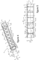
- the mixing device 18 illustrated for example on the figures 3 to 9 is arranged to be housed inside a chamber 9 of a header box 7 that includes a heat exchanger 5, as illustrated for example in the figure 10 .
- the mixing devices 18 comprise the duct 14 provided with orifices 17 which are made through the wall 14a of the duct 14 while being aligned along a straight line L1 oriented parallel to the longitudinal axis A1 of the duct 14.
- the duct 14 has the inlet 10 at its first longitudinal end 15 and is closed at its second longitudinal end 16.
- the duct 14 is for example closed by an end piece 16a which is brazed to the duct 14 at its second longitudinal end 16.
- the duct 14 can optionally also be equipped with a device 15a for angular and/or axial positioning of the duct inside the collector box 7.
- the duct 14 is for example still closed by a cover 16b which is formed and/or brazed on the duct 14 at its second longitudinal end 16.
- the orifices 17 extend along a straight line L1, advantageously parallel with the longitudinal axis of the duct 14.
- the duct 14 houses a mixing means 19 arranged inside its recess 14b, the latter being delimited by the wall 14a of the duct 14.
- the mixing means 19 comprises several mixing members 19a or 19b which are integrated into the internal face 14c of conduit 14.
- the mixing devices 19a are integrated by soldering to the internal face 14c of the wall 14a.
- the mixing elements 19b are integrated into the inner face 14c of the wall 14a by machining the duct 14 or by forming the mixing elements 19b during molding of the duct 14.
- the conduit 14 and the mixing devices 19a or 19b form a unitary assembly or in other words a one-piece assembly forming the mixing device 18.
- the mixing devices 19a or 19b extend partially inside the duct 14 at least along a direction DT transverse to its longitudinal axis A1.
- the dimension DT1 of the transverse extension of the mixing members 19a or 19b towards the inside of the conduit 14, or in other words perpendicularly in the direction of its longitudinal axis A1, is included for information only between 30% and 90% of the largest transverse dimension DT2 of the recess 14b of the conduit 14.
- the mixing members 19a or 19b form obstacles opposing a laminar flow of the refrigerant fluid FR inside the conduit 14.
- the obstacles are provided at least in part upstream of an orifice 17 along the direction S1 of circulation of the refrigerant fluid FR inside the conduit 14 from the inlet mouth 10 to the orifices 17.
- the mixing members 19a or 19b thus disturb the laminar flow of the refrigerant fluid FR which promotes its mixing between a gaseous phase and a liquid phase inside the pipe 14.
- the flow of the refrigerant fluid FR is broken. against the obstacles formed by the mixing members 19a or 19b, with the effect of favoring the forced passage of the refrigerant fluid FR towards the orifices 17 and thus of again improving its mixing between its gaseous phase and its liquid phase during its spraying through the holes 17.
- a central zone Za of conduit 14 is delimited locally along the longitudinal axis A1 of conduit 14 by mixing devices 19a or 19b, extending perpendicularly between the longitudinal axis A1 of conduit 14 and mixing devices 19a or 19b .
- a passage for the refrigerant fluid FR is thus made along the conduit 14 from its first longitudinal end 15 which is provided with the inlet mouth 10 towards its second longitudinal end 16 which is closed.
- the refrigerant fluid FR is evacuated from the pipe 14 by fractions of liquid refrigerant FR, the quantities of which are dependent on the disturbances generated by the mixing devices 19a or 19b opposing the flow of the refrigerant fluid FR towards the second longitudinal end 16 of the conduit 14.
- the thickness of the wall 14a of the conduit 14 varies along the conduit 14 due to the integration in its wall 14a of the mixing devices 19a or 19b. More particularly in a longitudinal plane PL, the thickness Ep1 of the duct in its zones free of mixing members 19a or 19b is less than its thickness Ep2 in the zones of the duct 14 comprising the mixing members 19a or 19b. In other words, and as visible on the figure 4 , the thickness Ep1, Ep2 of the wall 14a of the duct 14 varies in perpendicular planes PP spaced apart from each other along the longitudinal axis A1 of the duct 14, depending on the presence or not of the mixing devices 19a or 19b in the perpendicular planes PP considered.
- the mixing devices 19a are formed by rings 20a which are oriented in their plane perpendicular to the longitudinal axis A1 of the duct 14.
- the rings 20a can also be inclined in the longitudinal plane PL relative to the longitudinal axis A1 of conduit 14 to form ramps forcing the refrigerant fluid FR to move towards the internal face 14c of the wall 14a of conduit 14 and more particularly towards the orifices 17.
- the opening 21 of the rings 20a delimits the central zone Za of the conduit 14 forming a passage allowing the refrigerant fluid FR to flow towards the second longitudinal end 16 of the conduit 14.
- the rings 20a are distributed along the duct 14, being arranged at a first distance Lg1 from each other along the longitudinal axis A1 of the duct 14.
- the rings 20a are arranged at equidistance Lg1 from each other and each ring 20a is interposed between two orifices 17.
- the orifices 17 are aligned along the straight line L1 being separated from each other by a second distance Lg2 equal to the first separation distance Lg1 of the rings 20a from each other .
- the openings 21 of the rings 20a are of identical sections in the plane of the rings 20a or in other words in a plane PP perpendicular to the axis longitudinal A1 of conduit 14.
- the openings 21 of the rings 20a are of different sections in the plane of the rings 20a. More particularly, the sections of the openings 21 of the rings 20a vary along the longitudinal axis A1 of the duct 14, gradually decreasing from the first longitudinal end 15 of the duct 14 towards its second longitudinal end 16 of the duct 14 in its part comprising the rings 20a .
- the variation of the section of the openings 21 rings 20a is regular.
- the variation of the section of the openings 21 of the rings 20a is defined by a cone C1 which delimits the openings 21 of each of the rings 20a and whose apex is oriented towards the second longitudinal end 16 of the conduit 14.
- the angle B1 of the cone C1 can be adapted according to the length dimension of the duct 14, at least in its part comprising the orifices 17 and/or the mixing members 19a.
- the angle B1 of the cone C1 is between 3° and 6° for a length of the part of the duct 14 comprising the orifices 17 of between 200 mm and 300 mm and/or for a number of orifices 17 included between 15 and 30.
- the mixing members 19b are inclined at least in a longitudinal plane PL extending along the longitudinal axis A1 of the duct 14. More particularly, the mixing members 19b are formed by threads 20b arranged in helices of the same pitch wound around of the longitudinal axis A1 of the duct 14. The threads 20b extend along the duct 14 along a helical curve defined by a combination between a perpendicular direction and a longitudinal direction with respect to the longitudinal axis A1 of the duct 14. In a plane PP perpendicular to the longitudinal axis A1 of the conduit 14, the threads 20b are angularly distributed around the longitudinal axis A1 of the conduit 14.
- the mixing devices 19b thus each form a ramp 19c for guiding the refrigerant fluid FR towards the internal face 14c of the conduit 14.
- the ramps 19c progressively direct the refrigerant fluid FR towards at least part of the orifices 17 from the central zone Za of the conduit 14.
- the ramps 19c progressively direct the refrigerant fluid FR towards each of the orifices 17a located immediately downstream of the mixing devices 20b in the direction S1 of circulation of the refrigerant fluid FR inside the duct 14 from the inlet mouth 10 to the orifices 17.
- the threads 20b are arranged at a first distance Lg1 from each other and the orifices 17 are arranged at a second distance Lg2 from each other along the longitudinal axis A1 of the conduit 14. More particularly in a longitudinal plane PL passing through the orifices 17 and along the longitudinal axis A1 of the duct 14, the threads 20b are arranged equidistant from each other and the orifices 17 are arranged equidistant from each other.
- the second distance Lg2 is of the order of half the first distance Lg1 and each thread 20b is interposed between two first orifices 17a separated from each other by a second orifice 17b passing through a thread 20b.
- the threads 20b are equidistant from the first orifices 17a located immediately downstream of the threads 20b, and the threads 20b are crossed by second orifices 17b interposed equidistant between two successive first orifices 17a.
- the orifices 17 thus have transverse extensions Ep1, Ep2 which are different between two successive orifices 17a, 17b along the longitudinal axis A1 of the duct 14.
- Orifices 17b extend through the wall 14a of the duct 14 crossing a mixing 19b, and have a transverse extension Ep2 greater than that Ep1 of other orifices 17a which pass through a zone of the wall 14a of conduit 14 which is free of mixing member 19b.
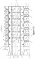
- a heat exchanger 5 is equipped with a mixing device 18 housed inside a header box 7 that includes the heat exchanger 5.
- the mixing device 18 is installed inside a chamber 9 delimited by a wall 7a of the header box 7 to supply refrigerant fluid FR to the tubes 12 of a bundle 6 of tubes 12 which open into the chamber 9 while being aligned in the longitudinal direction D2 of extension of the mixing device 18.
- the chamber 9 is delimited by eyelets 23 successively abutting and fixed to each other, in particular by brazing, in the longitudinal direction D2 of extension of the dispensing device 18.
- the eyelets thus form the wall 7a of the collector box delimiting the chamber 9.
- the eyelets 23 comprise collars 25 which are crossed by the distribution device 18 at a transverse distance relative to the longitudinal axis A1 of the conduit 14.
- the eyelets 23 are made at the end of plates 26 forming between them the tubes 12 of the bundle 6.
- the outlets 24 of the tubes 12 of the bundle 6 are thus formed by openings made through the wall 7a of the header box 7 delimiting the chamber 9, the outlets 24 of the tubes 12 of the bundle 6 being more specifically provided through the eyelets 23.
- the outlets 24 of the tubes 12 of the bundle 6 are configured as a funnel to increase the velocity of the refrigerant fluid FR evacuated from the chamber 9 towards tubes 12 of bundle 6.
- a space E1 for circulation of the refrigerant fluid FR around the first conduit 14 is thus formed inside the chamber 9 between the wall 7a of the manifold and the mixing device 18.
- the orifices 17 are oriented diametrically opposite outlets 24 of the tubes 12 of the bundle 6 with respect to the first longitudinal axis A1 of the first duct 14.
- the refrigerant fluid FR sprayed by the mixing device 18 is admitted inside the chamber 9, then circulates inside the space E1 around the conduit 14 to the outlets 24 of the tubes 12 of the bundle 6 for their supply with refrigerant fluid FR.
- the foregoing description clearly explains how the invention makes it possible to achieve the objectives it has set itself and in particular to propose a mixing device which homogenizes the distribution of the refrigerant fluid along the collector box to guarantee an admission quasi- identical refrigerant fluid in each tube of the bundle that includes the heat exchanger. Furthermore, the structural organization of the mixing device gives it easy adaptability that can be achieved at lower cost according to the layout of a specific heat exchanger, in particular with regard to the number of tubes of the bundle that it comprises.
- the mixing device which has just been described by way of non-limiting example and its use will be formed when the mixing device comprises a conduit whose internal face is configured as a means for mixing the refrigerant fluid between a liquid phase and a gaseous phase, the mixing means comprising at least one mixing member arranged on the internal face of the duct.
Landscapes
- Engineering & Computer Science (AREA)
- Physics & Mathematics (AREA)
- Thermal Sciences (AREA)
- Mechanical Engineering (AREA)
- General Engineering & Computer Science (AREA)
- Heat-Exchange Devices With Radiators And Conduit Assemblies (AREA)
- Details Of Heat-Exchange And Heat-Transfer (AREA)
Claims (15)
- Mischvorrichtung (18) zum Mischen einer Gasphase mit einer flüssigen Phase eines Kühlfluids (FR), die dazu ausgelegt ist, im Inneren eines Sammelkastens (7) eines Wärmetauschers (5) angeordnet zu sein, wobei die Mischvorrichtung (18) eine Leitung (14) mit einer Längsachse (A1) umfasst, die mit einer Einlassöffnung (10) zum Einlassen des Kühlfluids (FR) in die Leitung (14) und mit mindestens einer Öffnung (17) zum Sprühen des Kühlfluids (FR) aus der Leitung (14) ausgestattet ist; wobei die Leitung (14) mindestens ein Mischmittel (19) umfasst, das mehrere Mischorgane (19a, 19b) umfasst, die in die Innenfläche (14c) der Leitung (14) integriert und dazu geeignet sind, den Fluss des im Inneren der Leitung (14) strömenden Kühlfluids (FR) zu verändern, wobei die Dicke (Ep1, Ep2) der Wand (14a) der Leitung (14) in Ebenen (PP), die senkrecht zur Längsachse (A1) der Leitung (14) verlaufen und in Längsrichtung voneinander beabstandet sind, variiert, wobei die Dicke (Ep2) der Wand (14a) der Leitung (14) durch mindestens eines der Mischorgane (19a, 19b) erhöht ist, dadurch gekennzeichnet, dass das Mischmittel (19) im Inneren einer Aussparung (14b) angeordnet ist, wobei die Aussparung (14b) durch eine Wand (14a) der Leitung (14) begrenzt ist.
- Mischvorrichtung (18) nach Anspruch 1, wobei sich das Mischorgan (19a, 19b) im Inneren der Leitung (14) zumindest quer zu ihrer Längsachse (A1) und teilweise im Inneren der durch ihre Wand (14a) begrenzten Aussparung (14b) der Leitung (14) erstreckt und dabei ein Hindernis bildet, das einer laminaren Strömung des Kühlfluids (FR) im Inneren der Leitung (14) entgegenwirkt.
- Mischvorrichtung (18) nach einem der vorangehenden Ansprüche, wobei das Mischorgan (19a, 19b) in die Wand (14a) der Leitung (14) integriert ist.
- Mischvorrichtung (18) nach einem der vorangehenden Ansprüche, wobei sich mindestens eine Mischorgan (19a, 19b) senkrecht zur Längsachse (A1) der Leitung (14) erstreckt.
- Mischvorrichtung (18) nach einem der vorangehenden Ansprüche, wobei mindestens ein Mischorgan (19a, 19b) zumindest in einer Längsebene (PL) in Bezug auf die Längsachse (A1) der Leitung (14) geneigt ist und dabei eine Rampe (19c) zur Führung des Kühlfluids (FR) in Richtung der Öffnung (17) bildet.
- Mischvorrichtung (18) nach einem der vorangehenden Ansprüche, wobei mehrere Öffnungen (17) entlang der Leitung (14) entlang ihrer Längsachse (A1) verteilt sind.
- Mischvorrichtung (18) nach Anspruch 6, wobei die Öffnungen (17) entlang einer zur Längsachse (A1) der Leitung (14) parallelen Geraden (L1) verteilt sind.
- Mischvorrichtung (18) nach einem der vorangehenden Ansprüche, wobei in einer Längsebene (PL), die durch mindestens eine Öffnung (17) verläuft, mindestens ein Mischorgan (19a, 19b) stromaufwärts mindestens einer Öffnung (17) in einer von der Einlassöffnung (10) zur Öffnung (17) definierten Strömungsrichtung (S1) des Kühlfluids (FR) im Inneren der Leitung angeordnet ist.
- Mischvorrichtung (18) nach einem der vorangehenden Ansprüche, wobei in einer Längsebene (PL), die durch mindestens eine Öffnung (17) verläuft, mindestens ein Mischorgan (19a, 19b) zwischen mindestens zwei Öffnungen entlang der Längsachse der Wand angeordnet ist.
- Mischvorrichtung (18) nach einem der vorangehenden Ansprüche, wobei in einer Längsebene (PL), die durch mindestens eine Öffnung (17) verläuft, mehrere Mischorgane (19a, 19b) entlang der Längsachse (A1) der Leitung (14) verteilt sind.
- Mischvorrichtung (18) nach Anspruch 10, wobei in einer Längsebene (PL), die durch mindestens eine Öffnung (17) verläuft, die Mischorgane (19a, 19b) in einem ersten Trennabstand (Lg1) zwischen zwei benachbarten Mischorganen (19a, 19b) angeordnet sind, der gleich einem zweiten Trennabstand (Lg2) zwischen zwei benachbarten Öffnungen (17) ist.
- Mischvorrichtung (18) nach einem der Ansprüche 10 oder 11, wobei in einer Längsebene (PL), die durch mindestens eine Öffnung (17) verläuft, die Mischorgane (19a, 19b) in einem ersten Trennabstand (Lg1) zwischen zwei Mischorganen (19a, 19b) angeordnet sind, der größer als ein zweiter Trennabstand (Lg2) zwischen zwei benachbarten Öffnungen (17) ist.
- Mischvorrichtung (18) nach einem der vorangehenden Ansprüche, wobei das Mischorgan (19a) zu einem Ring (20a) ausgebildet ist, dessen Öffnung (21) einen durch ihn hindurch verlaufenden Durchgang für das Kühlfluid (FR) bildet.
- Mischvorrichtung (18) nach Anspruch 13, wobei die Abmessung der Öffnung (21) des Rings (20a) zwischen 10 % und 70 % der größten Abmessung (DT2) der Aussparung (14b) der Leitung (14) beträgt, gemessen in einer zur Längsachse (A1) der Leitung (14) senkrechten Ebene (PP).
- Wärmetauscher (5), umfassend einen Sammelkasten (7), der eine Kammer (9) bildet, die eine Mischvorrichtung (18) nach einem der Ansprüche 1 bis 14 aufnimmt, und umfassend Rohre (12) eines Bündels (6) von Rohren (12), die für ihre Versorgung mit Kühlfluid (FR) durch die Mischvorrichtung (18) in die Kammer (9) münden.
Applications Claiming Priority (2)
| Application Number | Priority Date | Filing Date | Title |
|---|---|---|---|
| FR1661756A FR3059407B1 (fr) | 2016-11-30 | 2016-11-30 | Dispositif de mixage d'un fluide refrigerant a l'interieur d'une boite collectrice d'un echangeur thermique |
| PCT/FR2017/053303 WO2018100301A1 (fr) | 2016-11-30 | 2017-11-30 | Dispositif de mixage d'un fluide réfrigérant à l'intérieur d'une boîte collectrice d'un échangeur thermique |
Publications (2)
| Publication Number | Publication Date |
|---|---|
| EP3548826A1 EP3548826A1 (de) | 2019-10-09 |
| EP3548826B1 true EP3548826B1 (de) | 2023-05-24 |
Family
ID=57909718
Family Applications (1)
| Application Number | Title | Priority Date | Filing Date |
|---|---|---|---|
| EP17817791.1A Active EP3548826B1 (de) | 2016-11-30 | 2017-11-30 | Vorrichtung zum mischen einer kühlflüssigkeit in einem sammelkasten eines wärmeaustauschers |
Country Status (4)
| Country | Link |
|---|---|
| EP (1) | EP3548826B1 (de) |
| CN (1) | CN110214257B (de) |
| FR (1) | FR3059407B1 (de) |
| WO (1) | WO2018100301A1 (de) |
Family Cites Families (10)
| Publication number | Priority date | Publication date | Assignee | Title |
|---|---|---|---|---|
| US1537553A (en) * | 1924-06-10 | 1925-05-12 | Samuel W Rushmore | Radiator |
| JPH04155194A (ja) * | 1990-10-17 | 1992-05-28 | Nippondenso Co Ltd | 熱交換器 |
| US6449979B1 (en) * | 1999-07-02 | 2002-09-17 | Denso Corporation | Refrigerant evaporator with refrigerant distribution |
| JP2002022313A (ja) * | 2000-07-06 | 2002-01-23 | Matsushita Refrig Co Ltd | 分流器 |
| CN101788242A (zh) * | 2009-03-25 | 2010-07-28 | 三花丹佛斯(杭州)微通道换热器有限公司 | 用于热交换器的制冷剂分配器和热交换器 |
| CN101691981B (zh) * | 2009-07-23 | 2011-12-07 | 三花丹佛斯(杭州)微通道换热器有限公司 | 具有改进的制冷剂流体分配均匀性的多通道换热器 |
| US20110290465A1 (en) | 2010-06-01 | 2011-12-01 | Delphi Technologies, Inc. | Orientation insensitive refrigerant distributor tube |
| US9772145B2 (en) * | 2011-06-24 | 2017-09-26 | Mitsubishi Electric Corporation | Flat plate heat exchanger having fluid distributor inside manifold |
| WO2014143951A2 (en) * | 2013-03-15 | 2014-09-18 | Parker-Hannifin Corporation | Refrigerant distributor |
| US10168084B2 (en) * | 2013-05-10 | 2019-01-01 | Denso Corporation | Refrigerant evaporator |
-
2016
- 2016-11-30 FR FR1661756A patent/FR3059407B1/fr active Active
-
2017
- 2017-11-30 WO PCT/FR2017/053303 patent/WO2018100301A1/fr not_active Ceased
- 2017-11-30 EP EP17817791.1A patent/EP3548826B1/de active Active
- 2017-11-30 CN CN201780083497.XA patent/CN110214257B/zh active Active
Also Published As
| Publication number | Publication date |
|---|---|
| EP3548826A1 (de) | 2019-10-09 |
| CN110214257B (zh) | 2021-08-17 |
| FR3059407B1 (fr) | 2019-10-18 |
| CN110214257A (zh) | 2019-09-06 |
| FR3059407A1 (fr) | 2018-06-01 |
| WO2018100301A1 (fr) | 2018-06-07 |
Similar Documents
| Publication | Publication Date | Title |
|---|---|---|
| FR3078550A1 (fr) | Bras d’alimentation pour injecteur de carburant a circuits multiples | |
| EP3318725B1 (de) | Anschlussanordnung für die kühlung einer turbine einer strömungsmaschine | |
| EP3548825B1 (de) | Vorrichtung zur verteilung eines kältemittels in einem sammelkasten eines wärmeaustauschers | |
| EP3548828A1 (de) | Vorrichtung zur verteilung eines kältemittels im innern von rohren eines einen kältemittelkreislauf bildenden wärmetauschers | |
| EP3983741B1 (de) | Wärmetauscher zur kühlung eines flugzeugtriebwerks | |
| FR3061280B1 (fr) | Dispositif de distribution d'un fluide refrigerant a l'interieur d'une boite collectrice d'un echangeur thermique pour une installation de conditionnement d'air d'un vehicule | |
| FR3059407B1 (fr) | Dispositif de mixage d'un fluide refrigerant a l'interieur d'une boite collectrice d'un echangeur thermique | |
| EP3548827B1 (de) | Vorrichtung zur verteilung eines kühlmittels in einem sammelkasten eines wärmeaustauschers für eine klimaanlage eines fahrzeugs | |
| FR3059408A1 (fr) | Dispositif de distribution d'un fluide refrigerant a l'interieur d'une boite collectrice d'un echangeur thermique | |
| FR3075349A1 (fr) | Dispositif de distribution d'un fluide refrigerant a l'interieur d'une boite collectrice d'un echangeur thermique, et boite collectrice equipee d'un tel dispositif de distribution | |
| FR3059405B1 (fr) | Dispositif de distribution d'un fluide refrigerant a l'interieur d'une boite collectrice d'un echangeur thermique | |
| FR3081985A1 (fr) | Distributeur de fluide, et echangeur thermique correspondant. | |
| WO2018100304A1 (fr) | Dispositif de distribution d'un fluide réfrigérant à l'intérieur d'une boîte collectrice d'un échangeur thermique | |
| EP3589826A1 (de) | Ventilationsvorrichtung für ein kraftfahrzeug | |
| EP3548823B1 (de) | Sammelrohr zur aufnahme eines kältemittels mit mindestens einer vorrichtung zur winkelpositionierung eines rohres | |
| FR3075345A1 (fr) | Boite collectrice d'un echangeur thermique logeant un dispositif de distribution d'un fluide refrigerant maintenu via un organe de centrage. | |
| FR3059409B1 (fr) | Dispositif d'homogeneisation de la distribution d'un fluide refrigerant a l'interieur de tubes d'un echangeur de chaleur constitutif d'un circuit de fluide refrigerant | |
| EP3589845A1 (de) | Belüftungsvorrichtung mit rohren mit optimierter neigung für ein wärmeaustauschmodul eines kraftfahrzeugs | |
| WO2018197818A1 (fr) | Dispositif de ventilation à tubes munis de moyens de guidage de flux d'air pour module d'échange de chaleur de véhicule automobile | |
| FR3061950A1 (fr) | Dispositif d’homogeneisation de la distribution d’un fluide refrigerant a l’interieur de tubes d’un echangeur de chaleur constitutif d’un circuit de fluide refrigerant | |
| FR3059406A1 (fr) | Dispositif de mixage d'un fluide refrigerant a l'interieur d'une boite collectrice d'un echangeur thermique pour une installation de conditionnement d'air d'un vehicule | |
| FR3061282A1 (fr) | Echangeur de chaleur constitutif d’un circuit de changeur fluide refrigerant | |
| FR3081516A1 (fr) | Dispositif de refroidissement des gaz recircules egr equipe d'un conduit peripherique de distribution de liquide de refroidissement |
Legal Events
| Date | Code | Title | Description |
|---|---|---|---|
| STAA | Information on the status of an ep patent application or granted ep patent |
Free format text: STATUS: UNKNOWN |
|
| STAA | Information on the status of an ep patent application or granted ep patent |
Free format text: STATUS: THE INTERNATIONAL PUBLICATION HAS BEEN MADE |
|
| PUAI | Public reference made under article 153(3) epc to a published international application that has entered the european phase |
Free format text: ORIGINAL CODE: 0009012 |
|
| STAA | Information on the status of an ep patent application or granted ep patent |
Free format text: STATUS: REQUEST FOR EXAMINATION WAS MADE |
|
| 17P | Request for examination filed |
Effective date: 20190614 |
|
| AK | Designated contracting states |
Kind code of ref document: A1 Designated state(s): AL AT BE BG CH CY CZ DE DK EE ES FI FR GB GR HR HU IE IS IT LI LT LU LV MC MK MT NL NO PL PT RO RS SE SI SK SM TR |
|
| AX | Request for extension of the european patent |
Extension state: BA ME |
|
| DAV | Request for validation of the european patent (deleted) | ||
| DAX | Request for extension of the european patent (deleted) | ||
| STAA | Information on the status of an ep patent application or granted ep patent |
Free format text: STATUS: EXAMINATION IS IN PROGRESS |
|
| 17Q | First examination report despatched |
Effective date: 20200716 |
|
| GRAP | Despatch of communication of intention to grant a patent |
Free format text: ORIGINAL CODE: EPIDOSNIGR1 |
|
| STAA | Information on the status of an ep patent application or granted ep patent |
Free format text: STATUS: GRANT OF PATENT IS INTENDED |
|
| INTG | Intention to grant announced |
Effective date: 20221017 |
|
| GRAJ | Information related to disapproval of communication of intention to grant by the applicant or resumption of examination proceedings by the epo deleted |
Free format text: ORIGINAL CODE: EPIDOSDIGR1 |
|
| STAA | Information on the status of an ep patent application or granted ep patent |
Free format text: STATUS: EXAMINATION IS IN PROGRESS |
|
| GRAP | Despatch of communication of intention to grant a patent |
Free format text: ORIGINAL CODE: EPIDOSNIGR1 |
|
| STAA | Information on the status of an ep patent application or granted ep patent |
Free format text: STATUS: GRANT OF PATENT IS INTENDED |
|
| INTC | Intention to grant announced (deleted) | ||
| INTG | Intention to grant announced |
Effective date: 20221223 |
|
| GRAS | Grant fee paid |
Free format text: ORIGINAL CODE: EPIDOSNIGR3 |
|
| GRAA | (expected) grant |
Free format text: ORIGINAL CODE: 0009210 |
|
| STAA | Information on the status of an ep patent application or granted ep patent |
Free format text: STATUS: THE PATENT HAS BEEN GRANTED |
|
| AK | Designated contracting states |
Kind code of ref document: B1 Designated state(s): AL AT BE BG CH CY CZ DE DK EE ES FI FR GB GR HR HU IE IS IT LI LT LU LV MC MK MT NL NO PL PT RO RS SE SI SK SM TR |
|
| REG | Reference to a national code |
Ref country code: GB Ref legal event code: FG4D Free format text: NOT ENGLISH |
|
| REG | Reference to a national code |
Ref country code: CH Ref legal event code: EP |
|
| REG | Reference to a national code |
Ref country code: DE Ref legal event code: R096 Ref document number: 602017069048 Country of ref document: DE |
|
| REG | Reference to a national code |
Ref country code: AT Ref legal event code: REF Ref document number: 1569743 Country of ref document: AT Kind code of ref document: T Effective date: 20230615 |
|
| REG | Reference to a national code |
Ref country code: IE Ref legal event code: FG4D Free format text: LANGUAGE OF EP DOCUMENT: FRENCH |
|
| P01 | Opt-out of the competence of the unified patent court (upc) registered |
Effective date: 20230528 |
|
| REG | Reference to a national code |
Ref country code: LT Ref legal event code: MG9D |
|
| REG | Reference to a national code |
Ref country code: NL Ref legal event code: MP Effective date: 20230524 |
|
| REG | Reference to a national code |
Ref country code: AT Ref legal event code: MK05 Ref document number: 1569743 Country of ref document: AT Kind code of ref document: T Effective date: 20230524 |
|
| PG25 | Lapsed in a contracting state [announced via postgrant information from national office to epo] |
Ref country code: SE Free format text: LAPSE BECAUSE OF FAILURE TO SUBMIT A TRANSLATION OF THE DESCRIPTION OR TO PAY THE FEE WITHIN THE PRESCRIBED TIME-LIMIT Effective date: 20230524 Ref country code: PT Free format text: LAPSE BECAUSE OF FAILURE TO SUBMIT A TRANSLATION OF THE DESCRIPTION OR TO PAY THE FEE WITHIN THE PRESCRIBED TIME-LIMIT Effective date: 20230925 Ref country code: NO Free format text: LAPSE BECAUSE OF FAILURE TO SUBMIT A TRANSLATION OF THE DESCRIPTION OR TO PAY THE FEE WITHIN THE PRESCRIBED TIME-LIMIT Effective date: 20230824 Ref country code: NL Free format text: LAPSE BECAUSE OF FAILURE TO SUBMIT A TRANSLATION OF THE DESCRIPTION OR TO PAY THE FEE WITHIN THE PRESCRIBED TIME-LIMIT Effective date: 20230524 Ref country code: ES Free format text: LAPSE BECAUSE OF FAILURE TO SUBMIT A TRANSLATION OF THE DESCRIPTION OR TO PAY THE FEE WITHIN THE PRESCRIBED TIME-LIMIT Effective date: 20230524 Ref country code: AT Free format text: LAPSE BECAUSE OF FAILURE TO SUBMIT A TRANSLATION OF THE DESCRIPTION OR TO PAY THE FEE WITHIN THE PRESCRIBED TIME-LIMIT Effective date: 20230524 |
|
| PG25 | Lapsed in a contracting state [announced via postgrant information from national office to epo] |
Ref country code: RS Free format text: LAPSE BECAUSE OF FAILURE TO SUBMIT A TRANSLATION OF THE DESCRIPTION OR TO PAY THE FEE WITHIN THE PRESCRIBED TIME-LIMIT Effective date: 20230524 Ref country code: PL Free format text: LAPSE BECAUSE OF FAILURE TO SUBMIT A TRANSLATION OF THE DESCRIPTION OR TO PAY THE FEE WITHIN THE PRESCRIBED TIME-LIMIT Effective date: 20230524 Ref country code: LV Free format text: LAPSE BECAUSE OF FAILURE TO SUBMIT A TRANSLATION OF THE DESCRIPTION OR TO PAY THE FEE WITHIN THE PRESCRIBED TIME-LIMIT Effective date: 20230524 Ref country code: LT Free format text: LAPSE BECAUSE OF FAILURE TO SUBMIT A TRANSLATION OF THE DESCRIPTION OR TO PAY THE FEE WITHIN THE PRESCRIBED TIME-LIMIT Effective date: 20230524 Ref country code: IS Free format text: LAPSE BECAUSE OF FAILURE TO SUBMIT A TRANSLATION OF THE DESCRIPTION OR TO PAY THE FEE WITHIN THE PRESCRIBED TIME-LIMIT Effective date: 20230924 Ref country code: HR Free format text: LAPSE BECAUSE OF FAILURE TO SUBMIT A TRANSLATION OF THE DESCRIPTION OR TO PAY THE FEE WITHIN THE PRESCRIBED TIME-LIMIT Effective date: 20230524 Ref country code: GR Free format text: LAPSE BECAUSE OF FAILURE TO SUBMIT A TRANSLATION OF THE DESCRIPTION OR TO PAY THE FEE WITHIN THE PRESCRIBED TIME-LIMIT Effective date: 20230825 |
|
| PG25 | Lapsed in a contracting state [announced via postgrant information from national office to epo] |
Ref country code: FI Free format text: LAPSE BECAUSE OF FAILURE TO SUBMIT A TRANSLATION OF THE DESCRIPTION OR TO PAY THE FEE WITHIN THE PRESCRIBED TIME-LIMIT Effective date: 20230524 |
|
| PG25 | Lapsed in a contracting state [announced via postgrant information from national office to epo] |
Ref country code: SK Free format text: LAPSE BECAUSE OF FAILURE TO SUBMIT A TRANSLATION OF THE DESCRIPTION OR TO PAY THE FEE WITHIN THE PRESCRIBED TIME-LIMIT Effective date: 20230524 |
|
| PG25 | Lapsed in a contracting state [announced via postgrant information from national office to epo] |
Ref country code: SM Free format text: LAPSE BECAUSE OF FAILURE TO SUBMIT A TRANSLATION OF THE DESCRIPTION OR TO PAY THE FEE WITHIN THE PRESCRIBED TIME-LIMIT Effective date: 20230524 Ref country code: SK Free format text: LAPSE BECAUSE OF FAILURE TO SUBMIT A TRANSLATION OF THE DESCRIPTION OR TO PAY THE FEE WITHIN THE PRESCRIBED TIME-LIMIT Effective date: 20230524 Ref country code: RO Free format text: LAPSE BECAUSE OF FAILURE TO SUBMIT A TRANSLATION OF THE DESCRIPTION OR TO PAY THE FEE WITHIN THE PRESCRIBED TIME-LIMIT Effective date: 20230524 Ref country code: EE Free format text: LAPSE BECAUSE OF FAILURE TO SUBMIT A TRANSLATION OF THE DESCRIPTION OR TO PAY THE FEE WITHIN THE PRESCRIBED TIME-LIMIT Effective date: 20230524 Ref country code: DK Free format text: LAPSE BECAUSE OF FAILURE TO SUBMIT A TRANSLATION OF THE DESCRIPTION OR TO PAY THE FEE WITHIN THE PRESCRIBED TIME-LIMIT Effective date: 20230524 Ref country code: CZ Free format text: LAPSE BECAUSE OF FAILURE TO SUBMIT A TRANSLATION OF THE DESCRIPTION OR TO PAY THE FEE WITHIN THE PRESCRIBED TIME-LIMIT Effective date: 20230524 |
|
| REG | Reference to a national code |
Ref country code: DE Ref legal event code: R097 Ref document number: 602017069048 Country of ref document: DE |
|
| PLBE | No opposition filed within time limit |
Free format text: ORIGINAL CODE: 0009261 |
|
| STAA | Information on the status of an ep patent application or granted ep patent |
Free format text: STATUS: NO OPPOSITION FILED WITHIN TIME LIMIT |
|
| 26N | No opposition filed |
Effective date: 20240227 |
|
| PG25 | Lapsed in a contracting state [announced via postgrant information from national office to epo] |
Ref country code: SI Free format text: LAPSE BECAUSE OF FAILURE TO SUBMIT A TRANSLATION OF THE DESCRIPTION OR TO PAY THE FEE WITHIN THE PRESCRIBED TIME-LIMIT Effective date: 20230524 |
|
| PG25 | Lapsed in a contracting state [announced via postgrant information from national office to epo] |
Ref country code: SI Free format text: LAPSE BECAUSE OF FAILURE TO SUBMIT A TRANSLATION OF THE DESCRIPTION OR TO PAY THE FEE WITHIN THE PRESCRIBED TIME-LIMIT Effective date: 20230524 Ref country code: IT Free format text: LAPSE BECAUSE OF FAILURE TO SUBMIT A TRANSLATION OF THE DESCRIPTION OR TO PAY THE FEE WITHIN THE PRESCRIBED TIME-LIMIT Effective date: 20230524 |
|
| REG | Reference to a national code |
Ref country code: CH Ref legal event code: PL |
|
| PG25 | Lapsed in a contracting state [announced via postgrant information from national office to epo] |
Ref country code: MC Free format text: LAPSE BECAUSE OF FAILURE TO SUBMIT A TRANSLATION OF THE DESCRIPTION OR TO PAY THE FEE WITHIN THE PRESCRIBED TIME-LIMIT Effective date: 20230524 |
|
| PG25 | Lapsed in a contracting state [announced via postgrant information from national office to epo] |
Ref country code: LU Free format text: LAPSE BECAUSE OF NON-PAYMENT OF DUE FEES Effective date: 20231130 |
|
| PG25 | Lapsed in a contracting state [announced via postgrant information from national office to epo] |
Ref country code: CH Free format text: LAPSE BECAUSE OF NON-PAYMENT OF DUE FEES Effective date: 20231130 |
|
| GBPC | Gb: european patent ceased through non-payment of renewal fee |
Effective date: 20231130 |
|
| PG25 | Lapsed in a contracting state [announced via postgrant information from national office to epo] |
Ref country code: MC Free format text: LAPSE BECAUSE OF FAILURE TO SUBMIT A TRANSLATION OF THE DESCRIPTION OR TO PAY THE FEE WITHIN THE PRESCRIBED TIME-LIMIT Effective date: 20230524 Ref country code: LU Free format text: LAPSE BECAUSE OF NON-PAYMENT OF DUE FEES Effective date: 20231130 Ref country code: CH Free format text: LAPSE BECAUSE OF NON-PAYMENT OF DUE FEES Effective date: 20231130 |
|
| REG | Reference to a national code |
Ref country code: BE Ref legal event code: MM Effective date: 20231130 |
|
| REG | Reference to a national code |
Ref country code: IE Ref legal event code: MM4A |
|
| PG25 | Lapsed in a contracting state [announced via postgrant information from national office to epo] |
Ref country code: IE Free format text: LAPSE BECAUSE OF NON-PAYMENT OF DUE FEES Effective date: 20231130 |
|
| PG25 | Lapsed in a contracting state [announced via postgrant information from national office to epo] |
Ref country code: GB Free format text: LAPSE BECAUSE OF NON-PAYMENT OF DUE FEES Effective date: 20231130 |
|
| PG25 | Lapsed in a contracting state [announced via postgrant information from national office to epo] |
Ref country code: BE Free format text: LAPSE BECAUSE OF NON-PAYMENT OF DUE FEES Effective date: 20231130 |
|
| PG25 | Lapsed in a contracting state [announced via postgrant information from national office to epo] |
Ref country code: IE Free format text: LAPSE BECAUSE OF NON-PAYMENT OF DUE FEES Effective date: 20231130 Ref country code: GB Free format text: LAPSE BECAUSE OF NON-PAYMENT OF DUE FEES Effective date: 20231130 Ref country code: BE Free format text: LAPSE BECAUSE OF NON-PAYMENT OF DUE FEES Effective date: 20231130 |
|
| PG25 | Lapsed in a contracting state [announced via postgrant information from national office to epo] |
Ref country code: BG Free format text: LAPSE BECAUSE OF FAILURE TO SUBMIT A TRANSLATION OF THE DESCRIPTION OR TO PAY THE FEE WITHIN THE PRESCRIBED TIME-LIMIT Effective date: 20230524 |
|
| PG25 | Lapsed in a contracting state [announced via postgrant information from national office to epo] |
Ref country code: BG Free format text: LAPSE BECAUSE OF FAILURE TO SUBMIT A TRANSLATION OF THE DESCRIPTION OR TO PAY THE FEE WITHIN THE PRESCRIBED TIME-LIMIT Effective date: 20230524 |
|
| PG25 | Lapsed in a contracting state [announced via postgrant information from national office to epo] |
Ref country code: CY Free format text: LAPSE BECAUSE OF FAILURE TO SUBMIT A TRANSLATION OF THE DESCRIPTION OR TO PAY THE FEE WITHIN THE PRESCRIBED TIME-LIMIT; INVALID AB INITIO Effective date: 20171130 |
|
| PG25 | Lapsed in a contracting state [announced via postgrant information from national office to epo] |
Ref country code: HU Free format text: LAPSE BECAUSE OF FAILURE TO SUBMIT A TRANSLATION OF THE DESCRIPTION OR TO PAY THE FEE WITHIN THE PRESCRIBED TIME-LIMIT; INVALID AB INITIO Effective date: 20171130 |
|
| PG25 | Lapsed in a contracting state [announced via postgrant information from national office to epo] |
Ref country code: TR Free format text: LAPSE BECAUSE OF FAILURE TO SUBMIT A TRANSLATION OF THE DESCRIPTION OR TO PAY THE FEE WITHIN THE PRESCRIBED TIME-LIMIT Effective date: 20230524 |
|
| PGFP | Annual fee paid to national office [announced via postgrant information from national office to epo] |
Ref country code: DE Payment date: 20251117 Year of fee payment: 9 |
|
| PGFP | Annual fee paid to national office [announced via postgrant information from national office to epo] |
Ref country code: FR Payment date: 20251128 Year of fee payment: 9 |