EP3548825B1 - Dispositif de distribution d'un fluide réfrigérant à l'intérieur d'une boîte collectrice d'un échangeur thermique - Google Patents
Dispositif de distribution d'un fluide réfrigérant à l'intérieur d'une boîte collectrice d'un échangeur thermique Download PDFInfo
- Publication number
- EP3548825B1 EP3548825B1 EP17817790.3A EP17817790A EP3548825B1 EP 3548825 B1 EP3548825 B1 EP 3548825B1 EP 17817790 A EP17817790 A EP 17817790A EP 3548825 B1 EP3548825 B1 EP 3548825B1
- Authority
- EP
- European Patent Office
- Prior art keywords
- conduit
- pipe
- distribution device
- refrigerant fluid
- distribution
- Prior art date
- Legal status (The legal status is an assumption and is not a legal conclusion. Google has not performed a legal analysis and makes no representation as to the accuracy of the status listed.)
- Active
Links
- 239000003507 refrigerant Substances 0.000 title claims description 130
- 238000009826 distribution Methods 0.000 claims description 156
- 239000012530 fluid Substances 0.000 claims description 132
- 238000004891 communication Methods 0.000 claims description 15
- 239000000463 material Substances 0.000 claims description 14
- 230000000295 complement effect Effects 0.000 claims description 5
- 238000000638 solvent extraction Methods 0.000 claims description 2
- 238000005728 strengthening Methods 0.000 claims 1
- 125000006850 spacer group Chemical group 0.000 description 42
- 239000012071 phase Substances 0.000 description 26
- 239000007791 liquid phase Substances 0.000 description 24
- 238000000034 method Methods 0.000 description 16
- 238000009434 installation Methods 0.000 description 10
- 238000004378 air conditioning Methods 0.000 description 8
- 238000005219 brazing Methods 0.000 description 8
- 238000005304 joining Methods 0.000 description 7
- 238000001816 cooling Methods 0.000 description 6
- 238000002156 mixing Methods 0.000 description 6
- 238000000265 homogenisation Methods 0.000 description 5
- 239000007788 liquid Substances 0.000 description 5
- 239000000203 mixture Substances 0.000 description 5
- 239000000470 constituent Substances 0.000 description 4
- 238000004519 manufacturing process Methods 0.000 description 4
- 210000000056 organ Anatomy 0.000 description 4
- 230000006978 adaptation Effects 0.000 description 3
- 238000000151 deposition Methods 0.000 description 3
- XAGFODPZIPBFFR-UHFFFAOYSA-N aluminium Chemical compound [Al] XAGFODPZIPBFFR-UHFFFAOYSA-N 0.000 description 2
- 229910052782 aluminium Inorganic materials 0.000 description 2
- 230000015572 biosynthetic process Effects 0.000 description 2
- 230000001788 irregular Effects 0.000 description 2
- 238000003754 machining Methods 0.000 description 2
- 239000007769 metal material Substances 0.000 description 2
- 230000008520 organization Effects 0.000 description 2
- 239000008188 pellet Substances 0.000 description 2
- 238000007789 sealing Methods 0.000 description 2
- 239000007921 spray Substances 0.000 description 2
- 238000005507 spraying Methods 0.000 description 2
- 238000004804 winding Methods 0.000 description 2
- 239000000110 cooling liquid Substances 0.000 description 1
- 230000001419 dependent effect Effects 0.000 description 1
- 229940082150 encore Drugs 0.000 description 1
- 239000000835 fiber Substances 0.000 description 1
- 239000006260 foam Substances 0.000 description 1
- 230000005484 gravity Effects 0.000 description 1
- 238000010438 heat treatment Methods 0.000 description 1
- 239000008240 homogeneous mixture Substances 0.000 description 1
- 238000012423 maintenance Methods 0.000 description 1
- 238000012986 modification Methods 0.000 description 1
- 230000004048 modification Effects 0.000 description 1
- 239000012768 molten material Substances 0.000 description 1
- 238000005192 partition Methods 0.000 description 1
- 230000002093 peripheral effect Effects 0.000 description 1
- 230000000704 physical effect Effects 0.000 description 1
- 230000001737 promoting effect Effects 0.000 description 1
- 238000004080 punching Methods 0.000 description 1
- 230000003014 reinforcing effect Effects 0.000 description 1
- 238000007493 shaping process Methods 0.000 description 1
- 238000009423 ventilation Methods 0.000 description 1
Images


Classifications
-
- F—MECHANICAL ENGINEERING; LIGHTING; HEATING; WEAPONS; BLASTING
- F28—HEAT EXCHANGE IN GENERAL
- F28F—DETAILS OF HEAT-EXCHANGE AND HEAT-TRANSFER APPARATUS, OF GENERAL APPLICATION
- F28F9/00—Casings; Header boxes; Auxiliary supports for elements; Auxiliary members within casings
- F28F9/02—Header boxes; End plates
- F28F9/026—Header boxes; End plates with static flow control means, e.g. with means for uniformly distributing heat exchange media into conduits
- F28F9/027—Header boxes; End plates with static flow control means, e.g. with means for uniformly distributing heat exchange media into conduits in the form of distribution pipes
- F28F9/0273—Header boxes; End plates with static flow control means, e.g. with means for uniformly distributing heat exchange media into conduits in the form of distribution pipes with multiple holes
-
- F—MECHANICAL ENGINEERING; LIGHTING; HEATING; WEAPONS; BLASTING
- F25—REFRIGERATION OR COOLING; COMBINED HEATING AND REFRIGERATION SYSTEMS; HEAT PUMP SYSTEMS; MANUFACTURE OR STORAGE OF ICE; LIQUEFACTION SOLIDIFICATION OF GASES
- F25B—REFRIGERATION MACHINES, PLANTS OR SYSTEMS; COMBINED HEATING AND REFRIGERATION SYSTEMS; HEAT PUMP SYSTEMS
- F25B39/00—Evaporators; Condensers
- F25B39/02—Evaporators
- F25B39/028—Evaporators having distributing means
-
- F—MECHANICAL ENGINEERING; LIGHTING; HEATING; WEAPONS; BLASTING
- F28—HEAT EXCHANGE IN GENERAL
- F28F—DETAILS OF HEAT-EXCHANGE AND HEAT-TRANSFER APPARATUS, OF GENERAL APPLICATION
- F28F9/00—Casings; Header boxes; Auxiliary supports for elements; Auxiliary members within casings
- F28F9/007—Auxiliary supports for elements
-
- F—MECHANICAL ENGINEERING; LIGHTING; HEATING; WEAPONS; BLASTING
- F28—HEAT EXCHANGE IN GENERAL
- F28F—DETAILS OF HEAT-EXCHANGE AND HEAT-TRANSFER APPARATUS, OF GENERAL APPLICATION
- F28F9/00—Casings; Header boxes; Auxiliary supports for elements; Auxiliary members within casings
- F28F9/02—Header boxes; End plates
- F28F9/026—Header boxes; End plates with static flow control means, e.g. with means for uniformly distributing heat exchange media into conduits
- F28F9/028—Header boxes; End plates with static flow control means, e.g. with means for uniformly distributing heat exchange media into conduits by using inserts for modifying the pattern of flow inside the header box, e.g. by using flow restrictors or permeable bodies or blocks with channels
-
- F—MECHANICAL ENGINEERING; LIGHTING; HEATING; WEAPONS; BLASTING
- F28—HEAT EXCHANGE IN GENERAL
- F28F—DETAILS OF HEAT-EXCHANGE AND HEAT-TRANSFER APPARATUS, OF GENERAL APPLICATION
- F28F2240/00—Spacing means
Definitions
- the field of the present invention is that of heat exchangers equipping air conditioning installations for a vehicle, in particular an automobile.
- the invention relates more specifically to the methods of distributing a refrigerant fluid inside a collector box included in such a heat exchanger.
- a vehicle is commonly equipped with an air conditioning installation to thermally treat the air present or sent into the passenger compartment of the vehicle.
- an air conditioning installation comprises a closed circuit inside which a refrigerant fluid circulates. Successively following the direction of circulation of the refrigerant fluid through it, the circuit essentially comprises a compressor, a condenser, an expander and at least one heat exchanger.
- the heat exchanger commonly comprises a bundle of tubes interposed between a collector box and a refrigerant fluid return box.
- the refrigerant fluid is admitted through an inlet port inside a collector box, circulates along successive paths in the tubes of the bundle between the collector box and a return box, then is evacuated out of the exchanger thermal through an outlet mouth.
- the outlet can be provided through the collector box or through the return box.
- the heat exchanger is for example an evaporator providing a heat exchange between the refrigerant fluid and an air flow passing through it.
- the refrigerant circulates inside the bundle tubes and the air flow circulates along the bundle tubes for its cooling.
- a problem posed lies in the fact that the refrigerant fluid is in the liquid/gaseous two-phase state when it is admitted inside the heat exchanger. Due to the difference in physical properties between liquid and gas, the refrigerant tends to separate into its liquid phase and its gas phase.
- This phenomenon generates heterogeneity in the temperature of the air flow which has passed through the heat exchanger in operation. This heterogeneity complicates the thermal management of the device which receives the heat exchanger and ultimately implies temperature differences between two zones of the passenger compartment, while the same air flow temperature is required.
- the present invention relates to a device for distributing a refrigerant fluid configured to be housed inside a collector box of a heat exchanger.
- a device for distributing a refrigerant fluid configured to be housed inside a collector box of a heat exchanger.
- Such a device as provided for in the preamble to claim 1, is known from FROM 10 2011 088635 .
- the invention also relates to a method of manufacturing a distribution device according to the invention.
- the invention also relates to a heat exchanger comprising a collector box housing a distribution device of the invention.
- the heat exchanger is in particular arranged to equip an air conditioning installation of a vehicle, in particular an automobile.
- An aim of the invention is to perfect the homogeneity of the temperature of the heat exchanger in operation and finally to improve its efficiency.
- Another aim of the invention is to propose a device for distributing the refrigerant fluid which can be obtained industrially at lower costs.
- Another aim of the invention is to propose a device for distributing the refrigerant fluid whose organization allows its easy adaptation and at lower costs to heat exchangers of various structures.
- the distribution device of the invention comprises at least one conduit extended along a longitudinal axis.
- the conduit has at one of its longitudinal ends an inlet mouth for admitting the refrigerant fluid into the conduit.
- the conduit also includes at least one orifice for evacuating the refrigerant fluid out of the conduit.
- the conduit is in particular closed at the other of its longitudinal ends to force the spray through the orifice of the refrigerant fluid admitted into the conduit.
- the distribution device comprises the conduit provided with the inlet mouth and the orifice, called the first conduit.
- the distribution device further comprises at least a second conduit which surrounds the first conduit and which comprises at least one passage for evacuating the refrigerant fluid from the distribution device.
- the distribution device further comprises at least one spacing device which provides between the first conduit and the second conduit at least one communication channel between at least one orifice and at least one passage.
- the distribution device comprises the first conduit which is surrounded by the second conduit at a transverse distance relative to the longitudinal axis of the first conduit, so as to provide the channel between them.
- the channel is thus delimited between the first conduit and the second conduit.
- the spacing device is interposed between the first conduit and the second conduit to keep them at a transverse distance from each other while providing the channel between them.
- the channel forms an intermediate chamber between the first conduit and the second conduit, the refrigerant fluid evacuated out of the first conduit through the orifice(s) being able to circulate inside the channel prior to its evacuation out of the second conduit through the or passages.
- the communication between the orifice(s) and the passage(s) is understood to be fluid communication between them. Such communication is capable of providing circulation of a fluid, in particular the refrigerant fluid, between the orifice(s) and the passage(s), the outlets of which communicate with the channel interposed between the orifice(s) and the passage(s).
- the channel forms an intermediate chamber for communicating the orifice(s) with the passage(s).
- the channel forms an intermediate chamber between the recess of the first conduit with which the channel is in communication via the orifice(s) and the exterior of the distribution device with which the channel is in communication via the orifice(s). passages.
- the notion of communication between organs such as for example the channel, the orifice(s), the passage(s), the first conduit and/or the second conduit is considered as fluid communication allowing the passage of a fluid from one to the other of the organs, in particular the refrigerant fluid.
- the refrigerant fluid is able to be admitted inside the distribution device through the inlet mouth and to then circulate inside the first conduit, then to be sprayed out of the first conduit towards the channel through the orifice(s). Then the refrigerant fluid is able to circulate inside the channel and then to be sprayed out of the channel through the passage(s) towards the outside of the second conduit or in other words towards the outside of the distribution device.
- the distribution device is capable of comprising N1 conduits successively surrounding the first conduit at a transverse distance from its longitudinal axis, at least one spacing device providing N1-1 stepped channels through which the orifice(s) are in communication with the passage(s) opening out of the distribution device.
- the spacing device is in particular configured to maintain a predefined transverse positioning between the first conduit and the second conduit and to arrange the channel by providing a homogeneous distribution of the refrigerant fluid from the passage towards the tubes of a bundle of tubes which comprises a heat exchanger equipped with a collector box housing the distribution device of the invention.
- Such homogeneous distribution is assessed with regard to the homogeneity of the refrigerant fluid between its liquid phase and its gas phase and/or with regard to a homogeneous supply of refrigerant fluid along the distribution device towards each of the tubes of the tube bundle .
- the relative positioning between the first conduit and the second conduit provided by the spacing device makes it possible in particular to position and maintain the second conduit relative to the longitudinal axis of the first conduit according to a desired configuration of the channel .
- the channel is in particular arranged to optimize the circulation path of the refrigerant fluid inside the distribution device in order to improve the mixing of the refrigerant fluid between its liquid phase and its gas phase prior to its evacuation from the distribution device.
- the configuration of the spacer device can advantageously be determined and/or chosen from various predefined configurations depending on the arrangement of the heat exchanger. Particular consideration is given to the configuration of the box collector housing the distribution device, which is dependent on the methods of supplying refrigerant fluid to the tubes of the heat exchanger bundle opening onto the collector box, in particular with regard to the number of tubes in the bundle and the configuration of their outlet on the collector box.
- the configuration of the orifice through which the refrigerant fluid is evacuated out of the conduit can be advantageously differentiated from the configuration of the passage through which the refrigerant fluid is distributed out of the distribution device towards the tubes of the bundle which comprises a heat exchanger equipped with the distribution device.
- the configuration, the number and/or the distribution of orifices along the first conduit can be determined independently of the configuration, the number and/or the distribution of passages along the second conduit.
- the orifice(s) can be specifically configured to optimize the mixture obtained between a liquid phase and a gas phase of the refrigerant fluid discharged from the first conduit.
- the passage(s) can be specifically configured to make the distribution of the refrigerant fluid more reliable and more uniform to each of the tubes in the bundle.
- the methods of evacuating the refrigerant fluid out of the first conduit through the orifice(s) are thus advantageously separated from the methods of evacuating the refrigerant fluid out of the distribution device.
- the passages can in particular be individually assigned to the tubes of the bundle, for example by being placed in direct communication with their outlet on the collector box.
- the performance of the heat exchanger is increased.
- the temperature of the air passing through the heat exchanger is considerably balanced along all the tubes of the tube bundle.
- the temperature of a cooling liquid circulating through a hydraulic cooling circuit extending at least partly along the heat exchanger is also considerably balanced during its passage along the assembly. tubes of the tube bundle.
- the orifice(s) and the passage(s) are capable of being individually oriented perpendicularly or of being inclined relative to the longitudinal axis of the first conduit in the direction of any of its longitudinal ends.
- the orifices are for example aligned along a first straight line parallel to the longitudinal axis of the first conduit and/or the passages for example aligned along a second straight line parallel to the longitudinal axis of the first conduit, in other words parallel to the first straight line.
- the orifices and passages are also capable of being angularly offset relative to each other by an angle less than or equal to 180° around the longitudinal axis of the first conduit, which determines the path of circulation of the refrigerant fluid at inside the canal.
- the orifices and the passages are for example angularly offset by 180° relative to the longitudinal axis of the first conduit, the orifices being diametrically arranged opposite the passages relative to the longitudinal axis of the first conduit.
- the spacing device is advantageously integrated into the distribution device by being secured in particular to the first conduit and to the second conduit.
- the interposition of the spacing device between the first conduit and the second conduit can be carried out by one or more components arranged inside the channel and/or at at least one of the longitudinal ends of the distribution device. .
- the spacer device is preferably in contact with the first conduit and the second conduit. Such contacting provides sealing of the channel between the first conduit and the second conduit forcing the spray of the refrigerant fluid through the orifice(s) and through the passage(s).
- Bringing the first conduit and the second conduit into contact via the spacing device can also be used to secure the conduits together via the spacing device.
- the spacing device advantageously forms a member for securing the first conduit in the second conduit.
- the joining of the conduits via the spacing device and the structural arrangement of the spacing device can be exploited to strengthen the distribution device. This is particularly useful in the case where the distribution device has a substantial longitudinal extension while being adapted to equip a heat exchanger comprising a large number of tubes in the bundle, such as, for example, between 20 and 50 tubes.
- the spacing device advantageously forms a reinforcing member of the distribution device.
- the spacing device forms in particular a member for positioning the first conduit in the second conduit in a direction transverse to the longitudinal axis of the first conduit.
- the spacing device forms a centering member, in particular coaxial, of the first conduit in the second conduit.
- the coaxial position of the first conduit and the second conduit facilitates the arrangement at lower costs of the distribution device and facilitates its arrangement providing an efficient mixture of the refrigerant fluid between its liquid phase and its gas phase and providing homogeneous distribution of the refrigerant fluid along of the distribution device through the passages.
- the first conduit and the second conduit are kept eccentric with respect to each other by the spacing device.
- the configuration of the channel is then asymmetrical along at least one plane transverse to the longitudinal axis of the first conduit.
- the channel formed by the spacing device between the first conduit and the second conduit is capable of being of regular conformation or of being of irregular conformation along the longitudinal axis of the first conduit or in other terms along the distribution device.
- the channel is thus configured according to the extension length of the distribution device, taking into account the velocity of the refrigerant fluid circulating inside the channel to achieve homogeneous distribution of the refrigerant fluid through each of the passages.
- the spacing device may include various components interposed between the first conduit and the second conduit to provide the channel between them.
- the spacing device comprises at least one component interposed between the first conduit and the second conduit.
- At least one component of the spacer device is incorporated into the first conduit and/or the second conduit.
- Several components of the spacer device may have different structures.
- the spacing device is likely to comprise at least two components of similar configurations or of differentiated configurations.
- At least one first component of the spacer device may have a configuration of its own and at least one second component of the spacer device may have a configuration that is different from the configuration of the first component.
- At least one component of the spacer device is provided inside the channel.
- at least one component of the spacing device is interposed between the peripheral walls of the first conduit and the second conduit extending along the longitudinal axis of the first conduit or in other words along the length of the device. distribution.
- several components of the spacer device are distributed at a distance from each other along the longitudinal axis of the first conduit.
- the spacing device comprises several components distributed inside the channel along the first conduit and cooperating with each other to reinforce the maintenance of the transverse distance between the first conduit and the second conduit over the whole of the length of the dispensing device.
- At least one component of the spacing device forms a partitioning wall of the channel which it divides into at least two successive cells along the longitudinal axis of the first conduit. At least one orifice and at least one passage open into each of the cells.
- the channel is compartmentalized into at least two cells independent of each other, that is to say being isolated from each other with respect to a communication between them in the volume forming the channel provided between the conduits.
- the channel can be compartmentalized into N2 cells by several components of the spacing device distributed along the distribution device. N2 can then advantageously correspond to the number of tubes of the bundle to be supplied with refrigerant fluid from a collector box equipped with the distribution device of the invention.
- the refrigerant fluid admitted inside the first conduit is thus sprayed inside each of the cells independently of each other and is then sprayed out of the distribution device from each of the cells.
- the homogeneity of the distribution of the refrigerant fluid towards each of the tubes of the bundle is thus reinforced.
- At least one partition wall is advantageously formed by a component of the spacer device of closed annular conformation.
- a component of the spacing device is in particular arranged in a closed ring, and can be produced by deformation of the wall of the first conduit and/or the second conduit.
- Such a component of the spacing device arranged in a closed ring is also likely to be formed from a block of added material, bar brazing in particular, on the first conduit and/or on the second conduit prior to joining the conduits together. via the spacer.
- the closed annular conformation of such a component matches in particular the transverse conformation of the channel delimited between the walls of the first conduit and the second conduit.
- the closed annular conformation of such a component is likely to be regular around the longitudinal axis of the first conduit, being of circular conformation.
- the closed annular conformation of such a component is also likely to be irregular around the longitudinal axis of the first conduit, for example being of oblong conformation.
- the spacing device comprises several components angularly distributed around the longitudinal axis of the first conduit.
- the spacer device For example, several components of the spacer device are angularly distributed around a circle centered on the longitudinal axis of the first conduit.
- At least two components of the spacing device are angularly distributed around the longitudinal axis of the first conduit and are distributed at a distance from one another along the longitudinal axis of the first conduit.
- At least two components of the spacer device are shaped into a ring portion surrounding at least partly the first conduit.
- the conformation of at least one component of the spacer device in a ring portion, or in other words in an open ring, allows circulation of the refrigerant fluid through the channel along the distribution device.
- a component shaped like a ring portion extends in particular over an angular range less than or equal to 180° around the longitudinal axis of the first conduit.
- a plurality of components each shaped into a ring portion are preferably angularly offset at the periphery of the first conduit around its longitudinal axis while being arranged at a distance from each other along the distribution device.
- At least one component shaped like a ring portion is arranged in an open torus through which the first conduit extends.
- the edge of the torus defining its winding on itself is preferably truncated in the area of its opening and/or at its periphery, to reinforce the contact of the component with the first conduit and/or the second conduit.
- the spacing device will include a member providing a stop with a small contact surface between the first conduit and the second conduit at least in a direction transverse to the longitudinal axis of the first conduit.
- At least one of the components of the spacing device is for example formed of a spacer attached inside the channel between the first conduit and the second conduit.
- spacer we will understand a component of the spacing device formed of a block of material inserted in interposition between the first conduit and the second conduit.
- the spacing device therefore comprises at least one spacer.
- At least one of the components of the spacing device is for example still formed by a relief coming from the wall of the first conduit and/or the second conduit.
- At least one component of the spacer device is capable of being formed of a spacer and at least one other component of the spacer device is capable of being formed of a relief.
- At least one component of the spacing device is formed of a spacer housed in the channel interposed between the first conduit and the second conduit.
- the spacer is for example formed by adding material to the first conduit and/or to the second conduit.
- a supply of material may result from a deposit of material or from the fixing of a block of material on the first conduit and/or on the second conduit.
- At least one spacer is formed by depositing material and/or by at least one block of added material.
- At least one spacer forms a component of the spacer device permeable to the refrigerant fluid to allow circulation of the refrigerant fluid through it.
- a permeable component is capable of extending at least partly inside the channel along the longitudinal axis of the first conduit.
- An advantage of organizing at least one component of the spacer device as a spacer is to allow a mixer forming the spacer to be housed inside the channel.
- the mixer is a member configured to disrupt a laminar flow of a fluid, in particular the refrigerant fluid.
- the mixer provides a mixture of a liquid phase with a gas phase of the refrigerant fluid circulating inside the channel.
- the mixture of the refrigerant fluid between its liquid phase and its gas phase obtained by its spraying through the orifices is thus completed inside the channel when the refrigerant fluid passes through the mixer.
- the mixer is for example formed of a porous body.
- the mixer is formed of a body comprising obstacles preventing a laminar flow of the refrigerant fluid inside the second chamber.
- the mixer is formed of a body shaped like a helix or composed of a plurality of helices joined together along their winding axis, being successively radially offset relative to each other.
- the mixer is for example still made of a foam formed from a tangle of fibers or threads, in particular metallic.
- a first step of homogenization of the refrigerant fluid between its liquid phase and its gas phase is carried out during the evacuation of the refrigerant fluid through the orifices towards the channel.
- a second step of homogenization of the refrigerant fluid between its liquid phase and its gas phase is then carried out during its circulation inside the channel.
- the channel preferably houses at least one component of the spacer device structured as a mixer to increase the mixing of the refrigerant fluid between its liquid phase and its gas phase prior to its evacuation from the distribution device.
- At least one spacer is at least partly structured as a mixer of the refrigerant fluid between its liquid phase and its gas phase.
- At least one component of the spacing device is formed of a relief resulting from deformation of material from the wall of the first conduit and/or from the wall of the second conduit.
- a relief can be formed at lower cost, for example by stamping, by crushing, by machining and/or by shaping the wall of the first conduit and/or the wall of the second conduit.
- At least one component of the spacing device is capable of being provided at one and/or the other of the longitudinal ends of the first conduit and the second conduit closest to each other.
- At least one component of the spacing device is interposed between a longitudinal end of the first conduit and a longitudinal end of the second conduit closest to each other along the longitudinal axis of the first conduit. In other words still, at least one component of the spacing device is interposed between the longitudinal ends of the first conduit and the second conduit located at the same longitudinal end of the distribution device.
- At least one component of the spacing device is capable of being interposed between each of the longitudinal ends of the first conduit and the second conduit closest to each other along the longitudinal axis of the first conduit.
- at least one component of the spacing device is capable of being interposed between the longitudinal ends of the first conduit and the second conduit at each of the longitudinal ends of the distribution device.
- At least one component of the spacing device is formed of at least one end piece fitted to at least one of the longitudinal ends of any one of the first conduit and/or the second conduit.
- the end piece is housed in a recess of complementary shape which comprises at least one of the longitudinal ends of any other of the first conduit and/or the second conduit.
- the tip is for example shaped like a cone, a sphere or a portion of a sphere, a parallelepiped or even has an ovoid shape.
- the first conduit and the second conduit have in particular cross sections of complementary shape providing the channel between them.
- the first conduit has a circular cross section.
- the second conduit has a circular cross section.
- the first conduit has an oblong cross section.
- the second conduit has an oblong cross section.
- first conduit and/or the second conduit are capable of presenting independently of one another or jointly a circular and/or oblong cross section. More particularly according to one embodiment, each of the first conduit and the second conduit is capable of having a circular conformation. According to another embodiment, each of the first conduit and the second conduit is likely to have an oblong conformation. According to one embodiment, any one of the first conduit or the second conduit is likely to have a circular conformation and any other of the first conduit or the second conduit is likely to have an oblong formation.
- the invention also relates to a method of manufacturing a distribution device as just described.
- the method comprises a joining operation between the first conduit and the second conduit via the spacing device.
- the spacing device is particularly secured to the first conduit and/or the second conduit.
- the method comprises an operation of forming at least one spacer on the first conduit and/or on the second conduit, then an operation of assembling the conduits together by threading the first conduit into the second conduit.
- the method comprises an operation of assembling the conduits together via at least one end piece installed at at least one of the longitudinal ends of the distribution device.
- the operation of joining the conduits together is advantageously carried out by brazing, in particular in the oven, during an operation of assembling the constituent parts of the distribution device.
- the constituent members of the distribution device include in particular at least the first conduit, the second conduit and the spacing device, which are advantageously made of metallic material, in particular based on aluminum, to obtain their connection between them by brazing.
- the present invention also relates to a heat exchanger comprising a collector box comprising a wall delimiting a chamber which houses a distribution device as has just been described.
- the chamber communicates in particular with a plurality of tubes of a bundle of tubes of the heat exchanger to be supplied with the refrigerant fluid distributed by the distribution device.
- the distribution device is in contact with the wall of the collector box via the first conduit, the second conduit and/or the spacing device. Such contact provides in particular at least one connection zone between the distribution device and the wall of the collector box, in particular by brazing.
- the contact between the wall of the collector box and the distribution device is for example at least one contact between the wall of the collector box and the ends of the first conduit and/or the second conduit.
- the contact between the wall of the collector box and the distribution device can be made via end pieces fitted to the longitudinal ends of the distribution device. Such tips are potentially or not components of the spacer device. It is thus provided that the distribution device is maintained inside the collector box at least via each of its longitudinal ends.
- the contact between the wall of the collector box and the distribution device is for example still at least one contact between the wall of the collector box and the wall of the second conduit surrounding the first conduit. It is thus provided that the distribution device is maintained inside the collector box along its length or in other words along the longitudinal axis of the first conduit.
- the wall of the collector box is delimited by eyelets each having an opening through which extends the distribution device which is in contact with the edge of the openings.
- the tubes are provided between plates stacked in the longitudinal direction of the distribution device.
- the plates are incorporated into the collector box and have eyelets delimiting the first chamber.
- the eyelets are crossed by the distribution device and are extended by extensions of the plates providing the tubes of the bundle between them.
- a second chamber is provided inside the first conduit and communicates via at least one orifice with a third chamber provided between the first conduit and the second conduit.
- the third chamber is notably formed by the channel which extends between the first conduit and the second conduit.
- the third chamber communicates via at least one passage with the chamber, then called the first chamber, delimited by the wall of the collector box.
- the refrigerant fluid is able to circulate from the second chamber to the third chamber then to the first chamber.
- the distribution device is capable of occupying the entire volume of the first chamber in a direction transverse to the longitudinal axis of the first conduit.
- the outlets of the tubes into the space can advantageously be provided through the wall of the collector box.
- the second conduit comprises a plurality of passages opening individually in a sealed manner directly towards each of the tubes of the bundle.
- the refrigerant fluid is then able to be directly distributed to the tubes of the bundle without circulating inside the first chamber.
- the distribution of the refrigerant fluid to each of the tubes in the bundle is thus made more reliable and promotes a uniform supply of refrigerant fluid to all of the tubes in the bundle.
- the distribution device is also capable of partially occupying the volume of the first chamber in a direction transverse to the longitudinal axis of the first conduit.
- the outlets of the tubes into the space can be provided through the wall of the collector box.
- the tubes of the bundle pass through the wall of the collector box, their outlets then being arranged inside the first chamber.
- the distribution device partially occupies the volume of the first chamber in a direction transverse to the longitudinal axis of the first conduit.
- a space for circulation of the refrigerant fluid is provided inside the first chamber between the distribution device and the outlets of the bundle tubes.
- the outlets of the bundle tubes are arranged at a distance from the distribution device and more particularly at a distance from the passages.
- the refrigerant fluid evacuated from the distribution device is then able to circulate inside the first chamber at least partly around the distribution device prior to its distribution towards the tubes of the bundle.
- the mixing of the refrigerant fluid between its liquid phase and its gas phase is thus completed during its circulation inside the first chamber, prior to the distribution of the refrigerant fluid towards the tubes of the bundle.
- the distribution device partially occupies the volume of the first chamber in a direction transverse to the longitudinal axis of the first conduit.
- the tubes pass through the wall of the collector box to emerge inside the first chamber.
- the outlets of the bundle tubes are placed directly in watertight communication with a passage assigned to them.
- the refrigerant fluid is capable of being directly distributed from each of the passages of the distribution device to each of the outlets of the tubes to promote their homogeneous supply of refrigerant fluid.
- the passages are for this purpose adjoined in a sealed manner to the outlets of the tubes of the bundle so as to authorize tight communication between them.
- the second conduit can for this purpose be secured to the tubes at the edge of their outlets, in particular by brazing.
- each passage opens out of the first chamber towards a single tube of the bundle of tubes.
- the number of passages in particular corresponds to the number of tubes in the bundle to be supplied with refrigerant fluid.
- a second longitudinal end of the first conduit opposite its first longitudinal end communicating with the inlet mouth is preferably closed to force the distribution of the refrigerant fluid out of the first conduit towards the channel through the orifice(s).
- the longitudinal ends of the second conduit are preferably closed to force the distribution of the refrigerant fluid out of the channel through the passage(s) towards the outside of the second conduit or in other words out of the distribution device towards the outlets of the tubes of the second conduit. beam.
- the heat exchanger is more particularly configured to be used as an evaporator.
- the heat exchanger can be used to cool a flow of air passing through it or to cool a liquid dedicated to cooling an organ, such as at least one battery of a vehicle providing the energy necessary at least in part to its propulsion.
- the invention also relates to a refrigerant fluid circuit comprising at least one compressor, a condenser, an expansion device and a heat exchanger conforming to the invention, through which a refrigerant fluid passes.
- the invention also relates to a ventilation, heating and/or air conditioning installation, or air conditioning installation, configured to equip a vehicle.
- the air conditioning installation of the invention comprises at least one heat exchanger according to the invention.
- an air conditioning installation for a vehicle comprises a closed circuit 1 inside which a refrigerant fluid FR circulates.
- circuit 1 essentially comprises, successively in the direction S1 of circulation of the refrigerant fluid FR, a compressor 2, a condenser 3 or gas cooler, an expansion member 4 and at least one heat exchanger 5
- a minimal architecture of circuit 1 is given for information purposes only and is not restrictive as to the scope of the invention with regard to various potential architectures of circuit 1.
- the heat exchanger 5 is for example dedicated to cooling an air flow FA passing through it, as illustrated in the figure 2 .
- Such an air flow FA is used in particular to thermally treat the air in the passenger compartment of the vehicle or, for example, to cool a component of the vehicle in operation.
- the heat exchanger 5 is dedicated to the cooling of a liquid used to cool a component of the vehicle in operation, such as one or more batteries supplying electrical energy to a propulsion electric motor of the vehicle.
- the heat exchanger 5 comprises a bundle 6 interposed between a collector box 7 and a return box 8.
- the collector box 7 extends in a longitudinal direction D1 oriented perpendicular to a direction D3 of extension of the tubes 12 of the bundle 6 between the collector box 7 and the return box 8.
- the collector box 7 delimits a chamber 9 supplied with refrigerant fluid FR through an inlet mouth 10.
- the refrigerant fluid FR circulates inside the heat exchanger 5 to cool at least the tubes 12 of the bundle 6, then is evacuated from the heat exchanger 5 through an outlet 11.
- the outlet 11 is provided through the collector box 7, which implies that the heat exchanger 5 is a “U” circulation heat exchanger.
- the outlet 11 can be provided through the return box 8, which then implies that the heat exchanger 5 is an “I” circulation heat exchanger.
- the heat exchanger 5 is of the U-shaped circulation type of the refrigerant fluid FR.
- the heat exchanger 5 is intended for cooling an air flow FA.
- the tubes 12 of the bundle 6 typically comprise fins 13 promoting the heat exchange between the air flow FA and the tubes 12 of the bundle 6.
- the air flow FA passes through the bundle 6 transversely to the general plane P1 of the exchanger thermal 5, flowing along the tubes 12.
- the refrigerant fluid FR circulates from the collector box 7 towards a first layer 12a of tubes 12 of the bundle 6 dedicated to supplying the return box 8 with refrigerant fluid FR. Then the refrigerant fluid FR circulates from the return box 8 towards the collector box 7 through a second layer 12b of tubes 12 of the bundle 6. The first layer 12a and the second layer 12b are superimposed following the direction of circulation of the flow of air FA through the heat exchanger 5.
- Such a configuration of the heat exchanger 5 makes it particularly useful to obtain a homogeneous distribution of the refrigerant fluid FR between its liquid phase and its gas phase and a homogeneous distribution of the refrigerant fluid FR along the collector box 7 towards each of the tubes 12 of the first layer 12a of the bundle 6.
- the example described of the architecture of the heat exchanger 5 and the methods of circulation of the refrigerant fluid FR between the collector box 7 and the return box 8, are nevertheless given in indicative title and are not restrictive as to the scope of the invention.
- the chamber 9 houses a distribution device 18 extending in a longitudinal direction D2 parallel to the longitudinal direction D1 of extension of the collector box 7.
- the distribution device 18 comprises a conduit 14 extending along a longitudinal axis A1 between a first end 15 and a second end 16 of the conduit 14.
- the conduit 14 is in particular intended to provide homogenization of the refrigerant fluid FR between its liquid phase and its gas phase during its evacuation from the conduit 14.
- the longitudinal axis A1 of the conduit 14 is oriented parallel to the direction D1 of extension of the collector box 7 and defines the longitudinal direction D2 of extension of the distribution device 18.
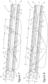
- the distribution device 18 is potentially centered inside of the collector box 7 as illustrated on the figure 1 or to be eccentric inside the collector box 7 relative to a median longitudinal axis A2 of extension of the collector box 7 as illustrated in the figure 2 .
- a first longitudinal end 15 of the conduit 14 comprises the inlet mouth 10 for supplying refrigerant fluid FR to the distribution device 18 via the conduit 14.
- the inlet mouth 10 is capable of receiving the refrigerant fluid FR from the exterior of the distribution device 18 either directly or via a junction member of the heat exchanger 5 with the fluidic circuit 1 illustrated in the figure 1 .
- the second end 16 of the conduit 14 is closed.
- At least one orifice 17 is provided through the conduit 14 for the evacuation of the refrigerant fluid FR from the conduit 14 towards the chamber 9.
- the conduit preferably comprises a plurality of orifices 17 provided over at least part of its length for promote the homogenization of the refrigerant fluid evacuated along the conduit 14 between its liquid phase and its gas phase.
- FIG. 3 to 12 various embodiments of a dispensing device 18 according to the invention are illustrated.
- the distribution devices 18 illustrated on the figures 3 to 12 are configured to equip a heat exchanger according to the invention, as illustrated for example on the figures 13 and 14 .
- the distribution devices 18 illustrated on the figures 3 to 12 are arranged to be housed in the collector box 7 from which the tubes 12 of the first layer 12a of tubes 12 of the bundle 6 which the heat exchanger 5 comprises are supplied with refrigerant fluid FR.
- the distribution devices 18 comprise the conduit 14, hereinafter designated first conduit 14, which is provided with the inlet mouth 10 and a plurality of orifices 17 through which the refrigerant fluid FR is evacuated out of the first conduit 14.
- the distribution devices 18 also comprise a second conduit 19 which houses the first conduit 14 and which comprises passages 20 through which the refrigerant fluid FR intended to be admitted inside the distribution devices 18 is sprayed towards the tubes 12 of bundle 6.
- the second conduit 19 surrounds the first conduit 14 at a distance from one another in a direction transverse DT to the longitudinal axis A1 of the first conduit 14.
- the distribution devices 18 comprise a spacing device 21 interposed between the first conduit 14 and the second conduit 19.
- the spacing device 21 thus provides between the first conduit 14 and the second conduit 19 a channel 22 inside which the refrigerant fluid FR is intended to circulate prior to its spraying towards the tubes 12 of bundle 6.
- the second conduit 19 and the first conduit 14 are shown coaxial.
- the orifices 17 are aligned along a first straight line L1 and the passages 20 are aligned along a second straight line L2.
- the first straight line L1 and the second straight line L2 are parallel to the longitudinal axis A1 of the first conduit 14.
- the orifices 17 and the passages 20 are angularly offset over an angular range less than or equal to 180° around the longitudinal axis A1 of the conduit 14.
- the path traveled by the refrigerant fluid FR inside the channel 22 around the conduit 14 , and thus inside the distribution devices 18, is optimized to increase the mixing between a liquid phase and a gas phase of the refrigerant fluid FR sprayed out of the first conduit 14 through the orifices 17.
- the orifices 17 and the passages 20 are angularly offset by 180° around the longitudinal axis A1 of the first conduit 14, following an angle B1 referenced on the Figure 14 .
- the orifices 17 and the passages 20 are angularly offset by an angle B2 less than 180° around the longitudinal axis of the first conduit 14.
- the refrigerant fluid FR is potentially entrained by its gas phase inside the channel 22 around the first conduit 14 over an angular range greater than 180°.
- the number of orifices 17 and the number of passages 20 are different.
- the interposition of the channel 22 between the orifices 17 and the passages 20 makes it possible to dissociate the methods of obtaining a homogeneous mixture between a gas phase and a liquid phase of the refrigerant fluid FR sprayed through the orifices 17, from the distribution methods of the refrigerant fluid FR through the passages 20 out of the distribution devices 18 towards each of the tubes 12 of the bundle 6.
- the refrigerant fluid FR evacuated from the first conduit 14 through the orifices 17 is sprayed inside the channel 22, circulates inside the channel 22 at least partly around the first conduit 14 up to the passages 20 for its evacuation outside distribution devices 18.
- the refrigerant fluid FR is mixed between its liquid phase and its gas phase at the outlet of the first conduit 14 through the orifices 17.
- the circulation of the refrigerant fluid FR inside the channel 22 makes it possible to optimize the mixing of the refrigerant fluid FR between its liquid phase and its gas phase prior to its evacuation from the distribution devices 18 through the passages 20.
- At least one mixer participating in the formation of the spacing device 21 can be advantageously housed inside the channel 22 to further increase the mixing of the refrigerant fluid FR between a liquid phase and a gas phase inside. of channel 22.
- the first conduit 14 and the second conduit 19 have an annular conformation centered on the longitudinal axis A1 of the first conduit 14.
- the transverse section of the conduits 14,19 is of circular conformation.
- the transverse section of the conduits 14,19 is of oblong conformation.
- the spacing device 21 is advantageously used to secure the first conduit 14 and the second conduit 19 to each other, maintaining them firmly in their relative transverse position.
- the spacing device 21 is in particular made from a metallic material, such as aluminum-based, allowing it to be brazed on the first conduit 14 and on the second conduit 14 with which the spacing device 21 is placed in contact .
- the distribution devices 18 can thus be reinforced by the spacing device 21, particularly in the event of a significant extension of a distribution device 18 intended to supply a significant number of tubes 12 of the bundle 6.
- the spacing device 21 comprises various components 21a, 21b, 21c to maintain the first conduit 14 and the second conduit 19 at a distance from each other in the transverse direction DT.
- the components 21a, 21b, 21c of the spacing device 21 can be variously structured and/or be variously positioned inside the distribution devices 18.
- Components 21a, 21b, 21c of the same spacing device 21 can be arranged differently and be used in combinations at least two by two to maintain the first conduit 14 and the second conduit 19 at a determined transverse distance, to the extent where such combinations are compatible with each other.
- components 21a, 21b of the spacer devices 21 are arranged inside the channel 22, being interposed between the wall 14a of the first conduit 14 and the wall 19a of the second conduit 19.
- components 21a, 21b of the spacing devices 21 are arranged at a distance T1 from each other along the distribution devices 18 or in other words along the longitudinal axis A1 of the first conduit 14.
- the components 21a, 21b of the spacing devices 21 can be distributed inside the channel 22 equidistant or at differentiated distances between at least two neighboring components 21a, 21b along the longitudinal axis A1 of the first conduit 14. In d In other words, the distance T1 of distributions of the components 21a, 21b along the longitudinal axis A1 of the first conduit 14 is likely to vary along the distribution devices 18.
- components 21a, 21b of the spacer device 21 each extend partially around the first conduit 14 along a circumference centered on the longitudinal axis A1 of the first conduit 14.
- the partial extension of the components 21a, 21b around of the first conduit 14 is designed to authorize overall occupation of the channel 22 by the refrigerant fluid FR in a continuous volume.
- the components 21a, 21b of the spacing device 21 are then distributed angularly around the first conduit 14, without prejudging their individual distribution positions along the longitudinal axis A1 of the first conduit 14.
- the components 21a, 21b of the spacing device 21 cooperate with each other at least in pairs to maintain the first conduit 14 and the second conduit 19 at a distance from each other in the transverse direction DT.
- components 21a, 21b of the spacing device 21 are arranged in tabs 23 configured as a stop member with a small contact surface with the first conduit 14 and the second conduit 19. At least one set of tabs 23 cooperating with each other provides the relative positioning between the first conduit 14 and the second conduit 19 transversely to the longitudinal axis A1 of the first conduit 14.
- the tabs 23 are for example at least three in number, being distributed at 120° around the longitudinal axis A1 of the first conduit 14.
- the cleats 23 are four in number and are distributed at 90° around the longitudinal axis A1 of the first conduit 14.
- components 21a of the spacer device 21 are arranged in a ring portion 25 or in other words in an open ring.
- the ring portions 25 each extend around the longitudinal axis A1 of the first conduit 14 over an angular range less than 180°, such as for example an angular range of around 120° as illustrated.
- components 21a, 21b of the spacer devices 21 are of closed annular conformation, each extending around the first conduit 14 along the entirety of a circumference centered on the longitudinal axis A1 of the first conduit 14.
- Such components 21a, 21b of the spacing devices 21 are in particular shaped into closed rings 26, which surround the first conduit 14 while being closed on themselves around the first conduit 14.
- the channel 22 is thus compartmentalized along the longitudinal axis A1 of the first conduit into a plurality of cells 22a independent of each other. At least one passage 20 and at least one orifice 17 open into each of the cells 22a.
- the refrigerant fluid FR can thus be admitted inside the channel 22 in a plurality of distinct fractions of refrigerant fluid FR which circulate independently of each other inside the cells 22a.
- the division of the channel 22 into cells 22a independent of each other makes it possible to better control the homogeneity of the quantities of refrigerant fluid FR evacuated from the distribution devices 18 through each of the passages 20.
- the homogeneous supply of the tubes 12 of the bundle 6 in FR refrigerant fluid is reinforced, which makes it possible to increase the performance of the heat exchanger 5.
- the closed rings 26 are defined by a circular transverse profile.
- the closed rings 26 have a transverse profile shaped like an open torus.
- the toroids are preferably flattened at their contact faces with the first conduit 14 and the second conduit 19, to reinforce the extent of contact of the closed rings 26 with the first conduit 14 and the second conduit 19.
- components of the spacer devices 21 are arranged in spacers 21a.
- the spacers 21a are in particular formed by blocks of material attached by brazing to the first conduit 14 and/or to the second conduit 19.
- the spacers 21a can also be formed by depositing molten material on the wall 14a of the first conduit 14 and /or on the wall 19a of the second conduit 19.
- the spacers 21a are formed from rings 25, 26 attached by brazing to the first conduit 14 and/or to the second conduit 19.
- the spacers 21a are formed from pellets 27 attached by brazing or by depositing material on the first conduit 14 and/or on the second conduit 19.
- the pellets 27 are configured as a tab 23, for example being shaped into a spherical cap such that illustrated on the figure 5 or in parallelepipeds more or less elongated along the longitudinal axis A1 of the first conduit 14, as illustrated in the Figure 6 and the figure 13 .
- components of the spacing device 21 are formed by reliefs 21b coming from the wall 14a of the first conduit 14 or from the wall 19a of the second conduit 19.
- the reliefs 21b can be shaped into closed rings 26 as illustrated on the figures 9 And 11 or in cleats 23 as illustrated on the figures 7, 8 , 10 And 12 .
- the reliefs 21b can for example be created by machining or by deformation of the walls 14a, 19a of the conduits referenced 14 and 19.
- the reliefs 21b are formed by deformation of the first conduit 14 and/or the second conduit 19.
- the reliefs 21b are formed by deformation of the second conduit 19.
- the reliefs 21b are formed by deformation of the first conduit 14 or the second conduit 19.
- the deformations of the first conduit 14 and/or the second conduit 19 can be carried out by punching or by stamping, as illustrated in the figures 7, 8 And 10 .
- the reliefs are then, for example, shaped into bosses.
- the deformations of the first conduit 14 and/or the second conduit 19 can also be carried out by pushing back material as illustrated in the figures 9 And 11 .
- the reliefs 21b are then for example shaped into closed rings 26.
- the deformations of the first conduit 14 and/or the second conduit 19 can also be carried out by localized crushing of the first conduit 14 and/or the second conduit 19 transversely on either side of the longitudinal axis A1 of the first conduit 14.
- the reliefs 21b are formed by crushing the first conduit 14, being shaped in particular into bosses.
- the spacing devices 21 comprise at least one component 21c formed of a tip 29a interposed between longitudinal ends 16a, 16b of the first conduit 14 and the second conduit 19 close to each other along the longitudinal axis A1 of the first conduit 14.
- the end piece 29a is of conical conformation to reinforce the rigor of the transverse positioning, in particular coaxial, between the first conduit 14 and the second conduit 19.
- the end piece 29a is for example provided at one of the longitudinal ends 16a of the first conduit 14, and further forms a closing member of this longitudinal end 16a of the first conduit 14.
- the end piece 29a is housed inside a recess 29b of complementary shape provided at the longitudinal end 16b of the second conduit 19, with which the end piece 29a cooperates to maintain the first conduit 14 and the second conduit 19 at a transverse distance relative to the longitudinal axis A1 of the first conduit 14.
- the different examples of realization of the spacing devices 21 illustrated on the figures 3 to 14 are not exhaustive and are not restrictive as to the scope of the invention.
- the different illustrated and described embodiments of the spacing devices 21 present in particular the advantages of being achievable at lower costs and of industrially facilitating the adaptation of the distribution devices 18 according to different heat exchangers 5 of various structures, including in particular tubes 12 of beam 6 to be supplied with FR refrigerant fluid in specific numbers.
- spacing device 21 in accordance with the invention can be implemented to provide relative positioning between the first conduit 14 and the second conduit 19 transversely to the longitudinal axis A1 of the first conduit 14, providing a channel 22 between them.
- heat exchangers 5 are equipped with distribution devices 18 according to the invention.
- the distribution devices 18 are housed inside the collector box 7, the wall 7a of which provides the chamber 9 onto which the tubes 12 of the bundle 6 of the heat exchangers 5 open.
- a space for circulation of the refrigerant fluid FR sprayed out of the distribution device 18 is provided inside the chamber 9.
- the refrigerant fluid FR is capable of circulating inside the chamber 9 at least partly around the second conduit 19 or in other words at least partly around the distribution device 18, prior to its admission to the tubes 12 of the bundle 6.
- the passages 20 are directly communicating with the outlets 24 of the tubes 12 of the bundle 6 on the chamber 9.
- the passages 20 being attached to the outlets 24 of the tubes 12 of the bundle 6.
- the edge of the passages 20 can advantageously be brazed along the edges outlets 24 of the tubes 12 of the bundle 6 on the collector box 7, to provide effective sealing of the joining zone between the passages 20 and the outlets 24 of the tubes 12 of the bundle 6.
- the distribution of the refrigerant fluid FR to each of the tubes 12 of the bundle 6 is thus obtained particularly reliable and efficient, and the homogeneous supply of refrigerant fluid FR to the tubes 12 of the bundle 6 is obtained particularly efficient along the distribution device 18.
- the preceding description clearly explains how the invention makes it possible to achieve the objectives it has set for itself and in particular to propose a distribution device which homogenizes the distribution of the refrigerant fluid along the collector box to guarantee an almost identical refrigerant fluid in each tube of the bundle that comprises the heat exchanger.
- the structural organizations of the distribution device give them adaptability at lower costs according to the arrangement of a specific heat exchanger, in particular with regard to the number of tubes of the bundle which it comprises.
Description
- Le domaine de la présente invention est celui des échangeurs thermiques équipant les installations de conditionnement d'air pour un véhicule, notamment automobile. L'invention relève plus spécifiquement des modalités de distribution d'un fluide réfrigérant à l'intérieur d'une boîte collectrice que comporte un tel échangeur thermique.
- Un véhicule est couramment équipé d'une installation de conditionnement d'air pour traiter thermiquement l'air présent ou envoyé dans l'habitacle du véhicule. Une telle installation comprend un circuit fermé à l'intérieur duquel circule un fluide réfrigérant. Successivement suivant le sens de circulation du fluide réfrigérant à son travers, le circuit comprend essentiellement un compresseur, un condenseur, un détendeur et au moins un échangeur thermique.
- L'échangeur thermique comporte couramment un faisceau de tubes interposés entre une boîte collectrice et une boîte de renvoi du fluide réfrigérant. Le fluide réfrigérant est admis à travers une bouche d'entrée à l'intérieur d'une boîte collectrice, circule suivant des chemins successifs dans les tubes du faisceau entre la boîte collectrice et une boîte de renvoi, puis est évacué hors de l'échangeur thermique à travers une bouche de sortie. La bouche de sortie est susceptible d'être ménagée à travers la boîte collectrice ou à travers la boîte de renvoi.
- L'échangeur thermique est par exemple un évaporateur procurant un échange thermique entre le fluide réfrigérant et un flux d'air le traversant. Dans ce cas, le fluide réfrigérant circule à l'intérieur des tubes du faisceau et le flux d'air circule le long des tubes du faisceau pour son refroidissement.
- Un problème posé réside dans le fait que le fluide réfrigérant est à l'état diphasique liquide/gazeux lorsqu'il est admis à l'intérieur de l'échangeur thermique. Du fait de la différence entre les propriétés physiques entre le liquide et le gaz, le fluide réfrigérant tend à se séparer entre sa phase liquide et sa phase gazeuse.
- Il en résulte une hétérogénéité de l'alimentation des tubes du faisceau au regard des différentes phases du fluide réfrigérant, selon leur position par rapport à la bouche d'entrée du fluide réfrigérant à l'intérieur de la boîte collectrice. Plus particulièrement, les tubes du faisceau situés au plus proche de la bouche d'entrée sont principalement alimentés en liquide et inversement les tubes du faisceau les plus éloignés de la bouche d'entrée sont principalement alimentés en gaz.
- Ce phénomène génère une hétérogénéité de la température du flux d'air qui a traversé l'échangeur thermique en fonctionnement. Cette hétérogénéité complique la gestion thermique de l'appareil qui reçoit l'échangeur thermique et in fine implique des écarts de températures entre deux zones de l'habitacle, alors que la même température de flux d'air est demandée.
- Il est connu de loger un conduit pourvu d'une pluralité d'orifices à l'intérieur d'une boîte collectrice. Le fluide réfrigérant en phase liquide est ainsi projeté à travers les orifices sous forme de gouttelettes sur la totalité de la longueur du conduit, tel qu'il ressort du document
EP 2 392 886 A2 . - Une telle organisation n'est cependant pas optimale du point de vue de l'homogénéisation de la température du flux d'air en sortie de l'échangeur thermique.
- La présente invention a pour objet un dispositif de distribution d'un fluide réfrigérant configuré pour être logé à l'intérieur d'une boîte collectrice d'un échangeur thermique. Un tel dispositif, tel que le prévoit le préambule de la revendication 1, est connu de
DE 10 2011 088635 . L'invention a aussi pour objet un procédé de fabrication d'un dispositif de distribution conforme à l'invention. - L'invention a aussi pour objet un échangeur thermique comprenant une boîte collectrice logeant un dispositif de distribution de l'invention. L'échangeur thermique est notamment agencé pour équiper une installation de conditionnement d'air d'un véhicule, notamment automobile.
- Un but de l'invention est de parfaire l'homogénéité de la température de l'échangeur thermique en fonctionnement et finalement d'améliorer son rendement.
- Il est plus spécifiquement visé par l'invention de parfaire la distribution du fluide réfrigérant dans la boîte collectrice de manière homogène entre sa phase liquide et sa phase gazeuse.
- Il est encore plus spécifiquement visé par l'invention de procurer une alimentation homogène en fluide réfrigérant des tubes du faisceau interposés entre la boîte collectrice et la boîte de renvoi de l'échangeur thermique.
- Un autre but de l'invention est de proposer un dispositif de distribution du fluide réfrigérant pouvant être obtenu industriellement à moindres coûts.
- Il est notamment recherché une obtention à moindres coûts et une efficacité du dispositif de distribution, permettant d'obtenir une homogénéisation performante du fluide réfrigérant entre sa phase liquide et sa phase gazeuse, et une distribution homogène du fluide réfrigérant à l'intérieur de chacun des tubes du faisceau de l'échangeur thermique
- Un autre but de l'invention est de proposer un dispositif de distribution du fluide réfrigérant dont l'organisation permette son adaptation aisée et à moindres coûts à des échangeurs thermiques de structures diverses.
- Une telle diversité de structures des échangeurs thermiques est notamment à apprécier au regard du nombre de tubes du faisceau qu'ils comportent, des modalités de circulation du fluide réfrigérant à l'intérieur de l'échangeur thermique et/ou des positions relatives entre la bouche d'entrée et la bouche de sortie du fluide réfrigérant que comporte l'échangeur thermique.
- Le dispositif de distribution de l'invention comprend au moins un conduit étendu suivant un axe longitudinal. Le conduit comporte à l'une de ses extrémités longitudinales une bouche d'entrée pour l'admission du fluide réfrigérant dans le conduit. Le conduit comporte aussi au moins un orifice pour l'évacuation du fluide réfrigérant hors du conduit. Le conduit est notamment fermé à l'autre de ses extrémités longitudinales pour forcer la pulvérisation à travers l'orifice du fluide réfrigérant admis dans le conduit.
- Selon l'invention, le dispositif de distribution comprend le conduit pourvu de la bouche d'entrée et de l'orifice, dit premier conduit. Le dispositif de distribution comprend en outre au moins un deuxième conduit qui entoure le premier conduit et qui comporte au moins un passage pour l'évacuation du fluide réfrigérant hors du dispositif de distribution. Le dispositif de distribution comprend encore au moins un dispositif d'espacement qui ménage entre le premier conduit et le deuxième conduit au moins un canal de communication entre au moins un orifice et au moins un passage.
- En d'autres termes, le dispositif de distribution comprend le premier conduit qui est entouré par le deuxième conduit à distance transverse par rapport à l'axe longitudinal du premier conduit, de manière à ménager le canal entre eux. Le canal est ainsi délimité entre le premier conduit et le deuxième conduit. Le dispositif d'espacement est interposé entre le premier conduit et le deuxième conduit pour les maintenir à distance transverse l'un de l'autre en ménageant le canal entre eux. Le canal forme une chambre intermédiaire entre le premier conduit et le deuxième conduit, le fluide réfrigérant évacué hors du premier conduit à travers le ou les orifices étant apte à circuler à l'intérieur du canal préalablement à son évacuation hors du deuxième conduit à travers le ou les passages.
- La communication entre le ou les orifices et le ou les passages est comprise comme étant une communication fluidique entre eux. Une telle communication est apte à procurer une circulation d'un fluide, notamment le fluide réfrigérant, entre le ou les orifices et le ou les passages, dont les débouchés communiquent avec le canal interposé entre le ou les orifices et le ou les passages. Le canal forme une chambre intermédiaire de mise en communication du ou des orifices avec le ou les passages. En d'autres termes, le canal forme une chambre intermédiaire entre l'évidement du premier conduit avec lequel le canal est en communication via le ou les orifices et l'extérieur du dispositif de distribution avec lequel le canal est en communication via le ou les passages.
- D'une manière générale et par la suite, la notion de communication entre des organes, telles que par exemple le canal, le ou les orifices, le ou les passages, le premier conduit et/ou le deuxième conduit est considérée comme une communication fluidique autorisant le passage d'un fluide de l'un à l'autre des organes, notamment le fluide réfrigérant.
- Ainsi, le fluide réfrigérant est apte à être admis à l'intérieur du dispositif de distribution à travers la bouche d'entrée et à circuler ensuite à l'intérieur du premier conduit, puis à être pulvérisé hors du premier conduit vers le canal à travers le ou les orifices. Puis le fluide réfrigérant est apte à circuler à l'intérieur du canal puis à être pulvérisé hors du canal à travers le ou les passages vers l'extérieur du deuxième conduit ou en d'autres termes vers l'extérieur du dispositif de distribution.
- Il est à noter que le dispositif de distribution est susceptible de comprendre N1 conduits entourant successivement le premier conduit à distance transverse de son axe longitudinal, au moins un dispositif d'espacement ménageant N1-1 canaux étagés par l'intermédiaire desquels le ou les orifices sont en communication avec le ou les passages débouchant hors du dispositif de distribution.
- Le dispositif d'espacement est notamment configuré pour maintenir un positionnement transverse prédéfini entre le premier conduit et le deuxième conduit et pour agencer le canal en procurant une distribution homogène du fluide réfrigérant depuis le passage vers les tubes d'un faisceau de tubes que comporte un échangeur thermique équipé d'une boîte collectrice logeant le dispositif de distribution de l'invention. Une telle distribution homogène est appréciée au regard de l'homogénéité du fluide réfrigérant entre sa phase liquide et sa phase gazeuse et/ou au regard d'une alimentation homogène en fluide réfrigérant le long du dispositif de distribution vers chacun des tubes du faisceau de tubes.
- En d'autres termes, le positionnement relatif entre le premier conduit et le deuxième conduit procuré par le dispositif d'espacement permet notamment de positionner et de maintenir le deuxième conduit par rapport à l'axe longitudinal du premier conduit selon une configuration souhaitée du canal. Le canal est notamment agencé pour optimiser le chemin de circulation du fluide réfrigérant à l'intérieur du dispositif de distribution afin d'améliorer le mélange du fluide réfrigérant entre sa phase liquide et sa phase gazeuse préalablement à son évacuation hors du dispositif de distribution.
- La configuration du dispositif d'espacement peut être avantageusement déterminée et/ou être choisie parmi diverses configurations prédéfinies selon l'agencement de l'échangeur thermique. Il est notamment tenu compte de la configuration de la boîte collectrice logeant le dispositif de distribution, qui est dépendante des modalités d'alimentation en fluide réfrigérant des tubes du faisceau de l'échangeur thermique débouchant sur la boîte collectrice, notamment au regard du nombre des tubes du faisceau et de la configuration de leur débouché sur la boîte collectrice.
- Il est aussi à noter que la configuration de l'orifice à travers lequel le fluide réfrigérant est évacué hors du conduit peut être avantageusement différenciée de la configuration du passage à travers lequel le fluide réfrigérant est distribué hors du dispositif de distribution vers les tubes du faisceau que comporte un échangeur thermique équipé du dispositif de distribution.
- Ainsi la configuration, le nombre et/ou la répartition d'orifices le long du premier conduit peuvent être déterminés indépendamment de la configuration, du nombre et/ou de la répartition de passages le long du deuxième conduit. Le ou les orifices peuvent être spécifiquement configurés pour optimiser le mélange obtenu entre une phase liquide et une phase gazeuse du fluide réfrigérant évacué hors du premier conduit. Le ou les passages peuvent être spécifiquement configurés pour fiabiliser et améliorer l'homogénéisation de la distribution du fluide réfrigérant vers chacun des tubes du faisceau.
- Les modalités d'évacuation du fluide réfrigérant hors du premier conduit à travers le ou les orifices sont ainsi avantageusement dissociées des modalités d'évacuation du fluide réfrigérant hors du dispositif de distribution. Les passages peuvent notamment être individuellement affectés aux tubes du faisceau, en étant par exemple placés en communication directe avec leur débouché sur la boîte collectrice.
- La performance de l'échangeur thermique en est accrue. Par exemple la température de l'air traversant l'échangeur thermique se trouve considérablement équilibrée de long de l'ensemble des tubes du faisceau de tubes. Par exemple encore, la température d'un liquide de refroidissement circulant à travers un circuit hydraulique de refroidissement s'étendant au moins en partie le long de l'échangeur thermique, se trouve aussi considérablement équilibrée lors de son passage le long de l'ensemble des tubes du faisceau de tubes.
- En outre, les contraintes mécaniques auxquelles l'échangeur thermique est susceptible d'être soumis en raison de températures localement différenciées sont limitées, ce qui permet d'accroître sa durée de vie.
- On notera que le ou les orifices et le ou les passages sont susceptibles d'être individuellement orientés perpendiculairement ou d'être inclinés par rapport à l'axe longitudinal du premier conduit en direction de l'une quelconque de ses extrémités longitudinales.
- Selon une forme de réalisation, les orifices sont par exemple alignés le long d'une première droite parallèle à l'axe longitudinal du premier conduit et/ou les passages par exemple alignés le long d'une deuxième droite parallèle à l'axe longitudinal du premier conduit, en d'autres termes parallèle à la première droite.
- Les orifices et les passages sont encore susceptibles d'être angulairement décalés les uns par rapport aux autres d'un angle inférieur ou égal à 180° autour de l'axe longitudinal du premier conduit, ce qui détermine le chemin de circulation du fluide réfrigérant à l'intérieur du canal. Les orifices et les passages sont par exemple angulairement décalés de 180° par rapport à l'axe longitudinal du premier conduit, les orifices étant diamétralement disposés à l'opposé des passages par rapport à l'axe longitudinal du premier conduit.
- Le dispositif d'espacement est avantageusement intégré au dispositif de distribution en étant notamment solidarisé au premier conduit et au deuxième conduit. L'interposition du dispositif d'espacement entre le premier conduit et le deuxième conduit est susceptible d'être réalisé par un ou plusieurs composants disposés à l'intérieur du canal et/ou à au moins l'une des extrémités longitudinales du dispositif de distribution.
- Plus particulièrement, le dispositif d'espacement est de préférence au contact du premier conduit et du deuxième conduit. Une telle mise en contact procure une étanchéité du canal entre le premier conduit et le deuxième conduit forçant la pulvérisation du fluide réfrigérant à travers le ou les orifices et à travers le ou les passages.
- La mise en contact du premier conduit et du deuxième conduit via le dispositif d'espacement peut aussi être exploitée pour solidariser les conduits entre eux via le dispositif d'espacement.
- Ainsi, le dispositif d'espacement forme avantageusement un organe de solidarisation du premier conduit dans le deuxième conduit. La solidarisation des conduits via le dispositif d'espacement et l'agencement structurel du dispositif d'espacement peuvent être exploités pour renforcer le dispositif de distribution. Ceci est particulièrement utile dans le cas où le dispositif de distribution présente une extension longitudinale conséquente en étant adapté pour équiper un échangeur thermique comportant un nombre important de tubes du faisceau, tel qu'à titre indicatif compris entre 20 et 50 tubes.
- Ainsi, le dispositif d'espacement forme avantageusement un organe de renfort du dispositif de distribution.
- Le dispositif d'espacement forme notamment un organe de positionnement du premier conduit dans le deuxième conduit suivant une direction transverse à l'axe longitudinal du premier conduit.
- De préférence, le dispositif d'espacement forme un organe de centrage, notamment coaxial, du premier conduit dans le deuxième conduit.
- La position coaxiale du premier conduit et du deuxième conduit facilite l'aménagement à moindres coûts du dispositif de distribution et facilite son aménagement procurant un mélange performant du fluide réfrigérant entre sa phase liquide et sa phase gazeuse et procurant une distribution homogène du fluide réfrigérant le long du dispositif de distribution à travers les passages.
- Selon une variante, le premier conduit et le deuxième conduit sont maintenus excentrés l'un par rapport à l'autre par le dispositif d'espacement. La configuration du canal est alors asymétrique suivant au moins un plan transverse à l'axe longitudinal du premier conduit.
- En outre selon une forme de réalisation, le canal ménagé par le dispositif d'espacement entre le premier conduit et le deuxième conduit est susceptible d'être de conformation régulière ou d'être de conformation irrégulière suivant l'axe longitudinal du premier conduit ou en d'autres termes le long du dispositif de distribution.
- Le canal est ainsi configuré selon la longueur d'extension du dispositif de distribution, en tenant compte de la vélocité du fluide réfrigérant circulant à l'intérieur du canal pour parfaire une distribution homogène du fluide réfrigérant à travers chacun des passages.
- Le dispositif d'espacement est susceptibles de comprendre divers composants interposés entre le premier conduit et le deuxième conduits pour ménager le canal entre eux.
- Plus particulièrement, le dispositif d'espacement comprend au moins un composant interposé entre le premier conduit et le deuxième conduit.
- De préférence, au moins un composant du dispositif d'espacement est incorporé au premier conduit et/ou au deuxième conduit.
- Plusieurs composants du dispositif d'espacement sont susceptibles d'être de structures différentes.
- En d'autres termes, le dispositif d'espacement est susceptible de comprendre au moins deux composants de configurations semblables ou de configurations différenciées. Au moins un premier composant du dispositif d'espacement peut présenter une configuration qui lui est propre et au moins un deuxième composant du dispositif d'espacement peut présenter une configuration qui est différente de la configuration du premier composant.
- Par exemple selon diverses formes de réalisation pouvant être considérées isolément ou en combinaison lorsqu'elles sont compatibles entre elles :
- -) au moins un composant du dispositif d'espacement est logé à l'intérieur du canal,
- -) au moins un composant du dispositif d'espacement est ménagé à l'une au moins des extrémités longitudinales du dispositif de distribution, en étant en contact avec le premier conduit et le deuxième conduit,
- -) un même composant du dispositif d'espacement est susceptible d'être composé d'un ou de plusieurs éléments coopérants entre eux pour maintenir le premier conduit et le deuxième conduit à distance transverse l'un de l'autre par rapport à l'axe longitudinal du premier conduit,
- -) au moins un composant du dispositif d'espacement est par exemple formé par apport de matière sur le premier conduit et/ou sur le deuxième conduit,
- -) au moins un composant du dispositif d'espacement est par exemple formé par déformation des parois du premier conduit et/ou du deuxième conduit.
- Les exemples de réalisation du dispositif d'espacement qui viennent d'être donnés présentent les avantages d'être industriellement réalisables à des coûts modérés et de permettre une adaptation aisée du dispositif de distribution à une quelconque configuration de l'échangeur thermique, notamment au regard du nombre de tubes du faisceau qu'il comporte.
- Les exemples de réalisation du dispositif d'espacement qui viennent d'être donnés ne sont cependant pas restrictifs au regard d'autres exemples de réalisation du dispositif d'espacement. Les différentes formes de réalisation du dispositif d'espacement qui vont être décrites à titre d'exemples procurent de manière satisfaisante, isolément ou en combinaison, les résultats techniques permettant d'atteindre les buts visés par l'invention.
- Selon une forme de réalisation, au moins un composant du dispositif d'espacement est ménagé à l'intérieur du canal. En d'autres termes, au moins un composant du dispositif d'espacement est interposé entre les parois périphériques du premier conduit et du deuxième conduit s'étendant suivant l'axe longitudinal du premier conduit ou en d'autres termes le long du dispositif de distribution.
- Selon une forme de réalisation, plusieurs composants du dispositif d'espacement sont répartis à une distance les uns des autres suivant l'axe longitudinal du premier conduit.
- En d'autres termes, le dispositif d'espacement comprend plusieurs composants répartis à l'intérieur du canal le long du premier conduit et coopérants entre eux pour renforcer le maintien de la distance transverse entre le premier conduit et le deuxième conduit sur l'ensemble de la longueur du dispositif de distribution.
- Selon une forme de réalisation, au moins un composant du dispositif d'espacement forme une paroi de cloisonnement du canal qu'elle divise en au moins deux cellules successives suivant l'axe longitudinal du premier conduit. Au moins un orifice et au moins un passage débouchent sur chacune des cellules.
- En d'autres termes, le canal est compartimenté en au moins deux cellules indépendantes l'une de l'autre, c'est-à-dire en étant isolées l'une de l'autre vis-à-vis d'une communication entre elles dans le volume formant le canal ménagé entre les conduits. Le canal est susceptible d'être compartimenté en N2 cellules par plusieurs composants du dispositif d'espacement répartis le long du dispositif de distribution. N2 peut alors avantageusement correspondre au nombre de tubes du faisceau à alimenter en fluide réfrigérant depuis une boîte collectrice équipée du dispositif de distribution de l'invention.
- Le fluide réfrigérant admis à l'intérieur du premier conduit est ainsi pulvérisé à l'intérieur de chacune des cellules indépendamment les unes des autres et est ensuite pulvérisé hors du dispositif de distribution à partir de chacune des cellules. L'homogénéité de la distribution du fluide réfrigérant vers chacun des tubes du faisceau en est ainsi confortée.
- Plus spécifiquement, au moins une paroi de cloisonnement est avantageusement formée par un composant du dispositif d'espacement de conformation annulaire fermée. Un tel composant du dispositif d'espacement est notamment agencé en anneau fermé, et peut être réalisé par déformation de la paroi du premier conduit et/ou du deuxième conduit. Un tel composant du dispositif d'espacement agencé en anneau fermé est aussi susceptible d'être formé d'un bloc de matière rapporté, bar brasage notamment, sur le premier conduit et/ou sur le deuxième conduit préalablement à une solidarisation des conduits entre eux via le dispositif d'espacement.
- La conformation annulaire fermée d'un tel composant épouse notamment la conformation transverse du canal délimité entre les parois du premier conduit et du deuxième conduit. La conformation annulaire fermée d'un tel composant est susceptible d'être régulière autour de l'axe longitudinal du premier conduit, en étant de conformation circulaire. La conformation annulaire fermée d'un tel composant est aussi susceptible d'être irrégulière autour de l'axe longitudinal du premier conduit, en étant par exemple de conformation oblongue.
- Selon une forme de réalisation, le dispositif d'espacement comprend plusieurs composants angulairement répartis autour de l'axe longitudinal du premier conduit.
- Par exemple, plusieurs composants du dispositif d'espacement sont angulairement répartis autour d'un cercle centré sur l'axe longitudinal du premier conduit.
- Par exemple encore, au moins deux composants du dispositif d'espacement sont angulairement répartis autour de l'axe longitudinal du premier conduit et sont répartis à une distance l'un de l'autre suivant l'axe longitudinal du premier conduit.
- Selon une forme de réalisation, au moins deux composants du dispositif d'espacement sont conformés en portion d'anneau entourant au moins en partie le premier conduit.
- La conformation d'au moins un composant du dispositif d'espacement en portion d'anneau, ou en d'autres termes en anneau ouvert, autorise une circulation du fluide réfrigérant à travers le canal le long du dispositif de distribution.
- A titre indicatif, un composant conformé en portion d'anneau s'étend notamment sur une plage angulaire inférieure ou égale à 180° autour de l'axe longitudinal du premier conduit. Dans ce cas, une pluralité de composants chacun conformés en portion d'anneau sont de préférence angulairement décalés en périphérie du premier conduit autour de son axe longitudinal en étant disposés à distance les uns des autres le long du dispositif de distribution.
- Selon une forme de réalisation, au moins un composant conformé en portion d'anneau est agencé en tore ouvert à travers lesquels s'étend le premier conduit. La tranche du tore définissant son enroulement sur lui-même est de préférence tronquée dans la zone de son ouverture et/ou à sa périphérie, pour conforter le contact du composant avec le premier conduit et/ou le deuxième conduit.
- Selon une forme de réalisation, plusieurs composants du dispositif d'espacement sont configurés en taquets angulairement répartis autour du premier conduit. On comprendra par taquet un organe ménageant une butée à faible surface de contact entre le premier conduit et le deuxième conduit au moins suivant une direction transverse à l'axe longitudinal du premier conduit.
- Au moins l'un des composants du dispositif d'espacement est par exemple formé d'une entretoise rapportée à l'intérieur du canal entre le premier conduit et le deuxième conduit. On comprendra par entretoise un composant du dispositif d'espacement formé d'un bloc de matière rapporté en interposition entre le premier conduit et le deuxième conduit. Le dispositif d'espacement comprend donc au moins une entretoise.
- Au moins l'un des composants du dispositif d'espacement est par exemple encore formé par un relief issu de la paroi du premier conduit et/ou du deuxième conduit.
- Au moins un composant du dispositif d'espacement est susceptible d'être formé d'une entretoise et au moins un autre composant du dispositif d'espacement est susceptible d'être formé d'un relief.
- Ainsi selon une forme de réalisation, au moins un composant du dispositif d'espacement est formé d'une entretoise logée dans le canal en interposition entre le premier conduit et le deuxième conduit.
- L'entretoise est par exemple ménagée par apport de matière sur le premier conduit et/ou sur le deuxième conduit. Un tel apport de matière peut résulter d'un dépôt de matière ou de la fixation d'un bloc de matière sur le premier conduit et/ou sur le deuxième conduit.
- En d'autres termes, au moins une entretoise est formée par dépôt de matière et/ou par au moins un bloc de matière rapporté.
- Selon une forme de réalisation, au moins une entretoise forme un composant du dispositif d'espacement perméable au fluide réfrigérant pour autoriser une circulation du fluide réfrigérant à son travers. Un tel composant perméable est susceptible de s'étendre au moins en partie à l'intérieur du canal suivant l'axe longitudinal du premier conduit.
- Un avantage d'organiser au moins un composant du dispositif d'espacement en entretoise est de permettre de loger à l'intérieur du canal un mélangeur formant l'entretoise. Le mélangeur est un organe configuré pour perturber un écoulement laminaire d'un fluide, notamment le fluide réfrigérant. Ainsi, le mélangeur procure un mélange d'une phase liquide avec une phase gazeuse du fluide réfrigérant circulant à l'intérieur du canal. Le mélange du fluide réfrigérant entre sa phase liquide et sa phase gazeuse obtenu par sa pulvérisation à travers les orifices est ainsi complété à l'intérieur du canal lors de la traversée du mélangeur par le fluide réfrigérant.
- Le mélangeur est par exemple formé d'un corps poreux. Par exemple encore, le mélangeur est formé d'un corps comportant des obstacles à l'encontre d'un écoulement laminaire du fluide réfrigérant à l'intérieur de la deuxième chambre. Par exemple encore, le mélangeur est formé d'un corps conformé en hélice ou composé d'une pluralité d'hélices aboutées suivant leur axe d'enroulement en étant successivement radialement décalées les unes par rapport aux autres. Le mélangeur est par exemple encore constitué d'une mousse formée d'un enchevêtrement de fibres ou de fils, notamment métallique.
- Une première étape d'homogénéisation du fluide réfrigérant entre sa phase liquide et sa phase gazeuse est opérée lors de l'évacuation du fluide réfrigérant à travers les orifices vers le canal. Une deuxième étape d'homogénéisation du fluide réfrigérant entre sa phase liquide et sa phase gazeuse est ensuite opérée lors de sa circulation à l'intérieur du canal. Le canal loge de préférence au moins un composant du dispositif d'espacement structuré en mélangeur pour accroître le mélange du fluide réfrigérant entre sa phase liquide et sa phase gazeuse préalablement à son évacuation hors du dispositif de distribution.
- Ainsi selon une forme de réalisation, au moins une entretoise est au moins en partie structurée en mélangeur du fluide réfrigérant entre sa phase liquide et sa phase gazeuse.
- Selon l'invention, au moins un composant du dispositif d'espacement est formé d'un relief issu par déformation de matière de la paroi du premier conduit et/ou de la paroi du deuxième conduit. Un tel relief peut être formé à moindres coûts, par exemple par emboutissage, par écrasement, par usinage et/ou par mise en forme de la paroi du premier conduit et/ou de la paroi du deuxième conduit.
- Au moins un composant du dispositif d'espacement est susceptible d'être ménagé aux unes et/ou aux autres des extrémités longitudinales du premier conduit et du deuxième conduit les plus proches l'une de l'autre.
- En d'autres termes, au moins un composant du dispositif d'espacement est interposé entre une extrémité longitudinale du premier conduit et une extrémité longitudinale du deuxième conduit les plus proches l'une de l'autre suivant l'axe longitudinal du premier conduit. En d'autres termes encore, au moins un composant du dispositif d'espacement est interposé entre les extrémités longitudinales du premier conduit et du deuxième conduit situées à une même extrémité longitudinale du dispositif de distribution.
- Au moins un composant du dispositif d'espacement est susceptible d'être interposé entre chacune des extrémités longitudinales du premier conduit et du deuxième conduit les plus proche l'une de l'autre suivant l'axe longitudinal du premier conduit. En d'autres termes au moins un composant du dispositif d'espacement est susceptible d'être interposé entre les extrémités longitudinales du premier conduit et du deuxième conduit à chacune des extrémités longitudinales du dispositif de distribution.
- Selon l'invention, au moins un composant du dispositif d'espacement est formé d'au moins un embout équipant l'une au moins des extrémités longitudinales de l'un quelconque du premier conduit et/ou du deuxième conduit. L'embout est logé dans un évidement de forme complémentaire que comporte l'une au moins des extrémités longitudinales de l'autre quelconque du premier conduit et/ou du deuxième conduit.
- L'embout est par exemple conformé en cône, en sphère ou en portion de sphère, en parallélépipède ou encore est de conformation ovoïde.
- Le premier conduit et le deuxième conduit présentent notamment des sections transversales de forme complémentaire ménageant le canal entre eux. Par exemple, le premier conduit présente une section transversale circulaire. Par exemple, le deuxième conduit présente une section transversale circulaire. Par exemple, le premier conduit présente une section transversale oblongue. Par exemple, le deuxième conduit présente une section transversale oblongue.
- En d'autres termes, le premier conduit et/ou le deuxième conduit sont susceptibles de présenter indépendamment l'un de l'autre ou conjointement une section transversale circulaire et/ou oblongue. Plus particulièrement selon une forme de réalisation, chacun du premier conduit et du deuxième conduit est susceptible de présenter une conformation circulaire. Selon une autre forme de réalisation, chacun du premier conduit et du deuxième conduit est susceptible de présenter une conformation oblongue. Selon une forme de réalisation, l'un quelconque du premier conduit ou du deuxième conduit est susceptible de présenter une conformation circulaire et l'autre quelconque du premier conduit ou du deuxième conduit est susceptible de présenter une formation oblongue.
- L'invention a aussi pour objet un procédé de fabrication d'un dispositif de distribution tel qu'il vient d'être décrit.
- Selon l'invention, le procédé comprend une opération de solidarisation entre le premier conduit et le deuxième conduit via le dispositif d'espacement. Lors de cette opération, le dispositif d'espacement est notamment solidarisé au premier conduit et/ou au deuxième conduit.
- Selon une forme de réalisation, préalablement à la solidarisation des conduits entre eux, le procédé comprend une opération de formation d'au moins une entretoise sur le premier conduit et/ou sur le deuxième conduit, puis une opération d'assemblage des conduits entre eux par enfilement du premier conduit dans le deuxième conduit.
- Selon une forme de réalisation, préalablement à la solidarisation des conduits entre eux, le procédé comprend une opération d'assemblage des conduits entre eux via au moins un embout installé à l'une au moins des extrémités longitudinales du dispositif de distribution.
- L'opération de solidarisation des conduits entre eux est avantageusement réalisée par brasage, notamment au four, au cours d'une opération d'assemblage des organes constitutifs du dispositif de distribution. Les organes constitutifs du dispositif de distribution comprennent notamment au moins le premier conduit, le deuxième conduit et le dispositif d'espacement, qui sont avantageusement en matériau métallique, notamment à base d'aluminium, pour obtenir leur solidarisation entre eux par brasage.
- L'opération d'assemblage des organes constitutifs du dispositif de distribution entre eux est susceptible d'être réalisée :
- -) lors d'une opération spécifique d'assemblage des composants du dispositif de distribution entre eux,
- -) lors d'une opération d'assemblage entre le dispositif de distribution et une boîte collectrice qui le loge,
- -) lors d'une opération d'assemblage d'au moins une partie des organes constitutifs d'un échangeur thermique pourvu d'une boîte collectrice logeant le dispositif de distribution, notamment lors d'une opération d'assemblage entre au moins la boîte collectrice et les tubes du faisceau.
- La présente invention a aussi pour objet un échangeur thermique comprenant une boîte collectrice comportant une paroi délimitant une chambre qui loge un dispositif de distribution tel qu'il vient d'être décrit. La chambre communique notamment avec une pluralité de tubes d'un faisceau de tubes de l'échangeur thermique à alimenter par le fluide réfrigérant distribué par le dispositif de distribution.
- Selon une forme de réalisation, le dispositif de distribution est au contact de la paroi de la boîte collectrice via le premier conduit, le deuxième conduit et/ou le dispositif d'espacement. Un tel contact procure notamment au moins une zone de solidarisation entre le dispositif de distribution et la paroi de la boîte collectrice, notamment par brasage.
- Le contact entre la paroi de la boîte collectrice et le dispositif de distribution est par exemple au moins un contact entre la paroi de la boîte collectrice et les extrémités du premier conduit et/ou du deuxième conduit. Notamment, le contact entre la paroi de la boîte collectrice et le dispositif de distribution est susceptible d'être réalisé par l'intermédiaire d'embouts équipant les extrémités longitudinales du dispositif de distribution. De tels embouts sont potentiellement ou non des composants du dispositif d'espacement. Il est ainsi procuré un maintien du dispositif de distribution à l'intérieur de la boîte collectrice au moins par l'intermédiaire de chacune de ses extrémités longitudinales.
- Le contact entre la paroi de la boîte collectrice et le dispositif de distribution est par exemple encore au moins un contact entre la paroi de la boîte collectrice et la paroi du deuxième conduit entourant le premier conduit. Il est ainsi procuré un maintien du dispositif de distribution à l'intérieur de la boîte collectrice suivant sa longueur ou en d'autres termes suivant l'axe longitudinal du premier conduit.
- Par exemple, la paroi de la boîte collectrice est délimitée par des oeillets comportant chacun une ouverture à travers laquelle s'étend le dispositif de distribution qui est en contact avec le bord des ouvertures. Plus particulièrement selon une forme de réalisation, les tubes sont ménagés entre des plaques empilées suivant la direction longitudinale du dispositif de distribution. Les plaques sont incorporées à la boîte collectrice et comportent des oeillets délimitant la première chambre. Les oeillets sont traversés par le dispositif de distribution et sont prolongés par des extensions des plaques ménageant les tubes du faisceau entre elles.
- On notera qu'une deuxième chambre est ménagée à l'intérieur du premier conduit et communique via au moins un orifice avec une troisième chambre ménagée entre le premier conduit et le deuxième conduit. La troisième chambre est notamment formée par le canal qui s'étend entre le premier conduit et le deuxième conduit. La troisième chambre communique via au moins un passage avec la chambre, dite alors première chambre, délimitée par la paroi de la boîte collectrice. Le fluide réfrigérant est apte à circuler depuis la deuxième chambre vers la troisième chambre puis vers la première chambre.
- Selon une forme de réalisation, le dispositif de distribution est susceptible d'occuper la totalité du volume de la première chambre suivant une direction transverse à l'axe longitudinal du premier conduit. Dans ce cas, les débouchés des tubes sur l'espace peuvent être avantageusement ménagés à travers la paroi de la boîte collectrice. Le deuxième conduit comporte une pluralité de passages débouchant individuellement de manière étanche directement vers chacun des tubes du faisceau.
- Le fluide réfrigérant est alors apte à être directement distribué vers les tubes du faisceau sans circuler à l'intérieur de la première chambre. La distribution du fluide réfrigérant vers chacun des tubes du faisceau est ainsi fiabilisée et favorise une alimentation homogène en fluide réfrigérant de la totalité des tubes du faisceau.
- Selon une forme de réalisation, le dispositif de distribution est aussi susceptible d'occuper partiellement le volume de la première chambre suivant une direction transverse à l'axe longitudinal du premier conduit. Dans ce cas, les débouchés des tubes sur l'espace peuvent être ménagés à travers la paroi de la boîte collectrice. Selon une variante, les tubes du faisceau traversent la paroi de la boîte collectrice, leurs débouchés étant alors disposés à l'intérieur de la première chambre.
- Ainsi selon une forme de réalisation, le dispositif de distribution occupe partiellement le volume de la première chambre suivant une direction transverse à l'axe longitudinal du premier conduit. Un espace de circulation du fluide réfrigérant est ménagé à l'intérieur de la première chambre entre le dispositif de distribution et les débouchés des tubes du faisceau. Les débouchés des tubes du faisceau sont disposés à distance du dispositif de distribution et plus particulièrement à distance des passages.
- Le fluide réfrigérant évacué hors du dispositif de distribution est alors apte à circuler à l'intérieur de la première chambre au moins en partie autour du dispositif de distribution préalablement à sa distribution vers les tubes du faisceau. Le mélange du fluide réfrigérant entre sa phase liquide et sa phase gazeuse est ainsi complété lors de sa circulation à l'intérieur de la première chambre, préalablement à la distribution du fluide réfrigérant vers les tubes du faisceau.
- Ainsi encore selon une variante, le dispositif de distribution occupe partiellement le volume de la première chambre suivant une direction transverse à l'axe longitudinal du premier conduit. Les tubes traversent la paroi de la boîte collectrice pour déboucher à l'intérieur de la première chambre. Les débouchés des tubes du faisceau sont placés directement en communication étanche avec un passage qui leur est affecté.
- Ainsi, le fluide réfrigérant est apte à être directement distribué depuis chacun des passages du dispositif de distribution vers chacun des débouchés des tubes pour favoriser leur alimentation homogène en fluide réfrigérant.
- Dans le cas où les débouchés des tubes du faisceau sont placés directement en communication étanche avec un passage qui leur est affecté, les passages sont à cet effet accolés de manière étanche aux débouchés des tubes du faisceau de manière à autoriser une communication étanche entre eux. Le deuxième conduit peut à cet effet être solidarisé aux tubes en bordure de leurs débouchés, notamment par brasage.
- Ainsi selon une forme avantageuse de réalisation, chaque passage débouche hors de la première chambre vers un unique tube du faisceau de tubes. Les passages sont notamment en nombre correspondant au nombre de tubes du faisceau à alimenter en fluide réfrigérant.
- On notera qu'une deuxième extrémité longitudinale du premier conduit opposée à sa première extrémité longitudinale communiquant avec la bouche d'entrée est de préférence fermée pour forcer la distribution du fluide réfrigérant hors du premier conduit vers le canal à travers le ou les orifices. Les extrémités longitudinales du deuxième conduit sont de préférence fermées pour forcer la distribution du fluide réfrigérant hors du canal à travers le ou les passages vers l'extérieur du deuxième conduit ou en d'autres termes hors du dispositif de distribution vers les débouchés des tubes du faisceau.
- Diverses modalités de fermeture spécifiques de la deuxième extrémité longitudinale du deuxième conduit et/ou des extrémités longitudinales du premier conduit peuvent être utilisées isolément ou en combinaison.
- La deuxième extrémité longitudinale du premier conduit et/ou les extrémités longitudinales du deuxième conduit sont par exemple fermée(s) :
- -) par la paroi de la boîte collectrice.
- -) par au moins un embout ménagé à l'une au moins des extrémités longitudinales du dispositif de distribution. Un tel embout est susceptible de former ou non un composant du dispositif d'espacement interposé entre le premier conduit et le deuxième conduit.
- -) par les extrémités du premier conduit et/ou du deuxième conduit. Plus particulièrement, la deuxième extrémité longitudinale du premier conduit est par exemple fermée par la deuxième extrémité longitudinale du deuxième conduit située au plus proche de la deuxième extrémité longitudinale du premier conduit suivant son axe longitudinal. Plus particulièrement encore, les extrémités longitudinales du deuxième conduit sont par exemple fermées par les extrémités longitudinales du premier conduit.
- L'échangeur thermique est plus particulièrement configuré pour être utilisé en tant qu'évaporateur. L'échangeur thermique peut être utilisé pour refroidir un flux d'air le traversant ou pour refroidir un liquide dédié au refroidissement d'un organe, tel qu'au moins une batterie d'un véhicule fournissant l'énergie nécessaire au moins en partie à sa propulsion.
- L'invention a aussi pour objet un circuit de fluide réfrigérant comprenant au moins un compresseur, un condenseur, un dispositif de détente et un échangeur thermique conforme à l'invention, parcourus par un fluide réfrigérant.
- L'invention a aussi pour objet une installation de ventilation, chauffage et/ou climatisation, ou installation de conditionnement d'air, configurée pour équiper un véhicule. L'installation de conditionnement d'air de l'invention comprend au moins un échangeur thermique conforme à l'invention.
- D'autres caractéristiques, détails et avantages de l'invention ressortiront plus clairement à la lecture de la description détaillée donnée ci-après à titre indicatif et pour exemple en relation avec les dessins des planches annexées, dans lesquelles :
- la
figure 1 est une illustration schématique d'un circuit de circulation d'un fluide réfrigérant participant d'une installation de conditionnement d'air d'un véhicule. - la
figure 2 est une illustration schématique d'un échangeur thermique que comporte le circuit schématisé sur lafigure 1 . - les
figures 3 à figure 12 sont des illustrations partielles en coupe longitudinale de divers exemples de réalisation d'un dispositif de distribution conforme à l'invention. - les
figures 13 et 14 sont des illustrations partielles en coupe de divers exemples de réalisation d'un échangeur thermique conforme à l'invention. - Les figures et leur description exposent l'invention de manière détaillée et selon des modalités particulières de sa mise en oeuvre. Elles peuvent bien entendu servir à mieux définir l'invention.
- Sur la
figure 1 , une installation de conditionnement d'air pour un véhicule, notamment automobile, comprend un circuit 1 fermé à l'intérieur duquel circule un fluide réfrigérant FR. Sur l'exemple de réalisation illustré, le circuit 1 comprend essentiellement, successivement suivant le sens S1 de circulation du fluide réfrigérant FR, un compresseur 2, un condenseur 3 ou refroidisseur de gaz, un organe de détente 4 et au moins un échangeur thermique 5. L'exemple donné d'une architecture minimale du circuit 1 est donné à titre indicatif et n'est pas restrictif quant à la portée de l'invention au regard de diverses architectures potentielles du circuit 1. - L'échangeur thermique 5 est par exemple dédié au refroidissement d'un flux d'air FA le traversant, tel qu'illustré sur la
figure 2 . Un tel flux d'air FA est notamment exploité pour traiter thermiquement l'air de l'habitacle du véhicule ou par exemple encore pour refroidir un organe du véhicule en fonctionnement. Par exemple encore, l'échangeur thermique 5 est dédié au refroidissement d'un liquide exploité pour refroidir un organe du véhicule en fonctionnement, tel qu'une ou plusieurs batteries fournissant l'énergie électrique à une motorisation électrique propulsive du véhicule. - Sur la
figure 1 et lafigure 2 , l'échangeur thermique 5 comprend un faisceau 6 interposés entre une boîte collectrice 7 et une boîte de renvoi 8. La boîte collectrice 7 s'étend suivant une direction longitudinale D1 orientée perpendiculairement à une direction D3 d'extension des tubes 12 du faisceau 6 entre la boîte collectrice 7 et la boîte de renvoi 8. - La boîte collectrice 7 délimite une chambre 9 alimentée en fluide réfrigérant FR à travers une bouche d'entrée 10. Le fluide réfrigérant FR circule à l'intérieur de l'échangeur thermique 5 pour refroidir au moins les tubes 12 du faisceau 6, puis est évacué hors de l'échangeur thermique 5 à travers une bouche de sortie 11.
- Sur l'exemple illustré, la bouche de sortie 11 est ménagée à travers la boîte collectrice 7, ce qui implique que l'échangeur thermique 5 est un échangeur thermique à circulation en « U ». Selon une variante, la bouche de sortie 11 peut être ménagée à travers la boîte de renvoi 8, ce qui implique alors que l'échangeur thermique 5 est un échangeur thermique à circulation en « I ».
- Sur la
figure 2 , l'échangeur thermique 5 est du type à circulation en U du fluide réfrigérant FR. Sur l'exemple illustré, l'échangeur thermique 5 est destiné au refroidissement d'un flux d'air FA. Les tubes 12 du faisceau 6 comportent typiquement des ailettes 13 favorisant l'échange thermique entre le flux d'air FA et les tubes 12 du faisceau 6. Le flux d'air FA traverse le faisceau 6 transversalement au plan général P1 de l'échangeur thermique 5, en s'écoulant le long des tubes 12. - Le fluide réfrigérant FR circule depuis la boîte collectrice 7 vers une première nappe 12a de tubes 12 du faisceau 6 dédiés à l'alimentation de la boîte de renvoi 8 en fluide réfrigérant FR. Puis le fluide réfrigérant FR circule depuis la boîte de renvoi 8 vers la boîte collectrice 7 à travers une deuxième nappe 12b de tubes 12 du faisceau 6. La première nappe 12a et la deuxième nappe 12b sont superposées suivant le sens de circulation du flux d'air FA à travers l'échangeur thermique 5.
- Une telle configuration de l'échangeur thermique 5 rend particulièrement utile l'obtention d'une distribution homogène du fluide réfrigérant FR entre sa phase liquide et sa phase gazeuse et une distribution homogène du fluide réfrigérant FR le long de la boîte collectrice 7 vers chacun des tubes 12 de la première nappe 12a du faisceau 6. L'exemple décrit de l'architecture de l'échangeur thermique 5 et des modalités de circulation du fluide réfrigérant FR entre la boîte collectrice 7 et la boîte de renvoi 8, sont néanmoins données à titre indicatif et ne sont pas restrictifs quant à la portée de l'invention.
- Sur la
figure 1 et lafigure 2 , la chambre 9 loge un dispositif de distribution 18 s'étendant suivant une direction longitudinale D2 parallèle à la direction longitudinale D1 d'extension de la boîte collectrice 7. Le dispositif de distribution 18 comprend un conduit 14 s'étendant suivant un axe longitudinal A1 entre une première extrémité 15 et une deuxième extrémité 16 du conduit 14. Le conduit 14 est notamment destiné à procurer une homogénéisation du fluide réfrigérant FR entre sa phase liquide et sa phase gazeuse lors de son évacuation hors du conduit 14. - L'axe longitudinal A1 du conduit 14 est orienté parallèlement à la direction D1 d'extension de la boîte collectrice 7 et définit la direction longitudinale D2 d'extension du dispositif de distribution 18. Le dispositif de distribution 18 est potentiellement centré à l'intérieur de la boîte collectrice 7 tel qu'illustré sur la
figure 1 ou d'être excentré à l'intérieur de la boîte collectrice 7 par rapport à un axe longitudinal médian A2 d'extension de la boîte collectrice 7 tel qu'illustré sur lafigure 2 . - Une première extrémité 15 longitudinale du conduit 14 comporte la bouche d'entrée 10 pour l'alimentation en fluide réfrigérant FR du dispositif de distribution 18 via le conduit 14. La bouche d'entrée 10 est susceptible de recevoir le fluide réfrigérant FR depuis l'extérieur du dispositif de distribution 18 soit directement soit via un organe de jonction de l'échangeur thermique 5 avec le circuit fluidique 1 illustré sur la
figure 1 . La deuxième extrémité 16 du conduit 14 est fermée. - Au moins un orifice 17 est ménagé à travers le conduit 14 pour l'évacuation du fluide réfrigérant FR depuis le conduit 14 vers la chambre 9. Le conduit comporte de préférence une pluralité d'orifices 17 ménagés sur au moins une partie de sa longueur pour favoriser l'homogénéisation du fluide réfrigérant évacué le long du conduit 14 entre sa phase liquide et sa phase gazeuse.
- Sur les
figures 3 à 12 , diverses formes de réalisation d'un dispositif de distribution 18 conforme à l'invention sont illustrées. Les dispositifs de distribution 18 illustrés sur lesfigures 3 à 12 sont configurés pour équiper un échangeur thermique conforme à l'invention, tel qu'illustré pour exemple sur lesfigures 13 et 14 . - Plus particulièrement en se référant aussi à la
figure 1 et à lafigure 2 , les dispositifs de distribution 18 illustrés sur lesfigures 3 à 12 sont agencés pour être logés dans la boîte collectrice 7 à partir de laquelle les tubes 12 de la première nappe 12a de tubes 12 du faisceau 6 que comporte l'échangeur thermique 5 sont alimentés en fluide réfrigérant FR. - Sur les
figures 3 à 14 , les dispositifs de distribution 18 comprennent le conduit 14, désigné par la suite premier conduit 14, qui est pourvu de la bouche d'entrée 10 et d'une pluralité d'orifices 17 à travers lesquels le fluide réfrigérant FR est évacué hors du premier conduit 14. Les dispositifs de distribution 18 comprennent aussi un deuxième conduit 19 qui loge le premier conduit 14 et qui comporte des passages 20 à travers lesquels le fluide réfrigérant FR prévu d'être admis à l'intérieur des dispositifs de distribution 18 est pulvérisé vers les tubes 12 du faisceau 6. - Le deuxième conduit 19 entoure le premier conduit 14 à distance l'un de l'autre suivant une direction transverse DT à l'axe longitudinal A1 du premier conduit 14. A cet effet, les dispositifs de distribution 18 comprennent un dispositif d'espacement 21 interposé entre le premier conduit 14 et le deuxième conduit 19. Le dispositif d'espacement 21 ménage ainsi entre le premier conduit 14 et le deuxième conduit 19 un canal 22 à l'intérieur duquel le fluide réfrigérant FR est prévu de circuler préalablement à sa pulvérisation vers les tubes 12 du faisceau 6.
- Sur les exemples illustrés, le deuxième conduit 19 et le premier conduit 14 sont représentés coaxiaux. Les orifices 17 sont alignés le long d'une première droite L1 et les passages 20 sont alignés le long d'une deuxième droite L2. La première droite L1 et la deuxième droite L2 sont parallèles à l'axe longitudinal A1 du premier conduit 14.
- Les orifices 17 et les passages 20 sont angulairement décalés sur une plage angulaire inférieure ou égale à 180° autour de l'axe longitudinal A1 du conduit 14. Le chemin parcouru par le fluide réfrigérant FR à l'intérieur du canal 22 autour du conduit 14, et ainsi à l'intérieur des dispositifs de distribution 18, est optimisé pour accroître le mélange entre une phase liquide et une phase gazeuse du fluide réfrigérant FR pulvérisé hors du premier conduit 14 à travers les orifices 17.
- Par exemple sur les
figures 3 à 12 et sur lafigure 14 , les orifices 17 et les passages 20 sont angulairement décalés de 180° autour de l'axe longitudinal A1 du premier conduit 14, suivant un angle B1 référencé sur lafigure 14 . - Par exemple encore sur la
figure 13 , les orifices 17 et les passages 20 sont angulairement décalés d'un angle B2 inférieur à 180° autour de l'axe longitudinal du premier conduit 14. Selon l'orientation de l'échangeur thermique 5 par rapport à la gravité, le fluide réfrigérant FR est potentiellement entraîné par sa phase gazeuse à l'intérieur du canal 22 autour du premier conduit 14 sur une plage angulaire supérieure à 180°. - On notera sur les
figures 3 à 12 , que le nombre d'orifices 17 et le nombre de passages 20 sont différents. L'interposition du canal 22 entre les orifices 17 et les passages 20 permet de dissocier les modalités d'obtention d'un mélange homogène entre une phase gazeuse et une phase liquide du fluide réfrigérant FR pulvérisé à travers les orifices 17, des modalités de distribution du fluide réfrigérant FR à travers les passages 20 hors des dispositifs de distribution 18 vers chacun des tubes 12 du faisceau 6. - Le fluide réfrigérant FR évacué hors du premier conduit 14 à travers les orifices 17 est pulvérisé à l'intérieur du canal 22, circule à l'intérieur du canal 22 au moins en partie autour du premier conduit 14 jusqu'aux passages 20 pour son évacuation hors des dispositifs de distribution 18.
- Le fluide réfrigérant FR est mélangé entre sa phase liquide et sa phase gazeuse en sortie du premier conduit 14 à travers les orifices 17. La circulation du fluide réfrigérant FR à l'intérieur du canal 22 permet d'optimiser le mélange du fluide réfrigérant FR entre sa phase liquide et sa phase gazeuse préalablement à son évacuation hors des dispositifs de distribution 18 à travers les passages 20.
- On notera qu'au moins un mélangeur participant à la formation du dispositif d'espacement 21 peut être avantageusement logé à l'intérieur du canal 22 pour accroître davantage le mélange du fluide réfrigérant FR entre une phase liquide et une phase gazeuse à l'intérieur du canal 22.
- Sur les exemples représentés sur les
figures 3 à 14 , le premier conduit 14 et le deuxième conduit 19 présentent une conformation annulaire centrée sur l'axe longitudinal A1 du premier conduit 14. Sur lesfigures 3 à 13 , la section transverse des conduits 14,19 est de conformation circulaire. Sur lafigure 14 , la section transverse des conduits 14,19 est de conformation oblongue. - Le dispositif d'espacement 21 est avantageusement exploité pour solidariser l'un à l'autre le premier conduit 14 et le deuxième conduit 19, en les maintenant fermement dans leur position transverse relative. Le dispositif d'espacement 21 est notamment issu d'un matériau métallique, tel qu'à base d'aluminium, permettant son brasage sur le premier conduit 14 et sur le deuxième conduit 14 avec lesquels le dispositif d'espacement 21 est placé en contact. Les dispositifs de distribution 18 peuvent ainsi être renforcés par le dispositif d'espacement 21, notamment en cas d'une extension conséquente d'un dispositif de distribution 18 prévu pour alimenter un nombre conséquent de tubes 12 du faisceau 6.
- Le dispositif d'espacement 21 comprend divers composants 21a, 21b, 21c pour maintenir le premier conduit 14 et le deuxième conduit 19 à distance l'un de l'autre suivant la direction transverse DT. Les composants 21a, 21b, 21c du dispositif d'espacement 21 peuvent être diversement structurés et/ou être diversement positionnés à l'intérieur des dispositifs de distribution 18.
- Des composants 21a, 21b, 21c d'un même dispositif d'espacement 21 peuvent être agencés différemment et être utilisés en combinaisons au moins deux à deux pour maintenir le premier conduit 14 et le deuxième conduit 19 à une distance transverse déterminée, dans la mesure où de telles combinaisons sont compatibles entre elles.
- Sur les exemples de réalisation illustrés sur les
figures 3 à 14 , des composants 21a, 21b des dispositifs d'espacement 21 sont disposées à l'intérieur du canal 22, en étant interposées entre la paroi 14a du premier conduit 14 et la paroi 19a du deuxième conduit 19. Tel qu'illustré sur lesfigures 3 à 12 , des composants 21a, 21b des dispositifs d'espacement 21 sont disposés à distance T1 les uns des autres le long des dispositifs de distribution 18 ou en d'autres termes suivant l'axe longitudinal A1 du premier conduit 14. - Les composants 21a, 21b des dispositifs d'espacement 21 peuvent être répartis à l'intérieur du canal 22 à équidistance ou à des distances différenciées entre au moins deux composants 21a, 21b voisins suivant l'axe longitudinal A1 du premier conduit 14. En d'autres termes, la distance T1 de répartitions des composants 21a, 21b suivant l'axe longitudinal A1 du premier conduit 14 est susceptible de varier le long des dispositifs de distribution 18.
- Selon les formes de réalisation illustrées sur les
figures 5 à 8 ,figure 10 etfigures 12 à 14 , des composants 21a, 21b du dispositif d'espacement 21 s'étendent chacun partiellement autour du premier conduit 14 le long d'une circonférence centrée sur l'axe longitudinal A1 du premier conduit 14. L'extension partielle des composants 21a, 21b autour du premier conduit 14 est prévue pour autoriser une occupation globale du canal 22 par le fluide réfrigérant FR dans un volume continu. - Les composants 21a, 21b du dispositif d'espacement 21 sont alors répartis angulairement autour du premier conduit 14, sans préjuger de leurs positions individuelles de répartition suivant l'axe longitudinal A1 du premier conduit 14. Les composants 21a, 21b du dispositif d'espacement 21 coopèrent entre eux au moins deux à deux pour maintenir le premier conduit 14 et le deuxième conduit 19 à distance l'un par rapport à l'autre suivant la direction transverse DT.
- Par exemple sur les
figures 5 à 8 ,figure 10 etfigures 12 à 13 , des composants 21a, 21b du dispositif d'espacement 21 sont agencés en taquets 23 configurés en organe de butée à faible surface de contact avec le premier conduit 14 et le deuxième conduit 19. Au moins un jeu de taquets 23 coopérants entre eux procure le positionnement relatif entre le premier conduit 14 et le deuxième conduit 19 transversalement à l'axe longitudinal A1 du premier conduit 14. - Sur les
figures 5 à 8 ,figure 10 etfigure 13 , les taquets 23 sont par exemple au moins au nombre de trois en étant répartis à 120° autour de l'axe longitudinal A1 du premier conduit 14. Sur lafigure 12 , les taquets 23 sont au nombre de quatre en étant répartis à 90° autour de l'axe longitudinal A1 du premier conduit 14. - Sur la
figure 14 , des composants 21a du dispositif d'espacement 21 sont agencés en portion d'anneau 25 ou en d'autres termes en anneau ouvert. Les portions d'anneau 25 s'étendent chacune autour de l'axe longitudinal A1 du premier conduit 14 sur une plage angulaire inférieure à 180°, tel que par exemple une plage angulaire de de l'ordre de 120° comme illustré. - Selon les formes de réalisation illustrées sur les
figures 3 et 4 , qui ne sont pas couvertes par les revendications, et sur lesfigures 9 et11 , des composants 21a, 21b des dispositifs d'espacement 21 sont de conformation annulaire fermée en s'étendant chacun autour du premier conduit 14 le long de la totalité d'une circonférence centrée sur l'axe longitudinal A1 du premier conduit 14. De tels composants 21a, 21b des dispositifs d'espacement 21 sont notamment conformés en anneaux fermés 26, qui entourent le premier conduit 14 en étant refermés sur eux- mêmes autour du premier conduit 14. - Le canal 22 est ainsi compartimenté suivant l'axe longitudinal A1 du premier conduit en une pluralité de cellules 22a indépendantes les unes des autres. Au moins un passage 20 et au moins un orifice 17 débouchent sur chacune des cellules 22a. Le fluide réfrigérant FR peut être ainsi admis à l'intérieur du canal 22 en une pluralité de fractions distinctes de fluide réfrigérant FR qui circulent indépendamment les unes des autres à l'intérieur des cellules 22a.
- La division du canal 22 en cellules 22a indépendantes les unes des autres permet de contrôler au mieux l'homogénéité des quantités de fluide réfrigérant FR évacuées hors des dispositifs de distribution 18 à travers chacun des passages 20. L'alimentation homogène des tubes 12 du faisceau 6 en fluide réfrigérant FR en est renforcée ce qui permet d'accroître la performance de l'échangeur thermique 5.
- Sur les
figures 3 ,9 et11 , les anneaux fermés 26 sont définis par un profil transverse circulaire. Sur lafigure 4 , les anneaux fermés 26 présentent un profil transverse conformé en tore ouvert. Les tores sont de préférence aplatis à leurs faces de contact avec le premier conduit 14 et le deuxième conduit 19, pour conforter l'étendue du contact des anneaux fermés 26 avec le premier conduit 14 et le deuxième conduit 19. - Selon les formes de réalisation illustrées sur les
figures 3 à 6 , qui ne sont pas couvertes par les revendications, et sur lesfigures 13 et 14 , des composants des dispositifs d'espacement 21 sont agencés en entretoises 21a. Les entretoises 21a sont notamment formées par des blocs de matière rapportés par brasage sur le premier conduit 14 et/ou sur le deuxième conduit 19. Les entretoises 21a peuvent aussi être formées par dépôt de matière en fusion sur la paroi 14a du premier conduit 14 et/ou sur la paroi 19a du deuxième conduit 19. - Sur les
figures 3, 4 et14 , les entretoises 21a sont formées d'anneaux 25, 26 rapportés par brasage sur le premier conduit 14 et/ou sur le deuxième conduit 19. Sur lesfigures 5, 6 et13 , les entretoises 21a sont formées de pastilles 27 rapportées par brasage ou par dépôt de matière sur le premier conduit 14 et/ou sur le deuxième conduit 19. Les pastilles 27 sont configurées en taquet 23 en étant par exemple conformées en calotte sphérique tel qu'illustré sur lafigure 5 ou en parallélépipèdes plus ou moins allongé suivant l'axe longitudinal A1 du premier conduit 14, tel qu'illustré sur lafigure 6 et lafigure 13 . - Selon les formes de réalisation illustrées sur les
figures 7 à 12 , des composants du dispositif d'espacement 21 sont formés par des reliefs 21b issus de la paroi 14a du premier conduit 14 ou de la paroi 19a du deuxième conduit 19. Les reliefs 21b peuvent être conformés en anneaux fermés 26 tels qu'illustrés sur lesfigures 9 et11 ou en taquets 23 tels qu'illustrés sur lesfigures 7, 8 ,10 et12 . - Les reliefs 21b peuvent être par exemple ménagés par usinage ou par déformations des parois 14a, 19a des conduits référencés 14 et 19.
- Sur les
figures 7 à 12 , les reliefs 21b sont ménagés par déformation du premier conduit 14 et/ou du deuxième conduit 19. Sur lesfigures 7 à 9 , les reliefs 21b sont formés par déformation du deuxième conduit 19. Sur lesfigures 10 à 12 , les reliefs 21b sont formés par déformation du premier conduit 14 ou du deuxième conduit 19. - Les déformations du premier conduit 14 et/ou du deuxième conduit 19 peuvent être réalisées par poinçonnage ou par emboutissage, tel qu'illustré sur les
figures 7, 8 et10 . Les reliefs sont alors par exemple conformés en bossages. - Les déformations du premier conduit 14 et/ou du deuxième conduit 19 peuvent aussi être réalisées par refoulement de matière tel qu'illustré sur les
figures 9 et11 . Les reliefs 21b sont alors par exemple conformés en anneaux fermés 26. - Les déformations du premier conduit 14 et/ou du deuxième conduit 19 peuvent encore être réalisées par écrasement localisé du premier conduit 14 et/ou du deuxième conduit 19 transversalement de part et d'autre de l'axe longitudinal A1 du premier conduit 14. Par exemple sur la
figure 12 , les reliefs 21b sont ménagés par écrasement du premier conduit 14 en étant notamment conformés en bossages. - Selon les formes de réalisation illustrées sur les
figures 5 à 12 , les dispositifs d'espacement 21 comprennent au moins un composant 21c formé d'un embout 29a interposé entre des extrémités longitudinales 16a, 16b du premier conduit 14 et du deuxième conduit 19 proches l'une de l'autre suivant l'axe longitudinal A1 du premier conduit 14. Sur les exemples illustrés, l'embout 29a est de conformation conique pour conforter la rigueur du positionnement transverse, notamment coaxial, entre le premier conduit 14 et le deuxième conduit 19. - L'embout 29a est par exemple ménagé à l'une des extrémités longitudinales 16a du premier conduit 14, et forme en outre un organe de fermeture de cette extrémité longitudinale 16a du premier conduit 14. L'embout 29a est logé à l'intérieur d'un évidement 29b de forme complémentaire ménagé à l'extrémité longitudinale 16b du deuxième conduit 19, avec lequel l'embout 29a coopère pour maintenir le premier conduit 14 et le deuxième conduit 19 à distance transverse par rapport à l'axe longitudinal A1 du premier conduit 14.
- Les différents exemples de réalisation des dispositifs d'espacement 21 illustrés sur les
figures 3 à 14 ne sont pas exhaustifs et ne sont pas restrictifs quant à la portée de l'invention. Les différents exemples de réalisation illustrés et décrits des dispositifs d'espacement 21 présentent notamment les avantages d'être réalisables à moindres coûts et de faciliter industriellement l'adaptation des dispositifs de distribution 18 selon différents échangeurs thermiques 5 de structures diverses, comprenant notamment des tubes 12 du faisceau 6 à alimenter en fluide réfrigérant FR en nombres spécifiques. - Il est compris que d'autres modalités de réalisation et/ou de configuration du dispositif d'espacement 21 conformément à l'invention peuvent être mises en oeuvre pour procurer un positionnement relatif entre le premier conduit 14 et le deuxième conduit 19 transversalement à l'axe longitudinal A1 du premier conduit 14, en ménageant un canal 22 entre eux.
- Sur les
figures 13 et 14 , des échangeurs thermiques 5 sont équipés de dispositifs de distribution 18 conformes à l'invention. Les dispositifs de distribution 18 sont logés à l'intérieur de la boîte collectrice 7 dont la paroi 7a ménage la chambre 9 sur laquelle débouchent les tubes 12 du faisceau 6 des échangeurs thermiques 5. - Sur la
figure 13 , un espace de circulation du fluide réfrigérant FR pulvérisé hors du dispositif de distribution 18 est ménagé à l'intérieur de la chambre 9. Le fluide réfrigérant FR est apte à circuler à l'intérieur de la chambre 9 au moins en partie autour du deuxième conduit 19 ou en d'autres termes au moins en partie autour du dispositif de distribution 18, préalablement à son admission vers les tubes 12 du faisceau 6. - Ainsi un mélange du fluide réfrigérant FR entre sa phase liquide et sa phase gazeuse est réalisé à l'intérieur de la chambre 9 préalablement à sa distribution vers les tubes 12 du faisceau 6.
- Sur la
figure 14 , les passages 20 sont directement communiquant avec les débouchés 24 des tubes 12 du faisceau 6 sur la chambre 9. Les passages 20 étant accolés aux débouchés 24 des tubes 12 du faisceau 6. Le bord des passages 20 peut être avantageusement brasé le long des bords des débouchés 24 des tubes 12 du faisceau 6 sur la boîte collectrice 7, pour procurer une étanchéité efficace de la zone d'accolement entre les passages 20 et les débouchés 24 des tubes 12 du faisceau 6. - La distribution du fluide réfrigérant FR vers chacun des tubes 12 du faisceau 6 est ainsi obtenue particulièrement fiable et efficace, et l'alimentation homogène en fluide réfrigérant FR des tubes 12 du faisceau 6 est obtenue particulièrement performante le long du dispositif de distribution 18.
- La description qui précède explique clairement comment l'invention permet d'atteindre les objectifs qu'elle s'est fixés et notamment de proposer un dispositif de distribution qui homogénéise la répartition du fluide réfrigérant le long de la boîte collectrice pour garantir une admission quasi-identique de fluide réfrigérant dans chaque tube du faisceau que comporte l'échangeur thermique. En outre, les organisations structurelles du dispositif de distribution leur confèrent une adaptabilité à moindres coûts selon l'agencement d'un échangeur thermique spécifique, notamment au regard du nombre de tubes du faisceau qu'il comporte.
- Bien entendu, diverses modifications peuvent être apportées par l'homme du métier au dispositif de distribution selon l'invention, notamment en ce qui concerne les modalités de maintien du premier conduit et du deuxième conduit à distance transverse l'un de l'autre et/ou les modalités de formation du canal entre eux par le dispositif d'espacement. Le dispositif de distribution de l'invention vient d'être décrit à titre d'exemple non limitatif et son usage sera constitué dès lors :
- -) que le dispositif de distribution sera pourvu de deux conduits, l'un entourant l'autre à distance transverse au moyen d'un dispositif d'espacement interposé entre eux,
- -) qu'un canal sera ménagé entre les conduits par le dispositif d'espacement, pour la circulation à travers le canal du fluide réfrigérant admis dans l'un des conduits préalablement à son évacuation hors du dispositif de distribution via l'autre conduit.
- En tout état de cause, l'invention ne saurait se limiter aux modes de réalisation spécifiquement décrits dans ce document, et s'étend en particulier à tous moyens équivalents et à toute combinaison techniquement opérante de ces moyens.
Claims (15)
- Dispositif de distribution (18) d'un fluide réfrigérant (FR) configuré pour être logé à l'intérieur d'une boîte collectrice (7) d'un échangeur thermique (5), le dispositif de distribution (18) comprenant au moins un conduit (14) étendu suivant un axe longitudinal (A1), le conduit (14) comportant à l'une de ses extrémités (15) longitudinales une bouche d'entrée (10) pour l'admission du fluide réfrigérant (FR) dans le conduit (14) et comportant au moins un orifice (17) pour l'évacuation du fluide réfrigérant (FR) hors du conduit (14), le dispositif de distribution (18) comprenant le conduit (14) pourvu de la bouche d'entrée (10) et de l'orifice (17), dit premier conduit (14), et au moins un deuxième conduit (19) qui entoure le premier conduit (14) et qui comporte au moins un passage (20) pour l'évacuation du fluide réfrigérant (FR) hors du dispositif de distribution (18), au moins un dispositif d'espacement (21) ménageant entre le premier conduit (14) et le deuxième conduit (19) au moins un canal (22) de communication entre au moins un orifice (17) et au moins un passage (20), dans lequel le dispositif d'espacement (21) comprend au moins un composant (21a, 21b, 21c) interposé entre le premier conduit (14) et le deuxième conduit (19), dans lequel au moins un composant (21b) du dispositif d'espacement (21) est formé d'un relief (21b) issu d'une déformation de matière de la paroi (19a) du deuxième conduit (19) vers le premier conduit (14), caractérisé en ce qu'au moins un composant (21c) du dispositif d'espacement (21) est formé d'au moins un embout (29a) équipant l'une au moins des extrémités longitudinales (16a, 16b) de l'un quelconque du premier conduit (14) et/ou du deuxième conduit (19), l'embout (29a) étant logé dans un évidement (29b) de forme complémentaire que comporte l'une au moins des extrémités longitudinales (16a, 16b) de l'autre quelconque du premier conduit (14) et/ou du deuxième conduit (19).
- Dispositif de distribution (18) selon la revendication précédente, dans lequel le dispositif d'espacement (21) est au contact du premier conduit (14) et du deuxième conduit (19).
- Dispositif de distribution (18) selon l'une quelconque des revendications précédentes, dans lequel le dispositif d'espacement (21) forme un organe de solidarisation du premier conduit (14) dans le deuxième conduit (19).
- Dispositif de distribution (18) selon l'une quelconque des revendications précédentes, dans lequel le dispositif d'espacement (21) forme un organe de renfort du dispositif de distribution (18).
- Dispositif de distribution (18) selon l'une quelconque des revendications précédentes, dans lequel le dispositif d'espacement (21) forme un organe de centrage du premier conduit (14) dans le deuxième conduit (19).
- Dispositif de distribution (18) selon la revendication 1, dans lequel au moins un composant (21a, 21b, 21c) du dispositif d'espacement (21) est incorporé au premier conduit (14) et/ou au deuxième conduit (19).
- Dispositif de distribution (18) selon la revendication 6, dans lequel plusieurs composants (21a, 21b, 21c, 23, 25, 26, 27, 29a, 29b) du dispositif d'espacement (21) sont de structures différentes.
- Dispositif de distribution (18) selon l'une quelconque des revendications 1, 6 ou 7, dans lequel au moins un composant (21a, 21b) du dispositif d'espacement (21) est ménagé à l'intérieur du canal (22).
- Dispositif de distribution (18) selon l'une quelconque des revendications 1 ou 6 à 8, dans lequel plusieurs composants (21a, 21b) du dispositif d'espacement (21) sont répartis à une distance (T1) les uns des autres suivant l'axe longitudinal (A1) du premier conduit (14).
- Dispositif de distribution (18) selon la revendication 9, dans lequel au moins un composant (21a, 21b, 26) du dispositif d'espacement (21) forme une paroi de cloisonnement du canal (22) qu'elle divise en au moins deux cellules (22a) successives suivant l'axe longitudinal (A1) du premier conduit (14), au moins un orifice (17) et au moins un passage (20) débouchant sur chacune des cellules (22a).
- Dispositif de distribution (18) selon des revendications précédentes 1 ou 6 à 10, dans lequel au moins un composant (21c) du dispositif d'espacement (21) est ménagé aux unes et/ou aux autres des extrémités longitudinales (16a, 16b) du premier conduit (14) et du deuxième conduit (19) les plus proches l'une de l'autre.
- Dispositif de distribution (18) selon l'une quelconque des revendications précédentes, dans lequel le premier conduit (14) et le deuxième conduit (19) présentent des sections transversales de forme complémentaire ménageant le canal (22) entre eux.
- Echangeur thermique (5) comprenant une boîte collectrice (7) comportant une paroi délimitant une chambre (9) qui loge un dispositif de distribution (18) conforme à l'une quelconque des revendications 1 à 12, la chambre (9) communiquant avec une pluralité de tubes (12) d'un faisceau (6) de tubes (12) de l'échangeur thermique (5).
- Echangeur thermique (5) selon la revendication précédente, dans lequel le dispositif de distribution (18) est au contact de la paroi (7a) de la boîte collectrice (7) via le premier conduit (14), le deuxième conduit (19) et/ou le dispositif d'espacement (21).
- Echangeur thermique (5) selon l'une quelconque des revendications 23 et 24, dans lequel chaque passage (20) débouche hors de la première chambre vers un unique tube (12) du faisceau (6) de tubes (12).
Applications Claiming Priority (2)
| Application Number | Priority Date | Filing Date | Title |
|---|---|---|---|
| FR1661741A FR3061951B1 (fr) | 2016-11-30 | 2016-11-30 | Dispositif de distribution d'un fluide refrigerant a l'interieur d'une boite collectrice d'un echangeur thermique. |
| PCT/FR2017/053302 WO2018100300A1 (fr) | 2016-11-30 | 2017-11-30 | Dispositif de distribution d'un fluide réfrigérant à l'intérieur d'une boîte collectrice d'un échangeur thermique |
Publications (2)
| Publication Number | Publication Date |
|---|---|
| EP3548825A1 EP3548825A1 (fr) | 2019-10-09 |
| EP3548825B1 true EP3548825B1 (fr) | 2023-12-13 |
Family
ID=58401700
Family Applications (1)
| Application Number | Title | Priority Date | Filing Date |
|---|---|---|---|
| EP17817790.3A Active EP3548825B1 (fr) | 2016-11-30 | 2017-11-30 | Dispositif de distribution d'un fluide réfrigérant à l'intérieur d'une boîte collectrice d'un échangeur thermique |
Country Status (4)
| Country | Link |
|---|---|
| EP (1) | EP3548825B1 (fr) |
| CN (1) | CN110234951B (fr) |
| FR (1) | FR3061951B1 (fr) |
| WO (1) | WO2018100300A1 (fr) |
Families Citing this family (2)
| Publication number | Priority date | Publication date | Assignee | Title |
|---|---|---|---|---|
| EP3855059B1 (fr) * | 2020-01-24 | 2023-11-15 | Aptiv Technologies Limited | Diviseur d'écoulement passif et système de refroidissement de liquide le comprenant |
| CN114688765A (zh) * | 2020-12-30 | 2022-07-01 | 广东美的白色家电技术创新中心有限公司 | 换热器和空调器 |
Family Cites Families (9)
| Publication number | Priority date | Publication date | Assignee | Title |
|---|---|---|---|---|
| CA2160274C (fr) * | 1995-10-11 | 2000-05-30 | Stanley H. Sather | Echangeur de chaleur pour sechoir de pate de bois |
| SE531267C2 (sv) * | 2004-10-21 | 2009-02-03 | Alfa Laval Corp Ab | Plattvärmeväxlare och plattmodul |
| DE202008004582U1 (de) * | 2007-04-16 | 2008-06-19 | Viessmann Werke Gmbh & Co Kg | Plattenwärmetauscher |
| US20110290465A1 (en) | 2010-06-01 | 2011-12-01 | Delphi Technologies, Inc. | Orientation insensitive refrigerant distributor tube |
| KR101372096B1 (ko) * | 2011-11-18 | 2014-03-07 | 엘지전자 주식회사 | 열교환기 |
| DE102011088635A1 (de) * | 2011-12-14 | 2013-06-20 | Behr Gmbh & Co. Kg | Wärmeübertrager |
| US9581397B2 (en) * | 2011-12-29 | 2017-02-28 | Mahle International Gmbh | Heat exchanger assembly having a distributor tube retainer tab |
| KR20140116626A (ko) * | 2013-03-25 | 2014-10-06 | 엘지전자 주식회사 | 열교환기 |
| CN103604254B (zh) * | 2013-11-12 | 2016-07-06 | 清华大学 | 一种内置气液两相流分流结构 |
-
2016
- 2016-11-30 FR FR1661741A patent/FR3061951B1/fr active Active
-
2017
- 2017-11-30 CN CN201780084082.4A patent/CN110234951B/zh active Active
- 2017-11-30 EP EP17817790.3A patent/EP3548825B1/fr active Active
- 2017-11-30 WO PCT/FR2017/053302 patent/WO2018100300A1/fr unknown
Also Published As
| Publication number | Publication date |
|---|---|
| CN110234951A (zh) | 2019-09-13 |
| FR3061951B1 (fr) | 2019-06-21 |
| CN110234951B (zh) | 2021-08-03 |
| EP3548825A1 (fr) | 2019-10-09 |
| WO2018100300A1 (fr) | 2018-06-07 |
| FR3061951A1 (fr) | 2018-07-20 |
Similar Documents
| Publication | Publication Date | Title |
|---|---|---|
| EP3423770B1 (fr) | Reservoir de matériau a changement de phase muni d'un tube de remplissage dudit réservoir, pour un échangeur de chaleur d'une installation de conditionnement d'air d'un véhicule automobile | |
| EP3548825B1 (fr) | Dispositif de distribution d'un fluide réfrigérant à l'intérieur d'une boîte collectrice d'un échangeur thermique | |
| EP3574506B1 (fr) | Reacteur nucleaire integrant un echangeur de chaleur primaire de securite | |
| FR3075346A1 (fr) | Boite collectrice d'un echangeur thermique munie d'un organe de maintien et/ou de positionnement angulaire d'un dispositif de distribution d'un fluide refrigerant | |
| FR3061280B1 (fr) | Dispositif de distribution d'un fluide refrigerant a l'interieur d'une boite collectrice d'un echangeur thermique pour une installation de conditionnement d'air d'un vehicule | |
| EP3548827B1 (fr) | Dispositif de distribution d'un fluide réfrigérant à l'intérieur d'une boîte collectrice d'un échangeur thermique pour une installation de conditionnement d'air d'un véhicule | |
| FR3059405B1 (fr) | Dispositif de distribution d'un fluide refrigerant a l'interieur d'une boite collectrice d'un echangeur thermique | |
| WO2018100304A1 (fr) | Dispositif de distribution d'un fluide réfrigérant à l'intérieur d'une boîte collectrice d'un échangeur thermique | |
| FR3075349A1 (fr) | Dispositif de distribution d'un fluide refrigerant a l'interieur d'une boite collectrice d'un echangeur thermique, et boite collectrice equipee d'un tel dispositif de distribution | |
| EP3548823B1 (fr) | Boîte collectrice d'un fluide réfrigérant comprenant au moins un dispositif de positionnement angulaire d'un conduit | |
| EP3548826B1 (fr) | Dispositif de mixage d'un fluide réfrigérant à l'intérieur d'une boîte collectrice d'un échangeur thermique | |
| FR3045802A1 (fr) | Echangeur thermique, notamment pour vehicule automobile | |
| EP3394545B1 (fr) | Échangeur thermique, notamment pour vehicule automobile | |
| FR3061950A1 (fr) | Dispositif d’homogeneisation de la distribution d’un fluide refrigerant a l’interieur de tubes d’un echangeur de chaleur constitutif d’un circuit de fluide refrigerant | |
| EP3394544B1 (fr) | Échangeur thermique, notamment pour véhicule automobile | |
| FR3089612A1 (fr) | Boîte collectrice pour echangeur de chaleur et echangeur de chaleur comprenant une telle boîte collectrice | |
| FR3075345A1 (fr) | Boite collectrice d'un echangeur thermique logeant un dispositif de distribution d'un fluide refrigerant maintenu via un organe de centrage. | |
| FR3059398A1 (fr) | Dispositif de distribution d'un fluide refrigerant a l'interieur d'une boite collectrice d'un echangeur thermique pour une installation de conditionnement d'air d'un vehicule | |
| WO2018100312A1 (fr) | Boîte collectrice d'un échangeur thermique pour module d'admission d'un moteur à combustion interne | |
| FR3075347A1 (fr) | Dispositif de distribution d'un fluide refrigerant destine a etre loge dans une boite collectrice d'un echangeur de chaleur | |
| EP3394555A1 (fr) | Échangeur thermique, notamment pour vehicule automobile | |
| FR3075348A1 (fr) | Dispositif de distribution d'un fluide refrigerant destine a etre loge dans une boite collectrice d'un echangeur de chaleur | |
| WO2017109348A1 (fr) | Échangeur thermique, notamment pour véhicule automobile | |
| FR3059406A1 (fr) | Dispositif de mixage d'un fluide refrigerant a l'interieur d'une boite collectrice d'un echangeur thermique pour une installation de conditionnement d'air d'un vehicule | |
| WO2017109347A1 (fr) | Échangeur thermique, notamment pour véhicule automobile |
Legal Events
| Date | Code | Title | Description |
|---|---|---|---|
| STAA | Information on the status of an ep patent application or granted ep patent |
Free format text: STATUS: UNKNOWN |
|
| STAA | Information on the status of an ep patent application or granted ep patent |
Free format text: STATUS: THE INTERNATIONAL PUBLICATION HAS BEEN MADE |
|
| PUAI | Public reference made under article 153(3) epc to a published international application that has entered the european phase |
Free format text: ORIGINAL CODE: 0009012 |
|
| STAA | Information on the status of an ep patent application or granted ep patent |
Free format text: STATUS: REQUEST FOR EXAMINATION WAS MADE |
|
| 17P | Request for examination filed |
Effective date: 20190614 |
|
| AK | Designated contracting states |
Kind code of ref document: A1 Designated state(s): AL AT BE BG CH CY CZ DE DK EE ES FI FR GB GR HR HU IE IS IT LI LT LU LV MC MK MT NL NO PL PT RO RS SE SI SK SM TR |
|
| AX | Request for extension of the european patent |
Extension state: BA ME |
|
| DAV | Request for validation of the european patent (deleted) | ||
| DAX | Request for extension of the european patent (deleted) | ||
| STAA | Information on the status of an ep patent application or granted ep patent |
Free format text: STATUS: EXAMINATION IS IN PROGRESS |
|
| STAA | Information on the status of an ep patent application or granted ep patent |
Free format text: STATUS: EXAMINATION IS IN PROGRESS |
|
| 17Q | First examination report despatched |
Effective date: 20201026 |
|
| STAA | Information on the status of an ep patent application or granted ep patent |
Free format text: STATUS: EXAMINATION IS IN PROGRESS |
|
| GRAP | Despatch of communication of intention to grant a patent |
Free format text: ORIGINAL CODE: EPIDOSNIGR1 |
|
| STAA | Information on the status of an ep patent application or granted ep patent |
Free format text: STATUS: GRANT OF PATENT IS INTENDED |
|
| INTG | Intention to grant announced |
Effective date: 20230424 |
|
| GRAJ | Information related to disapproval of communication of intention to grant by the applicant or resumption of examination proceedings by the epo deleted |
Free format text: ORIGINAL CODE: EPIDOSDIGR1 |
|
| STAA | Information on the status of an ep patent application or granted ep patent |
Free format text: STATUS: EXAMINATION IS IN PROGRESS |
|
| P01 | Opt-out of the competence of the unified patent court (upc) registered |
Effective date: 20230528 |
|
| GRAP | Despatch of communication of intention to grant a patent |
Free format text: ORIGINAL CODE: EPIDOSNIGR1 |
|
| STAA | Information on the status of an ep patent application or granted ep patent |
Free format text: STATUS: GRANT OF PATENT IS INTENDED |
|
| INTC | Intention to grant announced (deleted) | ||
| INTG | Intention to grant announced |
Effective date: 20230718 |
|
| GRAS | Grant fee paid |
Free format text: ORIGINAL CODE: EPIDOSNIGR3 |
|
| GRAA | (expected) grant |
Free format text: ORIGINAL CODE: 0009210 |
|
| STAA | Information on the status of an ep patent application or granted ep patent |
Free format text: STATUS: THE PATENT HAS BEEN GRANTED |
|
| AK | Designated contracting states |
Kind code of ref document: B1 Designated state(s): AL AT BE BG CH CY CZ DE DK EE ES FI FR GB GR HR HU IE IS IT LI LT LU LV MC MK MT NL NO PL PT RO RS SE SI SK SM TR |
|
| REG | Reference to a national code |
Ref country code: GB Ref legal event code: FG4D Free format text: NOT ENGLISH |
|
| REG | Reference to a national code |
Ref country code: CH Ref legal event code: EP |
|
| REG | Reference to a national code |
Ref country code: DE Ref legal event code: R096 Ref document number: 602017077517 Country of ref document: DE |
|
| REG | Reference to a national code |
Ref country code: IE Ref legal event code: FG4D Free format text: LANGUAGE OF EP DOCUMENT: FRENCH |
|
| PG25 | Lapsed in a contracting state [announced via postgrant information from national office to epo] |
Ref country code: GR Free format text: LAPSE BECAUSE OF FAILURE TO SUBMIT A TRANSLATION OF THE DESCRIPTION OR TO PAY THE FEE WITHIN THE PRESCRIBED TIME-LIMIT Effective date: 20240314 |
|
| REG | Reference to a national code |
Ref country code: LT Ref legal event code: MG9D |
|
| PG25 | Lapsed in a contracting state [announced via postgrant information from national office to epo] |
Ref country code: LT Free format text: LAPSE BECAUSE OF FAILURE TO SUBMIT A TRANSLATION OF THE DESCRIPTION OR TO PAY THE FEE WITHIN THE PRESCRIBED TIME-LIMIT Effective date: 20231213 |
|
| REG | Reference to a national code |
Ref country code: NL Ref legal event code: MP Effective date: 20231213 |