EP3548332B1 - Transport platform - Google Patents
Transport platform Download PDFInfo
- Publication number
- EP3548332B1 EP3548332B1 EP17811230.6A EP17811230A EP3548332B1 EP 3548332 B1 EP3548332 B1 EP 3548332B1 EP 17811230 A EP17811230 A EP 17811230A EP 3548332 B1 EP3548332 B1 EP 3548332B1
- Authority
- EP
- European Patent Office
- Prior art keywords
- transport platform
- platform
- transport
- semitrailer
- proximal
- Prior art date
- Legal status (The legal status is an assumption and is not a legal conclusion. Google has not performed a legal analysis and makes no representation as to the accuracy of the status listed.)
- Active
Links
- 239000002184 metal Substances 0.000 claims description 15
- 230000013011 mating Effects 0.000 claims description 2
- 238000005266 casting Methods 0.000 claims 11
- 239000011800 void material Substances 0.000 claims 2
- 238000010276 construction Methods 0.000 claims 1
- 230000007704 transition Effects 0.000 claims 1
- 238000000034 method Methods 0.000 description 9
- 239000000463 material Substances 0.000 description 4
- 229910000831 Steel Inorganic materials 0.000 description 3
- 238000011161 development Methods 0.000 description 3
- 230000018109 developmental process Effects 0.000 description 3
- 239000010959 steel Substances 0.000 description 3
- 244000261422 Lysimachia clethroides Species 0.000 description 2
- 230000002787 reinforcement Effects 0.000 description 2
- 230000003014 reinforcing effect Effects 0.000 description 2
- 239000002023 wood Substances 0.000 description 2
- 230000015572 biosynthetic process Effects 0.000 description 1
- 230000001419 dependent effect Effects 0.000 description 1
- 238000002955 isolation Methods 0.000 description 1
Images


Classifications
-
- B—PERFORMING OPERATIONS; TRANSPORTING
- B60—VEHICLES IN GENERAL
- B60P—VEHICLES ADAPTED FOR LOAD TRANSPORTATION OR TO TRANSPORT, TO CARRY, OR TO COMPRISE SPECIAL LOADS OR OBJECTS
- B60P1/00—Vehicles predominantly for transporting loads and modified to facilitate loading, consolidating the load, or unloading
- B60P1/64—Vehicles predominantly for transporting loads and modified to facilitate loading, consolidating the load, or unloading the load supporting or containing element being readily removable
-
- B—PERFORMING OPERATIONS; TRANSPORTING
- B65—CONVEYING; PACKING; STORING; HANDLING THIN OR FILAMENTARY MATERIAL
- B65D—CONTAINERS FOR STORAGE OR TRANSPORT OF ARTICLES OR MATERIALS, e.g. BAGS, BARRELS, BOTTLES, BOXES, CANS, CARTONS, CRATES, DRUMS, JARS, TANKS, HOPPERS, FORWARDING CONTAINERS; ACCESSORIES, CLOSURES, OR FITTINGS THEREFOR; PACKAGING ELEMENTS; PACKAGES
- B65D88/00—Large containers
- B65D88/02—Large containers rigid
- B65D88/12—Large containers rigid specially adapted for transport
- B65D88/129—Transporter frames for containers
-
- B—PERFORMING OPERATIONS; TRANSPORTING
- B60—VEHICLES IN GENERAL
- B60P—VEHICLES ADAPTED FOR LOAD TRANSPORTATION OR TO TRANSPORT, TO CARRY, OR TO COMPRISE SPECIAL LOADS OR OBJECTS
- B60P3/00—Vehicles adapted to transport, to carry or to comprise special loads or objects
- B60P3/40—Vehicles adapted to transport, to carry or to comprise special loads or objects for carrying long loads, e.g. with separate wheeled load supporting elements
- B60P3/41—Vehicles adapted to transport, to carry or to comprise special loads or objects for carrying long loads, e.g. with separate wheeled load supporting elements for log transport
-
- B—PERFORMING OPERATIONS; TRANSPORTING
- B65—CONVEYING; PACKING; STORING; HANDLING THIN OR FILAMENTARY MATERIAL
- B65D—CONTAINERS FOR STORAGE OR TRANSPORT OF ARTICLES OR MATERIALS, e.g. BAGS, BARRELS, BOTTLES, BOXES, CANS, CARTONS, CRATES, DRUMS, JARS, TANKS, HOPPERS, FORWARDING CONTAINERS; ACCESSORIES, CLOSURES, OR FITTINGS THEREFOR; PACKAGING ELEMENTS; PACKAGES
- B65D90/00—Component parts, details or accessories for large containers
- B65D90/0026—Corner fittings characterised by shape, configuration or number of openings
-
- B—PERFORMING OPERATIONS; TRANSPORTING
- B65—CONVEYING; PACKING; STORING; HANDLING THIN OR FILAMENTARY MATERIAL
- B65D—CONTAINERS FOR STORAGE OR TRANSPORT OF ARTICLES OR MATERIALS, e.g. BAGS, BARRELS, BOTTLES, BOXES, CANS, CARTONS, CRATES, DRUMS, JARS, TANKS, HOPPERS, FORWARDING CONTAINERS; ACCESSORIES, CLOSURES, OR FITTINGS THEREFOR; PACKAGING ELEMENTS; PACKAGES
- B65D90/00—Component parts, details or accessories for large containers
- B65D90/004—Contents retaining means
- B65D90/006—Contents retaining means fixed on the floor of the container
Definitions
- the invention relates to a transport platform for loading, conveying and storing elongated, cut-to-length cargo, in particular round wood, according to the preamble of claim 1.
- round timber or tree trunks are loaded individually between different modes of transport.
- the logs are reloaded individually at a loading station between the railway and a truck trailer, mostly with a crane attached to the truck.
- the complete reloading process is therefore associated with very long handling times and thus also with high personnel costs.
- a loading crane must be attached to the truck in order to carry out the loading process.
- the use of standardized ISO containers made of steel is also well known, with the help of which a simple and fast loading, transport, storage and unloading of different cargo is made possible.
- the ISO containers can be provided, for example, as 20-foot containers or as 40-foot containers. Such an ISO container can be completely or partially closed, with front, bottom, top and / or side walls.
- the ISO container also has standardized ISO corner fittings (so-called container corners) at its eight outer corners, with the help of which the ISO container can be easily and quickly fitted with, for example, a trailer contour of a truck semitrailer or other Transport carrier can be locked and the ISO container can be stacked in several container layers on top of one another.
- the object of the invention is to provide a transport platform which is especially suitable for the transport of elongated, cut-to-length cargo, in particular round wood, and by means of which the handling times when loading the cargo between different modes of transport can be reduced.
- the logs are no longer reloaded individually between the truck trailer and the rail trailer, for example at the loading station.
- a transport platform is provided that is specially designed for easy and quick loading, transport, storage and unloading of such round timber (or generally elongated, cut-to-length cargo).
- the transport platform is implemented as an open support structure with a floor assembly made up of longitudinal and transverse supports.
- a floor-side corner fitting is provided, with which the transport platform can be locked to a trailer contour, for example a truck semitrailer or another mode of transport.
- the floor assembly has a vertical support at each of its four corner areas, which is connected to an upper side Complete the corner fitting.
- transport platform can be stacked in several layers on top of one another.
- Another transport platform stacked on the transport platform can be locked by means of the upper corner fittings.
- a container forklift can reach into the upper corner fittings to load the transport platform.
- Such container forklifts are commonly used when loading ISO containers and are used, for example, at loading stations.
- the transport platform in the manner of an ISO container can be reloaded in a simple manner between different modes of transport, for example between the train and a truck semitrailer, using a container forklift truck for reloading ISO containers.
- the logs therefore no longer have to be reloaded by a truck crane, which results in massive time savings during the loading process.
- the upper and lower corner fittings are designed as ISO container corner fittings, as they are installed in an ISO container.
- the distances between the upper and lower corner fittings can also be essentially identical to the distances between the ISO container corner fittings installed in the ISO container.
- the floor assembly of the transport platform can have two side longitudinal members that are parallel to one another. These can be connected to one another at least via end-face cross members, forming a closed support frame.
- the floor assembly formed in this way is preferably designed as an open steel support structure, that is to say without sheet metal planking between the transverse and longitudinal supports.
- the floor assembly has stanchions on both sides.
- the stanchions are each connected to the connection points of the floor pan, that is to say to the two side members, in a fixed or detachable manner.
- a releasable plug-in system is preferred, in which the stanchion can be releasably inserted into a stake pocket positioned on the side member. In this way, the stanchion can easily be replaced for repair purposes.
- the platform stability can be increased if the stanchions are aligned in the transverse direction of the platform.
- the two side members can be connected to each other at the stanchion connection points via cross struts.
- the cross struts and the stanchions thus converge at the stanchion connection points of the longitudinal girders to form a node, via which forces can be introduced into the girder structure.
- the transport platform is extended in the longitudinal direction of the platform beyond the corner fittings on the bottom with at least one overhang.
- the overhang is positioned on the rear of the semitrailer.
- the two side longitudinal members can be extended beyond the rear corner fittings on the floor and end with a closed vertical frame.
- the rear vertical frame can be constructed from a bottom cross strut that connects the two longitudinal members to one another, as well as from vertical struts which are each welded to the longitudinal member and are connected at the top to an upper cross member.
- the upper cross strut and the vertical struts of the vertical frame converge at the upper frame corners.
- the two upper frame corners can be used for further enhancement the platform stability must be connected to the upper corner fittings of the rear vertical beams via longitudinal struts.
- the rear overhang can be designed as an open support structure, i.e. completely without sheet metal planking.
- the transport platform has a further protrusion on the opposite end. In a state loaded on the truck semitrailer, this protrudes in the direction of the truck driver's cab.
- the overhang on the driver's cab side is offset from the underside of the platform with the formation of a free space on the floor side with a height offset.
- the overhang is dimensioned such that adjoining components of the truck driver's cab or the truck semitrailer, for example hydraulic lines or the like, are spaced apart from the transport platform over a sufficiently large clearance.
- the overhang on the driver's side can be a box-shaped support structure made of transverse and longitudinal struts, in combination with sheet metal planking.
- the sheet metal planking has an end wall facing the truck driver's cab, which is connected to the front cross member of the transport platform via a bottom wall and is connected to the vertical members of the transport platform via side walls.
- Both the overhang on the driver's cab side and the overhang on the rear can be designed to be open at the top, i.e. without a top wall, in order not to interfere with the loading process.
- the bottom group of the transport platform can have a centering profile on the underside, which when the transport platform is loaded onto a truck semitrailer with a Corresponding semi-trailer mating profile can be brought into a form fit in order to ensure correct positioning of the transport platform on the truck semi-trailer.
- the centering profile can be implemented as a centering sheet metal part which, while forming a downwardly open central tunnel, has a centering surface set back upward in the vertical direction of the platform, which merges outwardly into bevels in the transverse direction of the platform.
- the corresponding counter-contour of the truck semitrailer can be implemented by means of upwardly bent guide rails of a so-called gooseneck chassis of the semitrailer, over which the platform-side centering plate part is slipped in a form-fitting manner when the transport platform is lowered in the correct position.
- the centering plate part is preferably connected in the longitudinal direction of the platform at the front to the cross member on the driver's cab side and to a cross strut connecting the two longitudinal members at the rear.
- locking elements for example twistlocks
- twistlocks For locking transport platforms with one another and / or with a carrier vehicle, locking elements (for example twistlocks) are known, with the aid of which the corner fittings can be brought into a form-fitting connection with the carrier vehicle or with another transport platform.
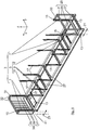
- the transport platform is implemented largely without a large-area closed sheet metal planking as an open support structure 3, which has a floor assembly 5 and vertical support 7.
- the floor pan 5 has in the Figure 1 two parallel lateral longitudinal beams 9, which extend in the longitudinal direction of the platform x and, together with frontal transverse beams 11, form a closed support frame.
- the longitudinal and transverse beams 9, 11 are exemplarily designed as I-steel profile parts in the figures, but are not limited to such an I-profile.
- each of the four corner areas of the floor assembly 5 corner fittings 13 on the floor side are welded.
- each of the four corner areas of the floor pan 5 has the aforementioned vertical supports 7, which protrude upward in the platform vertical direction z and terminate on the top with upper corner fittings 15.
- the upper and lower corner fittings 13, 15 are designed as standardized ISO container corner fittings, with fastening eyes 16 ( Figure 5 or 6th ), in which the closure elements 61 described later can engage.
- the distances between the upper and lower corner fittings 13, 15 are essentially identical to the standardized distances between ISO container corner fittings in an ISO container.
- the distances between the upper and lower corner fittings 13, 15 in the platform longitudinal direction x and in the The longitudinal direction of the platform y as well as the vertical direction of the platform z each simulates the corresponding distances between container corner fittings in a 40-foot ISO container.
- stanchions 17 are attached to each of the two lateral longitudinal members 9, their connection to the longitudinal members 9 later based on the Figures 2 and 3 is explained.
- the support structure 3 of the transport platform is specially designed for loading onto a truck semitrailer 19, the chassis of which is in the Figure 8 is partially indicated. When loaded, it is in the Figure 1
- the left side of the transport platform faces the truck driver's cab and the right side of the transport platform is positioned on the rear of the semitrailer.
- the transport platform viewed in the longitudinal direction x of the platform, is extended on the front side beyond the corner fittings 13 on the floor with a rear overhang 21 and with an overhang 23 on the driver's cab side.
- the two protrusions 21, 23 are open on the top so as not to interfere with the loading process from above.
- the two side longitudinal members 9 extend continuously over the corner fittings 13 on the bottom and close them off at a closed vertical frame 25.
- the circumferentially closed vertical frame 25 is made up of a bottom cross strut 27 which runs between the two longitudinal members 9 and vertical struts 29 which converge with an upper cross strut 31 at the upper frame corners.
- the two upper frame corners of the vertical frame 25 are connected to the upper corner fittings 15 of the vertical girders 7 via longitudinal struts 33 in order to increase the platform stability, especially in the rear area.
- the rear-side vertical supports 7 therefore together with the rear-side closed vertical frame 25 form a stable open support structure, by means of which the rear side of the transport platform is stiffened in a weight-saving manner.
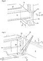
- the overhang 23 on the driver's cab side protruding forward is closed box-shaped with sheet metal planking 34 which is delimited by vertical, longitudinal and transverse struts 32 ( Figure 1 or 6th ).
- the sheet metal planking 34 has an end face 35 facing the truck driver's cab, which is connected to the front end-side cross member 11 via a bottom wall 37 and is connected to the front vertical members 7 of the transport platform via side walls 39.
- the overhang 23 on the driver's cab side is constructed in such a way that there is sufficient clearance for the adjacent components of the truck driver's cab and the truck semitrailer 19, for example during a steering process. Accordingly, the bottom wall 37 of the overhang 23 on the driver's cab side is formed with a height offset ⁇ z ( Figure 5 ) from the underside of the platform.
- ⁇ z Figure 5
- the transport platform has a centering plate part 43 on its front underside, which forms a center tunnel that is open at the bottom and has a centering surface 45 set back upwards in the vertical direction z of the platform ( Figure 5 ) is formed, which in the platform transverse direction y outwards in lateral run-up bevels 47 ( Figure 5 ) skip.
- the centering plate part 43 is welded in the longitudinal direction x of the platform at the front to the front cross member 11 and at the rear to a bottom Cross brace 27 welded.
- the centering plate part 43 acts with a corresponding counter profile 49 ( Figure 8 ) together on the truck semitrailer 19 in order to ensure that the transport platform is correctly positioned on the truck semitrailer 19.
- the counter profile 49 of the truck semitrailer 19 is in the Figure 8 formed from two semi-trailer longitudinal members 63 bent upwards.
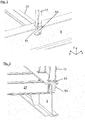
- the plug-in system with which the stanchions 17 are detachably mounted on the longitudinal members 9 is shown in detail views.
- the plug-in system has a stake pocket 53 which is inserted into a material recess 51 in the side member and welded to it.
- the lower wedge-shaped end of the stanchion 17 can be positively inserted into the stanchion pocket 53, which is likewise wedge-shaped. If necessary, the stanchion 17 can be secured in the stake pocket 53 by means of securing means (not shown).
- two laterally opposite stanchions 17 are arranged in alignment in a transverse plane yz in the platform transverse direction y.
- a transverse strut 27 runs in each transverse plane yz, which is connected to the stanchion connection points of the side longitudinal members 9.
- the cuboid lower corner fitting 13 is welded into a further material cutout 55 of the longitudinal member 9 and the cross member 11.
- the lower corner fitting 13 is arranged in alignment with the rear vertical support 7, viewed in the platform vertical direction z.
- a U-profile-shaped reinforcing sheet metal part 57 is supported between the corner fitting 13 on the bottom and the upper T-flange of the longitudinal member 9.
- Corresponding reinforcing sheet metal parts 57 are also installed on the further corner fittings 13 on the bottom.
- FIG 7 a transport platform partially equipped with round timbers 1 is shown, which is loaded on the semi-trailer 19. From the semi-trailer 19 is in the Figures 7 and 8th only the chassis shown.
- locking elements 61 on the chassis for example twist locks, are in engagement with the lower ISO corner fittings 13 of the transport platform and are locked with them.
- tensioning straps (not shown) can be used in current practice in order to clamp the logs 1 tightly on the transport platform.
- the tensioning belt retractors required for this can be provided loosely in a first embodiment variant or, in a preferred second embodiment variant, can be securely fastened to the transport platform as permanently mounted add-on parts.
- FIG 8 a loading process of the empty transport platform is illustrated. Accordingly, the transport platform is lowered onto the chassis of the truck semitrailer 19 by means of an only roughly indicated gripper 63 of a container forklift truck.
- the gripper 63 is in engagement with the four upper ISO corner fittings 15 of the transport platform and locked with them by actuating locking elements (for example twist locks).
- locking elements for example twist locks.
- the transport platform is lifted using the container forklift placed in the correct position on the chassis of the semi-trailer 19, whereby the chassis-side locking elements 61 come into engagement with the lower ISO corner fittings 13 of the transport platform and are locked with them.
- the semi-trailer chassis shown is of a so-called gooseneck design, in which the semi-trailer longitudinal members 63 are cranked upwards by a height offset z and form the counter profile 49, interacts with the centering plate part 43 of the transport platform.
Landscapes
- Engineering & Computer Science (AREA)
- Mechanical Engineering (AREA)
- Transportation (AREA)
- Health & Medical Sciences (AREA)
- Public Health (AREA)
- Body Structure For Vehicles (AREA)
- Auxiliary Methods And Devices For Loading And Unloading (AREA)
- Pallets (AREA)
- Packaging Of Machine Parts And Wound Products (AREA)
Description
Die Erfindung betrifft eine Transportplattform zum Verladen, Befördern und Lagern von langgestrecktem, abgelängtem Ladegut, insbesondere Rundholz, nach dem Oberbegriff des Patentanspruches 1.The invention relates to a transport platform for loading, conveying and storing elongated, cut-to-length cargo, in particular round wood, according to the preamble of claim 1.
Rundhölzer bzw. Baumstämme werden beim Transport in gängiger Praxis einzeln zwischen unterschiedlichen Verkehrsträgern verladen. Beispielhaft wird das Rundholz an einem Verladebahnhof zwischen der Bahn und einem LKW-Auflieger einzeln umgeladen, und zwar meist mit einem am LKW angebauten Kran. Der komplette Umladevorgang ist daher mit sehr langen Umschlagzeiten und damit auch mit hohen Personalkosten verbunden. Zudem muss am LKW ein Ladekran angebaut sein, um den Ladevorgang durchzuführen.In common practice, round timber or tree trunks are loaded individually between different modes of transport. For example, the logs are reloaded individually at a loading station between the railway and a truck trailer, mostly with a crane attached to the truck. The complete reloading process is therefore associated with very long handling times and thus also with high personnel costs. In addition, a loading crane must be attached to the truck in order to carry out the loading process.
Allgemein bekannt ist auch der Einsatz von genormten ISO-Containern aus Stahl, mit deren Hilfe ein einfaches und schnelles Verladen, Befördern, Lagern und Entladen unterschiedlicher Ladegüter ermöglicht ist. Die ISO-Container können beispielhaft als 20-Fuß-Container oder als 40-Fuß-Container bereitgestellt sein. Ein solcher ISO-Container kann vollständig oder teilweise geschlossen ausgeführt sein, und zwar mit Stirn-, Boden-, Deck- und/oder Seitenwänden. Der ISO-Container weist zudem an seinen acht Außenecken ebenfalls normierte ISO-Eckbeschläge (sogenannte Containerecken) auf, mit deren Hilfe der ISO-Container in einfacher und schneller Weise mit zum Beispiel einer Aufliegerkontur eines LKW-Sattelaufliegers oder anderer Verkehrsträger verriegelbar ist sowie der ISO-Container in mehreren Container-Lagen übereinander stapelbar ist.The use of standardized ISO containers made of steel is also well known, with the help of which a simple and fast loading, transport, storage and unloading of different cargo is made possible. The ISO containers can be provided, for example, as 20-foot containers or as 40-foot containers. Such an ISO container can be completely or partially closed, with front, bottom, top and / or side walls. The ISO container also has standardized ISO corner fittings (so-called container corners) at its eight outer corners, with the help of which the ISO container can be easily and quickly fitted with, for example, a trailer contour of a truck semitrailer or other Transport carrier can be locked and the ISO container can be stacked in several container layers on top of one another.
Aus der
Die Aufgabe der Erfindung besteht darin, eine Transportplattform bereitzustellen, die speziell für den Transport von langgestrecktem, abgelängtem Ladegut, insbesondere Rundholz, geeignet ist und mittels der die Umschlagzeiten beim Verladen des Ladeguts zwischen unterschiedlichen Verkehrsträgern reduzierbar ist.The object of the invention is to provide a transport platform which is especially suitable for the transport of elongated, cut-to-length cargo, in particular round wood, and by means of which the handling times when loading the cargo between different modes of transport can be reduced.
Die Aufgabe ist durch die Merkmale des Patentanspruches 1 gelöst. Bevorzugte Weiterbildungen der Erfindung sind in den abhängigen Ansprüchen offenbart.The object is achieved by the features of claim 1. Preferred developments of the invention are disclosed in the dependent claims.
Erfindungsgemäß werden die Rundhölzer zum Beispiel am Verladebahnhof nicht mehr einzeln zwischen dem LKW-Auflieger und den Bahn-Aufliegern umgeladen. Anstelle dessen wird eine Transportplattform bereitgestellt, die speziell für ein einfaches und schnelles Verladen, Befördern, Lagern und Entladen solcher Rundhölzer (oder allgemein langgestreckter abgelängter Ladegüter) ausgelegt ist. Die Transportplattform ist als eine offene Trägerkonstruktion mit einer Bodengruppe realisiert, die aus Längs- und Querträgern aufgebaut ist. An jedem der vier Eckbereiche der Bodengruppe ist ein bodenseitiger Eckbeschlag vorgesehen, mit dem die Transportplattform an einer Aufliegerkontur, etwa eines LKW-Sattelaufliegers oder eines anderen Verkehrsträgers, verriegelbar ist. Zudem weist die Bodengruppe an jedem ihrer vier Eckbereiche einen Vertikalträger auf, der mit einem oberseitigen Eckbeschlag abschließt. Auf diese Weise ist gewährleistet, dass die Transportplattform in mehreren Lagen übereinander gestapelt werden kann. Mittels der oberen Eckbeschläge kann eine auf der Transportplattform gestapelte weitere Transportplattform verriegelt werden. Alternativ dazu kann in die oberen Eckbeschläge ein Containerstapler eingreifen, um die Transportplattform zu verladen. Derartige Containerstapler werden in gängiger Praxis beim Verladen von ISO-Containern genutzt und sind zum Beispiel an Verladebahnhöfen im Einsatz.According to the invention, the logs are no longer reloaded individually between the truck trailer and the rail trailer, for example at the loading station. Instead, a transport platform is provided that is specially designed for easy and quick loading, transport, storage and unloading of such round timber (or generally elongated, cut-to-length cargo). The transport platform is implemented as an open support structure with a floor assembly made up of longitudinal and transverse supports. At each of the four corner areas of the floor assembly, a floor-side corner fitting is provided, with which the transport platform can be locked to a trailer contour, for example a truck semitrailer or another mode of transport. In addition, the floor assembly has a vertical support at each of its four corner areas, which is connected to an upper side Complete the corner fitting. This ensures that the transport platform can be stacked in several layers on top of one another. Another transport platform stacked on the transport platform can be locked by means of the upper corner fittings. Alternatively, a container forklift can reach into the upper corner fittings to load the transport platform. Such container forklifts are commonly used when loading ISO containers and are used, for example, at loading stations.
Auf diese Weise kann die Transportplattform nach Art eines ISO-Containers in einfacher Weise zwischen unterschiedlichen Verkehrsträger, zum Beispiel zwischen der Bahn und einem LKW-Sattelauflieger umgeladen werden, und zwar mittels eines Containerstaplers zum Umladen von ISO-Containern. Die Rundhölzer müssen daher nicht mehr von einem LKW-Kran umgeladen werden, wodurch beim Verladevorgang eine massive Zeitersparnis erzielt wird.In this way, the transport platform in the manner of an ISO container can be reloaded in a simple manner between different modes of transport, for example between the train and a truck semitrailer, using a container forklift truck for reloading ISO containers. The logs therefore no longer have to be reloaded by a truck crane, which results in massive time savings during the loading process.
Bevorzugt ist es, wenn die oberen und unteren Eckbeschläge als ISO-Containereckbeschläge ausgeführt sind, wie sie in einem ISO-Container verbaut sind. Die Abstände der oberen und unteren Eckbeschläge können zudem im Wesentlichen identisch zu den Abständen der im ISO-Container verbauten ISO-Containereckbeschläge sein.It is preferred if the upper and lower corner fittings are designed as ISO container corner fittings, as they are installed in an ISO container. The distances between the upper and lower corner fittings can also be essentially identical to the distances between the ISO container corner fittings installed in the ISO container.
In einer technischen Umsetzung kann die Bodengruppe der Transportplattform zwei zueinander parallele seitliche Längsträger aufweisen. Diese können unter Bildung eines geschlossenen Tragrahmens zumindest über stirnseitige Querträger miteinander verbunden sein. Die so gebildete Bodengruppe ist bevorzugt als eine offene Stahl-Trägerkonstruktion gestaltet, das heißt ohne Blech-Beplankung zwischen den Quer- und Längsträgern.In a technical implementation, the floor assembly of the transport platform can have two side longitudinal members that are parallel to one another. These can be connected to one another at least via end-face cross members, forming a closed support frame. The floor assembly formed in this way is preferably designed as an open steel support structure, that is to say without sheet metal planking between the transverse and longitudinal supports.
Zur seitlichen Transportsicherung der Rundhölzer ist es bevorzugt, wenn die Bodengruppe beidseitig Rungen aufweisen. Die Rungen sind jeweils an Anbindungspunkten der Bodengruppe, das heißt an den beiden Längsträgern fest oder lösbar angebunden. Bevorzugt ist ein lösbares Stecksystem, bei dem die Runge in eine am Längsträger positionierte Rungentasche lösbar einsteckbar ist. Auf diese Weise kann die Runge zu Reparaturzwecken einfach ausgetauscht werden.To secure the logs from the side during transport, it is preferred if the floor assembly has stanchions on both sides. The stanchions are each connected to the connection points of the floor pan, that is to say to the two side members, in a fixed or detachable manner. A releasable plug-in system is preferred, in which the stanchion can be releasably inserted into a stake pocket positioned on the side member. In this way, the stanchion can easily be replaced for repair purposes.
Die Plattform-Stabilität kann gesteigert werden, wenn die Rungen in der Plattform-Querrichtung in Flucht gegenüberliegen. Zudem können die beiden Längsträger an den Rungen-Anbindungspunkten jeweils über Querstreben miteinander verbunden sein. Die Querstreben sowie die Rungen laufen somit an den Rungen-Anbindungspunkten der Längsträger zu einer Knotenstelle zusammen, über die Kräfte in die Trägerkonstruktion eingeleitet werden können.The platform stability can be increased if the stanchions are aligned in the transverse direction of the platform. In addition, the two side members can be connected to each other at the stanchion connection points via cross struts. The cross struts and the stanchions thus converge at the stanchion connection points of the longitudinal girders to form a node, via which forces can be introduced into the girder structure.
Um das von der Transportplattform verfügbare Ladevolumen zu vergrößern, ist die Transportplattform in der Plattform-Längsrichtung über die bodenseitigen Eckbeschläge hinaus mit zumindest einem Überstand verlängert. Der Überstand ist bei einer auf einem LKW-Sattelauflieger verladenen Transportplattform an der Sattelauflieger-Heckseite positioniert. Zur Realisierung des heckseitigen Überstands können die beiden seitlichen Längsträger über die bodenseitigen hinteren Eckbeschläge hinaus verlängert sein und mit einem geschlossenen Vertikalrahmen abschließen. Der heckseitige Vertikalrahmen kann aus einer bodenseitigen Querstrebe, die die beiden Längsträger miteinander verbindet, sowie aus Vertikalstreben aufgebaut sein, die jeweils am Längsträger verschweißt sind und oberseitig mit einer oberen Querstrebe verbunden sind. Die obere Querstrebe sowie die Vertikalstreben des Vertikalrahmens laufen an oberen Rahmenecken zusammen. Die beiden oberen Rahmenecken können zur weiteren Steigerung der Plattform-Stabilität über Längsstreben mit den oberen Eckbeschlägen der hinteren Vertikalträger verbunden sein. In Hinblick auf eine Reduzierung des Plattform-Gewichts kann der heckseitige Überstand als eine offene Tragkonstruktion ausgeführt sein, das heißt komplett ohne Blech-Beplankung.In order to increase the loading volume available from the transport platform, the transport platform is extended in the longitudinal direction of the platform beyond the corner fittings on the bottom with at least one overhang. In the case of a transport platform loaded on a truck semitrailer, the overhang is positioned on the rear of the semitrailer. To implement the rear overhang, the two side longitudinal members can be extended beyond the rear corner fittings on the floor and end with a closed vertical frame. The rear vertical frame can be constructed from a bottom cross strut that connects the two longitudinal members to one another, as well as from vertical struts which are each welded to the longitudinal member and are connected at the top to an upper cross member. The upper cross strut and the vertical struts of the vertical frame converge at the upper frame corners. The two upper frame corners can be used for further enhancement the platform stability must be connected to the upper corner fittings of the rear vertical beams via longitudinal struts. With a view to reducing the weight of the platform, the rear overhang can be designed as an open support structure, i.e. completely without sheet metal planking.
Zusätzlich weist die Transportplattform an der gegenüberliegenden Stirnseite einen weiteren Überstand auf. Dieser ragt in einem, auf dem LKW-Sattelauflieger verladenen Zustand in Richtung des LKW-Führerhauses vor. Der führerhausseitige Überstand ist unter Bildung eines bodenseitigen Freiraums mit einem Höhenversatz von der Plattform-Unterseite abgesetzt. Zudem ist der Überstand derart bemessen, dass daran angrenzende Komponenten des LKW-Führerhauses oder des LKW-Sattelaufliegers, zum Beispiel Hydraulikleitungen oder dergleichen, über einen ausreichend großen Freigang von der Transportplattform beabstandet sind.In addition, the transport platform has a further protrusion on the opposite end. In a state loaded on the truck semitrailer, this protrudes in the direction of the truck driver's cab. The overhang on the driver's cab side is offset from the underside of the platform with the formation of a free space on the floor side with a height offset. In addition, the overhang is dimensioned such that adjoining components of the truck driver's cab or the truck semitrailer, for example hydraulic lines or the like, are spaced apart from the transport platform over a sufficiently large clearance.
Der führerhausseitige Überstand kann in einer bevorzugten Ausführungsform eine kastenförmige Tragkonstruktion aus Quer- und Längsstreben sein, und zwar in Kombination mit einer Blech-Beplankung. Die Blech-Beplankung weist eine dem LKW-Führerhaus zugewandte Stirnwand auf, die über eine Bodenwand mit dem stirnseitigen Querträger der Transportplattform verbunden ist und über Seitenwände mit den Vertikalträgern der Transportplattform verbunden ist.In a preferred embodiment, the overhang on the driver's side can be a box-shaped support structure made of transverse and longitudinal struts, in combination with sheet metal planking. The sheet metal planking has an end wall facing the truck driver's cab, which is connected to the front cross member of the transport platform via a bottom wall and is connected to the vertical members of the transport platform via side walls.
Sowohl der führerhausseitige Überstand als auch der heckseitige Überstand kann nach oben offen, das heißt ohne Deckwand, ausgeführt sein, um den Ladevorgang nicht zu beinträchtigen.Both the overhang on the driver's cab side and the overhang on the rear can be designed to be open at the top, i.e. without a top wall, in order not to interfere with the loading process.
In einer Weiterbildung kann die Bodengruppe der Transportplattform unterseitig ein Zentrierprofil aufweisen, das beim Verladen der Transportplattform auf einem LKW-Sattelauflieger mit einem korrespondierenden Sattelauflieger-Gegenprofil in Formschluss bringbar ist, um eine lagerichtige Positionierung der Transportplattform auf dem LKW-Sattelauflieger zu gewährleisten.In a further development, the bottom group of the transport platform can have a centering profile on the underside, which when the transport platform is loaded onto a truck semitrailer with a Corresponding semi-trailer mating profile can be brought into a form fit in order to ensure correct positioning of the transport platform on the truck semi-trailer.
Das Zentrierprofil kann als ein Zentrierblechteil realisiert sein, das unter Bildung eines nach unten offenen Mitteltunnels eine in der Plattform-Hochrichtung nach oben zurückgesetzte Zentrierfläche aufweist, die in der Plattform-Querrichtung nach außen in Anlaufschrägen übergeht. Die damit korrespondierende Gegenkontur des LKW-Sattelaufliegers kann mittels nach oben abgekröpfter Führungsschienen eines sogenannten Gooseneck-Fahrgestells des Sattelaufliegers realisiert sein, über die das plattformseitige Zentrierblechteil bei lagerichtiger Absenkung der Transportplattform formschlüssig gestülpt wird. Das Zentrierblechteil ist bevorzugt in der Plattform-Längsrichtung vorne am führerhausseitigen Querträger und hinten an einer, die beiden Längsträger verbindenden Querstrebe angebunden.The centering profile can be implemented as a centering sheet metal part which, while forming a downwardly open central tunnel, has a centering surface set back upward in the vertical direction of the platform, which merges outwardly into bevels in the transverse direction of the platform. The corresponding counter-contour of the truck semitrailer can be implemented by means of upwardly bent guide rails of a so-called gooseneck chassis of the semitrailer, over which the platform-side centering plate part is slipped in a form-fitting manner when the transport platform is lowered in the correct position. The centering plate part is preferably connected in the longitudinal direction of the platform at the front to the cross member on the driver's cab side and to a cross strut connecting the two longitudinal members at the rear.
Zur Verriegelung von Transportplattformen untereinander und/oder mit einem Trägerfahrzeug sind Verschlusselemente (zum Beispiel Twistlocks) bekannt, mit deren Hilfe die Eckbeschläge in formschlüssiger Verbindung mit dem Trägerfahrzeug oder mit einer weiteren Transportplattform bringbar ist.For locking transport platforms with one another and / or with a carrier vehicle, locking elements (for example twistlocks) are known, with the aid of which the corner fittings can be brought into a form-fitting connection with the carrier vehicle or with another transport platform.
Die Erfindung und ihre vorteilhaften Aus- und Weiterbildungen sowie deren Vorteile werden nachfolgend anhand von Zeichnungen näher erläutert.The invention and its advantageous designs and developments as well as their advantages are explained in more detail below with reference to drawings.
Es zeigen:
- Figur 1
- in einer perspektivischen Ansicht die Transportplattform in Alleinstellung;
- Figur 2 bis 6
- jeweils Detailansichten der Transportplattform;
Figur 7- in einer perspektivischen Darstellung die auf einem Sattelauflieger verladene Transportplattform; und
- Figur 8
- eine Ansicht, in der ein Ladevorgang veranschaulicht ist, bei dem die Transportform auf einen Sattelauflieger verladen wird.
- Figure 1
- in a perspective view the transport platform in isolation;
- Figures 2 to 6
- each detailed view of the transport platform;
- Figure 7
- a perspective view of the transport platform loaded on a semi-trailer; and
- Figure 8
- a view in which a loading process is illustrated in which the form of transport is loaded onto a semi-trailer.
Anhand der
An jedem der vier Eckbereiche der Bodengruppe 5 sind jeweils bodenseitige Eckbeschläge 13 verschweißt. Zudem weist jeder der vier Eckbereiche der Bodengruppe 5 die bereits erwähnten Vertikalträger 7 auf, die in der Plattform-Hochrichtung z nach oben abragen und oberseitig mit oberen Eckbeschlägen 15 abschließen. Die oberen und unteren Eckbeschläge 13, 15 sind als genormte ISO-Containereckbeschläge ausgeführt, und zwar mit Befestigungsaugen 16 (
Um eine seitliche Transportsicherung der Rundhölzer 1 zu gewährleisten, sind an den beiden seitlichen Längsträgern 9 jeweils Rungen 17 befestigt, deren Anbindung an den Längsträgern 9 später anhand der
Die Trägerkonstruktion 3 der Transportplattform ist speziell für die Verladung auf einen LKW-Sattelauflieger 19 ausgelegt, dessen Fahrgestell in der
Zur Realisierung des heckseitigen Überstands 21 erstrecken sich die beiden seitlichen Längsträger 9 durchgängig über die bodenseitigen Eckbeschläge 13 hinweg und schließen diese an einem geschlossenen Vertikalrahmen 25 ab. Der umfangsseitig geschlossene Vertikalrahmen 25 ist aus einer bodenseitigen Querstrebe 27 aufgebaut, die zwischen den beiden Längsträgern 9 verläuft, sowie aus Vertikalstreben 29 aufgebaut, die an oberen Rahmenecken mit einer oberen Querstrebe 31 zusammenlaufen. Die beiden oberen Rahmenecken des Vertikalrahmens 25 sind über Längsstreben 33 mit den oberen Eckbeschlägen 15 der Vertikalträger 7 verbunden, um die Plattform-Stabilität speziell im Heckbereich zu erhöhen. Die heckseitigen Vertikalträger 7 bilden daher zusammen mit dem heckseitigen geschlossenen Vertikalrahmen 25 eine stabile offene Tragkonstruktion, mittels der die Heckseite der Transportplattform gewichtsgünstig ausgesteift ist.To implement the
Der nach vorne abragende führerhausseitige Überstand 23 ist im Gegensatz zu der offenen Tragkonstruktion des heckseitigen Überstands 21 kastenförmig geschlossen mit einer Blech-Beplankung 34 ausgebildet, die mit Vertikal-, Längs- und Querstreben 32 begrenzt ist (
Der führerhausseitige Überstand 23 ist derart konstruiert, dass für die angrenzenden Komponenten des LKW-Führerhauses und des LKW-Sattelaufliegers 19 ein ausreichender Freigang zum Beispiel bei einem Lenkvorgang vorhanden ist. Demgemäß ist die Bodenwand 37 des führerhausseitigen Überstands 23 unter Bildung eines bodenseitigen Freiraums 41 mit einem Höhenversatz Δz (
Wie aus der
In der
Zur Steigerung der Plattform-Stabilität sind jeweils in einer Querebene yz zwei seitlich gegenüberliegende Rungen 17 in der Plattform-Querrichtung y in Flucht angeordnet. Zudem verläuft in jeder Querebene yz eine Querstrebe 27, die jeweils an den Rungen-Anbindungspunkten der seitlichen Längsträgern 9 angebunden ist.To increase the platform stability, two laterally opposite
In der
Wie aus der
In der
In der
- 11
- RundhölzerRound timber
- 33rd
- TrägerkonstruktionSupport structure
- 55
- BodengruppeFloor pan
- 77th
- VertikalträgerVertical beam
- 99
- LängsträgerSide member
- 1111
- QuerträgerCross member
- 1313th
- untere Eckbeschlägelower corner fittings
- 1515th
- obere Eckbeschlägeupper corner fittings
- 1616
- BefestigungsaugenFastening eyes
- 1717th
- RungenStanchions
- 1919th
- SattelaufliegerSemi-trailers
- 2121
- heckseitiger Überstandrear overhang
- 2323
- führerhausseitiger ÜberstandOverhang on the driver's side
- 2525th
- VertikalrahmenVertical frame
- 2727
- bodenseitige Querstrebebottom cross brace
- 2929
- VertikalstrebeVertical strut
- 3131
- obere Querstrebeupper cross brace
- 3232
- Längs-, Quer- und VertikalstrebenLongitudinal, transverse and vertical struts
- 3333
- LängsstrebeLongitudinal strut
- 3434
- Blech-BeplankungSheet metal planking
- 3535
- StirnwandFront wall
- 3737
- BodenwandBottom wall
- 3939
- Seitenwändeside walls
- 4141
- Freiraumfree space
- 4343
- ZentrierblechteilCentering plate part
- 4545
- ZentrierflächeCentering surface
- 4747
- AnlaufschrägenBevels
- 4949
- GegenprofilCounter profile
- 5151
- Material-AusnehmungMaterial recess
- 5353
- RungentascheStake pocket
- 5555
- Material-AusnehmungMaterial recess
- 5757
- VerstärkungsblechteilReinforcement sheet metal part
- 6161
- VerschlusselementeClosure elements
- 6363
- Sattelauflieger-LängsträgerSemi-trailer side members
- 6565
- Containerstapler-GreiferContainer handler grapple
Claims (10)
- Transport platform for loading, conveying and storing elongate cut-to-length loads, in particular timber logs, said transport platform being implemented as a beam construction (3) having a base assembly (5) which is constructed from longitudinal beams (9) and cross beams (11), wherein a base-proximal corner casting (13) by way of which the transport platform is able to be locked to a semitrailer contour of a truck semitrailer (19) or any other mode of transport is provided at each of the four corner regions of the base assembly (5), and wherein the base assembly (5) at each of the four corner regions has a vertical beam (7) which terminates by way of a corner casting (15) on the upper side to which a further transport platform stacked thereon is able to be locked, or in which a container stacker engages for loading the transport platform, characterized in that the transport platform in the platform longitudinal direction (x) by way of at least one rearward protrusion (21) is extended beyond the base-proximal corner castings (13); in that the rearward protrusion (21) in the case of a transport platform loaded on the truck semitrailer (19) is disposed on the rear side of the semitrailer; in that the transport platform has a cab-proximal protrusion (23) which in a state loaded on the truck semitrailer (19) protrudes in the direction of a truck cab; and in that the cab-proximal protrusion (23), while forming a base-proximal void (41), is offset from the platform lower side by a height offset (Δz) such that, when positioning the transport platform on the truck semitrailer (19), semitrailer components are disposed in the region of the base-proximal void (41).
- Transport platform according to Claim 1, characterized in that the upper corner castings (13) and lower corner castings (15) are embodied as ISO container corner castings, and in that the spacings of the upper corner castings (13) and lower corner castings (15) are embodied so as to be identical to the ISO corner castings of an ISO container.
- Transport platform according to Claim 1 or 2, characterized in that the base assembly (5) has two mutually parallel lateral longitudinal beams (9) which, while forming a closed support frame, are connected to one another at least by cross beams (11) on the end sides.
- Transport platform according to Claim 1, 2, or 3, characterized in that the base assembly (5) for securing the load (1) during transport has stanchions (17) on both sides, and in that the stanchions (17) are fixedly or releasably attached to attachment points of the base assembly (5).
- Transport platform according to Claim 4, characterized in that the stanchions (17) in the platform transverse direction (y) lie opposite one another in mutual alignment, and in that the two longitudinal beams (9) are connected to one another by cross braces at the attachment points of mutually opposite stanchions (17).
- Transport platform according to one of the preceding claims, characterized in that, for implementing the protrusion (21), the two lateral longitudinal beams (9) are extended beyond the base-proximal corner castings (13) and terminate at a closed vertical frame (25), and in that the vertical frame (25) is constructed from a base-proximal cross brace (27), an upper cross brace (31) as well as from vertical braces (29) which converge at upper frame corners, and in that the two upper frame corners by way of longitudinal braces (33) are connected to the upper corner castings (15) of the vertical beams (7).
- Transport platform according to one of the preceding claims, characterized in that the cab-proximal protrusion (23) is closed in the manner of a box, specifically by sheet metal panelwork (34) which has an end wall (35) which faces the cab and by way of a base wall (37) is connected to the cross beams (11) on te end sides, and by way of lateral walls (39) is connected to the vertical beams (7).
- Transport platform according to one of the preceding claims, characterized in that the base assembly (5) on the lower side has a centring profile (43) which when loading the transport platform onto a truck semitrailer (19) can be brought to connect in a form-fitting manner to a corresponding mating profile (49) so as to guarantee positioning of the transport platform in the correct orientation on the truck semitrailer (19).
- Transport platform according to Claim 8, characterized in that the centring profile (43) is implemented as a sheet metal centring part which in the platform height direction (z) has an upwardly recessed profiled face (45) which in the platform transverse direction (y) transitions toward the outside into ramps (47).
- Transport platform according to Claim 9, characterized in that the sheet metal centring part (43) in the platform longitudinal direction (x) is attached to the cab-proximal cross beam (11) and to a cross brace (27) that connects the two longitudinal beams (9).
Priority Applications (1)
| Application Number | Priority Date | Filing Date | Title |
|---|---|---|---|
| PL17811230T PL3548332T3 (en) | 2016-11-30 | 2017-11-23 | Transport platform |
Applications Claiming Priority (2)
| Application Number | Priority Date | Filing Date | Title |
|---|---|---|---|
| DE102016014249.9A DE102016014249B4 (en) | 2016-11-30 | 2016-11-30 | transport platform |
| PCT/EP2017/080222 WO2018099800A1 (en) | 2016-11-30 | 2017-11-23 | Transport platform |
Publications (2)
| Publication Number | Publication Date |
|---|---|
| EP3548332A1 EP3548332A1 (en) | 2019-10-09 |
| EP3548332B1 true EP3548332B1 (en) | 2021-09-15 |
Family
ID=60627595
Family Applications (1)
| Application Number | Title | Priority Date | Filing Date |
|---|---|---|---|
| EP17811230.6A Active EP3548332B1 (en) | 2016-11-30 | 2017-11-23 | Transport platform |
Country Status (7)
| Country | Link |
|---|---|
| US (1) | US11214436B2 (en) |
| EP (1) | EP3548332B1 (en) |
| CN (1) | CN110139779B (en) |
| DE (1) | DE102016014249B4 (en) |
| HU (1) | HUE057360T2 (en) |
| PL (1) | PL3548332T3 (en) |
| WO (1) | WO2018099800A1 (en) |
Families Citing this family (1)
| Publication number | Priority date | Publication date | Assignee | Title |
|---|---|---|---|---|
| US10807510B2 (en) * | 2018-09-25 | 2020-10-20 | Brambo Services | Device for loading and unloading goods |
Family Cites Families (19)
| Publication number | Priority date | Publication date | Assignee | Title |
|---|---|---|---|---|
| US3768686A (en) * | 1971-09-27 | 1973-10-30 | Matson Navigation Co | Container for elongated articles |
| DE9205852U1 (en) | 1992-05-05 | 1992-09-10 | Mec Marine Equipment + Consulting Behr & Horstmann Gmbh, 2102 Hamburg, De | |
| US5449081A (en) * | 1993-05-21 | 1995-09-12 | Stoughton Composites, Inc. | Modular insulated intermodal container construction |
| CA2115319A1 (en) * | 1993-10-25 | 1995-04-26 | Gary L. Fenton | Intermodal container |
| DE4338158A1 (en) * | 1993-11-02 | 1995-05-04 | Cts Eurocon Gmbh | Large-capacity transporting container |
| DE19503557C2 (en) | 1995-02-03 | 1997-04-10 | Waggonfabrik Talbot Gmbh & Co | Container system, in particular for luggage transportation |
| US5688086A (en) * | 1996-02-16 | 1997-11-18 | Aluminum Company Of America | Standard corner fittings for aluminum container frames |
| GB9722789D0 (en) | 1997-10-29 | 1997-12-24 | Clive Smith Martin | (Log) Cargo container |
| DE19833872A1 (en) | 1998-07-28 | 1999-07-08 | Harald Dienst | Chassis with stacking, changing and tilting container for loading on truck for transporting friable goods for processing |
| US6499922B2 (en) * | 2001-04-11 | 2002-12-31 | Terry Coray | Log divider |
| AT7105U1 (en) | 2003-07-15 | 2004-10-25 | Ahrenkiel Consulting Services | METHOD FOR UNLOADING A TRANSPORT VEHICLE FROM CONTAINERS OR. TO LOAD THE SAME |
| CN1781827A (en) | 2004-12-01 | 2006-06-07 | 中国国际海运集装箱(集团)股份有限公司 | Semitrailer chassis transport container |
| CN101323323A (en) * | 2007-06-13 | 2008-12-17 | 中国国际海运集装箱(集团)股份有限公司 | Conveyer of box type semi-trailer box |
| FR2919545B1 (en) * | 2007-08-03 | 2010-02-26 | Christophe Gaussin | MODULAR VEHICLE FOR HEAVY TRANSPORT, IN PARTICULAR A PORT |
| US8353647B2 (en) * | 2010-09-29 | 2013-01-15 | Raildecks (2009), Inc. | Collapsible intermodal transport platform |
| CN104837725B (en) * | 2012-12-12 | 2018-11-30 | 欧申奈克斯公司 | flat bracket |
| CN204433466U (en) * | 2015-02-04 | 2015-07-01 | 中集车辆(集团)有限公司 | Transportation frame |
| CN104890563A (en) * | 2015-05-27 | 2015-09-09 | 苏州大方特种车股份有限公司 | Log frame transport cart |
| US9545874B1 (en) * | 2015-07-28 | 2017-01-17 | Whitsell Manufacturing, Inc. | Bundling and transporting elongated articles |
-
2016
- 2016-11-30 DE DE102016014249.9A patent/DE102016014249B4/en not_active Expired - Fee Related
-
2017
- 2017-11-23 US US16/465,337 patent/US11214436B2/en active Active
- 2017-11-23 EP EP17811230.6A patent/EP3548332B1/en active Active
- 2017-11-23 PL PL17811230T patent/PL3548332T3/en unknown
- 2017-11-23 CN CN201780073881.1A patent/CN110139779B/en active Active
- 2017-11-23 HU HUE17811230A patent/HUE057360T2/en unknown
- 2017-11-23 WO PCT/EP2017/080222 patent/WO2018099800A1/en unknown
Also Published As
| Publication number | Publication date |
|---|---|
| CN110139779A (en) | 2019-08-16 |
| PL3548332T3 (en) | 2022-01-31 |
| DE102016014249A1 (en) | 2018-05-30 |
| CN110139779B (en) | 2022-07-19 |
| US20190389651A1 (en) | 2019-12-26 |
| US11214436B2 (en) | 2022-01-04 |
| HUE057360T2 (en) | 2022-05-28 |
| WO2018099800A1 (en) | 2018-06-07 |
| EP3548332A1 (en) | 2019-10-09 |
| DE102016014249B4 (en) | 2018-09-27 |
Similar Documents
| Publication | Publication Date | Title |
|---|---|---|
| EP1728729B1 (en) | Procedure to transport round timber or sawn timber | |
| EP3148890B1 (en) | Auxiliary transport device for pallets | |
| DE1961854A1 (en) | Semi truck | |
| EP1303447B1 (en) | Device for handling unit loads | |
| EP3548332B1 (en) | Transport platform | |
| EP3699058A1 (en) | Assembly of a rail vehicle and carrying device | |
| DE102016007415B3 (en) | Stem in a chassis of a freight car and method for the assembly of a stem | |
| EP3802365B1 (en) | Tank container arrangement | |
| EP3552992B1 (en) | Transport platform | |
| EP2546162A1 (en) | Palette for transporting round or trimmed timber | |
| DE202015104256U1 (en) | leveler | |
| DE10312638A1 (en) | Arrangement for securing coil in coil trough in loading floor of transport vehicle has thrust beam transversely above coil trough for attachment to different longitudinal positions of coil trough | |
| DE102017103836B4 (en) | Trailer frame and trailer | |
| EP3296175B1 (en) | Method for transporting a semitrailer | |
| DE2447576A1 (en) | Goods trucks loading platform - with attachments fitting over buffers of adjoining goods trucks | |
| DE102013000637A1 (en) | Body structure for vehicle, has connecting flange of flange connection, which is provided for forming joint location, at which covering part is attached, where covering part has edge web that is overlapped with connecting flange | |
| EP0334047B1 (en) | Case for tank container | |
| EP3699057B1 (en) | Liftable carrying device | |
| DE3115362A1 (en) | RUNGE FOR GOODS VEHICLES AND TRUCKS | |
| DE19618600C2 (en) | Openable side wall system for open freight cars | |
| DE2052164A1 (en) | Frameless freight container or trailer structure | |
| DE202008012966U1 (en) | Structure for a transport vehicle and provided with such a structure semitrailer | |
| EP0484708A2 (en) | Loading unit | |
| EP3009298A2 (en) | System for variable loading of a vehicle | |
| DE102014014667A1 (en) | Transport auxiliary device and method for its use |
Legal Events
| Date | Code | Title | Description |
|---|---|---|---|
| STAA | Information on the status of an ep patent application or granted ep patent |
Free format text: STATUS: UNKNOWN |
|
| STAA | Information on the status of an ep patent application or granted ep patent |
Free format text: STATUS: THE INTERNATIONAL PUBLICATION HAS BEEN MADE |
|
| PUAI | Public reference made under article 153(3) epc to a published international application that has entered the european phase |
Free format text: ORIGINAL CODE: 0009012 |
|
| STAA | Information on the status of an ep patent application or granted ep patent |
Free format text: STATUS: REQUEST FOR EXAMINATION WAS MADE |
|
| 17P | Request for examination filed |
Effective date: 20190612 |
|
| AK | Designated contracting states |
Kind code of ref document: A1 Designated state(s): AL AT BE BG CH CY CZ DE DK EE ES FI FR GB GR HR HU IE IS IT LI LT LU LV MC MK MT NL NO PL PT RO RS SE SI SK SM TR |
|
| AX | Request for extension of the european patent |
Extension state: BA ME |
|
| DAV | Request for validation of the european patent (deleted) | ||
| DAX | Request for extension of the european patent (deleted) | ||
| GRAP | Despatch of communication of intention to grant a patent |
Free format text: ORIGINAL CODE: EPIDOSNIGR1 |
|
| STAA | Information on the status of an ep patent application or granted ep patent |
Free format text: STATUS: GRANT OF PATENT IS INTENDED |
|
| INTG | Intention to grant announced |
Effective date: 20210416 |
|
| GRAS | Grant fee paid |
Free format text: ORIGINAL CODE: EPIDOSNIGR3 |
|
| GRAA | (expected) grant |
Free format text: ORIGINAL CODE: 0009210 |
|
| STAA | Information on the status of an ep patent application or granted ep patent |
Free format text: STATUS: THE PATENT HAS BEEN GRANTED |
|
| AK | Designated contracting states |
Kind code of ref document: B1 Designated state(s): AL AT BE BG CH CY CZ DE DK EE ES FI FR GB GR HR HU IE IS IT LI LT LU LV MC MK MT NL NO PL PT RO RS SE SI SK SM TR |
|
| REG | Reference to a national code |
Ref country code: CH Ref legal event code: EP |
|
| REG | Reference to a national code |
Ref country code: DE Ref legal event code: R096 Ref document number: 502017011533 Country of ref document: DE |
|
| REG | Reference to a national code |
Ref country code: IE Ref legal event code: FG4D Free format text: LANGUAGE OF EP DOCUMENT: GERMAN |
|
| REG | Reference to a national code |
Ref country code: AT Ref legal event code: REF Ref document number: 1430273 Country of ref document: AT Kind code of ref document: T Effective date: 20211015 |
|
| RAP4 | Party data changed (patent owner data changed or rights of a patent transferred) |
Owner name: ALLOG GMBH |
|
| REG | Reference to a national code |
Ref country code: LT Ref legal event code: MG9D |
|
| REG | Reference to a national code |
Ref country code: NL Ref legal event code: MP Effective date: 20210915 |
|
| PG25 | Lapsed in a contracting state [announced via postgrant information from national office to epo] |
Ref country code: BG Free format text: LAPSE BECAUSE OF FAILURE TO SUBMIT A TRANSLATION OF THE DESCRIPTION OR TO PAY THE FEE WITHIN THE PRESCRIBED TIME-LIMIT Effective date: 20211215 Ref country code: LT Free format text: LAPSE BECAUSE OF FAILURE TO SUBMIT A TRANSLATION OF THE DESCRIPTION OR TO PAY THE FEE WITHIN THE PRESCRIBED TIME-LIMIT Effective date: 20210915 Ref country code: NO Free format text: LAPSE BECAUSE OF FAILURE TO SUBMIT A TRANSLATION OF THE DESCRIPTION OR TO PAY THE FEE WITHIN THE PRESCRIBED TIME-LIMIT Effective date: 20211215 Ref country code: SE Free format text: LAPSE BECAUSE OF FAILURE TO SUBMIT A TRANSLATION OF THE DESCRIPTION OR TO PAY THE FEE WITHIN THE PRESCRIBED TIME-LIMIT Effective date: 20210915 Ref country code: RS Free format text: LAPSE BECAUSE OF FAILURE TO SUBMIT A TRANSLATION OF THE DESCRIPTION OR TO PAY THE FEE WITHIN THE PRESCRIBED TIME-LIMIT Effective date: 20210915 Ref country code: HR Free format text: LAPSE BECAUSE OF FAILURE TO SUBMIT A TRANSLATION OF THE DESCRIPTION OR TO PAY THE FEE WITHIN THE PRESCRIBED TIME-LIMIT Effective date: 20210915 Ref country code: FI Free format text: LAPSE BECAUSE OF FAILURE TO SUBMIT A TRANSLATION OF THE DESCRIPTION OR TO PAY THE FEE WITHIN THE PRESCRIBED TIME-LIMIT Effective date: 20210915 |
|
| PG25 | Lapsed in a contracting state [announced via postgrant information from national office to epo] |
Ref country code: LV Free format text: LAPSE BECAUSE OF FAILURE TO SUBMIT A TRANSLATION OF THE DESCRIPTION OR TO PAY THE FEE WITHIN THE PRESCRIBED TIME-LIMIT Effective date: 20210915 Ref country code: GR Free format text: LAPSE BECAUSE OF FAILURE TO SUBMIT A TRANSLATION OF THE DESCRIPTION OR TO PAY THE FEE WITHIN THE PRESCRIBED TIME-LIMIT Effective date: 20211216 |
|
| REG | Reference to a national code |
Ref country code: HU Ref legal event code: AG4A Ref document number: E057360 Country of ref document: HU |
|
| PG25 | Lapsed in a contracting state [announced via postgrant information from national office to epo] |
Ref country code: IS Free format text: LAPSE BECAUSE OF FAILURE TO SUBMIT A TRANSLATION OF THE DESCRIPTION OR TO PAY THE FEE WITHIN THE PRESCRIBED TIME-LIMIT Effective date: 20220115 Ref country code: SM Free format text: LAPSE BECAUSE OF FAILURE TO SUBMIT A TRANSLATION OF THE DESCRIPTION OR TO PAY THE FEE WITHIN THE PRESCRIBED TIME-LIMIT Effective date: 20210915 Ref country code: SK Free format text: LAPSE BECAUSE OF FAILURE TO SUBMIT A TRANSLATION OF THE DESCRIPTION OR TO PAY THE FEE WITHIN THE PRESCRIBED TIME-LIMIT Effective date: 20210915 Ref country code: PT Free format text: LAPSE BECAUSE OF FAILURE TO SUBMIT A TRANSLATION OF THE DESCRIPTION OR TO PAY THE FEE WITHIN THE PRESCRIBED TIME-LIMIT Effective date: 20220117 Ref country code: NL Free format text: LAPSE BECAUSE OF FAILURE TO SUBMIT A TRANSLATION OF THE DESCRIPTION OR TO PAY THE FEE WITHIN THE PRESCRIBED TIME-LIMIT Effective date: 20210915 Ref country code: ES Free format text: LAPSE BECAUSE OF FAILURE TO SUBMIT A TRANSLATION OF THE DESCRIPTION OR TO PAY THE FEE WITHIN THE PRESCRIBED TIME-LIMIT Effective date: 20210915 Ref country code: EE Free format text: LAPSE BECAUSE OF FAILURE TO SUBMIT A TRANSLATION OF THE DESCRIPTION OR TO PAY THE FEE WITHIN THE PRESCRIBED TIME-LIMIT Effective date: 20210915 Ref country code: AL Free format text: LAPSE BECAUSE OF FAILURE TO SUBMIT A TRANSLATION OF THE DESCRIPTION OR TO PAY THE FEE WITHIN THE PRESCRIBED TIME-LIMIT Effective date: 20210915 |
|
| REG | Reference to a national code |
Ref country code: DE Ref legal event code: R097 Ref document number: 502017011533 Country of ref document: DE |
|
| PG25 | Lapsed in a contracting state [announced via postgrant information from national office to epo] |
Ref country code: MC Free format text: LAPSE BECAUSE OF FAILURE TO SUBMIT A TRANSLATION OF THE DESCRIPTION OR TO PAY THE FEE WITHIN THE PRESCRIBED TIME-LIMIT Effective date: 20210915 |
|
| REG | Reference to a national code |
Ref country code: CH Ref legal event code: PL |
|
| PLBE | No opposition filed within time limit |
Free format text: ORIGINAL CODE: 0009261 |
|
| STAA | Information on the status of an ep patent application or granted ep patent |
Free format text: STATUS: NO OPPOSITION FILED WITHIN TIME LIMIT |
|
| PG25 | Lapsed in a contracting state [announced via postgrant information from national office to epo] |
Ref country code: LU Free format text: LAPSE BECAUSE OF NON-PAYMENT OF DUE FEES Effective date: 20211123 Ref country code: DK Free format text: LAPSE BECAUSE OF FAILURE TO SUBMIT A TRANSLATION OF THE DESCRIPTION OR TO PAY THE FEE WITHIN THE PRESCRIBED TIME-LIMIT Effective date: 20210915 Ref country code: BE Free format text: LAPSE BECAUSE OF NON-PAYMENT OF DUE FEES Effective date: 20211130 |
|
| REG | Reference to a national code |
Ref country code: BE Ref legal event code: MM Effective date: 20211130 |
|
| 26N | No opposition filed |
Effective date: 20220616 |
|
| GBPC | Gb: european patent ceased through non-payment of renewal fee |
Effective date: 20211215 |
|
| PG25 | Lapsed in a contracting state [announced via postgrant information from national office to epo] |
Ref country code: SI Free format text: LAPSE BECAUSE OF FAILURE TO SUBMIT A TRANSLATION OF THE DESCRIPTION OR TO PAY THE FEE WITHIN THE PRESCRIBED TIME-LIMIT Effective date: 20210915 |
|
| PG25 | Lapsed in a contracting state [announced via postgrant information from national office to epo] |
Ref country code: IE Free format text: LAPSE BECAUSE OF NON-PAYMENT OF DUE FEES Effective date: 20211123 Ref country code: GB Free format text: LAPSE BECAUSE OF NON-PAYMENT OF DUE FEES Effective date: 20211215 |
|
| PGFP | Annual fee paid to national office [announced via postgrant information from national office to epo] |
Ref country code: PL Payment date: 20221109 Year of fee payment: 6 |
|
| PG25 | Lapsed in a contracting state [announced via postgrant information from national office to epo] |
Ref country code: CY Free format text: LAPSE BECAUSE OF FAILURE TO SUBMIT A TRANSLATION OF THE DESCRIPTION OR TO PAY THE FEE WITHIN THE PRESCRIBED TIME-LIMIT Effective date: 20210915 |
|
| P01 | Opt-out of the competence of the unified patent court (upc) registered |
Effective date: 20230526 |
|
| PG25 | Lapsed in a contracting state [announced via postgrant information from national office to epo] |
Ref country code: LI Free format text: LAPSE BECAUSE OF NON-PAYMENT OF DUE FEES Effective date: 20220630 Ref country code: CH Free format text: LAPSE BECAUSE OF NON-PAYMENT OF DUE FEES Effective date: 20220630 |
|
| PGFP | Annual fee paid to national office [announced via postgrant information from national office to epo] |
Ref country code: RO Payment date: 20231123 Year of fee payment: 7 Ref country code: IT Payment date: 20231129 Year of fee payment: 7 Ref country code: HU Payment date: 20231108 Year of fee payment: 7 Ref country code: FR Payment date: 20231128 Year of fee payment: 7 Ref country code: DE Payment date: 20231128 Year of fee payment: 7 Ref country code: CZ Payment date: 20231107 Year of fee payment: 7 Ref country code: AT Payment date: 20231115 Year of fee payment: 7 |
|
| PGFP | Annual fee paid to national office [announced via postgrant information from national office to epo] |
Ref country code: PL Payment date: 20231106 Year of fee payment: 7 |