EP3547394A1 - Battery module, battery pack comprising same and battery module manufacturing method - Google Patents
Battery module, battery pack comprising same and battery module manufacturing method Download PDFInfo
- Publication number
- EP3547394A1 EP3547394A1 EP18806385.3A EP18806385A EP3547394A1 EP 3547394 A1 EP3547394 A1 EP 3547394A1 EP 18806385 A EP18806385 A EP 18806385A EP 3547394 A1 EP3547394 A1 EP 3547394A1
- Authority
- EP
- European Patent Office
- Prior art keywords
- bus bar
- battery module
- battery
- electrode
- electrode leads
- Prior art date
- Legal status (The legal status is an assumption and is not a legal conclusion. Google has not performed a legal analysis and makes no representation as to the accuracy of the status listed.)
- Granted
Links
- 238000004519 manufacturing process Methods 0.000 title claims description 13
- 238000003466 welding Methods 0.000 claims description 35
- 238000003825 pressing Methods 0.000 claims description 10
- 238000005452 bending Methods 0.000 description 9
- 238000000034 method Methods 0.000 description 9
- 238000010586 diagram Methods 0.000 description 8
- WHXSMMKQMYFTQS-UHFFFAOYSA-N Lithium Chemical compound [Li] WHXSMMKQMYFTQS-UHFFFAOYSA-N 0.000 description 6
- 229910052744 lithium Inorganic materials 0.000 description 6
- 230000000694 effects Effects 0.000 description 4
- 239000007773 negative electrode material Substances 0.000 description 4
- 239000007774 positive electrode material Substances 0.000 description 4
- 230000008878 coupling Effects 0.000 description 3
- 238000010168 coupling process Methods 0.000 description 3
- 238000005859 coupling reaction Methods 0.000 description 3
- 230000006870 function Effects 0.000 description 3
- HBBGRARXTFLTSG-UHFFFAOYSA-N Lithium ion Chemical compound [Li+] HBBGRARXTFLTSG-UHFFFAOYSA-N 0.000 description 2
- PXHVJJICTQNCMI-UHFFFAOYSA-N Nickel Chemical compound [Ni] PXHVJJICTQNCMI-UHFFFAOYSA-N 0.000 description 2
- 229910001416 lithium ion Inorganic materials 0.000 description 2
- 238000012986 modification Methods 0.000 description 2
- 230000004048 modification Effects 0.000 description 2
- 238000011084 recovery Methods 0.000 description 2
- RYGMFSIKBFXOCR-UHFFFAOYSA-N Copper Chemical compound [Cu] RYGMFSIKBFXOCR-UHFFFAOYSA-N 0.000 description 1
- 230000004308 accommodation Effects 0.000 description 1
- 229910052782 aluminium Inorganic materials 0.000 description 1
- XAGFODPZIPBFFR-UHFFFAOYSA-N aluminium Chemical compound [Al] XAGFODPZIPBFFR-UHFFFAOYSA-N 0.000 description 1
- OJIJEKBXJYRIBZ-UHFFFAOYSA-N cadmium nickel Chemical compound [Ni].[Cd] OJIJEKBXJYRIBZ-UHFFFAOYSA-N 0.000 description 1
- 239000003575 carbonaceous material Substances 0.000 description 1
- 239000004020 conductor Substances 0.000 description 1
- 229910052802 copper Inorganic materials 0.000 description 1
- 239000010949 copper Substances 0.000 description 1
- 238000007599 discharging Methods 0.000 description 1
- 238000001035 drying Methods 0.000 description 1
- 230000005611 electricity Effects 0.000 description 1
- 239000003792 electrolyte Substances 0.000 description 1
- 239000008151 electrolyte solution Substances 0.000 description 1
- 238000005516 engineering process Methods 0.000 description 1
- 239000011888 foil Substances 0.000 description 1
- GPRLSGONYQIRFK-UHFFFAOYSA-N hydron Chemical compound [H+] GPRLSGONYQIRFK-UHFFFAOYSA-N 0.000 description 1
- 238000001746 injection moulding Methods 0.000 description 1
- FUJCRWPEOMXPAD-UHFFFAOYSA-N lithium oxide Chemical compound [Li+].[Li+].[O-2] FUJCRWPEOMXPAD-UHFFFAOYSA-N 0.000 description 1
- 229910001947 lithium oxide Inorganic materials 0.000 description 1
- 239000000463 material Substances 0.000 description 1
- 230000003446 memory effect Effects 0.000 description 1
- 229910052751 metal Inorganic materials 0.000 description 1
- 239000002184 metal Substances 0.000 description 1
- 229910052759 nickel Inorganic materials 0.000 description 1
- 229920000642 polymer Polymers 0.000 description 1
- 239000000243 solution Substances 0.000 description 1
Images


Classifications
-
- H—ELECTRICITY
- H01—ELECTRIC ELEMENTS
- H01M—PROCESSES OR MEANS, e.g. BATTERIES, FOR THE DIRECT CONVERSION OF CHEMICAL ENERGY INTO ELECTRICAL ENERGY
- H01M50/00—Constructional details or processes of manufacture of the non-active parts of electrochemical cells other than fuel cells, e.g. hybrid cells
- H01M50/50—Current conducting connections for cells or batteries
- H01M50/543—Terminals
- H01M50/547—Terminals characterised by the disposition of the terminals on the cells
- H01M50/548—Terminals characterised by the disposition of the terminals on the cells on opposite sides of the cell
-
- H—ELECTRICITY
- H01—ELECTRIC ELEMENTS
- H01M—PROCESSES OR MEANS, e.g. BATTERIES, FOR THE DIRECT CONVERSION OF CHEMICAL ENERGY INTO ELECTRICAL ENERGY
- H01M50/00—Constructional details or processes of manufacture of the non-active parts of electrochemical cells other than fuel cells, e.g. hybrid cells
- H01M50/20—Mountings; Secondary casings or frames; Racks, modules or packs; Suspension devices; Shock absorbers; Transport or carrying devices; Holders
- H01M50/204—Racks, modules or packs for multiple batteries or multiple cells
-
- H—ELECTRICITY
- H01—ELECTRIC ELEMENTS
- H01M—PROCESSES OR MEANS, e.g. BATTERIES, FOR THE DIRECT CONVERSION OF CHEMICAL ENERGY INTO ELECTRICAL ENERGY
- H01M50/00—Constructional details or processes of manufacture of the non-active parts of electrochemical cells other than fuel cells, e.g. hybrid cells
- H01M50/50—Current conducting connections for cells or batteries
- H01M50/502—Interconnectors for connecting terminals of adjacent batteries; Interconnectors for connecting cells outside a battery casing
- H01M50/505—Interconnectors for connecting terminals of adjacent batteries; Interconnectors for connecting cells outside a battery casing comprising a single busbar
-
- H—ELECTRICITY
- H01—ELECTRIC ELEMENTS
- H01M—PROCESSES OR MEANS, e.g. BATTERIES, FOR THE DIRECT CONVERSION OF CHEMICAL ENERGY INTO ELECTRICAL ENERGY
- H01M50/00—Constructional details or processes of manufacture of the non-active parts of electrochemical cells other than fuel cells, e.g. hybrid cells
- H01M50/50—Current conducting connections for cells or batteries
- H01M50/502—Interconnectors for connecting terminals of adjacent batteries; Interconnectors for connecting cells outside a battery casing
- H01M50/509—Interconnectors for connecting terminals of adjacent batteries; Interconnectors for connecting cells outside a battery casing characterised by the type of connection, e.g. mixed connections
- H01M50/51—Connection only in series
-
- H—ELECTRICITY
- H01—ELECTRIC ELEMENTS
- H01M—PROCESSES OR MEANS, e.g. BATTERIES, FOR THE DIRECT CONVERSION OF CHEMICAL ENERGY INTO ELECTRICAL ENERGY
- H01M50/00—Constructional details or processes of manufacture of the non-active parts of electrochemical cells other than fuel cells, e.g. hybrid cells
- H01M50/50—Current conducting connections for cells or batteries
- H01M50/502—Interconnectors for connecting terminals of adjacent batteries; Interconnectors for connecting cells outside a battery casing
- H01M50/509—Interconnectors for connecting terminals of adjacent batteries; Interconnectors for connecting cells outside a battery casing characterised by the type of connection, e.g. mixed connections
- H01M50/512—Connection only in parallel
-
- H—ELECTRICITY
- H01—ELECTRIC ELEMENTS
- H01M—PROCESSES OR MEANS, e.g. BATTERIES, FOR THE DIRECT CONVERSION OF CHEMICAL ENERGY INTO ELECTRICAL ENERGY
- H01M50/00—Constructional details or processes of manufacture of the non-active parts of electrochemical cells other than fuel cells, e.g. hybrid cells
- H01M50/50—Current conducting connections for cells or batteries
- H01M50/502—Interconnectors for connecting terminals of adjacent batteries; Interconnectors for connecting cells outside a battery casing
- H01M50/514—Methods for interconnecting adjacent batteries or cells
- H01M50/516—Methods for interconnecting adjacent batteries or cells by welding, soldering or brazing
-
- H—ELECTRICITY
- H01—ELECTRIC ELEMENTS
- H01M—PROCESSES OR MEANS, e.g. BATTERIES, FOR THE DIRECT CONVERSION OF CHEMICAL ENERGY INTO ELECTRICAL ENERGY
- H01M50/00—Constructional details or processes of manufacture of the non-active parts of electrochemical cells other than fuel cells, e.g. hybrid cells
- H01M50/50—Current conducting connections for cells or batteries
- H01M50/531—Electrode connections inside a battery casing
-
- H—ELECTRICITY
- H01—ELECTRIC ELEMENTS
- H01M—PROCESSES OR MEANS, e.g. BATTERIES, FOR THE DIRECT CONVERSION OF CHEMICAL ENERGY INTO ELECTRICAL ENERGY
- H01M50/00—Constructional details or processes of manufacture of the non-active parts of electrochemical cells other than fuel cells, e.g. hybrid cells
- H01M50/50—Current conducting connections for cells or batteries
- H01M50/543—Terminals
- H01M50/547—Terminals characterised by the disposition of the terminals on the cells
- H01M50/55—Terminals characterised by the disposition of the terminals on the cells on the same side of the cell
-
- H—ELECTRICITY
- H01—ELECTRIC ELEMENTS
- H01M—PROCESSES OR MEANS, e.g. BATTERIES, FOR THE DIRECT CONVERSION OF CHEMICAL ENERGY INTO ELECTRICAL ENERGY
- H01M2220/00—Batteries for particular applications
- H01M2220/20—Batteries in motive systems, e.g. vehicle, ship, plane
-
- Y—GENERAL TAGGING OF NEW TECHNOLOGICAL DEVELOPMENTS; GENERAL TAGGING OF CROSS-SECTIONAL TECHNOLOGIES SPANNING OVER SEVERAL SECTIONS OF THE IPC; TECHNICAL SUBJECTS COVERED BY FORMER USPC CROSS-REFERENCE ART COLLECTIONS [XRACs] AND DIGESTS
- Y02—TECHNOLOGIES OR APPLICATIONS FOR MITIGATION OR ADAPTATION AGAINST CLIMATE CHANGE
- Y02E—REDUCTION OF GREENHOUSE GAS [GHG] EMISSIONS, RELATED TO ENERGY GENERATION, TRANSMISSION OR DISTRIBUTION
- Y02E60/00—Enabling technologies; Technologies with a potential or indirect contribution to GHG emissions mitigation
- Y02E60/10—Energy storage using batteries
-
- Y—GENERAL TAGGING OF NEW TECHNOLOGICAL DEVELOPMENTS; GENERAL TAGGING OF CROSS-SECTIONAL TECHNOLOGIES SPANNING OVER SEVERAL SECTIONS OF THE IPC; TECHNICAL SUBJECTS COVERED BY FORMER USPC CROSS-REFERENCE ART COLLECTIONS [XRACs] AND DIGESTS
- Y02—TECHNOLOGIES OR APPLICATIONS FOR MITIGATION OR ADAPTATION AGAINST CLIMATE CHANGE
- Y02P—CLIMATE CHANGE MITIGATION TECHNOLOGIES IN THE PRODUCTION OR PROCESSING OF GOODS
- Y02P70/00—Climate change mitigation technologies in the production process for final industrial or consumer products
- Y02P70/50—Manufacturing or production processes characterised by the final manufactured product
Definitions
- the present disclosure relates to a battery module, a battery pack including the battery module, and a method for producing the battery module, and more particularly, to a battery module capable of coupling electrode leads to a bus bar without bending the electrode leads, a battery pack including the battery module, and a method for producing the battery module.
- a nickel-cadmium battery or a hydrogen ion battery has been used as the secondary battery.
- a lithium secondary battery is recently widely used because charging and discharging is free due to rare memory effect in comparison with a nickel-based secondary battery, a self-discharge rate is very low, and an energy density is high.
- the lithium secondary battery mainly uses a lithium oxide and a carbonaceous material as a positive electrode active material and a negative electrode active material, respectively.
- the lithium secondary battery includes an electrode assembly in which a positive electrode plate and a negative electrode plate, respectively coated with the positive electrode active material and the negative electrode active material, are arranged with a separator therebetween, and an outer member, that is a battery case, which seals and receives the electrode assembly together with an electrolyte solution.
- the lithium secondary battery includes a positive electrode, a negative electrode, and a separator interposed therebetween and an electrolyte.
- the lithium secondary battery is classified into a lithium ion battery (LIB) and a polymer lithium ion battery (PLIB).
- LIB lithium ion battery
- PKIB polymer lithium ion battery
- an electrode of the lithium secondary battery is prepared by applying the positive or negative electrode active material to a current collector made of aluminum or copper sheet, mesh, film, foil, or the like and then drying the same.
- FIG. 1 is a diagram showing that an electrode lead and a bus bar provided in a conventional battery cell are electrically coupled to each other.
- electrode leads 20 respectively provided to a plurality of battery cells 10 are bent to contact a surface of a bus bar 30, and then bonded thereto by welding 40.
- a lot of manual works are demanded to a worker in order to maintain a bending shape of the electrode leads 20, and the electrode leads 20 and the bus bar 30 are not closely adhered to each other due to an elastic recovery force of the electrode leads 20 made of a metal.
- the plurality of electrode leads 20 are overlapped at one point of the bus bar 30 and then welded 40, the weldability is deteriorated.
- the present disclosure is directed to providing a battery module capable of closely adhering electrode leads and a bus bar to each other by coupling the electrode leads to the bus bar without bending the electrode leads, a battery pack including the battery module, and a method for producing the battery module.
- the present disclosure is also directed to providing a battery module capable of having improved weldability since the electrode leads are not overlapped, a battery pack including the battery module, and a method for producing the battery module.
- the present disclosure is also directed to providing a battery module capable of improving an automation ratio of the production line by eliminating a manual process for bending the electrode leads, a battery pack including the battery module, and a method for producing the battery module.
- a battery module comprising: a battery cell stack having a plurality of battery cells stacked; and a plurality of bus bars respectively disposed adjacent to electrode leads respectively provided at the plurality of battery cells, wherein the electrode leads respectively provided at the plurality of battery cells are electrically connected to the plurality of bus bars, respectively.
- At least one of the plurality of bus bars may be disposed between the electrode leads.
- the bus bar may have an inclined portion.
- the electrode lead may have a first bent portion bent at a slope corresponding to the inclination of the inclined portion so that the electrode lead comes into contact with the inclined portion of the bus bar.
- the electrode lead may be welded at the inclined portion of the bus bar to be coupled to the bus bar.
- the bus bar may have an inclined portion and a horizontal portion horizontally extending from the inclined portion.
- the electrode lead may have a first bent portion bent at a slope corresponding to the inclination of the inclined portion so that the electrode lead comes into contact with the inclined portion of the bus bar, and a second bent portion bent corresponding to the horizontal portion so that the electrode lead comes into contact with the horizontal portion of the bus bar.
- the electrode lead may be welded at the horizontal portion of the bus bar to be coupled to the bus bar.
- the battery module may further comprise an elastic member configured to press the electrode leads so that the electrode leads are respectively coupled to the plurality of bus bars.
- the elastic member may include: a support portion contacting with and supported by the bus bar at an upper side of the bus bar; and a plurality of pressing portions extending from the support portion to press the electrode leads.
- the bus bar may have an inclined portion
- the elastic member may press the electrode leads so that the electrode leads are respectively coupled to the inclined portions of the plurality of bus bars.
- a battery pack including the battery module described above, and there is also provided a vehicle including the battery module.
- a method for producing a battery module comprising: stacking a plurality of battery cells; disposing a plurality of bus bars adjacent to electrode leads respectively provided at the plurality of battery cells; by a welding jig, pressing the electrode leads so that the electrode leads come into contact with the bus bars, respectively; and welding the electrode leads and the bus bars through an opening formed in the welding jig.
- the bus bar may have an inclined portion, and the electrode lead may be welded at the inclined portion of the bus bar to be coupled to the bus bar.
- the bus bar may have an inclined portion and a horizontal portion horizontally extending from the inclined portion, and the electrode lead may be welded at the horizontal portion of the bus bar to be coupled to the bus bar.
- the electrode leads may be coupled to each bus bar without being bent, the electrode leads are not restored by an elastic recovery force, thereby allowing the electrode leads and the bus bar to be closely adhered.
- the electrode leads are respectively coupled to the plurality of bus bars, the electrode leads are not overlapped, thereby improving the weldability.
- 'combine' or 'connect' may refer not only to a case where one member and another member are directly combined or directly connected but also a case where one member is indirectly combined with another member via a connecting member or is indirectly connected.
- FIG. 2 is a schematic side sectioned view showing a state before an electrode lead is coupled to a bus bar in a battery module according to the first embodiment of the present disclosure
- FIG. 3 is a schematic side sectioned view showing a state after the electrode lead is coupled to the bus bar in the battery module according to the first embodiment of the present disclosure.
- a battery module according to an embodiment of the present disclosure includes a battery cell stack 100 and a plurality of bus bars 200.
- the battery cell stack 100 may be configured so that a plurality of battery cells 110 are stacked therein.
- the battery cells 110 may have various structures, and the plurality of unit cells 110 may be stacked in various ways.
- the battery cell 110 may be configured so that a plurality of unit cells,, in each of which a positive electrode plate, a separator and a negative electrode plate are arranged in order, or a plurality of bi-cells, in each of which a positive electrode plate, a separator, a negative electrode plate, a separator, a positive electrode plate, a separator and a negative electrode plate are arranged in order, are stacked suitable for a battery capacity.
- the battery cell 110 may have an electrode lead 111.
- the electrode lead 111 is a type of terminal that is exposed to the outside and connected to an external device, and the electrode lead 111 may be made of a conductive material.
- the electrode lead 111 may include a positive electrode lead and a negative electrode lead.
- the positive electrode lead and the negative electrode lead may be disposed in opposite directions with respect to the longitudinal direction of the battery cell 110, or the positive electrode lead and the negative electrode lead may be positioned in the same direction with respect to the longitudinal direction of the battery cell 110.
- the electrode lead 111 is electrically coupled to the bus bar 200, explained later.
- the battery cell stack 100 may include a plurality of cartridges (not shown) for accommodating the battery cells 110.
- Each cartridge (not shown) may be fabricated by injection-molding plastic, and a plurality of cartridges (not shown) having an accommodation portion for accommodating the battery cell 110 may be stacked.
- a cartridge assembly in which a plurality of cartridges (not shown) are stacked may include a connector element or a terminal element.
- the connector element may include various types of electrical connecting components or connecting components for connecting to, for example, a battery management system (BMS) (not shown) capable of providing data on voltage or temperature of the battery cells 110.
- BMS battery management system
- the terminal element includes a positive electrode terminal and a negative electrode terminal as main terminals connected to the battery cell 110, and the terminal element may have a terminal bolt to be electrically connected to the outside.
- the battery cell 110 may have various shapes.
- the bus bars 200 are coupled to the electrode leads 111 to electrically connect the electrode leads 111.
- the electric connection may include serial or parallel connection.
- the bus bars 200 are disposed adjacent to the electrode leads 111 to contact the electrode leads 111 provided at the battery cells 110.
- the bus bars 200 may be disposed between the electrode leads 111.
- at least one of the plurality of bus bars 200 may be disposed between neighboring electrode leads 111, and the bus bar 200 disposed at an outermost side may be provided adjacent to a predetermined electrode lead 111.
- the electrode leads 111 respectively provided at the plurality of battery cells 110 come into contact with and are electrically coupled to the plurality of bus bars 200, respectively.
- the bus bar 200 may have various shapes, and, for example, as shown in FIGS. 2 and 3 , an inclined portion 210 may be formed at the bus bar 200.
- the electrode lead 111 may have a first bent portion 115 (see FIG. 3 ) bent at a slope corresponding to the inclination of the inclined portion 210. That is, the electrode lead 111 may be bent at the first bent portion 115 of the electrode lead 111, and then the electrode lead 111 may come into contact with the inclined portion 210 of the bus bar 200.
- the electrode lead 111 may be welded 500 at the inclined portion 210 of the bus bar 200 to be coupled to the bus bar 200.
- a welding jig 300 with an inclination corresponding to the inclined portion 210 of the bus bar 200 may press the electrode lead 111 at an upper side of the electrode lead 111 to form the first bent portion 115 at the electrode lead 111. That is, if the welding jig 300 presses the electrode leads 111, for example, downward at an upper side of the electrode leads 111 after the plurality of bus bars 200 are respectively disposed between the electrode leads 111 or adjacent to the electrode leads 111, the electrode lead 111 are bent toward the inclined portion 210 of the bus bar 200 to contact the inclined portion 210 of the bus bar 200.
- an opening 330 may be formed in the welding jig 300, and the welding 500, for example, laser welding, may be performed through the opening 330 of the welding jig 300 to electrically connect the electrode leads 111 to the inclined portions 210 of the plurality of bus bars 200, respectively.
- the welding jig 300 may include a bus bar contacting portion 310 contacting an upper side of the bus bar 200 and a pressing bending portion 320 extending from the bus bar contacting portion 310 to press and bend the electrode lead 111.
- the opening 330 for the welding 500 may be provided in the pressing bending portion 320.
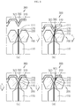
- FIGS. 4(a) to 4(d) are diagrams for illustrating a process that the electrode lead is coupled to the bus bar in the battery module according to the first embodiment of the present disclosure.
- FIGS. 4(a) to 4(d) only a portion of FIG. 2 , namely a portion A of FIG. 2 , is depicted.
- the bus bar 200 is disposed adjacent to the electrode lead 111.
- the welding jig 300 moves from an upper side to a lower side to press the electrode lead 111.
- the electrode lead 111 is bent to contact the inclined portion 210 of the bus bar 200.
- the electrode lead 111 is electrically coupled to the inclined portion 210 of the bus bar 200 through the opening 330 of the welding jig 300 by means of the welding 500, for example laser welding.
- the electrode leads 111 and the bus bars 200 may be closely adhered to each other and the electrode leads 111 may be respectively coupled to the bus bar 200 without bending the electrode leads 111, thereby preventing the electrode leads 111 from overlapping and thus improving the welding property.
- FIGS. 5(a) to 5(d) are diagrams for illustrating a process that an electrode lead is coupled to a bus bar in a battery module according to the second embodiment of the present disclosure.
- the second embodiment of the present disclosure is different from the first embodiment in the point that the electrode lead 111 is not welded at the inclined portion 210 of the bus bar 200 but is welded at a horizontal portion 220 of the bus bar 200.
- the bus bar 200 may have a horizontal portion 220 extending horizontally from the inclined portion 210, in addition to the inclined portion 210.
- a first bent portion 115 and a second bent portion 116 are formed at the electrode lead 111.
- the first bent portion 115 may be formed in a way that the electrode lead 111 is bent at a slope corresponding to the inclination of the inclined portion 210 so that the electrode lead 111 comes into contact with the inclined portion 210 of the bus bar 200, similar to the first embodiment.
- the second bent portion 116 may be formed in a way that the electrode lead 111 is bent to correspond to the horizontal portion 220 so that the electrode lead 111 may come into contact with the horizontal portion 220 of the bus bar 200.
- the electrode lead 111 may be welded 500 at the horizontal portion 220 of the bus bar 200 to be coupled to the bus bar 200, and the opening 330 for the welding 500 at the welding jig 300 may be provided in the bus bar contacting portion 310.
- the bus bar 200 is disposed adjacent to the electrode lead 111.
- the welding jig 300 is moved from an upper side to a lower side to press the electrode lead 111.
- the electrode lead 111 is bent to come into contact with the inclined portion 210 of the bus bar 200 and the horizontal portion 220 of the bus bar 200.
- the electrode lead 111 is electrically coupled to the horizontal portion 220 of the bus bar 200 through the opening 330 of the welding jig 300 by means of the welding 500, for example laser welding.
- FIG. 6 is a schematic side sectioned view showing a state before an electrode lead is coupled to a bus bar in a battery module according to the third embodiment of the present disclosure
- FIG. 7 is a schematic side sectioned view showing a state after the electrode lead is coupled to the bus bar in the battery module according to the third embodiment of the present disclosure
- FIGS 8(a) to 8(c) are diagrams for illustrating a process that the electrode lead is coupled to the bus bar in the battery module according to the third embodiment of the present disclosure.
- FIGS 8(a) to 8(c) only a portion of FIG. 6 , namely a portion B of FIG. 6 , is depicted.
- the third embodiment of the present disclosure is different from the first and second embodiments in the point that the electrode lead 111 is coupled to the bus bar 200 not by welding but by an elastic member 400.
- the elastic member 400 may be configured to press the electrode leads 111 so that the electrode leads 111 are coupled to the plurality of bus bars 200, respectively. That is, since the electrode leads 111 are pressed by an elastic force of the elastic member 400, the electrode leads 111 may be electrically coupled to the bus bars 200 without welding.
- the elastic member 400 may have a variety of configurations, for example, a leaf spring.
- the elastic member 400 may include a support portion 410 and a pressing portion 420.
- the support portion 410 is supported in contact with the bus bar 200 at an upper side of the bus bar 200.
- the support portion 410 may be in contact with, for example, the horizontal portion 220 of the bus bar 200.
- the pressing portion 420 may be configured to extend from the support portion 410 and press the electrode lead 111 while moving, for example, from an upper side to a lower side of the electrode lead 111.
- the pressing portion 420 may be provided in plural corresponding to the number of the electrode leads 111.
- the welding jig 300 is removed after the electrode lead 111 and the bus bar 200 are coupled.
- the elastic member 400 is inserted between the bus bars 200 and maintained so that the electrode leads 111 are in contact with the bus bars 200.
- the bus bar 200 may have an inclined portion 210 formed therein, and the elastic member 400 presses the electrode leads 111 so that the electrode leads 111 are coupled to the inclined portions 210 of the plurality of bus bars 200, respectively.
- the elastic member 400 may also press the electrode leads 111 so that the electrode leads 111 contact both the inclined portion 210 and the horizontal portion 220 of the bus bar 200, without being limited to the above.
- the bus bar 200 is disposed adjacent to the electrode lead 111.
- the elastic member 400 presses the electrode lead 111 while moving from an upper side to a lower side.
- the electrode lead 111 comes into contact with the inclined portion 210 of the bus bar 200 and is electrically connected thereto by the elastic member 400.
- a battery pack (not shown) according to an embodiment of the present disclosure may include one or more battery modules according to an embodiment of the present disclosure as described above. Also, in addition to the battery modules, the battery pack (not shown) may further includes a case for accommodating the battery modules, and various devices for controlling charge and discharge of the battery modules, such as a BMS, a current sensor, a fuse, and the like.
- a vehicle (not shown) may include the battery module or the battery pack (not shown) described above, and the battery pack (not shown) may include the battery module.
- the battery module according to an embodiment of the present disclosure may be applied to the vehicle (not shown), for example, a predetermined vehicle (not shown) provided to use electricity like an electric vehicle or a hybrid electric vehicle.
- a plurality of battery cells 110 are stacked to form a battery cell stack 100.
- the number of battery cells 110 is not limited.
- a plurality of bus bars 200 are disposed adjacent to electrode leads 111 respectively provided at the plurality of battery cells 110, respectively.
- the bus bar 200 may be disposed between neighboring electrode leads 111.
- the welding jig 300 presses the electrode leads 111 while moving, for example, from an upper side to a lower side of the electrode leads 111 so that the electrode leads 111 come into contact with the respective bus bars 200.
- the pressing bending portion 320 of the welding jig 300 may press the electrode lead 111.
- the electrode leads 111 and the bus bars 200 are welded 500, for example laser-welded, through the opening 330 formed in the welding jig 300, thereby electrically coupling the electrode leads 111 and the bus bars 200.
- an inclined portion 210 may be formed at the bus bar 200, and the electrode lead 111 may be welded 500 at an inclined portion 210 of the bus bar 200 to be coupled to the bus bar 200 after being bent by the welding jig 300.
- the bus bar 200 may have an inclined portion 210 and a horizontal portion 220 extending horizontally from the inclined portion 210, and the electrode lead 111 may be bent by the welding jig 300 and then welded 500 at the horizontal portion 220 of the bus bar 200 to be coupled to the bus bar 200.
- the present disclosure is directed to a battery module, a battery pack including the battery module, and a method for producing the battery module, and is particularly applicable to industries associated with a secondary battery.
Landscapes
- Chemical & Material Sciences (AREA)
- Chemical Kinetics & Catalysis (AREA)
- Electrochemistry (AREA)
- General Chemical & Material Sciences (AREA)
- Connection Of Batteries Or Terminals (AREA)
- Battery Mounting, Suspending (AREA)
Abstract
Description
- The present application claims priority to Korean Patent Application No.
10-2017-0064794 filed on May 25, 2017 - The present disclosure relates to a battery module, a battery pack including the battery module, and a method for producing the battery module, and more particularly, to a battery module capable of coupling electrode leads to a bus bar without bending the electrode leads, a battery pack including the battery module, and a method for producing the battery module.
- As technology development and demand for a mobile device have increased, demand for a secondary battery as an energy source has rapidly increased. Conventionally, a nickel-cadmium battery or a hydrogen ion battery has been used as the secondary battery. However, a lithium secondary battery is recently widely used because charging and discharging is free due to rare memory effect in comparison with a nickel-based secondary battery, a self-discharge rate is very low, and an energy density is high.
- The lithium secondary battery mainly uses a lithium oxide and a carbonaceous material as a positive electrode active material and a negative electrode active material, respectively. The lithium secondary battery includes an electrode assembly in which a positive electrode plate and a negative electrode plate, respectively coated with the positive electrode active material and the negative electrode active material, are arranged with a separator therebetween, and an outer member, that is a battery case, which seals and receives the electrode assembly together with an electrolyte solution.
- The lithium secondary battery includes a positive electrode, a negative electrode, and a separator interposed therebetween and an electrolyte. Depending on which material is used for the positive electrode active material and the negative electrode active material, the lithium secondary battery is classified into a lithium ion battery (LIB) and a polymer lithium ion battery (PLIB). Generally, an electrode of the lithium secondary battery is prepared by applying the positive or negative electrode active material to a current collector made of aluminum or copper sheet, mesh, film, foil, or the like and then drying the same.
-
FIG. 1 is a diagram showing that an electrode lead and a bus bar provided in a conventional battery cell are electrically coupled to each other. Referring toFIG. 1 , in the conventional art, electrode leads 20 respectively provided to a plurality ofbattery cells 10 are bent to contact a surface of abus bar 30, and then bonded thereto by welding 40. In this case, a lot of manual works are demanded to a worker in order to maintain a bending shape of the electrode leads 20, and the electrode leads 20 and thebus bar 30 are not closely adhered to each other due to an elastic recovery force of the electrode leads 20 made of a metal. In addition, since the plurality of electrode leads 20 are overlapped at one point of thebus bar 30 and then welded 40, the weldability is deteriorated. - The present disclosure is directed to providing a battery module capable of closely adhering electrode leads and a bus bar to each other by coupling the electrode leads to the bus bar without bending the electrode leads, a battery pack including the battery module, and a method for producing the battery module.
- The present disclosure is also directed to providing a battery module capable of having improved weldability since the electrode leads are not overlapped, a battery pack including the battery module, and a method for producing the battery module.
- The present disclosure is also directed to providing a battery module capable of improving an automation ratio of the production line by eliminating a manual process for bending the electrode leads, a battery pack including the battery module, and a method for producing the battery module.
- In one aspect of the present disclosure, there is provided a battery module, comprising: a battery cell stack having a plurality of battery cells stacked; and a plurality of bus bars respectively disposed adjacent to electrode leads respectively provided at the plurality of battery cells, wherein the electrode leads respectively provided at the plurality of battery cells are electrically connected to the plurality of bus bars, respectively.
- Also, at least one of the plurality of bus bars may be disposed between the electrode leads.
- In addition, the bus bar may have an inclined portion.
- Also, the electrode lead may have a first bent portion bent at a slope corresponding to the inclination of the inclined portion so that the electrode lead comes into contact with the inclined portion of the bus bar.
- In addition, the electrode lead may be welded at the inclined portion of the bus bar to be coupled to the bus bar.
- Also, the bus bar may have an inclined portion and a horizontal portion horizontally extending from the inclined portion.
- In addition, the electrode lead may have a first bent portion bent at a slope corresponding to the inclination of the inclined portion so that the electrode lead comes into contact with the inclined portion of the bus bar, and a second bent portion bent corresponding to the horizontal portion so that the electrode lead comes into contact with the horizontal portion of the bus bar.
- Also, the electrode lead may be welded at the horizontal portion of the bus bar to be coupled to the bus bar.
- In addition, the battery module may further comprise an elastic member configured to press the electrode leads so that the electrode leads are respectively coupled to the plurality of bus bars.
- Also, the elastic member may include: a support portion contacting with and supported by the bus bar at an upper side of the bus bar; and a plurality of pressing portions extending from the support portion to press the electrode leads.
- In addition, the bus bar may have an inclined portion, and the elastic member may press the electrode leads so that the electrode leads are respectively coupled to the inclined portions of the plurality of bus bars.
- Meanwhile, in another aspect of the present disclosure, there is also provided a battery pack including the battery module described above, and there is also provided a vehicle including the battery module.
- Meanwhile, in another aspect of the present disclosure, there is also provided a method for producing a battery module, comprising: stacking a plurality of battery cells; disposing a plurality of bus bars adjacent to electrode leads respectively provided at the plurality of battery cells; by a welding jig, pressing the electrode leads so that the electrode leads come into contact with the bus bars, respectively; and welding the electrode leads and the bus bars through an opening formed in the welding jig.
- Also, the bus bar may have an inclined portion, and the electrode lead may be welded at the inclined portion of the bus bar to be coupled to the bus bar.
- In addition, the bus bar may have an inclined portion and a horizontal portion horizontally extending from the inclined portion, and the electrode lead may be welded at the horizontal portion of the bus bar to be coupled to the bus bar.
- According to the embodiments of the present disclosure, since the electrode leads may be coupled to each bus bar without being bent, the electrode leads are not restored by an elastic recovery force, thereby allowing the electrode leads and the bus bar to be closely adhered.
- Also, since the plurality of electrode leads are respectively coupled to the plurality of bus bars, the electrode leads are not overlapped, thereby improving the weldability.
- In addition, since a manual process for bending the electrode leads is eliminated, an automation ratio of the production line may be improved.
-
-
FIG. 1 is a diagram showing that an electrode lead and a bus bar provided in a conventional battery cell are electrically coupled to each other. -
FIG. 2 is a schematic side sectioned view showing a state before an electrode lead is coupled to a bus bar in a battery module according to the first embodiment of the present disclosure. -
FIG. 3 is a schematic side sectioned view showing a state after the electrode lead is coupled to the bus bar in the battery module according to the first embodiment of the present disclosure. -
FIGS. 4(a) to 4(d) are diagrams for illustrating a process that the electrode lead is coupled to the bus bar in the battery module according to the first embodiment of the present disclosure. -
FIGS. 5(a) to 5(d) are diagrams for illustrating a process that an electrode lead is coupled to a bus bar in a battery module according to the second embodiment of the present disclosure. -
FIG. 6 is a schematic side sectioned view showing a state before an electrode lead is coupled to a bus bar in a battery module according to the third embodiment of the present disclosure. -
FIG. 7 is a schematic side sectioned view showing a state after the electrode lead is coupled to the bus bar in the battery module according to the third embodiment of the present disclosure. -
FIGS 8(a) to 8(c) are diagrams for illustrating a process that the electrode lead is coupled to the bus bar in the battery module according to the third embodiment of the present disclosure. - Hereinafter, preferred embodiments of the present disclosure will be described in detail with reference to the accompanying drawings. Prior to the description, it should be understood that the terms used in the specification and the appended claims should not be construed as limited to general and dictionary meanings, but interpreted based on the meanings and concepts corresponding to technical aspects of the present disclosure on the basis of the principle that the inventor is allowed to define terms appropriately for the best explanation. Therefore, the description proposed herein is just a preferable example for the purpose of illustrations only, not intended to limit the scope of the disclosure, so it should be understood that other equivalents and modifications could be made thereto without departing from the scope of the disclosure.
- In the drawings, the size of each element or a specific part of the element may be exaggerated, omitted, or schematically illustrated for convenience and clarity of a description. Thus, the size of each element does not entirely reflect the actual size of the element. A detailed description of well-known functions or elements associated with the present disclosure will be omitted if it unnecessarily obscures the subject matter of the present disclosure.
- The term, 'combine' or 'connect' as used herein, may refer not only to a case where one member and another member are directly combined or directly connected but also a case where one member is indirectly combined with another member via a connecting member or is indirectly connected.
-
FIG. 2 is a schematic side sectioned view showing a state before an electrode lead is coupled to a bus bar in a battery module according to the first embodiment of the present disclosure, andFIG. 3 is a schematic side sectioned view showing a state after the electrode lead is coupled to the bus bar in the battery module according to the first embodiment of the present disclosure. - Referring to
FIGS. 2 and3 , a battery module according to an embodiment of the present disclosure includes abattery cell stack 100 and a plurality ofbus bars 200. - The
battery cell stack 100 may be configured so that a plurality ofbattery cells 110 are stacked therein. Thebattery cells 110 may have various structures, and the plurality ofunit cells 110 may be stacked in various ways. Thebattery cell 110 may be configured so that a plurality of unit cells,, in each of which a positive electrode plate, a separator and a negative electrode plate are arranged in order, or a plurality of bi-cells, in each of which a positive electrode plate, a separator, a negative electrode plate, a separator, a positive electrode plate, a separator and a negative electrode plate are arranged in order, are stacked suitable for a battery capacity. - The
battery cell 110 may have anelectrode lead 111. Theelectrode lead 111 is a type of terminal that is exposed to the outside and connected to an external device, and theelectrode lead 111 may be made of a conductive material. Theelectrode lead 111 may include a positive electrode lead and a negative electrode lead. The positive electrode lead and the negative electrode lead may be disposed in opposite directions with respect to the longitudinal direction of thebattery cell 110, or the positive electrode lead and the negative electrode lead may be positioned in the same direction with respect to the longitudinal direction of thebattery cell 110. Theelectrode lead 111 is electrically coupled to thebus bar 200, explained later. - The
battery cell stack 100 may include a plurality of cartridges (not shown) for accommodating thebattery cells 110. Each cartridge (not shown) may be fabricated by injection-molding plastic, and a plurality of cartridges (not shown) having an accommodation portion for accommodating thebattery cell 110 may be stacked. A cartridge assembly in which a plurality of cartridges (not shown) are stacked may include a connector element or a terminal element. The connector element may include various types of electrical connecting components or connecting components for connecting to, for example, a battery management system (BMS) (not shown) capable of providing data on voltage or temperature of thebattery cells 110. In addition, the terminal element includes a positive electrode terminal and a negative electrode terminal as main terminals connected to thebattery cell 110, and the terminal element may have a terminal bolt to be electrically connected to the outside. Meanwhile, thebattery cell 110 may have various shapes. - The bus bars 200 are coupled to the electrode leads 111 to electrically connect the electrode leads 111. Here, the electric connection may include serial or parallel connection. The bus bars 200 are disposed adjacent to the electrode leads 111 to contact the electrode leads 111 provided at the
battery cells 110. Referring toFIG. 2 , the bus bars 200 may be disposed between the electrode leads 111. Here, at least one of the plurality ofbus bars 200 may be disposed between neighboring electrode leads 111, and thebus bar 200 disposed at an outermost side may be provided adjacent to apredetermined electrode lead 111. In addition, referring toFIG. 3 , the electrode leads 111 respectively provided at the plurality ofbattery cells 110 come into contact with and are electrically coupled to the plurality ofbus bars 200, respectively. - The
bus bar 200 may have various shapes, and, for example, as shown inFIGS. 2 and3 , aninclined portion 210 may be formed at thebus bar 200. In addition, theelectrode lead 111 may have a first bent portion 115 (seeFIG. 3 ) bent at a slope corresponding to the inclination of theinclined portion 210. That is, theelectrode lead 111 may be bent at the firstbent portion 115 of theelectrode lead 111, and then theelectrode lead 111 may come into contact with theinclined portion 210 of thebus bar 200. In addition, theelectrode lead 111 may be welded 500 at theinclined portion 210 of thebus bar 200 to be coupled to thebus bar 200. For this, awelding jig 300 with an inclination corresponding to theinclined portion 210 of thebus bar 200 may press theelectrode lead 111 at an upper side of theelectrode lead 111 to form the firstbent portion 115 at theelectrode lead 111. That is, if thewelding jig 300 presses the electrode leads 111, for example, downward at an upper side of the electrode leads 111 after the plurality ofbus bars 200 are respectively disposed between the electrode leads 111 or adjacent to the electrode leads 111, theelectrode lead 111 are bent toward theinclined portion 210 of thebus bar 200 to contact theinclined portion 210 of thebus bar 200. Here, anopening 330 may be formed in thewelding jig 300, and thewelding 500, for example, laser welding, may be performed through theopening 330 of thewelding jig 300 to electrically connect the electrode leads 111 to theinclined portions 210 of the plurality ofbus bars 200, respectively. Thewelding jig 300 may include a busbar contacting portion 310 contacting an upper side of thebus bar 200 and apressing bending portion 320 extending from the busbar contacting portion 310 to press and bend theelectrode lead 111. In addition, at thewelding jig 300, theopening 330 for thewelding 500 may be provided in thepressing bending portion 320. - Hereinafter, the operation and effect of the battery module according to the first embodiment of the present disclosure will be described with reference to the drawings.
-
FIGS. 4(a) to 4(d) are diagrams for illustrating a process that the electrode lead is coupled to the bus bar in the battery module according to the first embodiment of the present disclosure. InFIGS. 4(a) to 4(d) , only a portion ofFIG. 2 , namely a portion A ofFIG. 2 , is depicted. - Referring to
FIG. 4(a) , thebus bar 200 is disposed adjacent to theelectrode lead 111. Referring toFIG. 4(b) , thewelding jig 300 moves from an upper side to a lower side to press theelectrode lead 111. Referring toFIG. 4(c) , theelectrode lead 111 is bent to contact theinclined portion 210 of thebus bar 200. Referring toFIG. 4(d) , theelectrode lead 111 is electrically coupled to theinclined portion 210 of thebus bar 200 through theopening 330 of thewelding jig 300 by means of thewelding 500, for example laser welding. - As a result, the electrode leads 111 and the bus bars 200 may be closely adhered to each other and the electrode leads 111 may be respectively coupled to the
bus bar 200 without bending the electrode leads 111, thereby preventing the electrode leads 111 from overlapping and thus improving the welding property. -
FIGS. 5(a) to 5(d) are diagrams for illustrating a process that an electrode lead is coupled to a bus bar in a battery module according to the second embodiment of the present disclosure. - Hereinafter, the function and effect of a battery module according to the second embodiment according to the present disclosure will be described with reference to the drawings, but features common to the battery module according to the first embodiment of the present disclosure will not be described again in detail.
- The second embodiment of the present disclosure is different from the first embodiment in the point that the
electrode lead 111 is not welded at theinclined portion 210 of thebus bar 200 but is welded at ahorizontal portion 220 of thebus bar 200. - Referring to
FIGS. 5(a) to 5(d) , thebus bar 200 may have ahorizontal portion 220 extending horizontally from theinclined portion 210, in addition to theinclined portion 210. In addition, a firstbent portion 115 and a secondbent portion 116 are formed at theelectrode lead 111. The firstbent portion 115 may be formed in a way that theelectrode lead 111 is bent at a slope corresponding to the inclination of theinclined portion 210 so that theelectrode lead 111 comes into contact with theinclined portion 210 of thebus bar 200, similar to the first embodiment. In addition, the secondbent portion 116 may be formed in a way that theelectrode lead 111 is bent to correspond to thehorizontal portion 220 so that theelectrode lead 111 may come into contact with thehorizontal portion 220 of thebus bar 200. - In addition, the
electrode lead 111 may be welded 500 at thehorizontal portion 220 of thebus bar 200 to be coupled to thebus bar 200, and theopening 330 for thewelding 500 at thewelding jig 300 may be provided in the busbar contacting portion 310. - Referring to
FIG. 5(a) , thebus bar 200 is disposed adjacent to theelectrode lead 111. Referring toFIG. 5(b) , thewelding jig 300 is moved from an upper side to a lower side to press theelectrode lead 111. Referring toFIG. 5(c) , theelectrode lead 111 is bent to come into contact with theinclined portion 210 of thebus bar 200 and thehorizontal portion 220 of thebus bar 200. Referring toFIG. 5(d) , theelectrode lead 111 is electrically coupled to thehorizontal portion 220 of thebus bar 200 through theopening 330 of thewelding jig 300 by means of thewelding 500, for example laser welding. -
FIG. 6 is a schematic side sectioned view showing a state before an electrode lead is coupled to a bus bar in a battery module according to the third embodiment of the present disclosure,FIG. 7 is a schematic side sectioned view showing a state after the electrode lead is coupled to the bus bar in the battery module according to the third embodiment of the present disclosure, andFIGS 8(a) to 8(c) are diagrams for illustrating a process that the electrode lead is coupled to the bus bar in the battery module according to the third embodiment of the present disclosure. InFIGS 8(a) to 8(c) , only a portion ofFIG. 6 , namely a portion B ofFIG. 6 , is depicted. - Hereinafter, the function and effect of the battery module according to the third embodiment according to the present disclosure will be described with reference to the drawings, but features common to the battery module according to the first and second embodiments of the present disclosure will not be described again in detail.
- The third embodiment of the present disclosure is different from the first and second embodiments in the point that the
electrode lead 111 is coupled to thebus bar 200 not by welding but by anelastic member 400. - Referring to
FIGS. 6 and 7 , theelastic member 400 may be configured to press the electrode leads 111 so that the electrode leads 111 are coupled to the plurality ofbus bars 200, respectively. That is, since the electrode leads 111 are pressed by an elastic force of theelastic member 400, the electrode leads 111 may be electrically coupled to the bus bars 200 without welding. - The
elastic member 400 may have a variety of configurations, for example, a leaf spring. Theelastic member 400 may include asupport portion 410 and apressing portion 420. Thesupport portion 410 is supported in contact with thebus bar 200 at an upper side of thebus bar 200. Thesupport portion 410 may be in contact with, for example, thehorizontal portion 220 of thebus bar 200. Thepressing portion 420 may be configured to extend from thesupport portion 410 and press theelectrode lead 111 while moving, for example, from an upper side to a lower side of theelectrode lead 111. Thepressing portion 420 may be provided in plural corresponding to the number of the electrode leads 111. In the first and second embodiments, thewelding jig 300 is removed after theelectrode lead 111 and thebus bar 200 are coupled. However, in the third embodiment, theelastic member 400 is inserted between the bus bars 200 and maintained so that the electrode leads 111 are in contact with the bus bars 200. - Referring to
FIGS. 6 and 7 , similar to the first and second embodiments, thebus bar 200 may have aninclined portion 210 formed therein, and theelastic member 400 presses the electrode leads 111 so that the electrode leads 111 are coupled to theinclined portions 210 of the plurality ofbus bars 200, respectively. However, theelastic member 400 may also press the electrode leads 111 so that the electrode leads 111 contact both theinclined portion 210 and thehorizontal portion 220 of thebus bar 200, without being limited to the above. - Referring to
FIG. 8(a) , thebus bar 200 is disposed adjacent to theelectrode lead 111. Referring toFIG. 8(b) , theelastic member 400 presses theelectrode lead 111 while moving from an upper side to a lower side. Referring toFIG. 8(c) , theelectrode lead 111 comes into contact with theinclined portion 210 of thebus bar 200 and is electrically connected thereto by theelastic member 400. - Meanwhile, a battery pack (not shown) according to an embodiment of the present disclosure may include one or more battery modules according to an embodiment of the present disclosure as described above. Also, in addition to the battery modules, the battery pack (not shown) may further includes a case for accommodating the battery modules, and various devices for controlling charge and discharge of the battery modules, such as a BMS, a current sensor, a fuse, and the like.
- Meanwhile, a vehicle (not shown) according to an embodiment of the present disclosure may include the battery module or the battery pack (not shown) described above, and the battery pack (not shown) may include the battery module. In addition, the battery module according to an embodiment of the present disclosure may be applied to the vehicle (not shown), for example, a predetermined vehicle (not shown) provided to use electricity like an electric vehicle or a hybrid electric vehicle.
- Hereinafter, a method of producing a battery module according to an embodiment of the present disclosure will be described with reference to the drawings.
- First, a plurality of
battery cells 110 are stacked to form abattery cell stack 100. The number ofbattery cells 110 is not limited. In addition, a plurality ofbus bars 200 are disposed adjacent to electrode leads 111 respectively provided at the plurality ofbattery cells 110, respectively. Here, thebus bar 200 may be disposed between neighboring electrode leads 111. In addition, thewelding jig 300 presses the electrode leads 111 while moving, for example, from an upper side to a lower side of the electrode leads 111 so that the electrode leads 111 come into contact with the respective bus bars 200. Here, thepressing bending portion 320 of thewelding jig 300 may press theelectrode lead 111. In addition, the electrode leads 111 and the bus bars 200 are welded 500, for example laser-welded, through theopening 330 formed in thewelding jig 300, thereby electrically coupling the electrode leads 111 and the bus bars 200. - In addition, an
inclined portion 210 may be formed at thebus bar 200, and theelectrode lead 111 may be welded 500 at aninclined portion 210 of thebus bar 200 to be coupled to thebus bar 200 after being bent by thewelding jig 300. Alternatively, thebus bar 200 may have aninclined portion 210 and ahorizontal portion 220 extending horizontally from theinclined portion 210, and theelectrode lead 111 may be bent by thewelding jig 300 and then welded 500 at thehorizontal portion 220 of thebus bar 200 to be coupled to thebus bar 200. - The present disclosure has been described in detail. However, it should be understood that the detailed description and specific examples, while indicating preferred embodiments of the disclosure, are given by way of illustration only, since various changes and modifications within the scope of the disclosure will become apparent to those skilled in the art from this detailed description.
- The present disclosure is directed to a battery module, a battery pack including the battery module, and a method for producing the battery module, and is particularly applicable to industries associated with a secondary battery.
Claims (16)
- A battery module, comprising:a battery cell stack having a plurality of battery cells stacked; anda plurality of bus bars respectively disposed adjacent to electrode leads respectively provided at the plurality of battery cells,wherein the electrode leads respectively provided at the plurality of battery cells are electrically connected to the plurality of bus bars, respectively.
- The battery module according to claim 1,
wherein at least one of the plurality of bus bars is disposed between the electrode leads. - The battery module according to claim 1,
wherein the bus bar has an inclined portion. - The battery module according to claim 3,
wherein the electrode lead has a first bent portion bent at a slope corresponding to the inclination of the inclined portion so that the electrode lead comes into contact with the inclined portion of the bus bar. - The battery module according to claim 4,
wherein the electrode lead is welded at the inclined portion of the bus bar to be coupled to the bus bar. - The battery module according to claim 1,
wherein the bus bar has an inclined portion and a horizontal portion horizontally extending from the inclined portion. - The battery module according to claim 6,
wherein the electrode lead has a first bent portion bent at a slope corresponding to the inclination of the inclined portion so that the electrode lead comes into contact with the inclined portion of the bus bar, and a second bent portion bent corresponding to the horizontal portion so that the electrode lead comes into contact with the horizontal portion of the bus bar. - The battery module according to claim 7,
wherein the electrode lead is welded at the horizontal portion of the bus bar to be coupled to the bus bar. - The battery module according to claim 1, further comprising:
an elastic member configured to press the electrode leads so that the electrode leads are respectively coupled to the plurality of bus bars. - The battery module according to claim 9,
wherein the elastic member includes:a support portion contacting with and supported by the bus bar at an upper side of the bus bar; anda plurality of pressing portions extending from the support portion to press the electrode leads. - The battery module according to claim 9,
wherein the bus bar has an inclined portion, and
wherein the elastic member presses the electrode leads so that the electrode leads are respectively coupled to the inclined portions of the plurality of bus bars. - A battery pack, comprising a battery module defined in any one of claims 1 to 11.
- A vehicle, comprising a battery module defined in any one of claims 1 to 11.
- A method for producing a battery module, comprising:stacking a plurality of battery cells;disposing a plurality of bus bars adjacent to electrode leads respectively provided at the plurality of battery cells;by a welding jig, pressing the electrode leads so that the electrode leads come into contact with the bus bars, respectively; andwelding the electrode leads and the bus bars through an opening formed in the welding jig.
- The method for producing a battery module according to claim 14,
wherein the bus bar has an inclined portion, and the electrode lead is welded at the inclined portion of the bus bar to be coupled to the bus bar. - The method for producing a battery module according to claim 14,
wherein the bus bar has an inclined portion and a horizontal portion horizontally extending from the inclined portion, and the electrode lead is welded at the horizontal portion of the bus bar to be coupled to the bus bar.
Applications Claiming Priority (2)
| Application Number | Priority Date | Filing Date | Title |
|---|---|---|---|
| KR1020170064794A KR102157377B1 (en) | 2017-05-25 | 2017-05-25 | Battery module and battery pack including the same and manufacturing method for battery module |
| PCT/KR2018/000360 WO2018216873A1 (en) | 2017-05-25 | 2018-01-08 | Battery module, battery pack comprising same and battery module manufacturing method |
Publications (3)
| Publication Number | Publication Date |
|---|---|
| EP3547394A1 true EP3547394A1 (en) | 2019-10-02 |
| EP3547394A4 EP3547394A4 (en) | 2019-12-25 |
| EP3547394B1 EP3547394B1 (en) | 2024-03-06 |
Family
ID=64395642
Family Applications (1)
| Application Number | Title | Priority Date | Filing Date |
|---|---|---|---|
| EP18806385.3A Active EP3547394B1 (en) | 2017-05-25 | 2018-01-08 | Battery module, battery pack comprising same |
Country Status (8)
| Country | Link |
|---|---|
| US (3) | US11362402B2 (en) |
| EP (1) | EP3547394B1 (en) |
| JP (1) | JP6816290B2 (en) |
| KR (1) | KR102157377B1 (en) |
| CN (1) | CN110050361B (en) |
| ES (1) | ES2974698T3 (en) |
| HU (1) | HUE065945T2 (en) |
| WO (1) | WO2018216873A1 (en) |
Families Citing this family (7)
| Publication number | Priority date | Publication date | Assignee | Title |
|---|---|---|---|---|
| KR20210087815A (en) * | 2020-01-03 | 2021-07-13 | 주식회사 엘지에너지솔루션 | Battery pack having improved coupling structure and automobile including same |
| KR20220009251A (en) | 2020-07-15 | 2022-01-24 | 주식회사 엘지에너지솔루션 | Electrode Lead Bending and Welding Device and Welding Method Using the Same |
| DE102020123851A1 (en) * | 2020-09-14 | 2022-03-17 | Volkswagen Aktiengesellschaft | Method for producing an electrical coupling of battery cells of a battery module and battery module |
| KR20220045851A (en) * | 2020-10-06 | 2022-04-13 | 주식회사 엘지에너지솔루션 | Battery module and battery pack including the same and vehicle including the same |
| WO2023163469A1 (en) * | 2022-02-22 | 2023-08-31 | 주식회사 엘지에너지솔루션 | Electrode lead alignment masking device |
| WO2024136490A1 (en) * | 2022-12-22 | 2024-06-27 | 주식회사 엘지에너지솔루션 | Bus bar assembly and battery module comprising same |
| KR102682829B1 (en) * | 2024-01-26 | 2024-07-08 | 주식회사 모아 | Diagonal Bus-bar Assembly for Pouch-type Battery Cell |
Family Cites Families (44)
| Publication number | Priority date | Publication date | Assignee | Title |
|---|---|---|---|---|
| US5001024A (en) * | 1989-10-31 | 1991-03-19 | Eberle William J | Storage battery and method of manufacturing |
| JP2001076790A (en) * | 1999-09-02 | 2001-03-23 | Sumitomo Wiring Syst Ltd | Connection structure of terminal |
| JP4227762B2 (en) | 2002-05-31 | 2009-02-18 | 富士重工業株式会社 | Assembled battery unit and connecting method of assembled battery unit |
| JP4237552B2 (en) * | 2003-06-05 | 2009-03-11 | 矢崎総業株式会社 | Battery connection plate |
| JP4690013B2 (en) | 2004-10-29 | 2011-06-01 | 日本電気株式会社 | Connection apparatus and electrical device assembly using the same |
| JP2007087907A (en) | 2005-09-26 | 2007-04-05 | Fuji Heavy Ind Ltd | Case structure of power storage unit cell |
| JP4829587B2 (en) * | 2005-10-14 | 2011-12-07 | 日本電気株式会社 | Electrical device assembly and manufacturing method thereof |
| JP5046956B2 (en) * | 2005-12-01 | 2012-10-10 | 日本電気株式会社 | Method for manufacturing electrical device assembly |
| JP5252836B2 (en) * | 2007-05-29 | 2013-07-31 | 三洋電機株式会社 | Pack battery |
| JP5340676B2 (en) * | 2008-08-29 | 2013-11-13 | 三洋電機株式会社 | Battery system |
| JP5094783B2 (en) * | 2009-04-28 | 2012-12-12 | エネルギー コントロール リミテッド | High conductivity connection structure |
| CN101877413B (en) * | 2009-04-30 | 2013-10-30 | 比亚迪股份有限公司 | Monomer battery and power battery pack containing same |
| JP5582815B2 (en) | 2010-02-18 | 2014-09-03 | 日本航空電子工業株式会社 | Battery connection device |
| JP5615045B2 (en) * | 2010-05-28 | 2014-10-29 | 日本航空電子工業株式会社 | Battery connection structure and connection method |
| JP2012059362A (en) | 2010-09-03 | 2012-03-22 | Mitsubishi Heavy Ind Ltd | Battery pack |
| KR101023184B1 (en) | 2010-11-01 | 2011-03-18 | 쓰리피시스템(주) | System and method for welding the battery-module |
| CN102064291B (en) * | 2010-12-14 | 2013-04-10 | 长丰集团有限责任公司 | Integrally-impacted stacking battery module |
| EP2672547B1 (en) * | 2011-04-26 | 2017-05-31 | LG Chem, Ltd. | Bus bar having a novel structure, and battery module including same |
| US20120295150A1 (en) * | 2011-05-17 | 2012-11-22 | GM Global Technology Operations LLC | Battery module and method of manufacturing the same |
| EP2722911B1 (en) * | 2011-06-17 | 2019-03-13 | LG Chem, Ltd. | Soldering connector, battery module having the same and battery pack comprising the battery module. |
| US8609276B2 (en) * | 2011-06-23 | 2013-12-17 | Samsung Sdi Co., Ltd. | Battery pack |
| JP5834769B2 (en) * | 2011-10-26 | 2015-12-24 | 株式会社オートネットワーク技術研究所 | Battery wiring module |
| JP2013214497A (en) * | 2012-03-08 | 2013-10-17 | Nissan Motor Co Ltd | Battery pack |
| KR101487152B1 (en) * | 2012-04-05 | 2015-01-27 | 주식회사 엘지화학 | Unit Module Assembly and Battery Module Comprising The Same |
| KR102024002B1 (en) * | 2012-07-05 | 2019-09-23 | 에스케이이노베이션 주식회사 | Battery pack |
| US9136621B1 (en) | 2012-08-14 | 2015-09-15 | Ciena Corporation | Guides and tab arrangement to retain a card having an edge connector and method of use |
| KR20140093424A (en) * | 2013-01-18 | 2014-07-28 | 타이코에이엠피(유) | Battery module |
| JP6011876B2 (en) * | 2013-09-13 | 2016-10-19 | 株式会社オートネットワーク技術研究所 | Power storage module |
| US10218027B2 (en) * | 2013-11-11 | 2019-02-26 | A123 Systems, LLC | Vehicle starter battery |
| KR20150067694A (en) * | 2013-12-10 | 2015-06-18 | 한국단자공업 주식회사 | Connecting apparatus for battery Module |
| KR101558694B1 (en) * | 2013-12-18 | 2015-10-07 | 현대자동차주식회사 | High voltage battery for vehicle |
| JP6289899B2 (en) * | 2013-12-26 | 2018-03-07 | 株式会社東芝 | Nonaqueous electrolyte battery, assembled battery and storage battery device |
| PL3109925T3 (en) | 2014-03-31 | 2022-07-18 | Lg Energy Solution, Ltd. | Battery module and battery pack comprising same |
| KR101565115B1 (en) | 2014-03-31 | 2015-11-02 | (주)탑전지 | Battery Pack and method for manufacturing the same |
| KR101750597B1 (en) * | 2014-04-30 | 2017-06-23 | 주식회사 엘지화학 | Laser welding apparatus |
| JP6359362B2 (en) * | 2014-07-07 | 2018-07-18 | 株式会社東芝 | Battery module |
| CN204991788U (en) * | 2015-05-08 | 2016-01-20 | 余正明 | Battery connecting piece and battery connector |
| CN105024224A (en) * | 2015-08-18 | 2015-11-04 | 德力西电气有限公司 | Plug-in assembly |
| KR102077272B1 (en) * | 2015-09-14 | 2020-02-13 | 주식회사 엘지화학 | Battery module and protecting structure applied for the same |
| CN205069739U (en) * | 2015-10-11 | 2016-03-02 | 深圳市沃特玛电池有限公司 | Battery tab connecting piece and have lithium cell of this battery tab connecting piece |
| KR20170064794A (en) | 2015-12-02 | 2017-06-12 | 이지형 | Bottle opener and the can be used regardless of the size of the bottle cap |
| CN106025162B (en) * | 2016-06-30 | 2019-11-08 | 上海捷新动力电池系统有限公司 | A kind of soft package battery module connection structure |
| CN106207067B (en) | 2016-08-30 | 2018-12-07 | 中航锂电(洛阳)有限公司 | Pole piece connection structure, pole piece connection method, collector and lithium battery |
| CN206179972U (en) * | 2016-11-29 | 2017-05-17 | 宁德时代新能源科技股份有限公司 | Battery module |
-
2017
- 2017-05-25 KR KR1020170064794A patent/KR102157377B1/en active IP Right Grant
-
2018
- 2018-01-08 US US16/346,021 patent/US11362402B2/en active Active
- 2018-01-08 ES ES18806385T patent/ES2974698T3/en active Active
- 2018-01-08 CN CN201880004906.7A patent/CN110050361B/en active Active
- 2018-01-08 JP JP2019538258A patent/JP6816290B2/en active Active
- 2018-01-08 EP EP18806385.3A patent/EP3547394B1/en active Active
- 2018-01-08 WO PCT/KR2018/000360 patent/WO2018216873A1/en unknown
- 2018-01-08 HU HUE18806385A patent/HUE065945T2/en unknown
-
2022
- 2022-05-10 US US17/740,603 patent/US11923564B2/en active Active
-
2024
- 2024-02-01 US US18/430,124 patent/US20240178530A1/en active Pending
Also Published As
| Publication number | Publication date |
|---|---|
| JP2020514985A (en) | 2020-05-21 |
| US20240178530A1 (en) | 2024-05-30 |
| US20190267603A1 (en) | 2019-08-29 |
| CN110050361B (en) | 2023-04-28 |
| ES2974698T3 (en) | 2024-07-01 |
| KR20180129170A (en) | 2018-12-05 |
| EP3547394A4 (en) | 2019-12-25 |
| WO2018216873A1 (en) | 2018-11-29 |
| JP6816290B2 (en) | 2021-01-20 |
| US11923564B2 (en) | 2024-03-05 |
| CN110050361A (en) | 2019-07-23 |
| HUE065945T2 (en) | 2024-06-28 |
| KR102157377B1 (en) | 2020-09-17 |
| US20220271404A1 (en) | 2022-08-25 |
| EP3547394B1 (en) | 2024-03-06 |
| US11362402B2 (en) | 2022-06-14 |
Similar Documents
| Publication | Publication Date | Title |
|---|---|---|
| US11923564B2 (en) | Method for producing battery module | |
| US11152671B2 (en) | Battery module and battery pack including the same | |
| EP3540817B1 (en) | Battery pack | |
| EP3584856B1 (en) | Battery module and battery pack comprising same | |
| EP3573131B1 (en) | Battery module and battery module manufacturing method | |
| EP3582286A1 (en) | Battery cell frame and battery module comprising same | |
| EP4084206A1 (en) | Battery module, and battery pack and vehicle comprising battery module | |
| KR20190112581A (en) | Voltage sensing module of terminal using elasticity and battery module comprising the same | |
| EP4138190A1 (en) | Battery module, and battery pack and automobile including same | |
| CN115066784A (en) | Battery module and battery pack and vehicle including the same |
Legal Events
| Date | Code | Title | Description |
|---|---|---|---|
| STAA | Information on the status of an ep patent application or granted ep patent |
Free format text: STATUS: THE INTERNATIONAL PUBLICATION HAS BEEN MADE |
|
| PUAI | Public reference made under article 153(3) epc to a published international application that has entered the european phase |
Free format text: ORIGINAL CODE: 0009012 |
|
| STAA | Information on the status of an ep patent application or granted ep patent |
Free format text: STATUS: REQUEST FOR EXAMINATION WAS MADE |
|
| 17P | Request for examination filed |
Effective date: 20190628 |
|
| AK | Designated contracting states |
Kind code of ref document: A1 Designated state(s): AL AT BE BG CH CY CZ DE DK EE ES FI FR GB GR HR HU IE IS IT LI LT LU LV MC MK MT NL NO PL PT RO RS SE SI SK SM TR |
|
| AX | Request for extension of the european patent |
Extension state: BA ME |
|
| A4 | Supplementary search report drawn up and despatched |
Effective date: 20191127 |
|
| RIC1 | Information provided on ipc code assigned before grant |
Ipc: H01M 2/26 20060101ALI20191121BHEP Ipc: H01M 2/10 20060101AFI20191121BHEP Ipc: H01M 2/20 20060101ALI20191121BHEP Ipc: H01M 2/30 20060101ALI20191121BHEP |
|
| DAV | Request for validation of the european patent (deleted) | ||
| DAX | Request for extension of the european patent (deleted) | ||
| STAA | Information on the status of an ep patent application or granted ep patent |
Free format text: STATUS: EXAMINATION IS IN PROGRESS |
|
| 17Q | First examination report despatched |
Effective date: 20201009 |
|
| STAA | Information on the status of an ep patent application or granted ep patent |
Free format text: STATUS: EXAMINATION IS IN PROGRESS |
|
| RAP1 | Party data changed (applicant data changed or rights of an application transferred) |
Owner name: LG ENERGY SOLUTION LTD. |
|
| RAP3 | Party data changed (applicant data changed or rights of an application transferred) |
Owner name: LG ENERGY SOLUTION, LTD. |
|
| REG | Reference to a national code |
Ref country code: DE Ref legal event code: R079 Ref document number: 602018066286 Country of ref document: DE Free format text: PREVIOUS MAIN CLASS: H01M0002100000 Ipc: H01M0050204000 |
|
| GRAP | Despatch of communication of intention to grant a patent |
Free format text: ORIGINAL CODE: EPIDOSNIGR1 |
|
| STAA | Information on the status of an ep patent application or granted ep patent |
Free format text: STATUS: GRANT OF PATENT IS INTENDED |
|
| RIC1 | Information provided on ipc code assigned before grant |
Ipc: H01M 50/517 20210101ALI20230718BHEP Ipc: H01M 50/503 20210101ALI20230718BHEP Ipc: H01M 50/55 20210101ALI20230718BHEP Ipc: H01M 50/548 20210101ALI20230718BHEP Ipc: H01M 50/505 20210101ALI20230718BHEP Ipc: H01M 50/204 20210101AFI20230718BHEP |
|
| INTG | Intention to grant announced |
Effective date: 20230801 |
|
| GRAS | Grant fee paid |
Free format text: ORIGINAL CODE: EPIDOSNIGR3 |
|
| P01 | Opt-out of the competence of the unified patent court (upc) registered |
Effective date: 20231205 |
|
| GRAA | (expected) grant |
Free format text: ORIGINAL CODE: 0009210 |
|
| STAA | Information on the status of an ep patent application or granted ep patent |
Free format text: STATUS: THE PATENT HAS BEEN GRANTED |
|
| AK | Designated contracting states |
Kind code of ref document: B1 Designated state(s): AL AT BE BG CH CY CZ DE DK EE ES FI FR GB GR HR HU IE IS IT LI LT LU LV MC MK MT NL NO PL PT RO RS SE SI SK SM TR |
|
| REG | Reference to a national code |
Ref country code: GB Ref legal event code: FG4D |
|
| REG | Reference to a national code |
Ref country code: CH Ref legal event code: EP |
|
| REG | Reference to a national code |
Ref country code: IE Ref legal event code: FG4D |
|
| REG | Reference to a national code |
Ref country code: DE Ref legal event code: R096 Ref document number: 602018066286 Country of ref document: DE |
|
| REG | Reference to a national code |
Ref country code: LT Ref legal event code: MG9D |
|
| REG | Reference to a national code |
Ref country code: HU Ref legal event code: AG4A Ref document number: E065945 Country of ref document: HU |
|
| REG | Reference to a national code |
Ref country code: ES Ref legal event code: FG2A Ref document number: 2974698 Country of ref document: ES Kind code of ref document: T3 Effective date: 20240701 |
|
| PG25 | Lapsed in a contracting state [announced via postgrant information from national office to epo] |
Ref country code: LT Free format text: LAPSE BECAUSE OF FAILURE TO SUBMIT A TRANSLATION OF THE DESCRIPTION OR TO PAY THE FEE WITHIN THE PRESCRIBED TIME-LIMIT Effective date: 20240306 |
|
| REG | Reference to a national code |
Ref country code: NL Ref legal event code: MP Effective date: 20240306 |
|
| PG25 | Lapsed in a contracting state [announced via postgrant information from national office to epo] |
Ref country code: GR Free format text: LAPSE BECAUSE OF FAILURE TO SUBMIT A TRANSLATION OF THE DESCRIPTION OR TO PAY THE FEE WITHIN THE PRESCRIBED TIME-LIMIT Effective date: 20240607 |
|
| PG25 | Lapsed in a contracting state [announced via postgrant information from national office to epo] |
Ref country code: RS Free format text: LAPSE BECAUSE OF FAILURE TO SUBMIT A TRANSLATION OF THE DESCRIPTION OR TO PAY THE FEE WITHIN THE PRESCRIBED TIME-LIMIT Effective date: 20240606 Ref country code: HR Free format text: LAPSE BECAUSE OF FAILURE TO SUBMIT A TRANSLATION OF THE DESCRIPTION OR TO PAY THE FEE WITHIN THE PRESCRIBED TIME-LIMIT Effective date: 20240306 |
|
| PG25 | Lapsed in a contracting state [announced via postgrant information from national office to epo] |
Ref country code: RS Free format text: LAPSE BECAUSE OF FAILURE TO SUBMIT A TRANSLATION OF THE DESCRIPTION OR TO PAY THE FEE WITHIN THE PRESCRIBED TIME-LIMIT Effective date: 20240606 Ref country code: NO Free format text: LAPSE BECAUSE OF FAILURE TO SUBMIT A TRANSLATION OF THE DESCRIPTION OR TO PAY THE FEE WITHIN THE PRESCRIBED TIME-LIMIT Effective date: 20240606 Ref country code: LT Free format text: LAPSE BECAUSE OF FAILURE TO SUBMIT A TRANSLATION OF THE DESCRIPTION OR TO PAY THE FEE WITHIN THE PRESCRIBED TIME-LIMIT Effective date: 20240306 Ref country code: HR Free format text: LAPSE BECAUSE OF FAILURE TO SUBMIT A TRANSLATION OF THE DESCRIPTION OR TO PAY THE FEE WITHIN THE PRESCRIBED TIME-LIMIT Effective date: 20240306 Ref country code: GR Free format text: LAPSE BECAUSE OF FAILURE TO SUBMIT A TRANSLATION OF THE DESCRIPTION OR TO PAY THE FEE WITHIN THE PRESCRIBED TIME-LIMIT Effective date: 20240607 Ref country code: FI Free format text: LAPSE BECAUSE OF FAILURE TO SUBMIT A TRANSLATION OF THE DESCRIPTION OR TO PAY THE FEE WITHIN THE PRESCRIBED TIME-LIMIT Effective date: 20240306 Ref country code: BG Free format text: LAPSE BECAUSE OF FAILURE TO SUBMIT A TRANSLATION OF THE DESCRIPTION OR TO PAY THE FEE WITHIN THE PRESCRIBED TIME-LIMIT Effective date: 20240306 |
|
| REG | Reference to a national code |
Ref country code: AT Ref legal event code: MK05 Ref document number: 1664445 Country of ref document: AT Kind code of ref document: T Effective date: 20240306 |
|
| PG25 | Lapsed in a contracting state [announced via postgrant information from national office to epo] |
Ref country code: SE Free format text: LAPSE BECAUSE OF FAILURE TO SUBMIT A TRANSLATION OF THE DESCRIPTION OR TO PAY THE FEE WITHIN THE PRESCRIBED TIME-LIMIT Effective date: 20240306 Ref country code: LV Free format text: LAPSE BECAUSE OF FAILURE TO SUBMIT A TRANSLATION OF THE DESCRIPTION OR TO PAY THE FEE WITHIN THE PRESCRIBED TIME-LIMIT Effective date: 20240306 |
|
| PG25 | Lapsed in a contracting state [announced via postgrant information from national office to epo] |
Ref country code: NL Free format text: LAPSE BECAUSE OF FAILURE TO SUBMIT A TRANSLATION OF THE DESCRIPTION OR TO PAY THE FEE WITHIN THE PRESCRIBED TIME-LIMIT Effective date: 20240306 |