EP3547296B1 - Méthode et système pour la simulation d'introduire un instrument oblong dans un sujet d'expérience - Google Patents
Méthode et système pour la simulation d'introduire un instrument oblong dans un sujet d'expérience Download PDFInfo
- Publication number
- EP3547296B1 EP3547296B1 EP19165720.4A EP19165720A EP3547296B1 EP 3547296 B1 EP3547296 B1 EP 3547296B1 EP 19165720 A EP19165720 A EP 19165720A EP 3547296 B1 EP3547296 B1 EP 3547296B1
- Authority
- EP
- European Patent Office
- Prior art keywords
- elongated instrument
- proximal section
- angular position
- distal
- longitudinal
- Prior art date
- Legal status (The legal status is an assumption and is not a legal conclusion. Google has not performed a legal analysis and makes no representation as to the accuracy of the status listed.)
- Active
Links
- 238000000034 method Methods 0.000 title claims description 36
- 238000003780 insertion Methods 0.000 title claims description 20
- 230000037431 insertion Effects 0.000 title claims description 20
- 238000006073 displacement reaction Methods 0.000 claims description 54
- 238000004088 simulation Methods 0.000 claims description 40
- 238000012545 processing Methods 0.000 claims description 26
- 238000012937 correction Methods 0.000 claims description 18
- 238000004891 communication Methods 0.000 claims description 16
- 238000005452 bending Methods 0.000 claims description 3
- 230000001133 acceleration Effects 0.000 claims 2
- 238000001356 surgical procedure Methods 0.000 description 13
- 238000012549 training Methods 0.000 description 6
- 210000001367 artery Anatomy 0.000 description 5
- 238000010586 diagram Methods 0.000 description 4
- 210000000056 organ Anatomy 0.000 description 4
- 210000003462 vein Anatomy 0.000 description 4
- 230000006870 function Effects 0.000 description 3
- 238000001839 endoscopy Methods 0.000 description 2
- 238000002324 minimally invasive surgery Methods 0.000 description 2
- 230000003287 optical effect Effects 0.000 description 2
- 239000007787 solid Substances 0.000 description 2
- 238000013519 translation Methods 0.000 description 2
- 230000000007 visual effect Effects 0.000 description 2
- 230000005355 Hall effect Effects 0.000 description 1
- 241001465754 Metazoa Species 0.000 description 1
- 230000005540 biological transmission Effects 0.000 description 1
- 239000008280 blood Substances 0.000 description 1
- 210000004369 blood Anatomy 0.000 description 1
- 210000004204 blood vessel Anatomy 0.000 description 1
- 230000001419 dependent effect Effects 0.000 description 1
- 230000002526 effect on cardiovascular system Effects 0.000 description 1
- 238000002674 endoscopic surgery Methods 0.000 description 1
- 230000002496 gastric effect Effects 0.000 description 1
- 230000010247 heart contraction Effects 0.000 description 1
- 230000001939 inductive effect Effects 0.000 description 1
- 230000002452 interceptive effect Effects 0.000 description 1
- 238000002357 laparoscopic surgery Methods 0.000 description 1
- WABPQHHGFIMREM-UHFFFAOYSA-N lead(0) Chemical compound [Pb] WABPQHHGFIMREM-UHFFFAOYSA-N 0.000 description 1
- 238000007726 management method Methods 0.000 description 1
- 238000012978 minimally invasive surgical procedure Methods 0.000 description 1
- 230000029058 respiratory gaseous exchange Effects 0.000 description 1
Images


Classifications
-
- G—PHYSICS
- G16—INFORMATION AND COMMUNICATION TECHNOLOGY [ICT] SPECIALLY ADAPTED FOR SPECIFIC APPLICATION FIELDS
- G16H—HEALTHCARE INFORMATICS, i.e. INFORMATION AND COMMUNICATION TECHNOLOGY [ICT] SPECIALLY ADAPTED FOR THE HANDLING OR PROCESSING OF MEDICAL OR HEALTHCARE DATA
- G16H50/00—ICT specially adapted for medical diagnosis, medical simulation or medical data mining; ICT specially adapted for detecting, monitoring or modelling epidemics or pandemics
- G16H50/50—ICT specially adapted for medical diagnosis, medical simulation or medical data mining; ICT specially adapted for detecting, monitoring or modelling epidemics or pandemics for simulation or modelling of medical disorders
-
- G—PHYSICS
- G09—EDUCATION; CRYPTOGRAPHY; DISPLAY; ADVERTISING; SEALS
- G09B—EDUCATIONAL OR DEMONSTRATION APPLIANCES; APPLIANCES FOR TEACHING, OR COMMUNICATING WITH, THE BLIND, DEAF OR MUTE; MODELS; PLANETARIA; GLOBES; MAPS; DIAGRAMS
- G09B23/00—Models for scientific, medical, or mathematical purposes, e.g. full-sized devices for demonstration purposes
- G09B23/28—Models for scientific, medical, or mathematical purposes, e.g. full-sized devices for demonstration purposes for medicine
- G09B23/285—Models for scientific, medical, or mathematical purposes, e.g. full-sized devices for demonstration purposes for medicine for injections, endoscopy, bronchoscopy, sigmoidscopy, insertion of contraceptive devices or enemas
-
- A—HUMAN NECESSITIES
- A61—MEDICAL OR VETERINARY SCIENCE; HYGIENE
- A61B—DIAGNOSIS; SURGERY; IDENTIFICATION
- A61B34/00—Computer-aided surgery; Manipulators or robots specially adapted for use in surgery
- A61B34/10—Computer-aided planning, simulation or modelling of surgical operations
-
- G—PHYSICS
- G09—EDUCATION; CRYPTOGRAPHY; DISPLAY; ADVERTISING; SEALS
- G09B—EDUCATIONAL OR DEMONSTRATION APPLIANCES; APPLIANCES FOR TEACHING, OR COMMUNICATING WITH, THE BLIND, DEAF OR MUTE; MODELS; PLANETARIA; GLOBES; MAPS; DIAGRAMS
- G09B9/00—Simulators for teaching or training purposes
-
- A—HUMAN NECESSITIES
- A61—MEDICAL OR VETERINARY SCIENCE; HYGIENE
- A61B—DIAGNOSIS; SURGERY; IDENTIFICATION
- A61B34/00—Computer-aided surgery; Manipulators or robots specially adapted for use in surgery
- A61B34/10—Computer-aided planning, simulation or modelling of surgical operations
- A61B2034/101—Computer-aided simulation of surgical operations
Definitions
- the invention relates to medical simulation systems and methods, and more particularly to systems and methods for simulating the insertion of an elongated instrument into a subject.
- Minimally invasive surgical procedures through the use of surgical instruments are more and more used for replacing conventional surgery. Indeed, the technological progress has provided miniaturized tools and implements that can be inserted through a surgical instrument, such as a catheter, in a subject for performing various tasks. These tools are generally combined with a video system to view from the inside the procedure being performed.
- Virtual simulation systems have been developed for training medical professionals to perform these types of procedures. These simulation systems aim to produce realistic simulated operating conditions for providing interactive training through the combination of a hardware component and a visual representation returned to the medical professional under training.
- Document CA2921848 A1 discloses a simulator for insertion of an elongated instrument with a sensing unit inside the apparatus for measuring angular position and rotation angle of the instrument. The sensing unit is not a gyroscope. Medical images displaying a portion of the subject and the distal section of the instrument are generated.
- detecting and determining the longitudinal position and the angular position of a surgical instrument such as a catheter or a guidewire inserted within a subject may be challenging. Indeed, the characteristics of the subject's body such as the diameter of an artery into which the surgical instrument is inserted or the viscosity of the blood present therein may cause potential buckling and/or twisting of the surgical instrument which may not be taken into account during the simulation. The bucking and/or twisting may further be increased by the use of thin surgical instruments.
- a subject may be human being, an animal or the like.
- simulation system for simulating the insertion of an elongated instrument into a subject that may occur during a surgery procedure for example.
- computer-implemented method for simulating the insertion of the elongated instrument into the subject.
- the simulation system provides a realistic and comprehensive training environment for diagnostics and the acquisition of basic surgical skills such as the maneuvering of surgical instruments for medical practitioner trainees.
- the system therefore provides hands-on practice for medical practitioner trainees in order to improve their technique prior to surgery on a patient.
- Figure 1 illustrates one embodiment of a system 10 for simulating the insertion of an instrument into a subject.
- the system 10 comprises a medical or body simulating apparatus 12, an elongated medical instrument 14 insertable at least partially into the medical apparatus 12, a sensing unit 16, a simulation computer machine 18 provided at least with a processing unit 20 configured for generating medical images, and a display unit 22 for displaying the generated medical images thereon.
- the medical apparatus 12 comprises a frame provided with at least one aperture shaped and sized so that the elongated instrument 14 may be inserted therethrough.
- the frame is hollow so that at least a portion of the elongated instrument 14 may be inserted in the medical apparatus 12.
- the medical apparatus 12 comprises at least a chamber of cavity in which the elongated instrument 16 may be at least partially inserted.
- the medical apparatus 12 may comprise further internal components positioned within the frame.
- the elongated instrument 14 extends between a proximal end 24 and a distal end 16 along a longitudinal axis and may have any adequate elongated shape as a long as at least a distal section of the elongated instrument 14 is insertable into the medical apparatus 12.
- the elongated instrument 14 may have a cylindrical or tubular shape.
- the elongated instrument 14 may have a hollow oval cross-sectional shape, a square cross-sectional shape, etc.
- the elongated instrument 14 is a real medical instrument that may be used during a real medical procedure.
- the elongated instrument 14 may be a mock-up elongated instrument mimicking a real medical instrument.
- the elongated instrument may be a real or mock-up guidewire, lead cable or wire, catheter, delivery tube, or the like.
- the sensing unit 16 is configured for determining the angular position or a rotation angle of the proximal section of the elongated instrument 14. It should be understood that the rotation of the elongated instrument 14 refers to the rotation of the elongated instrument 14 along its longitudinal axis.
- the proximal section of the elongated instrument 14 corresponds to the section of the elongated instrument 14 that is outside of the medical apparatus 12 when at least the distal end 26 of the elongated instrument 14 is inserted into the medical apparatus 12. In another embodiment, the proximal section of the elongated instrument 14 is adjacent to the proximal end 24 of the elongated instrument 14. In a further embodiment, the proximal section of the elongated instrument corresponds to the section of the elongated instrument 14 that is held and manipulated by the user during the insertion of the distal end 26 of the elongated instrument 14 inside the medical apparatus 12.
- measuring the rotation angle or angular position of the proximal end 24 is equivalent to measuring the rotation angle or angular position of the proximal section of the elongated instrument 14.
- the sensing unit 16 is further configured for determining the longitudinal displacement or translation of the proximal section along the longitudinal axis of proximal section of the elongated instrument 14, or the longitudinal position of the proximal section of the elongated instrument 14. In at least one embodiment, the longitudinal position or displacement of the proximal section may be obtained by measuring the longitudinal position or displacement of the proximal end 24 of the elongated instrument 14.
- the sensing unit 16 is configured for remotely determining the angular position or the rotation angle of the proximal section of the elongated instrument 14, and optionally the longitudinal displacement or the longitudinal position of the proximal section of the elongated instrument 14.
- the elongated instrument may be provided with reference marks or elements removably or fixedly secured to its proximal section and the sensing unit 16 may be configured for detecting the 3D position of the reference elements and determine the angular position or the rotation angle of the proximal section of the elongated instrument 14, and optionally the longitudinal displacement or the longitudinal position of the proximal section of the elongated instrument 14, based on the 3D position of the reference elements.
- the sensing unit 16 is removably secured to the proximal section of the elongated instrument 14. It should be understood that the sensing unit 16 may comprise any adequate sensor or combination of sensors adapted to measure the angular position of the proximal section of the elongated instrument 14 or the rotation of the proximal section of the elongated instrument 14 about its longitudinal axis.
- the sensing unit 16 comprises at least one gyroscope, and optionally at least one gyrometer, at least two accelerometers, at least one compass sensor or any combination thereof, to measure the angular position or the rotation angle of the proximal section of the elongated instrument 14.
- the sensing unit 16 may include at least one accelerometer for determining the longitudinal position or displacement of the proximal section of the elongated instrument 14.
- the determination of the rotation angle, the angular position, the longitudinal position and/or the longitudinal displacement of the proximal section of the elongated instrument can be done at a specific reference point along the proximal section of the elongated instrument 14.
- the reference point may be the proximal end 24 of the elongated instrument.
- the reference point may be any point located on the lateral surface of the elongated instrument 14 adjacent to the proximal end 24 as along as the reference point is not inserted into the medical apparatus 12.
- the sensing unit 14 is provided with communication means for transmitting the measured values.
- the sensing unit 16 is in communication with the simulation computer machine 18.
- a communication wire may connect the sensing unit 16 and the simulation computer 18 together.
- the sensing unit 16 may wirelessly communicate with the simulation computer machine 18.
- the simulation computer machine 18 comprises a processing unit 20, a memory for storing data thereon and a communication unit for receiving and transmitting data.
- the measured angular position or the rotation angle measured by the sensing unit 16 is received by the simulation computer machine 18 from the sensing unit 16.
- the processing unit 20 is configured to determine the angular position of the distal end 26 of the elongated member 14 inserted into the medical apparatus 12 using the angular position or the rotation angle received from the sensing unit 16 and an adjustment factor.
- the processing unit 20 of the simulation computer machine 18 is configured to generate a simulated medical image which comprises a representation of a portion of the subject and a representation of at least the distal end of the elongated instrument 26.
- the representation of the distal end 16 of the elongated instrument 14 is generated according to the determined angular position of the distal end 26 so that the orientation of the distal end of the simulated elongated instrument correspond to the actual angular position of the distal end 26 of the elongated instrument 14 within the medical apparatus 12.
- the processing unit 20 of the simulation computer machine 18 is further configured for outputting the generated medical image.
- the generated medical image is outputted.
- the generated medical image is sent to the display unit 22 to be displayed thereon.
- the processing unit 20 of the simulation computer machine 18 is further configured for determining the longitudinal position of the distal end 26 of the elongated instrument 14 using a correction factor and the longitudinal position or displacement measured by the sensing unit 26.
- the processing unit 20 of the simulation computer machine 18 is configured for determining the angular position of the distal end of the elongated instrument 14 using the adjustment factor and the measured rotation angle of the proximal section of the elongated member 14. For example, the measured rotation angle of the proximal section of the elongated member 14 may be multiplied by the adjustment factor to obtain the rotation angle to be applied to the distal end 26 of the elongated instrument 14 located within the medical apparatus 12.
- the actual angular position for the distal end 26 of the elongated instrument 14 is determined using the determined rotation angle for the distal end 26 of the elongated instrument and the initial angular position of the distal end 26 of the elongated instrument 14, i.e. the determined rotation angle for the distal end 26 is added to the initial angular position of the distal end 26.
- the processing unit 20 of the simulation computer machine 18 is configured for determining the rotation angle of the proximal section of the elongated member 14 by comparing the actual angular position of the proximal section to the previous to the previous or initial angular position of the proximal section. Once the rotation angle of the proximal section has been determined, the processing unit 20 of the simulation computer machine 18 calculates the corresponding rotation angle for the distal end 26 of the elongated instrument using the adjustment factor and the determined rotation angle of the proximal section of the elongated instrument 14.
- the rotation angle determined for the proximal section of the elongated member 14 may be multiplied by the adjustment factor to obtain the rotation angle to be applied to the distal end 26 of the elongated instrument 14 located within the medical apparatus 12.
- the actual angular position for the distal end 16 of the elongated instrument 14 is determined using the determined rotation angle for the distal end 26 of the elongated instrument and the previous or initial angular position of the distal end 26 of the elongated instrument 14, i.e. the determined rotation angle for the distal end 26 is added to the initial angular position of the distal end 26.
- the adjustment factor varies as a function of the length of the portion of the elongated instrument inserted into the medical apparatus 12 or the position of the distal end 26 of the elongated instrument 14 within the medical apparatus 12. It should be understood that the length of the portion of the elongated instrument inserted into the medical apparatus 12 corresponds to the distance between the distal end 26 of the elongated instrument 14, when inserted into the medical apparatus 12, and the aperture through which the elongated instrument 14 has been inserted into the medical apparatus 12.
- the adjustment factor may decrease with the length of the portion of the elongated instrument inserted into the medical apparatus 12. As a result, the farther the distal end 16 of the elongated instrument is inserted into the medical apparatus 12, the less the adjustment factor is.
- This scenario allows simulating an increase of the torsion of the elongated instrument 14 as the elongated instrument 14 is more and more deeply inserted into the medical apparatus 12.
- the memory of the simulation computer machine 18 comprises a database containing respective values for the adjustment factor for different positions of the distal end 26 of the elongated instrument 14 within the medical apparatus 12.
- the processing unit 20 of the simulation computer 18 is configured for determining the longitudinal position of the distal end 26 of the elongated instrument 14 using the correction factor and the measured longitudinal displacement of the proximal section of the elongated member 14. For example, the measured longitudinal displacement of the proximal section of the elongated member 14 may be multiplied by the correction factor to obtain the longitudinal displacement to be applied to the distal end 26 of the elongated instrument 14 located within the medical apparatus 12.
- the actual longitudinal position for the distal end 26 of the elongated instrument 14 is determined using the determined longitudinal displacement for the distal end 26 of the elongated instrument and the initial or previous longitudinal position of the distal end 26 of the elongated instrument 14, i.e. the determined longitudinal displacement for the distal end 26 is added to the previous longitudinal position of the distal end 26.
- the processing unit 20 of the simulation computer machine 18 is configured for determining the longitudinal displacement of the proximal section of the elongated member 14 by comparing the actual longitudinal position of the proximal section to the initial or previous longitudinal position of the proximal section. Once the longitudinal displacement of the proximal section has been determined, the processing unit 20 of the simulation computer machine 18 calculates the corresponding longitudinal displacement for the distal end 26 of the elongated instrument 14 using the correction factor and the determined longitudinal displacement of the proximal section of the elongated instrument 14.
- the longitudinal displacement determined for the proximal section of the elongated member 14 may be multiplied by the correction factor to obtain the longitudinal displacement to be applied to the distal end 26 of the elongated instrument 14 located within the medical apparatus 12.
- the actual longitudinal position for the distal end 16 of the elongated instrument 14 is determined using the determined longitudinal displacement for the distal end 26 of the elongated instrument 14 and the previous or initial longitudinal position of the distal end 26 of the elongated instrument 14, i.e. the determined longitudinal displacement for the distal end 26 is added to the initial displacement position of the distal end 26.
- the correction factor varies as a function of the length of the portion of the elongated instrument inserted into the medical apparatus 12 or the position of the distal end 26 of the elongated instrument 14 within the medical apparatus 12.
- the correction factor may decrease with the length of the portion of the elongated instrument inserted into the medical apparatus 12. As a result, the farther the distal end 16 of the elongated instrument is inserted into the medical apparatus 12, the less the adjustment factor is. This scenario allows simulating an increase of the buckling of the elongated instrument 14 as the elongated instrument 14 is more and more deeply inserted into the medical apparatus 12.
- the memory of the simulation computer machine 18 comprises a database containing respective values for the correction factor for different positions of the distal end 26 of the elongated instrument 14 within the medical apparatus 12.
- the adjustment factor to be applied to the rotation angle of the proximal section of the elongated instrument in order to obtain the rotation angle to be applied to the distal end 26 of the elongated instrument 14 may be normalized so as to have values comprised between 0 and 1.
- the adjustment factor is set to 0 then no rotation occurs for the distal end 26 of the elongated instrument 14 independently of the rotation angle applied to the proximal section of the elongated instrument 14.
- the adjustment is set to 1, then the distal end 26 of the elongated instrument experiences the same rotation as the rotation of the proximal section of the elongated instrument.
- the rotation angle applied to the distal end 26 of the elongated instrument 14 is less than the measured rotation angle of the proximal section thereof, thereby simulating torsion of the elongated instrument between the proximal section and the distal end 26.
- the adjustment factor to be applied to the rotation angle of the proximal section of the elongated instrument in order to obtain the rotation angle to be applied to the distal end 26 of the elongated instrument 14 may be normalized so as to have values comprised between 0 and 1.
- the adjustment factor When the adjustment factor is set to 0, then no rotation occurs for the distal end 26 of the elongated instrument 14 independently of the rotation angle applied to the proximal section of the elongated instrument 14. When the adjustment factor is set to 1, then the distal end 26 of the elongated instrument experiences the same rotation as the rotation of the proximal section of the elongated instrument. When the adjustment factor is set to a value between 0 and 1, the rotation angle applied to the distal end 26 of the elongated instrument 14 is less than the measured rotation angle of the proximal section thereof, thereby simulating torsion of the elongated instrument between the proximal section and the distal end 26.
- the correction factor to be applied to the longitudinal displacement of the proximal section of the elongated instrument 14 in order to obtain longitudinal displacement to be applied to the distal end 26 of the elongated instrument 14 may be normalized so as to have values comprised between 0 and 1.
- the correction factor is set to 0 then no longitudinal displacement occurs for the distal end 26 of the elongated instrument 14 independently of the longitudinal displacement applied to the proximal section of the elongated instrument 14.
- the correction factor is set to 1, then the distal end 26 of the elongated instrument experiences the same longitudinal displacement as the longitudinal displacement of the proximal section of the elongated instrument.
- the longitudinal displacement applied to the distal end 26 of the elongated instrument 14 is less than the measured longitudinal displacement of the proximal section thereof, thereby simulating bending of the elongated instrument between the proximal section and the distal end 26.
- FIG. 2 schematically illustrates one embodiment of a system 30 for simulating the insertion of an elongated instrument into a subject.
- the system 30 comprises the same elements as those of the system 10 except for the sensing unit, i.e. the system 30 comprises the medical apparatus 12, the elongated instrument 14, the simulation computer 18 provided with the processing unit 20 and the display 22.
- the system 30 further comprises a sensing unit 32 secured to the proximal section of the elongated instrument 14.
- the sensing unit 32 is positioned adjacent to the proximal end 24 of the elongated instrument 14. It should be understood that the sensing unit 32 is removably secured to the elongated instrument 14.
- the position of the sensing unit 32 within the proximal section of the elongated instrument 14 may be changed.
- the sensing unit 32 may be permanently secured to the proximal section of the elongated instrument 14.
- the sensing unit 32 comprises at least one gyroscope for determining the angular position of the point of the proximal section to which it is secured or the angle of rotation about the longitudinal axis of the point of the proximal section to which it is secured.
- the sensing unit 32 may further comprise at least one accelerometer to measure the longitudinal position or displacement of the point of the proximal section to which it is secured.
- the subjectmedical apparatus 12 may comprise a positon tracking device for tracking the position or the displacement of the distal end 24 of the elongated instrument 14 within the medical apparatus 12. It should be understood that any adequate position tracking device may be used.
- the position tracking device may be configured for transmitting the longitudinal position of the distal end 26 of the elongated instrument 14 to the simulation computer machine 18 in order to generate the medical image.
- the representation of the distal end 26 of the elongated instrument 14 within the generated image is made according to the longitudinal position determined by the position tracking device, in addition to determined angular position determined for the distal end 26 by the processing unit 20 of the simulation computer machine 18.
- the medical apparatus 12 may be designed to simulate an artery or a vein in which the elongated instrument 14 is to be inserted and optionally an organ to be treated.
- the system 10, 30 is configured for training a medical practitioner to minimally invasive medical procedures.
- a minimally invasive medical procedure or surgery involves a small incision formed on the skin of the body of a subject through which an elongated instrument such as a guidewire or a catheter is inserted. The elongated instrument is then displaced within blood vessels such as arteries or veins to reach an organ to be treated.
- the person skilled in the art will understand that the system 30, 32 will assist medical practitioners to train for various minimally invasive procedures such as endoscopy, laparoscopy, arthroscopy and the like.
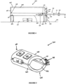
- Figures 3 and 4 illustrates an exemplary system 100 for simulating the insertion of an elongated instrument into a subject.
- the system comprises a medical apparatusmedical or body simulating apparatus 200, an elongated instrument 300, a sensing unit 400, a simulation computer machine 500 and a display unit 600.
- the sensing unit 400 is not configured for determining the longitudinal position of the proximal section of the elongated instrument 300 and the apparatus 200 is configured to measure the position of the distal end of the elongated instrument 300, as described below.
- the apparatus 200 comprises a frame 202 having a generally rectangular shape longitudinally extending between a proximal face 204 and a distal face 206 along a longitudinal axis A.
- the frame 202 further comprises a top face 208 removably secured to a bottom face 210 and defining a closed enclosure.
- the top face 208 may be removably secured to the bottom face 210 via a pair of slides 212 for providing access to the enclosure of the frame 202.
- the top face 208 may be removed from the apparatus 200 by sliding the top face 208 relative to the bottom face 210 along the longitudinal axis A.
- the person skilled in the art will understand that other mounting methods for mounting the top face 208 to the bottom face 210 may be contemplated for providing access to the enclosure.
- the top face 208 may be hinged to the bottom face 210 at a first side and may rotate around the axis of the hinge for providing access to the enclosure of the frame 202.
- the proximal face 204 has a generally rectangular shape and comprises an aperture 214 sized and shaped to receive the elongated instrument 300 therethrough.
- the size of the aperture 214 may substantially correspond to the size of an incision made on a subject during a specific surgical procedure.
- various additional apertures may be provided, on the frame 202, for instance on the distal face 206 or on the top and bottom faces 208 and 210 for power and electronics communication with the simulation machine 500.
- the apparatus is disposed on a plane receiving surface 216 such as a table or a counter.
- a plane receiving surface 216 such as a table or a counter.
- the apparatus 200 may be positioned on a surgical table at an appropriate height from the floor surface for enabling a medical practitioner to train in similar condition as a real surgical procedure on a subject.
- the apparatus 200 further comprises a longitudinal guide rail 218 secured to the bottom face 210 of the frame 202 via support members 220 and 222, and extending along the longitudinal axis A of the apparatus 200 between a first end 224 joining the proximal face 204 and a second end 226 joining the distal face 206.
- the longitudinal guide rail 218 is further configured to be longitudinally aligned with the aperture 214.
- the longitudinal guide rail 218 comprises either a rail, a pair of rails, a channel, a tunnel, or any other type of structure, which can act as a longitudinal guide.
- the apparatus 200 further comprises a carriage 228 slidably mounted onto a longitudinal guide rail 218 for translation therealong.
- the carriage 228 has a base plate 230 configured to slide freely onto the longitudinal guide rail 218 between a first abutting element 232 mounted at the first end 224 of the guide rail 218 and a second abutting element 234 mounted at the second end 226 of the guide rail 218.
- the first and second abutting elements 232 and 234 confine the movement of the carriage 228 along the elongated guide rail 218 within an operational range, i.e. the distance between the first and second abutting elements 232 and 234, corresponding for example to a distance of insertion of the elongated instrument within the subject to reach the organ to be treated for a specific surgical procedure.
- the longitudinal guide rail 218 may comprise a plurality of holes (not shown) equally spaced therealong and sized and shaped to receive the first and second abutting elements 232 and 234. Therefore, according to the type of surgical procedure to be simulated, the operational range may be modified by removably positioning the first and second abutting elements 232 and 234 at different holes of the guide rail 218 to better reflect a given surgical procedure.
- the carriage 228 comprises a face 236 aligned with the aperture 214 for receiving a distal end 304 of the elongated instrument 300 when inserted therethrough.
- the distal end 304 of the elongated instrument 300 is then removably secured to the carriage 228.
- the elongated instrument 300 upon further insertion of the elongated instrument 300 within the apparatus 200 through the aperture 214, the elongated instrument 300 is linearly displaced along the longitudinal guide rail 218 by abutting against the face 236 of the carriage 228.
- the apparatus 200 may further comprise a carriage position sensing element 238 and a linear encoder strip (not shown) mounted along the elongated guide rail 218, and a corresponding optical reader 240 as shown in Figure 4 for example, is used for sensing a longitudinal position of the carriage 228 along the longitudinal guide rail 218 during displacement of the elongated instrument 300.
- a carriage position sensing element 238 and a linear encoder strip (not shown) mounted along the elongated guide rail 218, and a corresponding optical reader 240 as shown in Figure 4 for example, is used for sensing a longitudinal position of the carriage 228 along the longitudinal guide rail 218 during displacement of the elongated instrument 300.
- a corresponding optical reader 240 as shown in Figure 4 for example, is used for sensing a longitudinal position of the carriage 228 along the longitudinal guide rail 218 during displacement of the elongated instrument 300.
- linear position tracking devices may be used for measuring the displacement of the carriage 228, such as an accelerometer, a capacitive transducer, a capac
- the apparatus 200 may further comprise a feedback force actuator (not shown) adapted to apply a resistive force to the longitudinal displacement of the carriage 228 along the guide rail 218 for providing an enhanced and realistic displacement of the elongated instrument 300 when inserted in the apparatus 200.
- the feedback force actuator may for instance comprise a motor (not shown), such as a stepper motor, secured to the carriage 228, a control unit (not shown) and a transmission element (not shown) coupled to the motor and the control unit.
- the feedback force actuator may be controlled by the control unit according to the longitudinal displacement of the carriage 228 and the resistance characteristics of the subject's body. The resistance characteristics of the body are representative of a subject's internal structure into which the elongated instrument 300 is to be inserted.
- These resistance characteristics may be provided by a specific 3D model of a structure of a specific subject and may embed natural movements of a human body like heart beating and breathing. For instance, these characteristics may include tissue resistance during insertion of the elongated instrument 300 within an artery or a vein.
- the resistance characteristics are adjusted by the control unit depending on a given surgical procedure for enabling medical practitioner trainees to train with hands-on conditions substantially similar to real surgery.
- the apparatus 200 further comprises an electronic unit 242 operatively coupled to the carriage position sensing element 238 and the control unit of the feedback actuator.
- the electronic unit 242 comprises a communication unit 244 configured to communicate to the simulation machine 500 the measured displacement values of the carriage 228 as well as the resistance characteristics applied by the control unit.
- the electronic unit 242 of the apparatus 200 is wired to the simulation machine 500 using communication cables.
- the electronic unit 242 is wirelessly connected to the simulation machine 500 using wireless protocols such as WiFi, Bluetooth ® and the like.
- the sensing unit 400 is mounted on the elongated instrument 300.
- the elongated instrument 300 is a medical grade surgical instrument used in minimally invasive procedures.
- the elongated instrument 300 may be a catheter, a lead wire, a delivery tube or a guidewire adapted to be inserted into a subject and displaced through an artery or vein to reach an organ to be treated.
- the elongated instrument 300 may be used for different surgical procedures such as cardiovascular, urological, gastrointestinal, neurovascular, ophthalmic procedures and the like.
- the elongated instrument 300 has a generally elongated shape comprising a tubular body 302 extending longitudinally between a distal end 304 insertable in the apparatus 200 through the aperture 214 and a proximal end 306, located away from the apparatus 200.
- the elongated instrument 300 may further be segmented into a distal section 308 extending from the distal end 304 and configured to be inserted in the apparatus 200 and a proximal section 310 extending from the proximal end 306 and adapted to remain outside of the apparatus 200.
- the distal section 308 corresponds at least to the operational range of displacement of the carriage 228 along the guide rail 218.
- the sensing unit 400 is secured to the proximal section 310 of the elongated member 300. In the present embodiment, the sensing unit 400 is removably secured to the elongated instrument 300.
- the sensing unit 400 may have a generally longitudinal cylindrical shape comprising a first hemi-tubular section 402 and a second hemi-tubular section 404 extending longitudinally between a first end 406 and a second end 408.
- the first hemi-tubular section 402 has a semicircular shape and comprises a first internal surface extending between the first end 406 and the second end 408.
- the second hemi-tubular section 404 has a semicircular shape, similar to the shape of the first hemi-tubular section 402, and comprises a second internal surface 412 extending form the first end 406 to the second end 408.
- the first and second hemi-tubular sections 402 and 404 are hingedly coupled together via a hinge 414 and are adapted to move between an open configuration wherein the first and second hemi-tubular sections 402 and 404 are rotated away from each other and a closed configuration wherein the first and second hemi-tubular sections 402 and 404 are secured together via an attachment member 416 located diametrically away from the hinge 414.
- first and second hemi-tubular sections 402 and 404 may further be coupled together using fasteners.
- the sensing unit 400 is adapted to be tightly clamped on the proximal section 310 of the elongated instrument 300, as shown in Figures 3 and 4 . More precisely, as the sensing unit 400 is clamped on the proximal section 310 of the elongated instrument 300, the first and second internal surfaces 410 and 412 of the first and second hemi-tubular sections 402 and 404 are in friction engagement with the body 302 of the elongated instrument 300 therefore preventing relative movement therebetween.
- the sensing unit 400 comprises an sensor 418, located on either the first or second hemi-tubular sections 402 and 404 and configured to measure the angular position or the rotation angle of the proximal section 310 of the elongated instrument 300.
- the sensor 418 is a gyroscope sensor such as a microelectromechanical system (MEMS) gyro sensor or a 3 axis gyro sensor adapted to measure the angular velocity of the proximal section 310 of the elongated instrument 300 during manipulation by the medical practitioner trainee.
- MEMS microelectromechanical system
- the sensing unit 400 further comprises a communication unit 420 located in either the first or second hemi-tubular sections 402 and 404, and configured to communicate with the simulation machine 500 for transmitting the measured value to the proximal section 310 of the elongated instrument 300 thereto.
- a communication unit 420 located in either the first or second hemi-tubular sections 402 and 404, and configured to communicate with the simulation machine 500 for transmitting the measured value to the proximal section 310 of the elongated instrument 300 thereto.
- the communication unit 420 may communicate with the simulation machine 500 either via wires or wirelessly using communication protocols such as WiFi, Bluetooth ® and the like.
- the sensing unit 400 is clamped to the proximal section 310 of the elongated instrument 300 by securing an attachment member 416 between the first and second hemi-tubular sections 402 and 404.
- the angular position or rotation about its axis of the proximal section 310 of the elongated instrument 300 is continuously measured by the sensing unit 400 and communicated to the simulation machine 500 via the communication unit 420.
- first hemi-tubular section 402 and a second hemi-tubular section 404 are independent form one another.
- the sensing unit is securable to the elongated instrument, any adequate method for removably securing the sensing unit to the elongated instrument may be used.
- the sensing unit may comprise a flexible and elastic tubular body acting as a sleeve or sheath to be positioned over the elongated instrument at an adequate position.
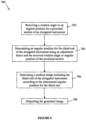
- Figure 6 illustrates one embodiment of a computer-implemented method 700 for simulating the insertion of an elongated medical instrument into a subject.
- the method 700 is performed by a computer machine provided with a processing unit, a memory and communication means.
- the method 700 is performed in collaboration with a medical apparatus in which the distal end of an elongated instrument is inserted, as described above.
- the rotation angle or the angular position of the proximal section of the elongated instrument is received.
- any adequate method for measuring the rotation angle of the proximal section of the elongated instrument about its axis or the angular position of the proximal section may be used.
- the angular position for the distal end of the elongated instrument is determined using an adjustment factor and the measured rotation angle or angular position of the proximal section of the elongated instrument received at step 702, as described above.
- a medical image of a portion of the subject is generated.
- the generated image comprises a representation of at least the distal end of the elongated instrument which is generated according to the angular position determined at step 704.
- the generated image is outputted.
- the generated image may be stored in memory and/or displayed on a display unit.
- the medical apparatus comprises a position tracking device which measures the longitudinal position of the distal end of the elongated instrument within the medical apparatus.
- the method 700 may further comprise a step of receiving the longitudinal position of the distal end of the elongated instrument and the generation of the medical image is performed according to the measured longitudinal position of the distal end of the elongated instrument.
- the method 700 further comprises a step of receiving a longitudinal position or a longitudinal displacement of the proximal section of the elongated instrument and a step of determining the longitudinal position for the distal end of the elongated instrument, as described above.
- the generation of the medical image is performed according to the determined longitudinal position for the distal end of the elongated instrument.
- the tracking of the angular position or rotation angle of the proximal section of the elongated instrument is performed substantially continuously.
- the steps 702-708 are performed substantially continuously to as a provide a real-time simulation.
- FIG. 7 is a block diagram illustrating an exemplary processing module 710 for executing the steps 702 to 708 of the method 10, in accordance with some embodiments.
- the processing module 710 typically includes one or more Computer Processing Units (CPUs) and/or Graphic Processing Units (GPUs) 712 for executing modules or programs and/or instructions stored in memory 714 and thereby performing processing operations, memory 714, and one or more communication buses 716 for interconnecting these components.
- the communication buses 716 optionally include circuitry (sometimes called a chipset) that interconnects and controls communications between system components.
- the memory 714 includes high-speed random access memory, such as DRAM, SRAM, DDR RAM or other random access solid state memory devices, and may include non-volatile memory, such as one or more magnetic disk storage devices, optical disk storage devices, flash memory devices, or other non-volatile solid state storage devices.
- the memory 714 optionally includes one or more storage devices remotely located from the CPU(s) 712.
- the memory 714, or alternately the non-volatile memory device(s) within the memory 714 comprises a non-transitory computer readable storage medium.
- the memory 714, or the computer readable storage medium of the memory 714 stores the following programs, modules, and data structures, or a subset thereof:
- distal longitudinal position module 724 may be omitted.
- Each of the above identified elements may be stored in one or more of the previously mentioned memory devices, and corresponds to a set of instructions for performing a function described above.
- the above identified modules or programs i.e., sets of instructions
- the memory 714 may store a subset of the modules and data structures identified above.
- the memory 714 may store additional modules and data structures not described above.
- Figure 7 is intended more as functional description of the various features which may be present in a management module than as a structural schematic of the embodiments described herein. In practice, and as recognized by those of ordinary skill in the art, items shown separately could be combined and some items could be separated.
Claims (11)
- Système (10) pour simuler une insertion d'un instrument allongé (14) dans le corps d'un sujet, le système comprenant :un appareil médical (12) comprenant un cadre s'étendant entre une face proximale et une face distale le long d'un axe longitudinal, la face proximale étant pourvue d'une ouverture pour recevoir l'instrument allongé (14) à l'intérieur ;une unité de détection (16) qui est configurée pour mesurer une position angulaire réelle ou un angle de rotation pour une section proximale de l'instrument allongé (14), la section proximale de l'instrument allongé (14) se trouvant à l'extérieur de l'appareil médical (12),dans lequel l'unité de détection (16) peut être fixée de manière amovible à la section proximale de l'instrument allongé (14),l'unité de détection (16) comprend au moins un capteur de gyroscope (418) pour mesurer la position angulaire réelle ou l'angle de rotation pour la section proximale de l'instrument allongé (14) ; etune machine de simulation (18) en communication avec l'unité de détection (16) pour recevoir la position angulaire mesurée ou l'angle de rotation mesuré par celle-ci, la machine de simulation (18) comprenant au moins une unité de traitement (20) configurée pour :calculer une position angulaire distale pour une extrémité distale (26) de l'instrument allongé (14) en utilisant un facteur de réglage et la position angulaire réelle ou l'angle de rotation pour la section proximale de l'instrument allongé (14), le facteur de réglage étant choisi de manière à simuler une torsion de l'instrument allongé (14) entre sa section proximale et sa section distale, et dans lequel le facteur de réglage varie en fonction d'une position de l'extrémité distale de l'instrument allongé à l'intérieur de l'appareil médical ou en fonction d'une longueur d'une partie de l'instrument allongé inséré dans l'appareil médical ;générer une image médicale d'au moins une partie du corps du sujet, l'image médicale comprenant au moins une représentation d'une section distale de l'instrument allongé (14), la représentation de la section distale étant générée selon la position angulaire distale ; etdélivrer l'image médicale générée.
- Système (10) selon la revendication 1, dans lequel l'unité de détection (16) est adaptée pour mesurer la position angulaire réelle de la section proximale de l'instrument allongé (14), l'unité de traitement (20) étant en outre configurée pour déterminer l'angle de rotation sur la base de la position angulaire réelle et d'une position angulaire initiale.
- Système (10) selon l'une quelconque des revendications 1 ou 2, dans lequel l'unité de détection (16) est en outre configurée pour mesurer une position longitudinale réelle ou un déplacement longitudinal pour la section proximale de l'instrument allongé (14), l'unité de traitement (20) étant en outre configurée pour :calculer une position longitudinale distale pour l'extrémité distale (26) de l'instrument allongé (14) en utilisant un facteur de correction et la position longitudinale réelle ou le déplacement longitudinal pour la section proximale de l'instrument allongé (14), le facteur de correction étant choisi de manière à simuler une flexion de l'instrument allongé (14) entre sa section proximale et sa section distale ; etgénérer l'image médicale en tenant compte de la position longitudinale distale pour l'extrémité distale (26) de l'instrument allongé (14).
- Système (10) selon la revendication 3, dans lequel l'unité de détection (16) est configurée pour mesurer la position longitudinale réelle de la section proximale de l'instrument allongé (14), et l'unité de traitement (20) est en outre configurée pour déterminer le déplacement longitudinal pour la section proximale de l'instrument allongé (14) en utilisant la position longitudinale réelle et une position longitudinale initiale pour la section proximale de l'instrument allongé (14).
- Système (10) selon la revendication 3 ou 4, dans lequel l'unité de détection (16) comprend en outre au moins un accéléromètre pour mesurer la position longitudinale réelle ou le déplacement longitudinal pour la section proximale de l'instrument allongé (14).
- Système (10) selon l'une quelconque des revendications 3 à 5, dans lequel le facteur de correction varie en fonction d'une position de l'extrémité distale (26) de l'instrument allongé (14) à l'intérieur de l'appareil médical (12).
- Procédé mis en oeuvre par ordinateur pour simuler une insertion d'un instrument allongé (14) dans le corps d'un sujet, le procédé comprenant :la réception d'une position angulaire réelle ou un angle de rotation pour une section proximale de l'instrument allongé (14), dans lequel la position angulaire réelle ou l'angle de rotation est reçu(e) d'une unité de détection (16) pouvant être fixée de manière amovible à la section proximale de l'instrument allongé (14), dans lequel l'unité de détection (16) comprend au moins un capteur de gyroscope (418) pour mesurer la position angulaire réelle ou l'angle de rotation pour la section proximale de l'instrument allongé (14), au moins une extrémité distale (26) de l'instrument allongé (14) étant insérée dans un appareil médical (12) ;la détermination d'une position angulaire distale pour l'extrémité distale (26) de l'instrument allongé (14) inséré dans l'appareil médical (12) en utilisant un facteur de réglage et la position angulaire réelle ou l'angle de rotation pour la section proximale de l'instrument allongé (14), le facteur de réglage étant choisi de manière à simuler une torsion de l'instrument allongé (14) entre sa section proximale et sa section distale lorsque la position angulaire réelle est mesurée, et dans lequel le facteur de réglage varie en fonction d'une position de l'extrémité distale de l'instrument allongé à l'intérieur de l'appareil médical ou en fonction d'une longueur d'une partie de l'instrument allongé inséré dans l'appareil médical ;la génération d'une image médicale d'au moins une partie du corps du sujet, l'image médicale comprenant au moins une représentation d'une section distale de l'instrument allongé (14), la représentation de la section distale étant générée selon la position angulaire distale ; etla sortie de l'image médicale générée.
- Procédé mis en oeuvre par ordinateur selon la revendication 7, dans lequel ladite réception de la position angulaire réelle ou de l'angle de rotation comprend la réception de la position angulaire réelle de la section proximale de l'instrument allongé (14), le procédé comprenant en outre la détermination de l'angle de rotation en utilisant la position angulaire réelle et une position angulaire initiale pour la section proximale de l'instrument allongé (14).
- Procédé mis en oeuvre par ordinateur selon la revendication 7 ou 8, comprenant en outre la réception d'une position longitudinale réelle ou d'un déplacement longitudinal pour la section proximale de l'instrument allongé (14), et le calcul d'une position longitudinale distale pour l'extrémité distale (26) de l'instrument allongé (14) en utilisant un facteur de correction et la position longitudinale réelle ou le déplacement longitudinal pour la section proximale de l'instrument allongé (14), le facteur de correction étant choisi de manière à introduire une flexion de l'instrument allongé (14) entre sa section proximale et sa section distale ; ladite génération de l'image médicale étant réalisée en tenant compte de la position longitudinale distale pour l'extrémité distale (26) de l'instrument allongé (14).
- Procédé mis en oeuvre par ordinateur selon la revendication 9, dans lequel ladite réception de la position longitudinale réelle ou du déplacement longitudinal comprend la réception de la position longitudinale réelle, le procédé mis en oeuvre par ordinateur comprenant en outre la détermination du déplacement longitudinal pour la section proximale de l'instrument allongé (14) en utilisant la position longitudinale réelle et une position longitudinale initiale pour la section proximale de l'instrument allongé (14).
- Procédé mis en oeuvre par ordinateur selon la revendication 9 ou 10, dans lequel ladite réception de la position longitudinale réelle ou du déplacement longitudinal comprend la réception d'au moins une valeur d'accélération, le procédé mis en oeuvre par ordinateur comprenant en outre la détermination de la position longitudinale réelle ou du déplacement longitudinal à partir de l'au moins une valeur d'accélération.
Applications Claiming Priority (2)
| Application Number | Priority Date | Filing Date | Title |
|---|---|---|---|
| CA3000164A CA3000164C (fr) | 2018-03-29 | 2018-03-29 | Methode et systeme de simulation d'une insertion d'un instrument allonge dans un sujet |
| US15/976,047 US11501661B2 (en) | 2018-03-29 | 2018-05-10 | Method and system for simulating an insertion of an elongated instrument into a subject |
Publications (2)
| Publication Number | Publication Date |
|---|---|
| EP3547296A1 EP3547296A1 (fr) | 2019-10-02 |
| EP3547296B1 true EP3547296B1 (fr) | 2023-02-22 |
Family
ID=66239732
Family Applications (1)
| Application Number | Title | Priority Date | Filing Date |
|---|---|---|---|
| EP19165720.4A Active EP3547296B1 (fr) | 2018-03-29 | 2019-03-28 | Méthode et système pour la simulation d'introduire un instrument oblong dans un sujet d'expérience |
Country Status (4)
| Country | Link |
|---|---|
| US (1) | US11501661B2 (fr) |
| EP (1) | EP3547296B1 (fr) |
| JP (1) | JP6721748B2 (fr) |
| CN (1) | CN110322966B (fr) |
Families Citing this family (2)
| Publication number | Priority date | Publication date | Assignee | Title |
|---|---|---|---|---|
| CN117241756A (zh) | 2021-05-20 | 2023-12-15 | 朝日英达科株式会社 | 医疗系统以及导航方法 |
| CA3149196C (fr) | 2022-02-17 | 2024-03-05 | Cae Healthcare Canada Inc. | Methode et systeme de production d'une image medicale simulee |
Citations (1)
| Publication number | Priority date | Publication date | Assignee | Title |
|---|---|---|---|---|
| CA2921848C (fr) * | 2016-02-26 | 2017-07-18 | Cae Healthcare Canada Inc. | Appareil de simulation d'insertion d'un instrument allonge dans une structure et un simulateur d'insertion medical |
Family Cites Families (31)
| Publication number | Priority date | Publication date | Assignee | Title |
|---|---|---|---|---|
| US4907973A (en) * | 1988-11-14 | 1990-03-13 | Hon David C | Expert system simulator for modeling realistic internal environments and performance |
| US6024576A (en) * | 1996-09-06 | 2000-02-15 | Immersion Corporation | Hemispherical, high bandwidth mechanical interface for computer systems |
| GB2349730B (en) | 1998-01-28 | 2003-04-09 | Ht Medical Systems Inc | Interface device and method for interfacing instruments to medical procedure simulation system |
| US6939138B2 (en) * | 2000-04-12 | 2005-09-06 | Simbionix Ltd. | Endoscopic tutorial system for urology |
| DE10055292B4 (de) * | 2000-11-03 | 2004-02-12 | Karl Storz Gmbh & Co. Kg | Simulatorvorrichtung mit zumindest zwei Bewegungsfreiheitsgraden für die Verwendung bei einem realen Instrument |
| GB2380594B (en) * | 2001-10-02 | 2004-02-04 | Keymed | Improvements in endoscopy training apparatus |
| AU2003283930A1 (en) * | 2002-12-03 | 2004-06-23 | Mentice Ab | An interventional simulation device |
| US20070166682A1 (en) * | 2003-01-22 | 2007-07-19 | Realsim Systems, Llc. | Medical training apparatus |
| US7144378B2 (en) | 2003-10-31 | 2006-12-05 | Arnott Richard J | Quick-release torquer apparatus for delivering and maintaining a medical guideware |
| US8216255B2 (en) | 2004-06-14 | 2012-07-10 | Ethicon Endo-Surgery, Inc. | Endoscopic clip applier actuator |
| EP1903537A3 (fr) * | 2005-07-20 | 2008-06-11 | Richstone Consulting LLC | Système et procédé de simulation d'une opération d'intervention manuelle par un utilisateur dans une procédure médicale |
| US20070134637A1 (en) | 2005-12-08 | 2007-06-14 | Simbionix Ltd. | Medical simulation device with motion detector |
| US20090076417A1 (en) | 2007-08-08 | 2009-03-19 | Gregory Allen Jones | Glide Clip |
| US20100234873A1 (en) | 2007-11-27 | 2010-09-16 | Yoshitaka Nagano | Drive device, and medical apparatus and training apparatus including the same |
| CN201215653Y (zh) * | 2008-01-07 | 2009-04-01 | 陈为坚 | 一种立体定位式鼠标器 |
| US20090263775A1 (en) | 2008-04-22 | 2009-10-22 | Immersion Medical | Systems and Methods for Surgical Simulation and Training |
| US20100100103A1 (en) | 2008-09-15 | 2010-04-22 | Elcam Agricultural Cooperative Association Ltd. | Torque device with side attachment |
| EP2467842B1 (fr) | 2009-08-18 | 2017-10-11 | Airway Limited | Simulateur d'endoscope |
| US9084558B2 (en) | 2011-02-07 | 2015-07-21 | Syntervention, Inc. | Angular rotation guidance device for a surgical instrument |
| US8974401B2 (en) | 2011-02-24 | 2015-03-10 | Syntervention, Inc. | Helical clip and method of using the same |
| US9439653B2 (en) | 2011-12-07 | 2016-09-13 | Traumatek Solutions B.V. | Devices and methods for endovascular access and therapy |
| WO2014010177A1 (fr) | 2012-07-10 | 2014-01-16 | パナソニック株式会社 | Dispositif de mesure de force, procédé de mesure de force, dispositif maître/esclave, programme de mesure de force, et circuit électronique intégré |
| JP2016501655A (ja) | 2012-12-31 | 2016-01-21 | クリアストリーム・テクノロジーズ・リミテッド | 位置合わせを容易にするためのマーキングを有するカテーテル |
| JP5788623B2 (ja) * | 2013-07-12 | 2015-10-07 | オリンパス株式会社 | 内視鏡システム |
| US20150086958A1 (en) * | 2013-09-25 | 2015-03-26 | University Of Delaware | Medical treatment simulation devices |
| US9922578B2 (en) * | 2014-01-17 | 2018-03-20 | Truinject Corp. | Injection site training system |
| SG10202007098SA (en) | 2014-04-18 | 2020-08-28 | Becton Dickinson Co | Needle capture safety interlock for catheter |
| EP3209217A4 (fr) | 2014-10-22 | 2018-06-27 | Merit Medical Systems, Inc. | Dispositif de couple et mécanisme de fixation |
| KR102542190B1 (ko) * | 2015-04-06 | 2023-06-12 | 인튜어티브 서지컬 오퍼레이션즈 인코포레이티드 | 영상 안내 수술에서의 정합 보상의 시스템 및 방법 |
| CN109715037B (zh) * | 2016-09-21 | 2022-09-06 | 直观外科手术操作公司 | 用于器械弯折检测的系统和方法 |
| SG10201700386PA (en) * | 2017-01-17 | 2018-08-30 | Ndr Medical Tech Pte Ltd | A System And Method For Aligning An Elongated Tool To An Occluded Target |
-
2018
- 2018-05-10 US US15/976,047 patent/US11501661B2/en active Active
-
2019
- 2019-03-28 JP JP2019063482A patent/JP6721748B2/ja active Active
- 2019-03-28 EP EP19165720.4A patent/EP3547296B1/fr active Active
- 2019-03-29 CN CN201910249518.1A patent/CN110322966B/zh active Active
Patent Citations (1)
| Publication number | Priority date | Publication date | Assignee | Title |
|---|---|---|---|---|
| CA2921848C (fr) * | 2016-02-26 | 2017-07-18 | Cae Healthcare Canada Inc. | Appareil de simulation d'insertion d'un instrument allonge dans une structure et un simulateur d'insertion medical |
Also Published As
| Publication number | Publication date |
|---|---|
| US20190304344A1 (en) | 2019-10-03 |
| JP2019171074A (ja) | 2019-10-10 |
| CN110322966A (zh) | 2019-10-11 |
| JP6721748B2 (ja) | 2020-07-15 |
| CN110322966B (zh) | 2021-11-23 |
| US11501661B2 (en) | 2022-11-15 |
| EP3547296A1 (fr) | 2019-10-02 |
Similar Documents
| Publication | Publication Date | Title |
|---|---|---|
| KR102444865B1 (ko) | 복강경 트레이닝 시스템 | |
| US8480406B2 (en) | Interface device and method for interfacing instruments to medical procedure simulation systems | |
| EP1103041B1 (fr) | Procede et dispositif d'interface entre des instruments et un systeme de simulation de procedure medicale | |
| EP2439719A1 (fr) | Simulation d'une procédure invasive | |
| RU2621414C2 (ru) | Система для имитации медицинской процедуры с визуализационным контролем, способ управления системой для имитации медицинской процедуры и рабочий блок системы для имитации | |
| WO2018218175A1 (fr) | Système de formation laparoscopique | |
| EP3547296B1 (fr) | Méthode et système pour la simulation d'introduire un instrument oblong dans un sujet d'expérience | |
| CA3000164C (fr) | Methode et systeme de simulation d'une insertion d'un instrument allonge dans un sujet | |
| CA2921848C (fr) | Appareil de simulation d'insertion d'un instrument allonge dans une structure et un simulateur d'insertion medical | |
| Trantakis et al. | “IOMaster 7D”—a new device for virtual neuroendoscopy | |
| CA2921855C (fr) | Appareil de simulation d'insertion d'un instrument allonge dans une structure et un simulateur d'insertion medical | |
| US20170249867A1 (en) | Apparatus for simulating insertion of an elongated instrument into a structure including a pulley and a pulley position sensing arrangement | |
| CN114430847A (zh) | 多工具医学模拟系统和方法 | |
| GB2384613A (en) | Interfacing medical instruments with medical simulations systems. |
Legal Events
| Date | Code | Title | Description |
|---|---|---|---|
| PUAI | Public reference made under article 153(3) epc to a published international application that has entered the european phase |
Free format text: ORIGINAL CODE: 0009012 |
|
| STAA | Information on the status of an ep patent application or granted ep patent |
Free format text: STATUS: THE APPLICATION HAS BEEN PUBLISHED |
|
| AK | Designated contracting states |
Kind code of ref document: A1 Designated state(s): AL AT BE BG CH CY CZ DE DK EE ES FI FR GB GR HR HU IE IS IT LI LT LU LV MC MK MT NL NO PL PT RO RS SE SI SK SM TR |
|
| AX | Request for extension of the european patent |
Extension state: BA ME |
|
| STAA | Information on the status of an ep patent application or granted ep patent |
Free format text: STATUS: REQUEST FOR EXAMINATION WAS MADE |
|
| 17P | Request for examination filed |
Effective date: 20200228 |
|
| RBV | Designated contracting states (corrected) |
Designated state(s): AL AT BE BG CH CY CZ DE DK EE ES FI FR GB GR HR HU IE IS IT LI LT LU LV MC MK MT NL NO PL PT RO RS SE SI SK SM TR |
|
| STAA | Information on the status of an ep patent application or granted ep patent |
Free format text: STATUS: EXAMINATION IS IN PROGRESS |
|
| 17Q | First examination report despatched |
Effective date: 20210706 |
|
| GRAP | Despatch of communication of intention to grant a patent |
Free format text: ORIGINAL CODE: EPIDOSNIGR1 |
|
| STAA | Information on the status of an ep patent application or granted ep patent |
Free format text: STATUS: GRANT OF PATENT IS INTENDED |
|
| GRAS | Grant fee paid |
Free format text: ORIGINAL CODE: EPIDOSNIGR3 |
|
| INTG | Intention to grant announced |
Effective date: 20221215 |
|
| GRAA | (expected) grant |
Free format text: ORIGINAL CODE: 0009210 |
|
| STAA | Information on the status of an ep patent application or granted ep patent |
Free format text: STATUS: THE PATENT HAS BEEN GRANTED |
|
| AK | Designated contracting states |
Kind code of ref document: B1 Designated state(s): AL AT BE BG CH CY CZ DE DK EE ES FI FR GB GR HR HU IE IS IT LI LT LU LV MC MK MT NL NO PL PT RO RS SE SI SK SM TR |
|
| REG | Reference to a national code |
Ref country code: GB Ref legal event code: FG4D |
|
| REG | Reference to a national code |
Ref country code: CH Ref legal event code: EP |
|
| REG | Reference to a national code |
Ref country code: AT Ref legal event code: REF Ref document number: 1550017 Country of ref document: AT Kind code of ref document: T Effective date: 20230315 Ref country code: IE Ref legal event code: FG4D |
|
| REG | Reference to a national code |
Ref country code: DE Ref legal event code: R096 Ref document number: 602019025428 Country of ref document: DE |
|
| PGFP | Annual fee paid to national office [announced via postgrant information from national office to epo] |
Ref country code: FR Payment date: 20230308 Year of fee payment: 5 |
|
| REG | Reference to a national code |
Ref country code: LT Ref legal event code: MG9D |
|
| REG | Reference to a national code |
Ref country code: NL Ref legal event code: MP Effective date: 20230222 |
|
| REG | Reference to a national code |
Ref country code: AT Ref legal event code: MK05 Ref document number: 1550017 Country of ref document: AT Kind code of ref document: T Effective date: 20230222 |
|
| PG25 | Lapsed in a contracting state [announced via postgrant information from national office to epo] |
Ref country code: RS Free format text: LAPSE BECAUSE OF FAILURE TO SUBMIT A TRANSLATION OF THE DESCRIPTION OR TO PAY THE FEE WITHIN THE PRESCRIBED TIME-LIMIT Effective date: 20230222 Ref country code: PT Free format text: LAPSE BECAUSE OF FAILURE TO SUBMIT A TRANSLATION OF THE DESCRIPTION OR TO PAY THE FEE WITHIN THE PRESCRIBED TIME-LIMIT Effective date: 20230622 Ref country code: NO Free format text: LAPSE BECAUSE OF FAILURE TO SUBMIT A TRANSLATION OF THE DESCRIPTION OR TO PAY THE FEE WITHIN THE PRESCRIBED TIME-LIMIT Effective date: 20230522 Ref country code: NL Free format text: LAPSE BECAUSE OF FAILURE TO SUBMIT A TRANSLATION OF THE DESCRIPTION OR TO PAY THE FEE WITHIN THE PRESCRIBED TIME-LIMIT Effective date: 20230222 Ref country code: LV Free format text: LAPSE BECAUSE OF FAILURE TO SUBMIT A TRANSLATION OF THE DESCRIPTION OR TO PAY THE FEE WITHIN THE PRESCRIBED TIME-LIMIT Effective date: 20230222 Ref country code: LT Free format text: LAPSE BECAUSE OF FAILURE TO SUBMIT A TRANSLATION OF THE DESCRIPTION OR TO PAY THE FEE WITHIN THE PRESCRIBED TIME-LIMIT Effective date: 20230222 Ref country code: HR Free format text: LAPSE BECAUSE OF FAILURE TO SUBMIT A TRANSLATION OF THE DESCRIPTION OR TO PAY THE FEE WITHIN THE PRESCRIBED TIME-LIMIT Effective date: 20230222 Ref country code: ES Free format text: LAPSE BECAUSE OF FAILURE TO SUBMIT A TRANSLATION OF THE DESCRIPTION OR TO PAY THE FEE WITHIN THE PRESCRIBED TIME-LIMIT Effective date: 20230222 Ref country code: AT Free format text: LAPSE BECAUSE OF FAILURE TO SUBMIT A TRANSLATION OF THE DESCRIPTION OR TO PAY THE FEE WITHIN THE PRESCRIBED TIME-LIMIT Effective date: 20230222 |
|
| PGFP | Annual fee paid to national office [announced via postgrant information from national office to epo] |
Ref country code: DE Payment date: 20230412 Year of fee payment: 5 |
|
| PG25 | Lapsed in a contracting state [announced via postgrant information from national office to epo] |
Ref country code: SE Free format text: LAPSE BECAUSE OF FAILURE TO SUBMIT A TRANSLATION OF THE DESCRIPTION OR TO PAY THE FEE WITHIN THE PRESCRIBED TIME-LIMIT Effective date: 20230222 Ref country code: PL Free format text: LAPSE BECAUSE OF FAILURE TO SUBMIT A TRANSLATION OF THE DESCRIPTION OR TO PAY THE FEE WITHIN THE PRESCRIBED TIME-LIMIT Effective date: 20230222 Ref country code: IS Free format text: LAPSE BECAUSE OF FAILURE TO SUBMIT A TRANSLATION OF THE DESCRIPTION OR TO PAY THE FEE WITHIN THE PRESCRIBED TIME-LIMIT Effective date: 20230622 Ref country code: GR Free format text: LAPSE BECAUSE OF FAILURE TO SUBMIT A TRANSLATION OF THE DESCRIPTION OR TO PAY THE FEE WITHIN THE PRESCRIBED TIME-LIMIT Effective date: 20230523 Ref country code: FI Free format text: LAPSE BECAUSE OF FAILURE TO SUBMIT A TRANSLATION OF THE DESCRIPTION OR TO PAY THE FEE WITHIN THE PRESCRIBED TIME-LIMIT Effective date: 20230222 |
|
| PG25 | Lapsed in a contracting state [announced via postgrant information from national office to epo] |
Ref country code: SM Free format text: LAPSE BECAUSE OF FAILURE TO SUBMIT A TRANSLATION OF THE DESCRIPTION OR TO PAY THE FEE WITHIN THE PRESCRIBED TIME-LIMIT Effective date: 20230222 Ref country code: RO Free format text: LAPSE BECAUSE OF FAILURE TO SUBMIT A TRANSLATION OF THE DESCRIPTION OR TO PAY THE FEE WITHIN THE PRESCRIBED TIME-LIMIT Effective date: 20230222 Ref country code: EE Free format text: LAPSE BECAUSE OF FAILURE TO SUBMIT A TRANSLATION OF THE DESCRIPTION OR TO PAY THE FEE WITHIN THE PRESCRIBED TIME-LIMIT Effective date: 20230222 Ref country code: DK Free format text: LAPSE BECAUSE OF FAILURE TO SUBMIT A TRANSLATION OF THE DESCRIPTION OR TO PAY THE FEE WITHIN THE PRESCRIBED TIME-LIMIT Effective date: 20230222 Ref country code: CZ Free format text: LAPSE BECAUSE OF FAILURE TO SUBMIT A TRANSLATION OF THE DESCRIPTION OR TO PAY THE FEE WITHIN THE PRESCRIBED TIME-LIMIT Effective date: 20230222 |
|
| PGFP | Annual fee paid to national office [announced via postgrant information from national office to epo] |
Ref country code: GB Payment date: 20230424 Year of fee payment: 5 |
|
| REG | Reference to a national code |
Ref country code: CH Ref legal event code: PL |
|
| REG | Reference to a national code |
Ref country code: DE Ref legal event code: R097 Ref document number: 602019025428 Country of ref document: DE |
|
| PG25 | Lapsed in a contracting state [announced via postgrant information from national office to epo] |
Ref country code: SK Free format text: LAPSE BECAUSE OF FAILURE TO SUBMIT A TRANSLATION OF THE DESCRIPTION OR TO PAY THE FEE WITHIN THE PRESCRIBED TIME-LIMIT Effective date: 20230222 |
|
| REG | Reference to a national code |
Ref country code: BE Ref legal event code: MM Effective date: 20230331 |
|
| PG25 | Lapsed in a contracting state [announced via postgrant information from national office to epo] |
Ref country code: LU Free format text: LAPSE BECAUSE OF NON-PAYMENT OF DUE FEES Effective date: 20230328 |
|
| PLBE | No opposition filed within time limit |
Free format text: ORIGINAL CODE: 0009261 |
|
| STAA | Information on the status of an ep patent application or granted ep patent |
Free format text: STATUS: NO OPPOSITION FILED WITHIN TIME LIMIT |
|
| PG25 | Lapsed in a contracting state [announced via postgrant information from national office to epo] |
Ref country code: MC Free format text: LAPSE BECAUSE OF FAILURE TO SUBMIT A TRANSLATION OF THE DESCRIPTION OR TO PAY THE FEE WITHIN THE PRESCRIBED TIME-LIMIT Effective date: 20230222 |
|
| REG | Reference to a national code |
Ref country code: IE Ref legal event code: MM4A |
|
| 26N | No opposition filed |
Effective date: 20231123 |
|
| PG25 | Lapsed in a contracting state [announced via postgrant information from national office to epo] |
Ref country code: SI Free format text: LAPSE BECAUSE OF FAILURE TO SUBMIT A TRANSLATION OF THE DESCRIPTION OR TO PAY THE FEE WITHIN THE PRESCRIBED TIME-LIMIT Effective date: 20230222 Ref country code: MC Free format text: LAPSE BECAUSE OF FAILURE TO SUBMIT A TRANSLATION OF THE DESCRIPTION OR TO PAY THE FEE WITHIN THE PRESCRIBED TIME-LIMIT Effective date: 20230222 Ref country code: LI Free format text: LAPSE BECAUSE OF NON-PAYMENT OF DUE FEES Effective date: 20230331 Ref country code: IE Free format text: LAPSE BECAUSE OF NON-PAYMENT OF DUE FEES Effective date: 20230328 Ref country code: CH Free format text: LAPSE BECAUSE OF NON-PAYMENT OF DUE FEES Effective date: 20230331 |
|
| PG25 | Lapsed in a contracting state [announced via postgrant information from national office to epo] |
Ref country code: BE Free format text: LAPSE BECAUSE OF NON-PAYMENT OF DUE FEES Effective date: 20230331 |