EP3547045A1 - Mécanisme de transmission d'horlogerie à effort d'embrayage réduit - Google Patents
Mécanisme de transmission d'horlogerie à effort d'embrayage réduit Download PDFInfo
- Publication number
- EP3547045A1 EP3547045A1 EP18163966.7A EP18163966A EP3547045A1 EP 3547045 A1 EP3547045 A1 EP 3547045A1 EP 18163966 A EP18163966 A EP 18163966A EP 3547045 A1 EP3547045 A1 EP 3547045A1
- Authority
- EP
- European Patent Office
- Prior art keywords
- mobile
- transmission mechanism
- differential
- satellite
- wheel
- Prior art date
- Legal status (The legal status is an assumption and is not a legal conclusion. Google has not performed a legal analysis and makes no representation as to the accuracy of the status listed.)
- Granted
Links
Images


Classifications
-
- G—PHYSICS
- G04—HOROLOGY
- G04F—TIME-INTERVAL MEASURING
- G04F7/00—Apparatus for measuring unknown time intervals by non-electric means
- G04F7/04—Apparatus for measuring unknown time intervals by non-electric means using a mechanical oscillator
- G04F7/08—Watches or clocks with stop devices, e.g. chronograph
- G04F7/0866—Special arrangements
- G04F7/0871—Special arrangements with multiple chronograph functions, i.e. to count multiple running times
-
- G—PHYSICS
- G04—HOROLOGY
- G04B—MECHANICALLY-DRIVEN CLOCKS OR WATCHES; MECHANICAL PARTS OF CLOCKS OR WATCHES IN GENERAL; TIME PIECES USING THE POSITION OF THE SUN, MOON OR STARS
- G04B19/00—Indicating the time by visual means
- G04B19/02—Back-gearing arrangements between gear train and hands
-
- G—PHYSICS
- G04—HOROLOGY
- G04B—MECHANICALLY-DRIVEN CLOCKS OR WATCHES; MECHANICAL PARTS OF CLOCKS OR WATCHES IN GENERAL; TIME PIECES USING THE POSITION OF THE SUN, MOON OR STARS
- G04B13/00—Gearwork
- G04B13/007—Gearwork with differential work
-
- G—PHYSICS
- G04—HOROLOGY
- G04B—MECHANICALLY-DRIVEN CLOCKS OR WATCHES; MECHANICAL PARTS OF CLOCKS OR WATCHES IN GENERAL; TIME PIECES USING THE POSITION OF THE SUN, MOON OR STARS
- G04B13/00—Gearwork
- G04B13/007—Gearwork with differential work
- G04B13/008—Differentials
-
- G—PHYSICS
- G04—HOROLOGY
- G04B—MECHANICALLY-DRIVEN CLOCKS OR WATCHES; MECHANICAL PARTS OF CLOCKS OR WATCHES IN GENERAL; TIME PIECES USING THE POSITION OF THE SUN, MOON OR STARS
- G04B13/00—Gearwork
- G04B13/02—Wheels; Pinions; Spindles; Pivots
-
- G—PHYSICS
- G04—HOROLOGY
- G04B—MECHANICALLY-DRIVEN CLOCKS OR WATCHES; MECHANICAL PARTS OF CLOCKS OR WATCHES IN GENERAL; TIME PIECES USING THE POSITION OF THE SUN, MOON OR STARS
- G04B27/00—Mechanical devices for setting the time indicating means
- G04B27/02—Mechanical devices for setting the time indicating means by making use of the winding means
- G04B27/06—Mechanical devices for setting the time indicating means by making use of the winding means with rocking bar
- G04B27/065—Changing the winding position to the setting position and vice versa is done with an independant part of the winding or setting mechanism
-
- G—PHYSICS
- G04—HOROLOGY
- G04B—MECHANICALLY-DRIVEN CLOCKS OR WATCHES; MECHANICAL PARTS OF CLOCKS OR WATCHES IN GENERAL; TIME PIECES USING THE POSITION OF THE SUN, MOON OR STARS
- G04B3/00—Normal winding of clockworks by hand or mechanically; Winding up several mainsprings or driving weights simultaneously
- G04B3/06—Keys or the like with means preventing overwinding
-
- G—PHYSICS
- G04—HOROLOGY
- G04F—TIME-INTERVAL MEASURING
- G04F7/00—Apparatus for measuring unknown time intervals by non-electric means
- G04F7/04—Apparatus for measuring unknown time intervals by non-electric means using a mechanical oscillator
- G04F7/08—Watches or clocks with stop devices, e.g. chronograph
- G04F7/0842—Watches or clocks with stop devices, e.g. chronograph with start-stop control mechanisms
- G04F7/0861—Watches or clocks with stop devices, e.g. chronograph with start-stop control mechanisms actuated by other than push-buttons, e.g. bezel or lever
Definitions
- the invention relates to a clock transmission mechanism, arranged to be integrated in a watch movement and comprising at least one differential mechanism comprising at least one satellite mobile mounted crazy pivoting and at least three main mobiles constituting inputs or outputs of said differential mechanism, which three main mobiles are constituted by a frame, a first mobile arranged to cooperate with a first wheel, and a second mobile arranged to cooperate with a second wheel, one of said three main movers being a carrier of at least one said mobile satellite permanently meshing with the other two main mobiles, either directly or through at least one intermediate mobile which meshes permanently with one of said two other main mobiles or which is integral in rotation with the one of said two other main mobiles, said differential mechanism being able to connect cinematics said first mobile and said second mobile in a clutch position, and to dissociate kinematically in a disengaged position.
- the invention also relates to a watch movement comprising at least one such transmission mechanism.
- the invention also relates to a timepiece, in particular a watch, comprising at least one such movement, and / or comprising at least one such transmission mechanism.
- the invention also relates to a watch movement comprising at least one such transmission mechanism.
- the invention relates to the field of mechanical clockwork mechanisms.
- the clutch function has often been used: In a winding mechanism and time setting for example, the sliding pinion makes it possible to perform this clutch function and clutch during the passage of the ring from the T1 position (winding) to the T2 position (time setting ), and vice versa when returning the ring from position T2 to position T1.
- the clutch is double because the reassembly disengages while the time setting is engaged, and vice versa.
- the Start-Stop function (or on / off) is provided by a clutch mechanism (Start) and clutch (Stop).
- the chronograph clutch can be radial by meshing / disengaging the two-wheel teeth that are moved closer to one another. It can also be axial, or vertical, when two coaxially rotating wheels are held in contact by a spring, or kept apart by a fork system.
- the invention proposes to provide an alternative solution to the mechanisms mentioned above, and which limits the number of moving components to perform the clutch and disengagement functions.
- the invention relates to a clock transmission mechanism according to claim 1.
- the invention also relates to a watch movement comprising at least one such transmission mechanism.
- the invention also relates to a timepiece, in particular a watch, comprising at least one such movement, and / or comprising at least one such transmission mechanism.
- the invention relates to a 100 clock transmission mechanism, arranged to be integrated in a watch movement 500, and comprising at least one differential mechanism 10.
- This differential mechanism 10 comprises at least one satellite mobile 3, which is mounted pivotally, and at least three main mobiles constituting inputs or outputs of the differential mechanism 10.
- These three main mobiles are constituted by a frame 60, a first mobile 1 arranged to cooperate with a first wheel, and a second wheel 2 arranged to cooperate with a second wheel. Only one of these three main mobiles carries at least one such satellite mobile 3 permanently meshing with the other two main mobiles, either directly or through at least one intermediate mobile 8 which meshes permanently with the one of the other two main mobiles, or which is integral in rotation with one of the other two main mobiles.
- This differential mechanism 10 is able to kinematically connect the first mobile 1 and the second mobile 2 in a clutch position, and to disengage them kinematically in a disengaged position.
- the transmission mechanism 100 further comprises control means 20, which are arranged to block only one of these three main mobiles, to achieve the clutch of the differential mechanism 10, or to fully release the chassis 60 and the first mobile 1 and the second mobile 2 to disengaging the differential mechanism 10, according to the position printed on the control means 20 by a selector 30 that comprises the transmission mechanism 100 and which is arranged to cooperate with an actuator that includes a watch movement 500, and / or for be operated by a user, or even to both cooperate with such an actuator and be operable by a user.
- control means 20 which are arranged to block only one of these three main mobiles, to achieve the clutch of the differential mechanism 10, or to fully release the chassis 60 and the first mobile 1 and the second mobile 2 to disengaging the differential mechanism 10, according to the position printed on the control means 20 by a selector 30 that comprises the transmission mechanism 100 and which is arranged to cooperate with an actuator that includes a watch movement 500, and / or for be operated by a user, or even to both cooperate with such an actuator and be operable by a user.
- control means 20 are returned to a blocking mobile.
- This blocking mobile is that of the three main mobiles on which is made the locking of the differential mechanism 10 in the clutch position, by elastic return means 40, which are arranged to exert on the locking mobile a pair of meshing or friction, whose setting allows a safety clutch when the torque transmitted from one to the other of the other main mobile, which does not constitute the mobile blocking, is greater than the meshing or friction torque.
- this selector 30 comprises at least one column wheel 31, which is arranged for, according to its angular position, modify the angular position of a rocker 21 that comprises the control means 20.
- flip-flop 21 has a first spout 22 which is arranged to immobilize or release, depending on its position, a peripheral toothing that includes the locking mobile.
- the locking wheel has an external teeth with wolf teeth, so as to allow a safety release in a direction of rotation.
- the transmission mechanism 100 further comprises mechanical locking means 50, which are arranged to be operated by an actuator that includes a watch movement 500 and / or by a user, and which are arranged to block these means. control 20 in an engaged or disengaged position.
- chassis 60, the first mobile 1, and the second mobile 2 are arranged to pivot about axes parallel to the same differential direction.
- each satellite mobile 3 is arranged to pivot about an axis parallel to this differential direction.
- each satellite mobile 3 is arranged to pivot about an axis perpendicular to the differential direction.
- each satellite mobile 3 is arranged to pivot about an oblique axis and not perpendicular to the differential direction.
- this satellite mobile 3 is a satellite pinion.
- the satellite mobile is composed of a pinion and a wheel.
- the locking mobile which is that of said three main mobiles on which is locked the differential mechanism 10 in the clutch position is the frame 60.
- this frame 60 is a crown 6.
- the at least one satellite mobile 3, or each satellite mobile 3 is carried by the first mobile 1 or the second mobile 2 and permanently meshes with a toothing 4 of a shaft 5 secured at least in rotation of the second mobile 2 or respectively the first mobile 1, and the at least one satellite 3, or each satellite mobile 3, meshes permanently with said ring 6.
- this differential mechanism comprises at least one epicyclic gear train, of which the first mobile 1 constitutes the planet carrier, the second mobile 2 constitutes the inner planet wheel, and the crown 6 of which constitutes the outer planet and is coaxial with the second wheel 2 and the first mobile 1.
- Each satellite 3 of this epicyclic gear train is enclosed between the first mobile 1 and the second mobile 2, or between the first mobile 1 and a frame 7 that includes the transmission mechanism 100, this frame is not shown so do not overload the figure. In a particular case, this frame 7 is secured to the second mobile 2.
- a simple differential system is not limiting. Indeed, one can similarly use a satellite differential and two rings, a differential with two sun gears, a spherical differential, or other.
- the use of a ring for blocking is not limiting, it can indeed be advantageous, according to the transmission ratios to be established, to achieve the blocking on one or the other input or output of one of these gear wheels.
- the principle of the invention is generalizable to a differential mechanism 10 which comprises several stages, and in particular each stage comprising an epicyclic gear train.
- a double clutch mechanism is of common use in watchmaking.
- clutch on output 1 By coupling two simple clutch mechanisms according to the figure 1 , the function can be obtained: clutch on output 1, neutral position and clutch on output 2.
- the neutral position is not mandatory. Both clutches can be ordered separately.
- the Figures 3 and 4 illustrate such a double clutch, with an additional epicyclic train of which a third mobile 91 constitutes the planet carrier, the second mobile 2 constitutes the inner sun wheel, and a ring gear 96 constitutes the outer sun gear and is coaxial with the second wheel 2 and a third mobile 91, and each secondary satellite 93 is enclosed between the third mobile 91 and the frame 7.
- the control means 20 comprise a rocker 21 which comprises a first nozzle 22 arranged to immobilize or release, according to its position, a toothing device that includes the locking mobile, and which comprises a second arm 29 having a second nozzle 28 at its distal end.
- At least one epicyclic gear train and more particularly each epicyclic gear train, comprises only gear drive mechanisms.
- At least one epicyclic gear train and more particularly each epicyclic gear train, comprises at least one friction drive mechanism.
- the figure 6 illustrates a transmission mechanism 100 which comprises a simple clutch with a spherical differential mechanism, and with frame locking, which comprises such a frame 60 enclosed between a first mobile 1 and a second mobile 2, and which carries a hub 61 for guiding crazy rotation of each satellite mobile 3 axis perpendicular to a differential direction, which are parallel to the pivot axes of the three main mobiles.
- Each mobile satellite 3 meshes permanently with the first mobile 1 and with the second mobile 2.
- the figure 7 illustrates a transmission mechanism 100 comprises a single clutch with a differential mechanism 10 with two solar inputs, and with locking by frame, which comprises such a frame 60 enclosed between a first mobile 1 and a second mobile 2, and which carries a hub 61 of crazy rotation guidance of each satellite mobile 3 axis parallel to a differential direction to which are parallel the pivot axes of the three main mobiles.
- Each satellite mobile 3 meshes permanently with an intermediate mobile 8 which meshes permanently with one of the other two main mobiles, or which is integral in rotation with one of the other two main mobiles.
- the differential mechanism 10 comprises at least two inputs or outputs constituted by a first mobile 1 arranged to cooperate with a first wheel and a second wheel 2 arranged to cooperate with a second wheel, the differential mechanism 10 being able to kinematically connect the first wheel. mobile 1 and the second mobile 2 in a clutch position, and to dissociate kinematically in a disengaged position.
- the invention thus comprises a gear wheel whose two inputs are used to transmit the rotation of the gear while the third input is used to engage and disengage the transmission.
- the differential mechanism 10 comprises at least one satellite mobile 3, which is carried by the first mobile 1, and which meshes permanently with a toothing 4 of a shaft 5 integral at least in rotation with the second mobile 2.
- This at least one 3 satellite meshes permanently with a ring 6 constituting another input or output of the differential mechanism 10.
- the control means 20 are here arranged to lock the ring 6, to achieve the clutch of the differential mechanism 10, or to fully release the crown 6, for disengaging the differential mechanism 10, according to the position printed on the control means 20 by such a selector 30.
- control is controlled by a selector 30 which comprises at least one column wheel 31 arranged for, according to its angular position, modify the angular position of the latch 21 that comprises the control means 20.
- selector 30 which comprises at least one column wheel 31 arranged for, according to its angular position, modify the angular position of the latch 21 that comprises the control means 20.
- Other Alternative control means are usable, such as shuttle, rocker, or other.
- the locking is indirectly by elastic return means 40 in the form of a control spring here connected to a frame 7, or a plate, a bridge or the like, which offers the possibility of a safety release if the transmitted torque becomes greater than the torque of the teeth of the ring 6 on the control.
- the control means 20 are biased towards the ring gear 6, to make the clutch of the differential mechanism 10, by elastic return means 40 arranged to exert on the ring gear 6 a meshing or friction torque, the setting of which permits a safety clutch when the torque transmitted from the first mobile 1 to the second mobile 2, or conversely, is greater than the meshing or friction torque.
- the ring 6 has an outer teeth with wolf teeth so as to allow a safety release in one direction of rotation.
- the invention also relates to a watch movement 500 comprising at least one such transmission mechanism 100.
- the invention also relates to a timepiece 1000, in particular a watch, comprising at least one such movement 500 and / or comprising at least one such transmission mechanism 100.
- the invention constitutes an alternative solution to known solutions, and has the advantage of limiting the number of moving components to achieve the clutch and disengagement function, particularly in comparison with the clamps of vertical clutches.
- the invention makes it possible to limit the forces (forces and / or torques) necessary to ensure the clutch and the clutch.
- the invention can be dimensioned to ensure the transmission of a larger torque, particularly in the case of the construction of a vertical chronograph clutch where the torque is provided by a friction.
- the invention allows the construction of simple clutches such as the chronograph clutch: On / Off, and double as the winding mechanisms and setting time: function 1 / function 2.
- the invention also makes it possible to dimension a torque threshold with a safety release.
Landscapes
- Physics & Mathematics (AREA)
- General Physics & Mathematics (AREA)
- Measurement Of Unknown Time Intervals (AREA)
- Retarders (AREA)
- Hydraulic Clutches, Magnetic Clutches, Fluid Clutches, And Fluid Joints (AREA)
Abstract
Description
- L'invention concerne un mécanisme de transmission d'horlogerie, agencé pour être intégré dans un mouvement d'horlogerie et comportant au moins un mécanisme différentiel comportant au moins un mobile satellite monté fou en pivotement et au moins trois mobiles principaux constituant des entrées ou sorties dudit mécanisme différentiel, lesquels trois mobiles principaux sont constitués par un châssis, un premier mobile agencé pour coopérer avec un premier rouage, et un deuxième mobile agencé pour coopérer avec un deuxième rouage, l'un seul desdits trois mobiles principaux étant porteur d'au moins un dit mobile satellite engrenant en permanence avec les deux autres mobiles principaux, soit directement, soit au travers d'au moins un mobile intermédiaire qui engrène en permanence avec l'un desdits deux autres mobiles principaux ou qui est solidaire en rotation de l'un desdits deux autres mobiles principaux, ledit mécanisme différentiel étant apte à relier cinématiquement ledit premier mobile et ledit deuxième mobile dans une position d'embrayage, et à les désolidariser cinématiquement dans une position de débrayage.
- L'invention concerne encore un mouvement d'horlogerie comportant au moins un tel mécanisme de transmission.
- L'invention concerne encore une pièce d'horlogerie, notamment une montre, comportant au moins un tel mouvement, et/ou comportant au moins un tel mécanisme de transmission.
- L'invention concerne encore un mouvement d'horlogerie comportant au moins un tel mécanisme de transmission.
- L'invention concerne le domaine des mécanismes d'horlogerie mécanique.
- En horlogerie, la fonction d'embrayage a souvent été utilisée :
Dans un mécanisme de remontage et mise à l'heure par exemple, le pignon coulant permet de réaliser cette fonction d'embrayage et débrayage lors du passage de la couronne de la position T1 (remontage) à la position T2 (mise à l'heure), et inversement lors du retour de la couronne de la position T2 à la position T1. Dans ce cas particulier, l'embrayage est double, car le remontage se débraye alors que la mise à l'heure s'embraye, et inversement. - Dans un mécanisme de chronographe, la fonction Start-Stop (ou marche/arrêt) est assurée par un mécanisme d'embrayage (Start) et débrayage (Stop). L'embrayage de chronographe peut être radial par engrènement/ dégrènement des dentures de deux roues qu'on rapproche/éloigne. Il peut aussi être axial, ou vertical, lorsque deux roues qui pivotent coaxialement sont maintenues en contact par un ressort, ou maintenues écartées par un système de fourchette.
- Ces mécanismes complexes incorporent des composants coûteux, fragiles, et qui ne peuvent transmettre un couple important.
- Ces mécanismes d'embrayage connus nécessitent, de surcroît, un effort conséquent pour manoeuvrer l'embrayage, ce qui amène à surdimensionner inutilement certains composants.
- L'invention se propose de fournir une solution alternative aux mécanismes cités plus haut, et qui limite le nombre de composants en mouvement pour réaliser les fonctions d'embrayage et débrayage.
- A cet effet, l'invention concerne un mécanisme de transmission d'horlogerie selon la revendication 1.
- L'invention concerne encore un mouvement d'horlogerie comportant au moins un tel mécanisme de transmission.
- L'invention concerne encore une pièce d'horlogerie, notamment une montre, comportant au moins un tel mouvement, et/ou comportant au moins un tel mécanisme de transmission.
- D'autres caractéristiques et avantages de l'invention apparaîtront à la lecture de la description détaillée qui va suivre, en référence aux dessins annexés, où :
- la
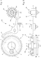
figure 1 représente, de façon schématisée, et en plan, un mécanisme d'embrayage simple selon l'invention; - la
figure 2 représente, de façon schématisée, et en coupe par les principaux points de contact, le mécanisme de lafigure 1 ; - la
figure 3 représente, de façon schématisée, et en plan, un mécanisme d'embrayage double selon l'invention; - la
figure 4 représente, de façon schématisée, et en coupe par les principaux points de contact, le mécanisme de lafigure 3 , laquelle représente en partie supérieure la vue selon AA de lafigure 4 , et en partie inférieure la vue selon BB de lafigure 4 ; - la
figure 5 est un schéma-blocs représentant une pièce d'horlogerie, notamment une montre, comportant un mouvement 500 comportant un tel mécanisme de transmission, et comportant encore un autre tel mécanisme de transmission; - la
figure 6 représente, de façon schématisée, et en coupe par les principaux points de contact, un mécanisme d'embrayage simple à différentiel sphérique et blocage par châssis; - la
figure 7 représente, de façon schématisée, et en coupe par les principaux points de contact, un mécanisme d'embrayage simple à différentiel à deux entrées solaires et blocage par châssis. - L'invention concerne un mécanisme de transmission 100 d'horlogerie, agencé pour être intégré dans un mouvement d'horlogerie 500, et comportant au moins un mécanisme différentiel 10.
- Ce mécanisme différentiel 10 comporte au moins un mobile satellite 3, qui est monté fou en pivotement, et au moins trois mobiles principaux constituant des entrées ou sorties du mécanisme différentiel 10. Ces trois mobiles principaux sont constitués par un châssis 60, un premier mobile 1 agencé pour coopérer avec un premier rouage, et un deuxième mobile 2 agencé pour coopérer avec un deuxième rouage. L'un seul de ces trois mobiles principaux est porteur d'au moins un tel mobile satellite 3 engrenant en permanence avec les deux autres mobiles principaux, soit directement, soit au travers d'au moins un mobile intermédiaire 8 qui engrène en permanence avec l'un des deux autres mobiles principaux, ou qui est solidaire en rotation de l'un des deux autres mobiles principaux.
- Ce mécanisme différentiel 10 est apte à relier cinématiquement le premier mobile 1 et le deuxième mobile 2 dans une position d'embrayage, et à les désolidariser cinématiquement dans une position de débrayage.
- Selon l'invention, le mécanisme de transmission 100 comporte encore des moyens de commande 20, qui sont agencés pour bloquer un seul de ces trois mobiles principaux, pour réaliser l'embrayage du mécanisme différentiel 10, ou pour libérer entièrement le châssis 60 et le premier mobile 1 et le deuxième mobile 2 pour réaliser le débrayage du mécanisme différentiel 10, selon la position imprimée aux moyens de commande 20 par un sélecteur 30 que comporte le mécanisme de transmission 100 et qui est agencé pour coopérer avec un actionneur que comporte un mouvement d'horlogerie 500, ou/et pour être manoeuvré par un utilisateur, ou bien encore pour à la fois coopérer avec un tel actionneur et être manoeuvrable par un utilisateur.
- Plus particulièrement, ces moyens de commande 20 sont rappelés vers un mobile de blocage. Ce mobile de blocage est celui des trois mobiles principaux sur lequel se fait le blocage du mécanisme différentiel 10 en position d'embrayage, par des moyens de rappel élastique 40, qui sont agencés pour exercer sur ce mobile de blocage un couple d'engrènement ou de friction, dont le tarage autorise un débrayage de sécurité quand le couple transmis de l'un à l'autre des autres mobiles principaux, qui ne constituent pas ce mobile de blocage, est supérieur au couple d'engrènement ou de friction.
- Dans une réalisation non limitative illustrée par les figures, ce sélecteur 30 comporte au moins une roue à colonnes 31, qui est agencée pour, selon sa position angulaire, modifier la position angulaire d'une bascule 21 que comportent les moyens de commande 20. Cette bascule 21 comporte un premier bec 22 qui est agencé pour immobiliser ou libérer, selon sa position, une denture périphérique que comporte le mobile de blocage.
- Avantageusement, le mobile de blocage comporte une denture extérieure à dents de loup, de façon à permettre un débrayage de sécurité dans un sens de rotation.
- De façon particulière, le mécanisme de transmission 100 comporte encore des moyens de verrouillage mécanique 50, qui sont agencés pour être manoeuvrés par un actionneur que comporte un mouvement d'horlogerie 500 ou/et par un utilisateur, et qui sont agencés pour bloquer ces moyens de commande 20 dans une position embrayée ou débrayée.
- Dans une réalisation particulière non limitative, le châssis 60, le premier mobile 1, et le deuxième mobile 2 sont agencés pour pivoter autour d'axes parallèles à une même direction de différentiel.
- Dans une variante, chaque mobile satellite 3 est agencé pour pivoter autour d'un axe parallèle à cette direction de différentiel.
- Dans une autre variante, chaque mobile satellite 3 est agencé pour pivoter autour d'un axe perpendiculaire à la direction de différentiel.
- Dans une autre variante encore, chaque mobile satellite 3 est agencé pour pivoter autour d'un axe oblique et non perpendiculaire par rapport à la direction de différentiel.
- Dans une réalisation particulière, non limitative, ce mobile satellite 3 est un pignon satellite. Dans le cas particulier de la
figure 7 , le mobile satellite est composé d'un pignon et d'une roue. - Dans un cas particulier, notamment sur les réalisations illustrées par les
figures 6 et 7 , le mobile de blocage, qui est celui desdits trois mobiles principaux sur lequel se fait le blocage du mécanisme différentiel 10 en position d'embrayage est le châssis 60. - Dans un mode particulier de réalisation, et tel que visible sur les figures, ce châssis 60 est une couronne 6.
- Plus particulièrement, le au moins un mobile satellite 3, ou encore chaque mobile satellite 3, est porté par le premier mobile 1 ou le deuxième mobile 2 et engrène en permanence avec une denture 4 d'un arbre 5 solidaire au moins en rotation du deuxième mobile 2 ou respectivement du premier mobile 1, et le au moins un satellite 3, ou encore chaque mobile satellite 3,engrène en permanence avec ladite couronne 6.
- Plus particulièrement encore, tel que visible sur les
figures 1 et 2 , ce mécanisme différentiel 10 comporte au moins un train épicycloïdal, dont le premier mobile 1 constitue le porte-satellites, le deuxième mobile 2 constitue le planétaire intérieur, et dont la couronne 6 constitue le planétaire extérieur et est coaxiale au deuxième mobile 2 et au premier mobile 1. Chaque satellite 3 de ce train épicycloïdal est enfermé entre le premier mobile 1 et le deuxième mobile 2, ou entre le premier mobile 1 et un bâti 7 que comporte le mécanisme de transmission 100, ce bâti n'est pas représenté afin d ene pas surcharger la figure. Dans un cas particulier, ce bâti 7 est solidaire du deuxième mobile 2. - L'utilisation d'un système de différentiel simple n'est pas limitative. En effet, on peut utiliser de façon similaire un différentiel à satellite et deux couronnes, un différentiel à deux pignons solaires, un différentiel sphérique, ou autre. L'utilisation d'une couronne pour le blocage n'est pas limitative, il peut en effet être avantageux, selon les rapports de transmission à établir, de réaliser le blocage sur l'une ou l'autre entrée ou sortie d'un de ces rouages différentiels.
- Le principe de l'invention est généralisable à un mécanisme différentiel 10 qui comporte plusieurs étages, et notamment chaque étage comportant un train épicycloïdal.
- Plus particulièrement un mécanisme d'embrayage double est d'un emploi courant en horlogerie.
- En couplant deux mécanismes d'embrayage simple selon la
figure 1 , on peut obtenir la fonction : embrayage sur sortie 1, position neutre et embrayage sur sortie 2. La position neutre n'est d'ailleurs pas obligatoire. Les deux embrayages peuvent être commandés séparément. - Les
figures 3 et 4 illustrent un tel embrayage double, avec un train épicycloïdal supplémentaire dont un troisième mobile 91 constitue le porte-satellites, le deuxième mobile 2 constitue le planétaire intérieur, et dont une couronne 96 constitue le planétaire extérieur et est coaxiale au deuxième mobile 2 et à un troisième mobile 91, et dont chaque satellite secondaire 93 est enfermé entre le troisième mobile 91 et le bâti 7. Et les moyens de commande 20 comportent une bascule 21 qui comporte un premier bec 22 agencé pour immobiliser ou libérer, selon sa position, une denture périphérique que comporte le mobile de blocage, et qui comporte un deuxième bras 29 comportant un deuxième bec 28 à son extrémité distale. - Dans un mode particulier de réalisation et tel qu'illustré par les figures, au moins un train épicycloïdal, et plus particulièrement chaque train épicycloïdal, comporte uniquement des mécanismes d'entraînement par engrenage.
- Dans un autre mode particulier de réalisation, au moins un train épicycloïdal, et plus particulièrement chaque train épicycloïdal, comporte au moins un mécanisme d'entraînement par friction.
- La
figure 6 illustre un mécanisme de transmission 100 qui comporte un embrayage simple à mécanisme différentiel 10 sphérique, et avec blocage par châssis, qui comporte un tel châssis 60 enfermé entre un premier mobile 1 et un deuxième mobile 2, et qui porte un moyeu 61 de guidage en rotation folle de chaque mobile satellite 3 d'axe perpendiculaire à une direction de différentiel, à laquelle sont parallèles les axes de pivotement des trois mobiles principaux. Chaque mobile satellite 3 engrène en permanence avec le premier mobile 1 et avec le deuxième mobile 2. - La
figure 7 illustre un mécanisme de transmission 100 comporte un embrayage simple à mécanisme différentiel 10 à deux entrées solaires, et avec blocage par châssis, qui comporte un tel châssis 60 enfermé entre un premier mobile 1 et un deuxième mobile 2, et qui porte un moyeu 61 de guidage en rotation folle de chaque mobile satellite 3 d'axe parallèle à une direction de différentiel à laquelle sont parallèles les axes de pivotement des trois mobiles principaux. Chaque mobile satellite 3 engrèneen permanence avec un mobile intermédiaire 8 qui engrène en permanence avec l'un des deux autres mobiles principaux, ou qui est solidaire en rotation de l'un des deux autres mobiles principaux. - Plus particulièrement le mécanisme différentiel 10 comporte au moins deux entrées ou sorties constituées par un premier mobile 1 agencé pour coopérer avec un premier rouage et un deuxième mobile 2 agencé pour coopérer avec un deuxième rouage, le mécanisme différentiel 10 étant apte à relier cinématiquement le premier mobile 1 et le deuxième mobile 2 dans une position d'embrayage, et à les désolidariser cinématiquement dans une position de débrayage.
- L'invention comporte ainsi un rouage différentiel dont deux entrées servent à la transmission de la rotation du rouage alors que la troisième entrée sert à embrayer et débrayer la transmission.
- Plus particulièrement, et tel que visible sur les
figures 1 à 4 , le mécanisme différentiel 10 comporte au moins un mobile satellite 3, qui est porté par le premier mobile 1, et qui engrène en permanence avec une denture 4 d'un arbre 5 solidaire au moins en rotation du deuxième mobile 2. Cet au moins un satellite 3 engrène en permanence avec une couronne 6 constituant une autre entrée ou sortie du mécanisme différentiel 10. Les moyens de commande 20 sont ici agencés pour bloquer la couronne 6, pour réaliser l'embrayage du mécanisme différentiel 10, ou pour libérer entièrement la couronne 6, pour réaliser le débrayage du mécanisme différentiel 10, selon la position imprimée aux moyens de commande 20 par un tel sélecteur 30. - Lorsque le sélecteur 30 et les moyens de commande 20, qui comportent, non limitativement sur la réalisation particulière illustrée par les figures, une bascule 21 comportant un premier bec 22 à une extrémité, verrouillent par ce premier bec 22 la denture de la couronne 6 extérieure du rouage différentiel, la rotation appliquée à l'entrée 2 est transmise à la sortie 1.
- Lorsque le sélecteur 30 et les moyens de commande 20 déverrouillent la denture de la couronne 6 extérieure du rouage différentiel, la rotation appliquée à l'entrée 2 est transmise à la couronne 6 du différentiel qui n'est plus verrouillée, peut alors tourner librement, et supprimer la transmission de couple vers la sortie 1.
- Dans cet exemple non limitatif, la commande est pilotée par un sélecteur 30 qui comporte au moins une roue à colonnes 31 agencée pour, selon sa position angulaire, modifier la position angulaire de la bascule 21 que comportent les moyens de commande 20. D'autres moyens de commande alternatifs sont utilisables, tels que navette, bascule, ou autre.
- Dans la réalisation illustrée par les
figures 1 et3 , le verrouillage est indirect par des moyens de rappel élastique 40 sous la forme d'un ressort de commande ici relié à un bâti 7, ou à une platine, un pont ou similaire, ce qui offre la possibilité d'un débrayage de sécurité si le couple transmis devient supérieur au couple de passage des dents de la couronne 6 sur la commande. Ainsi les moyens de commande 20 sont rappelés vers la couronne 6, pour réaliser l'embrayage du mécanisme différentiel 10, par des moyens de rappel élastique 40 agencés pour exercer sur la couronne 6 un couple d'engrènement ou de friction, dont le tarage autorise un débrayage de sécurité quand le couple transmis du premier mobile 1 au deuxième mobile 2, ou réciproquement, est supérieur au couple d'engrènement ou de friction. - Dans une variante avantageuse, et tel que visible sur la
figure 3 , la couronne 6 comporte une denture extérieure à dents de loup de façon à permettre un débrayage de sécurité dans un sens de rotation. - L'invention concerne encore un mouvement d'horlogerie 500 comportant au moins un tel mécanisme de transmission 100.
- L'invention concerne encore une pièce d'horlogerie 1000, en particulier une montre, comportant au moins un tel mouvement 500 et/ou comportant au moins un tel mécanisme de transmission 100.
- En somme, l'invention constitue une solution alternative aux solutions connues, et présente l'avantage de limiter le nombre de composants en mouvement pour réaliser la fonction d'embrayage et débrayage, en particulier en comparaison avec les pinces des embrayages verticaux.
- L'invention permet de limiter les efforts (forces et/ou couples) nécessaires pour assurer l'embrayage et le débrayage.
- L'invention peut être dimensionnée pour assurer la transmission d'un couple plus important, notamment dans le cas de la construction d'un embrayage vertical de chronographe où le couple est assuré par une friction.
- L'invention permet la construction d'embrayages simples comme l'embrayage de chronographe: On/Off, et doubles comme les mécanismes de remontage et mise à l'heure: fonction 1 / fonction 2.
- L'invention permet, encore, de dimensionner un seuil de couple avec débrayage de sécurité.
Claims (22)
- Mécanisme de transmission (100) d'horlogerie, agencé pour être intégré dans un mouvement d'horlogerie (500) et comportant au moins un mécanisme différentiel (10) comportant au moins un mobile satellite (3) monté fou en pivotement et au moins trois mobiles principaux constituant des entrées ou sorties dudit mécanisme différentiel (10), lesquels trois mobiles principaux sont constitués par un châssis (60), un premier mobile (1) agencé pour coopérer avec un premier rouage, et un deuxième mobile (2) agencé pour coopérer avec un deuxième rouage, l'un seul desdits trois mobiles principaux étant porteur d'au moins un dit mobile satellite (3) engrenant en permanence avec les deux autres mobiles principaux, soit directement, soit au travers d'au moins un mobile intermédiaire (8) qui engrène en permanence avec l'un desdits deux autres mobiles principaux ou qui est solidaire en rotation de l'un desdits deux autres mobiles principaux, ledit mécanisme différentiel (10) étant apte à relier cinématiquement ledit premier mobile (1) et ledit deuxième mobile (2) dans une position d'embrayage, et à les désolidariser cinématiquement dans une position de débrayage, caractérisé en ce que ledit mécanisme de transmission (100) comporte encore des moyens de commande (20) agencés pour bloquer un seul desdits trois mobiles principaux, pour réaliser l'embrayage dudit mécanisme différentiel (10), ou pour libérer entièrement ledit châssis (60) et ledit premier mobile (1) et ledit deuxième mobile (2) pour réaliser le débrayage dudit mécanisme différentiel (10), selon la position imprimée auxdits moyens de commande (20) par un sélecteur (30) que comporte ledit mécanisme de transmission (100) et qui est agencé pour coopérer avec un actionneur que comporte un dit mouvement d'horlogerie (500), ou/et pour être manoeuvré par un utilisateur.
- Mécanisme de transmission (100) selon la revendication 1, caractérisé en ce que lesdits moyens de commande (20) sont rappelés vers un mobile de blocage qui est celui desdits trois mobiles principaux sur lequel se fait le blocage dudit mécanisme différentiel (10) en position d'embrayage, par des moyens de rappel élastique (40) agencés pour exercer sur ledit mobile de blocage un couple d'engrènement ou de friction, dont le tarage autorise un débrayage de sécurité quand le couple transmis de l'un à l'autre des autres mobiles principaux distincts dudit mobile de blocage est supérieur audit couple d'engrènement ou de friction.
- Mécanisme de transmission (100) selon la revendication 1 ou 2, caractérisé en ce que ledit sélecteur (30) comporte au moins une roue à colonnes (31) agencée pour, selon sa position angulaire, modifier la position angulaire d'une bascule (21) que comportent lesdits moyens de commande (20), laquelle bascule (21) comporte un premier bec (22) agencé pour immobiliser ou libérer, selon sa position, une denture périphérique que comporte ledit mobile de blocage.
- Mécanisme de transmission (100) selon la revendication 2 ou 3, caractérisé en ce que ledit mobile de blocage comporte une denture extérieure à dents de loup de façon à permettre un débrayage de sécurité dans un sens de rotation.
- Mécanisme de transmission (100) selon l'une des revendications 1 à 4, caractérisé en ce que ledit mécanisme de transmission (100) comporte encore des moyens de verrouillage mécanique (50), agencés pour être manoeuvrés par un actionneur que comporte un dit mouvement d'horlogerie (500) ou/et par un utilisateur, et qui sont agencés pour bloquer lesdits moyens de commande (20) dans une position embrayée ou débrayée.
- Mécanisme de transmission (100) selon l'une des revendications 1 à 5, caractérisé en ce que ledit châssis (60), ledit premier mobile (1) et ledit deuxième mobile (2) sont agencés pour pivoter autour d'axes parallèles à une même direction de différentiel.
- Mécanisme de transmission (100) selon la revendication 6, caractérisé en ce que chaque dit mobile satellite (3) est agencé pour pivoter autour d'un axe parallèle à ladite direction de différentiel.
- Mécanisme de transmission (100) selon la revendication 6, caractérisé en ce que chaque dit mobile satellite (3) est agencé pour pivoter autour d'un axe perpendiculaire à ladite direction de différentiel.
- Mécanisme de transmission (100) selon la revendication 6, caractérisé en ce que chaque dit mobile satellite (3) est agencé pour pivoter autour d'un axe oblique et non perpendiculaire par rapport à ladite direction de différentiel.
- Mécanisme de transmission (100) selon l'une des revendications 1 à 9, caractérisé en ce que le mobile de blocage qui est celui desdits trois mobiles principaux sur lequel se fait le blocage dudit mécanisme différentiel (10) en position d'embrayage est ledit châssis (60).
- Mécanisme de transmission (100) selon l'une des revendications 1 à 10, caractérisé en ce que ledit châssis (60) est une couronne (6).
- Mécanisme de transmission (100) selon la revendication 11, caractérisé en ce que ledit au moins un mobile satellite (3) est porté par ledit premier mobile (1) ou ledit deuxième mobile (2) et engrène en permanence avec une denture (4) d'un arbre (5) solidaire au moins en rotation dudit deuxième mobile (2) ou respectivement dudit premier mobile (1), et ledit au moins un satellite (3) engrenant en permanence avec ladite couronne (6).
- Mécanisme de transmission (100) selon la revendication 12, caractérisé en ce que ledit mécanisme différentiel (10) comporte au moins un train épicycloïdal dont ledit premier mobile (1) constitue le porte-satellites, ledit deuxième mobile (2) constitue le planétaire intérieur, et dont ladite couronne (6) constitue le planétaire extérieur et est coaxiale audit deuxième mobile (2) et audit premier mobile (1), et dont chaque dit satellite (3) est enfermé entre ledit premier mobile (1) et ledit deuxième mobile (2) ou entre ledit premier mobile (1) et un bâti (7) que comporte ledit mécanisme de transmission (100).
- Mécanisme de transmission (100) selon la revendication 13, caractérisé en ce que ledit bâti (7) est solidaire dudit deuxième mobile (2).
- Mécanisme de transmission (100) selon la revendication 13 ou 14, caractérisé en ce que ledit mécanisme différentiel (10) comporte un embrayage double, avec un train épicycloïdal supplémentaire dont un troisième mobile (91) constitue le porte-satellites, ledit deuxième mobile (2) constitue le planétaire intérieur, et dont une couronne (96) constitue le planétaire extérieur et est coaxiale audit premier mobile (2) et à un troisième mobile (91), et dont chaque satellite secondaire (93) est enfermé entre ledit troisième mobile (91) et ledit bâti (7), et en ce que lesdits moyens de commande (20) comportent une bascule (21) qui comporte un premier bec (22) agencé pour immobiliser ou libérer, selon sa position, une denture périphérique que comporte ledit mobile de blocage, et qui comporte un deuxième bras (29) comportant un deuxième bec (28) à son extrémité distale.
- Mécanisme de transmission (100) selon l'une des revendications 13 à 15, caractérisé en ce que chaque dit train épicycloïdal comporte uniquement des mécanismes d'entraînement par engrenage.
- Mécanisme de transmission (100) selon l'une des revendications 13 à 15, caractérisé en ce qu'au moins un dit train épicycloïdal comporte au moins un mécanisme d'entraînement par friction.
- Mécanisme de transmission (100) selon l'une des revendications 1 à 17, caractérisé en ce que ledit mécanisme différentiel (10) comporte plusieurs étages comportant chacun un train épicycloïdal.
- Mécanisme de transmission (100) selon l'une des revendications 1 à 11, caractérisé en ce que ledit mécanisme de transmission (100) comporte un embrayage simple à mécanisme différentiel (10) sphérique, et avec blocage par châssis, qui comporte un dit châssis (60) enfermé entre un dit premier mobile (1) et un dit deuxième mobile (2), et qui porte un moyeu (61) de guidage en rotation folle de chaque dit mobile satellite (3) d'axe perpendiculaire à une direction de différentiel à laquelle sont parallèles les axes de pivotement desdits trois mobiles principaux, chaque dit mobile satellite (3) engrenant en permanence avec ledit premier mobile (1) et avec ledit deuxième mobile (2).
- Mécanisme de transmission (100) selon l'une des revendications 1 à 11, caractérisé en ce que ledit mécanisme de transmission (100) comporte un embrayage simple à mécanisme différentiel (10) à deux entrées solaires, et avec blocage par châssis, qui comporte un dit châssis (60) enfermé entre un dit premier mobile (1) et un dit deuxième mobile (2), et qui porte un moyeu (61) de guidage en rotation folle de chaque dit mobile satellite (3) d'axe parallèle à une direction de différentiel à laquelle sont parallèles les axes de pivotement desdits trois mobiles principaux, chaque dit mobile satellite (3) engrenant en permanence avec un dit mobile intermédiaire (8) qui engrène en permanence avec l'un desdits deux autres mobiles principaux ou qui est solidaire en rotation de l'un desdits deux autres mobiles principaux.
- Mouvement d'horlogerie (500) comportant au moins un mécanisme de transmission (100) selon l'une des revendications 1 à 20.
- Pièce d'horlogerie (1000) comportant au moins un mouvement (500) selon la revendication 21 et/ou comportant au moins un mécanisme de transmission (100) selon l'une des revendications 1 à 20.
Priority Applications (4)
| Application Number | Priority Date | Filing Date | Title |
|---|---|---|---|
| EP18163966.7A EP3547045B1 (fr) | 2018-03-26 | 2018-03-26 | Mécanisme de transmission d'horlogerie à effort d'embrayage réduit |
| JP2019045588A JP6806828B2 (ja) | 2018-03-26 | 2019-03-13 | 連結力を低減した計時器伝動機構 |
| US16/360,498 US11415942B2 (en) | 2018-03-26 | 2019-03-21 | Timepiece transmission mechanism with reduced coupling force |
| CN201910227997.7A CN110361954B (zh) | 2018-03-26 | 2019-03-25 | 具有降低的联接力的钟表传动机构 |
Applications Claiming Priority (1)
| Application Number | Priority Date | Filing Date | Title |
|---|---|---|---|
| EP18163966.7A EP3547045B1 (fr) | 2018-03-26 | 2018-03-26 | Mécanisme de transmission d'horlogerie à effort d'embrayage réduit |
Publications (2)
| Publication Number | Publication Date |
|---|---|
| EP3547045A1 true EP3547045A1 (fr) | 2019-10-02 |
| EP3547045B1 EP3547045B1 (fr) | 2022-05-04 |
Family
ID=61800387
Family Applications (1)
| Application Number | Title | Priority Date | Filing Date |
|---|---|---|---|
| EP18163966.7A Active EP3547045B1 (fr) | 2018-03-26 | 2018-03-26 | Mécanisme de transmission d'horlogerie à effort d'embrayage réduit |
Country Status (4)
| Country | Link |
|---|---|
| US (1) | US11415942B2 (fr) |
| EP (1) | EP3547045B1 (fr) |
| JP (1) | JP6806828B2 (fr) |
| CN (1) | CN110361954B (fr) |
Families Citing this family (1)
| Publication number | Priority date | Publication date | Assignee | Title |
|---|---|---|---|---|
| EP4180880A1 (fr) | 2021-11-10 | 2023-05-17 | Montres Breguet S.A. | Dispositif d'affichage d'une succession d'indications d'une grandeur temporelle pour une pièce d'horlogerie |
Citations (2)
| Publication number | Priority date | Publication date | Assignee | Title |
|---|---|---|---|---|
| CH216001A (fr) * | 1939-08-22 | 1941-07-31 | Sonceboz Sa | Pièce d'horlogerie à chronographe. |
| EP3021175A1 (fr) * | 2014-11-13 | 2016-05-18 | Société anonyme de la Manufacture d'Horlogerie Audemars Piguet & Cie | Dispositif de rattrapante à train épicycloïdale pour pièce d'horlogerie |
Family Cites Families (11)
| Publication number | Priority date | Publication date | Assignee | Title |
|---|---|---|---|---|
| ATE316663T1 (de) * | 2002-10-07 | 2006-02-15 | Vaucher Mft Fleurier Sa | Chronographenuhrwerk |
| EP1708051A1 (fr) * | 2005-03-31 | 2006-10-04 | Zenith International SA | Pièce d'horlogerie comportant un réveil |
| EP1944662A1 (fr) * | 2007-01-15 | 2008-07-16 | Vaucher Manufacture Fleurier SA | Mécanisme de sonnerie des heures |
| EP2015145B1 (fr) * | 2007-06-11 | 2013-05-01 | Chopard Manufacture SA | Dispositif d'embrayage vertical pour pièce d'horlogerie |
| CH702924B1 (fr) * | 2010-06-03 | 2011-10-14 | Patek Philippe Sa Geneve | Mobile à embrayage unidirectionnel, mécanisme de remontage et pièce d'horlogerie comportant ledit mobile. |
| CH703247B1 (fr) * | 2010-06-04 | 2014-12-15 | Milus Internat Sa | Indicateur acoustique de la réserve de marche d'une pièce d'horlogerie. |
| EP2410388B1 (fr) * | 2010-07-21 | 2018-04-18 | Blancpain S.A. | Pièce d'horlogerie à double affichage |
| CN103842916B (zh) * | 2011-09-01 | 2017-06-16 | 劳力士有限公司 | 能够显示两个时区的计时器 |
| EP2615506B1 (fr) * | 2012-01-10 | 2014-06-25 | Montres Breguet SA | Dispositif de correction rapide d'un système d'affichage |
| JP6262364B2 (ja) * | 2014-03-26 | 2018-01-17 | ザ・スウォッチ・グループ・マネージメント・サービシイズ・エイ ジー | 計時器用制御システム |
| EP3018535B1 (fr) * | 2014-11-07 | 2018-09-05 | Montres Breguet SA | Dispositif de remontage à agencement d'entraînement unidirectionnel |
-
2018
- 2018-03-26 EP EP18163966.7A patent/EP3547045B1/fr active Active
-
2019
- 2019-03-13 JP JP2019045588A patent/JP6806828B2/ja active Active
- 2019-03-21 US US16/360,498 patent/US11415942B2/en active Active
- 2019-03-25 CN CN201910227997.7A patent/CN110361954B/zh active Active
Patent Citations (2)
| Publication number | Priority date | Publication date | Assignee | Title |
|---|---|---|---|---|
| CH216001A (fr) * | 1939-08-22 | 1941-07-31 | Sonceboz Sa | Pièce d'horlogerie à chronographe. |
| EP3021175A1 (fr) * | 2014-11-13 | 2016-05-18 | Société anonyme de la Manufacture d'Horlogerie Audemars Piguet & Cie | Dispositif de rattrapante à train épicycloïdale pour pièce d'horlogerie |
Also Published As
| Publication number | Publication date |
|---|---|
| US20190294110A1 (en) | 2019-09-26 |
| JP2019174457A (ja) | 2019-10-10 |
| CN110361954B (zh) | 2021-05-04 |
| CN110361954A (zh) | 2019-10-22 |
| EP3547045B1 (fr) | 2022-05-04 |
| US11415942B2 (en) | 2022-08-16 |
| JP6806828B2 (ja) | 2021-01-06 |
Similar Documents
| Publication | Publication Date | Title |
|---|---|---|
| EP1970778B1 (fr) | Pièce d'horlogerie comprenant un dispositif indicateur de réserve de marche | |
| EP2945026B1 (fr) | Mécanisme de correction rapide d'horlogerie | |
| EP3499319A2 (fr) | Bascule d'embrayage et dispositif d'embrayage pour mecanisme horloger | |
| EP3278183A1 (fr) | Mécanisme de remontage et/ou de correction d'au moins une fonction horlogère et dispositif de sélection d'une fonction horlogère | |
| EP3584642A1 (fr) | Mecanisme de reglage pour mecanisme d'affichage d'horlogerie a rouleau | |
| EP1978419B1 (fr) | Dispositif de remontage comprenant un accouplement à sens unique | |
| CH714836A2 (fr) | Mécanisme de transmission d'horlogerie avec fonction d'embrayage et de débrayage. | |
| EP3547045B1 (fr) | Mécanisme de transmission d'horlogerie à effort d'embrayage réduit | |
| EP3316048B1 (fr) | Mécanisme horloger d'affichage et de correction d'une pluralité d'informations | |
| EP2226687B1 (fr) | Dispositif de débrayage pour mécanisme horloger, et mouvement de montre comportant ce dispositif | |
| EP1862871B1 (fr) | Pièce d'horlogerie comportant un dispositif de mise à l'heure amélioré | |
| EP3396469A1 (fr) | Mécanisme de commande déportée d'horlogerie | |
| EP3376308B1 (fr) | Mécanisme de remontage d'une pièce d'horlogerie | |
| EP4375759A1 (fr) | Dispositif d'accouplement pour pièce d'horlogerie | |
| EP3944026B1 (fr) | Mécanisme horloger a chaîne de comptage | |
| EP2765079B1 (fr) | Siège de cabine pour aéronef | |
| CH719259A2 (fr) | Système de remontage automatique pour mouvement d'horlogerie. | |
| EP3376309B1 (fr) | Mécanisme de remontage d'une pièce d'horlogerie | |
| EP4296788B1 (fr) | Dispositif de remontage automatique d'un ressort de barillet d'un mouvement horloger | |
| EP4216000B1 (fr) | Dispositif de commande pour une pièce d'horlogerie | |
| EP4414792A1 (fr) | Mécanisme de correction d'au moins un premier et un deuxième dispositif indicateur d'une pièce d'horlogerie | |
| EP3232275B1 (fr) | Mecanisme de remontage pour une piece d'horlogerie comportant au moins deux barillets, et piece d'horlogerie comprenant un tel mecanisme | |
| EP3361323A1 (fr) | Système de remontage de pièce d'horlogerie | |
| CH713726A2 (fr) | Mécanisme de commande déportée d'horlogerie. | |
| CH701670B1 (fr) | Mécanisme de remontage d'une montre par une partie de corne mobile. |
Legal Events
| Date | Code | Title | Description |
|---|---|---|---|
| PUAI | Public reference made under article 153(3) epc to a published international application that has entered the european phase |
Free format text: ORIGINAL CODE: 0009012 |
|
| STAA | Information on the status of an ep patent application or granted ep patent |
Free format text: STATUS: THE APPLICATION HAS BEEN PUBLISHED |
|
| AK | Designated contracting states |
Kind code of ref document: A1 Designated state(s): AL AT BE BG CH CY CZ DE DK EE ES FI FR GB GR HR HU IE IS IT LI LT LU LV MC MK MT NL NO PL PT RO RS SE SI SK SM TR |
|
| AX | Request for extension of the european patent |
Extension state: BA ME |
|
| STAA | Information on the status of an ep patent application or granted ep patent |
Free format text: STATUS: REQUEST FOR EXAMINATION WAS MADE |
|
| 17P | Request for examination filed |
Effective date: 20200402 |
|
| RBV | Designated contracting states (corrected) |
Designated state(s): AL AT BE BG CH CY CZ DE DK EE ES FI FR GB GR HR HU IE IS IT LI LT LU LV MC MK MT NL NO PL PT RO RS SE SI SK SM TR |
|
| GRAP | Despatch of communication of intention to grant a patent |
Free format text: ORIGINAL CODE: EPIDOSNIGR1 |
|
| STAA | Information on the status of an ep patent application or granted ep patent |
Free format text: STATUS: GRANT OF PATENT IS INTENDED |
|
| INTG | Intention to grant announced |
Effective date: 20211119 |
|
| GRAS | Grant fee paid |
Free format text: ORIGINAL CODE: EPIDOSNIGR3 |
|
| GRAA | (expected) grant |
Free format text: ORIGINAL CODE: 0009210 |
|
| STAA | Information on the status of an ep patent application or granted ep patent |
Free format text: STATUS: THE PATENT HAS BEEN GRANTED |
|
| AK | Designated contracting states |
Kind code of ref document: B1 Designated state(s): AL AT BE BG CH CY CZ DE DK EE ES FI FR GB GR HR HU IE IS IT LI LT LU LV MC MK MT NL NO PL PT RO RS SE SI SK SM TR |
|
| REG | Reference to a national code |
Ref country code: GB Ref legal event code: FG4D Free format text: NOT ENGLISH |
|
| REG | Reference to a national code |
Ref country code: CH Ref legal event code: EP |
|
| REG | Reference to a national code |
Ref country code: AT Ref legal event code: REF Ref document number: 1489726 Country of ref document: AT Kind code of ref document: T Effective date: 20220515 |
|
| REG | Reference to a national code |
Ref country code: IE Ref legal event code: FG4D Free format text: LANGUAGE OF EP DOCUMENT: FRENCH Ref country code: DE Ref legal event code: R096 Ref document number: 602018034779 Country of ref document: DE |
|
| REG | Reference to a national code |
Ref country code: LT Ref legal event code: MG9D |
|
| REG | Reference to a national code |
Ref country code: NL Ref legal event code: MP Effective date: 20220504 |
|
| REG | Reference to a national code |
Ref country code: AT Ref legal event code: MK05 Ref document number: 1489726 Country of ref document: AT Kind code of ref document: T Effective date: 20220504 |
|
| PG25 | Lapsed in a contracting state [announced via postgrant information from national office to epo] |
Ref country code: SE Free format text: LAPSE BECAUSE OF FAILURE TO SUBMIT A TRANSLATION OF THE DESCRIPTION OR TO PAY THE FEE WITHIN THE PRESCRIBED TIME-LIMIT Effective date: 20220504 Ref country code: PT Free format text: LAPSE BECAUSE OF FAILURE TO SUBMIT A TRANSLATION OF THE DESCRIPTION OR TO PAY THE FEE WITHIN THE PRESCRIBED TIME-LIMIT Effective date: 20220905 Ref country code: NO Free format text: LAPSE BECAUSE OF FAILURE TO SUBMIT A TRANSLATION OF THE DESCRIPTION OR TO PAY THE FEE WITHIN THE PRESCRIBED TIME-LIMIT Effective date: 20220804 Ref country code: NL Free format text: LAPSE BECAUSE OF FAILURE TO SUBMIT A TRANSLATION OF THE DESCRIPTION OR TO PAY THE FEE WITHIN THE PRESCRIBED TIME-LIMIT Effective date: 20220504 Ref country code: LT Free format text: LAPSE BECAUSE OF FAILURE TO SUBMIT A TRANSLATION OF THE DESCRIPTION OR TO PAY THE FEE WITHIN THE PRESCRIBED TIME-LIMIT Effective date: 20220504 Ref country code: HR Free format text: LAPSE BECAUSE OF FAILURE TO SUBMIT A TRANSLATION OF THE DESCRIPTION OR TO PAY THE FEE WITHIN THE PRESCRIBED TIME-LIMIT Effective date: 20220504 Ref country code: GR Free format text: LAPSE BECAUSE OF FAILURE TO SUBMIT A TRANSLATION OF THE DESCRIPTION OR TO PAY THE FEE WITHIN THE PRESCRIBED TIME-LIMIT Effective date: 20220805 Ref country code: FI Free format text: LAPSE BECAUSE OF FAILURE TO SUBMIT A TRANSLATION OF THE DESCRIPTION OR TO PAY THE FEE WITHIN THE PRESCRIBED TIME-LIMIT Effective date: 20220504 Ref country code: ES Free format text: LAPSE BECAUSE OF FAILURE TO SUBMIT A TRANSLATION OF THE DESCRIPTION OR TO PAY THE FEE WITHIN THE PRESCRIBED TIME-LIMIT Effective date: 20220504 Ref country code: BG Free format text: LAPSE BECAUSE OF FAILURE TO SUBMIT A TRANSLATION OF THE DESCRIPTION OR TO PAY THE FEE WITHIN THE PRESCRIBED TIME-LIMIT Effective date: 20220804 Ref country code: AT Free format text: LAPSE BECAUSE OF FAILURE TO SUBMIT A TRANSLATION OF THE DESCRIPTION OR TO PAY THE FEE WITHIN THE PRESCRIBED TIME-LIMIT Effective date: 20220504 |
|
| PG25 | Lapsed in a contracting state [announced via postgrant information from national office to epo] |
Ref country code: RS Free format text: LAPSE BECAUSE OF FAILURE TO SUBMIT A TRANSLATION OF THE DESCRIPTION OR TO PAY THE FEE WITHIN THE PRESCRIBED TIME-LIMIT Effective date: 20220504 Ref country code: PL Free format text: LAPSE BECAUSE OF FAILURE TO SUBMIT A TRANSLATION OF THE DESCRIPTION OR TO PAY THE FEE WITHIN THE PRESCRIBED TIME-LIMIT Effective date: 20220504 Ref country code: LV Free format text: LAPSE BECAUSE OF FAILURE TO SUBMIT A TRANSLATION OF THE DESCRIPTION OR TO PAY THE FEE WITHIN THE PRESCRIBED TIME-LIMIT Effective date: 20220504 Ref country code: IS Free format text: LAPSE BECAUSE OF FAILURE TO SUBMIT A TRANSLATION OF THE DESCRIPTION OR TO PAY THE FEE WITHIN THE PRESCRIBED TIME-LIMIT Effective date: 20220904 |
|
| PG25 | Lapsed in a contracting state [announced via postgrant information from national office to epo] |
Ref country code: SM Free format text: LAPSE BECAUSE OF FAILURE TO SUBMIT A TRANSLATION OF THE DESCRIPTION OR TO PAY THE FEE WITHIN THE PRESCRIBED TIME-LIMIT Effective date: 20220504 Ref country code: SK Free format text: LAPSE BECAUSE OF FAILURE TO SUBMIT A TRANSLATION OF THE DESCRIPTION OR TO PAY THE FEE WITHIN THE PRESCRIBED TIME-LIMIT Effective date: 20220504 Ref country code: RO Free format text: LAPSE BECAUSE OF FAILURE TO SUBMIT A TRANSLATION OF THE DESCRIPTION OR TO PAY THE FEE WITHIN THE PRESCRIBED TIME-LIMIT Effective date: 20220504 Ref country code: EE Free format text: LAPSE BECAUSE OF FAILURE TO SUBMIT A TRANSLATION OF THE DESCRIPTION OR TO PAY THE FEE WITHIN THE PRESCRIBED TIME-LIMIT Effective date: 20220504 Ref country code: DK Free format text: LAPSE BECAUSE OF FAILURE TO SUBMIT A TRANSLATION OF THE DESCRIPTION OR TO PAY THE FEE WITHIN THE PRESCRIBED TIME-LIMIT Effective date: 20220504 Ref country code: CZ Free format text: LAPSE BECAUSE OF FAILURE TO SUBMIT A TRANSLATION OF THE DESCRIPTION OR TO PAY THE FEE WITHIN THE PRESCRIBED TIME-LIMIT Effective date: 20220504 |
|
| REG | Reference to a national code |
Ref country code: DE Ref legal event code: R097 Ref document number: 602018034779 Country of ref document: DE |
|
| PLBE | No opposition filed within time limit |
Free format text: ORIGINAL CODE: 0009261 |
|
| STAA | Information on the status of an ep patent application or granted ep patent |
Free format text: STATUS: NO OPPOSITION FILED WITHIN TIME LIMIT |
|
| PG25 | Lapsed in a contracting state [announced via postgrant information from national office to epo] |
Ref country code: AL Free format text: LAPSE BECAUSE OF FAILURE TO SUBMIT A TRANSLATION OF THE DESCRIPTION OR TO PAY THE FEE WITHIN THE PRESCRIBED TIME-LIMIT Effective date: 20220504 |
|
| 26N | No opposition filed |
Effective date: 20230207 |
|
| PG25 | Lapsed in a contracting state [announced via postgrant information from national office to epo] |
Ref country code: SI Free format text: LAPSE BECAUSE OF FAILURE TO SUBMIT A TRANSLATION OF THE DESCRIPTION OR TO PAY THE FEE WITHIN THE PRESCRIBED TIME-LIMIT Effective date: 20220504 |
|
| P01 | Opt-out of the competence of the unified patent court (upc) registered |
Effective date: 20230611 |
|
| PG25 | Lapsed in a contracting state [announced via postgrant information from national office to epo] |
Ref country code: MC Free format text: LAPSE BECAUSE OF FAILURE TO SUBMIT A TRANSLATION OF THE DESCRIPTION OR TO PAY THE FEE WITHIN THE PRESCRIBED TIME-LIMIT Effective date: 20220504 |
|
| REG | Reference to a national code |
Ref country code: BE Ref legal event code: MM Effective date: 20230331 |
|
| PG25 | Lapsed in a contracting state [announced via postgrant information from national office to epo] |
Ref country code: LU Free format text: LAPSE BECAUSE OF NON-PAYMENT OF DUE FEES Effective date: 20230326 |
|
| REG | Reference to a national code |
Ref country code: IE Ref legal event code: MM4A |
|
| PG25 | Lapsed in a contracting state [announced via postgrant information from national office to epo] |
Ref country code: IT Free format text: LAPSE BECAUSE OF FAILURE TO SUBMIT A TRANSLATION OF THE DESCRIPTION OR TO PAY THE FEE WITHIN THE PRESCRIBED TIME-LIMIT Effective date: 20220504 Ref country code: IE Free format text: LAPSE BECAUSE OF NON-PAYMENT OF DUE FEES Effective date: 20230326 |
|
| PG25 | Lapsed in a contracting state [announced via postgrant information from national office to epo] |
Ref country code: BE Free format text: LAPSE BECAUSE OF NON-PAYMENT OF DUE FEES Effective date: 20230331 |
|
| PG25 | Lapsed in a contracting state [announced via postgrant information from national office to epo] |
Ref country code: BG Free format text: LAPSE BECAUSE OF FAILURE TO SUBMIT A TRANSLATION OF THE DESCRIPTION OR TO PAY THE FEE WITHIN THE PRESCRIBED TIME-LIMIT Effective date: 20220504 |
|
| PG25 | Lapsed in a contracting state [announced via postgrant information from national office to epo] |
Ref country code: BG Free format text: LAPSE BECAUSE OF FAILURE TO SUBMIT A TRANSLATION OF THE DESCRIPTION OR TO PAY THE FEE WITHIN THE PRESCRIBED TIME-LIMIT Effective date: 20220504 |
|
| PGFP | Annual fee paid to national office [announced via postgrant information from national office to epo] |
Ref country code: CH Payment date: 20250401 Year of fee payment: 8 |
|
| PG25 | Lapsed in a contracting state [announced via postgrant information from national office to epo] |
Ref country code: CY Free format text: LAPSE BECAUSE OF FAILURE TO SUBMIT A TRANSLATION OF THE DESCRIPTION OR TO PAY THE FEE WITHIN THE PRESCRIBED TIME-LIMIT; INVALID AB INITIO Effective date: 20180326 |
|
| PG25 | Lapsed in a contracting state [announced via postgrant information from national office to epo] |
Ref country code: HU Free format text: LAPSE BECAUSE OF FAILURE TO SUBMIT A TRANSLATION OF THE DESCRIPTION OR TO PAY THE FEE WITHIN THE PRESCRIBED TIME-LIMIT; INVALID AB INITIO Effective date: 20180326 |
|
| PG25 | Lapsed in a contracting state [announced via postgrant information from national office to epo] |
Ref country code: TR Free format text: LAPSE BECAUSE OF FAILURE TO SUBMIT A TRANSLATION OF THE DESCRIPTION OR TO PAY THE FEE WITHIN THE PRESCRIBED TIME-LIMIT Effective date: 20220504 |
|
| REG | Reference to a national code |
Ref country code: CH Ref legal event code: U11 Free format text: ST27 STATUS EVENT CODE: U-0-0-U10-U11 (AS PROVIDED BY THE NATIONAL OFFICE) Effective date: 20260401 |
|
| PGFP | Annual fee paid to national office [announced via postgrant information from national office to epo] |
Ref country code: GB Payment date: 20260219 Year of fee payment: 9 |
|
| PGFP | Annual fee paid to national office [announced via postgrant information from national office to epo] |
Ref country code: DE Payment date: 20260219 Year of fee payment: 9 |
|
| PGFP | Annual fee paid to national office [announced via postgrant information from national office to epo] |
Ref country code: FR Payment date: 20260219 Year of fee payment: 9 |