EP3547013A1 - Verfahren zur bestimmung eines einstärkenbrillenglases - Google Patents
Verfahren zur bestimmung eines einstärkenbrillenglases Download PDFInfo
- Publication number
- EP3547013A1 EP3547013A1 EP18305383.4A EP18305383A EP3547013A1 EP 3547013 A1 EP3547013 A1 EP 3547013A1 EP 18305383 A EP18305383 A EP 18305383A EP 3547013 A1 EP3547013 A1 EP 3547013A1
- Authority
- EP
- European Patent Office
- Prior art keywords
- ophthalmic lens
- single vision
- gazing
- distance
- equal
- Prior art date
- Legal status (The legal status is an assumption and is not a legal conclusion. Google has not performed a legal analysis and makes no representation as to the accuracy of the status listed.)
- Withdrawn
Links
- 230000004438 eyesight Effects 0.000 title claims abstract description 133
- 238000000034 method Methods 0.000 title claims abstract description 28
- 230000003287 optical effect Effects 0.000 claims abstract description 45
- 201000009310 astigmatism Diseases 0.000 claims description 48
- 208000001491 myopia Diseases 0.000 claims description 8
- 230000000007 visual effect Effects 0.000 description 9
- 210000004087 cornea Anatomy 0.000 description 6
- 230000004075 alteration Effects 0.000 description 5
- 210000001747 pupil Anatomy 0.000 description 4
- 208000003464 asthenopia Diseases 0.000 description 2
- 238000004590 computer program Methods 0.000 description 2
- 230000000750 progressive effect Effects 0.000 description 2
- 230000004308 accommodation Effects 0.000 description 1
- 230000002354 daily effect Effects 0.000 description 1
- 230000007547 defect Effects 0.000 description 1
- 230000001419 dependent effect Effects 0.000 description 1
- 230000000694 effects Effects 0.000 description 1
- 230000003203 everyday effect Effects 0.000 description 1
- 210000003128 head Anatomy 0.000 description 1
- 238000012986 modification Methods 0.000 description 1
- 230000004048 modification Effects 0.000 description 1
- 230000000630 rising effect Effects 0.000 description 1
Images


Classifications
-
- G—PHYSICS
- G02—OPTICS
- G02C—SPECTACLES; SUNGLASSES OR GOGGLES INSOFAR AS THEY HAVE THE SAME FEATURES AS SPECTACLES; CONTACT LENSES
- G02C7/00—Optical parts
- G02C7/02—Lenses; Lens systems ; Methods of designing lenses
-
- G—PHYSICS
- G02—OPTICS
- G02C—SPECTACLES; SUNGLASSES OR GOGGLES INSOFAR AS THEY HAVE THE SAME FEATURES AS SPECTACLES; CONTACT LENSES
- G02C7/00—Optical parts
- G02C7/02—Lenses; Lens systems ; Methods of designing lenses
- G02C7/024—Methods of designing ophthalmic lenses
-
- G—PHYSICS
- G02—OPTICS
- G02C—SPECTACLES; SUNGLASSES OR GOGGLES INSOFAR AS THEY HAVE THE SAME FEATURES AS SPECTACLES; CONTACT LENSES
- G02C7/00—Optical parts
- G02C7/02—Lenses; Lens systems ; Methods of designing lenses
- G02C7/022—Ophthalmic lenses having special refractive features achieved by special materials or material structures
-
- G—PHYSICS
- G02—OPTICS
- G02C—SPECTACLES; SUNGLASSES OR GOGGLES INSOFAR AS THEY HAVE THE SAME FEATURES AS SPECTACLES; CONTACT LENSES
- G02C7/00—Optical parts
- G02C7/02—Lenses; Lens systems ; Methods of designing lenses
- G02C7/024—Methods of designing ophthalmic lenses
- G02C7/025—Methods of designing ophthalmic lenses considering parameters of the viewed object
-
- G—PHYSICS
- G02—OPTICS
- G02C—SPECTACLES; SUNGLASSES OR GOGGLES INSOFAR AS THEY HAVE THE SAME FEATURES AS SPECTACLES; CONTACT LENSES
- G02C7/00—Optical parts
- G02C7/02—Lenses; Lens systems ; Methods of designing lenses
- G02C7/024—Methods of designing ophthalmic lenses
- G02C7/027—Methods of designing ophthalmic lenses considering wearer's parameters
-
- G—PHYSICS
- G02—OPTICS
- G02C—SPECTACLES; SUNGLASSES OR GOGGLES INSOFAR AS THEY HAVE THE SAME FEATURES AS SPECTACLES; CONTACT LENSES
- G02C7/00—Optical parts
- G02C7/02—Lenses; Lens systems ; Methods of designing lenses
- G02C7/024—Methods of designing ophthalmic lenses
- G02C7/028—Special mathematical design techniques
-
- G—PHYSICS
- G02—OPTICS
- G02C—SPECTACLES; SUNGLASSES OR GOGGLES INSOFAR AS THEY HAVE THE SAME FEATURES AS SPECTACLES; CONTACT LENSES
- G02C2202/00—Generic optical aspects applicable to one or more of the subgroups of G02C7/00
- G02C2202/20—Diffractive and Fresnel lenses or lens portions
-
- G—PHYSICS
- G02—OPTICS
- G02C—SPECTACLES; SUNGLASSES OR GOGGLES INSOFAR AS THEY HAVE THE SAME FEATURES AS SPECTACLES; CONTACT LENSES
- G02C2202/00—Generic optical aspects applicable to one or more of the subgroups of G02C7/00
- G02C2202/24—Myopia progression prevention
Definitions
- the invention relates to a method implemented by computer means for determining a single vision ophthalmic lens adapted to a wearer, to a computer program product and to a single vision ophthalmic lens adapted to a wearer.
- Single vision ophthalmic lenses are typically calculated to compensate visual defects of a non presbyope ametrope wearer, considering the far vision prescription and looking at objects at far distance, also referred to as infinite distance. But during daily use of single vision ophthalmic lenses, the wearers looks of course also at objects that are at intermediate or near distances, for example less than 1 meter away.
- a single vision ophthalmic optimized for far vision has low optical aberration level when looking at objects at far distance but the level of optical aberration becomes more important when looking at objects at near or intermediate distance, and this can cause discomfort or visual fatigue for the wearer.
- a goal of the invention is to provide an improved single vision ophthalmic lens that does not have such drawbacks and a method for determining such single vision ophthalmic lens.
- the invention proposes a method implemented by computer means for determining a single vision ophthalmic lens, the single vision ophthalmic lens being adapted to a wearer, the method comprises:
- the single vision ophthalmic lens determined by the method of the invention provides the prescribed optical power in at least to gazing direction when gazing different distances.
- the wearer of the single vision ophthalmic lens obtained by the method of the invention has the prescribed optical power when gazing at a first distance, for example far distance, in a first gazing direction and when gazing at a second distance, for example near distance, in a second gazing direction.
- the single vision ophthalmic lens according to the invention reduces the discomfort or visual fatigue of the wearer in everyday life.
- the invention further relates to a computer program product comprising one or more stored sequences of instructions that are accessible to a processor and which, when executed by the processor, causes the processor to carry out the steps, at least the single vision ophthalmic lens determining step, of the method of the invention.
- the invention also concerns a single vision ophthalmic lens adapted to a wearer having at least a prescribed optical power, wherein the single vision ophthalmic lens provides to the wearer in standard wearing condition in at least a first gazing direction the prescribed optical power when gazing at a first distance and in at least a second gazing direction the prescribed optical power when gazing at a second distance, the first and second distance being different and the first and second gazing direction being different.
- the invention relates to a single vision ophthalmic lens intended to be worn in front of an eye of a person.
- a "gaze direction” is identified by a couple of angle values ( ⁇ , ⁇ ), wherein said angles values are measured with regard to reference axes centered on the center of rotation of the eye, commonly named as "CRE". More precisely, figure 11 represents a perspective view of such a system illustrating parameters ⁇ and ⁇ used to define a gaze direction.
- Figure 2 is a view in the vertical plane parallel to the antero-posterior axis of the wearer's head and passing through the center of rotation of the eye in the case when the parameter ⁇ is equal to 0.
- the center of rotation of the eye is labeled CRE.
- the axis CRE-F' shown on Figure 2 in a dot-dash line, is the horizontal axis passing through the center of rotation of the eye and extending in front of the wearer - that is the axis CRE-F' corresponding to the primary gaze direction.
- the lens is placed and centered in front of the eye such that the axis CRE-F' cuts the front surface of the lens on a point called the fitting cross, which is, in general, present on lenses to enable the positioning of lenses in a frame by an optician.
- the point of intersection of the rear surface of the lens and the axis CRE-F' is the point, O.
- a value of radius q' of 25.5 mm corresponds to a usual value and provides satisfying results when wearing the lenses. Other value of radius q' may be chosen.
- a given gaze direction corresponds to a position of the eye in rotation around CRE and to a point J (see figure 2 ) of the vertex sphere;
- the angle ⁇ is the angle formed between the axis CRE-F' and the projection of the straight line CRE-J on the horizontal plane comprising the axis CRE-F'; this angle appears on the scheme on Figure 11 .
- the angle ⁇ is the angle formed between the axis CRE-J and the projection of the straight line CRE-J on the horizontal plane comprising the axis CRE-F'; this angle appears on the scheme on Figures 11 and 2 .
- a given gaze view thus corresponds to a point J of the vertex sphere or to a couple ( ⁇ , ⁇ ).
- the image of a point M in the object space, located at a given object distance is formed between two points S and T corresponding to minimum and maximum distances JS and JT, which would be the sagittal and tangential local focal lengths.
- the image of a point in the object space at infinity is formed, at the point F'.
- the distance D corresponds to the rear frontal plane of the lens.
- a usual single vision ophthalmic lens is calculated to provide a unique optical compensation corresponding to prescribed sphere, cylinder and axis made at a determined object distance, usually far distance, for example greater than 5 meters.
- the corresponding single vision ophthalmic lens provides to the wearer mean power, astigmatism and axis corresponding to the prescribed sphere, cylinder and axis.
- the mean power, astigmatism and axis through the lens may vary from the prescription.
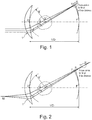
- Figure 1 illustrates the case of a perfect single vision ophthalmic lens calculated with a prescription determined for far vision.
- the light rays coming from the object M passing through the single vision ophthalmic lens focus farther behind the single vision ophthalmic lens than when the object M is at far distance, for example infinite.
- the optical system can rarely be considered as a centered optical system and Gauss approximation never apply. Therefore, the single vision ophthalmic lens cannot be considered as stigmatic and usual considerations as principal planes cannot be taken into account.
- a single vision ophthalmic lens is calculated to have mean power, astigmatism and axis in every gaze directions corresponding to the prescription values for objects proximity equal to proximity of the prescription determination, when the wearer gazes at objects at different distances the mean power, astigmatism and axis through the single vision ophthalmic lens vary from the prescription values and optical default of the single vision ophthalmic lens increase, causing blur vision and then discomfort or fatigue to the wearer.
- the present invention proposes a method, for example implemented by computer means, for determining a single vision ophthalmic lens adapted to a wearer.
- the method comprises at least:
- wearer prescription data providing step S1 wearer prescription data indicative of at least the prescribed optical power of the wearer are provided.
- the prescribed optical power is provided for a given gazing distance, preferably a far gazing distance, for example greater than or equal to 5 meters.
- the wearer prescription data may further be indicative of the prescribed astigmatism of the wearer.
- the wearer prescription data is further indicative of the prescribed astigmatism of the wearer, such prescribed astigmatism is provided for the same gazing distance as the prescribed optical power, preferably a far gazing distance, for example greater than or equal to 5 meters.
- wearing data providing step S2 wearing data indicative of the wearing parameters of the single vision ophthalmic lens by the wearer are provided.
- the wearing conditions are to be understood as the position of the ophthalmic lens with relation to the eye of a wearer, for example defined by a pantoscopic angle, a Cornea to lens distance, a Pupil-cornea distance, a centre of rotation of the eye (CRE) to pupil distance, a CRE to lens distance and a wrap angle.
- a pantoscopic angle for example defined by a pantoscopic angle, a Cornea to lens distance, a Pupil-cornea distance, a centre of rotation of the eye (CRE) to pupil distance, a CRE to lens distance and a wrap angle.
- the Cornea to lens distance is the distance along the visual axis of the eye in the primary position (usually taken to be the horizontal) between the cornea and the back surface of the lens; for example equal to 12mm.
- the Pupil-cornea distance is the distance along the visual axis of the eye between its pupil and cornea; usually equal to 2mm.
- the CRE to pupil distance is the distance along the visual axis of the eye between its center of rotation (CRE) and cornea; for example equal to 11.5mm.
- the CRE to lens distance is the distance along the visual axis of the eye in the primary position (usually taken to be the horizontal) between the CRE of the eye and the back surface of the lens, for example equal to 25.5mm.
- the pantoscopic angle is the angle in the vertical plane, at the intersection between the back surface of the lens and the visual axis of the eye in the primary position (usually taken to be the horizontal), between the normal to the back surface of the lens and the visual axis of the eye in the primary position; for example equal to -8°.
- the wrap angle is the angle in the horizontal plane, at the intersection between the back surface of the lens and the visual axis of the eye in the primary position (usually taken to be the horizontal), between the normal to the back surface of the lens and the visual axis of the eye in the primary position for example equal to 0°.
- An example of standard wearer condition may be defined by a pantoscopic angle of -8°, a Cornea to lens distance of 12 mm, a Pupil-cornea distance of 2 mm, a CRE to pupil distance of 11.5 mm, a CRE to lens distance of 25.5 mm and a wrap angle of 0°.
- the single vision ophthalmic lens determining step S4 the single vision ophthalmic lens is determined so that in wearing conditions corresponding to the wearing parameters, the single vision ophthalmic lens provides to the wearer the prescribed optical power in at least a first gazing direction when gazing at a first distance and a second gazing direction when gazing at a second distance.
- the first and second distances are different and the first and second gazing directions are different.
- the difference between the optical power provided to the wearer in the first direction when gazing at a first distance and the optical power provided in the second gazing direction when gazing at a second distance is smaller than or equal to 0.1 Diopters, for example substantially equal to 0 Diopter.
- the prescription data may further comprise data indicative of the prescribed astigmatism of the wearer and during the single vision ophthalmic lens determining step the single vision ophthalmic lens is determined so that in wearing conditions corresponding to the wearing parameters, the single vision ophthalmic lens provides to the wearer the prescribed astigmatism in at least the first gazing direction when gazing at the first distance and the second gazing direction when gazing at the second distance.
- the norm of the vector corresponding to the difference between the astigmatism provided to the wearer in the first direction when gazing at a first distance and the prescribed astigmatism is smaller than or equal to 0.1 Diopters, for example smaller than or equal to 0.05 Diopters.
- the norm of the vector corresponding to the difference between the astigmatism provided to the wearer is substantially equal to 0.0D.
- the norm of the vector corresponding to the difference between the astigmatism provided in the second gazing direction when gazing at a second distance and the prescribed astigmatism is smaller than or equal to 0.1 Diopters, for example smaller than or equal to 0.05 Diopters.
- the method of the invention is not limited to two gazing directions and may be implemented for a set of gazing directions, for example for all gazing directions.
- a set of gaze directions is associated to an object proximity which can be different for each gazing direction. For example, the fact that the closer the objects are the more the gaze lowering increase can be use to describe the environment object. The convergence of the eyes when looking at close objects can be also taken into account in the single vision ophthalmic lens determination.
- the eye care practitioner determines the needed power of the lens taking in account rays coming from infinite distance or at least distances greater than or equal to 5 meters.
- a single vision ophthalmic lens determined by a method of the invention provides to the wearer the right power to the wearer looking at objects at at least two different distances.
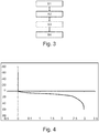
- Figure 4 is an example of a proximity graph that may be used in the method of the invention.
- Y axis gives the vertical angle in degrees for gaze direction in ⁇ directions relative to TABO referential.
- the angle between the first and the second gazing directions is greater than or equal to 5 deg, for example greater than or equal to 10 deg, for example greater than or equal to 15 deg, for example greater than or equal to 20 deg.
- the difference between the first and second distance is greater than or equal to 30 cm, for example greater than or equal to 1 meter, for example greater than or equal to 4 meters.
- the first distance corresponds to a far vision distance, for example greater than or equal to 5 meters.
- far vision distance or infinity corresponds to distance greater than or equal to 5 meters, for example greater than 5 meters.
- the first gazing direction may have an angle ⁇ greater than or equal to -16.0 deg and smaller than or equal to 8.0 deg and an angle ⁇ greater than or equal to -5.0 deg and smaller than or equal to 5.0 deg.
- Such first gazing direction advantageously combines with a first distance corresponding to far vision distance. Indeed, such gazing direction corresponds to the natural gazing direction when gazing at far distance.
- the second distance corresponds to a near vision distance, for example smaller than or equal to 4 meters, for example smaller than or equal to 1 meter, for example smaller than or equal to 40 cm.
- the second gazing direction may have an angle ⁇ greater than or equal to 5.0 deg and smaller than or equal to 36 deg and an angle ⁇ greater than or equal to -4.0 deg and smaller than or equal to 16.0 deg.
- Such second gazing direction advantageously combines with a second distance corresponding to near vision distance. Indeed, such gazing direction corresponds to the natural gazing direction when gazing at near distance.
- a single vision ophthalmic lenses configured so that the angle between the first and the second gazing directions is around 5 deg, with a first distance greater than 5 meters and second distance around 63 cm is particularly adapted for working on a computer screen.
- a single vision ophthalmic lenses configured so that the angle between the first and the second gazing directions is around 18 deg, with a first distance greater than 5 meters and a second distance around 40 cm is particularly adapted for reading or working on paper.
- a single vision ophthalmic lenses configured so that the angle between the first and the second gazing directions is around 20 deg, with a first distance greater than 5 meters and a second distance around 40 cm is particularly adapted for reading or working on a digital tablet.
- a single vision ophthalmic lenses configured so that the angle between the first and the second gazing directions is around 25 deg, with a first distance greater than 5 meters and a second distance lower than 40 cm is particularly adapted for using a smart phone.
- the method of the invention may further comprise prior to the single vision ophthalmic lens determining step S4, an optical surface data providing step S3.
- optical surface data providing step S3 optical surface data indicative of a finished surface of the single vision ophthalmic lens are provided.
- the finished surface is preferably the front surface, or object surface, of the single vision ophthalmic lens.
- the invention is not limited to such embodiment and the skilled person may adapt the invention having the finished surface be the back or rear surface of the single vision ophthalmic lens.
- the position and/or the shape of the surface opposite to the finished surface are/is determined.
- the invention also relates to a single vision ophthalmic lens adapted to a wearer having at least a prescribed optical power.
- the single vision ophthalmic lens of the invention provides to the wearer in standard wearing condition in at least a first gazing direction the prescribed optical power when gazing at a first distance and in at least a second gazing direction the prescribed optical power when gazing at a second distance, the first and second distance being different and the first and second gazing direction being different.
- the single vision ophthalmic lens of the invention is determined by the method of the invention.
- the wearer may have a prescribed astigmatism and the single vision ophthalmic lens provides to the wearer in standard wearing conditions in at least the first gazing direction the prescribed astigmatism when gazing at the first distance and in at least the second gazing direction the prescribed astigmatism when gazing at the second distance.
- the angle between the first and the second gazing directions is preferably greater than or equal to 5 deg, for example greater than or equal to 10 deg, for example greater than or equal to 15 deg, for example greater than or equal to 20 deg.
- the difference between the first and second distance may be greater than or equal to 30 cm, for example greater than or equal to 1 meter, for example greater than or equal to 4 meters.
- the first distance corresponds to a far vision distance, for example greater than or equal to 5 meters.
- the first gazing direction has an angle ⁇ greater than or equal to -16 deg, for example greater than or equal to -8 deg, and smaller than or equal to 8 deg, for example smaller than 0 deg, and an angle ⁇ greater than or equal to -5.0 deg, for example greater than or equal to -2.0 degand smaller than or equal to 5.0 deg, for example smaller than or equal to 2.0 deg.
- the second gazing distance corresponds to a near vision distance, for example smaller than or equal to 4.0 meters, for example smaller than or equal to 1.0 meter, for example smaller than or equal to 0.4 meter.
- the second gazing direction has an angle ⁇ greater than or equal to 5.0 deg, for example greater than or equal to 8.0 deg, for example greater than or equal to 16.0 deg and smaller than or equal to 36.0 deg, for example smaller than or equal to 32.deg, for example smaller than or equal to 28.0 deg and an angle ⁇ greater than or equal to -4.0 deg, for example greater than or equal to 0.0 deg and smaller than or equal to 16.0 deg.
- Figures 5 to 7 illustrate single vision ophthalmic lens determined using a prior art method.
- the single vision ophthalmic lens illustrated on figures 5 to 7 is determined for a wearer having a prescribed optical power of -4 diopters and a prescribed astigmatism of 0 diopters.
- the reference point on the single vision ophthalmic lens are:
- the wearing parameters are a pantoscopic angle of -8°, a wrap angle of 0° and an eye to lens distance of 12 mm.
- the objects are located at infinity, for each gaze direction objects proximity is then 0m -1 .
- Figure 5 illustrates the wearer mean power in diopters and resulting astigmatism in diopters along meridian line expressed in deg.
- the meridian line is defined as 3 segments:
- Figure 6 represents the wearer mean power in diopters according to ⁇ , ⁇ gaze directions in deg.
- Figure 7 represents the resulting astigmatism in diopters according to ⁇ , ⁇ gaze directions in deg.
- Table 1 represents the optical values at reference point when considering far distance objects.
- Table 1 Name ⁇ (deg) ⁇ (deg) Mean Power (D) Astigmatism (D) Center point 0.0 0.0 -4.00 0.00 Low point 0.0 -20.0 -3.93 0.06 FC 0.0 0.0 -4.00 0.00
- Wearer mean power at center point is -4.00 D. This value is suitable for a wearer looking at distance object.
- this traditional lens doesn't provide the right mean power to the wearer, when he is looking at near distance objects. Near distance objects can be take in account given their proximity.
- Table 2 provides optical values for the same traditional single vision ophthalmic lens when looking at near objects.
- Table 2 Name ⁇ (deg) ⁇ (deg) Mean Power (D) Astigmatism (D) Center point 0.0 0.0 -4.00 0.00 Low point 0.0 -20.0 -3.93 0.11 FC 0.0 0.0 -4.00 0.00
- Figures 8 to 10 illustrate single vision ophthalmic lens determined using a method of the invention.
- the single vision ophthalmic lens of the invention is determined for the same prescription as the prior art single vision ophthalmic lens.
- the reference point on the single vision ophthalmic lens of the invention are:
- the wearing parameters are the same as for the prior art single vision ophthalmic lens.
- the proximity table illustrated on figure 4 is used.
- Figure 8 illustrates the wearer mean power in diopters and resulting astigmatism in diopters along meridian line expressed in deg.
- Figure 9 represents the wearer mean power in diopters according to ⁇ , ⁇ gaze directions in deg.
- Figure 10 represents the resulting astigmatism in diopters according to ⁇ , ⁇ gaze directions in deg.
- Table 3 provides optical values for a single vision ophthalmic lens of the invention when looking at near objects.
- Table 3 Name ⁇ (deg) ⁇ (deg) Mean Power (D) Astigmatism (D) Center point 0.0 0.0 -4.00 0.00 Low point 4.8 -19.8 -4.00 0.02 FC 0.0 0.0 -4.00 0.00
Priority Applications (10)
| Application Number | Priority Date | Filing Date | Title |
|---|---|---|---|
| EP18305383.4A EP3547013A1 (de) | 2018-03-30 | 2018-03-30 | Verfahren zur bestimmung eines einstärkenbrillenglases |
| CN201980023432.5A CN111989611B (zh) | 2018-03-30 | 2019-03-28 | 用于确定单光眼科镜片的方法 |
| RU2020132217A RU2768516C1 (ru) | 2018-03-30 | 2019-03-28 | Способ подбора монофокальной офтальмологической линзы |
| EP19715048.5A EP3776067A1 (de) | 2018-03-30 | 2019-03-28 | Verfahren zur bestimmung eines einstärkenbrillenglases |
| PCT/EP2019/057951 WO2019185848A1 (en) | 2018-03-30 | 2019-03-28 | A method for determining a single vision ophthalmic lens |
| US17/043,223 US11892711B2 (en) | 2018-03-30 | 2019-03-28 | Method for determining a single vision ophthalmic lens |
| JP2020552856A JP7128904B2 (ja) | 2018-03-30 | 2019-03-28 | 単一視眼科レンズを決定する方法 |
| KR1020207027967A KR102522847B1 (ko) | 2018-03-30 | 2019-03-28 | 단초점 안구 렌즈를 결정하기 위한 방법 |
| CA3095519A CA3095519C (en) | 2018-03-30 | 2019-03-28 | A method for determining a single vision ophthalmic lens |
| BR112020019535-9A BR112020019535A2 (pt) | 2018-03-30 | 2019-03-28 | Método para determinação de uma lente oftálmica de visão única |
Applications Claiming Priority (1)
| Application Number | Priority Date | Filing Date | Title |
|---|---|---|---|
| EP18305383.4A EP3547013A1 (de) | 2018-03-30 | 2018-03-30 | Verfahren zur bestimmung eines einstärkenbrillenglases |
Publications (1)
| Publication Number | Publication Date |
|---|---|
| EP3547013A1 true EP3547013A1 (de) | 2019-10-02 |
Family
ID=61965885
Family Applications (2)
| Application Number | Title | Priority Date | Filing Date |
|---|---|---|---|
| EP18305383.4A Withdrawn EP3547013A1 (de) | 2018-03-30 | 2018-03-30 | Verfahren zur bestimmung eines einstärkenbrillenglases |
| EP19715048.5A Pending EP3776067A1 (de) | 2018-03-30 | 2019-03-28 | Verfahren zur bestimmung eines einstärkenbrillenglases |
Family Applications After (1)
| Application Number | Title | Priority Date | Filing Date |
|---|---|---|---|
| EP19715048.5A Pending EP3776067A1 (de) | 2018-03-30 | 2019-03-28 | Verfahren zur bestimmung eines einstärkenbrillenglases |
Country Status (9)
| Country | Link |
|---|---|
| US (1) | US11892711B2 (de) |
| EP (2) | EP3547013A1 (de) |
| JP (1) | JP7128904B2 (de) |
| KR (1) | KR102522847B1 (de) |
| CN (1) | CN111989611B (de) |
| BR (1) | BR112020019535A2 (de) |
| CA (1) | CA3095519C (de) |
| RU (1) | RU2768516C1 (de) |
| WO (1) | WO2019185848A1 (de) |
Cited By (1)
| Publication number | Priority date | Publication date | Assignee | Title |
|---|---|---|---|---|
| EP4197426A1 (de) | 2021-12-16 | 2023-06-21 | Essilor International | Verfahren zur bestimmung eines brillenglases und zugehörige optometrische vorrichtung |
Families Citing this family (1)
| Publication number | Priority date | Publication date | Assignee | Title |
|---|---|---|---|---|
| EP3985428A1 (de) | 2020-10-14 | 2022-04-20 | Essilor International | Computerimplementiertes verfahren zur bereitstellung eines fertiggestellten einstärkenbrillenglases |
Citations (5)
| Publication number | Priority date | Publication date | Assignee | Title |
|---|---|---|---|---|
| EP0990939A1 (de) * | 1998-09-28 | 2000-04-05 | Essilor International Compagnie Generale D'optique | Torische ophthalmische Linsen |
| FR2912820A1 (fr) * | 2007-02-15 | 2008-08-22 | Essilor Int | Realisation d'un element ophtalmique adapte pour les visions foveale et peripherique |
| EP2177943A1 (de) * | 2008-10-16 | 2010-04-21 | Essilor International (Compagnie Générale D'Optique) | Bestimmung eines optischen Systems anhand erweiterter Kriterien |
| WO2015150030A1 (en) * | 2014-04-01 | 2015-10-08 | Essilor International (Compagnie Generale D'optique) | Systems and methods for augmented reality |
| WO2016146590A1 (en) | 2015-03-18 | 2016-09-22 | Essilor International (Compagnie Générale d'Optique) | A method for determining an ophthalmic lens having unwanted astigmatism |
Family Cites Families (19)
| Publication number | Priority date | Publication date | Assignee | Title |
|---|---|---|---|---|
| US3969020A (en) * | 1973-12-28 | 1976-07-13 | Giles C. Clegg, Jr. | Automatic refraction apparatus and method |
| DE19960826A1 (de) | 1999-12-16 | 2001-07-05 | Rodenstock Optik G | Einstärken-Brillenglas mit Vollkorrektion |
| DE10338033A1 (de) | 2003-08-19 | 2005-03-31 | Rodenstock Gmbh | Individuelles Einstärkenbrillenglas |
| JP2008089618A (ja) | 2005-03-22 | 2008-04-17 | Nikon-Essilor Co Ltd | 眼鏡レンズ |
| EP2095174B1 (de) | 2006-12-22 | 2012-10-31 | ESSILOR INTERNATIONAL (Compagnie Générale d'Optique) | Verbesserte unifokal-brillenlinse |
| JP2008249828A (ja) | 2007-03-29 | 2008-10-16 | Nikon-Essilor Co Ltd | 眼鏡レンズおよびその設計方法 |
| FR2932577B1 (fr) * | 2008-06-12 | 2010-08-27 | Essilor Int | Realisation d'un verre ophtalmique progressif personnalise |
| FR2945874A1 (fr) * | 2009-05-20 | 2010-11-26 | Essilor Int | Lentille ophtalmique de type unifocale |
| FR2950983A1 (fr) * | 2009-10-01 | 2011-04-08 | Essilor Int | Procede de determination, d'optimisation et de fabrication d'une lentille ophtalmique et ensemble de lentilles ophtalmiques |
| DE102010021763A1 (de) | 2010-05-27 | 2011-12-01 | Carl Zeiss Vision Gmbh | Verfahren zum Herstellen eines Brillenglases sowie Brillenglas |
| JP2012233959A (ja) | 2011-04-28 | 2012-11-29 | Seiko Epson Corp | 眼鏡用レンズ、眼鏡、眼鏡レンズの設計方法、及び設計装置 |
| US8934166B2 (en) * | 2011-12-29 | 2015-01-13 | Elwha Llc | Customized user options for optical device |
| CN103424890A (zh) | 2013-08-21 | 2013-12-04 | 赵龙生 | 一种自然过渡、无盲区的广视角镜片 |
| DE102014206089B4 (de) | 2014-03-31 | 2018-01-18 | BSH Hausgeräte GmbH | Haushaltskältegerät mit einer Spendereinheit mit zwei Verschlusselementen an einem Ausführkanal |
| WO2016050664A1 (en) | 2014-09-30 | 2016-04-07 | Essilor International (Compagnie Generale D'optique) | A multifocal lens supply system for providing to a wearer a customized progressive spectacle ophthalmic lens |
| US10545355B2 (en) * | 2014-09-30 | 2020-01-28 | Essilor International | Spectacle ophthalmic lens, method for determining a spectacle ophthalmic lens |
| EP3037869A1 (de) * | 2014-12-23 | 2016-06-29 | Essilor International (Compagnie Generale D'optique) | Verfahren zum Vergleich einer ersten ophthalmischen Linse mit einer zweiten ophthalmischen Linse |
| EP3271778A1 (de) * | 2015-03-20 | 2018-01-24 | Essilor International | Ophthalmische linse und verfahren zur bestimmung davon |
| EP3079006B1 (de) | 2015-04-10 | 2019-06-12 | Essilor International | Brillenglas und verfahren zur bestimmung solch eines brillenglases |
-
2018
- 2018-03-30 EP EP18305383.4A patent/EP3547013A1/de not_active Withdrawn
-
2019
- 2019-03-28 WO PCT/EP2019/057951 patent/WO2019185848A1/en active Application Filing
- 2019-03-28 BR BR112020019535-9A patent/BR112020019535A2/pt unknown
- 2019-03-28 US US17/043,223 patent/US11892711B2/en active Active
- 2019-03-28 JP JP2020552856A patent/JP7128904B2/ja active Active
- 2019-03-28 RU RU2020132217A patent/RU2768516C1/ru active
- 2019-03-28 KR KR1020207027967A patent/KR102522847B1/ko active IP Right Grant
- 2019-03-28 CA CA3095519A patent/CA3095519C/en active Active
- 2019-03-28 EP EP19715048.5A patent/EP3776067A1/de active Pending
- 2019-03-28 CN CN201980023432.5A patent/CN111989611B/zh active Active
Patent Citations (5)
| Publication number | Priority date | Publication date | Assignee | Title |
|---|---|---|---|---|
| EP0990939A1 (de) * | 1998-09-28 | 2000-04-05 | Essilor International Compagnie Generale D'optique | Torische ophthalmische Linsen |
| FR2912820A1 (fr) * | 2007-02-15 | 2008-08-22 | Essilor Int | Realisation d'un element ophtalmique adapte pour les visions foveale et peripherique |
| EP2177943A1 (de) * | 2008-10-16 | 2010-04-21 | Essilor International (Compagnie Générale D'Optique) | Bestimmung eines optischen Systems anhand erweiterter Kriterien |
| WO2015150030A1 (en) * | 2014-04-01 | 2015-10-08 | Essilor International (Compagnie Generale D'optique) | Systems and methods for augmented reality |
| WO2016146590A1 (en) | 2015-03-18 | 2016-09-22 | Essilor International (Compagnie Générale d'Optique) | A method for determining an ophthalmic lens having unwanted astigmatism |
Cited By (1)
| Publication number | Priority date | Publication date | Assignee | Title |
|---|---|---|---|---|
| EP4197426A1 (de) | 2021-12-16 | 2023-06-21 | Essilor International | Verfahren zur bestimmung eines brillenglases und zugehörige optometrische vorrichtung |
Also Published As
| Publication number | Publication date |
|---|---|
| JP2021519447A (ja) | 2021-08-10 |
| CN111989611A (zh) | 2020-11-24 |
| WO2019185848A1 (en) | 2019-10-03 |
| CA3095519C (en) | 2024-03-12 |
| CA3095519A1 (en) | 2019-10-03 |
| JP7128904B2 (ja) | 2022-08-31 |
| US20210018763A1 (en) | 2021-01-21 |
| EP3776067A1 (de) | 2021-02-17 |
| KR102522847B1 (ko) | 2023-04-18 |
| BR112020019535A2 (pt) | 2021-01-05 |
| KR20200135970A (ko) | 2020-12-04 |
| US11892711B2 (en) | 2024-02-06 |
| CN111989611B (zh) | 2022-10-14 |
| RU2768516C1 (ru) | 2022-03-24 |
Similar Documents
| Publication | Publication Date | Title |
|---|---|---|
| US11016310B2 (en) | Method for determining a three dimensional performance of an ophthalmic lens; associated method of calculating an ophthalmic lens | |
| CN101317121B (zh) | 眼镜片 | |
| US7207675B1 (en) | Ophthalmic lens | |
| US9791718B2 (en) | Progressive multifocal ophthalmic lens designed to inhibit progressive myopia of the wearer | |
| EP3362842B1 (de) | Verfahren zur bereitstellung einer ophthalmischen progressiven zusatzlinse für einen normalsichtigen und altersweitsichtigen träger | |
| US11892711B2 (en) | Method for determining a single vision ophthalmic lens | |
| JP2012233933A (ja) | 視力矯正用レンズの設計方法 | |
| WO2019068586A1 (en) | METHOD FOR EVALUATING AN OPHTHALMIC LENS; ASSOCIATED ASSESSMENT SYSTEM AND INDUSTRIAL ASSEMBLY FOR MANUFACTURING AN OPHTHALMIC LENS | |
| JP2008299168A (ja) | 非球面眼鏡レンズ及び非球面眼鏡レンズの製造方法 | |
| US10394052B2 (en) | Method for determining a pair of ophthalmic lenses | |
| JP2022532028A (ja) | 装用者に適合する眼用累進多焦点レンズ | |
| JP2010107549A (ja) | 眼鏡レンズの設計方法、眼鏡レンズ及び眼鏡 | |
| US10656439B2 (en) | Lenses with improved management of distortion | |
| CN112334818B (zh) | 用于确定眼科镜片的方法 | |
| US20220004027A1 (en) | A progressive ophthalmic lens | |
| JP2007504485A (ja) | エラー対策を施したプログレッシブガラスの設計 |
Legal Events
| Date | Code | Title | Description |
|---|---|---|---|
| PUAI | Public reference made under article 153(3) epc to a published international application that has entered the european phase |
Free format text: ORIGINAL CODE: 0009012 |
|
| AK | Designated contracting states |
Kind code of ref document: A1 Designated state(s): AL AT BE BG CH CY CZ DE DK EE ES FI FR GB GR HR HU IE IS IT LI LT LU LV MC MK MT NL NO PL PT RO RS SE SI SK SM TR |
|
| AX | Request for extension of the european patent |
Extension state: BA ME |
|
| STAA | Information on the status of an ep patent application or granted ep patent |
Free format text: STATUS: THE APPLICATION IS DEEMED TO BE WITHDRAWN |
|
| 18D | Application deemed to be withdrawn |
Effective date: 20200603 |