EP3546860A1 - Haushaltsgerät mit einer an einem wandelement ausgebildeten justagekontur - Google Patents
Haushaltsgerät mit einer an einem wandelement ausgebildeten justagekontur Download PDFInfo
- Publication number
- EP3546860A1 EP3546860A1 EP19162593.8A EP19162593A EP3546860A1 EP 3546860 A1 EP3546860 A1 EP 3546860A1 EP 19162593 A EP19162593 A EP 19162593A EP 3546860 A1 EP3546860 A1 EP 3546860A1
- Authority
- EP
- European Patent Office
- Prior art keywords
- holding part
- wall element
- domestic appliance
- receiving space
- appliance according
- Prior art date
- Legal status (The legal status is an assumption and is not a legal conclusion. Google has not performed a legal analysis and makes no representation as to the accuracy of the status listed.)
- Granted
Links
Images





Classifications
-
- F—MECHANICAL ENGINEERING; LIGHTING; HEATING; WEAPONS; BLASTING
- F25—REFRIGERATION OR COOLING; COMBINED HEATING AND REFRIGERATION SYSTEMS; HEAT PUMP SYSTEMS; MANUFACTURE OR STORAGE OF ICE; LIQUEFACTION SOLIDIFICATION OF GASES
- F25D—REFRIGERATORS; COLD ROOMS; ICE-BOXES; COOLING OR FREEZING APPARATUS NOT OTHERWISE PROVIDED FOR
- F25D25/00—Charging, supporting, and discharging the articles to be cooled
- F25D25/02—Charging, supporting, and discharging the articles to be cooled by shelves
- F25D25/024—Slidable shelves
- F25D25/025—Drawers
-
- F—MECHANICAL ENGINEERING; LIGHTING; HEATING; WEAPONS; BLASTING
- F25—REFRIGERATION OR COOLING; COMBINED HEATING AND REFRIGERATION SYSTEMS; HEAT PUMP SYSTEMS; MANUFACTURE OR STORAGE OF ICE; LIQUEFACTION SOLIDIFICATION OF GASES
- F25D—REFRIGERATORS; COLD ROOMS; ICE-BOXES; COOLING OR FREEZING APPARATUS NOT OTHERWISE PROVIDED FOR
- F25D23/00—General constructional features
- F25D23/06—Walls
- F25D23/065—Details
- F25D23/066—Liners
-
- F—MECHANICAL ENGINEERING; LIGHTING; HEATING; WEAPONS; BLASTING
- F25—REFRIGERATION OR COOLING; COMBINED HEATING AND REFRIGERATION SYSTEMS; HEAT PUMP SYSTEMS; MANUFACTURE OR STORAGE OF ICE; LIQUEFACTION SOLIDIFICATION OF GASES
- F25D—REFRIGERATORS; COLD ROOMS; ICE-BOXES; COOLING OR FREEZING APPARATUS NOT OTHERWISE PROVIDED FOR
- F25D23/00—General constructional features
- F25D23/06—Walls
- F25D23/065—Details
- F25D23/067—Supporting elements
-
- F—MECHANICAL ENGINEERING; LIGHTING; HEATING; WEAPONS; BLASTING
- F25—REFRIGERATION OR COOLING; COMBINED HEATING AND REFRIGERATION SYSTEMS; HEAT PUMP SYSTEMS; MANUFACTURE OR STORAGE OF ICE; LIQUEFACTION SOLIDIFICATION OF GASES
- F25D—REFRIGERATORS; COLD ROOMS; ICE-BOXES; COOLING OR FREEZING APPARATUS NOT OTHERWISE PROVIDED FOR
- F25D25/00—Charging, supporting, and discharging the articles to be cooled
- F25D25/02—Charging, supporting, and discharging the articles to be cooled by shelves
- F25D25/024—Slidable shelves
-
- E—FIXED CONSTRUCTIONS
- E05—LOCKS; KEYS; WINDOW OR DOOR FITTINGS; SAFES
- E05Y—INDEXING SCHEME ASSOCIATED WITH SUBCLASSES E05D AND E05F, RELATING TO CONSTRUCTION ELEMENTS, ELECTRIC CONTROL, POWER SUPPLY, POWER SIGNAL OR TRANSMISSION, USER INTERFACES, MOUNTING OR COUPLING, DETAILS, ACCESSORIES, AUXILIARY OPERATIONS NOT OTHERWISE PROVIDED FOR, APPLICATION THEREOF
- E05Y2900/00—Application of doors, windows, wings or fittings thereof
- E05Y2900/30—Application of doors, windows, wings or fittings thereof for domestic appliances
- E05Y2900/31—Application of doors, windows, wings or fittings thereof for domestic appliances for refrigerators
-
- F—MECHANICAL ENGINEERING; LIGHTING; HEATING; WEAPONS; BLASTING
- F25—REFRIGERATION OR COOLING; COMBINED HEATING AND REFRIGERATION SYSTEMS; HEAT PUMP SYSTEMS; MANUFACTURE OR STORAGE OF ICE; LIQUEFACTION SOLIDIFICATION OF GASES
- F25D—REFRIGERATORS; COLD ROOMS; ICE-BOXES; COOLING OR FREEZING APPARATUS NOT OTHERWISE PROVIDED FOR
- F25D2500/00—Problems to be solved
- F25D2500/02—Geometry problems
Definitions
- the invention relates to a household appliance having a body as well as a receiving space located in the body and at least partially delimited by a wall element and having a holding part which is arranged on a side of the wall element facing away from the receiving space and which is coupled to an adjustment contour formed on the wall element and extends over the adjustment contour in a plane encompassing the wall element.
- Such a household appliance may for example be a refrigerator, a cooking appliance or a dishwasher. If the household appliance is a refrigerator, it may be a refrigerator, a freezer or a fridge-freezer combination.
- a refrigeration device with an outer housing and an inner container wherein a reinforcing element between the outer housing and the inner container is attached to the inner container and wherein a disposed within the inner container support member is fixed to the reinforcing element.
- the object of the present invention is to improve an aforementioned household appliance
- a household appliance according to the features of the independent claim. Accordingly, it is provided in a generic household appliance, that the Justagekontur facing away from the receiving space and in which the wall element comprehensive level has elongated projection. By the projection "elongated" is formed, this has at least one longitudinal extension which is greater than its other extensions (for example, width extension and height extension).
- the projection is remote from the receiving space, it is possible to form the Justagekontur such that it does not represent a spatial restriction of the receiving space.
- the available volume of the receiving space is not reduced and the accessibility of the receiving space, for example for the introduction of shelves, pull-out devices, bearings, etc., not impaired.
- the present invention is based on the recognition that the elongated formation of the projection in a reliable manner, a precise positioning of the holding part is made possible.
- the desired end position of the holding part can be done by a simple assembly step. Due to the resulting precise positioning of the holding part, it is again possible to arrange a to be fastened to the holding part insert precisely in terms of its position and especially its orientation in the receiving space.
- a better support of the holding part can be achieved by the elongated formation of the projection.
- weight forces can be reliably absorbed.
- a built-in part to be accommodated in the receiving space and to be fastened to the holding part, such as a pull-out arrangement, can thereby be held securely and reliably.
- the wall element limits the receiving space "at least in sections" it is to be understood in particular that the receiving space can also be limited by further wall elements.
- the wall element according to the invention may represent a side wall and the receiving space may be further limited by a bottom, a ceiling and a rear wall.
- the receiving space is arranged in a body of the household appliance and is closed or accessible by a closure element, for example door, drawer or flap.
- the body typically has an outer wall. Between the wall element according to the invention (and the possible further wall elements which bound the receiving space) and the outer wall, a cavity filled with thermal insulation material may be formed.
- the adjustment contour may comprise one or more further elements in addition to the projection. It is conceivable, for example, that the adjustment contour also has a projection facing the receiving space. According to one embodiment, however, it is provided that the adjustment contour is formed by the protrusion facing away from the receiving space and in a plane comprising the wall element elongated projection. In this case, therefore, the adjustment contour is finally formed by the projection, i. it does not include any other elements.
- the projection is solid.
- the projection represents an accumulation of material of the wall element.
- a recess facing the receiving space is formed by the projection. It is preferably provided that the size and / or the shape, in particular the spatial orientation, of the depression substantially corresponds to that of the projection.
- the projection has a substantially constant wall thickness, in particular a wall thickness substantially corresponding to the wall thickness of the wall element.
- the adjustment contour can be formed by a relative to the wall element separately formed component.
- the term "separately formed component” here and in the following means that the respective elements or components, in this case the adjustment contour and the wall element, are formed by components which are manufactured separately from one another and optionally connected to one another in a positive, non-positive and / or materially bonded manner are. According to one embodiment, however, it is provided that the adjustment contour is formed integrally with the wall element.
- integralally formed is here and below to understand that the two elements or Components (here Justagekontur and wall element) integral, in particular einstoffig, are produced in a manufacturing step.
- the Justagekontur can be formed in the manufacture or molding of the wall element. It is conceivable that the wall element including the Justagekontur is made by thermoforming and / or plastic.
- a longitudinal extent of the projection is arranged horizontally. This makes it possible that on the projection formed and horizontally arranged bearing surfaces which cooperate with support surfaces of the holding part, may have a maximum extent. A support of acting on the holding part weight forces can be optimized.
- the adjustment contour may be formed rib-shaped.
- the adjustment contour can be completely formed by a rib.
- the adjustment contour optionally also has other elements.
- the adjustment contour has at least one rib-shaped section.
- the rib-shaped portion is in particular elongated and has a longitudinal extent which runs parallel to the longitudinal extent of the adjustment contour. It is conceivable that the longitudinal extent of the rib-shaped section amounts to at least 50%, at least 70% or at least 80% of the longitudinal extent of the adjustment contour.
- the rib-shaped portion may have a constant cross-section along its longitudinal extent.
- enlargement sections are formed on end sections of the rib-shaped section.
- the enlargement sections are part of the adjustment contour.
- a height of the enlarging section measured from a surface of the wall element facing away from the receiving space is greater than a correspondingly measured height of the rib-shaped section.
- the projection thus extends farther away from the receiving space in the region of the enlargement section.
- a width of the enlargement section measured perpendicular to the longitudinal extent of the adjustment contour is greater than a width correspondingly measured width of the rib-shaped portion.
- the holding part may consist of two or more separately formed components. According to one embodiment, however, it is provided that the holding part is integrally formed.
- the holding part may be formed by a metal part, in particular it may be a stamped and bent part.
- the holding part may be formed thin-walled. It is conceivable in particular that the holding part has a substantially constant wall thickness.
- the holding part is elongated.
- the longitudinal extension of the holding part preferably corresponds at least to twice the value, at least four times the value or at least five times the value of the remaining extensions of the holding part.
- the holding part may be formed by a rail.
- the longitudinal extent of the holding part may be greater than the longitudinal extension of the adjustment contour.
- the longitudinal extension of the holding part can amount to at least 1.5 times, twice, or three times the longitudinal extent of the adjustment contour.
- the holding part can cover the adjustment contour on both sides along a direction extending along the longitudinal extension of the adjustment contour.
- the holding part can cover the adjustment contour on both sides along a direction perpendicular to the longitudinal extent of the alignment contour. With regard to the longitudinal extent, the holding part and the adjustment contour can run parallel.
- the holding part has a coupling portion, by means of which the holding part is positively and / or non-positively coupled to the Justagekontur. It is possible that acting on the holding part forces (in particular weight forces) are derived exclusively, substantially exclusively or at least partially via the coupling portion on the wall element.
- the coupling section has at least one bridge element and / or at least one opening.
- the bridge element may in particular be elongated.
- a breakthrough may in particular follow at an end portion of the bridge element.
- the bridge element can be formed with respect to its shape complementary to the projection or at least to a portion of the projection.
- the bridge element may be formed complementary to the rib-shaped portion.
- the holding part is elongated and extends the coupling portion only over a portion of a longitudinal extension of the holding part.
- the coupling portion may be arranged centrally with respect to the longitudinal extent of the holding part, whereby the mounting of the holding part is simplified to the Justagekontur.
- the coupling section is arranged eccentrically with respect to the longitudinal extension of the holding part. Due to the eccentric arrangement of the coupling section, positions for possible fastening sections on the holding part can moreover be selected more freely.
- the holding part is elongate and has at least two fastening sections spaced apart along its longitudinal extension, to which a mounting part arranged in the receiving space is fastened.
- the built-in part can be fastened by means of two adapter parts to the at least two fastening sections.
- the built-in part is formed in one piece and is fastened directly to the at least two fastening sections.
- the at least two attachment portions may be formed by a projection of the holding part.
- the two attachment portions may be formed like a dome.
- the two attachment portions may be formed by an embossed structure. In this way, the mechanical stability of the attachment portions can be increased.
- the fastening portions may each have a screw hole for fixing the fitting by means of a screw.
- the screw hole may in particular be formed in a cylindrical projection, so that despite a small wall thickness of the holding part a sufficient number of threads can be realized.
- the attachment portions may be formed separately from the coupling element to allow an optimal position for attachment of the mounting part.
- an overlap-free arrangement of coupling element and attachment portion conceivable (in a projection of the holding part on a plane comprising the wall element).
- the coupling section is arranged with respect to the longitudinal extent of the holding part between the at least two fastening sections.
- the wall element has at least two openings and each attachment portion is accessible through a breakthrough, starting from the receiving space. It is preferably provided that the openings are formed separately from each other and spaced from each other, in particular that each breakthrough is formed edge closed. The openings may be formed separately from the adjustment contour and spaced therefrom. If a fastening section is formed by a projection, it can be provided that the fastening section engages in the opening at least in sections. The mounting portion can thus be positioned closer to the receiving space, whereby the installation of a built-in part is simplified.
- a surface of the fastening section facing the receiving space may be flat and / or at least partially or completely flush with a surface of the wall element which surrounds or surrounds the opening.
- the attachment portion does not protrude into the receiving space via a surface of the wall element which surrounds the opening and which faces the receiving space.
- the holding part may preferably be arranged completely outside the receiving space.
- the holding part is elongated and arranged horizontally and that a built-in part arranged in the receiving space and fixed to the holding part is part of a pull-out device or represents such.
- a pull-out device for example a drawer front
- a closing element for example a drawer front
- the pull-out device which is visible even in the closed state by a user, can thus according to the invention in a simple manner a high-quality external appearance will be realized. Because possible gaps between the drawer front and other closure elements have reliably and precisely the desired dimensions.
- the projection is closed or to have a closed bottom.
- the projection has no breakthrough.
- the projection has one, two or more openings. In this way, an additional connection between the wall element and the holding part and / or the holding part and an additional fixing element can be made possible.
- the holding part and the wall element are screwed together.
- the adjusting contour has a recess facing the receiving space, in which there is a fixing element which is coupled to the holding part is.
- a fixing element which is coupled to the holding part is.
- the coupling can be positive and / or non-positive and / or cohesive.
- the fixing element can be locked to the holding part.
- the fixing element can be screwed to the holding part.
- the fixing element may be formed in one piece.
- the fixing element may be made of metal or plastic.
- the fixing element may be a plastic injection-molded component.
- the fixing element can fill the depression completely, partially or substantially completely.
- a surface of the fixing element facing the receiving space terminates flush with a surface of the wall element surrounding or enclosing the depression or with respect thereto Surface is set back. In this way, the fixing element is not disturbing with respect to mounting parts to be arranged in the receiving space.
- the fixing element can be supported by means of a support surface on a support surface of the recess. In this way, forces acting on the holding part (in particular weight forces in a horizontal arrangement of bearing surface and supporting surface) can also be transmitted to the wall element via the fixing element.
- the household appliance further comprises an adhesive, which contacts the holding part and the wall element.
- the adhesive may thus contribute to the attachment of the holding part with the wall element.
- the adhesive is not designed to absorb weight forces acting on the holding part during proper use of the household appliance.
- the adhesive may be designed to allow a prefixing of the holding part until it is sufficiently fixed, for example, by insulating material which is arranged on the surface of the wall element facing away from the receiving space.
- the adhesive may be adhesive tape or hot glue.
- the adhesive may further constitute a seal between the holding part and the wall element and / or a seal of openings of the wall element.
- the household appliance has at least one further wall element, which limits the receiving space at least in sections, and that the household appliance has at least one further holding part, which is arranged on a side facing away from the receiving space of the other wall element and which with a on the further wall element formed further adjustment contour is coupled.
- the further Justagekontur facing away from the receiving space and in a comprehensive the other wall element level elongated formed further projection. All the features or properties described for the wall element, the adjustment contour, the projection are also applicable to the further wall element, the further Justagekontur and the other projection.
- the wall element and the further wall element with respect to the Forming space opposite wall elements form (for example, left side wall and right side wall).
- the household appliance may be a refrigeration appliance, a cooking appliance or a dishwasher. If the household appliance is a refrigerator, it may be a refrigerator, a freezer or a fridge-freezer combination.
- the receiving space is formed by a cooling space and the wall element may be part of an inner container, in particular made of plastic.
- top, bottom, front, “rear”, “horizontal”, “vertical”, “depth direction”, “width direction”, “height direction” etc. are the intended use and proper arrangement of the household appliance and at a given then in front of the household appliance and looking in the direction of the home appliance given observer positions and orientations.
- Fig. 1 is a household appliance 1, shown in the form of a household refrigerator, which is designed for storing and preserving food.
- the household appliance 1 is in the embodiment, a refrigerator-freezer combination device.
- the household appliance 1 has a body 2, in which a plurality of separate receiving spaces for food are formed.
- a first receiving space 3 is formed, which is formed in the present embodiment as a cooling compartment.
- the domestic appliance 1 comprises a fresh storage compartment 4 formed in the height direction (Z direction) underneath, which constitutes a partial volume of the refrigerating compartment 3 and in which a different air humidity and / or a different temperature can be set to the remaining partial volume of the receiving space 3 lying above.
- the receiving space 3 can be closed by a plurality of separate, front-side arranged doors.
- the fresh-food compartment 4 can be closed in the context of a door 5, which is a front wall of a drawer which can be linearly displaced in the depth direction (Y-direction).
- the remaining partial volume of the receiving space 3 is closed by two further separate doors 6 and 7, which are pivotable about vertical axes and thus oriented in the vertical direction axes separately and independently of each other.
- the remaining partial volume of the receiving space 3, which is not formed by the fresh-food compartment 4 can be opened and closed independently of the fresh-food compartment 4 by means of this embodiment, which takes place by corresponding pivoting of the doors 6 and / or 7. Again, regardless of this, the fresh food compartment 4 can then be opened by the door 5 is opened and thus the drawer is pulled out.
- the household appliance 1 further comprises two further separate receiving spaces 8 and 9, which are freezers.
- the two freezers are also in turn closed by separate doors 10 and 11, wherein here, too, in the illustrated embodiment, these doors 10 and 11 are front walls of linearly displaceable drawers in the depth direction.
- the lower freezer compartment can be closed by the front wall of a drawer 12 designed as a door 11, this drawer 12 being shown here in the pulled-out state.
- the receiving spaces 3, 8 and 9 are limited by an inner container, which is in particular made of plastic, which inner container according to the illustrations in Fig. 2 , which shows a portion of the household appliance 1 in the region of the lower freezer compartment, oriented in the height direction side walls 13 and 14.
- an extraction device 15 which is a telescopic extension, is arranged on an inner side 14a of the wall element 14 which at least partially delimits the receiving space in the form of a side wall.
- a corresponding extension device is arranged, which in Fig. 2 but not visible.
- the drawer 12 is arranged at these drawers 15 which are oriented in the depth direction and can be displaced by means of these rail extension devices 15.
- a container 16 which is designed to hold the food.
- the built-in part 20, in particular in the form of the extension device 15, is provided with a separate holding part (in Fig. 2 not visible), which is formed of metal, attached to the wall element 14. Accordingly, this is in the extension device which is fixed to the wall element 13, is provided.
- a rail-shaped holding part 17 is arranged on an outer side 13b, which is opposite to an inner side 13a of the wall element 13.
- This outer side 13b faces away from the receiving space 9 and an outer wall 18 (FIG. Fig. 1 ), which is another component of the body 2, facing.
- a gap is formed in the thermally insulating material, in particular an insulating foam, is introduced.
- the adjustment contour 21 essentially has a constant wall thickness extending over the entire projection 22.
- the wall thickness substantially corresponds to the wall thickness of the wall element 14 outside the adjustment contour 21.
- the projection 22 extends in the width direction X of the receiving space 9 away.
- the projection 22 is formed on the side facing away from the receiving space 9 side 14 b of the wall element 14.
- a recess 23 complementary to the projection 22 in its shape and size is formed on the inner side 14 a of the wall element 14 facing the receiving space 9.
- the projection 22 is elongated.
- a longitudinal extension 24 is greater than a width extension 25 and greater than a height extension 26.
- the projection 22 is positioned such that its longitudinal extension 24 extends parallel to the depth direction Y.
- the projection 22 has a rib-shaped portion 27, which has a longitudinal extent 28 which is approximately 75% of the longitudinal extension 24 of the entire projection 22.
- enlarging portions 30 are integrally formed.
- the enlarging portions 30 extend beyond the rib-shaped portion 27 both in the width direction X and in the height direction Z. Accordingly, those portions of the recess 23 formed by the enlarging portions 30 are deeper and wider than that portion of the recess 23 formed by the rib-shaped portion 27.
- both the enlarging portions 30 have a greater height extent (corresponding to the height extent 26 of the entire protrusion) than that Height extension 32 of the rib-shaped portion 27th
- the adjustment contour 21 has two apertures 31 formed within the recess 23.
- the apertures 31 are both disposed entirely within the rib-shaped portion 27.
- the recess 23 has bearing surfaces 33,34.
- the bearing surfaces 33 are formed by boundary walls that portion of the recess 23 which is formed by the complementary shape of the enlargement portion 30.
- the support surface 34 is formed by a lateral boundary wall 35 of that portion of the recess 33 which is formed by the rib-shaped portion 27.
- the lateral boundary wall 35 and thus the support surface 34 is formed substantially horizontally.
- the size of the bearing surface 34 is greater than the sum of the surfaces of the bearing surfaces 33.
- the projection 22 has bearing surfaces 36,37.
- the wall element 14 also has three openings 38a, 38b, 38c.
- the adjustment contour 21 is arranged in the depth direction Y between two adjacent openings 38b, 38c.
- the adjustment contour 21 is formed without overlapping with the openings 38a, 38b, 38c.
- the openings 38a, 38b, 38c and the adjustment contour 21 are arranged substantially on a height level.
- the openings 38a, 38b, 38c are likewise arranged in the wall element 14, that is to say in the side wall.
- the wall element 14 merges integrally into a further wall element 39, which forms the bottom of the receiving space 9.
- Fig. 5 shows the arranged on the wall element 14 holding part 40.
- the one-piece and made of metal holding part 40 has a respect to its longitudinal extent 41 except centrally arranged coupling region 42.
- the coupling section 42 extends only over a partial section 65 of the longitudinal extension 42.
- the coupling section 42 comprises a bridge element 43 and two openings 45 arranged at its end sections 44.
- a support surface 46 is formed on the bridge element 43, which contacts the bearing surface 37 in the mounted state of the holding part 40 in order to apply weight forces acting on the holding part 40 transfer.
- the back member 43 further includes screw holes 47 formed in a cylinder shoulder 48.
- the holding part 40 further comprises three fastening portions 49, which are formed by projections 50 substantially.
- the projections 50 extend in the direction of the width direction X, that is to say in the direction of the receiving space 9 (see also FIG FIG. 7 ).
- the projections 50 are rotationally symmetrical and each have a centrally disposed screw hole 51, which is formed in a cylinder shoulder 52.
- the holding part 40 furthermore has two ribs 53, which are formed over the entire longitudinal extent 41 and project in the width direction X from a base plate 54.
- Fig. 6 shows the mounted on the inner container 19, in particular on the wall member 14 holding part 40. As can be seen, the bridge member 43 engages positively over the rib-shaped portion 27.
- the apertures 45 summarize the enlargement section 30 a.
- the adhesive 55 (shown in detail) is hot glue which can be applied over the entire edge portions of the holding part 40.
- the adhesive 56 (shown in detail) is adhesive tape which can be applied over the entire surface of the holding part 40 facing away from the wall element 14.
- a fixing element 58 (see also Fig. 8 ) arranged in the recess 23 .
- the fixing element 58 is connected to the holding part 40 by means of two screws 59, which penetrate the openings 31.
- the fixing element 58 on two bushings 60.
- a surface 61 of the one-piece and manufactured as a plastic injection molded fixing element 58 does not protrude into the receiving space 9. This surface 61 is rather set back in the width direction X with respect to the receiving space 9.
- the fixing element 58 comprises a rib-shaped center piece 62 and two cup-shaped widening pieces 64 formed on the end portions 63 thereof. In the assembled state, the fixing element 58 fills the recess 23 substantially completely. At the center piece 62, a support surface 66 is formed, with which the fixing element 58 can be supported on the support surface 34.
Landscapes
- Engineering & Computer Science (AREA)
- Chemical & Material Sciences (AREA)
- Combustion & Propulsion (AREA)
- Physics & Mathematics (AREA)
- Mechanical Engineering (AREA)
- Thermal Sciences (AREA)
- General Engineering & Computer Science (AREA)
- Cookers (AREA)
- Refrigerator Housings (AREA)
Abstract
Description
- Die Erfindung betrifft ein Haushaltsgerät mit einem Korpus sowie einem sich in dem Korpus befindlichen und durch ein Wandelement zumindest abschnittsweise begrenzten Aufnahmeraum und mit einem Halteteil, welches auf einer dem Aufnahmeraum abgewandten Seite des Wandelements angeordnet ist und welches mit einer an dem Wandelement ausgebildeten Justagekontur gekoppelt ist und sich in einer das Wandelement umfassenden Ebene über die Justagekontur erstreckt.
- Ein derartiges Haushaltsgerät kann beispielsweise ein Kältegerät, ein Gargerät oder ein Geschirrspülgerät sein. Sofern das Haushaltsgerät ein Kältegerät ist, kann es sich um einen Kühlschrank, einen Gefrierschrank oder eine Kühl-Gefrier-Kombination handeln.
- Bei derartigen Haushaltsgeräten werden oftmals Einbauteile, welche sich innerhalb des Aufnahmeraums befinden, an dem sich außerhalb des Aufnahmeraumes befindlichen Halteteil befestigt. Das Halteteil ermöglicht dabei eine stabilere Befestigung des Einbauteils.
- Aus der
WO 2011/080654 A2 ist ein Kältegerät mit einem Außengehäuse und einem Innenbehälter bekannt, wobei ein Verstärkungselement zwischen dem Außengehäuse und dem Innenbehälter an dem Innenbehälter befestigt ist und wobei ein innerhalb des Innenbehälters angeordnetes Tragelement an dem Verstärkungselement befestigt ist. - Die Aufgabe der vorliegenden Erfindung liegt darin, ein eingangs genanntes Haushaltsgerät zu verbessern
- Diese Aufgabe wird durch ein Haushaltsgerät gemäß den Merkmalen des unabhängigen Anspruchs gelöst. Demzufolge ist bei einem gattungsgemäßen Haushaltsgerät vorgesehen, dass die Justagekontur einen dem Aufnahmeraum abgewandten und in der das Wandelement umfassenden Ebene länglich ausgebildeten Vorsprung aufweist. Indem der Vorsprung "länglich" ausgebildet ist, weist dieser zumindest eine Längserstreckung auf, die größer ist als seine übrigen Erstreckungen (zum Beispiel Breitenerstreckung und Höhenerstreckung).
- Indem der Vorsprung dem Aufnahmeraum abgewandt ist, ist es möglich, die Justagekontur derart auszubilden, dass diese keine räumliche Beschränkung des Aufnahmeraumes darstellt. Insbesondere wird das zur Verfügung stehende Volumen des Aufnahmeraumes nicht verringert und die Zugänglichkeit des Aufnahmeraumes, zum Beispiel zum Einbringen von Fachböden, Auszugsvorrichtungen, Lagerschalen etc., nicht beeinträchtigt.
- Die vorliegende Erfindung beruht auf der Erkenntnis, dass durch die längliche Ausbildung des Vorsprungs auf zuverlässige Weise eine präzise Positionierung des Halteteils ermöglicht wird. Durch die Kopplung des Halteteils mit der Justagekontur und insbesondere mit dem Vorsprung kann die gewünschte Endposition des Halteteils durch einen einfachen Montageschritt erfolgen. Durch die sich hieraus ergebende präzise Positionierung des Halteteils ist es wiederum möglich, ein an dem Halteteil zu befestigendes Einbauteil präzise hinsichtlich seiner Position und vor allem seiner Ausrichtung in dem Aufnahmeraum anzuordnen.
- Darüber hinaus kann durch die längliche Ausbildung des Vorsprungs eine bessere Abstützung des Halteteils erreicht werden. Insbesondere auf das Halteteil einwirkende Gewichtskräfte können zuverlässig aufgenommen werden. Ein in dem Aufnahmeraum aufzunehmendes und an dem Halteteil zu befestigendes Einbauteil, wie zum Beispiel eine Auszugsanordnung, kann dadurch sicher und zuverlässig gehalten werden.
- Unter der Wendung, dass das Wandelement den Aufnahmeraum "zumindest abschnittsweise" begrenzt, ist insbesondere zu verstehen, dass der Aufnahmeraum auch durch weitere Wandelemente begrenzt werden kann. Beispielsweise kann das erfindungsgemäße Wandelement eine Seitenwand darstellen und der Aufnahmeraum kann weiterhin durch einen Boden, eine Decke und eine Rückwand begrenzt sein.
- Ausführungsformen der vorliegenden Erfindung sind in den abhängigen Ansprüchen angegeben.
- Typischerweise ist der Aufnahmeraum in einem Korpus des Haushaltsgeräts angeordnet und ist durch ein Verschlusselement, zum Beispiel Tür, Schublade oder Klappe, verschließbar bzw. zugänglich. Der Korpus weist typischerweise eine Außenwandung auf. Zwischen dem erfindungsgemäßen Wandelement (und den möglichen weiteren Wandelementen, die den Aufnahmeraum begrenzen) und der Außenwandung kann ein mit thermischen Isolationsmaterial gefüllter Hohlraum gebildet sein.
- Grundsätzlich möglich ist, dass die Justagekontur zusätzlich zu dem Vorsprung ein oder mehrere weitere Elemente umfasst. Denkbar ist zum Beispiel, dass die Justagekontur auch einen dem Aufnahmeraum zugewandten Vorsprung aufweist. Gemäß einer Ausführungsform ist jedoch vorgesehen, dass die Justagekontur durch den dem Aufnahmeraum abgewandten und in einer das Wandelement umfassenden Ebene länglich ausgebildeten Vorsprung gebildet ist. In diesem Fall wird somit die Justagekontur durch den Vorsprung abschließend gebildet, d.h. sie umfasst keine weiteren Elemente.
- Grundsätzlich möglich ist, dass der Vorsprung massiv ausgebildet ist. In diesem Fall stellt der Vorsprung eine Materialanhäufung des Wandelements dar. Um jedoch eine einfache und kostengünstige Fertigung zu ermöglichen, ist gemäß einer Ausführungsform vorgesehen, dass durch den Vorsprung eine dem Aufnahmeraum zugewandte Vertiefung ausgebildet ist. Vorzugsweise ist vorgesehen, dass die Größe und/oder die Form, insbesondere die räumliche Orientierung, der Vertiefung im Wesentlichen der des Vorsprungs entspricht. Insbesondere kann vorgesehen sein, dass der Vorsprung im Wesentlichen eine konstante Wandstärke aufweist, insbesondere eine im Wesentlichen der Wandstärke des Wandelements entsprechende Wandstärke.
- Die Justagekontur kann durch ein gegenüber dem Wandelement separat ausgebildetes Bauteil gebildet sein. Unter "separat ausgebildetes Bauteil" ist hierbei und im Folgenden zu verstehen, dass die jeweiligen Elemente bzw. Bauteile, in diesem Fall die Justagekontur und das Wandelement, durch separat voneinander hergestellte Bauteile gebildet sind, die gegebenenfalls miteinander formschlüssig, kraftschlüssig und/oder stoffschlüssig verbunden sind. Gemäß einer Ausführung vom ist jedoch vorgesehen, dass die Justagekontur einstückig mit dem Wandelement ausgebildet ist. Unter "einstückig ausgebildet" ist hierbei und im Folgenden zu verstehen, dass die beiden Elemente bzw. Bauteile (hier Justagekontur und Wandelement) integral, insbesondere einstoffig, in einem Fertigungsschritt hergestellt sind. Insbesondere kann die Justagekontur bei der Herstellung bzw. Ausformung des Wandelements ausgebildet werden. Denkbar ist, dass das Wandelement inklusive der Justagekontur durch Thermoformen und/oder aus Kunststoff hergestellt ist.
- Gemäß einer Ausführung vom ist vorgesehen, dass eine Längserstreckung des Vorsprungs horizontal angeordnet ist. Hierdurch wird ermöglicht, dass an dem Vorsprung gebildete und horizontal angeordnete Auflageflächen, welche mit Abstützflächen des Halteteils zusammenwirken, eine maximale Erstreckung aufweisen können. Eine Abstützung von auf das Halteteil einwirkenden Gewichtskräften kann optimiert werden.
- Die Justagekontur kann rippenförmig ausgebildet sein. Insbesondere kann die Justagekontur vollständig durch eine Rippe gebildet sein. Denkbar ist jedoch auch, dass die Justagekontur gegebenenfalls auch weitere Elemente aufweist. Gemäß einer Ausführungsform ist vorgesehen, dass die Justagekontur zumindest einen rippenförmigen Abschnitt aufweist. Der rippenförmige Abschnitt ist insbesondere länglich ausgebildet und weist eine Längserstreckung auf, die parallel zu der Längserstreckung der Justagekontur verläuft. Denkbar ist, dass die Längserstreckung des rippenförmigen Abschnitts zumindest 50 %, zumindest 70 % oder zumindest 80 % der Längserstreckung der Justagekontur beträgt. Der rippenförmige Abschnitt kann entlang seiner Längserstreckung einen konstanten Querschnitt aufweisen.
- Gemäß einer Ausführungsform ist vorgesehen, dass an Endabschnitten des rippenförmigen Abschnitts Vergrößerungsabschnitte angeformt sind. Die Vergrößerungsabschnitte sind Teil der Justagekontur.
- Gemäß einer Ausführungsform ist vorgesehen, dass eine ausgehend von einer dem Aufnahmeraum abgewandten Oberfläche des Wandelements gemessene Höhe des Vergrößerungsabschnitts größer ist, als eine entsprechend gemessene Höhe des rippenförmigen Abschnitts. Der Vorsprung erstreckt sich somit im Bereich des Vergrößerungsabschnitts weiter von dem Aufnahmeraum weg. Gemäß einer Ausführungsform ist vorgesehen, dass eine senkrecht zur Längserstreckung der Justagekontur gemessene Breite des Vergrößerungsabschnitts größer ist, als eine entsprechend gemessene Breite des rippenförmigen Abschnitts. Derartige Ausbildungen des Vergrößerungsabschnitts ermöglichen nochmals eine bessere Positionierung des Halteteils an der Justagekontur.
- Das Halteteil kann aus zwei oder mehreren separat voneinander ausgebildeten Bauteilen bestehen. Gemäß einer Ausführungsform ist jedoch vorgesehen, dass das Halteteil einstückig ausgebildet ist. Das Halteteil kann durch ein Metallteil gebildet sein insbesondere kann es sich um ein Stanz-Biege-Teil handeln. Das Halteteil kann dünnwandig ausgebildet sein. Denkbar ist insbesondere, dass das Halteteil eine im Wesentlichen konstante Wandstärke aufweist.
- Gemäß einer Ausführungsform ist vorgesehen, dass das Halteteil länglich ausgebildet ist. Vorzugsweise entspricht die Längserstreckung des Halteteils zumindest dem 2-fachen Wert, zumindest dem 4-fachen Wert oder zumindest dem 5-fachen Wert der übrigen Erstreckungen des Halteteils. Das Halteteil kann durch eine Schiene gebildet sein. Die Längserstreckung des Halteteils kann größer sein als die Längserstreckung der Justagekontur. Insbesondere kann die Längserstreckung des Halteteils wenigstens dem 1,5-fachen, dem 2-fachen, oder dem 3-fachen der Längserstreckung der Justagekontur betragen. Das Halteteil kann die Justagekontur entlang einer die Längserstreckung der Justagekontur verlaufenden Richtung beidseitig überdecken. Das Halteteil kann die Justagekontur entlang einer senkrecht zur Längserstreckung der Justagekontur verlaufenden Richtung beidseitig überdecken. Bezüglich der Längserstreckungen können das Halteteil und die Justagekontur parallel verlaufen.
- Gemäß einer Ausführungsform ist vorgesehen, dass das Halteteil einen Koppelabschnitt aufweist, mittels welchem das Halteteil formschlüssig und/oder kraftschlüssig mit der Justagekontur gekoppelt ist. Möglich ist, dass auf das Halteteil einwirkende Kräfte (insbesondere Gewichtskräfte) ausschließlich, im Wesentlichen ausschließlich oder zumindest teilweise über den Koppelabschnitt auf das Wandelement abgeleitet werden.
- Gemäß einer Ausführungsform ist vorgesehen, dass der Koppelabschnitt zumindest ein Brückenelement und/oder zumindest einen Durchbruch aufweist. Das Brückenelement kann insbesondere länglich ausgebildet sein. Ein Durchbruch kann sich insbesondere an einem Endabschnitt des Brückenelements anschließen. Das Brückenelement kann bezüglich seiner Form komplementär zu dem Vorsprung oder zumindest zu einem Teilabschnitt des Vorsprungs ausgebildet sein. Insbesondere kann das Brückenelement komplementär zu dem rippenförmigen Abschnitt ausgebildet sein.
- Gemäß einer Ausführungsform ist vorgesehen, dass das Halteteil länglich ausgebildet ist und sich der Koppelabschnitt nur über einen Teilabschnitt einer Längenerstreckung des Halteteils erstreckt. Der Koppelabschnitt kann bezüglich der Längserstreckung des Halteteils mittig angeordnet sein, wodurch die Montage des Halteteils an der Justagekontur vereinfacht wird. Um jedoch insbesondere bezüglich der Längserstreckung asymmetrisch angeordnete Elemente des Halteteils (zum Beispiel Befestigungsabschnitte für ein Bauteil) zuverlässig und fehlerfrei zu positionieren, kann vorgesehen sein, dass der Koppelabschnitt bezüglich der Längserstreckung des Halteteils außermittig angeordnet ist. Durch die außermittige Anordnung des Koppelabschnitts können darüber hinaus Positionen für mögliche Befestigungsabschnitte an dem Halteteil freier gewählt werden.
- Gemäß einer Ausführungsform ist vorgesehen, dass das Halteteil länglich ausgebildet ist und wenigstens zwei entlang seiner Längserstreckung voneinander beabstandete Befestigungsabschnitte aufweist, an denen ein in dem Aufnahmeraum angeordnetes Einbauteil befestigt ist. Das Einbauteil kann mittels zweier Adapterteile an den wenigstens zwei Befestigungsabschnitten befestigt sein. Insbesondere kann jedoch vorgesehen sein, dass das Einbauteil einstückig ausgebildet ist und direkt an den wenigstens zwei Befestigungsabschnitten befestigt ist. Die wenigstens zwei Befestigungsabschnitte können durch einen Vorsprung des Halteteils gebildet sein. Insbesondere können die zwei Befestigungsabschnitte domartig ausgebildet sein. Die zwei Befestigungsabschnitte können durch eine Prägestruktur gebildet sein. Auf diese Weise kann die mechanische Stabilität der Befestigungsabschnitte erhöht werden. Die Befestigungsabschnitte können jeweils ein Schraubloch zur Befestigung des Einbauteiles mittels einer Schraube aufweisen. Das Schraubloch kann insbesondere in einem Zylinderansatz gebildet sein, sodass trotz einer geringen Wandstärke des Halteteils eine ausreichende Anzahl von Gewindegängen realisierbar ist.
- Die Befestigungsabschnitte können separat von dem Koppelelement ausgebildet sein, um eine optimale Position zur Befestigung des Einbauteiles zu ermöglichen. Insbesondere ist eine überlappungsfreie Anordnung von Koppelelement und Befestigungsabschnitt denkbar (bei einer Projektion des Halteteils auf eine das Wandelement umfassende Ebene). Gemäß einer Ausführungsform ist vorgesehen, dass der Koppelabschnitt bezüglich der Längserstreckung des Halteteils zwischen den wenigstens zwei Befestigungsabschnitten angeordnet ist.
- Gemäß einer Ausführungsform ist vorgesehen, dass das Wandelement mindestens zwei Durchbrüche aufweist und jeder Befestigungsabschnitt durch einen Durchbruch ausgehend von dem Aufnahmeraum zugänglich ist. Vorzugsweise ist vorgesehen, dass die Durchbrüche separat voneinander ausgebildet und beabstandet zueinander angeordnet sind, insbesondere dass jeder Durchbruch randgeschlossen ausgebildet ist. Die Durchbrüche können separat zur Justagekontur ausgebildet und beabstandet zu dieser angeordnet sein. Sofern ein Befestigungsabschnitt durch einen Vorsprung gebildet ist, kann vorgesehen sein, dass der Befestigungsabschnitt zumindest abschnittsweise in den Durchbruch eingreift. Der Befestigungsabschnitt kann somit näher zu dem Aufnahmeraum positioniert werden, wodurch die Montage eines Einbauteiles vereinfacht wird. Insbesondere kann vorgesehen sein, dass eine dem Aufnahmeraum zugewandte Oberfläche des Befestigungsabschnitts eben ausgebildet ist und/oder zumindest abschnittsweise oder komplett bündig mit einer den Durchbruch umgebenden bzw. einfassenden Oberfläche des Wandelements ausgebildet ist. Insbesondere kann vorgesehen sein, dass der Befestigungsabschnitt nicht über eine den Durchbruch umgebende und dem Aufnahmeraum zugewandte Oberfläche des Wandelements in den Aufnahmeraum ragt. Das Halteteil kann vorzugsweise vollständig außerhalb des Aufnahmeraumes angeordnet sein.
- Gemäß einer Ausführungsform ist vorgesehen, dass das Halteteil länglich ausgebildet und waagrecht angeordnet ist und dass ein in dem Aufnahmeraum angeordnetes und an dem Halteteil befestigtes Einbauteil Bestandteil einer Auszugsvorrichtung ist oder eine solche darstellt. Erfindungsgemäß kann somit einerseits eine äußerst präzise Ausrichtung der Auszugsvorrichtung und andererseits eine stabile Befestigung der Auszugsvorrichtung ermöglicht werden. Insbesondere sofern an der Auszugsvorrichtung ein Verschlusselement (zum Beispiel eine Schubladenfront) des Aufnahmeraums angeordnet ist, welches auch im geschlossenen Zustand von einem Benutzer sichtbar ist, kann somit erfindungsgemäß auf einfache Art und Weise ein hochwertiges äußeres Erscheinungsbild realisiert werden. Denn mögliche Spalte zwischen der Schubladenfront und weiteren Verschlusselementen weisen zuverlässig und präzise die gewünschten Maße auf.
- Gemäß einer Ausführungsform vorgesehen, dass der Vorsprung geschlossen ausgebildet ist bzw. einen geschlossenen Boden aufweist. Insbesondere kann vorgesehen sein, dass der Vorsprung keinen Durchbruch aufweist. Denkbar ist jedoch auch, dass der Vorsprung einen, zwei oder mehrere Durchbrüche aufweist. Auf diese Weise kann eine zusätzliche Verbindung zwischen dem Wandelement und dem Halteteil und/oder dem Halteteil und einem zusätzlichen Fixierelement ermöglicht werden.
- Gemäß einer Ausführungsform ist vorgesehen, dass das Halteteil und das Wandelement, vorzugsweise im Bereich der Justagekontur, miteinander verschraubt sind.
- Alleine bereits durch die Kopplung des Halteteils mit der Justagekontur können die erfindungsgemäßen Vorteile erzielt werden. Um die Positionierung des Halteteils sowie auch um die Übertragung von auf das Halteteil einwirkenden Gewichtskräften nochmals zu verbessern, kann jedoch gemäß einer Ausführungsform vorgesehen sein, dass die Justagekontur eine dem Aufnahmeraum zugewandte Vertiefung aufweist, in der sich ein Fixierelement befindet, welches mit dem Halteteil gekoppelt ist. Für die Kopplung zwischen dem Fixierelement und dem Halteteil können ein, zwei oder mehrere Durchbrüche in dem Vorsprung ausgebildet sein. Die Kopplung kann formschlüssig und/oder kraftschlüssig und/oder stoffschlüssig erfolgen. Beispielsweise kann das Fixierelement mit dem Halteteil verrastet sein. Um eine sichere und belastbare Kopplung zu gewährleisten, kann das Fixierelement mit dem Halteteil verschraubt sein.
- Das Fixierelement kann einstückig ausgebildet sein. Das Fixierelement kann aus Metall oder Kunststoff bestehen. Insbesondere kann das Fixierelement ein Kunststoff-Spritzgussbauteil sein.
- Das Fixierelement kann die Vertiefung vollständig, teilweise oder im Wesentlichen vollständig ausfüllen. Insbesondere kann vorgesehen sein, dass eine dem Aufnahmeraum zugewandte Oberfläche des Fixierelements bündig mit einer die Vertiefung umgebenden bzw. einfassenden Oberfläche des Wandelements abschließt oder bezüglich dieser Oberfläche zurückversetzt ist. Auf diese Weise ist das Fixierelement bezüglich in dem Aufnahmeraum anzuordnenden Einbauteilen nicht störend.
- Das Fixierelement kann sich mittels einer Abstützfläche auf einer Auflagefläche der Vertiefung abstützen. Auf diese Weise können auf das Halteteil einwirkende Kräfte (insbesondere Gewichtskräfte bei einer horizontalen Anordnung von Auflagefläche und Abstützfläche) auch über das Fixierelement auf das Wandelement übertragen werden.
- Gemäß einer Ausführungsform weist das Haushaltsgerät weiterhin ein Klebemittel auf, welches das Halteteil und das Wandelement kontaktiert. Das Klebemittel kann somit zur Befestigung des Halteteils mit dem Wandelement beitragen. Vorzugsweise ist das Klebemittel jedoch nicht dazu ausgebildet, auf das Halteteil einwirkende Gewichtskräfte während einer bestimmungsgemäßen Benutzung des Haushaltsgeräts aufzunehmen. Vielmehr kann das Klebemittel dazu ausgebildet sein, eine Vorfixierung des Halteteil ist zu ermöglichen, bis dieses zum Beispiel durch Isolationsmaterial, welches auf der dem Aufnahmeraum abgewandten Oberfläche des Wandelements angeordnet wird, ausreichend fixiert wird. Bei dem Klebemittel kann es sich um Klebeband oder um Heißkleber handeln. Das Klebemittel kann weiterhin eine Abdichtung zwischen dem Halteteil und dem Wandelement und/oder eine Abdichtung von Durchbrüchen des Wandelements darstellen.
- Gemäß einer Ausführungsform ist vorgesehen, dass das Haushaltsgerät wenigstens ein weiteres Wandelement aufweist, welches den Aufnahmeraum zumindest abschnittsweise begrenzt, und dass das Haushaltsgerät wenigstens ein weiteres Halteteil aufweist, welches auf einer dem Aufnahmeraum abgewandten Seite des weiteren Wandelements angeordnet ist und welches mit einer an dem weiteren Wandelement ausgebildeten weiteren Justagekontur gekoppelt ist. Vorzugsweise ist dabei vorgesehen dass die weitere Justagekontur einen dem Aufnahmeraum abgewandten und in einer das weitere Wandelement umfassenden Ebene länglich ausgebildeten weiteren Vorsprung aufweist. Sämtliche für das Wandelement, die Justagekontur den Vorsprung beschriebenen Merkmale bzw. Eigenschaften sind dabei auch für das weitere Wandelement, die weitere Justagekontur und den weiteren Vorsprung anwendbar. Insbesondere kann vorgesehen sein, dass das Wandelement und das weitere Wandelement bezüglich des Aufnahmeraums gegenüberliegende Wandelemente bilden (zum Beispiel linke Seitenwand und rechte Seitenwand).
- Das Haushaltsgerät kann ein Kältegerät, ein Gargerät oder ein Geschirrspülgerät sein. Sofern das Haushaltsgerät ein Kältegerät ist, kann es sich um einen Kühlschrank, einen Gefrierschrank oder eine Kühl-Gefrier-Kombination handeln. Im Falle eines Kältegerätes wird der Aufnahmeraum durch einen Kühlraum gebildet und das Wandelement kann Teil eines insbesondere aus Kunststoff bestehenden Innenbehälters sein.
- Mit Angaben "oben", "unten", "vorne", "hinten, "horizontal", "vertikal", "Tiefenrichtung", "Breitenrichtung", "Höhenrichtung" etc. sind die bei bestimmungsgemäßen Gebrauch und bestimmungsgemäßem Anordnen des Haushaltsgerätes und bei einem dann vor dem Haushaltsgerätes stehenden und in Richtung des Haushaltsgerätes blickenden Beobachters gegebenen Positionen und Orientierungen angegeben.
- Ein Ausführungsbeispiel der vorliegenden Erfindung wird anhand der beigefügten Figuren erläutert. Dabei zeigen:
- Fig. 1
- eine schematische, perspektivische Darstellung eines erfindungsgemäßen Haushaltsgeräts;
- Fig. 2
- eine perspektivische Teildarstellung des Haushaltsgeräts gemäß
Fig. 1 ; - Fig. 3
- eine perspektivische Teildarstellung eines Innenbehälters des Haushaltsgeräts aus
Fig. 1 vom Aufnahmeraum betrachtet; - Fig. 4
- eine perspektivische Teildarstellung des Innenbehälters aus
Fig. 3 von dessen Rückseite betrachtet; - Fig. 5
- eine perspektivische Darstellung eines Halteteils;
- Fig. 6
- eine zu
Fig. 4 vergleichbare Darstellung mit montiertem Halteteil; - Fig. 7
- eine zu
Fig. 3 vergleichbare Darstellung mit montiertem Halteteil und montiertem Fixierelement; und - Fig. 8
- ein Fixierelement.
- In den Figuren werden gleiche oder funktionsgleiche Elemente mit den gleichen Bezugszeichen versehen.
- In
Fig. 1 ist ein Haushaltsgerät 1, in Form eines Haushaltskältegeräts, gezeigt, welches zum Lagern und Konservieren von Lebensmitteln ausgebildet ist. Das Haushaltsgerät 1 ist im Ausführungsbeispiel ein Kühl-Gefrier-Kombigerät. Das Haushaltsgerät 1 weist einen Korpus 2 auf, in dem mehrere separate Aufnahmeräume für Lebensmittel ausgebildet sind. In dem Zusammenhang ist ein erster Aufnahmeraum 3 ausgebildet, der im vorliegenden Ausführungsbeispiel als Kühlfach ausgebildet ist. Darüber hinaus umfasst das Haushaltsgerät 1 ein in Höhenrichtung (Z-Richtung) darunter ausgebildetes Frischhaltefach 4, welches ein Teilvolumen des Kühlfachs 3 darstellt und in welchem eine unterschiedliche Luftfeuchte und/oder eine unterschiedliche Temperatur zum darüber liegenden restlichen Teilvolumen des Aufnahmeraums 3 einstellbar ist. - Im Ausführungsbeispiel ist vorgesehen, dass der Aufnahmeraum 3 durch mehrere separate, frontseitige angeordnete Türen verschließbar ist. Das Frischhaltefach 4 ist in dem Zusammenhang mit einer Tür 5 verschließbar, die eine Frontwand einer in Tiefenrichtung (Y-Richtung) linear verschiebbaren Schublade ist. Das restliche Teilvolumen des Aufnahmeraums 3 ist durch zwei weitere separate Türen 6 und 7 verschließbar, die um vertikale Achsen und somit in Höhenrichtung orientierte Achsen separat und unabhängig voneinander verschwenkbar sind. Durch diese Ausgestaltung kann einerseits das restliche Teilvolumen des Aufnahmeraums 3, welches nicht durch das Frischhaltefach 4 gebildet ist, unabhängig von dem Frischhaltefach 4 geöffnet und geschlossen werden, was durch entsprechendes Verschwenken der Türen 6 und/oder 7 erfolgt. Wiederum davon unabhängig kann dann das Frischhaltefach 4 geöffnet werden, indem die Tür 5 geöffnet wird und somit die Schublade herausgezogen wird.
- Das Haushaltsgerät 1 umfasst darüber hinaus zwei weitere separate Aufnahmeräume 8 und 9, die Gefrierfächer sind.
- Die beiden Gefrierfächer sind ebenfalls wiederum durch separate Türen 10 und 11 verschließbar, wobei auch hier im gezeigten Ausführungsbeispiel diese Türen 10 und 11 Frontwände von in Tiefenrichtung linear verschiebbaren Schubläden sind. So ist beispielhaft gezeigt, dass das untere Gefrierfach durch die als Tür 11 ausgebildete Frontwand einer Schublade 12 verschließbar ist, wobei diese Schublade 12 hier in herausgezogenem Zustand gezeigt ist.
- Die Aufnahmeräume 3, 8 und 9 sind durch einen Innenbehälter, der insbesondere aus Kunststoff ausgebildet ist, begrenzt, wobei dieser Innenbehälter entsprechend den Darstellungen in
Fig. 2 , die einen Teilbereich des Haushaltsgeräts 1 im Bereich des unteren Gefrierfachs zeigt, in Höhenrichtung orientierte Seitenwände 13 und 14 aufweist. Bei der Darstellung inFig. 2 ist die Schublade 12 herausgezogen, sodass in das Innere des Gefrierfachs, welches durch den Aufnahmeraum 9 gebildet ist, geblickt werden kann. Wie zu erkennen ist, ist an einer Innenseite 14a des Wandelements 14, welches den Aufnahmeraum in Form einer Seitenwand zumindest abschnittsweise begrenzt, eine Auszugsvorrichtung 15 angeordnet, die ein Teleskopauszug ist. An dem gegenüberliegenden Wandelement 13, welches den Aufnahmeraum ebenfalls in Form einer Seitenwand zumindest abschnittsweise begrenzt, ist eine entsprechende Auszugsvorrichtung angeordnet, die inFig. 2 jedoch nicht zu erkennen ist. An diesen in Tiefenrichtung orientierten Auszugsvorrichtungen 15 ist die Schublade 12 angeordnet und mittels dieser Schienenauszugsvorrichtungen 15 verschiebbar. - Wie in
Fig. 1 noch zu erkennen ist, weißt die Schublade 12 neben der Frontwand, die die Tür 11 darstellt, einen Behälter 16 auf, der zur Aufnahme der Lebensmittel ausgebildet ist. - Das Einbauteil 20, insbesondere in Form der Auszugsvorrichtung 15, ist mit einem separaten Halteteil (in
Fig. 2 nicht zu erkennen), welches aus Metall ausgebildet ist, an dem Wandelement 14 befestigt. Entsprechend ist dies bei der Auszugsvorrichtung, die an dem Wandelement 13 befestigt ist, vorgesehen. Dazu ist inFig. 2 zu erkennen, dass an einer Außenseite 13b, die einer Innenseite 13a des Wandelements 13 gegenüberliegt, ein schienenförmiges Halteteil 17 angeordnet ist. Diese Außenseite 13b ist dem Aufnahmeraum 9 abgewandt und einer Außenwandung 18 (Fig. 1 ), welches weiterer Bestandteil des Korpus 2 ist, zugewandt. Zwischen der Außenwandung 18 und dem Innenbehälter 19, wie er inFig. 2 gezeigt ist, ist ein Zwischenraum ausgebildet, in dem thermisch isolierendes Material, insbesondere ein Isolationsschaum, eingebracht ist. - In den
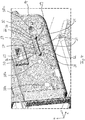
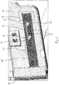
Fig. 3 und4 ist ein Teilausschnitt des Innenbehälters 19 dargestellt. Zu erkennen ist die einstückig mit dem Innenbehälter 19 und somit auch dem Wandelement 14 ausgebildete Justagekontur 21. Die Justagekontur 21 wird durch einen Vorsprung 22 bei der Herstellung des Innenbehälters 19 durch Thermoformen gebildet. Dementsprechend weist die Justagekontur 21 im Wesentlichen eine sich über den gesamten Vorsprung 22 erstreckende konstante Wandstärke auf. Die Wandstärke entspricht im Wesentlichen der Wandstärke des Wandelements 14 außerhalb der Justagekontur 21. Der Vorsprung 22 erstreckt sich in Breitenrichtung X von dem Aufnahmeraum 9 weg. Insbesondere ist der Vorsprung 22 auf der dem Aufnahmeraum 9 abgewandten Seite 14b des Wandelements 14 ausgebildet. Eine dem Vorsprung 22 in seiner Form und Größe komplementär ausgebildete Vertiefung 23 ist auf der dem Aufnahmeraum 9 zugewandten Innenseite 14a des Wandelements 14 ausgebildet. - Der Vorsprung 22 ist länglich ausgebildet. Insbesondere ist eine Längserstreckung 24 größer als eine Breitenerstreckung 25 und größer als eine Höhenerstreckung 26. Der Vorsprung 22 ist derart positioniert, dass sich seine Längserstreckung 24 parallel zur Tiefenrichtung Y erstreckt.
- Der Vorsprung 22 weist einen rippenförmigen Abschnitt 27 auf, welcher eine Längserstreckung 28 aufweist die ca. 75% der Längserstreckung 24 des gesamten Vorsprung 22 beträgt. An Endabschnitten 29 des rippenförmigen Abschnitts 27 sind Vergrößerungsabschnitte 30 angeformt. Die Vergrößerungsabschnitte 30 erstrecken sich sowohl in Breitenrichtung X als auch in Höhenrichtung Z über den rippenförmigen Abschnitt 27 hinaus. Entsprechend sind jene durch die Vergrößerungsabschnitte 30 gebildeten Abschnitte der Vertiefung 23 tiefer und breiter als jener durch den rippenförmigen Abschnitt 27 gebildete Abschnitt der Vertiefung 23. Insbesondere weisen beide Vergrößerungsabschnitte 30 eine größere Höhenerstreckung (diese entspricht der Höhenerstreckung 26 des gesamten Vorsprung) auf, als die Höhenerstreckung 32 des rippenförmigen Abschnitts 27.
- Die Justagekontur 21 weist zwei innerhalb der Vertiefung 23 ausgebildete Durchbrüche 31 auf. Die Durchbrüche 31 sind beide vollständig innerhalb des rippenförmigen Abschnitts 27 angeordnet.
- Die Vertiefung 23 weist Auflageflächen 33,34 auf. Die Auflageflächen 33 sind durch Begrenzungswände jenes Abschnitts der Vertiefung 23 gebildet, der durch die komplementäre Form des Vergrößerungsabschnitts 30 gebildet ist. Die Auflagefläche 34 ist durch eine seitliche Begrenzungswand 35 jenes Abschnitts der Vertiefung 33 gebildet, der durch den rippenförmigen Abschnitt 27 gebildet ist. Die seitliche Begrenzungswand 35 und damit die Auflagefläche 34 ist im Wesentlichen horizontal ausgebildet. Die Größe der Auflagefläche 34 ist größer als die Summe der Flächen der Auflageflächen 33. Der Vorsprung 22 weist Auflageflächen 36,37 auf.
- Das Wandelement 14 weist weiterhin drei Durchbrüche 38a,38b,38c auf. Die Justagekontur 21 ist in Tiefenrichtung Y zwischen zwei benachbarten Durchbrüchen 38b,38c angeordnet. Insbesondere ist die Justagekontur 21 überlappungsfrei mit den Durchbrüchen 38a,38b,38c ausgebildet. In Höhenrichtung Z sind die Durchbrüche 38a,38b,38c und die Justagekontur 21 im Wesentlichen auf einer Höhenebene angeordnet.
- Die Durchbrüche 38a,38b,38c sind ebenfalls in dem Wandelement 14, also in der Seitenwand, angeordnet. Das Wandelement 14 geht einstückig in ein weiteres Wandelement 39 über, welches den Boden des Aufnahmeraums 9 bildet.
-
Fig. 5 zeigt das an dem Wandelement 14 angeordnete Halteteil 40. Das einstückige und aus Metall bestehende Halteteil 40 weist einen bezüglich seiner Längserstreckung 41 außer mittig angeordneten Koppelbereich 42 auf. Der Koppelabschnitt 42 erstreckt sich nur über einen Teilabschnitt 65 der Längserstreckung 42. - Der Koppelabschnitt 42 umfasst ein Brückenelement 43 sowie zwei an seinen Endabschnitten 44 angeordnete Durchbrüche 45. An dem Brückenelement 43 ist eine Abstützfläche 46 ausgebildet, welche im montierten Zustand des Halteteils 40 die Auflagefläche 37 kontaktiert, um auf das Halteteil 40 einwirkende Gewichtskräfte zu übertragen. Das Rückenelement 43 umfasst weiterhin Schraublöcher 47, welche in einem Zylinderabsatz 48 ausgebildet sind.
- Das Halteteil 40 umfasst darüber hinaus drei Befestigungsabschnitte 49, welche im wesentlichen durch Vorsprünge 50 gebildet sind. Die Vorsprünge 50 erstrecken sich entgegen der Breitenrichtung X, das heißt in Richtung des Aufnahmeraums 9 (siehe auch
Figur 7 ). Die Vorsprünge 50 sind rotationssymmetrisch ausgebildet und weisen jeweils ein mittig angeordnetes Schraubloch 51 auf, welches in einem Zylinderabsatz 52 ausgebildet ist. - Das Halteteil 40 weist weiterhin zwei Rippen 53 auf die über die komplette Längserstreckung 41 ausgebildet sind und in Breitenrichtung X von einer Basisplatte 54 abstehen.
-
Fig. 6 zeigt das an dem Innenbehälter 19, insbesondere an dem Wandelement 14 montierte Halteteil 40. Wie zu erkennen ist, greift das Brückenelement 43 formschlüssig über den rippenförmigen Abschnitt 27. Die Durchbrüche 45 fassen die Vergrößerungsabschnitt 30 ein. - Schematisch dargestellt sind weiterhin Klebemittel 55,56. Bei dem (teilweise dargestellten) Klebemittel 55 handelt es sich um Heißkleber welcher über die kompletten Randabschnitte des Halteteils 40 appliziert werden kann. Bei dem (teilweise dargestellten) Klebemittel 56 handelt es sich um Klebeband, welches über die gesamte, dem Wandelement 14 abgewandte Oberfläche des Halteteils 40 appliziert werden kann.
- Wie in
Fig. 7 zu erkennen ist, greifen die Befestigungsabschnitte 49 in die Durchbrüche 38a,38b,38c ein. Oberflächen 57 der Befestigungsabschnitte 49 ragen dabei nicht in den Aufnahmeraum 9 hinein. Vielmehr sind die Oberflächen 57 im Wesentlichen bündig mit einer die Durchbrüche 38a,38b,38c einfassenden Oberfläche des Wandelements 14. - In der Vertiefung 23 ist ein Fixierelement 58 (siehe auch
Fig. 8 ) angeordnet. Das Fixierelement 58 ist mittels zweier Schrauben 59, welche die Durchbrüche 31 durchdringen, mit dem Halteteil 40 verbunden. Hierfür weist das Fixierungselement 58 zwei Durchführungen 60 auf. - Eine Oberfläche 61 des einstückigen und als Kunststoff-Spritzgussteil gefertigten Fixierelements 58 ragt dabei nicht in den Aufnahmeraum 9 hinein. Diese Oberfläche 61 ist vielmehr in Breitenrichtung X bezüglich des Aufnahmeraums 9 zurückversetzt.
- Das Fixierelement 58 umfasst ein rippenförmiges Mittelstück 62 sowie zwei an dessen Endabschnitten 63 angeformte, topfförmige Verbreiterungsstücke 64. Im montierten Zustand füllt das Fixierelement 58 die Vertiefung 23 im Wesentlichen vollständig aus. An dem Mittelstück 62 ist eine Abstützfläche 66 ausgebildet, mit welcher sich das Fixierelement 58 auf der Auflagefläche 34 abstützen kann.
-
- 1
- Haushaltsgerät
- 2
- Korpus
- 3
- Aufnahmeraum
- 4
- Frischhaltefach
- 5
- Tür
- 6
- Tür
- 7
- Tür
- 8
- Aufnahmeraum
- 9
- Aufnahmeraum
- 10
- Tür
- 11
- Tür
- 12
- Schublade
- 13
- Wandelement
- 13a
- Innenseite
- 13b
- Außenseite
- 14
- Wandelement
- 14a
- Innenseite
- 15
- Auszugsvorrichtung
- 16
- Behälter
- 17
- Halteteil
- 18
- Außenwandung
- 19
- Innenbehälter
- 20
- Einbauteil
- 21
- Justagekontur
- 22
- Vorsprung
- 23
- Vertiefung
- 24
- Längenerstreckung
- 25
- Breitenerstreckung
- 26
- Höhenerstreckung
- 27
- rippenförmiger Abschnitt
- 28
- Längserstreckung
- 29
- Endabschnitt
- 30
- Vergrößerungsabschnitt
- 31
- Durchbruch
- 32
- Höhenerstreckung
- 33
- Auflagefläche
- 34
- Auflagefläche
- 35
- Begrenzungswand
- 36
- Auflagefläche
- 37
- Auflagefläche
- 38a
- Durchbruch
- 38b
- Durchbruch
- 38c
- Durchbruch
- 39
- Wandelement
- 40
- Halteteil
- 41
- Längserstreckung
- 42
- Koppelabschnitt
- 43
- Brückenelement
- 44
- Endabschnitt
- 45
- Durchbruch
- 46
- Abstützfläche
- 47
- Schraubloch
- 48
- Zylinderansatz
- 49
- Befestigungsabschnitt
- 50
- Vorsprung
- 51
- Schraubloch
- 52
- Zylinderabsatz
- 53
- Rippe
- 54
- Basisplatte
- 55
- Klebemittel
- 56
- Klebemittel
- 57
- Oberfläche
- 58
- Fixierelement
- 59
- Schraube
- 60
- Durchführung
- 61
- Oberfläche
- 62
- Mittelstück
- 63
- Endabschnitt
- 64
- Verbreiterungsstück
- 65
- Teilabschnitt
- 66
- Abstützfläche
Claims (15)
- Haushaltsgerät (1) mit einem Korpus (2) sowie einem sich in dem Korpus (2) befindlichen und durch ein Wandelement (13,14) zumindest abschnittsweise begrenzten Aufnahmeraum (9) und mit einem Halteteil (17,40), welches auf einer dem Aufnahmeraum (9) abgewandten Seite (13b,14b) des Wandelements (13,14) angeordnet ist und welches mit einer an dem Wandelement (14) ausgebildeten Justagekontur (21) gekoppelt ist und sich in einer das Wandelement (14) umfassenden Ebene über die Justagekontur (21) erstreckt, dadurch gekennzeichnet, dass die Justagekontur (21) einen dem Aufnahmeraum (9) abgewandten und in der das Wandelement (14) umfassenden Ebene länglich ausgebildeten Vorsprung (22) aufweist.
- Haushaltsgerät nach Anspruch 1, dadurch gekennzeichnet, dass eine Längserstreckung (24) des Vorsprungs (21) horizontal angeordnet ist.
- Haushaltsgerät nach Anspruch 1, dadurch gekennzeichnet, dass die Justagekontur (21) einen rippenförmigen Abschnitt (27) aufweist.
- Haushaltsgerät nach Anspruch 3, dadurch gekennzeichnet, dass an Endabschnitten (29) des rippenförmigen Abschnitts (27) Vergrößerungsabschnitte (30) angeformt sind.
- Haushaltsgerät nach Anspruch 4, dadurch gekennzeichnet, dass eine ausgehend von einer dem Aufnahmeraum (9) abgewandten Oberfläche (14a) des Wandelements (14) gemessene Höhe (26) des Vergrößerungsabschnitts (30) größer ist, als eine entsprechend gemessene Höhe (32) des rippenförmigen Abschnitts (27) und/oder dass eine senkrecht zur Längserstreckung (24) der Justagekontur (21) gemessene Breite (25) des Vergrößerungsabschnitts (30) größer ist, als eine entsprechend gemessene Breite des rippenförmigen Abschnitts (27).
- Haushaltsgerät nach einem der vorhergehenden Ansprüche, dadurch gekennzeichnet, dass das Halteteil (40) einen Koppelabschnitt (42) aufweist, mittels welchem das Halteteil (40) formschlüssig und/oder kraftschlüssig mit der Justagekontur (21) gekoppelt ist.
- Haushaltsgerät nach Anspruch 6, dadurch gekennzeichnet, dass der Koppelabschnitt (42) zumindest ein Brückenelement (43) und/oder zumindest einen Durchbruch (45) aufweist.
- Haushaltsgerät nach einem der vorhergehenden Ansprüche, dadurch gekennzeichnet, dass das Halteteil (40) länglich ausgebildet ist und sich der Koppelabschnitt (42) nur über einen Teilabschnitt (65) einer Längenerstreckung (41) des Halteteils (40) erstreckt.
- Haushaltsgerät nach einem der vorhergehenden Ansprüche, dadurch gekennzeichnet, dass das Halteteil (40) länglich ausgebildet ist und wenigstens zwei entlang seiner Längserstreckung (41) voneinander beabstandete Befestigungsabschnitte (49) aufweist, an denen ein in dem Aufnahmeraum angeordnetes Einbauteil (20) befestigt ist.
- Haushaltsgerät nach zumindest Anspruch 6 und 9, dadurch gekennzeichnet, dass der Koppelabschnitt (42) bezüglich der Längserstreckung (41) des Halteteils (40) zwischen den wenigstens zwei Befestigungsabschnitten (49) angeordnet ist.
- Haushaltsgerät nach Anspruch 9 oder 10, dadurch gekennzeichnet, dass das Wandelement (14) mindestens zwei Durchbrüche (38a,38b,38c) aufweist und jeder Befestigungsabschnitt (49) durch einen Durchbruch (38a,38b,38c) zugänglich ist.
- Haushaltsgerät nach einem der vorhergehenden Ansprüche, dadurch gekennzeichnet, dass das Halteteil (40) länglich ausgebildet und waagrecht angeordnet ist und dass das ein in dem Aufnahmeraum (9) angeordnetes und an dem Halteteil (40) befestigtes Einbauteil (20) Bestandteil einer Auszugsvorrichtung (15) ist.
- Haushaltsgerät nach einem der vorhergehenden Ansprüche, dadurch gekennzeichnet, dass die Justagekontur (21) eine dem Aufnahmeraum (9) zugewandte Vertiefung (23) aufweist, in der sich ein Fixierelement (58) befindet, welches mit dem Halteteil (40) gekoppelt, insbesondere verschraubt, ist.
- Haushaltsgerät nach einem der vorhergehenden Ansprüche, dadurch gekennzeichnet, dass das Halteteil (40) und das Wandelement (14), vorzugsweise im Bereich der Justagekontur (21), miteinander verschraubt sind.
- Haushaltsgerät nach einem der vorhergehenden Ansprüche, gekennzeichnet durch ein Klebemittel (55,56) welches das Halteteil (40) und das Wandelement (14) kontaktiert.
Applications Claiming Priority (1)
| Application Number | Priority Date | Filing Date | Title |
|---|---|---|---|
| DE102018204780.4A DE102018204780A1 (de) | 2018-03-28 | 2018-03-28 | Haushaltsgerät mit einer an einem Wandelement ausgebildeten Justagekontur |
Publications (2)
| Publication Number | Publication Date |
|---|---|
| EP3546860A1 true EP3546860A1 (de) | 2019-10-02 |
| EP3546860B1 EP3546860B1 (de) | 2022-11-16 |
Family
ID=65812066
Family Applications (1)
| Application Number | Title | Priority Date | Filing Date |
|---|---|---|---|
| EP19162593.8A Active EP3546860B1 (de) | 2018-03-28 | 2019-03-13 | Haushaltsgerät mit einer an einem wandelement ausgebildeten justagekontur |
Country Status (3)
| Country | Link |
|---|---|
| US (1) | US10823493B2 (de) |
| EP (1) | EP3546860B1 (de) |
| DE (1) | DE102018204780A1 (de) |
Families Citing this family (1)
| Publication number | Priority date | Publication date | Assignee | Title |
|---|---|---|---|---|
| US12495950B2 (en) | 2023-07-13 | 2025-12-16 | Haier Us Appliance Solutions, Inc. | Universal inner member for a slide assembly of a dishwasher appliance |
Citations (4)
| Publication number | Priority date | Publication date | Assignee | Title |
|---|---|---|---|---|
| US20080115526A1 (en) * | 2006-11-20 | 2008-05-22 | Samsung Electronics Co., Ltd. | Refrigerator |
| KR20100080971A (ko) * | 2009-01-05 | 2010-07-14 | 엘지전자 주식회사 | 냉장고 |
| WO2011080654A2 (zh) | 2009-12-29 | 2011-07-07 | Bsh博世和西门子家用器具有限公司 | 冰箱 |
| KR20140144445A (ko) * | 2013-06-11 | 2014-12-19 | 주식회사 대유위니아 | 냉장고용 그로메트 |
Family Cites Families (7)
| Publication number | Priority date | Publication date | Assignee | Title |
|---|---|---|---|---|
| IL139957A0 (en) * | 2000-11-28 | 2002-02-10 | Iscar Ltd | Cutting tool |
| US6834692B2 (en) * | 2002-08-07 | 2004-12-28 | Lindsay Forest Products, Inc. | Log debarking tip |
| KR100577422B1 (ko) * | 2003-12-11 | 2006-05-08 | 삼성전자주식회사 | 저장고 |
| US7380410B2 (en) * | 2005-03-31 | 2008-06-03 | U-Line Corporation | Pull-out access cooler unit |
| DE102005021591A1 (de) * | 2005-05-10 | 2006-11-16 | BSH Bosch und Siemens Hausgeräte GmbH | Haushaltsgerät mit Teleskopauszug |
| EP1775536A3 (de) * | 2005-10-17 | 2013-01-23 | Samsung Electronics Co., Ltd. | Kühlschrank |
| KR101644014B1 (ko) * | 2008-10-13 | 2016-07-29 | 삼성전자주식회사 | 냉장고 |
-
2018
- 2018-03-28 DE DE102018204780.4A patent/DE102018204780A1/de active Pending
-
2019
- 2019-03-11 US US16/298,254 patent/US10823493B2/en not_active Expired - Fee Related
- 2019-03-13 EP EP19162593.8A patent/EP3546860B1/de active Active
Patent Citations (4)
| Publication number | Priority date | Publication date | Assignee | Title |
|---|---|---|---|---|
| US20080115526A1 (en) * | 2006-11-20 | 2008-05-22 | Samsung Electronics Co., Ltd. | Refrigerator |
| KR20100080971A (ko) * | 2009-01-05 | 2010-07-14 | 엘지전자 주식회사 | 냉장고 |
| WO2011080654A2 (zh) | 2009-12-29 | 2011-07-07 | Bsh博世和西门子家用器具有限公司 | 冰箱 |
| KR20140144445A (ko) * | 2013-06-11 | 2014-12-19 | 주식회사 대유위니아 | 냉장고용 그로메트 |
Also Published As
| Publication number | Publication date |
|---|---|
| EP3546860B1 (de) | 2022-11-16 |
| US10823493B2 (en) | 2020-11-03 |
| US20190301790A1 (en) | 2019-10-03 |
| DE102018204780A1 (de) | 2019-10-02 |
Similar Documents
| Publication | Publication Date | Title |
|---|---|---|
| DE102009046612A1 (de) | Kältegerät mit einem Türabsteller und einer schwimmend gelagerten Rastvorrichtung | |
| DE102019218224A1 (de) | Haushaltskühlgerät mit einem Anschlussstift oder einem Arretierelement in einer Wandeinheit eines Gehäuses eines Eisbereiters sowie Verfahren zur Montage eines Gehäuses eines Eisbereiters | |
| EP1397628A1 (de) | Kühlgutbehälter für ein kältegerät | |
| DE102019205875A1 (de) | Haushaltskältegerät und Verfahren zum Herstellen eines Haushaltskältegerätes | |
| EP3441704A1 (de) | Tür für ein Haushaltskältegerät mit spezifisch Befestiger Abdeckplatte sowie Haushaltskältegerät | |
| DE102017205089A1 (de) | Haushaltskältegerät mit einer Innenverkleidung mit mehreren separaten Verkleidungswänden sowie Verfahren zum Herstellen eines Haushaltskältegeräts | |
| EP3775727B1 (de) | Haushaltsgerät mit einer wand, die ein integriertes, erhabenes koppelelement zum koppeln mit einem daran angeordneten hinterlegteil aufweist, sowie verfahren zur montage des koppelelements an der wand | |
| WO2014095632A1 (de) | Wandungsanordnung für ein haushaltskältegerät sowie haushaltskältegerät | |
| EP3546860B1 (de) | Haushaltsgerät mit einer an einem wandelement ausgebildeten justagekontur | |
| DE102009002802A1 (de) | Kältegerät mit einer Kühlgutablage | |
| EP2492620B1 (de) | Kältegerät mit einem Verdichterkondensator | |
| EP2756245B1 (de) | Kältegerät, insbesondere haushaltskältegerät | |
| EP2697582A2 (de) | Einbau-kältegerät mit einem beschlagsbauteil | |
| DE102009046613A1 (de) | Kältegerät mit einem Türabsteller und einer Rastvorrichtung | |
| DE102018104398A1 (de) | Möbel oder Haushaltsgerät und Verfahren zur Montage einer Funktionseinheit eines Schubelements in einem Möbel oder Haushaltsgerät | |
| EP2420783A2 (de) | Kältegerät mit Rastmitteln für einen Fachboden | |
| EP2270407B1 (de) | Haushaltsgerät, insbesondere Kühl-und/oder Gefriergerät | |
| DE102017204821A1 (de) | Haushaltsgerätevorrichtung mit einem Korpus, einem Verschlusselement sowie einer an dem Korpus und an dem Verschlusselement befestigten Leitung | |
| DE102019218222A1 (de) | Haushaltskühlgerät mit einem Vorsprung als Kondenswasser-Tropfleiste in einer Wand eines Eisbereiters | |
| WO2017036779A1 (de) | Haushaltsgerätetür und haushaltsgerät mit einer haushaltsgerätetür | |
| EP2980513B1 (de) | Kühlgutablage für ein kältegerät | |
| EP2281159A1 (de) | Tür für ein haushaltsgerät | |
| DE102015208832A1 (de) | Haushaltskältegerät mit integrierter Platten-Auflage und/oder integrierter Behälter-Auflage in einer Seitenwand eines Innenbehälters sowie Verfahren zum Herstellen und Bestücken eines Haushaltskältegeräts | |
| DE102008018233A1 (de) | Kältegerät mit Türabsteller | |
| EP2561291A2 (de) | Türblatt, verfahren zum herstellen eines türblatts und kältegerät mit einem türblatt |
Legal Events
| Date | Code | Title | Description |
|---|---|---|---|
| PUAI | Public reference made under article 153(3) epc to a published international application that has entered the european phase |
Free format text: ORIGINAL CODE: 0009012 |
|
| STAA | Information on the status of an ep patent application or granted ep patent |
Free format text: STATUS: THE APPLICATION HAS BEEN PUBLISHED |
|
| AK | Designated contracting states |
Kind code of ref document: A1 Designated state(s): AL AT BE BG CH CY CZ DE DK EE ES FI FR GB GR HR HU IE IS IT LI LT LU LV MC MK MT NL NO PL PT RO RS SE SI SK SM TR |
|
| AX | Request for extension of the european patent |
Extension state: BA ME |
|
| STAA | Information on the status of an ep patent application or granted ep patent |
Free format text: STATUS: REQUEST FOR EXAMINATION WAS MADE |
|
| 17P | Request for examination filed |
Effective date: 20200402 |
|
| RBV | Designated contracting states (corrected) |
Designated state(s): AL AT BE BG CH CY CZ DE DK EE ES FI FR GB GR HR HU IE IS IT LI LT LU LV MC MK MT NL NO PL PT RO RS SE SI SK SM TR |
|
| GRAP | Despatch of communication of intention to grant a patent |
Free format text: ORIGINAL CODE: EPIDOSNIGR1 |
|
| STAA | Information on the status of an ep patent application or granted ep patent |
Free format text: STATUS: GRANT OF PATENT IS INTENDED |
|
| RIC1 | Information provided on ipc code assigned before grant |
Ipc: F25D 25/02 20060101ALI20220617BHEP Ipc: F25D 23/06 20060101AFI20220617BHEP |
|
| INTG | Intention to grant announced |
Effective date: 20220718 |
|
| GRAS | Grant fee paid |
Free format text: ORIGINAL CODE: EPIDOSNIGR3 |
|
| GRAA | (expected) grant |
Free format text: ORIGINAL CODE: 0009210 |
|
| STAA | Information on the status of an ep patent application or granted ep patent |
Free format text: STATUS: THE PATENT HAS BEEN GRANTED |
|
| AK | Designated contracting states |
Kind code of ref document: B1 Designated state(s): AL AT BE BG CH CY CZ DE DK EE ES FI FR GB GR HR HU IE IS IT LI LT LU LV MC MK MT NL NO PL PT RO RS SE SI SK SM TR |
|
| REG | Reference to a national code |
Ref country code: GB Ref legal event code: FG4D Free format text: NOT ENGLISH |
|
| REG | Reference to a national code |
Ref country code: CH Ref legal event code: EP |
|
| REG | Reference to a national code |
Ref country code: IE Ref legal event code: FG4D Free format text: LANGUAGE OF EP DOCUMENT: GERMAN |
|
| REG | Reference to a national code |
Ref country code: DE Ref legal event code: R096 Ref document number: 502019006258 Country of ref document: DE |
|
| REG | Reference to a national code |
Ref country code: AT Ref legal event code: REF Ref document number: 1531985 Country of ref document: AT Kind code of ref document: T Effective date: 20221215 |
|
| REG | Reference to a national code |
Ref country code: LT Ref legal event code: MG9D |
|
| REG | Reference to a national code |
Ref country code: NL Ref legal event code: MP Effective date: 20221116 |
|
| PG25 | Lapsed in a contracting state [announced via postgrant information from national office to epo] |
Ref country code: SE Free format text: LAPSE BECAUSE OF FAILURE TO SUBMIT A TRANSLATION OF THE DESCRIPTION OR TO PAY THE FEE WITHIN THE PRESCRIBED TIME-LIMIT Effective date: 20221116 Ref country code: PT Free format text: LAPSE BECAUSE OF FAILURE TO SUBMIT A TRANSLATION OF THE DESCRIPTION OR TO PAY THE FEE WITHIN THE PRESCRIBED TIME-LIMIT Effective date: 20230316 Ref country code: NO Free format text: LAPSE BECAUSE OF FAILURE TO SUBMIT A TRANSLATION OF THE DESCRIPTION OR TO PAY THE FEE WITHIN THE PRESCRIBED TIME-LIMIT Effective date: 20230216 Ref country code: LT Free format text: LAPSE BECAUSE OF FAILURE TO SUBMIT A TRANSLATION OF THE DESCRIPTION OR TO PAY THE FEE WITHIN THE PRESCRIBED TIME-LIMIT Effective date: 20221116 Ref country code: FI Free format text: LAPSE BECAUSE OF FAILURE TO SUBMIT A TRANSLATION OF THE DESCRIPTION OR TO PAY THE FEE WITHIN THE PRESCRIBED TIME-LIMIT Effective date: 20221116 Ref country code: ES Free format text: LAPSE BECAUSE OF FAILURE TO SUBMIT A TRANSLATION OF THE DESCRIPTION OR TO PAY THE FEE WITHIN THE PRESCRIBED TIME-LIMIT Effective date: 20221116 |
|
| PG25 | Lapsed in a contracting state [announced via postgrant information from national office to epo] |
Ref country code: RS Free format text: LAPSE BECAUSE OF FAILURE TO SUBMIT A TRANSLATION OF THE DESCRIPTION OR TO PAY THE FEE WITHIN THE PRESCRIBED TIME-LIMIT Effective date: 20221116 Ref country code: PL Free format text: LAPSE BECAUSE OF FAILURE TO SUBMIT A TRANSLATION OF THE DESCRIPTION OR TO PAY THE FEE WITHIN THE PRESCRIBED TIME-LIMIT Effective date: 20221116 Ref country code: LV Free format text: LAPSE BECAUSE OF FAILURE TO SUBMIT A TRANSLATION OF THE DESCRIPTION OR TO PAY THE FEE WITHIN THE PRESCRIBED TIME-LIMIT Effective date: 20221116 Ref country code: IS Free format text: LAPSE BECAUSE OF FAILURE TO SUBMIT A TRANSLATION OF THE DESCRIPTION OR TO PAY THE FEE WITHIN THE PRESCRIBED TIME-LIMIT Effective date: 20230316 Ref country code: HR Free format text: LAPSE BECAUSE OF FAILURE TO SUBMIT A TRANSLATION OF THE DESCRIPTION OR TO PAY THE FEE WITHIN THE PRESCRIBED TIME-LIMIT Effective date: 20221116 Ref country code: GR Free format text: LAPSE BECAUSE OF FAILURE TO SUBMIT A TRANSLATION OF THE DESCRIPTION OR TO PAY THE FEE WITHIN THE PRESCRIBED TIME-LIMIT Effective date: 20230217 |
|
| PGFP | Annual fee paid to national office [announced via postgrant information from national office to epo] |
Ref country code: DE Payment date: 20230331 Year of fee payment: 5 |
|
| PG25 | Lapsed in a contracting state [announced via postgrant information from national office to epo] |
Ref country code: NL Free format text: LAPSE BECAUSE OF FAILURE TO SUBMIT A TRANSLATION OF THE DESCRIPTION OR TO PAY THE FEE WITHIN THE PRESCRIBED TIME-LIMIT Effective date: 20221116 |
|
| PG25 | Lapsed in a contracting state [announced via postgrant information from national office to epo] |
Ref country code: SM Free format text: LAPSE BECAUSE OF FAILURE TO SUBMIT A TRANSLATION OF THE DESCRIPTION OR TO PAY THE FEE WITHIN THE PRESCRIBED TIME-LIMIT Effective date: 20221116 Ref country code: RO Free format text: LAPSE BECAUSE OF FAILURE TO SUBMIT A TRANSLATION OF THE DESCRIPTION OR TO PAY THE FEE WITHIN THE PRESCRIBED TIME-LIMIT Effective date: 20221116 Ref country code: EE Free format text: LAPSE BECAUSE OF FAILURE TO SUBMIT A TRANSLATION OF THE DESCRIPTION OR TO PAY THE FEE WITHIN THE PRESCRIBED TIME-LIMIT Effective date: 20221116 Ref country code: DK Free format text: LAPSE BECAUSE OF FAILURE TO SUBMIT A TRANSLATION OF THE DESCRIPTION OR TO PAY THE FEE WITHIN THE PRESCRIBED TIME-LIMIT Effective date: 20221116 Ref country code: CZ Free format text: LAPSE BECAUSE OF FAILURE TO SUBMIT A TRANSLATION OF THE DESCRIPTION OR TO PAY THE FEE WITHIN THE PRESCRIBED TIME-LIMIT Effective date: 20221116 |
|
| REG | Reference to a national code |
Ref country code: DE Ref legal event code: R097 Ref document number: 502019006258 Country of ref document: DE |
|
| PG25 | Lapsed in a contracting state [announced via postgrant information from national office to epo] |
Ref country code: SK Free format text: LAPSE BECAUSE OF FAILURE TO SUBMIT A TRANSLATION OF THE DESCRIPTION OR TO PAY THE FEE WITHIN THE PRESCRIBED TIME-LIMIT Effective date: 20221116 Ref country code: AL Free format text: LAPSE BECAUSE OF FAILURE TO SUBMIT A TRANSLATION OF THE DESCRIPTION OR TO PAY THE FEE WITHIN THE PRESCRIBED TIME-LIMIT Effective date: 20221116 |
|
| PLBE | No opposition filed within time limit |
Free format text: ORIGINAL CODE: 0009261 |
|
| STAA | Information on the status of an ep patent application or granted ep patent |
Free format text: STATUS: NO OPPOSITION FILED WITHIN TIME LIMIT |
|
| 26N | No opposition filed |
Effective date: 20230817 |
|
| PG25 | Lapsed in a contracting state [announced via postgrant information from national office to epo] |
Ref country code: MC Free format text: LAPSE BECAUSE OF FAILURE TO SUBMIT A TRANSLATION OF THE DESCRIPTION OR TO PAY THE FEE WITHIN THE PRESCRIBED TIME-LIMIT Effective date: 20221116 |
|
| REG | Reference to a national code |
Ref country code: CH Ref legal event code: PL |
|
| GBPC | Gb: european patent ceased through non-payment of renewal fee |
Effective date: 20230313 |
|
| PG25 | Lapsed in a contracting state [announced via postgrant information from national office to epo] |
Ref country code: SI Free format text: LAPSE BECAUSE OF FAILURE TO SUBMIT A TRANSLATION OF THE DESCRIPTION OR TO PAY THE FEE WITHIN THE PRESCRIBED TIME-LIMIT Effective date: 20221116 |
|
| REG | Reference to a national code |
Ref country code: BE Ref legal event code: MM Effective date: 20230331 |
|
| PG25 | Lapsed in a contracting state [announced via postgrant information from national office to epo] |
Ref country code: LU Free format text: LAPSE BECAUSE OF NON-PAYMENT OF DUE FEES Effective date: 20230313 |
|
| REG | Reference to a national code |
Ref country code: IE Ref legal event code: MM4A |
|
| PG25 | Lapsed in a contracting state [announced via postgrant information from national office to epo] |
Ref country code: GB Free format text: LAPSE BECAUSE OF NON-PAYMENT OF DUE FEES Effective date: 20230313 |
|
| PG25 | Lapsed in a contracting state [announced via postgrant information from national office to epo] |
Ref country code: LI Free format text: LAPSE BECAUSE OF NON-PAYMENT OF DUE FEES Effective date: 20230331 Ref country code: IE Free format text: LAPSE BECAUSE OF NON-PAYMENT OF DUE FEES Effective date: 20230313 Ref country code: GB Free format text: LAPSE BECAUSE OF NON-PAYMENT OF DUE FEES Effective date: 20230313 Ref country code: FR Free format text: LAPSE BECAUSE OF NON-PAYMENT OF DUE FEES Effective date: 20230331 Ref country code: CH Free format text: LAPSE BECAUSE OF NON-PAYMENT OF DUE FEES Effective date: 20230331 |
|
| PG25 | Lapsed in a contracting state [announced via postgrant information from national office to epo] |
Ref country code: BE Free format text: LAPSE BECAUSE OF NON-PAYMENT OF DUE FEES Effective date: 20230331 |
|
| PG25 | Lapsed in a contracting state [announced via postgrant information from national office to epo] |
Ref country code: IT Free format text: LAPSE BECAUSE OF FAILURE TO SUBMIT A TRANSLATION OF THE DESCRIPTION OR TO PAY THE FEE WITHIN THE PRESCRIBED TIME-LIMIT Effective date: 20221116 |
|
| REG | Reference to a national code |
Ref country code: DE Ref legal event code: R119 Ref document number: 502019006258 Country of ref document: DE |
|
| PG25 | Lapsed in a contracting state [announced via postgrant information from national office to epo] |
Ref country code: BG Free format text: LAPSE BECAUSE OF FAILURE TO SUBMIT A TRANSLATION OF THE DESCRIPTION OR TO PAY THE FEE WITHIN THE PRESCRIBED TIME-LIMIT Effective date: 20221116 |
|
| PG25 | Lapsed in a contracting state [announced via postgrant information from national office to epo] |
Ref country code: BG Free format text: LAPSE BECAUSE OF FAILURE TO SUBMIT A TRANSLATION OF THE DESCRIPTION OR TO PAY THE FEE WITHIN THE PRESCRIBED TIME-LIMIT Effective date: 20221116 |
|
| PG25 | Lapsed in a contracting state [announced via postgrant information from national office to epo] |
Ref country code: DE Free format text: LAPSE BECAUSE OF NON-PAYMENT OF DUE FEES Effective date: 20241001 |
|
| PG25 | Lapsed in a contracting state [announced via postgrant information from national office to epo] |
Ref country code: DE Free format text: LAPSE BECAUSE OF NON-PAYMENT OF DUE FEES Effective date: 20241001 |
|
| REG | Reference to a national code |
Ref country code: AT Ref legal event code: MM01 Ref document number: 1531985 Country of ref document: AT Kind code of ref document: T Effective date: 20240313 |
|
| PG25 | Lapsed in a contracting state [announced via postgrant information from national office to epo] |
Ref country code: AT Free format text: LAPSE BECAUSE OF NON-PAYMENT OF DUE FEES Effective date: 20240313 |
|
| PG25 | Lapsed in a contracting state [announced via postgrant information from national office to epo] |
Ref country code: CY Free format text: LAPSE BECAUSE OF FAILURE TO SUBMIT A TRANSLATION OF THE DESCRIPTION OR TO PAY THE FEE WITHIN THE PRESCRIBED TIME-LIMIT; INVALID AB INITIO Effective date: 20190313 |
|
| PG25 | Lapsed in a contracting state [announced via postgrant information from national office to epo] |
Ref country code: HU Free format text: LAPSE BECAUSE OF FAILURE TO SUBMIT A TRANSLATION OF THE DESCRIPTION OR TO PAY THE FEE WITHIN THE PRESCRIBED TIME-LIMIT; INVALID AB INITIO Effective date: 20190313 |
|
| PG25 | Lapsed in a contracting state [announced via postgrant information from national office to epo] |
Ref country code: TR Free format text: LAPSE BECAUSE OF FAILURE TO SUBMIT A TRANSLATION OF THE DESCRIPTION OR TO PAY THE FEE WITHIN THE PRESCRIBED TIME-LIMIT Effective date: 20221116 |
|
| PGFP | Annual fee paid to national office [announced via postgrant information from national office to epo] |
Ref country code: AT Payment date: 20260410 Year of fee payment: 5 |