EP3546728A1 - Steuerungsvorrichtung für einen motor - Google Patents
Steuerungsvorrichtung für einen motor Download PDFInfo
- Publication number
- EP3546728A1 EP3546728A1 EP19163823.8A EP19163823A EP3546728A1 EP 3546728 A1 EP3546728 A1 EP 3546728A1 EP 19163823 A EP19163823 A EP 19163823A EP 3546728 A1 EP3546728 A1 EP 3546728A1
- Authority
- EP
- European Patent Office
- Prior art keywords
- calculating
- timing
- intake
- amount
- exhaust
- Prior art date
- Legal status (The legal status is an assumption and is not a legal conclusion. Google has not performed a legal analysis and makes no representation as to the accuracy of the status listed.)
- Withdrawn
Links
Images


Classifications
-
- F—MECHANICAL ENGINEERING; LIGHTING; HEATING; WEAPONS; BLASTING
- F02—COMBUSTION ENGINES; HOT-GAS OR COMBUSTION-PRODUCT ENGINE PLANTS
- F02D—CONTROLLING COMBUSTION ENGINES
- F02D13/00—Controlling the engine output power by varying inlet or exhaust valve operating characteristics, e.g. timing
- F02D13/02—Controlling the engine output power by varying inlet or exhaust valve operating characteristics, e.g. timing during engine operation
- F02D13/0203—Variable control of intake and exhaust valves
- F02D13/0207—Variable control of intake and exhaust valves changing valve lift or valve lift and timing
-
- F—MECHANICAL ENGINEERING; LIGHTING; HEATING; WEAPONS; BLASTING
- F02—COMBUSTION ENGINES; HOT-GAS OR COMBUSTION-PRODUCT ENGINE PLANTS
- F02D—CONTROLLING COMBUSTION ENGINES
- F02D13/00—Controlling the engine output power by varying inlet or exhaust valve operating characteristics, e.g. timing
- F02D13/02—Controlling the engine output power by varying inlet or exhaust valve operating characteristics, e.g. timing during engine operation
- F02D13/0203—Variable control of intake and exhaust valves
- F02D13/0215—Variable control of intake and exhaust valves changing the valve timing only
-
- F—MECHANICAL ENGINEERING; LIGHTING; HEATING; WEAPONS; BLASTING
- F02—COMBUSTION ENGINES; HOT-GAS OR COMBUSTION-PRODUCT ENGINE PLANTS
- F02D—CONTROLLING COMBUSTION ENGINES
- F02D13/00—Controlling the engine output power by varying inlet or exhaust valve operating characteristics, e.g. timing
- F02D13/02—Controlling the engine output power by varying inlet or exhaust valve operating characteristics, e.g. timing during engine operation
- F02D13/0223—Variable control of the intake valves only
- F02D13/0234—Variable control of the intake valves only changing the valve timing only
-
- F—MECHANICAL ENGINEERING; LIGHTING; HEATING; WEAPONS; BLASTING
- F02—COMBUSTION ENGINES; HOT-GAS OR COMBUSTION-PRODUCT ENGINE PLANTS
- F02D—CONTROLLING COMBUSTION ENGINES
- F02D13/00—Controlling the engine output power by varying inlet or exhaust valve operating characteristics, e.g. timing
- F02D13/02—Controlling the engine output power by varying inlet or exhaust valve operating characteristics, e.g. timing during engine operation
- F02D13/0261—Controlling the valve overlap
-
- F—MECHANICAL ENGINEERING; LIGHTING; HEATING; WEAPONS; BLASTING
- F02—COMBUSTION ENGINES; HOT-GAS OR COMBUSTION-PRODUCT ENGINE PLANTS
- F02D—CONTROLLING COMBUSTION ENGINES
- F02D41/00—Electrical control of supply of combustible mixture or its constituents
- F02D41/0002—Controlling intake air
- F02D2041/001—Controlling intake air for engines with variable valve actuation
-
- F—MECHANICAL ENGINEERING; LIGHTING; HEATING; WEAPONS; BLASTING
- F02—COMBUSTION ENGINES; HOT-GAS OR COMBUSTION-PRODUCT ENGINE PLANTS
- F02D—CONTROLLING COMBUSTION ENGINES
- F02D2200/00—Input parameters for engine control
- F02D2200/02—Input parameters for engine control the parameters being related to the engine
- F02D2200/04—Engine intake system parameters
- F02D2200/0411—Volumetric efficiency
-
- F—MECHANICAL ENGINEERING; LIGHTING; HEATING; WEAPONS; BLASTING
- F02—COMBUSTION ENGINES; HOT-GAS OR COMBUSTION-PRODUCT ENGINE PLANTS
- F02D—CONTROLLING COMBUSTION ENGINES
- F02D2200/00—Input parameters for engine control
- F02D2200/70—Input parameters for engine control said parameters being related to the vehicle exterior
- F02D2200/703—Atmospheric pressure
-
- F—MECHANICAL ENGINEERING; LIGHTING; HEATING; WEAPONS; BLASTING
- F02—COMBUSTION ENGINES; HOT-GAS OR COMBUSTION-PRODUCT ENGINE PLANTS
- F02D—CONTROLLING COMBUSTION ENGINES
- F02D2250/00—Engine control related to specific problems or objectives
- F02D2250/18—Control of the engine output torque
-
- Y—GENERAL TAGGING OF NEW TECHNOLOGICAL DEVELOPMENTS; GENERAL TAGGING OF CROSS-SECTIONAL TECHNOLOGIES SPANNING OVER SEVERAL SECTIONS OF THE IPC; TECHNICAL SUBJECTS COVERED BY FORMER USPC CROSS-REFERENCE ART COLLECTIONS [XRACs] AND DIGESTS
- Y02—TECHNOLOGIES OR APPLICATIONS FOR MITIGATION OR ADAPTATION AGAINST CLIMATE CHANGE
- Y02T—CLIMATE CHANGE MITIGATION TECHNOLOGIES RELATED TO TRANSPORTATION
- Y02T10/00—Road transport of goods or passengers
- Y02T10/10—Internal combustion engine [ICE] based vehicles
- Y02T10/12—Improving ICE efficiencies
Definitions
- the present invention relates to a control device for an engine, and in particular, to a control device preventing intake blow-by to provide a sufficient amount of air under a low pressure environment at high altitude.
- a technique in Japanese Patent Laid-Open No. 2017-25770 has been proposed.
- the technique controllably changes and increases an intake and exhaust overlap amount when the engine is in a high-load and low-rotation-speed region under a low pressure environment at high altitude. This allows appropriate engine output to be achieved and to prevent soot deposition.
- an object of the present invention is to provide a control device for an engine that is capable of inhibiting intake blow-by under a low pressure environment at high altitude and providing a sufficient amount of air to inhibit a decrease in engine output.
- an aspect of the present invention provides a control device for an engine including a variable valve timing mechanism capable of changing an open and close timing for at least one of an intake valve and an exhaust valve to adjust an intake and exhaust overlap amount
- the control device including detecting means for detecting an atmospheric pressure, first calculating means for calculating a target torque of the engine, increasing means for calculating the intake and exhaust overlap amount based on the target torque calculated by the first calculating means and increasing the overlap amount under a low pressure environment compared to the overlap amount under a normal pressure environment based on the atmospheric pressure detected by the detecting means, second calculating means for calculating an increase limitation amount for limiting an increase in the overlap amount under the low pressure environment based on the atmospheric pressure detected by the detecting means, limiting means for limiting an increase in the overlap amount calculated by the increasing means, based on the increase limitation amount calculated by the second calculating means, and driving control means for controllably driving the variable valve timing mechanism to achieve the overlap amount resulting from the limitation by the limiting means.
- the control device for the engine configured as described above calculates the intake and exhaust overlap amount based on the target torque and increases the overlap amount under the low pressure environment compared to the overlap amount under the normal pressure environment based on the atmospheric pressure, thus providing a sufficient amount of air taken into cylinders. Then, an increase in the overlap amount under the low pressure environment is limited based on the increase limitation amount calculated based on the atmospheric pressure. This reduces the overlap amount to inhibit intake blow-by and enables provision of a sufficient amount of air taken into the cylinders.
- variable valve timing mechanism is capable of changing an open timing for the intake valve
- the second calculating means calculates, as the increase limitation amount, an advance angle limitation amount for the open timing for the intake valve such that the open timing is retarded as the atmospheric pressure detected by the detecting means decreases
- the limiting means limits advancement of the open timing for the intake valve based on the advance angle limitation amount calculated by the second calculating means.
- the control device for the engine configured as described above calculates, as the increase limitation amount, the advance angle limitation amount for the open timing for the intake valve such that the open timing is retarded as the atmospheric pressure decreases, and limits advancement of the open timing for the intake valve based on the advance angle limitation amount. This limits an increase in intake and exhaust overlap amount.
- variable valve timing mechanism is capable of changing a close timing for the exhaust valve
- the second calculating means calculates, as the increase limitation amount, a retard angle limitation amount for the close timing for the exhaust valve such that the close timing is advanced as the atmospheric pressure detected by the detecting means decreases
- the limiting means limits retardation of the close timing for the exhaust valve based on the retard angle limitation amount calculated by the second calculating means.
- the control device for the engine configured as described above calculates, as the increase limitation amount, the retard angle limitation amount for the close timing for the exhaust valve such that the close timing is advanced as the atmospheric pressure decreases, and limits retardation of the close timing for the exhaust valve based on the retard angle limitation amount. This limits an increase in intake and exhaust overlap amount.
- the increasing means includes a first calculating unit calculating a charging efficiency from the target torque calculated by the first calculating means, a second calculating unit calculating a volume efficiency from the charging efficiency and the atmospheric pressure detected by the detecting means, and a first setting unit setting one of the open timing for the intake valve based on the charging efficiency calculated by the first calculating unit and the open timing for the intake valve based on the volume efficiency calculated by the second calculating unit, as the open timing for the intake valve for which the advance angle is limited based on the advance angle limitation amount.
- the control device for the engine configured as described above sets, as the open timing for the intake valve, one of the open timing for the intake valve based on the charging efficiency and the open timing for the intake valve based on the volume efficiency.
- the increasing means includes a first calculating unit calculating a charging efficiency from the target torque calculated by the first calculating means, a second calculating unit calculating a volume efficiency from the charging efficiency and the atmospheric pressure detected by the detecting means, and a second setting unit setting one of the close timing for the exhaust valve based on the charging efficiency calculated by the first calculating unit and the close timing for the exhaust valve based on the volume efficiency calculated by the second calculating unit, as the close timing for the exhaust valve for which the retard angle is limited based on the retard angle limitation amount.
- the control device for the engine configured as described above sets, as the close timing for the exhaust valve, one of the close timing for the exhaust valve based on the charging efficiency and the close timing for the exhaust valve based on the volume efficiency.
- the engine includes supercharging means.
- supercharging by the supercharging means increases an intake manifold pressure and is thus likely to cause intake blow-by, but even in this case, intended advantageous effects can be produced.
- control device for the engine is capable of inhibiting intake blow-by under a low pressure environment at high altitude and providing a sufficient amount of air to inhibit a decrease in engine output.
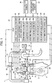
- FIG. 1 is a diagram illustrating a general configuration of the engine to which the control device of the present invention is applied.
- the engine is mounted in a non-illustrated vehicle as a traveling power source.
- Pistons 4 are each disposed in a corresponding one of cylinders 3 formed in a cylinder block 2 of an engine 1.
- Each piston 4 slides through the cylinder 3 according to rotation of a crankshaft 5.
- VVT mechanisms 13 are respectively connected to the intake and exhaust camshafts 7, 8.
- the VVT mechanisms 13, 14 consequently optionally change phases of the intake and exhaust camshafts 7, 8 with respect to the crankshaft 5 and thus change open and close timings for the intake valve 9 and the exhaust valve 10. This enables an intake and exhaust overlap amount to be adjusted.
- a common surge tank 17 is connected to intake ports 11 of the cylinders via an intake manifold 16.
- a lower end of an intake passage 18 is connected to the surge tank 17.
- the intake passage 18 is provided with an air cleaner 19, a compressor of a turbocharger 20 (supercharging means), an intercooler 21, and a throttle valve 22 arranged in this order from an upstream side.
- an upper end of an exhaust passage 24 is connected to exhaust ports 12 of the cylinders via an exhaust manifold 23.
- the exhaust passage 24 is provided with a turbine of the turbocharger 20 and a catalyst device and a muffler that are not illustrated.
- the intake manifold 16 is provided with injectors 25 corresponding to the respective cylinders.
- Each of the injectors 25 is supplied with fuel (gasoline) by a non-illustrated fuel pump.
- Ignition plugs 27 are each disposed in the corresponding cylinder of the engine 1 to face the inside of the cylinder. Each ignition plug 27 is ignited by driving of an igniter 28.
- intake air introduced into the intake passage 18 from the air cleaner 19 is pressurized by the compressor of the turbocharger 20.
- the pressurized air is cooled by the intercooler 21.
- a flow rate of the cooled air is then adjusted by the throttle valve 22.
- the intake air further passes through the surge tank 17 and is distributed to the cylinders through the intake manifold 16.
- the intake air is mixed with the fuel injected from the injector 25 while being introduced into the cylinder of the engine 1 in conjunction with opening of the intake valve 9.
- the mixed air is ignited by the ignition plug 27 and combusted.
- a resultant combustion pressure causes the crankshaft 5 to be rotationally driven via the piston 4.
- Exhaust gas resulting from combustion in each cylinder is discharged to the exhaust port 12 in conjunction with opening of the exhaust valve 10.
- the exhaust gas from each cylinder is collected by the exhaust manifold 23.
- the collected air is guided to the exhaust passage 24 to drive the turbine of the turbocharger 20.
- the air is then discharged to the outside through the catalyst device and the muffler.
- a vehicle interior is equipped with an Engine Control Unit (ECU) 31 including a non-illustrated input/output device, storage devices (ROM, RAM, BURAM, and the like) with a large number of control programs, including a nonvolatile storage device in which control programs described below are stored, a Central Processing Unit (CPU), a timer counter, and the like. These components integrally control the engine 1.
- ECU Engine Control Unit
- An input side of the ECU 31 connects to various sensors such as a throttle position sensor 32 detecting an opening degree ⁇ th of the throttle valve 22, an airflow sensor 33 detecting an intake amount V of the engine 1, a crank angle sensor 34 outputting a crank angle signal synchronizing with rotation of the engine 1, a water temperature sensor 35 detecting a cooling water temperature Tw of the engine 1, an accelerator sensor 36 detecting an accelerator opening degree ⁇ acc, and an atmospheric pressure sensor 37 (detection means) detecting an atmospheric pressure Pa. Detected information from the sensors is input to the ECU 31.
- An output side of the ECU 31 connects to various devices such as the intake and exhaust VVT mechanism 13, 14, the injector 25, the igniter 28, and a throttle actuator 38 driving opening and closing the throttle valve 22.
- the ECU 31 calculates target values for the amount of fuel injected, a fuel injection timing, a throttle opening degree, an open timing and a close timing for intake and exhaust, and the like based on detected information from the various sensors and a preset control map, and the like. Based on the target values, the ECU 31 controllably drives the various devices.
- a cause of prevention of the appropriate engine output at high altitude is a reduced exhaust pressure of the engine 1. That is, the low pressure environment at high altitude involves a reduced exhaust pressure of the engine 1 compared to a low pressure environment on a flat land. Thus, even if an intake manifold pressure condition at high altitude is the same as that on flat land, a differential pressure (intake manifold pressure - exhaust pressure) increases to make intake blow-by likely to occur.
- the inventor has concluded that an increase in overlap amount resulting from the technique in Japanese Patent Laid-Open No. 2017-25770 is a factor encouraging, on the contrary, intake blow-by, resulting in a reduced amount of air taken into the cylinders and thus reduced engine output.
- the present embodiment takes measures for preventing intake blow-by under the low pressure environment at high altitude.
- the ECU 31 includes target torque calculating unit 41 (first calculating means) for calculating a target torque Ttgt of the engine 1.
- the target torque calculating unit 41 calculates the target torque Ttgt of the engine 1 based on an engine rotation speed Ne calculated from a crank angle signal from the crank angle sensor 34, the intake amount V detected by the airflow sensor 33, the accelerator opening degree ⁇ acc detected by the accelerator sensor 36, and the like.
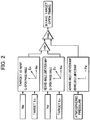
- FIG. 2 is a control block diagram of the ECU 31 configured to calculate an intake open timing.
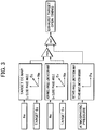
- FIG. 3 is a control block diagram of the ECU 31 configured to calculate an exhaust close timing.
- the ECU 31 includes low-pressure-environment-compatible overlap amount calculating unit 42 (increasing means) for calculating the intake and exhaust overlap amount.
- the low-pressure-environment-compatible overlap amount calculating unit 42 includes a charging efficiency calculating unit 42a (first calculating unit), a volume efficiency calculating unit 42b (second calculating unit), an intake open timing setting unit 42c (first setting unit), and an exhaust close timing setting unit 42d (second setting unit).
- the charging efficiency calculating unit 42a calculates a target charging efficiency Ec based on the target torque Ttgt calculated by the target torque calculating unit 41.
- the volume efficiency calculating unit 42b calculates a target volume efficiency Ev based on the target torque Ttgt calculated by the target torque calculating unit 41 and the atmospheric pressure Pa detected by the atmospheric pressure sensor 37.
- the intake open timing setting unit 42c calculates, based on a target IO (intake open timing) map illustrated in FIG. 2 , a target open timing (hereinafter referred to as an Ec target open phase angle) for the intake valve 9 from the target charging efficiency Ec calculated by the charging efficiency calculating unit 42a and the engine rotation speed Ne.
- the intake open timing setting unit 42c also calculates, based on a retard angle limitation map, a target open timing (hereinafter referred to as an Ev target open phase angle) for the intake valve 9 from the target volume efficiency Ev calculated by the volume efficiency calculating unit 42b and the engine rotation speed Ne.
- the intake open timing setting unit 42c selects an advance angle-side (smaller) value of the Ec target open phase angle and the Ev target open phase angle to set the selected value as a target open timing for the intake valve 9.
- the exhaust close timing setting unit 42d calculates, based on a target EC (exhaust close timing) map illustrated in FIG. 3 , a target close timing (hereinafter referred to as an Ec target close phase angle) for the exhaust valve 10 from the target charging efficiency Ec calculated by the charging efficiency calculating unit 42a and the engine rotation speed Ne.
- the exhaust close timing setting unit 42d also calculates, based on an advance angle limitation map, a target close timing (hereinafter referred to as an Ev target close phase angle) for the exhaust valve 10 from the target volume efficiency Ev calculated by the volume efficiency calculating unit 42b and the engine rotation speed Ne.
- the exhaust close timing setting unit 42d selects a retard angle-side (larger) value of the Ec target close phase angle and the Ev target close phase angle to set the selected value as a target close timing for the exhaust valve 10.
- the intake and exhaust overlap amount corresponds to a phase angle between the target open timing for the intake valve 9 set by the intake open timing setting unit 42c and the target close timing for the exhaust valve 10 set by the exhaust close timing setting unit 42d.
- the volume efficiency Ev depending on the atmospheric pressure Pa or the like, is set as a factor for the charging efficiency Ec normalized to a standard state.
- the Ev target open phase angle is calculated to be a smaller value on the advance angle side as the low pressure environment has a lower atmospheric pressure Pa.
- the Ev target close phase angle is calculated to be a larger value on the retard angle side as the low pressure environment has a lower atmospheric pressure Pa.
- the intake and exhaust overlap amount is controllably increased with decreasing atmospheric pressure of the low pressure environment.
- the ECU 31 includes increase limitation amount calculating unit 43 (second calculating means) and overlap amount increase limiting unit 44 (limiting means).
- the increase limitation amount calculating unit 43 calculates an increase limitation amount used to limit an increase in the overlap amount based on the atmospheric pressure Pa. Specifically, the increase limitation amount calculating unit 43 calculates, based on an advance angle limitation amount calculation map illustrated in FIG. 4 , an advance angle limitation amount for the open timing for the intake valve 9 as the increase limitation amount from the atmospheric pressure Pa detected by the atmospheric pressure sensor 37. The increase limitation amount calculating unit 43 further calculates, based on a retard angle limitation amount calculation map illustrated in FIG. 5 , a retard angle limitation amount for the close timing for the exhaust valve 10 as the increase limitation amount from the atmospheric pressure Pa.
- the overlap amount increase limiting unit 44 selects a retard angle-side (larger) value of the advance angle limitation amount based on the map in FIG. 4 and the target open timing for the intake valve 9 set by the intake open timing setting unit 42c to set the selected value as a final target open timing for the intake valve 9. Furthermore, as illustrated in FIG. 3 , the overlap amount increase limiting unit 44 selects an advance angle-side (smaller) value of the retard angle limitation amount based on the map in FIG. 5 and the target close timing for the exhaust valve 10 set by the exhaust close timing setting unit 42d to set the selected value as a final target close timing for the exhaust valve 10.
- a larger value on the retard angle side is calculated for an advance angle control amount and a smaller value on the advance angle side is calculated for a retard angle control amount, as the low pressure environment has a lower atmospheric pressure Pa.
- advancement of the target open timing for the intake valve 9 is limited based on the advance angle control amount and retardation of the target close timing for the exhaust valve 10 is limited based on the retard angle control amount.
- the ECU 31 includes valve timing driving control unit 45 (driving control means) controllably driving the VVT mechanisms 13, 14 based on the target open timing for the intake valve 9 resulting from the limitation based on the advance angle control amount and the target close timing for the exhaust valve 10 resulting from the limitation based on the retard angle control amount.
- valve timing driving control unit 45 driving control means controllably driving the VVT mechanisms 13, 14 based on the target open timing for the intake valve 9 resulting from the limitation based on the advance angle control amount and the target close timing for the exhaust valve 10 resulting from the limitation based on the retard angle control amount.
- FIG. 6 is a flowchart illustrating an intake open timing control routine executed by the ECU 31.
- the ECU 31 executes the routine at predetermined control intervals while the engine 1 is in operation.
- step S1 the target torque Ttgt of the engine 1 is calculated based on the sensor information such as an accelerator opening degree ⁇ acc (first calculating means).
- step S2 a needed amount of air Q needed to achieve the target torque Ttgt is calculated based on the sensor information.
- step S3 the target charging efficiency Ec, needed to achieve the needed amount of air Q, is calculated (first calculating unit).
- step S4 the target volume efficiency Ev is calculated based on the needed amount of air Q and the atmospheric pressure Pa (second calculating unit).
- step S5 the Ec target open phase angle is calculated from the target charging efficiency Ec and the engine rotation speed Ne.
- step S6 the Ev target open phase angle is calculated from the target volume efficiency Ev and the engine rotation speed Ne.
- step S7 a smaller value on the advance angle side of the Ec target open phase angle and the Ev target open phase angle is set as the target open timing for the intake valve 9 (first setting unit) .
- step S8 the advance angle control amount is calculated from the atmospheric pressure Pa based on the map in FIG. 4 (second calculating means).
- step S9 a lager value on the retard angle side of the advance angle limitation amount and the target open timing for the intake valve 9 is set as the target open timing for the intake valve 9 (limiting means).
- step S10 the intake side VVT mechanism 13 is controllably driven to achieve the target open timing (driving control means). The routine is subsequently ended.
- the ECU 31 executes an exhaust open timing control routine illustrated in FIG. 7 .
- this routine is the same as the intake open timing control routine except that the intake side is replaced with the exhaust side. Thus, only differences will be described.
- step S11 to S14 the same processing as that in steps 1 to 4 is executed. Subsequently, in step S15, an Ec target close phase angle is calculated. In step S16, an Ev target close phase angle is calculated. In step S17, a larger value on the retard angle side is set as the target close timing for the exhaust valve 10 (second setting unit). In step S18, a retard angle limitation amount is calculated based on the map in FIG. 5 (second calculating means). In step S19, a smaller value on the advance angle side is set as the target close timing for the exhaust valve 10 (limiting means). Subsequently in step S20, the exhaust side VTT mechanism 14 is controllably driven to achieve the target close timing (driving control means).
- the above-described processing of the ECU 31 controls the intake open timing and the exhaust close timing as described below.
- FIG. 8 is a characteristic diagram illustrating that the intake open timing is limited.
- FIG. 9 is a characteristic diagram illustrating that the exhaust close timing is limited.
- An ordinate axis of each figure represents a crank angle.
- An abscissa axis of each figure represents the charging efficiency Ec, correlated with the engine output and loads.
- a thin solid line indicates the Ec target open phase angle, including the target charging efficiency Ec as a factor.
- An alternate long and short dash line indicates the Ev target open phase angle, including the target volume efficiency Ev as a factor.
- An alternate long and two short dashes line indicates the advance angle limitation amount, including the atmospheric pressure Pa as a factor.
- a thick line indicates the final target open timing for the intake valve 9.
- a thin solid line indicates the Ec target close phase angle, including the target charging efficiency Ec as a factor.
- An alternate long and short dash line indicates the Ev target close phase angle, including the target volume efficiency Ev as a factor.
- An alternate long and two short dashes line indicates the retard angle limitation amount, including the atmospheric pressure Pa as a factor.
- a thick line indicates the final target close timing for the exhaust valve 10.
- a general tendency is that the intake open timing and the exhaust close timing are controllably shifted in opposite directions to increase or reduce the overlap amount. For example, in a situation where the overlap is to be increased, the intake open timing is controllably shifted toward the advance angle side, while the exhaust close timing is controllably shifted toward the retard angle side. Furthermore, the advance angle limitation and the retard angle limitation are performed in opposite directions for intake and for exhaust. For example, in a situation where the intake open timing is subjected to the advance angle limitation, the exhaust close timing is subjected to the retard angle limitation.
- a load region of the engine 1 can be roughly classified into three ranges according to the charging efficiency Ec.
- the characteristics of each phase angle are set according to a purpose for each load region.
- the Ec target open phase angle is controllably shifted toward the advance angle side and the Ec target close phase angle is controllably shifted toward the retard angle side, in order to reduce a pumping loss. This enlarges the intake and exhaust overlap.
- the Ec target open phase angle is controllably shifted toward the retard angle side and the Ec target close phase angle is controllably shifted toward the advance angle side, in order to prevent the engine from knocking.
- high engine output is required.
- air density is low due to the low pressure environment, and a sufficient turbocharging pressure fails to be obtained in a low rotation speed region. This leads to a reduction in substantial amount of air taken into the cylinders.
- the Ec target open phase angle is controllably shifted toward the advance angle side and the Ec target close phase angle is controllably shifted toward the retard angle side, in order to enlarge the intake and exhaust overlap.
- an intake close timing and the exhaust close timing are controlled without being subjected to advance angle limitation or retard angle limitation based on the above-described characteristics of the Ec target open phase angle and the Ec target close phase angle.
- the Ev target open phase angle is calculated in such a manner as to limit the retardation of the Ec target open phase angle mainly in the medium load region, based on a retard angle limitation map in FIG. 2 .
- the Ev target close phase angle is also calculated in such a manner as to limit the advancement of the Ec target close phase angle mainly in the medium load region, based on an advance angle limitation map in FIG. 3 .
- the advance angle limitation amount is calculated in such a manner as to limit the advancement of the Ec target open phase angle mainly in the high load region, based on the advance angle limitation map in FIG. 4 .
- the retard angle limitation amount is also calculated in such a manner as to limit the retardation of the Ec target close phase angle mainly in the high load region, based on the retard angle limitation map in FIG. 5 . This prevents enlargement of overlap in the high load region, thus reducing the overlap amount compared to the overlap amount in the normal pressure environment on a flat land.
- the low pressure environment at high altitude compared to a low pressure environment on a flat land, involves a reduced exhaust pressure of the engine 1 and is likely to undergo intake blow-by as a result of increased differential pressure (intake manifold pressure - exhaust pressure).
- a reduced overlap amount inhibits the intake blow-by. This also provides a sufficient amount of air taken into the cylinders, allowing prevention of a decrease in engine output, which may occur in the low pressure environment at high altitude.
- the load region where the Ec target open phase angle is subjected to the retard angle limitation and the advance angle limitation in FIG. 8 does not completely match the load region where the Ec target close phase angle is subjected to the advance angle limitation and the retard angle limitation in FIG. 9 .
- a load region including both the advance angle limitation and the retard angle limitation (denoted by E in FIG. 9 ) is present between the medium load region and the high load region.
- the original Ec target close phase angle does not involve significant intake blow-by, but the advance angle limitation for a sufficient amount of intake air increases the intake and exhaust overlap amount, promoting intake blow-by.
- the present embodiment applies the retard angle limitation to the Ec target close phase angle to limit an increase in the overlap amount. This allows intake blow-by to be inhibited to provide a sufficient amount of air taken into the cylinders.
- the engine 1 of the present embodiment involves supercharging of the turbocharger 20, which raises the intake manifold pressure to increase the likelihood of intake blow-by.
- the turbocharger 20 raises the intake manifold pressure to increase the likelihood of intake blow-by.
- the present invention is embodied in the engine 1 including the turbocharger 20.
- the present invention is not limited to this but may be applied to, for example, a naturally aspirated engine including no supercharging means.
- the VVT mechanisms 13, 14 are respectively provided for intake air and exhaust air to adjust the intake and exhaust overlap amount.
- the present invention is not limited to this.
- the VVT mechanism may be provided for one of intake air and exhaust air.
- the retard angle limitation is applied to the Ec target open phase angle using the Ev target open phase angle to achieve the advance angle limitation using the advance angle limitation amount corresponding to the atmospheric pressure Pa
- the advance angle limitation is applied to the Ec target close phase angle using the Ev target close phase angle to achieve the retard angle limitation using the retard angle limitation amount corresponding to the atmospheric pressure Pa.
- the present invention is not limited to this.
- the aspects of the present invention may include performance of only one of the retard angle limitation of the Ec target open phase angle and the advance angle limitation of the Ec target close phase angle.
- the limited side may be limited according to the atmospheric pressure Pa. Even in a case where both limitations are performed, only one side may be limited according to the atmospheric pressure Pa.
Landscapes
- Engineering & Computer Science (AREA)
- Chemical & Material Sciences (AREA)
- Combustion & Propulsion (AREA)
- Mechanical Engineering (AREA)
- General Engineering & Computer Science (AREA)
- Output Control And Ontrol Of Special Type Engine (AREA)
Applications Claiming Priority (1)
| Application Number | Priority Date | Filing Date | Title |
|---|---|---|---|
| JP2018058272A JP2019167926A (ja) | 2018-03-26 | 2018-03-26 | エンジンの制御装置 |
Publications (1)
| Publication Number | Publication Date |
|---|---|
| EP3546728A1 true EP3546728A1 (de) | 2019-10-02 |
Family
ID=65991513
Family Applications (1)
| Application Number | Title | Priority Date | Filing Date |
|---|---|---|---|
| EP19163823.8A Withdrawn EP3546728A1 (de) | 2018-03-26 | 2019-03-19 | Steuerungsvorrichtung für einen motor |
Country Status (4)
| Country | Link |
|---|---|
| US (1) | US20190293002A1 (de) |
| EP (1) | EP3546728A1 (de) |
| JP (1) | JP2019167926A (de) |
| CN (1) | CN110360013A (de) |
Cited By (1)
| Publication number | Priority date | Publication date | Assignee | Title |
|---|---|---|---|---|
| FR3144846A1 (fr) * | 2023-01-11 | 2024-07-12 | Psa Automobiles Sa | Procédé d'optimisation de la performance stabilisée en conditions extrêmes d'un moteur à combustion interne suralimenté |
Citations (5)
| Publication number | Priority date | Publication date | Assignee | Title |
|---|---|---|---|---|
| US5857437A (en) * | 1995-07-26 | 1999-01-12 | Toyota Jidosha Kabushiki Kaisha | Method of and apparatus for continuously and variably controlling valve timing of internal engine |
| US6308671B1 (en) * | 2000-09-11 | 2001-10-30 | Delphi Technologies, Inc. | Method of increasing torque and/or reducing emissions by varying the timing of intake and/or exhaust valves |
| FR2986822A1 (fr) * | 2012-02-13 | 2013-08-16 | Renault Sas | Procede de pilotage du dephasage des moyens de distribution d'un moteur a combustion interne |
| US20140007826A1 (en) * | 2012-07-04 | 2014-01-09 | Fuji Jukogyo Kabushiki Kaisha | Engine Control Device |
| JP2017025770A (ja) | 2015-07-22 | 2017-02-02 | スズキ株式会社 | 内燃機関の制御装置 |
Family Cites Families (10)
| Publication number | Priority date | Publication date | Assignee | Title |
|---|---|---|---|---|
| JPH04269339A (ja) * | 1991-02-25 | 1992-09-25 | Mazda Motor Corp | エンジンのバルブタイミング制御装置 |
| JP3351268B2 (ja) * | 1996-11-15 | 2002-11-25 | トヨタ自動車株式会社 | 内燃機関のバルブタイミング制御装置 |
| JP4232636B2 (ja) * | 2004-01-13 | 2009-03-04 | トヨタ自動車株式会社 | 内燃機関の制御装置 |
| DE112007001285B4 (de) * | 2006-05-25 | 2013-02-07 | GM Global Technology Operations LLC (n. d. Ges. d. Staates Delaware) | Verfahren und Vorrichtung zur Steuerung des Betriebs eines Motors mit homogener Kompressionszündung |
| CN101210504A (zh) * | 2006-12-28 | 2008-07-02 | 株式会社日立制作所 | 发动机进气量控制装置和发动机进气量控制方法 |
| JP4969546B2 (ja) * | 2008-09-30 | 2012-07-04 | 日立オートモティブシステムズ株式会社 | 内燃機関の制御装置および方法 |
| JP5120301B2 (ja) * | 2009-03-13 | 2013-01-16 | 三菱自動車工業株式会社 | 車両のエンジントルク演算装置 |
| US8751136B2 (en) * | 2011-07-19 | 2014-06-10 | GM Global Technology Operations LLC | Methodology to compensate the effect of humidity and altitude on HCCI combustion |
| JP2016205172A (ja) * | 2015-04-17 | 2016-12-08 | 株式会社デンソー | 内燃機関の制御装置 |
| JP6248983B2 (ja) * | 2015-05-25 | 2017-12-20 | トヨタ自動車株式会社 | 内燃機関の制御装置 |
-
2018
- 2018-03-26 JP JP2018058272A patent/JP2019167926A/ja active Pending
-
2019
- 2019-03-19 EP EP19163823.8A patent/EP3546728A1/de not_active Withdrawn
- 2019-03-25 US US16/363,634 patent/US20190293002A1/en not_active Abandoned
- 2019-03-25 CN CN201910227907.4A patent/CN110360013A/zh active Pending
Patent Citations (5)
| Publication number | Priority date | Publication date | Assignee | Title |
|---|---|---|---|---|
| US5857437A (en) * | 1995-07-26 | 1999-01-12 | Toyota Jidosha Kabushiki Kaisha | Method of and apparatus for continuously and variably controlling valve timing of internal engine |
| US6308671B1 (en) * | 2000-09-11 | 2001-10-30 | Delphi Technologies, Inc. | Method of increasing torque and/or reducing emissions by varying the timing of intake and/or exhaust valves |
| FR2986822A1 (fr) * | 2012-02-13 | 2013-08-16 | Renault Sas | Procede de pilotage du dephasage des moyens de distribution d'un moteur a combustion interne |
| US20140007826A1 (en) * | 2012-07-04 | 2014-01-09 | Fuji Jukogyo Kabushiki Kaisha | Engine Control Device |
| JP2017025770A (ja) | 2015-07-22 | 2017-02-02 | スズキ株式会社 | 内燃機関の制御装置 |
Cited By (2)
| Publication number | Priority date | Publication date | Assignee | Title |
|---|---|---|---|---|
| FR3144846A1 (fr) * | 2023-01-11 | 2024-07-12 | Psa Automobiles Sa | Procédé d'optimisation de la performance stabilisée en conditions extrêmes d'un moteur à combustion interne suralimenté |
| WO2024149941A1 (fr) * | 2023-01-11 | 2024-07-18 | Stellantis Auto Sas | Procédé d'optimisation de la performance stabilisée en conditions extrêmes d'un moteur à combustion interne suralimenté |
Also Published As
| Publication number | Publication date |
|---|---|
| CN110360013A (zh) | 2019-10-22 |
| JP2019167926A (ja) | 2019-10-03 |
| US20190293002A1 (en) | 2019-09-26 |
Similar Documents
| Publication | Publication Date | Title |
|---|---|---|
| CN102597466B (zh) | 内燃机的控制装置 | |
| JP7121332B2 (ja) | 内燃機関の制御装置 | |
| CN108625996A (zh) | 用于发动机控制的方法和系统 | |
| US9399956B2 (en) | Phaser control systems and methods for balancing mean effective pressure | |
| US9309803B2 (en) | Turbocharger compressor temperature control systems and methods | |
| JPH1061477A (ja) | 筒内噴射型火花点火式内燃エンジンの制御装置 | |
| US9303553B2 (en) | Turbo speed control for mode transitions in a dual turbo system | |
| EP3546728A1 (de) | Steuerungsvorrichtung für einen motor | |
| JP4666162B2 (ja) | 内燃機関の燃料噴射制御装置 | |
| EP3460220B1 (de) | Steuerungsvorrichtung für motor | |
| JP2013130121A (ja) | 火花点火式内燃機関の排気還流装置 | |
| US20150260286A1 (en) | Downshift indication light for fuel optimization on engines with active fuel management | |
| JP2019120204A (ja) | エンジン制御装置 | |
| JP5472481B2 (ja) | エンジンの制御装置 | |
| US9303569B2 (en) | Control device for internal combustion engine | |
| US10550771B2 (en) | Control device of internal-combustion engine | |
| EP3239502B1 (de) | Motorsteuerungsvorrichtung | |
| EP2165057B1 (de) | Steuergerät und steuerverfahren für einen verbrennungsmotor | |
| US20190376455A1 (en) | Internal combustion engine control | |
| JPH05187242A (ja) | ディーゼルエンジンの過給圧設定方法および装置 | |
| JPH03130529A (ja) | 内燃機関の吸気制御装置 | |
| JP2013072372A (ja) | 内燃機関の制御装置 | |
| JP2013142338A (ja) | 内燃機関の制御装置 |
Legal Events
| Date | Code | Title | Description |
|---|---|---|---|
| PUAI | Public reference made under article 153(3) epc to a published international application that has entered the european phase |
Free format text: ORIGINAL CODE: 0009012 |
|
| 17P | Request for examination filed |
Effective date: 20190419 |
|
| AK | Designated contracting states |
Kind code of ref document: A1 Designated state(s): AL AT BE BG CH CY CZ DE DK EE ES FI FR GB GR HR HU IE IS IT LI LT LU LV MC MK MT NL NO PL PT RO RS SE SI SK SM TR |
|
| STAA | Information on the status of an ep patent application or granted ep patent |
Free format text: STATUS: THE APPLICATION HAS BEEN WITHDRAWN |
|
| 18W | Application withdrawn |
Effective date: 20200811 |