EP3546716B1 - Method and device for controlling the regeneration of a particulate filter - Google Patents
Method and device for controlling the regeneration of a particulate filter Download PDFInfo
- Publication number
- EP3546716B1 EP3546716B1 EP19165077.9A EP19165077A EP3546716B1 EP 3546716 B1 EP3546716 B1 EP 3546716B1 EP 19165077 A EP19165077 A EP 19165077A EP 3546716 B1 EP3546716 B1 EP 3546716B1
- Authority
- EP
- European Patent Office
- Prior art keywords
- particulate filter
- oxygen
- setpoint
- oxygen content
- mass
- Prior art date
- Legal status (The legal status is an assumption and is not a legal conclusion. Google has not performed a legal analysis and makes no representation as to the accuracy of the status listed.)
- Active
Links
- 230000008929 regeneration Effects 0.000 title claims description 101
- 238000011069 regeneration method Methods 0.000 title claims description 101
- 238000000034 method Methods 0.000 title claims description 19
- 239000001301 oxygen Substances 0.000 claims description 206
- 229910052760 oxygen Inorganic materials 0.000 claims description 206
- QVGXLLKOCUKJST-UHFFFAOYSA-N atomic oxygen Chemical compound [O] QVGXLLKOCUKJST-UHFFFAOYSA-N 0.000 claims description 205
- 239000002245 particle Substances 0.000 claims description 144
- 239000004071 soot Substances 0.000 claims description 96
- 238000011144 upstream manufacturing Methods 0.000 claims description 52
- 230000001276 controlling effect Effects 0.000 claims description 15
- 230000001105 regulatory effect Effects 0.000 claims description 12
- 238000012886 linear function Methods 0.000 claims description 6
- 238000004364 calculation method Methods 0.000 claims description 5
- 230000009467 reduction Effects 0.000 claims description 5
- 230000001172 regenerating effect Effects 0.000 claims description 5
- 230000000977 initiatory effect Effects 0.000 claims 1
- 238000002485 combustion reaction Methods 0.000 description 40
- 239000007789 gas Substances 0.000 description 26
- 238000002347 injection Methods 0.000 description 12
- 239000007924 injection Substances 0.000 description 12
- 230000003647 oxidation Effects 0.000 description 12
- 238000007254 oxidation reaction Methods 0.000 description 12
- 239000003054 catalyst Substances 0.000 description 11
- 239000000446 fuel Substances 0.000 description 10
- MWUXSHHQAYIFBG-UHFFFAOYSA-N Nitric oxide Chemical compound O=[N] MWUXSHHQAYIFBG-UHFFFAOYSA-N 0.000 description 9
- 230000003197 catalytic effect Effects 0.000 description 7
- 230000008569 process Effects 0.000 description 7
- 230000001960 triggered effect Effects 0.000 description 5
- 230000033228 biological regulation Effects 0.000 description 4
- 230000007423 decrease Effects 0.000 description 4
- 229930195733 hydrocarbon Natural products 0.000 description 4
- 150000002430 hydrocarbons Chemical class 0.000 description 4
- UGFAIRIUMAVXCW-UHFFFAOYSA-N Carbon monoxide Chemical compound [O+]#[C-] UGFAIRIUMAVXCW-UHFFFAOYSA-N 0.000 description 3
- 229910002091 carbon monoxide Inorganic materials 0.000 description 3
- 239000013626 chemical specie Substances 0.000 description 3
- 230000006835 compression Effects 0.000 description 3
- 238000007906 compression Methods 0.000 description 3
- IJGRMHOSHXDMSA-UHFFFAOYSA-N Atomic nitrogen Chemical compound N#N IJGRMHOSHXDMSA-UHFFFAOYSA-N 0.000 description 2
- 239000000203 mixture Substances 0.000 description 2
- 239000000126 substance Substances 0.000 description 2
- 230000009471 action Effects 0.000 description 1
- 230000015572 biosynthetic process Effects 0.000 description 1
- 239000000567 combustion gas Substances 0.000 description 1
- 230000008878 coupling Effects 0.000 description 1
- 238000010168 coupling process Methods 0.000 description 1
- 238000005859 coupling reaction Methods 0.000 description 1
- 230000006378 damage Effects 0.000 description 1
- 238000001914 filtration Methods 0.000 description 1
- 238000004519 manufacturing process Methods 0.000 description 1
- 238000005259 measurement Methods 0.000 description 1
- 229910052757 nitrogen Inorganic materials 0.000 description 1
- 230000001590 oxidative effect Effects 0.000 description 1
- 150000002926 oxygen Chemical class 0.000 description 1
- 239000010970 precious metal Substances 0.000 description 1
- 230000002028 premature Effects 0.000 description 1
- 230000010349 pulsation Effects 0.000 description 1
- 238000000746 purification Methods 0.000 description 1
- 239000000779 smoke Substances 0.000 description 1
- 239000000243 solution Substances 0.000 description 1
- XLYOFNOQVPJJNP-UHFFFAOYSA-N water Substances O XLYOFNOQVPJJNP-UHFFFAOYSA-N 0.000 description 1
Images
Classifications
-
- F—MECHANICAL ENGINEERING; LIGHTING; HEATING; WEAPONS; BLASTING
- F01—MACHINES OR ENGINES IN GENERAL; ENGINE PLANTS IN GENERAL; STEAM ENGINES
- F01N—GAS-FLOW SILENCERS OR EXHAUST APPARATUS FOR MACHINES OR ENGINES IN GENERAL; GAS-FLOW SILENCERS OR EXHAUST APPARATUS FOR INTERNAL COMBUSTION ENGINES
- F01N9/00—Electrical control of exhaust gas treating apparatus
- F01N9/002—Electrical control of exhaust gas treating apparatus of filter regeneration, e.g. detection of clogging
-
- F—MECHANICAL ENGINEERING; LIGHTING; HEATING; WEAPONS; BLASTING
- F02—COMBUSTION ENGINES; HOT-GAS OR COMBUSTION-PRODUCT ENGINE PLANTS
- F02D—CONTROLLING COMBUSTION ENGINES
- F02D41/00—Electrical control of supply of combustible mixture or its constituents
- F02D41/02—Circuit arrangements for generating control signals
- F02D41/021—Introducing corrections for particular conditions exterior to the engine
- F02D41/0235—Introducing corrections for particular conditions exterior to the engine in relation with the state of the exhaust gas treating apparatus
- F02D41/027—Introducing corrections for particular conditions exterior to the engine in relation with the state of the exhaust gas treating apparatus to purge or regenerate the exhaust gas treating apparatus
- F02D41/029—Introducing corrections for particular conditions exterior to the engine in relation with the state of the exhaust gas treating apparatus to purge or regenerate the exhaust gas treating apparatus the exhaust gas treating apparatus being a particulate filter
-
- F—MECHANICAL ENGINEERING; LIGHTING; HEATING; WEAPONS; BLASTING
- F02—COMBUSTION ENGINES; HOT-GAS OR COMBUSTION-PRODUCT ENGINE PLANTS
- F02D—CONTROLLING COMBUSTION ENGINES
- F02D41/00—Electrical control of supply of combustible mixture or its constituents
- F02D41/02—Circuit arrangements for generating control signals
- F02D41/14—Introducing closed-loop corrections
- F02D41/1401—Introducing closed-loop corrections characterised by the control or regulation method
- F02D41/1408—Dithering techniques
-
- F—MECHANICAL ENGINEERING; LIGHTING; HEATING; WEAPONS; BLASTING
- F01—MACHINES OR ENGINES IN GENERAL; ENGINE PLANTS IN GENERAL; STEAM ENGINES
- F01N—GAS-FLOW SILENCERS OR EXHAUST APPARATUS FOR MACHINES OR ENGINES IN GENERAL; GAS-FLOW SILENCERS OR EXHAUST APPARATUS FOR INTERNAL COMBUSTION ENGINES
- F01N2430/00—Influencing exhaust purification, e.g. starting of catalytic reaction, filter regeneration, or the like, by controlling engine operating characteristics
- F01N2430/06—Influencing exhaust purification, e.g. starting of catalytic reaction, filter regeneration, or the like, by controlling engine operating characteristics by varying fuel-air ratio, e.g. by enriching fuel-air mixture
-
- F—MECHANICAL ENGINEERING; LIGHTING; HEATING; WEAPONS; BLASTING
- F01—MACHINES OR ENGINES IN GENERAL; ENGINE PLANTS IN GENERAL; STEAM ENGINES
- F01N—GAS-FLOW SILENCERS OR EXHAUST APPARATUS FOR MACHINES OR ENGINES IN GENERAL; GAS-FLOW SILENCERS OR EXHAUST APPARATUS FOR INTERNAL COMBUSTION ENGINES
- F01N2900/00—Details of electrical control or of the monitoring of the exhaust gas treating apparatus
- F01N2900/06—Parameters used for exhaust control or diagnosing
- F01N2900/14—Parameters used for exhaust control or diagnosing said parameters being related to the exhaust gas
- F01N2900/1402—Exhaust gas composition
-
- F—MECHANICAL ENGINEERING; LIGHTING; HEATING; WEAPONS; BLASTING
- F01—MACHINES OR ENGINES IN GENERAL; ENGINE PLANTS IN GENERAL; STEAM ENGINES
- F01N—GAS-FLOW SILENCERS OR EXHAUST APPARATUS FOR MACHINES OR ENGINES IN GENERAL; GAS-FLOW SILENCERS OR EXHAUST APPARATUS FOR INTERNAL COMBUSTION ENGINES
- F01N2900/00—Details of electrical control or of the monitoring of the exhaust gas treating apparatus
- F01N2900/06—Parameters used for exhaust control or diagnosing
- F01N2900/16—Parameters used for exhaust control or diagnosing said parameters being related to the exhaust apparatus, e.g. particulate filter or catalyst
- F01N2900/1602—Temperature of exhaust gas apparatus
-
- F—MECHANICAL ENGINEERING; LIGHTING; HEATING; WEAPONS; BLASTING
- F02—COMBUSTION ENGINES; HOT-GAS OR COMBUSTION-PRODUCT ENGINE PLANTS
- F02D—CONTROLLING COMBUSTION ENGINES
- F02D2200/00—Input parameters for engine control
- F02D2200/02—Input parameters for engine control the parameters being related to the engine
- F02D2200/08—Exhaust gas treatment apparatus parameters
- F02D2200/0812—Particle filter loading
-
- F—MECHANICAL ENGINEERING; LIGHTING; HEATING; WEAPONS; BLASTING
- F02—COMBUSTION ENGINES; HOT-GAS OR COMBUSTION-PRODUCT ENGINE PLANTS
- F02D—CONTROLLING COMBUSTION ENGINES
- F02D41/00—Electrical control of supply of combustible mixture or its constituents
- F02D41/02—Circuit arrangements for generating control signals
- F02D41/14—Introducing closed-loop corrections
- F02D41/1438—Introducing closed-loop corrections using means for determining characteristics of the combustion gases; Sensors therefor
- F02D41/1444—Introducing closed-loop corrections using means for determining characteristics of the combustion gases; Sensors therefor characterised by the characteristics of the combustion gases
- F02D41/1446—Introducing closed-loop corrections using means for determining characteristics of the combustion gases; Sensors therefor characterised by the characteristics of the combustion gases the characteristics being exhaust temperatures
-
- F—MECHANICAL ENGINEERING; LIGHTING; HEATING; WEAPONS; BLASTING
- F02—COMBUSTION ENGINES; HOT-GAS OR COMBUSTION-PRODUCT ENGINE PLANTS
- F02D—CONTROLLING COMBUSTION ENGINES
- F02D41/00—Electrical control of supply of combustible mixture or its constituents
- F02D41/02—Circuit arrangements for generating control signals
- F02D41/14—Introducing closed-loop corrections
- F02D41/1438—Introducing closed-loop corrections using means for determining characteristics of the combustion gases; Sensors therefor
- F02D41/1444—Introducing closed-loop corrections using means for determining characteristics of the combustion gases; Sensors therefor characterised by the characteristics of the combustion gases
- F02D41/1454—Introducing closed-loop corrections using means for determining characteristics of the combustion gases; Sensors therefor characterised by the characteristics of the combustion gases the characteristics being an oxygen content or concentration or the air-fuel ratio
- F02D41/1456—Introducing closed-loop corrections using means for determining characteristics of the combustion gases; Sensors therefor characterised by the characteristics of the combustion gases the characteristics being an oxygen content or concentration or the air-fuel ratio with sensor output signal being linear or quasi-linear with the concentration of oxygen
-
- Y—GENERAL TAGGING OF NEW TECHNOLOGICAL DEVELOPMENTS; GENERAL TAGGING OF CROSS-SECTIONAL TECHNOLOGIES SPANNING OVER SEVERAL SECTIONS OF THE IPC; TECHNICAL SUBJECTS COVERED BY FORMER USPC CROSS-REFERENCE ART COLLECTIONS [XRACs] AND DIGESTS
- Y02—TECHNOLOGIES OR APPLICATIONS FOR MITIGATION OR ADAPTATION AGAINST CLIMATE CHANGE
- Y02T—CLIMATE CHANGE MITIGATION TECHNOLOGIES RELATED TO TRANSPORTATION
- Y02T10/00—Road transport of goods or passengers
- Y02T10/10—Internal combustion engine [ICE] based vehicles
- Y02T10/40—Engine management systems
Definitions
- the present invention relates to the field of internal combustion engines, in particular direct injection diesel type engines.
- the present invention relates to the field of diesel engine pollution control, and in particular the regeneration of particulate filters.
- particulate filters Unlike oxidation catalysts, which apply continuous treatment to exhaust gases, particulate filters, acronym for "FAP", operate sequentially. During normal engine operation, the particulate filter traps polluting particles, such as soot particles emitted in the engine's combustion gases. Periodically during regeneration phases of the particle filter, for example when the mass of soot reaches a threshold, these stored particles are burnt, by the production of a controlled exotherm in the exhaust line. To be regenerated, the particulate filter requires specific combustion modes, requiring specific thermal and / or richness levels to burn the particles.
- the regeneration operations of particulate filters require a supply of heat and oxygen to generate combustion of the soot particles.
- the rate of combustion of soot particles is mainly determined by the temperature level obtained by applying particular strategies in engine control.
- the oxygen concentration in the exhaust gases is a parameter whose control is necessary to control the regeneration of the particulate filter. If there is not enough oxygen in the exhaust, combustion of the soot particles is inefficient or even non-existent. and if there is too much oxygen in the exhaust, especially with a high exhaust gas temperature and the presence of a large mass of soot particles in the particulate filter, the combustion of the soot particles n is more controlled and can lead to runaway regeneration. Regeneration runaway, that is to say an uncontrolled combustion of the soot particles, the consequence of which is the destruction of the particulate filter, which can lead to a fire in the vehicle, must be avoided. It is therefore necessary to control the temperature and the oxygen content of the exhaust gases during the regeneration phases of the particulate filter.
- document DE 10 2004 019 660 - A1 which describes an exhaust gas purification device for an internal combustion engine
- document US 2011/0073088 - A1 which describes a system for filtering and oxidizing polluting particles produced by a gasoline direct injection engine
- document FR 2 872 205 - A1 which describes an air system for regenerating a particulate filter.
- the aim of the present invention is therefore to allow regeneration of particulate filters capable of controlling the level of oxygen during regeneration.
- Another object of the invention is to reduce the cases of clogged particle filters and to increase the drain intervals.
- the subject of the invention is a method for controlling the regeneration of a particulate filter in which the average oxygen level is varied by alternating oxygen-rich phases and oxygen-poor phases throughout the duration of a particulate filter regeneration cycle.
- the oxygen level during regeneration is controlled, in particular by pulsations of oxygen in the particulate filter.
- the temperature rise rate of the particle filter is increased at the start of regeneration, then the combustion rate of the soot particles is increased at the end of regeneration.
- the regeneration time is thus reduced.
- the particulate filter regeneration cycle consists of three phases.
- the mass of the soot particles in the particulate filter is compared with a second threshold value and a first phase of the regeneration cycle is triggered when the mass of the soot particles in the particulate filter is greater than a second threshold value.
- a first temperature setpoint is imposed upstream of the particle filter, for example equal to 650 ° C, so that the temperature measured upstream of the particle filter rises gradually to a minimum temperature sufficient for start the process of burning soot particles in the particulate filter.
- the actual temperature measured upstream of the particulate filter is compared with said first temperature setpoint, and as long as the actual temperature measured upstream of the particulate filter is lower than said first temperature setpoint, a first setpoint of high oxygen level, for example equal to 15%, by alternating oxygen-rich phases and oxygen-poor phases to obtain a real oxygen level equal to the first oxygen level setpoint.
- the mass of the soot particles in the particulate filter is compared with a third threshold value.
- a second temperature set point is imposed upstream of the particulate filter, for example equal to 400 ° C, and a second reduced oxygen level setpoint is imposed, by reducing the alternation of oxygen-rich phases and oxygen-poor phases to obtain a level of oxygen. real oxygen equal to the second oxygen rate setpoint.
- a third temperature setpoint is imposed upstream of the particulate filter, and a third oxygen rate setpoint is calculated, higher than the second oxygen level setpoint, in order to accelerate the combustion rate of the remaining soot particles, by increasing the alternation of oxygen-rich phases and oxygen-poor phases.
- the oxygen level is increased linearly up to the third oxygen level set point, depending on the reduction in the mass of soot particles remaining in the particulate filter.
- the slope of the linear function is determined, for example, so as to obtain an oxygen level equal to the third oxygen level setpoint at the end of the second phase when the mass of soot is less than a fourth value of threshold that no longer presents a risk of combustion runaway.
- the mass of the soot particles in the particulate filter is compared with a fourth threshold value, and when the mass of the soot particles in the particulate filter is greater than said fourth threshold value, a third phase is triggered. regeneration of the particulate filter. During said third phase, the mass of the soot particles in the particulate filter is compared with a fifth threshold value, for example equal to 0.
- the first high oxygen level setpoint is imposed, for example equal to 15%, by alternating phases rich in oxygen and oxygen-poor phases to obtain a real oxygen level equal to the first oxygen level setpoint.
- the mass of the soot particles is, for example, calculated from the flow rate of the exhaust gases, measured by a flowmeter and from the differential pressure obtained by a sensor at the terminals of the particle filter.
- the calculation of the mass of soot particles in the particulate filter is known and will not be described further.
- the invention relates to a system for controlling the regeneration of a particulate filter comprising one comprising an oxygen level regulation module capable of managing the oxygen level in a pulsating manner by alternating rich phases. in oxygen delivering a low oxygen rate to the exhaust and oxygen-poor phases delivering a higher oxygen rate to the exhaust throughout the duration of the regeneration cycle of the particulate filter.
- the rich phases are obtained by regulating the regeneration comprising in particular, the valve of the fresh air intake, late injections into the cylinders of the engine, or even an injection of fuel directly into the exhaust duct of the engine.
- the frequency of the alternations of the phases rich and poor in oxygen content makes it possible to obtain an average oxygen rate. This avoids defining an additional specific setting to obtain a desired average rate setpoint.
- the oxygen supply accelerates the temperature rise of the catalyst upstream of the particulate filter at the start of the regeneration cycle and accelerates the combustion of soot in the particulate filter, materialized by the release of heat inside the particulate filter.
- the control system comprises a module for triggering the start of regeneration of the particulate filter comprising a comparator capable of comparing the mass of the soot particles in the particulate filter with a second threshold value. If the mass of the soot particles in the particle filter is greater than said second threshold value, a first control module of a first phase of the regeneration is activated.
- the first module can include a comparator able to compare the real temperature measured upstream of the particle filter with a first temperature setpoint, for example equal to 650 ° C. If, during the first regeneration phase, the actual temperature measured upstream of the particle filter is lower than the first temperature setpoint, the oxygen rate regulation module is activated in order to alternate phases rich in oxygen and oxygen-poor phases to obtain a real oxygen level equal to a first oxygen level setpoint.
- a comparator able to compare the real temperature measured upstream of the particle filter with a first temperature setpoint, for example equal to 650 ° C. If, during the first regeneration phase, the actual temperature measured upstream of the particle filter is lower than the first temperature setpoint, the oxygen rate regulation module is activated in order to alternate phases rich in oxygen and oxygen-poor phases to obtain a real oxygen level equal to a first oxygen level setpoint.
- the oxygen level does not need to be particularly reduced and it is possible to increase the alternation of oxygen-rich phases and oxygen-poor phases. to produce exotherm in the oxidation catalyst located upstream of the particulate filter and thus promote the rapid rise in temperature upstream of the particulate filter.
- the incursions of the rich phases (bringing unburnt substances) then poor phases (bringing oxygen) promote the release of energy on the oxidation catalyst which alternately stores these two chemical species and burns them.
- a second control module for a second regeneration phase is activated.
- the second control module includes a first comparator capable of comparing the mass of the soot particles in the particulate filter with a third threshold value, if the mass of the soot particles in the particulate filter is greater than said third threshold value , the oxygen rate regulation module is activated in order to alternate oxygen-rich phases and oxygen-poor phases to obtain a real oxygen rate equal to a second oxygen rate setpoint, lower than the first oxygen level setpoint.
- the oxygen level must therefore be reduced, by reducing the alternation of oxygen-rich phases and oxygen-poor phases to obtain a real oxygen level equal to the second oxygen level setpoint.
- the second control module comprises a calculation module capable of calculating a third oxygen level set point, greater than the second oxygen level set point.
- a calculation module capable of calculating a third oxygen level set point, greater than the second oxygen level set point.
- the third oxygen level setpoint is a linear function of the reduction in the mass of soot particles remaining in the particle filter.
- the slope of the linear function is determined, for example, so as to obtain an oxygen level equal to the third oxygen level setpoint at the end of the second phase when the mass of soot is less than a fourth value of threshold that no longer presents a risk of combustion runaway.
- the second control module includes a second comparator capable of comparing the mass of the soot particles in the particulate filter with a fourth threshold value, and whether the mass of the soot particles in the particulate filter is less than or equal at said fourth threshold value, a third control module for a third regeneration phase is activated and activates the module for regulating the oxygen level in order to alternate phases rich in oxygen and phases poor in oxygen to obtain a real oxygen rate equal to the first oxygen rate setpoint.
- the first high oxygen level setpoint for example equal to 15%, is imposed by the rate regulation module as long as the mass of the soot particles in the particulate filter is greater than a fifth threshold value, for example equal to 0.
- a fifth threshold value for example equal to 0.
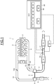
- FIG. 1 there is shown, schematically and by way of example, the general structure of an internal combustion engine 1 of a motor vehicle.
- This architecture is given by way of example and does not limit the invention to the only configuration to which the control of the regeneration according to the invention can be applied.
- the internal combustion engine 1 comprises four cylinders 2 in line, a fresh air intake manifold 3, an exhaust manifold 4 and a turbo compression system 5.
- the cylinders 2 are supplied with air through the intake manifold 3, itself supplied by a fresh air intake pipe 6 provided with an air filter 7 and the turbocharger 5 for supercharging the engine 1 in the air.
- the turbocharger 5 essentially comprises a turbine 8 driven by the exhaust gases and a compressor 9 mounted on the same axis as the turbine 8 and providing compression of the air distributed by the air filter 7, in order to increase the quantity of air admitted into the cylinders 2 of engine 1.
- the air supply line 10, connecting the compressor 9 to the intake manifold 3 includes a main intake valve 10a in order to regulate the rate of the air flow entering the manifold. admission 3.
- the latter recovers the exhaust gases resulting from the combustion and discharges the latter to the outside, via a gas exhaust duct 11 leading to the turbine 8 of the turbocharger 5 and by an exhaust line 12 downstream of said turbine 8.
- this gas exhaust duct 12 could include a discharge valve (not shown), so as to modulate the power supplied by the exhaust gases to the turbine 8.
- the exhaust line 12 shown on the figure 1 has a particulate filter 13 as well as an oxidation catalytic converter 14, called “Diesel oxidation catalyst” in Anglo-Saxon terms, arranged upstream of the particle filter 13 and essentially ensuring oxidation of the reducing molecules consisting of carbon monoxide (CO) and unburnt hydrocarbons (HC).
- This catalytic converter 14 is known to those skilled in the art and will not be described further. It will nevertheless be noted that it has a monolithic structure and is provided with channels impregnated with a catalytic phase, such as a precious metal, and having a large contact surface with the exhaust gases.
- the monolith entering into the constitution of the catalytic converter 14 can be integrated into the particulate filter 13 in order to achieve a coupling between the post-treatment of the exhaust gases by oxidation of carbon monoxide and unburnt hydrocarbons in the post-treatment. particles.
- the oxidation catalytic converter 14 one could provide another unit for treating exhaust gas effluents, in particular a nitrogen oxide trap associated with the particulate filter 13, making it possible to reduce nitrogen oxides. (NOx) emitted by engine 1 in harmless molecules of nitrogen and water under the action of hydrocarbons coming from the engine.
- a high-pressure exhaust gas recirculation circuit 15, comprising a part of the supply circuit 10 of the engine 1 and a part of the exhaust circuit 11, recovers a part of the exhaust gases and reinjects them into the manifold air intake 3, in order to limit the quantity of nitrogen oxides produced by combustion while preventing the formation of smoke in the exhaust gases.
- the first recirculation circuit 16 essentially comprises a heat exchanger 16.
- a second low-pressure exhaust gas recirculation circuit could also be provided (not shown), capable of recovering part of the exhaust gas downstream of the particulate filter 13 and of reinjecting them into the turbo compression system 5.
- a second recirculation circuit could include, without limitation, a filter, a cooler and a valve for adjusting the flow of cooled recirculated exhaust gas. The cooled recirculated exhaust gases are then mixed with the fresh air admitted into the line in a mixer (not shown).
- An oxygen sensor 20, of the proportional type is located between the catalytic converter 14 and the particulate filter 13, at the input of the particulate filter 13.
- the output signal of the oxygen sensor 20 is formed in a electronic control unit, "ECU” or on-board computer 25.
- This signal contains information on the residual oxygen content Ox of the exhaust gases and also on the current ratio of fuel and air of the mixture sucked by the engine 1
- the air / fuel ratio is also called “richness”.
- the residual oxygen content can come from an oxygen sensor located upstream of the catalytic converter 14. It can also be calculated from an air flow rate value and a flow rate value of fuel introduced into the engine.
- a differential pressure sensor 22 is arranged at the terminals of the particulate filter 13 in order to determine the mass M of soot particles in the particle filter 13 and a temperature sensor 23 before turbine T av_T is placed directly upstream of the turbine 8.
- the control unit 25 essentially ensures the control of the operation of the engine 1, in particular the control of the regeneration of the particulate filter 13.
- the electronic control unit 25 comprises for this purpose a system 30 for controlling the regeneration of the particulate filter 13 comprising a module 31 for regulating the oxygen rate capable of managing the oxygen rate in a pulsating manner by alternating phases. so-called “rich” delivering a low rate of oxygen to the exhaust and so-called “lean” phases delivering a higher rate of oxygen to the exhaust, and this throughout the duration of the cycle R of regeneration of the particulate filter 13.
- the rich phases are obtained by regulating the regeneration comprising in particular, the valve of the fresh air intake 10a, late injections into the cylinders 2 of the engine 1, or even an injection of fuel directly into the exhaust duct 12. of the motor.
- the frequency of the alternations of the phases rich and poor in oxygen content makes it possible to obtain an average oxygen rate.
- the oxygen supply makes it possible to accelerate the rise in temperature of the catalyst 14 upstream of the particle filter 13 at the start of the regeneration cycle R and to accelerate the combustion of the soot particles in the particle filter 13, materialized by a release of heat inside the particulate filter 13.
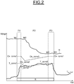
- the regeneration cycle of the particulate filter 13 comprises three phases P1, P2, P3 visible on the figure 2 .
- the first phase P1 of the regeneration cycle R of the particulate filter 13 corresponds to the start of the regeneration of said particulate filter, more precisely to the phase of the temperature rise of the filter at the start of the regeneration.
- the temperature T av_FAP upstream of the particle filter 13 gradually rises to a first threshold value T1, for example between 600 ° C and 700 ° C.
- the first threshold value T1 corresponds to the minimum temperature sufficient to initiate the process of combustion of the soot particles in the particle filter 13.
- the second phase P2 of the regeneration cycle R of the particulate filter 13 corresponds to the regeneration of the particulate filter 13.
- the mass M of soot particles decreases, as does the risk of combustion runaway.
- the third and last regeneration phase P3 of the regeneration cycle R of the particulate filter 13 corresponds to the end of the regeneration of said particulate filter.
- the mass M of soot particles remaining in the particulate filter 13 no longer presents a risk of combustion runaway.
- the control system 30 comprises a module 32 for triggering the start of regeneration of the particulate filter 13.
- Said trigger module 32 comprises a comparator (not shown) capable of comparing the mass of the soot particles M in the particulate filter 13. with a second threshold value M1. If the mass of the soot particles M in the particle filter 13 is greater than a second threshold value M1, the first regeneration phase P1 is initiated.
- the regeneration control system 30 comprises a first module 33 for controlling the regeneration during the first phase P1.
- the first module 33 comprises a comparator (not shown) capable of comparing the real temperature T av_FAP measured by the sensor 20 upstream of the particle filter 13 with a first temperature set point T_cons1 upstream of the particle filter 13, for example equal to 650 ° C.
- the module 31 for regulating the oxygen rate is activated in order to alternate phases rich in oxygen and phases poor in oxygen to obtain a real oxygen level equal to a first oxygen level setpoint Ox_cons1.
- the risk of runaway combustion during this first phase P1 being zero, the temperature not being sufficient to initiate the combustion of the soot particles, the oxygen level does not need to be particularly reduced and the alternation of the oxygen-rich phases and the oxygen-poor phases can be increased to produce exotherm in the oxidation catalyst 14 located upstream of the particulate filter 13 and thus promote the rapid rise in temperature upstream of the particle filter 13.
- the incursions of the rich phases (providing unburnt substances) then poor phases (providing oxygen) promote the release of energy on the oxidation catalyst 14 which alternately stores these two chemical species and burns them.
- the control system 30 activates a second control module 34 of the second regeneration phase P2.
- the second control module 34 comprises a comparator (not shown) capable of comparing the mass M of soot particles in the particulate filter 13 with a third threshold value M2.
- the module 31 for regulating the oxygen level is activated in order to alternate phases rich in oxygen and phases poor in oxygen. oxygen to obtain a real oxygen rate equal to a second oxygen rate setpoint Ox_cons2, lower than the first oxygen rate setpoint Ox_cons1.
- the oxygen level Ox must therefore be reduced, by reducing the alternation of the oxygen-rich phases and the oxygen-poor phases in order to obtain a real oxygen level equal to the second oxygen level setpoint Ox_cons2.
- a module 35 for calculating a third oxygen level setpoint Ox_cons3, greater than the second rate setpoint oxygen Ox_cons2, is activated.
- This third oxygen rate setpoint Ox_cons3 makes it possible to accelerate the rate of combustion of the remaining soot particles, by increasing the alternation of phases rich in oxygen and phases poor in oxygen.
- the oxygen level Ox is thus increased linearly as a function of the decrease in the mass M of soot particles remaining in the particulate filter 13.
- the slope of the linear function is determined, for example, so as to obtain an oxygen rate equal to the third oxygen rate setpoint Ox_cons3 at the end of the second phase P2 when the mass of soot is less than a fourth threshold value M3 no longer presenting a risk of combustion runaway.
- control system 31 comprises a third module 36 for controlling the third regeneration phase P3.
- the third control module 36 is activated, said masses being compared in a second comparator of the second control module 34.
- the third control module 36 activates the module 31 for regulating the oxygen level in order to impose the first high oxygen level setpoint Ox_cons1, for example equal to 15%, as long as the mass of the soot particles M in the particle filter 13 is greater than a fifth threshold value M4, for example equal to 0.
- a fifth threshold value M4 for example equal to 0.
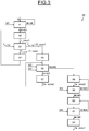
- the figure 3 represents an implementation flowchart of a method 40 for controlling the regeneration of the particulate filter 13 capable of managing the oxygen level in a pulsating manner by alternating so-called “rich” phases delivering an oxygen level to the weak exhaust and so-called “poor” phases delivering a stronger rate of oxygen to the exhaust.
- the rich phases are obtained by regulating the regeneration comprising in particular, the valve of the fresh air intake, late injections into the cylinders of the engine, or even an injection of fuel directly into the exhaust duct of the engine.
- the frequency of the alternations of the phases rich and poor in oxygen content makes it possible to obtain an average oxygen rate.
- the supply of oxygen makes it possible to accelerate the rise in temperature of the catalyst 14 upstream of the particulate filter 13 at the start of the regeneration cycle and to accelerate the combustion of the soot particles in the particulate filter 13, materialized by a release of heat inside particulate filter 13.
- the regeneration cycle of the particulate filter 13 comprises three phases P1, P2, P3 visible on the figure 2 .
- the start of regeneration R can be triggered when the mass of the soot particles M in the particulate filter 13 is greater than a second threshold value M1.
- a second threshold value M1 the mass of the soot particles M in the particle filter 13 is compared with a second threshold value M1.
- the first regeneration phase P1 R corresponds to the start of regeneration of the particle filter 13.
- the temperature T av_FAP upstream of the particle filter 13 gradually rises to a first threshold value T1, for example between 600 ° C and 700 ° C.
- the first threshold value T1 corresponds to the minimum temperature sufficient to initiate the process of combustion of the soot particles in the particle filter 13.
- the electronic control unit 25 imposes, via the control system 30, in step 42, a first temperature setpoint T_cons1 upstream of the particle filter 13, for example equal to 650 ° C. .
- step 53 the actual temperature measured T av_FAP is compared upstream of the particle filter 13 with said first temperature set point T_cons1.
- the control system 30 controls, in step 54, the first regeneration phase P1 by imposing a first high oxygen rate setpoint Ox_cons1, for example equal to 15%. For this, the control system 30 alternates phases rich in oxygen and phases poor in oxygen to obtain a real oxygen level equal to the first oxygen level setpoint Ox_cons1.
- the oxygen level does not need to be particularly reduced and it is possible to increase the alternation of phases rich in oxygen and phases poor in oxygen.
- oxygen to produce exotherm in the oxidation catalyst 14 located upstream of the particulate filter 13 and thus promote the rapid rise in temperature upstream of the particulate filter 13.
- the incursions of the rich phases (bringing unburnt) then poor (providing oxygen) promote the release of energy on the oxidation catalyst 14 which alternately stores these two chemical species and burns them.
- the control system 30 controls, in step 55, the second regeneration phase P2.
- the second phase P2 corresponds to the regeneration of the particle filter 13.
- the temperature T av_FAP upstream of the particle filter 13 is greater than or equal to the first temperature set point T_cons1 upstream of the particle filter 13 imposed by the control system 30.
- the mass M of soot particles decreases, as does the risk of combustion runaway.
- the control system 30 compares, in step 56, the mass of the soot particles M in the particle filter 13 with a third threshold value M2.
- the risk of combustion runaway is maximum.
- the control system 30 imposes, in step 57, a second temperature setpoint T_cons2 upstream of the particle filter 13, for example equal to 400 ° C. and imposes a second reduced oxygen rate setpoint Ox_cons2, by reducing the alternation of oxygen-rich phases and oxygen-poor phases to obtain a real oxygen rate equal to the second oxygen rate setpoint Ox_cons2.
- the control system 30 imposes, in step 58, a third temperature setpoint T_cons3 upstream of the particulate filter 13, and also calculates a third setpoint of oxygen rate Ox_cons3, greater than the second oxygen rate setpoint Ox_cons2 in order to accelerate the rate of combustion of the remaining soot particles, by increasing the alternation of phases rich in oxygen and phases poor in oxygen.
- the oxygen level Ox is thus increased linearly as a function of the reduction in the mass M of soot particles remaining in the particle filter 13.
- the slope of the linear function is determined, for example, so as to obtain an oxygen rate equal to the third oxygen rate setpoint Ox_cons3 at the end of the second phase P2 when the mass of soot is less than a fourth threshold value M3 no longer presenting a risk of combustion runaway.
- step 59 the mass M of soot is compared with a fourth threshold value M3.
- step 60 When the mass of soot is less than or equal to said fourth threshold value M3, in step 60, the third and last phase P3 of regeneration which corresponds to the end of the regeneration of the particle filter 13. In this third phase P3, the mass M of soot particles remaining in the particle filter 13 no longer presents a risk of combustion runaway .
- step 61 the mass M of the soot particles in the particulate filter 13 is compared with a fifth threshold value M4, for example equal to 0.
- a fifth threshold value M4 for example equal to 0.
- the control system 30 imposes, in step 62, the first high oxygen rate setpoint Ox_cons1, for example equal to 15%, by alternating phases rich in oxygen and phases poor in oxygen to obtain a real oxygen level equal to the first oxygen level setpoint Ox_cons1.
- the mass M of the soot particles is, for example, calculated from the flow rate of the exhaust gases, measured by a flowmeter (not shown) and from the differential pressure obtained by the sensor 22 at the terminals of the particle filter 13.
- the calculation of the mass M of the soot particles in the particulate filter 13 is known and will not be described further.
- the average oxygen rate is varied by alternating oxygen-rich phases and oxygen-poor phases throughout the duration of the regeneration cycle.
- the present invention allows a continuous linear evolution of the oxygen level as a function of the decrease in the mass of soot particles in the particulate filter.
- the maximum oxygen level is not limited throughout the regeneration process of the particulate filter in order to limit the combustion runaway. In fact, this oxygen level in the particle filter is constantly changing here.
Description
La présente invention concerne le domaine des moteurs à combustion interne, notamment des moteurs de type Diesel à injection directe.The present invention relates to the field of internal combustion engines, in particular direct injection diesel type engines.
Plus particulièrement, la présente invention concerne le domaine de la dépollution des moteurs Diesel, et notamment la régénération des filtres à particules.More particularly, the present invention relates to the field of diesel engine pollution control, and in particular the regeneration of particulate filters.
Contrairement aux catalyseurs d'oxydation, qui appliquent un traitement continu aux gaz d'échappement, les filtres à particules, d'acronyme « FAP », fonctionnement de manière séquentielle. Pendant le fonctionnement normal du moteur, le filtre à particules piège les particules polluantes, telles que les particules de suies émises dans les gaz de combustion du moteur. Périodiquement lors de phases de régénération du filtre à particules, par exemple quand la masse de suies atteint un seuil, ces particules stockées sont brûlées, par la production d'un exotherme contrôlé dans la ligne d'échappement. Pour être régénéré, le filtre à particules nécessite des modes de combustion spécifiques, requérant des niveaux de thermique et/ou de richesse déterminés pour brûler les particules.Unlike oxidation catalysts, which apply continuous treatment to exhaust gases, particulate filters, acronym for "FAP", operate sequentially. During normal engine operation, the particulate filter traps polluting particles, such as soot particles emitted in the engine's combustion gases. Periodically during regeneration phases of the particle filter, for example when the mass of soot reaches a threshold, these stored particles are burnt, by the production of a controlled exotherm in the exhaust line. To be regenerated, the particulate filter requires specific combustion modes, requiring specific thermal and / or richness levels to burn the particles.
Les opérations de régénération des filtres à particules nécessitent un apport de chaleur et d'oxygène pour générer la combustion des particules de suies.The regeneration operations of particulate filters require a supply of heat and oxygen to generate combustion of the soot particles.
La vitesse de combustion des particules de suies est principalement déterminée par le niveau de température obtenu en appliquant des stratégies particulières dans le contrôle moteur.The rate of combustion of soot particles is mainly determined by the temperature level obtained by applying particular strategies in engine control.
La concentration en oxygène des gaz d'échappement est un paramètre dont le contrôle est nécessaire pour maîtriser la régénération du filtre à particules. S'il n'y a pas assez d'oxygène à l'échappement, la combustion des particules de suies est inefficace, voire inexistante, et s'il y a trop d'oxygène à l'échappement, notamment avec une température des gaz d'échappement élevée et en présence d'une masse importante de particules de suies dans le filtre à particule, la combustion des particules de suies n'est plus maîtrisée et peut aboutir à l'emballement de la régénération. Il faut en effet éviter l'emballement de la régénération, c'est-à-dire une combustion incontrôlée des particules de suies, dont la conséquence est la destruction du filtre à particules, qui peut entrainer un incendie du véhicule. Il est donc nécessaire de contrôler la température et le taux d'oxygène des gaz d'échappement pendant les phases de régénération du filtre à particules.The oxygen concentration in the exhaust gases is a parameter whose control is necessary to control the regeneration of the particulate filter. If there is not enough oxygen in the exhaust, combustion of the soot particles is inefficient or even non-existent. and if there is too much oxygen in the exhaust, especially with a high exhaust gas temperature and the presence of a large mass of soot particles in the particulate filter, the combustion of the soot particles n is more controlled and can lead to runaway regeneration. Regeneration runaway, that is to say an uncontrolled combustion of the soot particles, the consequence of which is the destruction of the particulate filter, which can lead to a fire in the vehicle, must be avoided. It is therefore necessary to control the temperature and the oxygen content of the exhaust gases during the regeneration phases of the particulate filter.
Afin d'éviter l'emballement de la régénération, il est courant de définir un réglage situé dans une plage admissible, par exemple autour de 8%, afin de contrôler l'injection de carburant et l'ouverture et la fermeture de la vanne d'admission d'air, de sorte à limiter le taux d'oxygène tout au long de la régénération.In order to avoid runaway regeneration, it is common practice to set a setting within an allowable range, for example around 8%, in order to control the fuel injection and the opening and closing of the valve. 'air intake, so as to limit the oxygen level throughout the regeneration.
Toutefois, une telle précaution est généralement excessive.However, such a precaution is usually excessive.
On peut se référer à cet égard au document
On peut également se référer au document
De plus, il n'y a aucune variabilité du taux d'oxygène, hormis sur des zones de fonctionnement à risque du moteur nécessitant des taux d'oxygène bas. Le taux d'oxygène est alors réduit sur toute la durée de la régénération.In addition, there is no variability in the oxygen level, except in areas of high risk engine operation requiring low oxygen levels. The oxygen level is then reduced over the entire regeneration period.
Une telle solution ne permet pas d'optimiser l'efficacité des régénérations. Or, les contraintes liées par les normes européennes « EURO 6c » et suivantes, ainsi que la sévérité des roulages impliquent la nécessité d'améliorer les efficacités de la régénération des filtres à particules, afin de limiter les risques de filtres à particules colmatés, ainsi que les alertes de vidange prématurées.Such a solution does not make it possible to optimize the efficiency of the regenerations. However, the constraints linked by European standards "EURO 6c" and following, as well as the severity of the driving conditions imply the need to improve the efficiency of the regeneration of particle filters, in order to limit the risks of clogged particle filters, as well as as premature drain alerts.
On connait également le document
Enfin, on connait le document
On connait également le document
Il existe un besoin d'améliorer les procédés et systèmes de régénération des filtres à particules, notamment leur efficacité, dans le but de réduire le temps de régénération.There is a need to improve the methods and systems for regenerating particulate filters, in particular their efficiency, in order to reduce the regeneration time.
Le but de la présente invention est donc de permettre une régénération des filtres à particules capable de maitriser le taux d'oxygène en cours de régénération.The aim of the present invention is therefore to allow regeneration of particulate filters capable of controlling the level of oxygen during regeneration.
Un autre objectif de l'invention est de réduire les cas de filtres à particules colmatés et d'accroître les intervalles de vidange.Another object of the invention is to reduce the cases of clogged particle filters and to increase the drain intervals.
L'invention a pour objet un procédé de commande de la régénération d'un filtre à particules dans lequel on fait varier le taux d'oxygène moyen en alternant des phases riches en oxygène et des phases pauvres en oxygène pendant toute la durée d'un cycle de régénération du filtre à particules.The subject of the invention is a method for controlling the regeneration of a particulate filter in which the average oxygen level is varied by alternating oxygen-rich phases and oxygen-poor phases throughout the duration of a particulate filter regeneration cycle.
Ainsi, on maitrise le taux d'oxygène en cours de régénération, notamment par pulsations d'oxygène dans le filtre à particules.Thus, the oxygen level during regeneration is controlled, in particular by pulsations of oxygen in the particulate filter.
Grâce au fractionnement de la concentration en oxygène sur la totalité du cycle de régénération, on obtient une évolution continue, par exemple, une augmentation linéaire, du taux d'oxygène en fonction de la masse de particules de suies.By splitting the oxygen concentration over the entire regeneration cycle, a continuous evolution, for example a linear increase, of the oxygen level as a function of the mass of soot particles is obtained.
Ainsi, la vitesse de montée en température du filtre à particules est augmentée en début de régénération, puis la vitesse de combustion des particules de suies est augmentée en fin de régénération.Thus, the temperature rise rate of the particle filter is increased at the start of regeneration, then the combustion rate of the soot particles is increased at the end of regeneration.
Le temps de régénération est ainsi réduit.The regeneration time is thus reduced.
Le cycle de régénération du filtre à particules comprend trois phases.The particulate filter regeneration cycle consists of three phases.
Selon le procédé, on compare la masse des particules de suies dans le filtre à particules avec une deuxième valeur de seuil et on déclenche une première phase du cycle de régénération lorsque la masse des particules de suies dans le filtre à particules est supérieure à une deuxième valeur de seuil. Lors du déclenchement de la régénération, on impose une première consigne de température en amont du filtre à particules, par exemple égale à 650°C, afin que la température mesurée en amont du filtre à particules monte progressivement jusqu'à une température minimale suffisante pour amorcer le processus de combustion des particules de suies dans le filtre à particules.According to the method, the mass of the soot particles in the particulate filter is compared with a second threshold value and a first phase of the regeneration cycle is triggered when the mass of the soot particles in the particulate filter is greater than a second threshold value. When the regeneration is triggered, a first temperature setpoint is imposed upstream of the particle filter, for example equal to 650 ° C, so that the temperature measured upstream of the particle filter rises gradually to a minimum temperature sufficient for start the process of burning soot particles in the particulate filter.
Par exemple, on compare la température réelle mesurée en amont du filtre à particules avec ladite première consigne de température, et tant que la température réelle mesurée en amont du filtre à particules est inférieure à ladite première consigne de température, on impose une première consigne de taux d'oxygène élevée, par exemple égale à 15%, en alternant des phases riches en oxygène et des phases pauvres en oxygène pour obtenir un taux d'oxygène réel égal à la première consigne de taux d'oxygène.For example, the actual temperature measured upstream of the particulate filter is compared with said first temperature setpoint, and as long as the actual temperature measured upstream of the particulate filter is lower than said first temperature setpoint, a first setpoint of high oxygen level, for example equal to 15%, by alternating oxygen-rich phases and oxygen-poor phases to obtain a real oxygen level equal to the first oxygen level setpoint.
Selon le procédé, lorsque la température mesurée en amont du filtre à particules est supérieure ou égale à la première consigne de température en amont du filtre à particules, on déclenche une deuxième phase de régénération du filtre à particules.Depending on the process, when the temperature measured upstream of the particle filter is greater than or equal to the first setpoint of temperature upstream of the particle filter, a second phase of regeneration of the particle filter is triggered.
Lors de la deuxième phase de régénération, on compare la masse des particules de suies dans le filtre à particules avec une troisième valeur de seuil. Tant que la masse des particules de suies dans le filtre à particules est supérieure à ladite troisième valeur de seuil et que la température mesurée en amont du filtre à particules est supérieure ou égale à la première consigne de température, on impose une deuxième consigne de température en amont du filtre à particules, par exemple égale à 400°C, et on impose une deuxième consigne de taux d'oxygène réduite, en réduisant l'alternance des phases riches en oxygène et des phases pauvres en oxygène pour obtenir un taux d'oxygène réel égal à la deuxième consigne de taux d'oxygène.During the second regeneration phase, the mass of the soot particles in the particulate filter is compared with a third threshold value. As long as the mass of the soot particles in the particle filter is greater than said third threshold value and the temperature measured upstream of the particle filter is greater than or equal to the first temperature set point, a second temperature set point is imposed upstream of the particulate filter, for example equal to 400 ° C, and a second reduced oxygen level setpoint is imposed, by reducing the alternation of oxygen-rich phases and oxygen-poor phases to obtain a level of oxygen. real oxygen equal to the second oxygen rate setpoint.
Lors de la deuxième phase de régénération et lorsque la masse de suies est inférieure ou égale à ladite troisième valeur de seuil, on impose une troisième consigne de température en amont du filtre à particules, et on calcule une troisième consigne de taux d'oxygène, supérieure à la deuxième consigne de taux d'oxygène, afin d'accélérer la vitesse de combustion des particules de suies restantes, en augmentant l'alternance des phases riches en oxygène et des phases pauvres en oxygène.During the second regeneration phase and when the mass of soot is less than or equal to said third threshold value, a third temperature setpoint is imposed upstream of the particulate filter, and a third oxygen rate setpoint is calculated, higher than the second oxygen level setpoint, in order to accelerate the combustion rate of the remaining soot particles, by increasing the alternation of oxygen-rich phases and oxygen-poor phases.
Selon le procédé, on augmente le taux d'oxygène linéairement jusqu'à la troisième consigne de taux d'oxygène, en fonction de la diminution de la masse de particules de suies restantes dans le filtre à particules.According to the process, the oxygen level is increased linearly up to the third oxygen level set point, depending on the reduction in the mass of soot particles remaining in the particulate filter.
La pente de la fonction linéaire est déterminée, par exemple, de manière à obtenir un taux d'oxygène égal à la troisième consigne de taux d'oxygène à la fin de la deuxième phase lorsque la masse de suies est inférieur à une quatrième valeur de seuil ne présentant plus de risque d'emballement de la combustion.The slope of the linear function is determined, for example, so as to obtain an oxygen level equal to the third oxygen level setpoint at the end of the second phase when the mass of soot is less than a fourth value of threshold that no longer presents a risk of combustion runaway.
Ensuite, on compare la masse des particules de suies dans le filtre à particules avec une quatrième valeur de seuil, et lorsque la masse des particules de suies dans le filtre à particules est supérieure à ladite quatrième valeur de seuil, on déclenche une troisième phase de régénération du filtre à particules. Lors de ladite troisième phase, on compare la masse des particules de suies dans le filtre à particules avec une cinquième valeur de seuil, par exemple égale à 0.Then, the mass of the soot particles in the particulate filter is compared with a fourth threshold value, and when the mass of the soot particles in the particulate filter is greater than said fourth threshold value, a third phase is triggered. regeneration of the particulate filter. During said third phase, the mass of the soot particles in the particulate filter is compared with a fifth threshold value, for example equal to 0.
Tant que la masse des particules de suies dans le filtre à particules est supérieure à ladite cinquième valeur de seuil, on impose la première consigne de taux d'oxygène élevée, par exemple égale à 15%, en alternant des phases riches en oxygène et des phases pauvres en oxygène pour obtenir un taux d'oxygène réel égal à la première consigne de taux d'oxygène.As long as the mass of the soot particles in the particulate filter is greater than said fifth threshold value, the first high oxygen level setpoint is imposed, for example equal to 15%, by alternating phases rich in oxygen and oxygen-poor phases to obtain a real oxygen level equal to the first oxygen level setpoint.
La masse des particules de suies est, par exemple, calculée à partir du débit des gaz d'échappement, mesuré par un débitmètre et de la pression différentielle obtenue par un capteur aux bornes du filtre à particules. Le calcul de la masse des particules de suies dans le filtre à particules est connu et ne sera pas davantage décrit.The mass of the soot particles is, for example, calculated from the flow rate of the exhaust gases, measured by a flowmeter and from the differential pressure obtained by a sensor at the terminals of the particle filter. The calculation of the mass of soot particles in the particulate filter is known and will not be described further.
Selon un deuxième aspect, l'invention concerne un système de commande de la régénération d'un filtre à particules comprenant un comprenant un module de régulation du taux d'oxygène capable de gérer le taux d'oxygène de manière pulsatoire en alternant des phases riches en oxygène délivrant un taux d'oxygène faible à l'échappement et des phases pauvres en oxygène délivrant un taux d'oxygène plus fort à l'échappement pendant toute la durée du cycle de régénération du filtre à particules.According to a second aspect, the invention relates to a system for controlling the regeneration of a particulate filter comprising one comprising an oxygen level regulation module capable of managing the oxygen level in a pulsating manner by alternating rich phases. in oxygen delivering a low oxygen rate to the exhaust and oxygen-poor phases delivering a higher oxygen rate to the exhaust throughout the duration of the regeneration cycle of the particulate filter.
Les phases riches sont obtenues par un réglage de la régénération comprenant notamment, le vannage de l'admission d'air frais, des injections tardives dans les cylindres du moteur, voire une injection de carburant directement dans le conduit d'échappement du moteur.The rich phases are obtained by regulating the regeneration comprising in particular, the valve of the fresh air intake, late injections into the cylinders of the engine, or even an injection of fuel directly into the exhaust duct of the engine.
La fréquence des alternances des phases riches et pauvres en taux d'oxygène permet d'obtenir un taux d'oxygène moyen. Ainsi, on évite de définir un réglage spécifique supplémentaire pour obtenir une consigne de taux moyen souhaitée.The frequency of the alternations of the phases rich and poor in oxygen content makes it possible to obtain an average oxygen rate. This avoids defining an additional specific setting to obtain a desired average rate setpoint.
L'apport en oxygène permet d'accélérer la montée en température du catalyseur en amont du filtre à particules au début du cycle de régénération et d'accélérer la combustion des particules de suies dans le filtre à particules, matérialisée par un dégagement de chaleur à l'intérieur du filtre à particules.The oxygen supply accelerates the temperature rise of the catalyst upstream of the particulate filter at the start of the regeneration cycle and accelerates the combustion of soot in the particulate filter, materialized by the release of heat inside the particulate filter.
Le système de commande comprend un module de déclenchement du début de la régénération du filtre à particules comprenant un comparateur capable de comparer la masse des particules de suies dans le filtre à particules avec une deuxième valeur de seuil. Si la masse des particules de suies dans le filtre à particules est supérieure à ladite deuxième valeur de seuil, un premier module de commande d'une première phase de la régénération est activé.The control system comprises a module for triggering the start of regeneration of the particulate filter comprising a comparator capable of comparing the mass of the soot particles in the particulate filter with a second threshold value. If the mass of the soot particles in the particle filter is greater than said second threshold value, a first control module of a first phase of the regeneration is activated.
Le premier module peut comprendre un comparateur apte à comparer la température réelle mesurée en amont du filtre à particules avec une première consigne de température, par exemple égale à 650°C. Si, pendant la première phase de régénération, la température réelle mesurée en amont du filtre à particules est inférieure à la première consigne de température, le module de régulation du taux d'oxygène est activé afin d'alterner des phases riches en oxygène et des phases pauvres en oxygène pour obtenir un taux d'oxygène réel égal à une première consigne de taux d'oxygène.The first module can include a comparator able to compare the real temperature measured upstream of the particle filter with a first temperature setpoint, for example equal to 650 ° C. If, during the first regeneration phase, the actual temperature measured upstream of the particle filter is lower than the first temperature setpoint, the oxygen rate regulation module is activated in order to alternate phases rich in oxygen and oxygen-poor phases to obtain a real oxygen level equal to a first oxygen level setpoint.
En effet, le risque d'emballement de la combustion lors de cette première phase étant nul, le taux d'oxygène ne nécessite pas d'être particulièrement réduit et on peut augmenter l'alternance des phases riches en oxygène et des phases pauvres en oxygène pour produire de l'exotherme dans le catalyseur d'oxydation situé en amont du filtre à particules et favoriser ainsi la montée en température rapide en amont du filtre à particules. En effet, les incursions des phases riches (apportant des imbrûlés) puis pauvres (apportant de l'oxygène) favorisent le dégagement d'énergie sur le catalyseur d'oxydation qui stocke alternativement ces deux espèces chimiques et les brûle.Indeed, the risk of runaway combustion during this first phase being zero, the oxygen level does not need to be particularly reduced and it is possible to increase the alternation of oxygen-rich phases and oxygen-poor phases. to produce exotherm in the oxidation catalyst located upstream of the particulate filter and thus promote the rapid rise in temperature upstream of the particulate filter. In fact, the incursions of the rich phases (bringing unburnt substances) then poor phases (bringing oxygen) promote the release of energy on the oxidation catalyst which alternately stores these two chemical species and burns them.
Lorsque, pendant la première phase de régénération, la température réelle mesurée en amont du filtre à particules est supérieure ou égale à la première consigne de température, un deuxième module de commande d'une deuxième phase de régénération est activé.When, during the first regeneration phase, the actual temperature measured upstream of the particulate filter is greater than or equal to the first temperature setpoint, a second control module for a second regeneration phase is activated.
Le deuxième module de commande comprend un premier comparateur capable de comparer la masse des particules de suies dans le filtre à particules avec une troisième valeur de seuil, si la masse des particules de suies dans le filtre à particules est supérieure à ladite troisième valeur de seuil, le module de régulation du taux d'oxygène est activé afin d'alterner des phases riches en oxygène et des phases pauvres en oxygène pour obtenir un taux d'oxygène réel égal à une deuxième consigne de taux d'oxygène, inférieure à la première consigne de taux d'oxygène.The second control module includes a first comparator capable of comparing the mass of the soot particles in the particulate filter with a third threshold value, if the mass of the soot particles in the particulate filter is greater than said third threshold value , the oxygen rate regulation module is activated in order to alternate oxygen-rich phases and oxygen-poor phases to obtain a real oxygen rate equal to a second oxygen rate setpoint, lower than the first oxygen level setpoint.
En effet, tant que la masse des particules de suies dans le filtre à particules est supérieure à la troisième valeur de seuil, le risque d'emballement de la combustion est maximal.In fact, as long as the mass of the soot particles in the particle filter is greater than the third threshold value, the risk of combustion runaway is maximum.
Le taux d'oxygène doit donc être réduit, en réduisant l'alternance des phases riches en oxygène et des phases pauvres en oxygène pour obtenir un taux d'oxygène réel égal à la deuxième consigne de taux d'oxygène.The oxygen level must therefore be reduced, by reducing the alternation of oxygen-rich phases and oxygen-poor phases to obtain a real oxygen level equal to the second oxygen level setpoint.
Le deuxième module de commande comprend un module de calcul apte à calculer une troisième consigne de taux d'oxygène, supérieure à la deuxième consigne de taux d'oxygène. Lorsque la masse des particules de suies dans le filtre à particules est inférieure ou égale à la troisième valeur de seuil, ledit module de calcul est activé. Cette troisième consigne de taux d'oxygène permet d'accélérer la vitesse de combustion des particules de suies restantes, en augmentant l'alternance des phases riches en oxygène et des phases pauvres en oxygène.The second control module comprises a calculation module capable of calculating a third oxygen level set point, greater than the second oxygen level set point. When the mass of the soot particles in the particle filter is less than or equal to the third threshold value, said calculation module is activated. This third oxygen level setpoint makes it possible to accelerate the rate of combustion of the remaining soot particles, by increasing the alternation of phases rich in oxygen and phases poor in oxygen.
La troisième consigne de taux d'oxygène est une fonction linéaire de la diminution de la masse de particules de suies restantes dans le filtre à particules.The third oxygen level setpoint is a linear function of the reduction in the mass of soot particles remaining in the particle filter.
La pente de la fonction linéaire est déterminée, par exemple, de manière à obtenir un taux d'oxygène égal à la troisième consigne de taux d'oxygène à la fin de la deuxième phase lorsque la masse de suies est inférieur à une quatrième valeur de seuil ne présentant plus de risque d'emballement de la combustion.The slope of the linear function is determined, for example, so as to obtain an oxygen level equal to the third oxygen level setpoint at the end of the second phase when the mass of soot is less than a fourth value of threshold that no longer presents a risk of combustion runaway.
Par exemple, le deuxième module de commande comprend un deuxième comparateur capable de comparer la masse des particules de suies dans le filtre à particules avec une quatrième valeur de seuil, et si la masse des particules de suies dans le filtre à particules est inférieure ou égale à ladite quatrième valeur de seuil, un troisième module de commande d'une troisième phase de régénération est activé et active le module de régulation du taux d'oxygène afin d'alterner des phases riches en oxygène et des phases pauvres en oxygène pour obtenir un taux d'oxygène réel égal à la première consigne de taux d'oxygène.For example, the second control module includes a second comparator capable of comparing the mass of the soot particles in the particulate filter with a fourth threshold value, and whether the mass of the soot particles in the particulate filter is less than or equal at said fourth threshold value, a third control module for a third regeneration phase is activated and activates the module for regulating the oxygen level in order to alternate phases rich in oxygen and phases poor in oxygen to obtain a real oxygen rate equal to the first oxygen rate setpoint.
La première consigne de taux d'oxygène élevée, par exemple égale à 15%, est imposée par le module de régulation de taux tant que la masse des particules de suies dans le filtre à particules est supérieure à une cinquième valeur de seuil, par exemple égale à 0. Ainsi, les phases riches en oxygène et les phases pauvres en oxygène sont alternées pour obtenir un taux d'oxygène réel égal à la première consigne de taux d'oxygène.The first high oxygen level setpoint, for example equal to 15%, is imposed by the rate regulation module as long as the mass of the soot particles in the particulate filter is greater than a fifth threshold value, for example equal to 0. Thus, the oxygen-rich phases and the oxygen-poor phases are alternated to obtain a real oxygen level equal to the first oxygen level setpoint.
D'autres buts, caractéristiques et avantages de l'invention apparaîtront à la lecture de la description suivante, donnée uniquement à titre d'exemple non limitatif, et faite en référence aux dessins annexés sur lesquels :
- la
figure 1 illustre, de manière schématique, la structure d'un moteur à combustion interne d'un moteur automobile équipé d'une ligne d'échappement pourvue d'un filtre à particules associé à un système de commande de la régénération dudit filtre selon l'invention ; - la
figure 2 représente un graphique illustrant la masse de particules de suies dans le filtre à particules, les consignes de taux d'oxygène et de température en amont du filtre à particules et la température réelle mesurée en amont du filtre à particules durant tout le cycle de régénération du filtre à particules ; et - la
figure 3 illustre les étapes d'un procédé de commande de la régénération du filtre à particules selon l'invention mis en œuvre par le système de lafigure 1 .
- the
figure 1 illustrates, schematically, the structure of an internal combustion engine of a motor vehicle equipped with an exhaust line provided with a particulate filter associated with a control system for the regeneration of said filter according to the invention ; - the
figure 2 represents a graph illustrating the mass of soot particles in the particle filter, the oxygen level and temperature setpoints upstream of the particle filter and the actual temperature measured upstream of the particle filter during the entire regeneration cycle of the particle filter ; and - the
figure 3 illustrates the steps of a method for controlling the regeneration of the particulate filter according to the invention implemented by the system of thefigure 1 .
Sur la
Dans l'exemple illustré, le moteur à combustion interne 1 comprend quatre cylindres 2 en ligne, un collecteur d'admission d'air frais 3, un collecteur d'échappement 4 et un système de turbo compression 5.In the example illustrated, the internal combustion engine 1 comprises four
Les cylindres 2 sont alimentés en air par l'intermédiaire du répartiteur d'admission 3, lui-même alimenté par une conduite d'admission d'air frais 6 pourvue d'un filtre à air 7 et du turbocompresseur 5 de suralimentation du moteur 1 en air.The
Le turbocompresseur 5 comporte essentiellement une turbine 8 entraînée par les gaz d'échappement et un compresseur 9 monté sur le même axe que la turbine 8 et assurant une compression de l'air distribué par le filtre à air 7, dans le but d'augmenter la quantité d'air admise dans les cylindres 2 du moteur 1.The
Tel qu'illustré, la conduite d'alimentation d'air 10, reliant le compresseur 9 au collecteur d'admission 3, comprend une soupape d'admission principale 10a afin de réguler le débit du flux d'air entrant dans le collecteur d'admission 3.As illustrated, the
En ce qui concerne le collecteur d'échappement 4, celui-ci récupère les gaz d'échappement issus de la combustion et évacue ces derniers vers l'extérieur, par l'intermédiaire d'un conduit d'échappement des gaz 11 débouchant sur la turbine 8 du turbocompresseur 5 et par une ligne d'échappement 12 en aval de ladite turbine 8.As regards the
En variante, ce conduit d'échappement des gaz 12 pourrait comporter une soupape de décharge (non représentée), de manière à moduler la puissance fournie par les gaz d'échappement à la turbine 8.As a variant, this
La ligne d'échappement 12 illustré sur la
Un circuit de recirculation 15 des gaz d'échappement à haute pression, comprenant une partie du circuit d'alimentation 10 du moteur 1 et une partie du circuit d'échappement 11, récupère une partie des gaz d'échappement et les réinjecte dans le collecteur d'admission d'air 3, afin de limiter la quantité d'oxydes d'azote produits par la combustion tout en évitant la formation de fumée dans les gaz d'échappement. Tel qu'illustré, le premier circuit de recirculation 16 comporte essentiellement un échangeur thermique 16.A high-pressure exhaust
On pourrait également prévoir un deuxième circuit de recirculation des gaz d'échappement basse pression (non représenté), capable de récupérer une partie des gaz d'échappement en aval du filtre à particules 13 et de les réinjecter dans le système de turbo compression 5. Un tel deuxième circuit de recirculation pourrait comporter, de manière non limitative, un filtre, un refroidisseur et une soupape de réglage du flux de gaz d'échappement recirculés refroidis. Les gaz d'échappement recirculés refroidis sont ensuite mélangés à l'air frais admis dans la conduite dans un mélangeur (non représenté).A second low-pressure exhaust gas recirculation circuit could also be provided (not shown), capable of recovering part of the exhaust gas downstream of the
Une sonde à oxygène 20, de type proportionnel, est située entre le convertisseur catalytique 14 et le filtre à particules 13, à l'entrée du filtre à particules 13. Le signal de sortie de la sonde à oxygène 20 est mis en forme dans une unité de commande électronique, « UCE », ou calculateur embarqué 25. Ce signal contient une information sur la teneur en oxygène résiduel Ox des gaz d'échappement et également sur le rapport momentané de carburant et d'air du mélange aspiré par le moteur 1. Le rapport air/carburant est également appelé « richesse ».An
En variante non représentée, la teneur en oxygène résiduel peut provenir d'une sonde à oxygène située en amont du convertisseur catalytique 14. Elle peut encore être calculée à partir d'une valeur de débit d'air et d'une valeur de débit de carburant introduits dans le moteur.In a variant not shown, the residual oxygen content can come from an oxygen sensor located upstream of the
Un capteur de température 21 avant le filtre à particules Tav_FAP est disposé à l'entrée du filtre à particules 13, un capteur de pression différentielle 22 est disposé aux bornes du filtre à particules 13 afin de déterminer la masse M de particules de suies dans le filtre à particules 13 et un capteur de température 23 avant turbine Tav_T est disposé directement en amont de la turbine 8.A
Ces différents capteurs 21, 22, 23 sont également reliés à l'unité de commande électronique 25.These
L'unité de commande 25 assure essentiellement le contrôle du fonctionnement du moteur 1, notamment la commande de la régénération du filtre à particules 13.The
L'unité de commande électronique 25 comprend à cet effet un système 30 de commande de la régénération du filtre à particules 13 comprenant un module 31 de régulation du taux d'oxygène capable de gérer le taux d'oxygène de manière pulsatoire en alternant des phases dites « riches » délivrant un taux d'oxygène à l'échappement faible et des phases dites « pauvres » délivrant un taux d'oxygène à l'échappement plus fort, et ce pendant toute la durée du cycle R de régénération du filtre à particules 13.The
Les phases riches sont obtenues par un réglage de la régénération comprenant notamment, le vannage de l'admission d'air frais 10a, des injections tardives dans les cylindres 2 du moteur 1, voire une injection de carburant directement dans le conduit d'échappement 12 du moteur.The rich phases are obtained by regulating the regeneration comprising in particular, the valve of the
La fréquence des alternances des phases riches et pauvres en taux d'oxygène permet d'obtenir un taux d'oxygène moyen. Ainsi, on évite de définir un réglage spécifique supplémentaire pour obtenir une consigne de taux d'oxygène moyen en amont du filtre à particules souhaitée.The frequency of the alternations of the phases rich and poor in oxygen content makes it possible to obtain an average oxygen rate. Thus, one avoids defining an additional specific adjustment to obtain a desired average oxygen level setpoint upstream of the particulate filter.
L'apport en oxygène permet d'accélérer la montée en température du catalyseur 14 en amont du filtre à particules 13 au début du cycle de régénération R et d'accélérer la combustion des particules de suies dans le filtre à particules 13, matérialisée par un dégagement de chaleur à l'intérieur du filtre à particules 13.The oxygen supply makes it possible to accelerate the rise in temperature of the
Le cycle de régénération du filtre à particules 13 comprend trois phases P1, P2, P3 visibles sur la
La première phase P1 du cycle R de régénération du filtre à particules 13 correspond au début de la régénération dudit filtre à particules, plus précisément à la phase de montée en température du filtre au début de la régénération. Dans cette première phase P1, la température Tav_FAP en amont du filtre à particules 13 monte progressivement jusqu'à une première valeur de seuil T1, par exemple comprise entre 600°C et 700°C. La première valeur de seuil T1 correspond à la température minimale suffisante pour amorcer le processus de combustion des particules de suies dans le filtre à particules 13.The first phase P1 of the regeneration cycle R of the
La deuxième phase P2 du cycle R de régénération du filtre à particules 13 correspond à la régénération du filtre à particules 13.The second phase P2 of the regeneration cycle R of the
Pendant la deuxième phase P2 de régénération, la masse M de particules de suies diminue, ainsi que le risque d'emballement de la combustion.During the second regeneration phase P2, the mass M of soot particles decreases, as does the risk of combustion runaway.
La troisième et dernière phase de régénération P3 du cycle R de régénération du filtre à particules 13 correspond à la fin de la régénération dudit filtre à particules. Dans cette troisième phase P3, la masse M de particules de suies restante dans le filtre à particules 13 ne présente plus de risque d'emballement de la combustion.The third and last regeneration phase P3 of the regeneration cycle R of the
Le système de commande 30 comprend un module 32 de déclenchement du début de la régénération du filtre à particules 13. Ledit module de déclenchement 32 comprend un comparateur (non représenté) apte à comparer la masse des particules de suies M dans le filtre à particules 13 avec une deuxième valeur de seuil M1. Si la masse des particules de suies M dans le filtre à particules 13 est supérieure à une deuxième valeur de seuil M1, la première phase P1 de régénération est déclenchée.The
Le système de commande 30 de la régénération comprend un premier module 33 de commande de la régénération pendant la première phase P1.The
Le premier module 33 comprend un comparateur (non représenté) apte à comparer la température réelle Tav_FAP mesurée par le capteur 20 en amont du filtre à particules 13 avec une première consigne de température T_cons1 en amont du filtre à particules 13, par exemple égale à 650°C.The
Lorsque, pendant la première phase P1 de régénération, la température réelle Tav_FAP mesurée en amont du filtre à particules 13 est inférieure à la première consigne de température T_cons1, le module 31 de régulation du taux d'oxygène est activé afin d'alterner des phases riches en oxygène et des phases pauvres en oxygène pour obtenir un taux d'oxygène réel égal à une première consigne de taux d'oxygène Ox_cons1.When, during the first regeneration phase P1, the actual temperature T av_FAP measured upstream of the
En effet, le risque d'emballement de la combustion lors de cette première phase P1 étant nul, la température n'étant pas suffisante pour amorcer la combustion des particules de suie, le taux d'oxygène ne nécessite pas d'être particulièrement réduit et on peut augmenter l'alternance des phases riches en oxygène et des phases pauvres en oxygène pour obtenir produire de l'exotherme dans le catalyseur d'oxydation 14 situé en amont du filtre à particules 13 et favoriser ainsi la montée en température rapide en amont du filtre à particules 13. En effet, les incursions des phases riches (apportant des imbrûlés) puis pauvres (apportant de l'oxygène) favorisent le dégagement d'énergie sur le catalyseur d'oxydation 14 qui stocke alternativement ces deux espèces chimiques et les brûle.Indeed, the risk of runaway combustion during this first phase P1 being zero, the temperature not being sufficient to initiate the combustion of the soot particles, the oxygen level does not need to be particularly reduced and the alternation of the oxygen-rich phases and the oxygen-poor phases can be increased to produce exotherm in the
Lorsque, pendant la première phase P1 de régénération, la température réelle Tav_FAP mesurée en amont du filtre à particules 13 est supérieure ou égale à la première consigne de température T_cons1, le système de commande 30 active un deuxième module 34 de commande de la deuxième phase P2 de régénération.When, during the first regeneration phase P1, the actual temperature T av_FAP measured upstream of the
Le deuxième module 34 de commande comprend comparateur (non représenté) capable de comparer la masse M de particules de suies dans le filtre à particules 13 avec une troisième valeur de seuil M2.The
Lorsque la masse des particules de suies M dans le filtre à particules 13 est supérieure à une troisième valeur de seuil M2, le module 31 de régulation du taux d'oxygène est activé afin d'alterner des phases riches en oxygène et des phases pauvres en oxygène pour obtenir un taux d'oxygène réel égal à une deuxième consigne de taux d'oxygène Ox_cons2, inférieure à la première consigne de taux d'oxygène Ox_cons1.When the mass of the soot particles M in the
En effet, tant que la masse des particules de suies M dans le filtre à particules 13 est supérieure à la troisième valeur de seuil M2, le risque d'emballement de la combustion est maximal.In fact, as long as the mass of the soot particles M in the
Le taux d'oxygène Ox doit donc être réduit, en réduisant l'alternance des phases riches en oxygène et des phases pauvres en oxygène pour obtenir un taux d'oxygène réel égal à la deuxième consigne de taux d'oxygène Ox_cons2.The oxygen level Ox must therefore be reduced, by reducing the alternation of the oxygen-rich phases and the oxygen-poor phases in order to obtain a real oxygen level equal to the second oxygen level setpoint Ox_cons2.
Lorsque la masse M des particules de suies dans le filtre à particules 13 est inférieure ou égale à la troisième valeur de seuil M2, un module 35 de calcul d'une troisième consigne de taux d'oxygène Ox_cons3, supérieure à la deuxième consigne de taux d'oxygène Ox_cons2, est activé. Cette troisième consigne de taux d'oxygène Ox_cons3 permet d'accélérer la vitesse de combustion des particules de suies restantes, en augmentant l'alternance des phases riches en oxygène et des phases pauvres en oxygène. Le taux d'oxygène Ox est ainsi augmenté linéairement en fonction de la diminution de la masse M de particules de suies restantes dans le filtre à particules 13.When the mass M of the soot particles in the
La pente de la fonction linéaire est déterminée, par exemple, de manière à obtenir un taux d'oxygène égal à la troisième consigne de taux d'oxygène Ox_cons3 à la fin de la deuxième phase P2 lorsque la masse de suies est inférieure à une quatrième valeur de seuil M3 ne présentant plus de risque d'emballement de la combustion.The slope of the linear function is determined, for example, so as to obtain an oxygen rate equal to the third oxygen rate setpoint Ox_cons3 at the end of the second phase P2 when the mass of soot is less than a fourth threshold value M3 no longer presenting a risk of combustion runaway.
Enfin, le système de commande 31 comprend un troisième module 36 de commande de la troisième phase P3 de régénération.Finally, the
Si la masse M des particules de suies dans le filtre à particules 13 est inférieure ou égale à ladite quatrième valeur de seuil M3, le troisième module 36 de commande est activé, lesdites masses étant comparées dans un deuxième comparateur du deuxième module 34 de commande.If the mass M of the soot particles in the
Le troisième module 36 de commande active le module 31 de régulation du taux d'oxygène afin d'imposer la première consigne de taux d'oxygène Ox_cons1 élevée, par exemple égale à 15%, tant que la masse des particules de suies M dans le filtre à particules 13 est supérieure à une cinquième valeur de seuil M4, par exemple égale à 0. Ainsi, les phases riches en oxygène et les phases pauvres en oxygène sont alternées pour obtenir un taux d'oxygène Ox réel égal à la première consigne de taux d'oxygène Ox_cons1.The
La
Les phases riches sont obtenues par un réglage de la régénération comprenant notamment, le vannage de l'admission d'air frais, des injections tardives dans les cylindres du moteur, voire une injection de carburant directement dans le conduit d'échappement du moteur.The rich phases are obtained by regulating the regeneration comprising in particular, the valve of the fresh air intake, late injections into the cylinders of the engine, or even an injection of fuel directly into the exhaust duct of the engine.
La fréquence des alternances des phases riches et pauvres en taux d'oxygène permet d'obtenir un taux d'oxygène moyen. Ainsi, on évite de définir un ou plusieurs réglages spécifiques supplémentaires du moteur pour obtenir une consigne souhaitée et continûment variable de taux moyen d'oxygène à l'entrée du filtre à particules.The frequency of the alternations of the phases rich and poor in oxygen content makes it possible to obtain an average oxygen rate. Thus, it is avoided to define one or more additional specific settings of the engine to obtain a desired and continuously variable setpoint of the average oxygen rate at the inlet of the particle filter.
L'apport en oxygène permet d'accélérer la montée en température du catalyseur 14 en amont du filtre à particules 13 début du cycle de régénération et d'accélérer la combustion des particules de suies dans la filtre à particules 13, matérialisée par un dégagement de chaleur à l'intérieur du filtre à particules 13.The supply of oxygen makes it possible to accelerate the rise in temperature of the
Le cycle de régénération du filtre à particules 13 comprend trois phases P1, P2, P3 visibles sur la
Le début de la régénération R peut être déclenché lorsque la masse des particules de suies M dans le filtre à particules 13 est supérieure à une deuxième valeur de seuil M1. Ainsi, on compare, lors d'une première étape 41, la masse des particules de suies M dans le filtre à particules 13 avec une deuxième valeur de seuil M1.The start of regeneration R can be triggered when the mass of the soot particles M in the
La première phase P1 de régénération R correspond au début de la régénération du filtre à particules 13. Dans cette première phase P1, la température Tav_FAP en amont du filtre à particules 13 monte progressivement jusqu'à une première valeur de seuil T1, par exemple comprise entre 600°C et 700°C. La première valeur de seuil T1 correspond à la température minimale suffisante pour amorcer le processus de combustion des particules de suies dans le filtre à particules 13.The first regeneration phase P1 R corresponds to the start of regeneration of the
Lors de cette première phase P1, l'unité de contrôle électronique 25 impose, via le système de commande 30, à l'étape 42, une première consigne de température T_cons1 en amont du filtre à particules 13, par exemple égale à 650°C.During this first phase P1, the
A l'étape 53, on compare la température réelle mesurée Tav_FAP en amont du filtre à particules 13 avec ladite première consigne de température T_cons1.In
Si la température réelle Tav_FAP mesurée par le capteur 20 en amont du filtre à particules 13 est inférieure à ladite première consigne de température T_consl, le système de commande 30 commande, à l'étape 54, la première phase P1 de régénération en imposant une première consigne de taux d'oxygène Ox_cons1 élevée, par exemple égale à 15%. Pour cela, le système de commande 30 alterne des phases riches en oxygène et des phases pauvres en oxygène pour obtenir un taux d'oxygène réel égal à la première consigne de taux d'oxygène Ox_cons1.If the actual temperature T av_FAP measured by the
En effet, le risque d'emballement de la combustion lors de cette première phase P1 étant nul, le taux d'oxygène ne nécessite pas d'être particulièrement réduit et on peut augmenter l'alternance des phases riches en oxygène et des phases pauvres en oxygène pour obtenir produire de l'exotherme dans le catalyseur d'oxydation 14 situé en amont du filtre à particules 13 et favoriser ainsi la montée en température rapide en amont du filtre à particules 13. En effet, les incursions des phases riches (apportant des imbrûlés) puis pauvres (apportant de l'oxygène) favorisent le dégagement d'énergie sur le catalyseur d'oxydation 14 qui stocke alternativement ces deux espèces chimiques et les brûle.Indeed, the risk of runaway combustion during this first phase P1 being zero, the oxygen level does not need to be particularly reduced and it is possible to increase the alternation of phases rich in oxygen and phases poor in oxygen. oxygen to produce exotherm in the
Si la température réelle Tav_FAP mesurée par le capteur 20 en amont du filtre à particules 13 est supérieure ou égale à ladite première consigne de température T_consl, le système de commande 30 commande, à l'étape 55, la deuxième phase P2 de régénération.If the real temperature T av_FAP measured by the
La deuxième phase P2 correspond à la régénération du filtre à particules 13. Au début de cette deuxième phase P2, la température Tav_FAP en amont du filtre à particules 13 est supérieure ou égale à la première consigne de température T_cons1 en amont du filtre à particules 13 imposée par le système de commande 30.The second phase P2 corresponds to the regeneration of the
Pendant la phase de régénération P2, la masse M de particules de suies diminue, ainsi que le risque d'emballement de la combustion.During the regeneration phase P2, the mass M of soot particles decreases, as does the risk of combustion runaway.
Le système de commande 30 compare, à l'étape 56, la masse des particules de suies M dans le filtre à particules 13 avec une troisième valeur de seuil M2.The
Tant que la masse M des particules de suies dans le filtre à particules 13 est supérieure à la troisième valeur de seuil M2, le risque d'emballement de la combustion est maximal.As long as the mass M of the soot particles in the
Lorsque la masse de suies M est supérieure à ladite troisième valeur de seuil M2, le système de commande 30 impose, à l'étape 57, une deuxième consigne de température T_cons2 en amont du filtre à particules 13, par exemple égale à 400°C et impose une deuxième consigne de taux d'oxygène Ox_cons2 réduite, en réduisant l'alternance des phases riches en oxygène et des phases pauvres en oxygène pour obtenir un taux d'oxygène réel égal à la deuxième consigne de taux d'oxygène Ox_cons2.When the mass of soot M is greater than said third threshold value M2, the
Lorsque la masse de suies M est égale à ladite troisième valeur de seuil M2, le système de commande 30 impose, à l'étape 58, une troisième consigne de température T_cons3 en amont du filtre à particules 13, et calcule également une troisième consigne de taux d'oxygène Ox_cons3, supérieure à la deuxième consigne de taux d'oxygène Ox_cons2 afin d'accélérer la vitesse de combustion des particules de suies restantes, en augmentant l'alternance des phases riches en oxygène et des phases pauvres en oxygène. Le taux d'oxygène Ox est ainsi augmenté linéairement en fonction de la diminution de la masse M de particules de suies restantes dans le filtre à particules 13.When the mass of soot M is equal to said third threshold value M2, the
La pente de la fonction linéaire est déterminée, par exemple, de manière à obtenir un taux d'oxygène égal à la troisième consigne de taux d'oxygène Ox_cons3 à la fin de la deuxième phase P2 lorsque la masse de suies est inférieure à une quatrième valeur de seuil M3 ne présentant plus de risque d'emballement de la combustion.The slope of the linear function is determined, for example, so as to obtain an oxygen rate equal to the third oxygen rate setpoint Ox_cons3 at the end of the second phase P2 when the mass of soot is less than a fourth threshold value M3 no longer presenting a risk of combustion runaway.
Ainsi, à l'étape 59, la masse M de suies est comparée avec une quatrième valeur de seuil M3.Thus, in
Lorsque la masse de suies est supérieure à ladite quatrième valeur de seuil M3, on maintient la troisième consigne de taux d'oxygène Ox_cons3.When the mass of soot is greater than said fourth threshold value M3, the third oxygen level setpoint Ox_cons3 is maintained.
Lorsque la masse de suies est inférieure ou égale à ladite quatrième valeur de seuil M3, on active, à l'étape 60, la troisième et dernière phase P3 de régénération qui correspond à la fin de la régénération du filtre à particules 13. Dans cette troisième phase P3, la masse M de particules de suies restante dans le filtre à particules 13 ne présente plus de risque d'emballement de la combustion.When the mass of soot is less than or equal to said fourth threshold value M3, in
Pendant cette troisième phase P3, on compare, à l'étape 61, la masse M des particules de suies dans le filtre à particules 13 avec une cinquième valeur de seuil M4, par exemple égale à 0. Tant que la masse M des particules de suies dans le filtre à particules 13 est supérieure à ladite cinquième valeur de seuil M4, le système de commande 30 impose, à l'étape 62, la première consigne de taux d'oxygène Ox_cons1 élevée, par exemple égale à 15%, en alternant des phases riches en oxygène et des phases pauvres en oxygène pour obtenir un taux d'oxygène réel égal à la première consigne de taux d'oxygène Ox_cons1.During this third phase P3, in
La masse M des particules de suies est, par exemple, calculée à partir du débit des gaz d'échappement, mesuré par un débitmètre (non représenté) et de la pression différentielle obtenue par le capteur 22 aux bornes du filtre à particules 13. Le calcul de la masse M des particules de suies dans le filtre à particules 13 est connu et ne sera pas davantage décrite.The mass M of the soot particles is, for example, calculated from the flow rate of the exhaust gases, measured by a flowmeter (not shown) and from the differential pressure obtained by the
Ainsi, on fait varier le taux d'oxygène moyen en alternant des phases riches en oxygène et des phases pauvres en oxygène pendant toute la durée du cycle de régénération.Thus, the average oxygen rate is varied by alternating oxygen-rich phases and oxygen-poor phases throughout the duration of the regeneration cycle.
Enfin, la présente invention permet une évolution continue linéaire du taux d'oxygène en fonction de la baisse de la masse de particules de suies dans le filtre à particules.Finally, the present invention allows a continuous linear evolution of the oxygen level as a function of the decrease in the mass of soot particles in the particulate filter.
Grâce à la présente invention, le taux d'oxygène maximal n'est pas limité tout au long du processus de régénération du filtre à particules afin de limiter l'emballement de combustion. En effet, ce taux d'oxygène dans le filtre à particules est ici en évolution permanente.Thanks to the present invention, the maximum oxygen level is not limited throughout the regeneration process of the particulate filter in order to limit the combustion runaway. In fact, this oxygen level in the particle filter is constantly changing here.
Claims (6)
- Method (40) for controlling the regeneration of a particulate filter (13), in which the mean oxygen content is varied by alternating oxygen-rich phases with oxygen-lean phases throughout the duration of a regeneration cycle (R) of the particulate filter (13), in which:- a mass (M) of the soot particles in the particulate filter (13) is compared with a second threshold value (M1) and a first phase (P1) of the regeneration cycle (R) is initiated when the mass (M) of soot particles in the particulate filter (13) is above a second threshold value (M1), and as regeneration is initiated a first temperature setpoint (T_cons1) is imposed upstream of the particulate filter (13),- when a temperature (Tav_FAP) measured upstream of the particulate filter (13) is above or equal to a first temperature setpoint (T_cons1), a second phase (P2) of the regeneration of the particulate filter (13) is initiated, during which second phase the mass (M) of the soot particles in the particulate filter (13) is compared against a third threshold value (M2) and so long as the mass (M) of the soot particles in the particulate filter (13) is above said third threshold value (M2) and at the same time the temperature (Tav_FAP) measured upstream of the particulate filter (13) is above or equal to the first temperature setpoint (T_cons1), a second temperature setpoint (T_cons2) is imposed upstream of the particulate filter (13), and a reduced second oxygen content setpoint (Ox_cons2) is imposed, by reducing the alternation of oxygen-rich phases and oxygen-lean phases in order to obtain an actual oxygen content equal to the second oxygen content setpoint (Ox_cons2),during said second regeneration phase (P2), when the mass (M) of soot is below or equal to said third threshold value (M2), a third temperature setpoint (T_cons3) is imposed upstream of the particulate filter (13) and a third oxygen content setpoint (Ox_cons3), higher than the second oxygen content setpoint (Ox_cons2) is calculated by increasing the alternation of oxygen-rich phases with oxygen-lean phases, characterized in that the oxygen content (Ox) is increased linearly as far as the third oxygen content setpoint (Ox_cons3) as a function of the reduction in the mass (M) of soot particles remaining in the particulate filter (13).
- Method according to Claim 1, in which the actual temperature measured upstream of the particulate filter (13) is compared against said first temperature setpoint (T_cons1), and so long as said actual temperature (Tav_FAP) measured is below said first temperature setpoint (T_cons1), a high first oxygen content setpoint (Ox_cons1) is imposed by alternating oxygen-rich phases with oxygen-lean phases in order to obtain an actual oxygen content equal to the first oxygen content setpoint (Ox_cons1).
- Method according to Claim 1 or 2, in which the mass (M) of soot particles in the particulate filter (13) is compared against a fourth threshold value (M3), and when the mass (M) of the soot particles in the particulate filter (13) is above said fourth threshold value (M3), a third phase (P3) of the regeneration of the particulate filter (13) is initiated, and during said third phase (P3) the mass (M) of the soot particles in the particulate filter (13) is compared against a fifth threshold value (M4), and so long as the mass (M) of the soot particles in the particulate filter (13) is above said fifth threshold value (M4), the high first oxygen content setpoint (Ox_cons1) is imposed, by alternating oxygen-rich phases with oxygen-lean phases in order to obtain an actual oxygen content equal to the first oxygen content setpoint (Ox_cons1).
- System (30) for controlling the regeneration of a particulate filter (13) comprising:an oxygen-content regulating module (31) capable of managing the oxygen content in a pulsatory manner by alternating oxygen-rich phases delivering a low oxygen content to the exhaust and oxygen-lean phases delivering a higher oxygen content to the exhaust throughout the duration of the regeneration cycle (R) for regenerating the particulate filter (13)a module (32) initiating the start of the regeneration of the particulate filter (13) and comprising a comparator capable of comparing the mass (M) of the soot particles in the particulate filter (13) with a second threshold value (M1), if the mass (M) of the soot particles in the particulate filter (13) is above said second threshold value (M1), a first control module (33) controlling a first phase of the regeneration is activated, when, during the first phase (P1) of the regeneration, the actual temperature (Tav_FAP) measured upstream of the particulate filter (13) is above or equal to the first temperature setpoint (T_cons1), a second control module (34) controlling the second phase (P2) of the regeneration is activated, the second control module (34) comprising a first comparator capable of comparing the mass (M) of the soot particles in the particulate filter (13) against a third threshold value (M2), if the mass (M) of the soot particles in the particulate filter (13) is higher than said third threshold value (M2), the oxygen content regulating module (31) is activated in order to alternate oxygen-rich phases with oxygen-lean phases in order to obtain an actual oxygen content equal to a second oxygen content setpoint (Ox_cons2), lower than the first oxygen content setpoint (Ox_cons1), when the mass (M) of the soot particles (M) in the particulate filter (13) is below or equal to the third threshold value (M2), a calculation module (35) of the second control module (34) calculates a third oxygen content setpoint (Ox_cons3) higher than the second oxygen content setpoint (Ox_cons2), is activated, characterized in that the third oxygen content setpoint (Ox_cons3) is a linear function of the reduction in the mass (M) of soot particles remaining in the particulate filter (13).
- Control system according to Claim 4, in which the first module (33) comprises a comparator able to compare the actual temperature (Tav_FAP) measured upstream of the particulate filter (13) against a first temperature setpoint (T_cons1) for the temperature upstream of the particulate filter (13), if, during the first phase (P1) of the regeneration, the actual temperature (Tav_FAP) measured upstream of the particulate filter (13) is below the first temperature setpoint (T_cons1), the oxygen content regulating module (31) is activated in order to alternate oxygen-rich phases with oxygen-lean phases in order to obtain an actual oxygen content equal to a first oxygen content setpoint (Ox_cons1).
- Control system according to Claim 5 or 4, in which the second control module (34) comprises a second comparator capable of comparing the mass (M) of the soot particles in the particulate filter (13) against a fourth threshold value (M3), if the mass (M) of soot particles in the particulate filter (13) is below or equal to said fourth threshold value (M3), a third control module (36) controlling a third phase (P3) of the regeneration is activated and activates the oxygen content regulating module (31) so as to alternate the oxygen-rich phases with the oxygen-lean phases in order to obtain an actual oxygen content equal to the first oxygen content setpoint (Ox_cons1).
Applications Claiming Priority (1)
| Application Number | Priority Date | Filing Date | Title |
|---|---|---|---|
| FR1852677A FR3079556B1 (en) | 2018-03-28 | 2018-03-28 | METHOD AND SYSTEM FOR CONTROLLING THE REGENERATION OF A PARTICULATE FILTER |
Publications (2)
| Publication Number | Publication Date |
|---|---|
| EP3546716A1 EP3546716A1 (en) | 2019-10-02 |
| EP3546716B1 true EP3546716B1 (en) | 2020-12-09 |
Family
ID=62092149
Family Applications (1)
| Application Number | Title | Priority Date | Filing Date |
|---|---|---|---|
| EP19165077.9A Active EP3546716B1 (en) | 2018-03-28 | 2019-03-26 | Method and device for controlling the regeneration of a particulate filter |
Country Status (2)
| Country | Link |
|---|---|
| EP (1) | EP3546716B1 (en) |
| FR (1) | FR3079556B1 (en) |
Family Cites Families (5)
| Publication number | Priority date | Publication date | Assignee | Title |
|---|---|---|---|---|
| JP4203730B2 (en) * | 2003-04-22 | 2009-01-07 | 三菱自動車工業株式会社 | Exhaust gas purification device for internal combustion engine |
| FR2872205B1 (en) * | 2004-06-23 | 2006-11-03 | Peugeot Citroen Automobiles Sa | SYSTEM FOR AIDING THE REGENERATION OF DEPOLLUTION MEANS INTEGRATED IN AN EXHAUST LINE OF AN ENGINE |
| JP5254845B2 (en) * | 2009-03-03 | 2013-08-07 | 本田技研工業株式会社 | Exhaust purification device |
| US9863348B2 (en) * | 2009-09-29 | 2018-01-09 | Ford Global Technologies, Llc | Method for controlling fuel of a spark ignited engine while regenerating a particulate filter |
| KR101575513B1 (en) * | 2014-08-04 | 2015-12-08 | 현대자동차주식회사 | Method and system of dpf regeneration for improving durability of dpf filter |
-
2018
- 2018-03-28 FR FR1852677A patent/FR3079556B1/en not_active Expired - Fee Related
-
2019
- 2019-03-26 EP EP19165077.9A patent/EP3546716B1/en active Active
Also Published As
| Publication number | Publication date |
|---|---|
| FR3079556A1 (en) | 2019-10-04 |
| FR3079556B1 (en) | 2020-09-11 |
| EP3546716A1 (en) | 2019-10-02 |
Similar Documents
| Publication | Publication Date | Title |
|---|---|---|
| US6978604B2 (en) | Soot burn-off control strategy for a catalyzed diesel particulate filter | |
| FR2899932A1 (en) | METHOD AND DEVICE FOR CONTROLLING THE REGENERATION OF A DEPOLLUTION SYSTEM | |
| US8707685B2 (en) | Exhaust gas purification device for internal combustion engine | |
| EP1524425B1 (en) | Control method for regeneration of a particle filter | |
| EP3546716B1 (en) | Method and device for controlling the regeneration of a particulate filter | |
| FR2907162A3 (en) | Particle filter regeneration controlling method for motor vehicle, involves regulating temperature of lower wall to recommended set value of evaporation of fuel injected by injector by controlling delayed injection of fuel in chamber | |
| EP2137398B1 (en) | Exhaust gas recirculation system for a motor vehicle internal combustion engine | |
| EP2877720B1 (en) | Exhaust gas treatment system comprising a catalytic particulate filter, and corresponding method | |
| FR2884872A1 (en) | Internal combustion engine e.g. diesel engine, controlling method for vehicle, involves regulating temperature at input of particle filter by controlling fuel injection in cylinder and injection downstream of oxidation catalyst of engine | |
| EP1650420B1 (en) | System and method for regulation of the particulate filter regeneration of an internal combustion engine | |
| EP1413720B1 (en) | Method to determine the internal temperature of a particulate filter, method to control the regeneration of said particulate filter, control system and particulate filter thereof | |
| FR2819548A1 (en) | EXHAUST GAS TREATMENT SYSTEM FOR A COMBUSTION ENGINE AND METHOD FOR CONTROLLING SUCH A SYSTEM | |
| FR3088957A1 (en) | Device and method for controlling the regeneration of a particulate filter of an exhaust line of an internal combustion engine | |
| JP2022090200A (en) | diesel engine | |
| JP2022090199A (en) | diesel engine | |
| FR2846049A1 (en) | METHOD FOR REGENERATING A PARTICLE FILTER AND DEVICE FOR IMPLEMENTING IT | |
| JP2022090198A (en) | diesel engine | |
| JP2021067250A (en) | diesel engine | |
| FR2958326A1 (en) | METHOD FOR REGENERATING A PARTICLE FILTER | |
| EP2286073A1 (en) | Method for regenerating a post-treatment system by splitting up the richness | |
| JP2021067249A (en) | diesel engine | |
| FR3090737A1 (en) | Exhaust line and associated control method | |
| EP1418324A2 (en) | Method and apparatus for the regeneration of a particle filter | |
| FR2876732A1 (en) | SYSTEM AND METHOD FOR CONTROLLING THE REGENERATION OF A PARTICLE FILTER OF AN INTERNAL COMBUSTION ENGINE |
Legal Events
| Date | Code | Title | Description |
|---|---|---|---|
| PUAI | Public reference made under article 153(3) epc to a published international application that has entered the european phase |
Free format text: ORIGINAL CODE: 0009012 |
|
| STAA | Information on the status of an ep patent application or granted ep patent |
Free format text: STATUS: THE APPLICATION HAS BEEN PUBLISHED |
|
| AK | Designated contracting states |
Kind code of ref document: A1 Designated state(s): AL AT BE BG CH CY CZ DE DK EE ES FI FR GB GR HR HU IE IS IT LI LT LU LV MC MK MT NL NO PL PT RO RS SE SI SK SM TR |
|
| AX | Request for extension of the european patent |
Extension state: BA ME |
|
| STAA | Information on the status of an ep patent application or granted ep patent |
Free format text: STATUS: REQUEST FOR EXAMINATION WAS MADE |
|
| STAA | Information on the status of an ep patent application or granted ep patent |
Free format text: STATUS: EXAMINATION IS IN PROGRESS |
|
| 17P | Request for examination filed |
Effective date: 20200305 |
|
| RBV | Designated contracting states (corrected) |
Designated state(s): AL AT BE BG CH CY CZ DE DK EE ES FI FR GB GR HR HU IE IS IT LI LT LU LV MC MK MT NL NO PL PT RO RS SE SI SK SM TR |
|
| 17Q | First examination report despatched |
Effective date: 20200414 |
|
| GRAP | Despatch of communication of intention to grant a patent |
Free format text: ORIGINAL CODE: EPIDOSNIGR1 |
|
| STAA | Information on the status of an ep patent application or granted ep patent |
Free format text: STATUS: GRANT OF PATENT IS INTENDED |
|
| INTG | Intention to grant announced |
Effective date: 20200630 |
|
| GRAS | Grant fee paid |
Free format text: ORIGINAL CODE: EPIDOSNIGR3 |
|
| GRAA | (expected) grant |
Free format text: ORIGINAL CODE: 0009210 |
|
| STAA | Information on the status of an ep patent application or granted ep patent |
Free format text: STATUS: THE PATENT HAS BEEN GRANTED |
|
| AK | Designated contracting states |
Kind code of ref document: B1 Designated state(s): AL AT BE BG CH CY CZ DE DK EE ES FI FR GB GR HR HU IE IS IT LI LT LU LV MC MK MT NL NO PL PT RO RS SE SI SK SM TR |
|
| REG | Reference to a national code |
Ref country code: GB Ref legal event code: FG4D Free format text: NOT ENGLISH |
|
| REG | Reference to a national code |
Ref country code: CH Ref legal event code: EP Ref country code: AT Ref legal event code: REF Ref document number: 1343677 Country of ref document: AT Kind code of ref document: T Effective date: 20201215 |
|
| REG | Reference to a national code |
Ref country code: DE Ref legal event code: R096 Ref document number: 602019001623 Country of ref document: DE |
|
| REG | Reference to a national code |
Ref country code: IE Ref legal event code: FG4D Free format text: LANGUAGE OF EP DOCUMENT: FRENCH |
|
| PG25 | Lapsed in a contracting state [announced via postgrant information from national office to epo] |
Ref country code: GR Free format text: LAPSE BECAUSE OF FAILURE TO SUBMIT A TRANSLATION OF THE DESCRIPTION OR TO PAY THE FEE WITHIN THE PRESCRIBED TIME-LIMIT Effective date: 20210310 Ref country code: NO Free format text: LAPSE BECAUSE OF FAILURE TO SUBMIT A TRANSLATION OF THE DESCRIPTION OR TO PAY THE FEE WITHIN THE PRESCRIBED TIME-LIMIT Effective date: 20210309 Ref country code: FI Free format text: LAPSE BECAUSE OF FAILURE TO SUBMIT A TRANSLATION OF THE DESCRIPTION OR TO PAY THE FEE WITHIN THE PRESCRIBED TIME-LIMIT Effective date: 20201209 Ref country code: RS Free format text: LAPSE BECAUSE OF FAILURE TO SUBMIT A TRANSLATION OF THE DESCRIPTION OR TO PAY THE FEE WITHIN THE PRESCRIBED TIME-LIMIT Effective date: 20201209 |
|
| REG | Reference to a national code |
Ref country code: AT Ref legal event code: MK05 Ref document number: 1343677 Country of ref document: AT Kind code of ref document: T Effective date: 20201209 |
|
| PG25 | Lapsed in a contracting state [announced via postgrant information from national office to epo] |
Ref country code: BG Free format text: LAPSE BECAUSE OF FAILURE TO SUBMIT A TRANSLATION OF THE DESCRIPTION OR TO PAY THE FEE WITHIN THE PRESCRIBED TIME-LIMIT Effective date: 20210309 Ref country code: SE Free format text: LAPSE BECAUSE OF FAILURE TO SUBMIT A TRANSLATION OF THE DESCRIPTION OR TO PAY THE FEE WITHIN THE PRESCRIBED TIME-LIMIT Effective date: 20201209 Ref country code: LV Free format text: LAPSE BECAUSE OF FAILURE TO SUBMIT A TRANSLATION OF THE DESCRIPTION OR TO PAY THE FEE WITHIN THE PRESCRIBED TIME-LIMIT Effective date: 20201209 |
|
| REG | Reference to a national code |
Ref country code: NL Ref legal event code: MP Effective date: 20201209 |
|
| PG25 | Lapsed in a contracting state [announced via postgrant information from national office to epo] |
Ref country code: NL Free format text: LAPSE BECAUSE OF FAILURE TO SUBMIT A TRANSLATION OF THE DESCRIPTION OR TO PAY THE FEE WITHIN THE PRESCRIBED TIME-LIMIT Effective date: 20201209 Ref country code: HR Free format text: LAPSE BECAUSE OF FAILURE TO SUBMIT A TRANSLATION OF THE DESCRIPTION OR TO PAY THE FEE WITHIN THE PRESCRIBED TIME-LIMIT Effective date: 20201209 |
|
| REG | Reference to a national code |
Ref country code: LT Ref legal event code: MG9D |
|
| PG25 | Lapsed in a contracting state [announced via postgrant information from national office to epo] |
Ref country code: LT Free format text: LAPSE BECAUSE OF FAILURE TO SUBMIT A TRANSLATION OF THE DESCRIPTION OR TO PAY THE FEE WITHIN THE PRESCRIBED TIME-LIMIT Effective date: 20201209 Ref country code: PT Free format text: LAPSE BECAUSE OF FAILURE TO SUBMIT A TRANSLATION OF THE DESCRIPTION OR TO PAY THE FEE WITHIN THE PRESCRIBED TIME-LIMIT Effective date: 20210409 Ref country code: RO Free format text: LAPSE BECAUSE OF FAILURE TO SUBMIT A TRANSLATION OF THE DESCRIPTION OR TO PAY THE FEE WITHIN THE PRESCRIBED TIME-LIMIT Effective date: 20201209 Ref country code: CZ Free format text: LAPSE BECAUSE OF FAILURE TO SUBMIT A TRANSLATION OF THE DESCRIPTION OR TO PAY THE FEE WITHIN THE PRESCRIBED TIME-LIMIT Effective date: 20201209 Ref country code: EE Free format text: LAPSE BECAUSE OF FAILURE TO SUBMIT A TRANSLATION OF THE DESCRIPTION OR TO PAY THE FEE WITHIN THE PRESCRIBED TIME-LIMIT Effective date: 20201209 Ref country code: SM Free format text: LAPSE BECAUSE OF FAILURE TO SUBMIT A TRANSLATION OF THE DESCRIPTION OR TO PAY THE FEE WITHIN THE PRESCRIBED TIME-LIMIT Effective date: 20201209 Ref country code: SK Free format text: LAPSE BECAUSE OF FAILURE TO SUBMIT A TRANSLATION OF THE DESCRIPTION OR TO PAY THE FEE WITHIN THE PRESCRIBED TIME-LIMIT Effective date: 20201209 |
|
| PG25 | Lapsed in a contracting state [announced via postgrant information from national office to epo] |
Ref country code: PL Free format text: LAPSE BECAUSE OF FAILURE TO SUBMIT A TRANSLATION OF THE DESCRIPTION OR TO PAY THE FEE WITHIN THE PRESCRIBED TIME-LIMIT Effective date: 20201209 Ref country code: AT Free format text: LAPSE BECAUSE OF FAILURE TO SUBMIT A TRANSLATION OF THE DESCRIPTION OR TO PAY THE FEE WITHIN THE PRESCRIBED TIME-LIMIT Effective date: 20201209 |
|
| REG | Reference to a national code |
Ref country code: DE Ref legal event code: R097 Ref document number: 602019001623 Country of ref document: DE |
|
| PG25 | Lapsed in a contracting state [announced via postgrant information from national office to epo] |
Ref country code: IS Free format text: LAPSE BECAUSE OF FAILURE TO SUBMIT A TRANSLATION OF THE DESCRIPTION OR TO PAY THE FEE WITHIN THE PRESCRIBED TIME-LIMIT Effective date: 20210409 |
|
| REG | Reference to a national code |
Ref country code: DE Ref legal event code: R119 Ref document number: 602019001623 Country of ref document: DE |
|
| PLBE | No opposition filed within time limit |
Free format text: ORIGINAL CODE: 0009261 |
|
| STAA | Information on the status of an ep patent application or granted ep patent |
Free format text: STATUS: NO OPPOSITION FILED WITHIN TIME LIMIT |
|
| PG25 | Lapsed in a contracting state [announced via postgrant information from national office to epo] |
Ref country code: AL Free format text: LAPSE BECAUSE OF FAILURE TO SUBMIT A TRANSLATION OF THE DESCRIPTION OR TO PAY THE FEE WITHIN THE PRESCRIBED TIME-LIMIT Effective date: 20201209 Ref country code: MC Free format text: LAPSE BECAUSE OF FAILURE TO SUBMIT A TRANSLATION OF THE DESCRIPTION OR TO PAY THE FEE WITHIN THE PRESCRIBED TIME-LIMIT Effective date: 20201209 Ref country code: IT Free format text: LAPSE BECAUSE OF FAILURE TO SUBMIT A TRANSLATION OF THE DESCRIPTION OR TO PAY THE FEE WITHIN THE PRESCRIBED TIME-LIMIT Effective date: 20201209 |
|
| 26N | No opposition filed |
Effective date: 20210910 |
|
| PG25 | Lapsed in a contracting state [announced via postgrant information from national office to epo] |
Ref country code: DK Free format text: LAPSE BECAUSE OF FAILURE TO SUBMIT A TRANSLATION OF THE DESCRIPTION OR TO PAY THE FEE WITHIN THE PRESCRIBED TIME-LIMIT Effective date: 20201209 Ref country code: SI Free format text: LAPSE BECAUSE OF FAILURE TO SUBMIT A TRANSLATION OF THE DESCRIPTION OR TO PAY THE FEE WITHIN THE PRESCRIBED TIME-LIMIT Effective date: 20201209 |
|
| REG | Reference to a national code |
Ref country code: BE Ref legal event code: MM Effective date: 20210331 |
|
| PG25 | Lapsed in a contracting state [announced via postgrant information from national office to epo] |
Ref country code: ES Free format text: LAPSE BECAUSE OF FAILURE TO SUBMIT A TRANSLATION OF THE DESCRIPTION OR TO PAY THE FEE WITHIN THE PRESCRIBED TIME-LIMIT Effective date: 20201209 Ref country code: LU Free format text: LAPSE BECAUSE OF NON-PAYMENT OF DUE FEES Effective date: 20210326 Ref country code: IE Free format text: LAPSE BECAUSE OF NON-PAYMENT OF DUE FEES Effective date: 20210326 Ref country code: DE Free format text: LAPSE BECAUSE OF NON-PAYMENT OF DUE FEES Effective date: 20211001 |
|
| PG25 | Lapsed in a contracting state [announced via postgrant information from national office to epo] |
Ref country code: IS Free format text: LAPSE BECAUSE OF FAILURE TO SUBMIT A TRANSLATION OF THE DESCRIPTION OR TO PAY THE FEE WITHIN THE PRESCRIBED TIME-LIMIT Effective date: 20210409 |
|
| PG25 | Lapsed in a contracting state [announced via postgrant information from national office to epo] |
Ref country code: BE Free format text: LAPSE BECAUSE OF NON-PAYMENT OF DUE FEES Effective date: 20210331 |
|
| REG | Reference to a national code |
Ref country code: CH Ref legal event code: PL |
|
| PG25 | Lapsed in a contracting state [announced via postgrant information from national office to epo] |
Ref country code: LI Free format text: LAPSE BECAUSE OF NON-PAYMENT OF DUE FEES Effective date: 20220331 Ref country code: CH Free format text: LAPSE BECAUSE OF NON-PAYMENT OF DUE FEES Effective date: 20220331 |
|
| PGFP | Annual fee paid to national office [announced via postgrant information from national office to epo] |
Ref country code: FR Payment date: 20230327 Year of fee payment: 5 |
|
| PGFP | Annual fee paid to national office [announced via postgrant information from national office to epo] |
Ref country code: GB Payment date: 20230322 Year of fee payment: 5 |
|
| PG25 | Lapsed in a contracting state [announced via postgrant information from national office to epo] |
Ref country code: CY Free format text: LAPSE BECAUSE OF FAILURE TO SUBMIT A TRANSLATION OF THE DESCRIPTION OR TO PAY THE FEE WITHIN THE PRESCRIBED TIME-LIMIT Effective date: 20201209 |
|
| P01 | Opt-out of the competence of the unified patent court (upc) registered |
Effective date: 20230608 |
|
| PG25 | Lapsed in a contracting state [announced via postgrant information from national office to epo] |
Ref country code: HU Free format text: LAPSE BECAUSE OF FAILURE TO SUBMIT A TRANSLATION OF THE DESCRIPTION OR TO PAY THE FEE WITHIN THE PRESCRIBED TIME-LIMIT; INVALID AB INITIO Effective date: 20190326 |
|
| REG | Reference to a national code |
Ref country code: GB Ref legal event code: 732E Free format text: REGISTERED BETWEEN 20231228 AND 20240103 |