EP3546709A1 - Vehicle with system for recovering waste heat - Google Patents
Vehicle with system for recovering waste heat Download PDFInfo
- Publication number
- EP3546709A1 EP3546709A1 EP18165046.6A EP18165046A EP3546709A1 EP 3546709 A1 EP3546709 A1 EP 3546709A1 EP 18165046 A EP18165046 A EP 18165046A EP 3546709 A1 EP3546709 A1 EP 3546709A1
- Authority
- EP
- European Patent Office
- Prior art keywords
- water
- heat exchanger
- working fluid
- engine
- exhaust duct
- Prior art date
- Legal status (The legal status is an assumption and is not a legal conclusion. Google has not performed a legal analysis and makes no representation as to the accuracy of the status listed.)
- Withdrawn
Links
- 239000002918 waste heat Substances 0.000 title claims abstract description 25
- XLYOFNOQVPJJNP-UHFFFAOYSA-N water Substances O XLYOFNOQVPJJNP-UHFFFAOYSA-N 0.000 claims abstract description 110
- 239000012530 fluid Substances 0.000 claims abstract description 50
- 238000002485 combustion reaction Methods 0.000 claims abstract description 41
- 239000007789 gas Substances 0.000 claims abstract description 27
- 238000011084 recovery Methods 0.000 claims abstract description 18
- 238000009826 distribution Methods 0.000 claims description 9
- 238000004519 manufacturing process Methods 0.000 claims description 4
- 230000005611 electricity Effects 0.000 claims description 3
- 238000011144 upstream manufacturing Methods 0.000 claims description 3
- 238000003860 storage Methods 0.000 claims description 2
- LFQSCWFLJHTTHZ-UHFFFAOYSA-N Ethanol Chemical compound CCO LFQSCWFLJHTTHZ-UHFFFAOYSA-N 0.000 description 8
- 238000002347 injection Methods 0.000 description 7
- 239000007924 injection Substances 0.000 description 7
- 238000009833 condensation Methods 0.000 description 5
- 230000005494 condensation Effects 0.000 description 5
- 230000008020 evaporation Effects 0.000 description 4
- 238000001704 evaporation Methods 0.000 description 4
- CSCPPACGZOOCGX-UHFFFAOYSA-N Acetone Chemical compound CC(C)=O CSCPPACGZOOCGX-UHFFFAOYSA-N 0.000 description 2
- 238000004880 explosion Methods 0.000 description 2
- 239000000446 fuel Substances 0.000 description 2
- 230000003134 recirculating effect Effects 0.000 description 2
- 241000195493 Cryptophyta Species 0.000 description 1
- QVGXLLKOCUKJST-UHFFFAOYSA-N atomic oxygen Chemical compound [O] QVGXLLKOCUKJST-UHFFFAOYSA-N 0.000 description 1
- 238000004140 cleaning Methods 0.000 description 1
- 239000002826 coolant Substances 0.000 description 1
- 239000000498 cooling water Substances 0.000 description 1
- 238000007599 discharging Methods 0.000 description 1
- 239000000463 material Substances 0.000 description 1
- 238000000034 method Methods 0.000 description 1
- 239000001301 oxygen Substances 0.000 description 1
- 229910052760 oxygen Inorganic materials 0.000 description 1
- 239000000243 solution Substances 0.000 description 1
- 230000008016 vaporization Effects 0.000 description 1
Images
Classifications
-
- F—MECHANICAL ENGINEERING; LIGHTING; HEATING; WEAPONS; BLASTING
- F01—MACHINES OR ENGINES IN GENERAL; ENGINE PLANTS IN GENERAL; STEAM ENGINES
- F01K—STEAM ENGINE PLANTS; STEAM ACCUMULATORS; ENGINE PLANTS NOT OTHERWISE PROVIDED FOR; ENGINES USING SPECIAL WORKING FLUIDS OR CYCLES
- F01K23/00—Plants characterised by more than one engine delivering power external to the plant, the engines being driven by different fluids
- F01K23/02—Plants characterised by more than one engine delivering power external to the plant, the engines being driven by different fluids the engine cycles being thermally coupled
- F01K23/06—Plants characterised by more than one engine delivering power external to the plant, the engines being driven by different fluids the engine cycles being thermally coupled combustion heat from one cycle heating the fluid in another cycle
- F01K23/065—Plants characterised by more than one engine delivering power external to the plant, the engines being driven by different fluids the engine cycles being thermally coupled combustion heat from one cycle heating the fluid in another cycle the combustion taking place in an internal combustion piston engine, e.g. a diesel engine
-
- F—MECHANICAL ENGINEERING; LIGHTING; HEATING; WEAPONS; BLASTING
- F01—MACHINES OR ENGINES IN GENERAL; ENGINE PLANTS IN GENERAL; STEAM ENGINES
- F01K—STEAM ENGINE PLANTS; STEAM ACCUMULATORS; ENGINE PLANTS NOT OTHERWISE PROVIDED FOR; ENGINES USING SPECIAL WORKING FLUIDS OR CYCLES
- F01K23/00—Plants characterised by more than one engine delivering power external to the plant, the engines being driven by different fluids
- F01K23/02—Plants characterised by more than one engine delivering power external to the plant, the engines being driven by different fluids the engine cycles being thermally coupled
- F01K23/06—Plants characterised by more than one engine delivering power external to the plant, the engines being driven by different fluids the engine cycles being thermally coupled combustion heat from one cycle heating the fluid in another cycle
- F01K23/10—Plants characterised by more than one engine delivering power external to the plant, the engines being driven by different fluids the engine cycles being thermally coupled combustion heat from one cycle heating the fluid in another cycle with exhaust fluid of one cycle heating the fluid in another cycle
- F01K23/101—Regulating means specially adapted therefor
-
- F—MECHANICAL ENGINEERING; LIGHTING; HEATING; WEAPONS; BLASTING
- F01—MACHINES OR ENGINES IN GENERAL; ENGINE PLANTS IN GENERAL; STEAM ENGINES
- F01K—STEAM ENGINE PLANTS; STEAM ACCUMULATORS; ENGINE PLANTS NOT OTHERWISE PROVIDED FOR; ENGINES USING SPECIAL WORKING FLUIDS OR CYCLES
- F01K27/00—Plants for converting heat or fluid energy into mechanical energy, not otherwise provided for
-
- F—MECHANICAL ENGINEERING; LIGHTING; HEATING; WEAPONS; BLASTING
- F01—MACHINES OR ENGINES IN GENERAL; ENGINE PLANTS IN GENERAL; STEAM ENGINES
- F01N—GAS-FLOW SILENCERS OR EXHAUST APPARATUS FOR MACHINES OR ENGINES IN GENERAL; GAS-FLOW SILENCERS OR EXHAUST APPARATUS FOR INTERNAL COMBUSTION ENGINES
- F01N5/00—Exhaust or silencing apparatus combined or associated with devices profiting by exhaust energy
- F01N5/02—Exhaust or silencing apparatus combined or associated with devices profiting by exhaust energy the devices using heat
- F01N5/025—Exhaust or silencing apparatus combined or associated with devices profiting by exhaust energy the devices using heat the device being thermoelectric generators
-
- F—MECHANICAL ENGINEERING; LIGHTING; HEATING; WEAPONS; BLASTING
- F01—MACHINES OR ENGINES IN GENERAL; ENGINE PLANTS IN GENERAL; STEAM ENGINES
- F01P—COOLING OF MACHINES OR ENGINES IN GENERAL; COOLING OF INTERNAL-COMBUSTION ENGINES
- F01P11/00—Component parts, details, or accessories not provided for in, or of interest apart from, groups F01P1/00 - F01P9/00
- F01P11/02—Liquid-coolant filling, overflow, venting, or draining devices
- F01P11/029—Expansion reservoirs
-
- F—MECHANICAL ENGINEERING; LIGHTING; HEATING; WEAPONS; BLASTING
- F01—MACHINES OR ENGINES IN GENERAL; ENGINE PLANTS IN GENERAL; STEAM ENGINES
- F01P—COOLING OF MACHINES OR ENGINES IN GENERAL; COOLING OF INTERNAL-COMBUSTION ENGINES
- F01P7/00—Controlling of coolant flow
- F01P7/14—Controlling of coolant flow the coolant being liquid
- F01P7/16—Controlling of coolant flow the coolant being liquid by thermostatic control
- F01P7/165—Controlling of coolant flow the coolant being liquid by thermostatic control characterised by systems with two or more loops
-
- F—MECHANICAL ENGINEERING; LIGHTING; HEATING; WEAPONS; BLASTING
- F02—COMBUSTION ENGINES; HOT-GAS OR COMBUSTION-PRODUCT ENGINE PLANTS
- F02B—INTERNAL-COMBUSTION PISTON ENGINES; COMBUSTION ENGINES IN GENERAL
- F02B47/00—Methods of operating engines involving adding non-fuel substances or anti-knock agents to combustion air, fuel, or fuel-air mixtures of engines
- F02B47/02—Methods of operating engines involving adding non-fuel substances or anti-knock agents to combustion air, fuel, or fuel-air mixtures of engines the substances being water or steam
-
- F—MECHANICAL ENGINEERING; LIGHTING; HEATING; WEAPONS; BLASTING
- F02—COMBUSTION ENGINES; HOT-GAS OR COMBUSTION-PRODUCT ENGINE PLANTS
- F02M—SUPPLYING COMBUSTION ENGINES IN GENERAL WITH COMBUSTIBLE MIXTURES OR CONSTITUENTS THEREOF
- F02M25/00—Engine-pertinent apparatus for adding non-fuel substances or small quantities of secondary fuel to combustion-air, main fuel or fuel-air mixture
- F02M25/022—Adding fuel and water emulsion, water or steam
- F02M25/025—Adding water
- F02M25/03—Adding water into the cylinder or the pre-combustion chamber
-
- F—MECHANICAL ENGINEERING; LIGHTING; HEATING; WEAPONS; BLASTING
- F01—MACHINES OR ENGINES IN GENERAL; ENGINE PLANTS IN GENERAL; STEAM ENGINES
- F01N—GAS-FLOW SILENCERS OR EXHAUST APPARATUS FOR MACHINES OR ENGINES IN GENERAL; GAS-FLOW SILENCERS OR EXHAUST APPARATUS FOR INTERNAL COMBUSTION ENGINES
- F01N3/00—Exhaust or silencing apparatus having means for purifying, rendering innocuous, or otherwise treating exhaust
- F01N3/08—Exhaust or silencing apparatus having means for purifying, rendering innocuous, or otherwise treating exhaust for rendering innocuous
- F01N3/10—Exhaust or silencing apparatus having means for purifying, rendering innocuous, or otherwise treating exhaust for rendering innocuous by thermal or catalytic conversion of noxious components of exhaust
- F01N3/18—Exhaust or silencing apparatus having means for purifying, rendering innocuous, or otherwise treating exhaust for rendering innocuous by thermal or catalytic conversion of noxious components of exhaust characterised by methods of operation; Control
- F01N3/20—Exhaust or silencing apparatus having means for purifying, rendering innocuous, or otherwise treating exhaust for rendering innocuous by thermal or catalytic conversion of noxious components of exhaust characterised by methods of operation; Control specially adapted for catalytic conversion ; Methods of operation or control of catalytic converters
- F01N3/2066—Selective catalytic reduction [SCR]
Definitions
- This invention relates to a vehicle comprising an internal combustion engine and a system for recovering waste heat of the engine according to the preamble of claim 1.
- a Rankine system is disclosed in US2013/0333381 where the Rankine system is combined with a system for injecting water into the intake manifold or directly into the combustion chambers of the engine.
- Such water injection systems are well known as such. (The purpose is to lower the combustion temperature, reduce the production of NOx, and reduce problems related to engine knock.)
- the two systems are combined via a shared dual-mode heat exchanger that includes an evaporator for vaporizing the working fluid of the Rankine cycle loop and a condenser for converting to water the water vapour of the exhaust gas for the water injection system.
- US2013/0333381 It appears that the systems of US2013/0333381 are intended to operate one at a time, either in evaporation mode where the Rankine system is in operation or in a condensation mode where the water injection system is in operation.
- the main purpose of US2013/0333381 is to reduce the space required compared to the use of two separate systems.
- a general problem related to Rankine systems of the type discussed here is the safety issue, i.e. the risks associated with pressurizing a flammable fluid like ethanol or acetone in a closed Rankine system (leakage, fire, explosions, etc.). This leads in turn to increased costs for special components, special materials, etc. that reduce the leakage risk (both leakage of working fluid out from the system and leakage of air (oxygen) into the system).
- US2013/0333381 is associated with a further drawback in that the dual-mode heat exchanger has its defined location at the exhaust duct, which means that both evaporation of the Rankine loop working fluid/water and condensation of water in the exhaust gas is carried out at the same (exhaust gas) temperature. It would normally be more efficient to evaporate the Rankine working fluid closer to the engine where the exhaust gas temperature is higher and to condensate water in the exhaust gas further away from the engine where the exhaust gas temperature is lower.
- the invention concerns a vehicle comprising an internal combustion engine comprising a combustion chamber and an exhaust duct, and a system for recovering waste heat of the internal combustion engine, wherein the waste heat recovery system comprises: i) a first heat exchanger configured to evaporate a working fluid by transferring heat from a heated medium originating from the engine; ii) an expander unit configured to expand the working fluid that has been evaporated in the first heat exchanger and produce a power output; iii) a second heat exchanger configured to condense the working fluid; and iv) at least one pump for feeding the condensed working fluid to the first heat exchanger.
- the invention is characterized in that the waste heat recovery system is configured to use water as working fluid, wherein a working fluid/water passage is arranged between the expander unit and the exhaust duct so as to direct the expanded working fluid/water into the exhaust duct, wherein the second heat exchanger is arranged in association with the exhaust duct and being configured to condense water present in the exhaust gas, and wherein the second heat exchanger is positioned at or downstream a point or zone of the exhaust duct at which the expanded working fluid/water is directed into the exhaust gas.
- the inventive waste heat recovery system is thus an open Rankine-type system using water as the working fluid where the expanded steam leaving the expander unit is fed out to the exhaust duct.
- the second heat expander i.e. the condenser
- Condensed water can thus be re-introduced into the first heat exchanger, expand in the expander unit, and be directed again into the exhaust duct.
- the waste heat recovery system makes use of water and is open to the surroundings downstream the expander unit (because the exhaust duct is open to the surroundings) the main safety issues of conventional closed loop Rankine systems are taken care of, i.e. the risks associated with pressurizing a flammable fluid like ethanol in a closed system (leakage, fire, explosions, etc.).
- the system can also be made up by less expensive components since water is used and since at least parts of the system operates at a low pressure.
- the inventive system has a built-in safety function in that the pressure can be released to the exhaust duct.
- the invention has the advantage of allowing the first heat exchanger (the evaporator) to be positioned close to engine where the exhaust gas temperature is high and the second heat exchanger (the condenser) to be positioned far away from engine (close to the tailpipe) where the exhaust gas temperature is low.
- the discharge of expanded steam into the exhaust duct cools the exhaust gas further.
- the discharge also increases the concentration of water in the exhaust gas (to up to around 15-20%). All together the condensation process can be made very efficient which allows for a compact (small) second heat exchanger (condenser).
- the vehicle further comprises a system for introducing water directly or indirectly into the combustion chamber of the internal combustion engine, wherein the vehicle comprises a water distribution system configured to distribute the water condensed in the second heat exchanger between the first heat exchanger and the combustion chamber.
- water that is injected into the combustion chamber can be condensed in the second heat expander and be re-introduced into the combustion chamber (or into the first heat exchanger).
- concentration of water in the exhaust of this embodiment will be high, which allows for the use of a compact condenser.
- Condensed water may be stored in a tank. Refilling of the tank, which is required in conventional separate water injection systems, is likely to be unnecessary, or at least be required only rarely, since water is added to the system (i.e. to the exhaust duct) during operation of the engine as a result of the fuel combustion.
- the water is continuously replaced so the risk of e.g. growth of algae in the tank is eliminated or at least reduced.
- Such a plentiful supply of water means that more water can be injected into the combustion chamber, which in turn leads to a more efficient operation of the engine.
- this embodiment has the advantage that, besides that the evaporator can be placed closer to the engine and the condenser further away from the engine for better efficiency as mentioned above, both the waste heat recovery system and the water injection system can operate simultaneously.
- the at least one pump for feeding the condensed working fluid to the first heat exchanger includes a high pressure pump.
- the high pressure pump is capable of providing the working fluid/water with a pressure of at least 20 bar, preferably at least 30 bar, more preferably at least 40 or 50 bar.
- a pressure of 70 bar is likely to be a suitable pressure in most applications of the type discussed here.
- a pressure of above 100 bar is likely to be too high.
- a too low pressure will not generate a sufficiently high efficiency of the waste heat recovery system and/or may result in difficulties discharging the steam to the exhaust duct.
- the vehicle comprises a water tank arranged for storage of water condensed in the second heat exchanger.
- the expander unit comprises a steam expander part and a power output part that is connected to an electric generator for production of electricity or that is mechanically connected to a drivetrain of the internal combustion engine.
- Expander units are well known as such.
- the expander unit may comprise an axial piston expander, a reciprocal piston expander, a turbine, a scroll expander, etc. Since the expander unit is open to the exhaust duct at the downstream side it should preferably be adapted to keep the pressure on the upstream side. Piston expanders are generally suitable for this purpose.
- a turbine may be provided with an electrically controlled retarder to keep the pressure.
- the water distribution system comprises water conduits leading from the second heat exchanger to the first heat exchanger and to the engine.
- One common conduit that may include a water tank, may be used to transfer the condensed water from the second heat exchanger to a branching point where one conduit leads further to the first heat exchanger and another conduit leads further to the engine (i.e. directly or indirectly to the combustion chamber).
- the water tank forms a common water tank for both the waste heat recovery system and the system for introducing water directly or indirectly into the combustion chamber.
- the vehicle comprises a condensate pump configured to pump water from the second heat exchanger to the water tank.
- the water distribution system comprises a low pressure pump arranged upstream of the water tank, wherein the low pressure pump is configured to pump water towards both the first heat exchanger and the engine.
- a common conduit can thus be used.
- the heated medium originating from the engine is exhaust gas. Expanded working fluid/water may be discharged into the exhaust duct even if the heated medium used for evaporation is e.g. a cooling medium or oil originating from the engine.
- the internal combustion engine is arranged for propulsion of the vehicle.
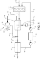
- Figure 1 shows, in a schematic view, an embodiment of the invention.
- the schematic system shown in figure 1 is intended to represent a system arranged on a vehicle where the engine is arranged for propulsion of the vehicle.
- the vehicle itself is not shown or indicated in figure 1 .
- the vehicle comprises an internal combustion engine 1 in this example provided with four combustion chambers/cylinders 2 and an exhaust duct 3.
- the engine is arranged for propulsion of the vehicle.
- Intake air to the engine 1 is indicated by arrow 18.
- Fuel is of course also introduced into the combustion chambers 2.
- the vehicle is provided with a system for recovering waste heat of the internal combustion engine 1.
- the waste heat recovery system is configured to use water as working fluid and comprises: a first heat exchanger 4 configured to evaporate the working fluid/water by transferring heat from exhaust gas originating from the engine 1; an expander unit 5 configured to expand the working fluid/water in a steam expander part 5a that has been evaporated in the first heat exchanger 4 and produce a power output in a power output part 5b.
- the power output 5b may be connected to an electric generator (not shown) for production of electricity that for instance may be used for charging a battery in a hybrid vehicle.
- a passage 11 is provided for transfer of working fluid/water from the first heat exchanger 4 to the expander unit 5.
- the waste heat recovery system further comprises a second heat exchanger 6 configured to condense the working fluid/water and a plurality of pumps 7, 8, 9 for feeding the condensed working fluid/water to the first heat exchanger 4.
- a working fluid/water passage 12 is arranged between the expander unit 5 and the exhaust duct 3 so as to direct the expanded working fluid/water into the exhaust duct 3 at a point or zone 13.
- the second heat exchanger 6 is arranged in association with the exhaust duct 3, in this case as close as possible to the tailpipe of the exhaust duct 3, and it is configured to condense water present in the exhaust gas.
- the first heat exchanger 4 is placed as close as possible to the engine 1 to utilize the heat of the exhaust gas before it is cooled.
- the second heat exchanger 6 (the condenser) is placed as far away from the engine 1 to utilize that the exhaust gas has had at least some time to cool.
- the temperature of the exhaust gas may be around 800°C when entering the first heat exchanger 4 and around 100°C when entering the second heat exchanger 6.
- the second heat exchanger 6 is positioned downstream the point 13 of the exhaust duct 3 at which the expanded working fluid/water is directed into the exhaust gas. Thereby the working fluid/water discharged into the exhaust duct 3 can be condensed in the second heat exchanger.
- the flows through the first and second heat exchangers 4, 6 are indicated by dashed lines.
- the embodiment in figure 1 further comprises a system for introducing water directly or indirectly into the combustion chamber 2 of the internal combustion engine 1, i.e. the water may e.g. be introduced into the intake air 18 before the air enters the combustion chambers 2.
- the vehicle comprises a water distribution system configured to distribute the water condensed in the second heat exchanger 6 between the first heat exchanger 4 and the combustion chamber 2.
- This exemplified water distribution system includes: a condensate pump 7 for feeding water from the condenser 6 to a water tank 10 via a first conduit 14; a low pressure pump (e.g. around 10 bar) 8 for feeding water from the tank 10 towards branch 17 and further towards second and third conduits 15, 16 leading towards the first heat exchanger 4 and the engine 1, respectively; and a high pressure pump (e.g. around 70 bar) 9 for feeding water to the first heat exchanger 4 and further to the expander unit 5 in the waste heat recovery system.
- a condensate pump 7 for feeding water from the condenser 6 to a water tank 10 via a first conduit 14
- a low pressure pump (e.g. around 10 bar) 8 for feeding water from the tank 10 towards branch 17 and further towards second and third conduits 15, 16 leading towards the first heat exchanger 4 and the engine 1, respectively
- a water filter (not shown) may be arranged for cleaning of the water, e.g. between the condensate pump 7 and the tank 10.
- the temperature of the water may be around 50°C (10 bar) after the low pressure pump 8 and around 500°C (70 bar) after having been heated by the exhaust gas in the first heat exchanger 4.
- the water/steam exiting the expander unit 5, or rather exiting the steam expander part 5a may have a temperature of around 150°C and a pressure of around 2 bar.
- the water tank 10 forms a common water tank for both the waste heat recovery system and the system for introducing water directly or indirectly into the combustion chamber 2.
- An advantage of the system described above compared to conventional systems for introducing water directly or indirectly into the combustion chamber 2, which include a separate tank, is that the tank of the system described here is automatically refilled.
- the water distribution system may be arranged in a different way, i.e. the conduits, pumps etc.
- the water/steam passage 12 may alternatively end somewhere along the first heat exchanger 4, i.e. the discharge point or zone 13 need not necessarily be located downstream of the first heat exchanger 4 but may be located somewhere along the first heat exchanger 4. It may be an advantage to locate the discharge point 13 for the low-pressure steam into the exhaust duct 3 somewhere in the middle of the first heat exchanger 4 to utilize remaining enthalpy in the steam, i.e. recuperation, to further increase the efficiency.
- a first portion of the steam may be discharged somewhere along the first heat exchanger 4 and a second portion of the steam may be discharged downstream of the first heat exchanger 4.
Landscapes
- Engineering & Computer Science (AREA)
- Chemical & Material Sciences (AREA)
- Combustion & Propulsion (AREA)
- Mechanical Engineering (AREA)
- General Engineering & Computer Science (AREA)
- Engine Equipment That Uses Special Cycles (AREA)
Abstract
Description
- This invention relates to a vehicle comprising an internal combustion engine and a system for recovering waste heat of the engine according to the preamble of claim 1.
- In order to increase the energy efficiency of internal combustion engines used for powering of vehicles it is known to utilize the waste heat of the engine using a Rankine system where a recirculating working fluid such as ethanol in an evaporation step takes up heat from the exhaust gas or the cooling water of the engine and returns the energy/power to the engine via e.g. an expander turbine connected to a generator. A system of this type also includes a condenser and a pump for recirculating the fluid. An example of such a system is disclosed in
US2015/0176482 . - Another example of a Rankine system is disclosed in
US2013/0333381 where the Rankine system is combined with a system for injecting water into the intake manifold or directly into the combustion chambers of the engine. Such water injection systems are well known as such. (The purpose is to lower the combustion temperature, reduce the production of NOx, and reduce problems related to engine knock.) InUS2013/0333381 the two systems are combined via a shared dual-mode heat exchanger that includes an evaporator for vaporizing the working fluid of the Rankine cycle loop and a condenser for converting to water the water vapour of the exhaust gas for the water injection system. It appears that the systems ofUS2013/0333381 are intended to operate one at a time, either in evaporation mode where the Rankine system is in operation or in a condensation mode where the water injection system is in operation. The main purpose ofUS2013/0333381 is to reduce the space required compared to the use of two separate systems. - A general problem related to Rankine systems of the type discussed here is the safety issue, i.e. the risks associated with pressurizing a flammable fluid like ethanol or acetone in a closed Rankine system (leakage, fire, explosions, etc.). This leads in turn to increased costs for special components, special materials, etc. that reduce the leakage risk (both leakage of working fluid out from the system and leakage of air (oxygen) into the system).
-
US2013/0333381 unintentionally addresses this safety issue by mentioning water as an example of working fluid for the Rankine loop. For thermodynamic reasons it is, however, generally preferred to use a fluid that evaporates at a lower temperature than water in a Rankine loop in this type of application. Moreover, water freezes at a higher temperature than e.g. ethanol and it is difficult to make a closed loop freeze-safe. Besides these potential problems ofUS2013/0333381 , and besides that the Rankine cycle and the water injection system ofUS2013/0333381 cannot operate simultaneously,US2013/0333381 is associated with a further drawback in that the dual-mode heat exchanger has its defined location at the exhaust duct, which means that both evaporation of the Rankine loop working fluid/water and condensation of water in the exhaust gas is carried out at the same (exhaust gas) temperature. It would normally be more efficient to evaporate the Rankine working fluid closer to the engine where the exhaust gas temperature is higher and to condensate water in the exhaust gas further away from the engine where the exhaust gas temperature is lower. - There is thus a need for a waste heat recovery system for vehicles that has a high efficiency and that has a higher safety and lower cost compared to a Rankine cycle as disclosed in e.g.
US2015/0176482 . As toUS2013/0333381 there is also room for improvements with regard to a combined system for waste heat recovery and water injection. - The invention concerns a vehicle comprising an internal combustion engine comprising a combustion chamber and an exhaust duct, and a system for recovering waste heat of the internal combustion engine, wherein the waste heat recovery system comprises: i) a first heat exchanger configured to evaporate a working fluid by transferring heat from a heated medium originating from the engine; ii) an expander unit configured to expand the working fluid that has been evaporated in the first heat exchanger and produce a power output; iii) a second heat exchanger configured to condense the working fluid; and iv) at least one pump for feeding the condensed working fluid to the first heat exchanger.
- The invention is characterized in that the waste heat recovery system is configured to use water as working fluid, wherein a working fluid/water passage is arranged between the expander unit and the exhaust duct so as to direct the expanded working fluid/water into the exhaust duct, wherein the second heat exchanger is arranged in association with the exhaust duct and being configured to condense water present in the exhaust gas, and wherein the second heat exchanger is positioned at or downstream a point or zone of the exhaust duct at which the expanded working fluid/water is directed into the exhaust gas.
- The inventive waste heat recovery system is thus an open Rankine-type system using water as the working fluid where the expanded steam leaving the expander unit is fed out to the exhaust duct. The second heat expander, i.e. the condenser, is arranged at the exhaust duct at or downstream of the feeding point of the expanded steam to allow condensation of the water/steam that has passed the first heat exchanger and the expander (as well as condensation of water resulting from the combustion in the engine). Condensed water can thus be re-introduced into the first heat exchanger, expand in the expander unit, and be directed again into the exhaust duct.
- This solution has several advantages: Since the waste heat recovery system makes use of water and is open to the surroundings downstream the expander unit (because the exhaust duct is open to the surroundings) the main safety issues of conventional closed loop Rankine systems are taken care of, i.e. the risks associated with pressurizing a flammable fluid like ethanol in a closed system (leakage, fire, explosions, etc.). The system can also be made up by less expensive components since water is used and since at least parts of the system operates at a low pressure. Further, the inventive system has a built-in safety function in that the pressure can be released to the exhaust duct. Compared to the system disclosed in
US2013/0333381 the invention has the advantage of allowing the first heat exchanger (the evaporator) to be positioned close to engine where the exhaust gas temperature is high and the second heat exchanger (the condenser) to be positioned far away from engine (close to the tailpipe) where the exhaust gas temperature is low. - Besides that the exhaust gas temperature at the second heat exchanger (the condenser) can be lowered due to the larger distance from the engine (compared to e.g.
US2013/0333381 ), the discharge of expanded steam into the exhaust duct cools the exhaust gas further. In addition, the discharge also increases the concentration of water in the exhaust gas (to up to around 15-20%). All together the condensation process can be made very efficient which allows for a compact (small) second heat exchanger (condenser). - In an embodiment of the invention the vehicle further comprises a system for introducing water directly or indirectly into the combustion chamber of the internal combustion engine, wherein the vehicle comprises a water distribution system configured to distribute the water condensed in the second heat exchanger between the first heat exchanger and the combustion chamber.
- Accordingly, also water that is injected into the combustion chamber can be condensed in the second heat expander and be re-introduced into the combustion chamber (or into the first heat exchanger). The concentration of water in the exhaust of this embodiment will be high, which allows for the use of a compact condenser. Condensed water may be stored in a tank. Refilling of the tank, which is required in conventional separate water injection systems, is likely to be unnecessary, or at least be required only rarely, since water is added to the system (i.e. to the exhaust duct) during operation of the engine as a result of the fuel combustion. The water is continuously replaced so the risk of e.g. growth of algae in the tank is eliminated or at least reduced. Such a plentiful supply of water means that more water can be injected into the combustion chamber, which in turn leads to a more efficient operation of the engine.
- Compared to the arrangement disclosed in
US2013/0333381 this embodiment has the advantage that, besides that the evaporator can be placed closer to the engine and the condenser further away from the engine for better efficiency as mentioned above, both the waste heat recovery system and the water injection system can operate simultaneously. - In an embodiment of the invention the at least one pump for feeding the condensed working fluid to the first heat exchanger includes a high pressure pump. Preferably, the high pressure pump is capable of providing the working fluid/water with a pressure of at least 20 bar, preferably at least 30 bar, more preferably at least 40 or 50 bar. A pressure of 70 bar is likely to be a suitable pressure in most applications of the type discussed here. A pressure of above 100 bar is likely to be too high. A too low pressure will not generate a sufficiently high efficiency of the waste heat recovery system and/or may result in difficulties discharging the steam to the exhaust duct.
- In an embodiment of the invention the vehicle comprises a water tank arranged for storage of water condensed in the second heat exchanger.
- In an embodiment of the invention the expander unit comprises a steam expander part and a power output part that is connected to an electric generator for production of electricity or that is mechanically connected to a drivetrain of the internal combustion engine. Expander units are well known as such. For instance, the expander unit may comprise an axial piston expander, a reciprocal piston expander, a turbine, a scroll expander, etc. Since the expander unit is open to the exhaust duct at the downstream side it should preferably be adapted to keep the pressure on the upstream side. Piston expanders are generally suitable for this purpose. A turbine may be provided with an electrically controlled retarder to keep the pressure.
- In an embodiment of the invention the water distribution system comprises water conduits leading from the second heat exchanger to the first heat exchanger and to the engine. One common conduit, that may include a water tank, may be used to transfer the condensed water from the second heat exchanger to a branching point where one conduit leads further to the first heat exchanger and another conduit leads further to the engine (i.e. directly or indirectly to the combustion chamber).
- In an embodiment of the invention the water tank forms a common water tank for both the waste heat recovery system and the system for introducing water directly or indirectly into the combustion chamber.
- In an embodiment of the invention the vehicle comprises a condensate pump configured to pump water from the second heat exchanger to the water tank.
- In an embodiment of the invention the water distribution system comprises a low pressure pump arranged upstream of the water tank, wherein the low pressure pump is configured to pump water towards both the first heat exchanger and the engine. A common conduit can thus be used.
- In an embodiment of the invention the heated medium originating from the engine is exhaust gas. Expanded working fluid/water may be discharged into the exhaust duct even if the heated medium used for evaporation is e.g. a cooling medium or oil originating from the engine.
- In an embodiment of the invention the internal combustion engine is arranged for propulsion of the vehicle.
- In the description of the invention given below reference is made to the following figure, in which:
- Figure 1
- shows, in a schematic view, an embodiment of the invention.
-
Figure 1 shows, in a schematic view, an embodiment of the invention. The schematic system shown infigure 1 is intended to represent a system arranged on a vehicle where the engine is arranged for propulsion of the vehicle. The vehicle itself is not shown or indicated infigure 1 . - The vehicle comprises an internal combustion engine 1 in this example provided with four combustion chambers/
cylinders 2 and anexhaust duct 3. The engine is arranged for propulsion of the vehicle. Intake air to the engine 1 is indicated byarrow 18. Fuel is of course also introduced into thecombustion chambers 2. - The vehicle is provided with a system for recovering waste heat of the internal combustion engine 1. The waste heat recovery system is configured to use water as working fluid and comprises: a
first heat exchanger 4 configured to evaporate the working fluid/water by transferring heat from exhaust gas originating from the engine 1; anexpander unit 5 configured to expand the working fluid/water in asteam expander part 5a that has been evaporated in thefirst heat exchanger 4 and produce a power output in apower output part 5b. Thepower output 5b may be connected to an electric generator (not shown) for production of electricity that for instance may be used for charging a battery in a hybrid vehicle. Apassage 11 is provided for transfer of working fluid/water from thefirst heat exchanger 4 to theexpander unit 5. - The waste heat recovery system further comprises a
second heat exchanger 6 configured to condense the working fluid/water and a plurality ofpumps first heat exchanger 4. - A working fluid/
water passage 12 is arranged between theexpander unit 5 and theexhaust duct 3 so as to direct the expanded working fluid/water into theexhaust duct 3 at a point orzone 13. - The
second heat exchanger 6 is arranged in association with theexhaust duct 3, in this case as close as possible to the tailpipe of theexhaust duct 3, and it is configured to condense water present in the exhaust gas. - The
first heat exchanger 4 is placed as close as possible to the engine 1 to utilize the heat of the exhaust gas before it is cooled. The second heat exchanger 6 (the condenser) is placed as far away from the engine 1 to utilize that the exhaust gas has had at least some time to cool. The temperature of the exhaust gas may be around 800°C when entering thefirst heat exchanger 4 and around 100°C when entering thesecond heat exchanger 6. - The
second heat exchanger 6 is positioned downstream thepoint 13 of theexhaust duct 3 at which the expanded working fluid/water is directed into the exhaust gas. Thereby the working fluid/water discharged into theexhaust duct 3 can be condensed in the second heat exchanger. - The flows through the first and
second heat exchangers - The embodiment in
figure 1 further comprises a system for introducing water directly or indirectly into thecombustion chamber 2 of the internal combustion engine 1, i.e. the water may e.g. be introduced into theintake air 18 before the air enters thecombustion chambers 2. - The vehicle comprises a water distribution system configured to distribute the water condensed in the
second heat exchanger 6 between thefirst heat exchanger 4 and thecombustion chamber 2. This exemplified water distribution system includes: acondensate pump 7 for feeding water from thecondenser 6 to awater tank 10 via afirst conduit 14; a low pressure pump (e.g. around 10 bar) 8 for feeding water from thetank 10 towardsbranch 17 and further towards second andthird conduits first heat exchanger 4 and the engine 1, respectively; and a high pressure pump (e.g. around 70 bar) 9 for feeding water to thefirst heat exchanger 4 and further to theexpander unit 5 in the waste heat recovery system. - A water filter (not shown) may be arranged for cleaning of the water, e.g. between the
condensate pump 7 and thetank 10. - The temperature of the water may be around 50°C (10 bar) after the low pressure pump 8 and around 500°C (70 bar) after having been heated by the exhaust gas in the
first heat exchanger 4. The water/steam exiting theexpander unit 5, or rather exiting thesteam expander part 5a, may have a temperature of around 150°C and a pressure of around 2 bar. - The
water tank 10 forms a common water tank for both the waste heat recovery system and the system for introducing water directly or indirectly into thecombustion chamber 2. - An advantage of the system described above compared to conventional systems for introducing water directly or indirectly into the
combustion chamber 2, which include a separate tank, is that the tank of the system described here is automatically refilled. - The invention is not limited by the embodiments described above but can be modified in various ways within the scope of the claims. For instance, the water distribution system may be arranged in a different way, i.e. the conduits, pumps etc. Further, the water/
steam passage 12 may alternatively end somewhere along thefirst heat exchanger 4, i.e. the discharge point orzone 13 need not necessarily be located downstream of thefirst heat exchanger 4 but may be located somewhere along thefirst heat exchanger 4. It may be an advantage to locate thedischarge point 13 for the low-pressure steam into theexhaust duct 3 somewhere in the middle of thefirst heat exchanger 4 to utilize remaining enthalpy in the steam, i.e. recuperation, to further increase the efficiency. In a variant a first portion of the steam may be discharged somewhere along thefirst heat exchanger 4 and a second portion of the steam may be discharged downstream of thefirst heat exchanger 4.
Claims (12)
- Vehicle comprising- an internal combustion engine (1) comprising a combustion chamber (2) and an exhaust duct (3),- a system for recovering waste heat of the internal combustion engine (1), wherein the waste heat recovery system comprises:characterized ini) a first heat exchanger (4) configured to evaporate a working fluid by transferring heat from a heated medium originating from the engine (1);ii) an expander unit (5) configured to expand the working fluid that has been evaporated in the first heat exchanger (4) and produce a power output;iii) a second heat exchanger (6) configured to condense the working fluid; andiv) at least one pump (7, 8, 9) for feeding the condensed working fluid to the first heat exchanger (4);
that the waste heat recovery system is configured to use water as working fluid,
wherein a working fluid/water passage (12) is arranged between the expander unit (5) and the exhaust duct (3) so as to direct the expanded working fluid/water into the exhaust duct (3),
wherein the second heat exchanger (6) is arranged in association with the exhaust duct (3) and being configured to condense water present in the exhaust gas, and
wherein the second heat exchanger (6) is positioned at or downstream a point or zone (13) of the exhaust duct (3) at which the expanded working fluid/water is directed into the exhaust gas. - Vehicle according to claim 1, wherein the vehicle further comprises:- a system for introducing water directly or indirectly into the combustion chamber (2) of the internal combustion engine (1), wherein the vehicle comprises a water distribution system (7, 8, 9, 10, 14, 15, 16, 17) configured to distribute the water condensed in the second heat exchanger (6) between the first heat exchanger (4) and the combustion chamber (2).
- Vehicle according to claim 1 or 2, wherein the at least one pump for feeding the condensed working fluid to the first heat exchanger includes a high pressure pump (9).
- Vehicle according to claim 3, wherein the high pressure pump (9) is capable of providing the working fluid/water with a pressure of at least 20 bar, preferably at least 30 bar, more preferably at least 40 or 50 bar, most preferably around 70 bar.
- Vehicle according to anyone of the above claims, wherein the vehicle comprises a water tank (10) arranged for storage of water condensed in the second heat exchanger (6).
- Vehicle according to anyone of the above claims, wherein the expander unit (5) comprises a steam expander (5a) and a power output (5b) that is connected to an electric generator for production of electricity or that is mechanically connected to a drivetrain of the internal combustion engine (1).
- Vehicle according to claim 2, wherein the water distribution system (7, 8, 9, 10, 14, 15, 16, 17) comprises water conduits (14, 15, 16) leading from the second heat exchanger (6) to the first heat exchanger (4) and to the engine (1).
- Vehicle according to claims 2 and 5, wherein the water tank (10) forms a common water tank for both the waste heat recovery system and the system for introducing water directly or indirectly into the combustion chamber (2).
- Vehicle according to claim 8, wherein the vehicle comprises a condensate pump (7) configured to pump water from the second heat exchanger (6) to the water tank (10).
- Vehicle according to claim 9, wherein the water distribution system (7, 8, 9, 10, 14, 15, 16, 17) comprises a low pressure pump (8) arranged upstream of the water tank (10), wherein the low pressure pump (8) is configured to pump water towards both the first heat exchanger (4) and the engine (1).
- Vehicle according to anyone of the above claims, wherein the heated medium originating from the engine (1) is exhaust gas.
- Vehicle according to anyone of the above claims, wherein the internal combustion engine (1) is arranged for propulsion of the vehicle.
Priority Applications (3)
| Application Number | Priority Date | Filing Date | Title |
|---|---|---|---|
| EP18165046.6A EP3546709A1 (en) | 2018-03-29 | 2018-03-29 | Vehicle with system for recovering waste heat |
| CN201910220206.8A CN110318852A (en) | 2018-03-29 | 2019-03-22 | Vehicle with the system for recycling waste heat |
| US16/367,707 US20190301310A1 (en) | 2018-03-29 | 2019-03-28 | Vehicle with system for recovering waste heat |
Applications Claiming Priority (1)
| Application Number | Priority Date | Filing Date | Title |
|---|---|---|---|
| EP18165046.6A EP3546709A1 (en) | 2018-03-29 | 2018-03-29 | Vehicle with system for recovering waste heat |
Publications (1)
| Publication Number | Publication Date |
|---|---|
| EP3546709A1 true EP3546709A1 (en) | 2019-10-02 |
Family
ID=61868247
Family Applications (1)
| Application Number | Title | Priority Date | Filing Date |
|---|---|---|---|
| EP18165046.6A Withdrawn EP3546709A1 (en) | 2018-03-29 | 2018-03-29 | Vehicle with system for recovering waste heat |
Country Status (3)
| Country | Link |
|---|---|
| US (1) | US20190301310A1 (en) |
| EP (1) | EP3546709A1 (en) |
| CN (1) | CN110318852A (en) |
Cited By (2)
| Publication number | Priority date | Publication date | Assignee | Title |
|---|---|---|---|---|
| CN114233442A (en) * | 2021-12-24 | 2022-03-25 | 中国北方发动机研究所(天津) | Engine with waste utilization function |
| EP4293208A1 (en) * | 2022-06-13 | 2023-12-20 | Volvo Truck Corporation | An internal combustion engine system |
Families Citing this family (1)
| Publication number | Priority date | Publication date | Assignee | Title |
|---|---|---|---|---|
| EP4023860B1 (en) * | 2021-01-04 | 2023-08-23 | Volvo Car Corporation | Expander system |
Citations (8)
| Publication number | Priority date | Publication date | Assignee | Title |
|---|---|---|---|---|
| JP2001132538A (en) * | 1999-11-04 | 2001-05-15 | Hideo Kawamura | Engine provided with energy recovery device |
| US20030005696A1 (en) * | 2000-10-18 | 2003-01-09 | Wilson Benjamin Raymond | Internal combustion engine energy extraction devices |
| US20120111001A1 (en) * | 2009-07-21 | 2012-05-10 | Renault Trucks | Engine arrangement with an improved exhaust heat recovery arrangement |
| US20120260654A1 (en) * | 2009-10-06 | 2012-10-18 | Thomas Proepper | Driving device |
| US20130333381A1 (en) | 2012-06-18 | 2013-12-19 | IFP Energies Nouvelles | Internal-combustion engine associated witha rankine cycle closed loop and with a circuit for water injection into the engine intake system |
| US20150176482A1 (en) | 2012-07-09 | 2015-06-25 | Sanden Corporation | Device for Utilizing Waste Heat of Engine |
| US20170130612A1 (en) * | 2014-06-26 | 2017-05-11 | Volvo Truck Corporation | System for a heat energy recovery |
| WO2017098251A1 (en) * | 2015-12-11 | 2017-06-15 | Hieta Technologies Limited | Inverted brayton cycle heat engine |
Family Cites Families (5)
| Publication number | Priority date | Publication date | Assignee | Title |
|---|---|---|---|---|
| DE3261410D1 (en) * | 1981-04-03 | 1985-01-17 | Bbc Brown Boveri & Cie | Combined steam and gas turbine power plant |
| DE19939289C1 (en) * | 1999-08-19 | 2000-10-05 | Mak Motoren Gmbh & Co Kg | Exhaust gas mixture system at an internal combustion motor has a vapor heater to take the mixture from the exhaust gas turbine with a boiler and fresh water supply with a final acid-bonding heat exchanger for safer emissions |
| CN201155385Y (en) * | 2007-12-25 | 2008-11-26 | 黄赖熙 | Engine heat energy reclamation device and two-journey engine applying same |
| GB201406803D0 (en) * | 2014-04-15 | 2014-05-28 | Norgren Ltd C A | Vehicle waste heat recovery system |
| DE102015217737A1 (en) * | 2015-09-16 | 2017-03-16 | Robert Bosch Gmbh | Waste heat recovery system with a working fluid circuit |
-
2018
- 2018-03-29 EP EP18165046.6A patent/EP3546709A1/en not_active Withdrawn
-
2019
- 2019-03-22 CN CN201910220206.8A patent/CN110318852A/en active Pending
- 2019-03-28 US US16/367,707 patent/US20190301310A1/en not_active Abandoned
Patent Citations (8)
| Publication number | Priority date | Publication date | Assignee | Title |
|---|---|---|---|---|
| JP2001132538A (en) * | 1999-11-04 | 2001-05-15 | Hideo Kawamura | Engine provided with energy recovery device |
| US20030005696A1 (en) * | 2000-10-18 | 2003-01-09 | Wilson Benjamin Raymond | Internal combustion engine energy extraction devices |
| US20120111001A1 (en) * | 2009-07-21 | 2012-05-10 | Renault Trucks | Engine arrangement with an improved exhaust heat recovery arrangement |
| US20120260654A1 (en) * | 2009-10-06 | 2012-10-18 | Thomas Proepper | Driving device |
| US20130333381A1 (en) | 2012-06-18 | 2013-12-19 | IFP Energies Nouvelles | Internal-combustion engine associated witha rankine cycle closed loop and with a circuit for water injection into the engine intake system |
| US20150176482A1 (en) | 2012-07-09 | 2015-06-25 | Sanden Corporation | Device for Utilizing Waste Heat of Engine |
| US20170130612A1 (en) * | 2014-06-26 | 2017-05-11 | Volvo Truck Corporation | System for a heat energy recovery |
| WO2017098251A1 (en) * | 2015-12-11 | 2017-06-15 | Hieta Technologies Limited | Inverted brayton cycle heat engine |
Cited By (3)
| Publication number | Priority date | Publication date | Assignee | Title |
|---|---|---|---|---|
| CN114233442A (en) * | 2021-12-24 | 2022-03-25 | 中国北方发动机研究所(天津) | Engine with waste utilization function |
| EP4293208A1 (en) * | 2022-06-13 | 2023-12-20 | Volvo Truck Corporation | An internal combustion engine system |
| US11982217B2 (en) | 2022-06-13 | 2024-05-14 | Volvo Truck Corporation | Internal combustion engine system |
Also Published As
| Publication number | Publication date |
|---|---|
| US20190301310A1 (en) | 2019-10-03 |
| CN110318852A (en) | 2019-10-11 |
Similar Documents
| Publication | Publication Date | Title |
|---|---|---|
| DK178133B1 (en) | Large turbocharged diesel engine with energy recovery device | |
| US9046006B2 (en) | Dual cycle rankine waste heat recovery cycle | |
| Teng et al. | A rankine cycle system for recovering waste heat from HD diesel engines-WHR system development | |
| US20190301310A1 (en) | Vehicle with system for recovering waste heat | |
| UA61957C2 (en) | Method for obtaining energy from the exhaust gas of gas turbine, method and system of regeneration of energy of the exhaust gas heat | |
| KR101261861B1 (en) | Brown gas generating system using waste heat collecting device of engine | |
| JPH07174003A (en) | Improving method of whole generation of available energy in energy utilizer and liquid-cooled thermal power engine carrying out improving method | |
| KR102220071B1 (en) | Boiler system | |
| US11300010B2 (en) | Cooling equipment, combined cycle plant comprising same, and cooling method | |
| JP5121892B2 (en) | Large turbocharged diesel engine with energy recovery configuration | |
| CN103003532B (en) | Engine arrangement comprising a heat recovery circuit | |
| EP2895708B1 (en) | System for recovering through an organic rankine cycle (orc) energy from a plurality of heat sources | |
| US20170051634A1 (en) | Vehicle heat recovery system | |
| KR102220076B1 (en) | Boiler system | |
| RU147861U1 (en) | SECONDARY VEHICLE CIRCUIT OF ICE VEHICLE | |
| US10358946B2 (en) | Expansion apparatus for recovering waste heat and waste heat recovery system including the same | |
| US20140075934A1 (en) | Line circuit and method for operating a line circuit for waste-heat utilization of an internal combustion engine | |
| KR102503727B1 (en) | Power plant equipment performing natural gas regasification | |
| GB2086483A (en) | Plant vaporizing a secondary fluid using heat of compression of a primary fluid. | |
| US11920513B2 (en) | Mono-block reciprocating piston composite ICE/ORC power plant | |
| JP2023093168A (en) | Marine power generation system | |
| KR20230096829A (en) | Power generating system for ship | |
| GB2506597A (en) | Exhaust heat flash steam generator | |
| WO2008004861A1 (en) | System for generating mechanical energy based on thermal energy | |
| CZ200531A3 (en) | Thermal circuit with cryogenic pump and gas turbine |
Legal Events
| Date | Code | Title | Description |
|---|---|---|---|
| PUAI | Public reference made under article 153(3) epc to a published international application that has entered the european phase |
Free format text: ORIGINAL CODE: 0009012 |
|
| STAA | Information on the status of an ep patent application or granted ep patent |
Free format text: STATUS: THE APPLICATION HAS BEEN PUBLISHED |
|
| AK | Designated contracting states |
Kind code of ref document: A1 Designated state(s): AL AT BE BG CH CY CZ DE DK EE ES FI FR GB GR HR HU IE IS IT LI LT LU LV MC MK MT NL NO PL PT RO RS SE SI SK SM TR |
|
| AX | Request for extension of the european patent |
Extension state: BA ME |
|
| STAA | Information on the status of an ep patent application or granted ep patent |
Free format text: STATUS: REQUEST FOR EXAMINATION WAS MADE |
|
| 17P | Request for examination filed |
Effective date: 20200402 |
|
| RBV | Designated contracting states (corrected) |
Designated state(s): AL AT BE BG CH CY CZ DE DK EE ES FI FR GB GR HR HU IE IS IT LI LT LU LV MC MK MT NL NO PL PT RO RS SE SI SK SM TR |
|
| STAA | Information on the status of an ep patent application or granted ep patent |
Free format text: STATUS: EXAMINATION IS IN PROGRESS |
|
| 17Q | First examination report despatched |
Effective date: 20210203 |
|
| STAA | Information on the status of an ep patent application or granted ep patent |
Free format text: STATUS: THE APPLICATION IS DEEMED TO BE WITHDRAWN |
|
| 18D | Application deemed to be withdrawn |
Effective date: 20210615 |