EP3546384A1 - Apparatus and method to make a packet - Google Patents
Apparatus and method to make a packet Download PDFInfo
- Publication number
- EP3546384A1 EP3546384A1 EP19165704.8A EP19165704A EP3546384A1 EP 3546384 A1 EP3546384 A1 EP 3546384A1 EP 19165704 A EP19165704 A EP 19165704A EP 3546384 A1 EP3546384 A1 EP 3546384A1
- Authority
- EP
- European Patent Office
- Prior art keywords
- wall
- stamp
- packet
- flap
- feed
- Prior art date
- Legal status (The legal status is an assumption and is not a legal conclusion. Google has not performed a legal analysis and makes no representation as to the accuracy of the status listed.)
- Withdrawn
Links
Images


Classifications
-
- B—PERFORMING OPERATIONS; TRANSPORTING
- B65—CONVEYING; PACKING; STORING; HANDLING THIN OR FILAMENTARY MATERIAL
- B65C—LABELLING OR TAGGING MACHINES, APPARATUS, OR PROCESSES
- B65C1/00—Labelling flat essentially-rigid surfaces
- B65C1/04—Affixing labels, e.g. wrap-around labels, to two or more flat surfaces of a polyhedral article
- B65C1/042—Affixing labels, e.g. wrap-around labels, to two or more flat surfaces of a polyhedral article using two or more applicators, e.g. cooperating rollers or brushes
- B65C1/045—Affixing labels, e.g. wrap-around labels, to two or more flat surfaces of a polyhedral article using two or more applicators, e.g. cooperating rollers or brushes acting one after the other
Definitions
- Embodiments described here concern an apparatus and a method to make a packet, with which, in particular, to apply a label, revenue stamp, or government stamp, hereafter also simply "stamp", on a packet, in particular a packet for smoking articles.
- a packet for smoking articles is generally formed by a box-like body covered by a transparent film of the disposable type, for example made of cellophane, polyethylene, or other similar material, which therefore forms an external wrapping of the packet.
- the external wrapping is normally provided with a tear strip, able to facilitate its removal, normally self-adhesive, which is placed on the external wrapping.
- the packets for smoking articles of the type in question can, for example, be of the rigid type. Furthermore, in relation to the conformation of the lid, these packets can be of the hinged lid type, that is to say, provided with a closing lid hinged on one side of the box-like body of the packet.
- Such packets are generally simple to produce, starting from a conventional blank, that is, from a material in sheet form such as cardboard, paper or suchlike, suitably shaped and worked, and are easy and practical to use, protecting the smoking articles located inside them.
- the packet for smoking articles also comprises a label, a revenue stamp, or a government stamp, positioned between the external wrapping or packaging and the surface of the box-like body, normally for tax reasons.
- the government stamp needs to normally be invalidated and destroyed, for example separated in a definitive way into two parts, the moment the packet of smoking articles is opened, therefore the moment the external wrapping is removed, or the moment the lid is first opened, for example in the case of hinged lid type packets.
- solutions are known that provide to apply the stamp in correspondence with the separation line between the box-like container and the lid, so that it breaks when the latter is first opened.
- the stamp is applied in correspondence with a smaller lateral wall of the packet, as the front larger lateral wall is generally used to show images and wording indicating the harmful effects of smoking, as required by regulations.
- This double operation can therefore entail on the one hand an incorrect alignment and positioning of the stamp, with consequent aesthetic defects in the packet, or production waste that must be re-processed, and on the other hand possible increases in overall production times.
- one purpose of the present invention is to provide an apparatus to make packets which allows to apply a stamp in a simple and precise manner on two consecutive lateral walls, adjacent and transverse to each other, of a packet.
- Another purpose of the present invention is to provide an apparatus which allows to apply the stamp on two consecutive, adjacent and transverse walls, quickly and automatically.
- a further purpose of the present invention is to provide an apparatus which allows to make a packet for smoking articles that is without blemishes.
- Another purpose of the present invention is to perfect a method to make a packet which provides to apply the stamp to consecutive, adjacent and transverse lateral walls of the packet in an efficient, rapid and precise manner.
- the Applicant has devised, tested and embodied the present invention to overcome the shortcomings of the state of the art and to obtain these and other purposes and advantages.
- Embodiments described here concern a stamp application device suitable to apply a stamp on at least two consecutive walls, adjacent and transverse to each other, of a packet.
- the stamp application device is provided with a folding and pressing member with a shaped portion, for example according to a step conformation, mating with the conformation defined by a first wall and a second wall of a packet, consecutive, adjacent and transverse with respect to each other, in order to apply a stamp in a folded condition, against the first wall and the second wall.
- the folding and pressing member is configured to exert a pressure on a first flap of the stamp against the first wall, and simultaneously fold at least a second flap of the stamp, protruding laterally from an edge between the first wall and the second wall adjacent to it, and take it into contact with the second wall.
- the shaped portion comprises a flat surface suitable to press against the first flap of the stamp, and at least a contrast portion which extends in a direction transverse to the flat surface, and suitable to cooperate with the second flap of the stamp and take it into contact with the second wall.
- the flat surface and the contrast portion intersect along a line disposed substantially parallel to the direction of feed of the packets.
- the shaped portion comprises a flat portion provided with the flat surface, and with a tooth protruding transversely with respect to the flat surface in correspondence with a lateral end of the flat portion, and defining the contrast portion.
- the shaped portion comprises a flat portion and two protruding teeth which extend parallel to each other on the opposite sides of the flat portion.
- the stamp application device comprises a ring-type flexible transmission member wound on at least two pulleys, which comprises an external annular surface which defines the folding and pressing member on at least a portion of its annular development, and an internal annular surface suitable to engage with the pulleys.
- the stamp application device comprises a linear thruster device provided at one end of the folding and pressing member.
- Embodiments described here also concern a unit to apply a stamp on a packet, in particular for smoking articles, which comprises a conveying device configured to feed packets in a row in a direction of feed and a stamp application device according to the invention.
- the stamp application unit comprises presser members configured to press at least the second flap of the stamp, folded according to the step conformation, against the second wall to guarantee a stable attachment of the two components.
- the presser members can comprise shaped rollers, cooperating with the folding and pressing member, and/or with contrast members acting on the opposite side of the packet with respect to the direction of feed.
- Embodiments described here also concern an apparatus to make packets provided with a stamp applied on at least two walls consecutive, adjacent and transverse to each other.
- the apparatus comprises a packet feed device configured to feed the packets in succession, one after the other, a stamp feed device, configured to feed one stamp at a time and deposit it on a first wall of the packet, and a stamp application unit according to the invention, configured to press the stamp on the first wall and apply the stamp also on a second wall of the packet, consecutive, adjacent and transverse to the first wall.
- Further embodiments concern a method to apply a stamp on a packet.
- the method provides to:
- the application of the stamp can be performed in a quick, rapid and efficient manner.
- the simultaneous pressing and folding action allows to use the adhesive material provided between the first flap of the stamp and the first wall to also glue the second flap of the stamp to the second wall.
- Embodiments described here concern an apparatus 10 to make packets 20, particularly suitable to apply a stamp 30 on a packet 20.
- the apparatus 10 according to the invention can advantageously be applied to thin or ultra-thin packets 20, for example with lateral thicknesses comprised between 10mm and 15mm, although its use with packets of different sizes is not excluded.
- a packet 20 can be, for example, a packet for smoking articles, such as cigarettes, cigars, cigarillos, or suchlike, comprising a box-like body 21 generally made of cardboard.
- the box-like body 21 comprises a cup-shaped containing body 22, suitable to contain the smoking articles, and provided with an upper access aperture with which a closing lid 23 is associated.
- the smoking articles are disposed in the containing body 22 in organized groups and can be wrapped by an internal packaging sheet, for example made of foil or metallized paper, or wrapped in an internal hermetic wrapping, for example an aluminum-polyethylene polylaminate or suchlike.
- an internal packaging sheet for example made of foil or metallized paper
- an internal hermetic wrapping for example an aluminum-polyethylene polylaminate or suchlike.
- the packet 20 can be of the hinged lid type, that is to say that the lid 23 is hinged and can rotate with respect to the containing body 22 by means of a hinge 24, which can be made directly on the containing body 22, for example by weakening or pre-creasing it.
- the box-like body 21 is defined by a pair of front 25 and rear 26 larger walls, parallel and opposite each other, joined together in correspondence with their longer sides by means of a pair of lateral walls 27, and in correspondence with their shorter sides respectively by an upper wall 28 and by a lower wall 29.
- the packet 20 is provided with a stamp 30, for example a label, a revenue stamp, or a government stamp, which has to be invalidated the moment the packet 20 is first opened, applied astride the zone separating the containing body 22 and the closing cover 23.
- a stamp 30 for example a label, a revenue stamp, or a government stamp, which has to be invalidated the moment the packet 20 is first opened, applied astride the zone separating the containing body 22 and the closing cover 23.
- the stamp 30 extends with a first flap 31 on a first wall of the packet 20, and with at least a second flap 32 on a second wall, consecutive, adjacent and transverse to the first wall, astride a common edge.
- the first flap 31 extends on a lateral wall 27, while the second flap 32 extends on a larger wall 25, 26; in this specific case, on the larger rear wall 26, so as to not cover the drawings and writing generally shown on the larger front wall 25.
- the first flap 31, applied on the lateral wall 27, is bigger than the second flap 32 applied on the larger rear wall 26.
- the first flap 31 can have a width in the transverse direction substantially corresponding to the width of the lateral wall 27, while the second flap 32 can have a width up to 4-6 times smaller.
- the first edge 31 can have a width comprised between about 11 mm and 12 mm, while the second flap 32 can have a width comprised between about 2 mm and about 3 mm.
- the stamp 30 extends with a first flap 31 on a first wall, and with a second flap 32 on a second wall 26 consecutive, adjacent and transverse to the first wall, astride the common edge between the first and the second wall, and with a third flap 33 on a third wall, parallel to the second wall and consecutive and adjacent to the first wall, astride the common edge between the first wall and the third wall.
- Fig. 4 is used to describe an apparatus 10 to make packets 20 according to the invention, comprising a packet feed device 12 configured to feed the box-like bodies 21 in succession, one after the other, a stamp feed device 14, configured to feed one stamp 30 at a time and deposit it on a first wall of the box-like body 21, and a stamp application unit 16 configured to press the stamp 30 on the first wall and apply the stamp 30 also on a second wall of the box-like body 21, consecutive and adjacent to the first wall.
- a packet feed device 12 configured to feed the box-like bodies 21 in succession, one after the other
- a stamp feed device 14 configured to feed one stamp 30 at a time and deposit it on a first wall of the box-like body 21, and a stamp application unit 16 configured to press the stamp 30 on the first wall and apply the stamp 30 also on a second wall of the box-like body 21, consecutive and adjacent to the first wall.
- the apparatus 10 comprises a conveying device 37, for example provided with a strip, a transport belt, a roller way, or suchlike, on which, during use, the packets 20 are fed in a direction of feed D, disposed in a row one behind the other, resting on a lateral wall 27, and with the other parallel lateral wall 27 facing upward.
- a conveying device 37 for example provided with a strip, a transport belt, a roller way, or suchlike, on which, during use, the packets 20 are fed in a direction of feed D, disposed in a row one behind the other, resting on a lateral wall 27, and with the other parallel lateral wall 27 facing upward.
- the conveying device 37 is configured to feed the packets 20 continuously.
- the conveying device 37 is configured to feed the packets 20 stepwise.
- the conveying device 37 cooperates with guide elements 34 disposed parallel to each other on opposite sides of the conveying device 37, and configured to keep the packets 20 aligned in the direction of feed D, preventing their possible movements in a direction transverse thereto.
- the guide elements 34 can comprise a fixed guide wall 35, disposed longitudinally along one side of the conveying device 37, and configured to define a stable reference for the packet 20 so as to allow a precise positioning of the stamp 30 thereon.
- the guide elements 34 can also comprise mobile contrast elements 36 disposed parallel to each other on the opposite side of the guide wall 35 and configured to exert a thrust on the box-like body 21 in transit in a direction transverse to the direction of feed D, keeping it adjacent to the guide wall 35.
- the stamp feed device 14 comprises at least a positioning member 38 configured to position a stamp 30 resting on a first wall of the box-like body 21, in the example case a lateral wall 27.
- the stamp feed device 14 can comprise a wheel, or rotating disk 39, on whose periphery a plurality of positioning members 38 are mounted, equally distanced from one another.
- the positioning members 38 can be defined by suctioning sectors connected to respective suction means.
- Each positioning member 38 can be configured to hold the stamp 30 during the rotation of the wheel, or rotating disk 39, by suction and apply it on the packet 20 when it is in a position tangent to the latter.
- the positioning member 38 is configured to position the stamp 30 with its longitudinal axis of development aligned in the direction of feed D.
- the stamp 30 is positioned with the first flap 31 resting on the lateral wall 27 of the packet 20, while the second flap 32 protrudes laterally with respect to the edge defined between the lateral wall 27 and the larger wall 26.
- the first flap 31 is provided, on the surface facing the lateral wall 27, with an adhesive material suitable to allow its gluing thereon.
- the stamp application unit 16 is located downstream of the stamp feed device 14 and receives a packet 20 with the stamp 30 partly applied thereon, in the example case on the lateral wall 27 facing upward.
- the stamp application unit 16 comprises, or cooperates with, the device 37 conveying the packets 20.
- the stamp application unit 16 comprises a stamp application device 18, configured to apply the stamp 30 on at least two consecutive, adjacent and transverse walls of a packet 20.
- the stamp application device 18 comprises a folding and pressing member 40 having a shaped portion 40a, mating with the conformation defined by the lateral wall 27 and by at least one larger wall 25 or 26 of the packet 20.
- the shaped portion 40a has a step conformation.
- the folding and pressing member 40 is configured to apply the stamp 30 in a folded condition, adapted to the step conformation, against the first wall and the at least one second wall, in the example case against the lateral wall 27 and the larger rear wall 26.
- the folding and pressing member 40 is configured to exert a pressure on the first flap 31 of the stamp 30 against the first wall, that is, the lateral wall 27, and at the same time to fold the second protruding flap 32 taking it into contact with the second wall, that is, the larger rear wall 26.
- the folding and pressing member 40 is configured to simultaneously exert a pressing action on the first flap 31 and a folding action on the second flap 32.
- the stamp application device 18, by means of the folding and pressing member 40, is configured to press and fold the stamps 30 on the respective packets 20 as they are fed in the direction of feed D.
- the step-shaped portion 40a comprises a flat surface 41 suitable to press the first flap 31 of the stamp 30 against the lateral wall 27, and at least a contrast portion 42 which extends in a direction transverse to the flat surface 41, and suitable to interfere with the second flap 32 of the stamp 30 and take it into contact with the larger rear wall 26.
- the contrast portion 42 extends in a direction substantially orthogonal to the flat surface 41.
- the flat surface 41 and the contrast portion 42 intersect along a line disposed substantially parallel to the direction of feed D.
- the step-shaped portion 40a has an L-shaped section defined by a flat portion 43 provided with the flat surface 41 and by a tooth 44, protruding transversely with respect to the first surface 41 in correspondence with a lateral end of the flat portion 43 and defining the contrast portion 42.
- the step-shaped portion 40a can comprise two protruding teeth 44a, 44b that extend parallel with respect to each other on opposite sides of the flat portion 43. According to these embodiments, it can be provided to apply the stamp 30 on the box-like body 21 with a first flap 31 disposed on the lateral wall 27 and with a second flap 32 and a third flap 33 protruding laterally with respect to the edges defined respectively between the lateral wall 27 and the larger front 25 and rear 26 walls.
- the step-shaped portion 40a can have a "C" or "U”-shaped shape, in which the protruding teeth 44a, 44b each define a contrast portion 42 suitable to act on one of the protruding portions 32, 33, so as to be able to simultaneously make the fold of the two protruding portions 32, 33.
- the protruding teeth 44a, 44b can have the same or different sizes, according to need.
- the presser element 40 acts on the stamp 30 partly applied to the packet 20 in a direction substantially orthogonal to the direction of feed D. In this way, while the flat portion 43 acts with the flat surface 41 on the first flap 31 of the stamp 30, pressing it against the lateral wall 27, the protruding tooth 44 acts on the second flap 32.
- the pressure exerted by the flat portion 43 on the first flap 31 of the stamp 30 partly releases the excess adhesive material present between it and the lateral wall 27, which can therefore be advantageously used to glue the second flap 32 to the larger rear wall 26.
- the stamp application device 18 comprises a flexible transmission member 46 in a closed ring, for example a belt, or a strip, provided with the folding and pressing member 40.
- the flexible transmission member 46 is wound on at least two pulleys 48, 49 with axes of rotation X, X' parallel to each other, of which at least a first transmission pulley 48, connected to a drive member 50 suitable to make it rotate, and at least a second idle pulley 49, which transfer the motion to the flexible member 46.
- the axes of rotation X, X' are orthogonal to the direction of feed D.
- the flexible transmission member 46 can consist of a single annular element, formed by portions 146, 147, 148 in a single body, and having an L-shaped cross-section ( fig. 5a ), or C-shaped or U-shaped ( fig. 5b ).
- the flexible transmission member 46 is, in fact, monolithic and, in particular, is provided with a first portion 146 having a smaller thickness S1, defining the flat portion 43, and at least a second portion 147 having a greater thickness S2, located laterally to the first portion 146 with smaller thickness, and defining the protruding tooth 44.
- the single annular element can comprise a third portion 148 having a thickness S3 greater than the smaller thickness S1, located laterally to the first portion 146 and defining a second protruding tooth 44.
- the second portion 147 and the third portion 148 can have the same or different thicknesses.
- the flexible transmission member 46 can be formed by two or more separate and suitably connected annular elements.
- the flexible transmission member 46 can comprise two ( fig. 5c ) or three ( fig. 5d ) annular elements 246, 247, 248, belt or strip-type, distinct and adjacent to each other.
- the flexible transmission member 46 can for example comprise a first annular element 246 having a smaller thickness S1, which defines the flat portion 43 and at least a second annular element 247, located beside the first annular element 246, and having a thickness S2 greater than the latter, which defines the at least one tooth 44.
- the first annular element 246 with a smaller thickness S 1 is disposed between the second 247 and the third 248 annular elements having greater thicknesses S2, S3.
- the second 247 and the third 248 annular elements can have the same greater thickness, or thicknesses S2, S3 different from one another, both greater than the smaller thickness S1.
- a flexible transmission member 46 consisting of several distinct annular elements 246, 247, 248, it can be provided that they are engaged on the same pulleys 48, 49, or on different pulleys located adjacent to each other, providing suitable reciprocal coupling and alignment members 154.
- the flexible transmission member 46 comprises an external annular surface 46a provided with the folding and pressing member 40, with the step-shaped portion 40a, along its entire annular development, and an internal annular surface 46b suitable to engage with the pulleys 48, 49.
- the flexible transmission member 46 comprises an active branch 47, suitable to cooperate with the packets 20 provided with respective stamps 30 which advance in the direction of feed D.
- the active branch 47 can extend from an entry zone in which the flexible transmission member 46 comes into contact with the packet 20 and/or the stamp 30, and an exit zone in which the flexible transmission member 46 separates from the packet 20.
- the flat portion 43 of the folding and pressing member 40 goes into contact with the first flap 31 of the stamp 30 and upsets it against the lateral wall 27, while the protruding tooth 44 goes into contact with the second flap 32 and folds it against the larger wall 26.
- the active branch 47 is disposed in such a way that the flat surface 41 of the folding and pressing member 40 is disposed substantially parallel to a lying plane P of the lateral walls 27 of the packets 20 provided with the first flap 31 of the stamp 30.
- the transmission pulley 48 is made to rotate in the direction indicated by the arrows F in fig. 1 , so as to move the active branch 47 of the flexible transmission member 46 in a direction concordant with the direction of feed D.
- a flexible transmission member 46 consisting of several distinct annular elements 246, 247, 248, they can be made to rotate in the same direction and with speeds equal to each other.
- the flexible transmission member 46 and the conveying device 37 move in continuous motion with substantially equal and concordant speeds at least in correspondence with the active branch 47.
- the pulleys 48, 49 and the flexible member 46 are provided with coordinated hollows and protrusions made on the respective contact surfaces to allow mutual engagement.
- the internal annular surface 46b can have grooves and transverse protrusions 52 suitable to couple with teeth 53 present on the external lateral surfaces of the pulleys 48, 49.
- the flexible transmission member 46 can have a protuberance 54, rib, or ridge that extends toward the inside of the internal annular surface 46b, suitable to be inserted in a respective groove 55 which develops along the external surface of each pulley 48, 49.
- the flexible transmission member 46 is always correctly centered with respect to the pulleys 48, 49 and, consequently, the folding and pressing member 40 keeps at all times a stable and precise alignment with respect to the direction of feed D.
- a transmission pulley 48 and an idle pulley 49 are present, positioned with the respective external surfaces tangent to a common plane parallel to the lying plane P of the lateral walls 27 provided with the first flap 31 of the stamp 30.
- the transmission pulley 48 has a diameter equal to about 2-3 times the diameter of the idle pulley 49.
- the transmission pulley 48 is located downstream of the idle pulley 49 in the direction of feed D, so as to facilitate the introduction of the box-like body 21 in transit below the active branch 47.
- the angle defined between the lying plane P and the plane tangent to the idle pulley 49 in correspondence with the end of the active branch 47 is in fact greater for the idle pulley 49 than the angle that would be defined for the transmission pulley 48.
- the stamp application unit 16 comprises presser members 58 configured to press the second flap 32 of the stamp 30, previously folded by the stamp application device 18 so as to guarantee a stable gluing.
- the presser members 58 are configured to press laterally on the second flap 32 so as to glue and stabilize the gluing of the second flap 32 on the larger rear wall 26, thanks to the adhesive material originating from the first flap 31.
- the presser members 58 comprise at least a shaped roller 60 disposed on the side of the folding and pressing member 40, for example on the side of the flexible transmission member 46 downstream of the entry zone of the active branch 47.
- the shaped roller 60 has an upper cylindrical portion 61 suitable to act laterally against the tooth 44 of the folding and pressing member 40, and a lower cylindrical portion 62 suitable to act directly in contact with the second flap 32 of the stamp 30.
- the lower cylindrical portion 62 has a greater radius with respect to the radius of the upper cylindrical portion 61; in particular, the difference between the two radiuses corresponds substantially to the transverse size of the protruding tooth 44.
- the lower cylindrical portion 62 extends partly below the folding and pressing member 40 until it goes into contact with the second flap 32 of the stamp 30 and/or the larger rear wall 26 of the packet 20.
- the heights of the respective upper 61 and lower 62 cylindrical portions are sized according to the height of the tooth 44, so that the lower cylindrical portion 62 is located at a minimum distance from its end.
- this minimum distance is less than 0.2 mm, or even less than 0.1 mm.
- two shaped rollers 60 are present, located adjacent to each other in the direction of feed D, so as to keep the second flap 32 pressed against the larger rear wall 26 for a longer segment, and thus guarantee a better adhesion of the stamp 30.
- the presser elements 58 comprise at least a contrast roller 64 disposed on the opposite side of the packet 20 with respect to the shaped roller 60 and configured to exert a contrast action on the packet 20 in the opposite direction to that exerted by the shaped roller 60 with respect to the direction of feed D.
- a contrast roller 64 can be provided for each shaped roller 60.
- shaped rollers 60 can be provided, each disposed on one side of the conveying device 37 ( fig. 6 ) and configured to act in opposite directions to each other.
- the upper cylindrical portions 61 act in opposite lateral directions on the external surface of a respective tooth 44a, 44b, while the lower cylindrical portions 62 act directly on one of the larger front 25 and rear 26 walls of a packet 20.
- the presser members 58 and/or the contrast members 64 can be disposed downstream of the folding and pressing member 40.
- the stamp application unit 16 comprises an internal contrast element 66 configured to exert a contrast action on the flexible transmission member 46 in order to keep the folding and pressing member 40 in contact with the stamp 30 and the packet 20.
- the internal contrast element 66 can be disposed inside the ring defined by the flexible transmission member 46 and be configured to act thereon in the intermediate space between the two pulleys 48, 49 so as to keep the active branch 47 in abutment against the first flap 31 of the stamp 30 and the lateral wall 27 of the packet 20 in transit below it.
- the stamp application device 16 also comprises an external contrast element 68, configured to facilitate the separation of the flexible transmission member 46 from the packet 20.
- the external contrast element 68 is disposed outside the flexible transmission member 46, in correspondence with the exit zone of the active branch 47.
- the external contrast element 68 comprises a lower surface 69 which extends parallel to the lying plane P of the lateral walls 27, and is suitable to keep the packet 20 in transit in contact with the conveying device 37, preventing it from rearing up because of a drawing action generated by the rotation of the flexible transmission member 46.
- Embodiments described here also concern a method to apply a stamp 30 on a packet 20 which provides to:
- the method provides to simultaneously perform the actions of pressing the first flap 31 and of folding the second flap 32.
- the method provides to carry out the pressing and folding actions of the respective first flap 31 and second flap 32 of the stamp 30 while the packet 20 is fed on a conveying device 37, by means of a flexible transmission member 46 wound on two pulleys 48, 49 which make it rotate, provided with the L, C or U-shaped folding and pressing member 40 on its peripheral development.
- the application device 18 can comprise a linear thruster device 70 provided at one end of the folding and pressing member 40.
- the linear thruster device 70 can comprise a linear actuator, for example of the piston 72/cylinder 73 type, with the folding and pressing member 40 mounted at the end of the piston 72.
- the linear thruster device 70 is configured to move linearly forward and backward in a drive direction F.
- the drive direction F is orthogonal to the direction of feed D with respect to a vertical plane.
- the folding and pressing member 40 can have an L-shaped shaped portion 40a, as shown with the solid lines in fig. 7 , or C-shaped or U-shaped, also providing a second tooth 44, shown with dotted lines in the drawing.
- the conveying device 37 feeds the packets 20 stepwise in the direction of feed D until they are disposed, already provided with the stamp 30 partly applied thereon, below the linear thruster device 70.
- the linear thruster device 70 moves the folding and pressing member 40 in the drive direction F, so as to press the first flap 31 against the first wall 27 and fold the second flap 32 against the second wall 26.
- the linear thruster device 70 is a tracking device to track the packet 20 during its feed in the direction D, keeping the folding and pressing member 40 in contact with the packet 20 in the direction of feed D.
Landscapes
- Making Paper Articles (AREA)
- Auxiliary Devices For And Details Of Packaging Control (AREA)
Abstract
Description
- Embodiments described here concern an apparatus and a method to make a packet, with which, in particular, to apply a label, revenue stamp, or government stamp, hereafter also simply "stamp", on a packet, in particular a packet for smoking articles.
- It is known that a packet for smoking articles, for example cigarettes, is generally formed by a box-like body covered by a transparent film of the disposable type, for example made of cellophane, polyethylene, or other similar material, which therefore forms an external wrapping of the packet. The external wrapping is normally provided with a tear strip, able to facilitate its removal, normally self-adhesive, which is placed on the external wrapping.
- The packets for smoking articles of the type in question can, for example, be of the rigid type. Furthermore, in relation to the conformation of the lid, these packets can be of the hinged lid type, that is to say, provided with a closing lid hinged on one side of the box-like body of the packet. Such packets are generally simple to produce, starting from a conventional blank, that is, from a material in sheet form such as cardboard, paper or suchlike, suitably shaped and worked, and are easy and practical to use, protecting the smoking articles located inside them.
- In addition to the cardboard box-like body, or suchlike, and to the external wrapping, the packet for smoking articles also comprises a label, a revenue stamp, or a government stamp, positioned between the external wrapping or packaging and the surface of the box-like body, normally for tax reasons.
- The government stamp needs to normally be invalidated and destroyed, for example separated in a definitive way into two parts, the moment the packet of smoking articles is opened, therefore the moment the external wrapping is removed, or the moment the lid is first opened, for example in the case of hinged lid type packets.
- Different systems and methodologies to apply the government stamp on the packet of cigarettes are known, so as to allow its invalidation at the first opening.
- For example, solutions are known that provide to apply the stamp in correspondence with the separation line between the box-like container and the lid, so that it breaks when the latter is first opened. In particular, the stamp is applied in correspondence with a smaller lateral wall of the packet, as the front larger lateral wall is generally used to show images and wording indicating the harmful effects of smoking, as required by regulations.
- One disadvantage of this known solution is that it is difficult to apply in the case of packets with a reduced thickness, for example for very thin, or "superslim" cigarettes, or in any case when the sizes of the stamp exceed those of a smaller lateral wall of the packet.
- In this case, in fact, it is necessary to apply a first part of the stamp on a smaller lateral wall, and a second part on a larger lateral wall, consecutive, adjacent and transverse, typically orthogonal, to it.
- This double operation can therefore entail on the one hand an incorrect alignment and positioning of the stamp, with consequent aesthetic defects in the packet, or production waste that must be re-processed, and on the other hand possible increases in overall production times.
- Other solutions known in the state of the art are described in prior art documents
GB-A-2.157.260 EP-A1-2.279.955 andGB-A-533.616 - There is therefore the need to provide an apparatus and a method to make a packet, in particular for smoking articles, which can overcome at least one of the disadvantages of the state of the art.
- In particular, one purpose of the present invention is to provide an apparatus to make packets which allows to apply a stamp in a simple and precise manner on two consecutive lateral walls, adjacent and transverse to each other, of a packet.
- Another purpose of the present invention is to provide an apparatus which allows to apply the stamp on two consecutive, adjacent and transverse walls, quickly and automatically.
- A further purpose of the present invention is to provide an apparatus which allows to make a packet for smoking articles that is without blemishes.
- Furthermore, another purpose of the present invention is to perfect a method to make a packet which provides to apply the stamp to consecutive, adjacent and transverse lateral walls of the packet in an efficient, rapid and precise manner.
- The Applicant has devised, tested and embodied the present invention to overcome the shortcomings of the state of the art and to obtain these and other purposes and advantages.
- The present invention is set forth and characterized in the independent claims, while the dependent claims describe other characteristics of the invention or variants to the main inventive idea.
- Embodiments described here concern a stamp application device suitable to apply a stamp on at least two consecutive walls, adjacent and transverse to each other, of a packet.
- According to some embodiments, the stamp application device is provided with a folding and pressing member with a shaped portion, for example according to a step conformation, mating with the conformation defined by a first wall and a second wall of a packet, consecutive, adjacent and transverse with respect to each other, in order to apply a stamp in a folded condition, against the first wall and the second wall.
- According to some embodiments, the folding and pressing member is configured to exert a pressure on a first flap of the stamp against the first wall, and simultaneously fold at least a second flap of the stamp, protruding laterally from an edge between the first wall and the second wall adjacent to it, and take it into contact with the second wall.
- According to some embodiments, the shaped portion comprises a flat surface suitable to press against the first flap of the stamp, and at least a contrast portion which extends in a direction transverse to the flat surface, and suitable to cooperate with the second flap of the stamp and take it into contact with the second wall.
- According to some embodiments, the flat surface and the contrast portion intersect along a line disposed substantially parallel to the direction of feed of the packets.
- According to some embodiments, the shaped portion comprises a flat portion provided with the flat surface, and with a tooth protruding transversely with respect to the flat surface in correspondence with a lateral end of the flat portion, and defining the contrast portion.
- According to possible variant embodiments, the shaped portion comprises a flat portion and two protruding teeth which extend parallel to each other on the opposite sides of the flat portion.
- According to further embodiments, the stamp application device comprises a ring-type flexible transmission member wound on at least two pulleys, which comprises an external annular surface which defines the folding and pressing member on at least a portion of its annular development, and an internal annular surface suitable to engage with the pulleys. This solution allows to upset and fold the stamp on the packet in a very effective manner, exploiting the introduction zone of the packet below the flexible transmission member to define the fold of the second flap, and possibly of the third flap, and then exploiting an active branch of the flexible transmission member, below which the packet transits, to keep a continuous pressure on the stamp so as to guarantee its secure attachment on the packet.
- According to variant embodiments, the stamp application device comprises a linear thruster device provided at one end of the folding and pressing member.
- Embodiments described here also concern a unit to apply a stamp on a packet, in particular for smoking articles, which comprises a conveying device configured to feed packets in a row in a direction of feed and a stamp application device according to the invention.
- According to further embodiments, the stamp application unit comprises presser members configured to press at least the second flap of the stamp, folded according to the step conformation, against the second wall to guarantee a stable attachment of the two components.
- According to further embodiments, the presser members can comprise shaped rollers, cooperating with the folding and pressing member, and/or with contrast members acting on the opposite side of the packet with respect to the direction of feed.
- Embodiments described here also concern an apparatus to make packets provided with a stamp applied on at least two walls consecutive, adjacent and transverse to each other. The apparatus comprises a packet feed device configured to feed the packets in succession, one after the other, a stamp feed device, configured to feed one stamp at a time and deposit it on a first wall of the packet, and a stamp application unit according to the invention, configured to press the stamp on the first wall and apply the stamp also on a second wall of the packet, consecutive, adjacent and transverse to the first wall.
- Further embodiments concern a method to apply a stamp on a packet. The method provides to:
- feed in a row, in a direction of feed, packets provided with stamps with a first flap of the stamp applied on a first wall and a second flap of the stamp protruding laterally from a common edge between the first wall and a second wall consecutive, adjacent and transverse to the first wall;
- apply the stamp in a folded condition on the packet, pressing the first flap of the stamp against the first wall and simultaneously folding the at least one second flap astride the edge, taking it into contact against the second wall, in which the edge between the first wall and the second wall is disposed substantially parallel to the direction of feed while the packets are fed in a row.
- As the pressing action of the first flap and the folding action of the second flap occur simultaneously, the application of the stamp can be performed in a quick, rapid and efficient manner.
- Furthermore, the simultaneous pressing and folding action allows to use the adhesive material provided between the first flap of the stamp and the first wall to also glue the second flap of the stamp to the second wall.
- These and other characteristics of the present invention will become apparent from the following description of some embodiments, given as a non-restrictive example with reference to the attached drawings wherein:
-
fig. 1 is a schematic lateral view of a stamp application device according to embodiments described here; -
fig. 2 is a schematic three-dimensional view of a packet according to embodiments described here; -
fig. 3 is a schematic lateral view of a stamp application device according to embodiments described here; -
fig. 4 is a schematic three-dimensional view from one side of an apparatus to make packets according to embodiments described here; -
fig. 5 is a detail of the stamp application unit of the apparatus offig. 4 from the opposite side; -
fig. 5a is an enlarged detail offig. 5 according to embodiments described here; -
fig. 5b is an enlarged detail offig. 5 according to variant embodiments; -
fig. 5c is an enlarged detail offig. 5 according to other variant embodiments; -
fig. 5d is an enlarged detail offig. 5 according to further variant embodiments; -
fig. 6 is a section view of the stamp application unit offig. 2 ; -
fig. 7 is a section view of a variant of a stamp application unit according to further embodiments; -
figs. 8 and 9 are schematic views, respectively a lateral view and a three-dimensional view, of a stamp application unit according to another variant embodiment. - To facilitate comprehension, the same reference numbers have been used, where possible, to identify identical common elements in the drawings. It is understood that elements and characteristics of one embodiment can conveniently be incorporated into other embodiments without further clarifications.
- We will now refer in detail to the various embodiments of the present invention, of which one or more examples are shown in the attached drawings. Each example is supplied by way of illustration of the invention and shall not be understood as a limitation thereof. For example, the characteristics shown or described insomuch as they are part of one embodiment can be adopted on, or in association with, other embodiments to produce another embodiment. It is understood that the present invention shall include all such modifications and variants.
- Embodiments described here concern an apparatus 10 to make
packets 20, particularly suitable to apply astamp 30 on apacket 20. - The apparatus 10 according to the invention can advantageously be applied to thin or
ultra-thin packets 20, for example with lateral thicknesses comprised between 10mm and 15mm, although its use with packets of different sizes is not excluded. - With reference to
fig. 2 , apacket 20 can be, for example, a packet for smoking articles, such as cigarettes, cigars, cigarillos, or suchlike, comprising a box-like body 21 generally made of cardboard. - The box-
like body 21 comprises a cup-shaped containingbody 22, suitable to contain the smoking articles, and provided with an upper access aperture with which a closinglid 23 is associated. - Typically, the smoking articles are disposed in the containing
body 22 in organized groups and can be wrapped by an internal packaging sheet, for example made of foil or metallized paper, or wrapped in an internal hermetic wrapping, for example an aluminum-polyethylene polylaminate or suchlike. - The
packet 20 according to some embodiments described here can be of the hinged lid type, that is to say that thelid 23 is hinged and can rotate with respect to the containingbody 22 by means of ahinge 24, which can be made directly on the containingbody 22, for example by weakening or pre-creasing it. - According to some embodiments, the box-
like body 21 is defined by a pair offront 25 and rear 26 larger walls, parallel and opposite each other, joined together in correspondence with their longer sides by means of a pair oflateral walls 27, and in correspondence with their shorter sides respectively by anupper wall 28 and by alower wall 29. - The
packet 20 is provided with astamp 30, for example a label, a revenue stamp, or a government stamp, which has to be invalidated the moment thepacket 20 is first opened, applied astride the zone separating the containingbody 22 and theclosing cover 23. - According to some embodiments, for example described with reference to
fig. 2 , thestamp 30 extends with afirst flap 31 on a first wall of thepacket 20, and with at least asecond flap 32 on a second wall, consecutive, adjacent and transverse to the first wall, astride a common edge. - For example, according to some embodiments, the
first flap 31 extends on alateral wall 27, while thesecond flap 32 extends on alarger wall rear wall 26, so as to not cover the drawings and writing generally shown on the largerfront wall 25. - According to some embodiments, the
first flap 31, applied on thelateral wall 27, is bigger than thesecond flap 32 applied on the largerrear wall 26. - According to some embodiments, the
first flap 31 can have a width in the transverse direction substantially corresponding to the width of thelateral wall 27, while thesecond flap 32 can have a width up to 4-6 times smaller. - By way of example only, if the
stamp 30 has a transverse size of about 14 mm, and thelateral wall 27 has a width of about 12 mm, thefirst edge 31 can have a width comprised between about 11 mm and 12 mm, while thesecond flap 32 can have a width comprised between about 2 mm and about 3 mm. - According to possible variants, for example described with reference to
fig. 7 , thestamp 30 extends with afirst flap 31 on a first wall, and with asecond flap 32 on asecond wall 26 consecutive, adjacent and transverse to the first wall, astride the common edge between the first and the second wall, and with athird flap 33 on a third wall, parallel to the second wall and consecutive and adjacent to the first wall, astride the common edge between the first wall and the third wall. -
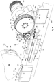
Fig. 4 is used to describe an apparatus 10 to makepackets 20 according to the invention, comprising a packet feed device 12 configured to feed the box-like bodies 21 in succession, one after the other, astamp feed device 14, configured to feed onestamp 30 at a time and deposit it on a first wall of the box-like body 21, and astamp application unit 16 configured to press thestamp 30 on the first wall and apply thestamp 30 also on a second wall of the box-like body 21, consecutive and adjacent to the first wall. - According to some embodiments, for example described with reference to
figs. 3-9 , the apparatus 10 comprises a conveyingdevice 37, for example provided with a strip, a transport belt, a roller way, or suchlike, on which, during use, thepackets 20 are fed in a direction of feed D, disposed in a row one behind the other, resting on alateral wall 27, and with the other parallellateral wall 27 facing upward. - According to some embodiments, the conveying
device 37 is configured to feed thepackets 20 continuously. - According to possible variants, the conveying
device 37 is configured to feed thepackets 20 stepwise. - According to some embodiments, the conveying
device 37 cooperates withguide elements 34 disposed parallel to each other on opposite sides of the conveyingdevice 37, and configured to keep thepackets 20 aligned in the direction of feed D, preventing their possible movements in a direction transverse thereto. - According to possible solutions, the
guide elements 34 can comprise a fixedguide wall 35, disposed longitudinally along one side of the conveyingdevice 37, and configured to define a stable reference for thepacket 20 so as to allow a precise positioning of thestamp 30 thereon. - The
guide elements 34 can also comprisemobile contrast elements 36 disposed parallel to each other on the opposite side of theguide wall 35 and configured to exert a thrust on the box-like body 21 in transit in a direction transverse to the direction of feed D, keeping it adjacent to theguide wall 35. - In this way, a well-defined reference position is defined for the
packet 20 in correspondence with the operating zone of thestamp feed device 14, thus guaranteeing the precise positioning of thestamp 30 on thepacket 20. - According to some embodiments, the
stamp feed device 14 comprises at least a positioningmember 38 configured to position astamp 30 resting on a first wall of the box-like body 21, in the example case alateral wall 27. - According to possible solutions, for example described with reference to
fig. 4 , thestamp feed device 14 can comprise a wheel, orrotating disk 39, on whose periphery a plurality ofpositioning members 38 are mounted, equally distanced from one another. - In
fig. 4 , by way of example only, fourpositioning members 38 are provided offset by 90°, of which only two are visible, but a different number can be provided according to production needs. - According to some embodiments, the
positioning members 38 can be defined by suctioning sectors connected to respective suction means. Each positioningmember 38 can be configured to hold thestamp 30 during the rotation of the wheel, orrotating disk 39, by suction and apply it on thepacket 20 when it is in a position tangent to the latter. - According to some embodiments, the positioning
member 38 is configured to position thestamp 30 with its longitudinal axis of development aligned in the direction of feed D. - According to some embodiments, the
stamp 30 is positioned with thefirst flap 31 resting on thelateral wall 27 of thepacket 20, while thesecond flap 32 protrudes laterally with respect to the edge defined between thelateral wall 27 and thelarger wall 26. - According to some embodiments, the
first flap 31 is provided, on the surface facing thelateral wall 27, with an adhesive material suitable to allow its gluing thereon. - According to some embodiments, the
stamp application unit 16 is located downstream of thestamp feed device 14 and receives apacket 20 with thestamp 30 partly applied thereon, in the example case on thelateral wall 27 facing upward. - According to some embodiments, the
stamp application unit 16 comprises, or cooperates with, thedevice 37 conveying thepackets 20. - According to some embodiments, the
stamp application unit 16 comprises astamp application device 18, configured to apply thestamp 30 on at least two consecutive, adjacent and transverse walls of apacket 20. - According to some embodiments, the
stamp application device 18 comprises a folding and pressingmember 40 having a shapedportion 40a, mating with the conformation defined by thelateral wall 27 and by at least onelarger wall packet 20. In a particular embodiment, the shapedportion 40a has a step conformation. - According to some embodiments, the folding and pressing
member 40 is configured to apply thestamp 30 in a folded condition, adapted to the step conformation, against the first wall and the at least one second wall, in the example case against thelateral wall 27 and the largerrear wall 26. - In particular, the folding and pressing
member 40 is configured to exert a pressure on thefirst flap 31 of thestamp 30 against the first wall, that is, thelateral wall 27, and at the same time to fold the second protrudingflap 32 taking it into contact with the second wall, that is, the largerrear wall 26. - According to possible solutions, the folding and pressing
member 40 is configured to simultaneously exert a pressing action on thefirst flap 31 and a folding action on thesecond flap 32. - According to some embodiments, the
stamp application device 18, by means of the folding and pressingmember 40, is configured to press and fold thestamps 30 on therespective packets 20 as they are fed in the direction of feed D. - According to some embodiments, the step-shaped
portion 40a comprises aflat surface 41 suitable to press thefirst flap 31 of thestamp 30 against thelateral wall 27, and at least acontrast portion 42 which extends in a direction transverse to theflat surface 41, and suitable to interfere with thesecond flap 32 of thestamp 30 and take it into contact with the largerrear wall 26. - According to some embodiments, the
contrast portion 42 extends in a direction substantially orthogonal to theflat surface 41. - According to some embodiments, the
flat surface 41 and thecontrast portion 42 intersect along a line disposed substantially parallel to the direction of feed D. - According to some embodiments, for example described with reference to
fig. 6 or8 , the step-shapedportion 40a has an L-shaped section defined by aflat portion 43 provided with theflat surface 41 and by atooth 44, protruding transversely with respect to thefirst surface 41 in correspondence with a lateral end of theflat portion 43 and defining thecontrast portion 42. - According to possible variants, for example described with reference to
fig. 7 , the step-shapedportion 40a can comprise two protrudingteeth flat portion 43. According to these embodiments, it can be provided to apply thestamp 30 on the box-like body 21 with afirst flap 31 disposed on thelateral wall 27 and with asecond flap 32 and athird flap 33 protruding laterally with respect to the edges defined respectively between thelateral wall 27 and thelarger front 25 and rear 26 walls. - According to this embodiment, the step-shaped
portion 40a can have a "C" or "U"-shaped shape, in which the protrudingteeth contrast portion 42 suitable to act on one of the protrudingportions portions - According to some embodiments, the protruding
teeth - According to some embodiments, the
presser element 40 acts on thestamp 30 partly applied to thepacket 20 in a direction substantially orthogonal to the direction of feed D. In this way, while theflat portion 43 acts with theflat surface 41 on thefirst flap 31 of thestamp 30, pressing it against thelateral wall 27, the protrudingtooth 44 acts on thesecond flap 32. - According to some embodiments, the pressure exerted by the
flat portion 43 on thefirst flap 31 of thestamp 30 partly releases the excess adhesive material present between it and thelateral wall 27, which can therefore be advantageously used to glue thesecond flap 32 to the largerrear wall 26. - According to some embodiments, for example shown with reference to
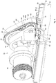
figs. 3-7 , thestamp application device 18 comprises aflexible transmission member 46 in a closed ring, for example a belt, or a strip, provided with the folding and pressingmember 40. - According to some embodiments, the
flexible transmission member 46 is wound on at least twopulleys first transmission pulley 48, connected to adrive member 50 suitable to make it rotate, and at least a secondidle pulley 49, which transfer the motion to theflexible member 46. - According to some embodiments, the axes of rotation X, X' are orthogonal to the direction of feed D.
- According to some embodiments, for example described with reference to
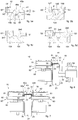
figs. 5a and 5b , theflexible transmission member 46 can consist of a single annular element, formed byportions fig. 5a ), or C-shaped or U-shaped (fig. 5b ). - According to these embodiments, the
flexible transmission member 46 is, in fact, monolithic and, in particular, is provided with afirst portion 146 having a smaller thickness S1, defining theflat portion 43, and at least asecond portion 147 having a greater thickness S2, located laterally to thefirst portion 146 with smaller thickness, and defining the protrudingtooth 44. - In the case of a C-shaped or U-shaped cross-section, on the other hand, the single annular element can comprise a
third portion 148 having a thickness S3 greater than the smaller thickness S1, located laterally to thefirst portion 146 and defining a second protrudingtooth 44. - According to some embodiments, the
second portion 147 and thethird portion 148 can have the same or different thicknesses. - According to other embodiments, for example described with reference to
figs. 5c and 5d , theflexible transmission member 46 can be formed by two or more separate and suitably connected annular elements. For example, in these embodiments theflexible transmission member 46 can comprise two (fig. 5c ) or three (fig. 5d )annular elements - According to these embodiments, the
flexible transmission member 46 can for example comprise a firstannular element 246 having a smaller thickness S1, which defines theflat portion 43 and at least a secondannular element 247, located beside the firstannular element 246, and having a thickness S2 greater than the latter, which defines the at least onetooth 44. - In the case of three
annular elements annular element 246 with asmaller thickness S 1 is disposed between the second 247 and the third 248 annular elements having greater thicknesses S2, S3. - According to some embodiments, the second 247 and the third 248 annular elements can have the same greater thickness, or thicknesses S2, S3 different from one another, both greater than the smaller thickness S1.
- According to some embodiments, in the case of a
flexible transmission member 46 consisting of several distinctannular elements same pulleys alignment members 154. - According to some embodiments, the
flexible transmission member 46 comprises an externalannular surface 46a provided with the folding and pressingmember 40, with the step-shapedportion 40a, along its entire annular development, and an internalannular surface 46b suitable to engage with thepulleys - According to some embodiments, the
flexible transmission member 46 comprises anactive branch 47, suitable to cooperate with thepackets 20 provided withrespective stamps 30 which advance in the direction of feed D. - The
active branch 47, for example, can extend from an entry zone in which theflexible transmission member 46 comes into contact with thepacket 20 and/or thestamp 30, and an exit zone in which theflexible transmission member 46 separates from thepacket 20. - According to some embodiments, in the entry zone the
flat portion 43 of the folding and pressingmember 40 goes into contact with thefirst flap 31 of thestamp 30 and upsets it against thelateral wall 27, while the protrudingtooth 44 goes into contact with thesecond flap 32 and folds it against thelarger wall 26. - According to some embodiments, the
active branch 47 is disposed in such a way that theflat surface 41 of the folding and pressingmember 40 is disposed substantially parallel to a lying plane P of thelateral walls 27 of thepackets 20 provided with thefirst flap 31 of thestamp 30. - According to some embodiments, the
transmission pulley 48 is made to rotate in the direction indicated by the arrows F infig. 1 , so as to move theactive branch 47 of theflexible transmission member 46 in a direction concordant with the direction of feed D. - According to some embodiments, in the case of a
flexible transmission member 46 consisting of several distinctannular elements - According to some embodiments, the
flexible transmission member 46 and the conveyingdevice 37 move in continuous motion with substantially equal and concordant speeds at least in correspondence with theactive branch 47. - According to some embodiments, the
pulleys flexible member 46 are provided with coordinated hollows and protrusions made on the respective contact surfaces to allow mutual engagement. - For example, the internal
annular surface 46b can have grooves andtransverse protrusions 52 suitable to couple withteeth 53 present on the external lateral surfaces of thepulleys - According to further embodiments, the
flexible transmission member 46 can have aprotuberance 54, rib, or ridge that extends toward the inside of the internalannular surface 46b, suitable to be inserted in arespective groove 55 which develops along the external surface of eachpulley - In this way, the
flexible transmission member 46 is always correctly centered with respect to thepulleys member 40 keeps at all times a stable and precise alignment with respect to the direction of feed D. - According to possible solutions, only a
transmission pulley 48 and anidle pulley 49 are present, positioned with the respective external surfaces tangent to a common plane parallel to the lying plane P of thelateral walls 27 provided with thefirst flap 31 of thestamp 30. - According to some embodiments, the
transmission pulley 48 has a diameter equal to about 2-3 times the diameter of theidle pulley 49. - According to possible solutions, the
transmission pulley 48 is located downstream of theidle pulley 49 in the direction of feed D, so as to facilitate the introduction of the box-like body 21 in transit below theactive branch 47. - The angle defined between the lying plane P and the plane tangent to the
idle pulley 49 in correspondence with the end of theactive branch 47 is in fact greater for theidle pulley 49 than the angle that would be defined for thetransmission pulley 48. - According to some embodiments, for example described with reference to
figs. 4-6 , thestamp application unit 16 comprisespresser members 58 configured to press thesecond flap 32 of thestamp 30, previously folded by thestamp application device 18 so as to guarantee a stable gluing. - The
presser members 58 are configured to press laterally on thesecond flap 32 so as to glue and stabilize the gluing of thesecond flap 32 on the largerrear wall 26, thanks to the adhesive material originating from thefirst flap 31. - According to some embodiments, the
presser members 58 comprise at least ashaped roller 60 disposed on the side of the folding and pressingmember 40, for example on the side of theflexible transmission member 46 downstream of the entry zone of theactive branch 47. - According to some embodiments, for example described with reference to
fig. 4 , the shapedroller 60 has an uppercylindrical portion 61 suitable to act laterally against thetooth 44 of the folding and pressingmember 40, and a lowercylindrical portion 62 suitable to act directly in contact with thesecond flap 32 of thestamp 30. - According to these solutions, the lower
cylindrical portion 62 has a greater radius with respect to the radius of the uppercylindrical portion 61; in particular, the difference between the two radiuses corresponds substantially to the transverse size of the protrudingtooth 44. - In this way, the lower
cylindrical portion 62 extends partly below the folding and pressingmember 40 until it goes into contact with thesecond flap 32 of thestamp 30 and/or the largerrear wall 26 of thepacket 20. - According to further embodiments, the heights of the respective upper 61 and lower 62 cylindrical portions are sized according to the height of the
tooth 44, so that the lowercylindrical portion 62 is located at a minimum distance from its end. - For example, it can be provided that this minimum distance is less than 0.2 mm, or even less than 0.1 mm.
- According to some embodiments, two shaped
rollers 60 are present, located adjacent to each other in the direction of feed D, so as to keep thesecond flap 32 pressed against the largerrear wall 26 for a longer segment, and thus guarantee a better adhesion of thestamp 30. - According to other embodiments, for example described with reference to
figs. 3 ,5 and6 , thepresser elements 58 comprise at least acontrast roller 64 disposed on the opposite side of thepacket 20 with respect to the shapedroller 60 and configured to exert a contrast action on thepacket 20 in the opposite direction to that exerted by the shapedroller 60 with respect to the direction of feed D. - According to some embodiments, a
contrast roller 64 can be provided for each shapedroller 60. - According to further embodiments, for example if the folding and pressing
member 40 has a C-shaped or U-shaped step with twoparallel teeth rollers 60 can be provided, each disposed on one side of the conveying device 37 (fig. 6 ) and configured to act in opposite directions to each other. - According to these solutions, the upper
cylindrical portions 61 act in opposite lateral directions on the external surface of arespective tooth cylindrical portions 62 act directly on one of thelarger front 25 and rear 26 walls of apacket 20. - According to possible variants, for example described with reference to
fig. 7 , thepresser members 58 and/or thecontrast members 64 can be disposed downstream of the folding and pressingmember 40. - According to further embodiments, the
stamp application unit 16 comprises aninternal contrast element 66 configured to exert a contrast action on theflexible transmission member 46 in order to keep the folding and pressingmember 40 in contact with thestamp 30 and thepacket 20. - In particular, the
internal contrast element 66 can be disposed inside the ring defined by theflexible transmission member 46 and be configured to act thereon in the intermediate space between the twopulleys active branch 47 in abutment against thefirst flap 31 of thestamp 30 and thelateral wall 27 of thepacket 20 in transit below it. - In this way, continuity and uniformity are guaranteed to the pressing action on the
stamp 30 and thepacket 20, making the gluing of thestamp 30 thereon more efficient. In general, in fact, the points of greatest pressure and contact between theflexible transmission member 46 and thepacket 20 are below therespective pulleys internal contrast element 66, theflexible transmission member 46 may not be in contact with thepacket 20, resulting in a discontinuous pressing. - According to further embodiments, the
stamp application device 16 also comprises anexternal contrast element 68, configured to facilitate the separation of theflexible transmission member 46 from thepacket 20. - According to some embodiments, the
external contrast element 68 is disposed outside theflexible transmission member 46, in correspondence with the exit zone of theactive branch 47. - According to possible solutions, the
external contrast element 68 comprises alower surface 69 which extends parallel to the lying plane P of thelateral walls 27, and is suitable to keep thepacket 20 in transit in contact with the conveyingdevice 37, preventing it from rearing up because of a drawing action generated by the rotation of theflexible transmission member 46. - Embodiments described here also concern a method to apply a
stamp 30 on apacket 20 which provides to: - supply a
packet 20 provided with astamp 30 partly disposed thereon with afirst flap 31 of thestamp 30 in contact with afirst wall 27 of thepacket 20 and at least asecond flap 32 protruding from an edge between afirst wall 27 and at least asecond wall 26, consecutive, adjacent and transverse to thefirst wall 27, wherein thefirst wall 27 and thesecond wall 26 define a step conformation; - apply the
stamp 30 in a folded condition on thepacket 20, pressing thefirst flap 31 of thestamp 30 against thefirst wall 27 and folding thesecond flap 32 astride the edge, taking it into contact against the at least onesecond wall 26, so as to adapt it to the step conformation. - According to some embodiments, the method provides to simultaneously perform the actions of pressing the
first flap 31 and of folding thesecond flap 32. - According to further embodiments, the method provides to carry out the pressing and folding actions of the respective
first flap 31 andsecond flap 32 of thestamp 30 while thepacket 20 is fed on a conveyingdevice 37, by means of aflexible transmission member 46 wound on twopulleys member 40 on its peripheral development. - It is clear that modifications and/or additions of parts may be made to the
application device 18, to the apparatus 10 and to the method to apply a stamp as described heretofore, without departing from the field and scope of the present invention. - For example, according to embodiments described with reference to
figs. 7 and8 , theapplication device 18 can comprise alinear thruster device 70 provided at one end of the folding and pressingmember 40. - According to some embodiments, the
linear thruster device 70 can comprise a linear actuator, for example of thepiston 72/cylinder 73 type, with the folding and pressingmember 40 mounted at the end of thepiston 72. - According to some embodiments, the
linear thruster device 70 is configured to move linearly forward and backward in a drive direction F. - According to some embodiments, the drive direction F is orthogonal to the direction of feed D with respect to a vertical plane.
- According to some embodiments, the folding and pressing
member 40 can have an L-shaped shapedportion 40a, as shown with the solid lines infig. 7 , or C-shaped or U-shaped, also providing asecond tooth 44, shown with dotted lines in the drawing. - According to this variant embodiment, it can be provided that the conveying
device 37 feeds thepackets 20 stepwise in the direction of feed D until they are disposed, already provided with thestamp 30 partly applied thereon, below thelinear thruster device 70. - Subsequently, the
linear thruster device 70 moves the folding and pressingmember 40 in the drive direction F, so as to press thefirst flap 31 against thefirst wall 27 and fold thesecond flap 32 against thesecond wall 26. - According to possible solutions, it can be provided that the
linear thruster device 70 is a tracking device to track thepacket 20 during its feed in the direction D, keeping the folding and pressingmember 40 in contact with thepacket 20 in the direction of feed D. - It is also clear that, although the present invention has been described with reference to some specific examples, a person of skill in the art shall certainly be able to achieve many other equivalent forms of
stamp application device 18,stamp application unit 16, apparatus 10 and method to apply a stamp, having the characteristics as set forth in the claims and hence all coming within the field of protection defined thereby.
Claims (17)
- Unit to apply a stamp (30) on a packet (20) for smoking articles, comprising:- a conveying device (37) configured to feed in rows packets (20) provided with a stamp (30) partly disposed on them in a direction of feed (D);- a device (18) to apply stamps provided with a folding and pressing member (40) having a shaped portion (40a) configured to cooperate with a first wall (27) and a second wall (25, 26) of a packet (20), said first and second wall being consecutive, adjacent and transverse to each other, in order to apply a stamp (30) in a folded condition, against said first wall (27) and said second wall (25, 26), characterized in that said shaped portion (40a) comprises a flat surface (41) suitable to press a first flap (31) of said stamp (30) against said first wall (27), and at least a contrast portion (42) that extends in a direction transverse to said flat surface (41), and suitable to cooperate with a second flap (32) of said stamp (30) protruding laterally from an edge between said first wall (27) and said second wall (25 or 26) and take it into contact with said second wall (25 or 26) and in that said flat surface (41) and said contrast portion (42) intersect along a line disposed substantially parallel to the direction of feed (D).
- Application unit as in claim 1, characterized in that said shaped portion (40a) comprises a flat portion (43) provided with said flat surface (41) and with a tooth (44), protruding transversely with respect to said flat surface (41) in correspondence with a lateral end of said flat portion (43) and defining said contrast portion (42).
- Application unit as in claim 1, characterized in that said shaped portion (40a) comprises a flat portion (43) provided with said flat surface (41) and two protruding teeth (44a, 44b) that extend parallel with respect to each other on opposite sides of said flat portion (43) and each defining said contrast portion (42).
- Application unit as in any claim hereinbefore, characterized in that said device (18) to apply stamps comprises a ring-type flexible transmission member (46) wound on at least two pulleys (48, 49), said flexible transmission member (46) being provided with said folding and pressing member (40) on at least a portion of its annular development.
- Application unit as in claim 4, characterized in that said flexible transmission member (46) can be driven with continuous motion.
- Application unit as in claim 4 or 5, characterized in that said flexible transmission member (46) consists of a single annular element comprising, in a single body, a first portion (146), a second portion (147) located on one side of the first portion (146), and/or a third portion (148) located on one side of said first portion (146), on the opposite side with respect to said second portion (147), said second and third portion having a greater thickness than the first portion (146).
- Application unit as in claim 4 or 5, characterized in that said flexible transmission member (46) comprises annular elements (246, 247, 248), distinct and adjacent to each other, formed by a first annular element (246), a second annular element (247) located on one side of said first annular element (246) and/or a third annular element (248) located on one side of said first annular element (246), on the opposite side to said second annular element (247), said second and third annular elements having a greater thickness than said first annular element (246).
- Application unit as in any claim hereinbefore, characterized in that it comprises presser members (58) configured to press said second flap (32) of said stamp (30), folded, with respect to said first flap (31), against said second wall (25 or 26) of said packet (20), said presser members (58) comprising at least a shaped roller (60) formed by an upper cylindrical portion (61) disposed laterally in contact with said folding and pressing member (40) and by a lower cylindrical portion (62) with a bigger diameter than said upper cylindrical portion (61) and extending below said folding and pressing member (40).
- Application unit as in claim 8, characterized in that said presser members (58) comprise at least a contrast roller (64) configured to exert a thrust on the packet (20) in a direction opposite said shaped roller (60) and transversely with respect to said direction of feed (D).
- Application unit as in any claim from 4 to 9, characterized in that it comprises an internal contrast element (66) configured to exert a contrast action on said flexible transmission member (46) in order to cooperate with said folding and pressing member (40) so as to facilitate the gluing of said stamp (30) on to the packet (20).
- Application unit as in any claim from 4 to 10, characterized in that it comprises an external contrast element (68) disposed downstream of said flexible transmission member (46) in the direction of feed (D) of said packet (20) and configured to facilitate the separation of said flexible transmission member (46) from the packet (20).
- Application unit as in any claim from 1 to 3, characterized in that it comprises a thruster device (70) driven with alternate motion and provided at one end with said folding and pressing member (40).
- Apparatus to make packets (20) comprising a stamp (30) applied on at least two walls (27, 25 or 26) consecutive, adjacent and transverse to each other, characterized in that it comprises a packet feed device (12) configured to feed said packets (20) in succession, one after the other, a stamp feed device (14), configured to feed one stamp (30) at a time and deposit it on a first wall (27) of said packet (20), and a stamp application unit (16) as in any claim hereinbefore.
- Method to apply a stamp (30) on a packet (20), characterized in that it provides to:- feed in a row, in a direction of feed (D), packets (20) provided with a stamp (30) partly disposed thereon with a first flap (31) of said stamp (30) in contact with a first wall (27) of said packet (20) and a second flap (32) of said stamp (30) protruding from an edge between said first wall (27) and a second wall (25, 26), consecutive, adjacent and transverse to said first wall (27);- apply said stamp (30) in a folded condition on said packet (20), pressing said first flap (31) against said first wall (27) and simultaneously folding said second flap (32) astride said edge, taking it into contact against said second wall (25, 26), wherein said edge between said first wall (27) and said second wall (25, 26) is disposed substantially parallel to the direction of feed (D) while the packets (20) are fed in a row.
- Method as in claim 14, characterized in that, in order to perform the simultaneous action of pressing and folding, it provides to use a flexible transmission member (46), wound on two pulleys (48, 49) that make it rotate, and provided on its peripheral development with a folding and pressing member (40) mating in shape with the conformation defined by said first wall (27) and said second wall (25, 26), during the feed of said packet (20) in the direction of feed (D).
- Method as in claim 14 or 15, characterized in that it provides to press said first flap (31) of said stamp (30) in order to make an adhesive material disposed between it and said first wall (27) emerge, and to use said adhesive material that has emerged to glue said second flap (32) to said second wall (25 or 26).
- Method as in any claim from 14 to 16, wherein said stamp (30) comprises a third flap (33) protruding, on the side opposite said second flap (32), from a second edge between said first wall (27) and a third wall (26 or 25), parallel to said second wall (25 or 26) and consecutive, adjacent and transverse to said first wall (27), characterized in that said method provides to fold said third flap (33) astride said second edge, taking it into contact with said third wall (26 or 25) simultaneously to the folding of said second flap (32) and to the pressing of said first portion (31).
Applications Claiming Priority (1)
| Application Number | Priority Date | Filing Date | Title |
|---|---|---|---|
| IT102018000004021A IT201800004021A1 (en) | 2018-03-28 | 2018-03-28 | APPARATUS AND METHOD OF MAKING A PACKAGE |
Publications (1)
| Publication Number | Publication Date |
|---|---|
| EP3546384A1 true EP3546384A1 (en) | 2019-10-02 |
Family
ID=62751308
Family Applications (1)
| Application Number | Title | Priority Date | Filing Date |
|---|---|---|---|
| EP19165704.8A Withdrawn EP3546384A1 (en) | 2018-03-28 | 2019-03-28 | Apparatus and method to make a packet |
Country Status (2)
| Country | Link |
|---|---|
| EP (1) | EP3546384A1 (en) |
| IT (1) | IT201800004021A1 (en) |
Citations (4)
| Publication number | Priority date | Publication date | Assignee | Title |
|---|---|---|---|---|
| GB533616A (en) | 1939-10-30 | 1941-02-17 | William Warren Triggs | Improvements in or relating to means for sticking strips round the edges of boxes |
| GB2157260A (en) | 1984-04-14 | 1985-10-23 | Molins Plc | Applying stamps to packets |
| EP2279955A1 (en) | 2009-07-28 | 2011-02-02 | G.D S.p.A. | A method and equipment for applying labels to products |
| EP3434609A1 (en) * | 2017-07-28 | 2019-01-30 | G.D. S.p.A | Folding method and device |
-
2018
- 2018-03-28 IT IT102018000004021A patent/IT201800004021A1/en unknown
-
2019
- 2019-03-28 EP EP19165704.8A patent/EP3546384A1/en not_active Withdrawn
Patent Citations (4)
| Publication number | Priority date | Publication date | Assignee | Title |
|---|---|---|---|---|
| GB533616A (en) | 1939-10-30 | 1941-02-17 | William Warren Triggs | Improvements in or relating to means for sticking strips round the edges of boxes |
| GB2157260A (en) | 1984-04-14 | 1985-10-23 | Molins Plc | Applying stamps to packets |
| EP2279955A1 (en) | 2009-07-28 | 2011-02-02 | G.D S.p.A. | A method and equipment for applying labels to products |
| EP3434609A1 (en) * | 2017-07-28 | 2019-01-30 | G.D. S.p.A | Folding method and device |
Also Published As
| Publication number | Publication date |
|---|---|
| IT201800004021A1 (en) | 2019-09-28 |
Similar Documents
| Publication | Publication Date | Title |
|---|---|---|
| EP0952085B1 (en) | Method and equipment for fashioning packets of cigarettes | |
| EP0803450B1 (en) | Pack for cigarettes, and method and device for producing it | |
| US6234943B1 (en) | Process and device for preparing a packaging blank and packaging prepared by such blank | |
| EP2248726B1 (en) | Tack labeler | |
| CN102658878A (en) | Wrapping method and unit for folding a sheet of wrapping material about a group of cigarettes | |
| US5111633A (en) | Device for applying strips of material of packets of substantially parallelepiped shape | |
| DE102010019867A1 (en) | Pack for cigarettes and method and device for producing same | |
| JPS61114842A (en) | Label and manufacture thereof | |
| US6047529A (en) | Folding method for forming a sealed tubular wrapping | |
| JPS5993619A (en) | Device for manufacturing blank through cutting of sheet | |
| US5607526A (en) | Label-applying method and apparatus | |
| US3710536A (en) | Method of and an apparatus for automatically compressing and banding a stack of articles | |
| EP2087991A1 (en) | Device and method for manufacturing tobacco bags | |
| GB2359300A (en) | Longitudinal registration of printed webs | |
| US4003780A (en) | Tape dispensing apparatus | |
| EP1599386B1 (en) | Process and apparatus for folding and applying onserts onto consumer goods | |
| GB2181401A (en) | Packing machines | |
| EP0144650A2 (en) | Device for applying labels to cigarette packets | |
| US7437982B2 (en) | Unit for feeding and cutting into lengths a strip of wrapping material | |
| EP0839719B1 (en) | Device for making packages using thin packaging material | |
| US4132398A (en) | Apparatus for removing sheets from stacks | |
| US3416414A (en) | Multipurpose suction roll for envelope making machines | |
| US4449350A (en) | Method and apparatus for making sealed packages for spreadable products | |
| US20230271745A1 (en) | Strapped Leaflet Unit Embedded In A Packaging Container | |
| EP4466200B1 (en) | Wrapper for pocket-sized packet |
Legal Events
| Date | Code | Title | Description |
|---|---|---|---|
| PUAI | Public reference made under article 153(3) epc to a published international application that has entered the european phase |
Free format text: ORIGINAL CODE: 0009012 |
|
| STAA | Information on the status of an ep patent application or granted ep patent |
Free format text: STATUS: THE APPLICATION HAS BEEN PUBLISHED |
|
| AK | Designated contracting states |
Kind code of ref document: A1 Designated state(s): AL AT BE BG CH CY CZ DE DK EE ES FI FR GB GR HR HU IE IS IT LI LT LU LV MC MK MT NL NO PL PT RO RS SE SI SK SM TR |
|
| AX | Request for extension of the european patent |
Extension state: BA ME |
|
| RAP1 | Party data changed (applicant data changed or rights of an application transferred) |
Owner name: I.M.A. INDUSTRIA MACCHINE AUTOMATICHE S.P.A |
|
| RAP1 | Party data changed (applicant data changed or rights of an application transferred) |
Owner name: I.M.A. INDUSTRIA MACCHINE AUTOMATICHE S.P.A. |
|
| STAA | Information on the status of an ep patent application or granted ep patent |
Free format text: STATUS: REQUEST FOR EXAMINATION WAS MADE |
|
| 17P | Request for examination filed |
Effective date: 20200401 |
|
| RBV | Designated contracting states (corrected) |
Designated state(s): AL AT BE BG CH CY CZ DE DK EE ES FI FR GB GR HR HU IE IS IT LI LT LU LV MC MK MT NL NO PL PT RO RS SE SI SK SM TR |
|
| GRAP | Despatch of communication of intention to grant a patent |
Free format text: ORIGINAL CODE: EPIDOSNIGR1 |
|
| STAA | Information on the status of an ep patent application or granted ep patent |
Free format text: STATUS: GRANT OF PATENT IS INTENDED |
|
| INTG | Intention to grant announced |
Effective date: 20210601 |
|
| STAA | Information on the status of an ep patent application or granted ep patent |
Free format text: STATUS: THE APPLICATION IS DEEMED TO BE WITHDRAWN |
|
| 18D | Application deemed to be withdrawn |
Effective date: 20211001 |