EP3546352A1 - Aéronef - Google Patents
Aéronef Download PDFInfo
- Publication number
- EP3546352A1 EP3546352A1 EP19158797.1A EP19158797A EP3546352A1 EP 3546352 A1 EP3546352 A1 EP 3546352A1 EP 19158797 A EP19158797 A EP 19158797A EP 3546352 A1 EP3546352 A1 EP 3546352A1
- Authority
- EP
- European Patent Office
- Prior art keywords
- aircraft
- rotor
- drive shaft
- electric motors
- aircraft according
- Prior art date
- Legal status (The legal status is an assumption and is not a legal conclusion. Google has not performed a legal analysis and makes no representation as to the accuracy of the status listed.)
- Withdrawn
Links
- 230000005540 biological transmission Effects 0.000 description 11
- 238000013461 design Methods 0.000 description 5
- 238000001816 cooling Methods 0.000 description 4
- 238000010586 diagram Methods 0.000 description 4
- 238000005452 bending Methods 0.000 description 3
- 239000004020 conductor Substances 0.000 description 2
- 238000010276 construction Methods 0.000 description 2
- 238000012546 transfer Methods 0.000 description 2
- 238000013519 translation Methods 0.000 description 2
- 241001465754 Metazoa Species 0.000 description 1
- 230000032683 aging Effects 0.000 description 1
- 238000012937 correction Methods 0.000 description 1
- 238000001514 detection method Methods 0.000 description 1
- 230000000694 effects Effects 0.000 description 1
- 238000005516 engineering process Methods 0.000 description 1
- 239000000835 fiber Substances 0.000 description 1
- 238000010438 heat treatment Methods 0.000 description 1
- 230000007257 malfunction Effects 0.000 description 1
- 238000004519 manufacturing process Methods 0.000 description 1
- 238000000034 method Methods 0.000 description 1
- 238000012806 monitoring device Methods 0.000 description 1
- 238000004321 preservation Methods 0.000 description 1
Images


Classifications
-
- B—PERFORMING OPERATIONS; TRANSPORTING
- B64—AIRCRAFT; AVIATION; COSMONAUTICS
- B64D—EQUIPMENT FOR FITTING IN OR TO AIRCRAFT; FLIGHT SUITS; PARACHUTES; ARRANGEMENT OR MOUNTING OF POWER PLANTS OR PROPULSION TRANSMISSIONS IN AIRCRAFT
- B64D35/00—Transmitting power from power plants to propellers or rotors; Arrangements of transmissions
- B64D35/04—Transmitting power from power plants to propellers or rotors; Arrangements of transmissions characterised by the transmission driving a plurality of propellers or rotors
-
- B—PERFORMING OPERATIONS; TRANSPORTING
- B64—AIRCRAFT; AVIATION; COSMONAUTICS
- B64C—AEROPLANES; HELICOPTERS
- B64C27/00—Rotorcraft; Rotors peculiar thereto
- B64C27/04—Helicopters
- B64C27/12—Rotor drives
-
- B—PERFORMING OPERATIONS; TRANSPORTING
- B60—VEHICLES IN GENERAL
- B60L—PROPULSION OF ELECTRICALLY-PROPELLED VEHICLES; SUPPLYING ELECTRIC POWER FOR AUXILIARY EQUIPMENT OF ELECTRICALLY-PROPELLED VEHICLES; ELECTRODYNAMIC BRAKE SYSTEMS FOR VEHICLES IN GENERAL; MAGNETIC SUSPENSION OR LEVITATION FOR VEHICLES; MONITORING OPERATING VARIABLES OF ELECTRICALLY-PROPELLED VEHICLES; ELECTRIC SAFETY DEVICES FOR ELECTRICALLY-PROPELLED VEHICLES
- B60L53/00—Methods of charging batteries, specially adapted for electric vehicles; Charging stations or on-board charging equipment therefor; Exchange of energy storage elements in electric vehicles
- B60L53/10—Methods of charging batteries, specially adapted for electric vehicles; Charging stations or on-board charging equipment therefor; Exchange of energy storage elements in electric vehicles characterised by the energy transfer between the charging station and the vehicle
- B60L53/14—Conductive energy transfer
- B60L53/16—Connectors, e.g. plugs or sockets, specially adapted for charging electric vehicles
-
- B—PERFORMING OPERATIONS; TRANSPORTING
- B64—AIRCRAFT; AVIATION; COSMONAUTICS
- B64C—AEROPLANES; HELICOPTERS
- B64C27/00—Rotorcraft; Rotors peculiar thereto
- B64C27/04—Helicopters
- B64C27/06—Helicopters with single rotor
-
- B—PERFORMING OPERATIONS; TRANSPORTING
- B64—AIRCRAFT; AVIATION; COSMONAUTICS
- B64C—AEROPLANES; HELICOPTERS
- B64C27/00—Rotorcraft; Rotors peculiar thereto
- B64C27/04—Helicopters
- B64C27/12—Rotor drives
- B64C27/14—Direct drive between power plant and rotor hub
-
- B—PERFORMING OPERATIONS; TRANSPORTING
- B64—AIRCRAFT; AVIATION; COSMONAUTICS
- B64D—EQUIPMENT FOR FITTING IN OR TO AIRCRAFT; FLIGHT SUITS; PARACHUTES; ARRANGEMENT OR MOUNTING OF POWER PLANTS OR PROPULSION TRANSMISSIONS IN AIRCRAFT
- B64D27/00—Arrangement or mounting of power plants in aircraft; Aircraft characterised by the type or position of power plants
- B64D27/02—Aircraft characterised by the type or position of power plants
- B64D27/24—Aircraft characterised by the type or position of power plants using steam or spring force
-
- B—PERFORMING OPERATIONS; TRANSPORTING
- B64—AIRCRAFT; AVIATION; COSMONAUTICS
- B64D—EQUIPMENT FOR FITTING IN OR TO AIRCRAFT; FLIGHT SUITS; PARACHUTES; ARRANGEMENT OR MOUNTING OF POWER PLANTS OR PROPULSION TRANSMISSIONS IN AIRCRAFT
- B64D35/00—Transmitting power from power plants to propellers or rotors; Arrangements of transmissions
- B64D35/02—Transmitting power from power plants to propellers or rotors; Arrangements of transmissions specially adapted for specific power plants
- B64D35/021—Transmitting power from power plants to propellers or rotors; Arrangements of transmissions specially adapted for specific power plants for electric power plants
-
- B—PERFORMING OPERATIONS; TRANSPORTING
- B64—AIRCRAFT; AVIATION; COSMONAUTICS
- B64D—EQUIPMENT FOR FITTING IN OR TO AIRCRAFT; FLIGHT SUITS; PARACHUTES; ARRANGEMENT OR MOUNTING OF POWER PLANTS OR PROPULSION TRANSMISSIONS IN AIRCRAFT
- B64D35/00—Transmitting power from power plants to propellers or rotors; Arrangements of transmissions
- B64D35/08—Transmitting power from power plants to propellers or rotors; Arrangements of transmissions characterised by the transmission being driven by a plurality of power plants
-
- B—PERFORMING OPERATIONS; TRANSPORTING
- B64—AIRCRAFT; AVIATION; COSMONAUTICS
- B64D—EQUIPMENT FOR FITTING IN OR TO AIRCRAFT; FLIGHT SUITS; PARACHUTES; ARRANGEMENT OR MOUNTING OF POWER PLANTS OR PROPULSION TRANSMISSIONS IN AIRCRAFT
- B64D45/00—Aircraft indicators or protectors not otherwise provided for
- B64D45/02—Lightning protectors; Static dischargers
-
- B—PERFORMING OPERATIONS; TRANSPORTING
- B64—AIRCRAFT; AVIATION; COSMONAUTICS
- B64F—GROUND OR AIRCRAFT-CARRIER-DECK INSTALLATIONS SPECIALLY ADAPTED FOR USE IN CONNECTION WITH AIRCRAFT; DESIGNING, MANUFACTURING, ASSEMBLING, CLEANING, MAINTAINING OR REPAIRING AIRCRAFT, NOT OTHERWISE PROVIDED FOR; HANDLING, TRANSPORTING, TESTING OR INSPECTING AIRCRAFT COMPONENTS, NOT OTHERWISE PROVIDED FOR
- B64F5/00—Designing, manufacturing, assembling, cleaning, maintaining or repairing aircraft, not otherwise provided for; Handling, transporting, testing or inspecting aircraft components, not otherwise provided for
- B64F5/60—Testing or inspecting aircraft components or systems
-
- B—PERFORMING OPERATIONS; TRANSPORTING
- B64—AIRCRAFT; AVIATION; COSMONAUTICS
- B64U—UNMANNED AERIAL VEHICLES [UAV]; EQUIPMENT THEREFOR
- B64U10/00—Type of UAV
- B64U10/10—Rotorcrafts
- B64U10/17—Helicopters
-
- B—PERFORMING OPERATIONS; TRANSPORTING
- B64—AIRCRAFT; AVIATION; COSMONAUTICS
- B64U—UNMANNED AERIAL VEHICLES [UAV]; EQUIPMENT THEREFOR
- B64U30/00—Means for producing lift; Empennages; Arrangements thereof
- B64U30/20—Rotors; Rotor supports
- B64U30/29—Constructional aspects of rotors or rotor supports; Arrangements thereof
- B64U30/296—Rotors with variable spatial positions relative to the UAV body
-
- B—PERFORMING OPERATIONS; TRANSPORTING
- B64—AIRCRAFT; AVIATION; COSMONAUTICS
- B64U—UNMANNED AERIAL VEHICLES [UAV]; EQUIPMENT THEREFOR
- B64U40/00—On-board mechanical arrangements for adjusting control surfaces or rotors; On-board mechanical arrangements for in-flight adjustment of the base configuration
- B64U40/20—On-board mechanical arrangements for adjusting control surfaces or rotors; On-board mechanical arrangements for in-flight adjustment of the base configuration for in-flight adjustment of the base configuration
-
- B—PERFORMING OPERATIONS; TRANSPORTING
- B64—AIRCRAFT; AVIATION; COSMONAUTICS
- B64U—UNMANNED AERIAL VEHICLES [UAV]; EQUIPMENT THEREFOR
- B64U50/00—Propulsion; Power supply
- B64U50/10—Propulsion
- B64U50/19—Propulsion using electrically powered motors
-
- B—PERFORMING OPERATIONS; TRANSPORTING
- B64—AIRCRAFT; AVIATION; COSMONAUTICS
- B64U—UNMANNED AERIAL VEHICLES [UAV]; EQUIPMENT THEREFOR
- B64U50/00—Propulsion; Power supply
- B64U50/30—Supply or distribution of electrical power
- B64U50/34—In-flight charging
- B64U50/35—In-flight charging by wireless transmission, e.g. by induction
-
- B—PERFORMING OPERATIONS; TRANSPORTING
- B64—AIRCRAFT; AVIATION; COSMONAUTICS
- B64U—UNMANNED AERIAL VEHICLES [UAV]; EQUIPMENT THEREFOR
- B64U60/00—Undercarriages
- B64U60/50—Undercarriages with landing legs
-
- F—MECHANICAL ENGINEERING; LIGHTING; HEATING; WEAPONS; BLASTING
- F16—ENGINEERING ELEMENTS AND UNITS; GENERAL MEASURES FOR PRODUCING AND MAINTAINING EFFECTIVE FUNCTIONING OF MACHINES OR INSTALLATIONS; THERMAL INSULATION IN GENERAL
- F16H—GEARING
- F16H1/00—Toothed gearings for conveying rotary motion
- F16H1/28—Toothed gearings for conveying rotary motion with gears having orbital motion
-
- B—PERFORMING OPERATIONS; TRANSPORTING
- B60—VEHICLES IN GENERAL
- B60L—PROPULSION OF ELECTRICALLY-PROPELLED VEHICLES; SUPPLYING ELECTRIC POWER FOR AUXILIARY EQUIPMENT OF ELECTRICALLY-PROPELLED VEHICLES; ELECTRODYNAMIC BRAKE SYSTEMS FOR VEHICLES IN GENERAL; MAGNETIC SUSPENSION OR LEVITATION FOR VEHICLES; MONITORING OPERATING VARIABLES OF ELECTRICALLY-PROPELLED VEHICLES; ELECTRIC SAFETY DEVICES FOR ELECTRICALLY-PROPELLED VEHICLES
- B60L2200/00—Type of vehicles
- B60L2200/10—Air crafts
-
- F—MECHANICAL ENGINEERING; LIGHTING; HEATING; WEAPONS; BLASTING
- F16—ENGINEERING ELEMENTS AND UNITS; GENERAL MEASURES FOR PRODUCING AND MAINTAINING EFFECTIVE FUNCTIONING OF MACHINES OR INSTALLATIONS; THERMAL INSULATION IN GENERAL
- F16D—COUPLINGS FOR TRANSMITTING ROTATION; CLUTCHES; BRAKES
- F16D41/00—Freewheels or freewheel clutches
-
- Y—GENERAL TAGGING OF NEW TECHNOLOGICAL DEVELOPMENTS; GENERAL TAGGING OF CROSS-SECTIONAL TECHNOLOGIES SPANNING OVER SEVERAL SECTIONS OF THE IPC; TECHNICAL SUBJECTS COVERED BY FORMER USPC CROSS-REFERENCE ART COLLECTIONS [XRACs] AND DIGESTS
- Y02—TECHNOLOGIES OR APPLICATIONS FOR MITIGATION OR ADAPTATION AGAINST CLIMATE CHANGE
- Y02T—CLIMATE CHANGE MITIGATION TECHNOLOGIES RELATED TO TRANSPORTATION
- Y02T10/00—Road transport of goods or passengers
- Y02T10/60—Other road transportation technologies with climate change mitigation effect
- Y02T10/70—Energy storage systems for electromobility, e.g. batteries
-
- Y—GENERAL TAGGING OF NEW TECHNOLOGICAL DEVELOPMENTS; GENERAL TAGGING OF CROSS-SECTIONAL TECHNOLOGIES SPANNING OVER SEVERAL SECTIONS OF THE IPC; TECHNICAL SUBJECTS COVERED BY FORMER USPC CROSS-REFERENCE ART COLLECTIONS [XRACs] AND DIGESTS
- Y02—TECHNOLOGIES OR APPLICATIONS FOR MITIGATION OR ADAPTATION AGAINST CLIMATE CHANGE
- Y02T—CLIMATE CHANGE MITIGATION TECHNOLOGIES RELATED TO TRANSPORTATION
- Y02T10/00—Road transport of goods or passengers
- Y02T10/60—Other road transportation technologies with climate change mitigation effect
- Y02T10/7072—Electromobility specific charging systems or methods for batteries, ultracapacitors, supercapacitors or double-layer capacitors
-
- Y—GENERAL TAGGING OF NEW TECHNOLOGICAL DEVELOPMENTS; GENERAL TAGGING OF CROSS-SECTIONAL TECHNOLOGIES SPANNING OVER SEVERAL SECTIONS OF THE IPC; TECHNICAL SUBJECTS COVERED BY FORMER USPC CROSS-REFERENCE ART COLLECTIONS [XRACs] AND DIGESTS
- Y02—TECHNOLOGIES OR APPLICATIONS FOR MITIGATION OR ADAPTATION AGAINST CLIMATE CHANGE
- Y02T—CLIMATE CHANGE MITIGATION TECHNOLOGIES RELATED TO TRANSPORTATION
- Y02T90/00—Enabling technologies or technologies with a potential or indirect contribution to GHG emissions mitigation
- Y02T90/10—Technologies relating to charging of electric vehicles
- Y02T90/14—Plug-in electric vehicles
Definitions
- the invention relates firstly to an aircraft according to the preamble of claim 1.
- Such aircraft may have one or more rotors.
- Mulitcopter several rotors are provided which generate buoyancy forces.
- helicopters usually a buoyancy forces generating rotor is provided, or a double rotor, with additionally a rudder or rudder may be provided in the form of another smaller rotor, but usually generates no or only negligible buoyancy forces.
- the rotor can be addressed by a drive, wherein this is done with the aid of a control, which is assigned to the aircraft, in particular part of the aircraft.
- the controller may control the speed and / or power of the drive to cause a corresponding change in the flight position of an aircraft.
- the rotor is driven directly or indirectly with the interposition of a rotor drive shaft.
- the rotor drive shaft is driven in an aircraft of the prior art according to the preamble of claim 1 by an electric motor.
- the invention has for its object to further develop this so that the aircraft is also used in continuous use, and / or has a longer life.
- the invention solves this problem with the features of claim 1, in particular with those of the characterizing part, and is accordingly characterized in that the drive comprises a plurality of electric motors which drive the rotor drive shaft together.
- the principle of the invention is not to drive a rotor with only one electric motor, as in the prior art, but instead to provide a plurality of electric motors.
- These drive the rotor drive shaft together.
- these interact with the circumference, in particular the outer circumference or the inner circumference, of the rotor drive shaft, which may have a toothing for this purpose, for example.
- the electric motors can each be assigned a pinion which interacts with this toothing.
- Along the circumference of the rotor drive shaft can be arranged in this way a plurality of effective ranges at which a power transmission or, more precisely, a transmission of torques, from the individual pinions of the respective electric motor, can be performed on the rotor drive shaft.
- the rotor drive shaft is configured in the manner of a sun gear of a planetary gear arrangement, and the plurality of electric motors via pinion with the rotor drive shaft cooperate, wherein the pinions are arranged in the manner of planets of a planetary gear arrangement and with the sun gear interact.
- the peculiarity is, however, that the pinions of the electric motors, although rotatable, but are arranged stationary in the planetary gear arrangement. Further advantageously, these pinions of the plurality of electric motors are equidistant, along the circumference of the rotor drive shaft, or arranged around an axis of rotation of the rotor drive shaft.
- the invention has found that the main reason for the aging of an electric motor is seen in excessive heating of the components and a high load on the mechanical bearings.
- the invention further recognizes that in large, high-performance electric motors, the cooling of the components with increasing engine power is more expensive, since the magnetically active volume increases sharply, but the surface usable for cooling purposes does not increase to that extent. Also arises in the prior art, a high load on the pivot bearing in the motors, in particular due to the existing bending moments acting on the motor shaft.
- planetary gear arrangements are basically known in the transmission theory.
- the circulating, arranged around a sun gear planetary gears but usually only the transmission or reduction of the drive, so the speed change, and are not arranged in particular stationary.
- the plurality of electric motors in particular their respective pinions, equidistantly around a rotation axis of the rotor drive shaft, so that a symmetrical support of the rotor shaft can take place. Bending moments that are exerted by the rotor are therefore transmitted symmetrically via a plurality of electric motors via the hollow shaft and the sun gear, and collected by the electric motors, so that the resulting bending moments have no serious effects.
- the aircraft can be manufactured at low manufacturing costs.
- the rotor drive shaft is connected directly or indirectly to the rotor.
- the rotor drive shaft is designed as a hollow shaft, and that element in the drive train, which is connected via a plurality of power transmission areas or torque transmission areas or effective ranges with the plurality of electric motors.
- the rotor drive shaft may be directly connected to the rotor, or with the interposition of further torque transmitting elements, possibly also with the interposition of a arranged between the rotor drive shaft and rotor gear, possibly also with a speed reduction or -translation.
- the rotor drive shaft is directly connected to the rotor, so that the speed of the rotor drive shaft corresponds to the speed of the rotor.
- the speed of the rotor drive shaft is proportional to the speed of the rotor.
- an additional gear is still provided so far.
- the axis of rotation of the rotor drive shaft is identical to the axis of rotation of the rotor.
- the axis of rotation of the rotor drive shaft is aligned parallel to the axis or transversely or inclined to the axis of rotation of the rotor.
- further torque or force transmission elements are provided in the drive path between the rotor drive shaft and the rotor.
- the rotor can have only one or alternatively a plurality of rotor blades.
- the rotor drive shaft is designed in the manner of a hollow shaft.
- the hollow shaft offers at low weight the ability to provide on its outer circumference or inner circumference several different force or torque transmission areas at which each of an electric motor of the plurality of electric motors, a torque transmission is achieved on the hollow shaft.
- the rotor drive shaft may be provided on its outer circumference or along its inner circumference with a toothing.
- the toothing can interact, for example, with a pinion of an electric motor.
- a plurality of pinions of the plurality of electric motors are arranged along the circumference of the hollow shaft, further advantageously around the axis of rotation of the rotor drive shaft.
- a plurality of electric motors in particular the majority of the pinions of the plurality of electric motors, arranged in equidistant arrangement about an axis of rotation of the rotor drive shaft around, and attack so far equidistantly at different force or torque transmission areas on the rotor drive shaft.
- a symmetrical arrangement and a correspondingly symmetrical torque transmission is achieved.
- the plurality of electric motors rotate at the same speed. This can be done uniform loading of the rotor drive shaft. Further advantageously, the plurality of electric motors are each assigned a pinion, which meshes with the toothing. As a result, a structurally particularly simple construction is achieved.
- a freewheel device is associated with the respective pinion, which allows freewheeling of the pinion in case of failure of an electric motor.
- the freewheel device can, for. B. may be arranged directly on the pinion, or be provided between the pinion and the electric motor. It can also be provided in a structurally alternative design along the meshing toothing of pinion and rotor drive shaft, z. B. by appropriate design of the tooth flanks of teeth of the pinion and teeth of the rotary shaft.
- the freewheel device ensures that in case of failure of an electric motor, for. B.
- the rotor drive shaft of the remaining electric motors of the plurality of electric motors can be further driven without that occurs due to the failure of the electric motor, a blockage of the rotational movement of the rotor drive shaft.
- the rotor drive shaft is formed in the manner of a rotating sun gear of a planetary gear or a planetary gear arrangement.
- the pinions of the plurality of electric motors are arranged in the manner of fixedly constructed planets of the planetary gear or the planetary gear arrangement. The pinions are so planetary arranged around the sun gear and drive this together.
- All pinions of all electric motors rotate in the same sense of rotation, and all in opposite directions to the direction of rotation of the rotor drive shaft.
- the aircraft receives its operating voltage from an arranged on the aircraft battery or a corresponding battery.
- the aircraft is connected via a power cable during flight operation with a ground station. In this embodiment, the aircraft receives its operating voltage from the ground station.
- the controller comprises a device with which the aircraft can permanently maintain a set flight position.
- a device with which the aircraft can permanently maintain a set flight position can be carried out, for example, wirelessly or by wire, or with the aid of a control arranged in the area of the ground station. If a flight position is set once, the facility can ensure that the set flight position is permanently preserved.
- the plurality of electric motors each have the same or substantially the same power.
- the performance of the individual electric motors add up according to the invention to a total drive power for the rotor.
- the plurality of electric motors contribute in normal operation of the aircraft, the plurality of electric motors at the same or substantially equal power components to the overall drive power of the rotor. As a result, a uniform load and a uniform wear of the majority of electric motors is provided.
- the aircraft has a device with which a failure or a fault or the occurrence of wear on one or more electric motors can be detected.
- a device reports the failure or the fault or the wear on the controller.
- the device can monitor, for example, with the aid of sensors, detectors or monitoring devices, a proper function of the electric motors, and report this situation to the controller of the aircraft, or possibly also to a controller at the ground station in case of failure or failure or wear ,
- the controller addresses at least one other of the plurality of electric motors in the sense of a partial or complete compensation and / or a transfer of the failed power.
- the remaining remaining electric motors take over its function and ensure that the aircraft despite the failure of an electric motor its use - at least for a certain time - continues, or at least remains controllable or steerable, to safely return to the ground or to a starting point of the flight.
- the aircraft on a braking device.
- This can in particular be provided to act on the rotor drive shaft when an accident occurs.
- the braking device can be arranged, for example, on the toothing or at another point of the rotor drive shaft or on a forward or downstream, rotatably connected to the rotor drive shaft element, and, centrally acting on the drive train, the rotation of the rotor drive shaft brake, hinder, or prevent.
- the aircraft is designed in the manner of a drone or in the manner of a helicopter or in the manner of a multi-copter.
- the aircraft carries a device for effecting a radio link, in particular an antenna and / or electronic receiving or transmitting device.
- a device for effecting a radio link in particular an antenna and / or electronic receiving or transmitting device.
- the aircraft is connected not only to a voltage supply line to the ground station, but also with a data line, in particular a fiber optic cable, as described in the applicant's patent application described above.
- the aircraft carries a device for managing a lightning protection for an event site.
- a device for managing a lightning protection for an event site for this purpose, reference is also made to the above-described patent application of the Applicant to avoid repetition.
- Fig. 1 is a first embodiment of an aircraft according to the invention 10 in a schematic schematic diagram, in the manner of a block diagram, shown:
- the aircraft 10 according to the invention is designed here in the manner of a multicopper and has two rotors 12a, 12b, which are arranged on a body 11 or a carrier frame or carrier 11.
- the term multicopter makes it clear that the number of rotors 12a, 12b on the aircraft 10 is arbitrary.
- the invention encompasses aircraft which have one or more such rotors 12a, 12b.
- the invention are also how the embodiment of the Fig.
- FIG. 5 illustrated comprises flying devices 10 which are formed in the manner of a helicopter, and for example, a double rotor 50 with adjustable pitch, ie adjustable inclination have.
- the embodiment of Fig. 5 moreover also shows another rotor in the form of a rudder 51.
- the aircraft 10 comprises at least one rotor 12, 12 a, 12 b, which ensures buoyancy of the aircraft 10.
- the corresponding rotor may have one or more rotor blades 13a, 13b.
- the rotor 12 has two rotor blades 13a, 13b, wherein the number of rotor blades is arbitrary.
- the aircraft 10 has two or more legs or feet 14a, 14b, which allow a safe landing of the aircraft 10 on the floor 52.
- feet 14 are not mandatory.
- the aircraft 10 is connected via a power cable 19 to a ground station 15.
- the aircraft 10 is operable for very long periods of time.
- the aircraft is provided with a battery 41 or a battery.
- the invention also includes aircraft 10 having both a connection for connection to a power supply cable 19 and a connection for a battery 41.
- the aircraft 10 has a controller 18 which is based on in Fig. 1 not shown manner with two drives 16a, 16b for the rotors 12a, 12b cooperates.
- each rotor 12a, 12b associated with its own drive 16a, 16b.
- the invention also includes when a drive 16 drives a plurality of rotors 12a, 12b.
- the ground station 15 has its own controller 47, which can cooperate with the controller 18.
- the controller 18 in the aircraft 10 is autonomous from the ground station 15.
- the controller 18 may either or not wirelessly receive control signals from one received remote control received, which is controllable in particular by an operator.
- the operator can set a certain flight position, the z. B. is located exactly or substantially above the ground station 15.
- the aircraft 10 may include means 42 (see FIG. Fig. 5 ) to keep the position, with the aircraft 10 a once set flight position permanently or at least for a predetermined longer period of time can be maintained and preserved.
- the means 42 for positional position or position preservation can cooperate with sensors and suitable electrical and electronic components to make corrections to the current flight position, for example by a position control or a tilt control, and control the drives 16a, 16b via the controller 18 so that with the aid of the rotors 12a, 12b, the desired flight position is reached or maintained.
- the aircraft 10 is located above an event area 20.
- a counter radio station 49 is arranged on a schematically represented building 53, to which a radio link 21 can be formed via the antenna 17 or a transmitting and / or receiving unit for radio signals which is arranged on the aircraft 10 and not shown.
- the sublime, far above the terrain 20 arranged aircraft 10 can be particularly advantageous by its raised position an immediate, ie direct, obstacle and blockade-free radio link 21 to other subscribers 49 build a radio network.
- the aircraft 10 can be connected via a lightning protection device 54 (cf. Fig. 5 ), with the occurring in the event of a lightning strike high currents can be introduced via the line 19, to the ground station 15 and via a ground conductor 48 in the ground, to a low voltage transfer point.
- the power supply cable 19 is advantageously also equipped with a current conductor that can safely pass on high, occurring in the event of a lightning electric currents.
- Fig. 2 is only to be understood schematically: The rotor 12 is together with the drive 16 via a mechanical support 23 with the in Fig. 2 not shown body 11 or the support frame 11 of the aircraft 10 connected.
- the drive 16 is designed such that a rotor 12, two or more independent electric motors 25, 26 are assigned.
- the electric motors 25, 26 are connected via electrical control and connecting lines 28 a, 28 b to the controller 18 of the aircraft 10.
- the first electric motor 25 has a pinion 30a, that is to say a toothed wheel, which is rotatable about a pinion axis 33a.
- the electric motor 25 is connected to the pinion 30a via an output shaft 55a.
- the electric motor 26 is connected via an output shaft 55b with its own pinion 30b. This is rotatable about a pinion axis 33b.
- FIG. 3 As evidenced by the embodiment of Fig. 3 only two electric motors 25, 26 and two pinions 30a, 30b can be seen. Actually shows Fig. 4 in that in this embodiment the Fig. 3 a 120 ° offset, equidistant arrangement of three electric motors 25, 26, 27 and correspondingly three pinions 30a, 30b, 30c is provided.
- Each pinion 30a, 30b, 30c has external teeth exemplified by the teeth 35a, 35b, 35c.
- the teeth 35a, 35b, 35c mesh with a toothing 34 on a rotor drive shaft 29.
- the rotor drive shaft 29 is designed as a hollow shaft 31, and has an external toothing 34.
- the axis of rotation of the rotor drive shaft 29 is designated 32 in the figures. In all embodiments, the axis of rotation 32 of the rotor drive shaft 29 is identical to the axis of rotation 24 of the rotor 12. In non-illustrated embodiments of the invention, these two axes of rotation 32, 24 but also fall apart or be arbitrarily oriented to each other.
- the axes of rotation 33a, 33b, 33c of the pinions 30a, 30b, 30c are arranged parallel to the axis of rotation 32 of the rotor drive shaft 29, but axially spaced therefrom.
- the pinions 30a, 30b, 30c of the embodiment of Fig. 4 go in the same direction, ie in the same sense of rotation. Accordingly, the rotor drive shaft 29 is driven in the reverse rotational sense.
- the rotor drive shaft 29 can directly turn the rotor 12, possibly with the interposition of a connecting bolt or Verbinduns foundedes 56.
- the rotor 12 rotates at the same speed as the rotor drive shaft 29.
- In other embodiments of the invention may between the drive shaft 29 and rotor 12 but also still Translation or reduction gear be present.
- a planetary gear arrangement 37 is provided:
- the central, rotating sun gear is formed by the rotor drive shaft 29.
- the three drive pinions 30a, 30b, 30c represent the planets of the planetary gear arrangement 37, wherein the planets 39a, 39b, 39c-unlike conventional planetary gear-are fixedly arranged.
- the rotor drive shaft 29 thus represents the sun 38 of the planetary gear, and the pinion 30a, 30b, 30c, the planetary 39a, 39b, 39c.
- Each of the three electric motors 25, 26, 27 is connected to the controller 18 of the aircraft 10 via a signal or control line 28a, 28b, 28c.
- the three electric motors 25, 26, 27 have the same power or substantially equal power, and / or are addressed by the controller 18 so as to contribute in equal parts or approximately equal parts to the total rotor drive power.
- a drive 16 with a plurality of electric motors 25, 26, 27 is connected to a rotor 24.
- the invention also includes when a plurality of rotors 12a, 12b are driven by a drive 16.
- the rotor drive power required or desired for operation of the aircraft 10 may be split among a plurality of electric motors 25, 26, 27.
- the number of electric motors is basically arbitrary.
- the exemplary embodiments show a drive 16 with three electric motors 25, 26, 27, but alternatively also two, four, six to ten or a different number of electric motors are conceivable and are encompassed by the invention.
- Fig. 5 are also included in the invention aircraft 10, in which rotors 12 are provided, which are used as a multiple rotor, for.
- Fig. 5 shows, are designed as a double rotor.
- aircraft according to Fig. 5 includes, in addition to one or more rotors 12, 12a, 12b also rudder 51 have.
- the rotor movement of the rudder 51 can be derived from the same drive 16, which also drives the rotor 12, 50.
- the invention also includes when the rudder 51 has its own drive.
- the individual electric motors 25, 26, 27 are independently controllable by the controller 18 via the separate signal or control lines 28a, 28b, 28c.
- the device 43 may report this, possibly with the aid of a device 44 for fault reporting as a fault to the controller 18.
- the controller 18 may then cause that the previously provided by the failed electric motor power is collected under provision of appropriate power from the other electric motors.
- the aircraft 10 according to the invention can optionally also have a braking device 45.
- the brake device 45 has a brake element 45a which can cooperate with the rotor drive shaft 29 in the sense of a braking process.
- the braking device 45 may be connected to the controller 18 via a control line 28d.
- the controller 18 may cause the brake element 45a to be released from the in-service brake Fig. 4 shown rest position is shifted to a working position, not shown, for example, with the aid of a motor drive to lock the rotational movement of the rotor drive shaft 29 about its axis of rotation 32 quickly and efficiently - and this centrally - z. B. by frictional engagement.
- the aircraft 10 may optionally be equipped with a freewheel device 46.
- the freewheel device 46 may, for example, in the connection region between an electric motor 25 and the pinion 30 a, z. B. in particular the connection region between the output shaft 55 and pinion 30 a, be arranged.
- a corresponding freewheel device 46 may also be provided on each other pinion 30b, 30c.
- the freewheel device 46 serves to ensure that in the event of failure of an electric motor 25, that the remaining electric motors 26, 27 by rotating their pinion 30 b, 30 c, the rotor drive shaft 29 continue to drive drive sense, the pinion 30 a but not blocked and this rotational movement of the rotor drive shaft 29 does not oppose, but here allows a freewheel.
- These freewheel clutches are well known from other fields of technology, so that their detailed description is omitted.
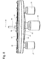
- FIGS. 6 to 8 an alternative embodiment of a drive 16 of an aircraft 10 according to the invention will now be described, the essential elements of the aircraft - similar, as in the illustration according to Fig. 4 - are omitted.
- Fig. 6 shows the drive 16 in a perspective view similar to the Fig. 4 , In Fig. 6 However, several design details are recognizable:
- the rotor drive shaft 29 is in the embodiment of FIGS. 6 to 8 formed by a spoked wheel 57, or includes such. This has, starting from a radial center a Variety of spokes 58 a, 58 b, which connect the center with an outer rim 62.
- an internal toothing 61 is arranged, which is formed completely circumferentially and having a plurality of teeth.
- Each electric motor 25, 26, 27 is associated with a pinion 30 a, 30 b, 30 c, which cooperates in a manner not shown with corresponding teeth of the internal teeth 61.
- the three pinions 30a, 30b, 30c are fixedly connected to one another with the aid of a triangular-shaped carrier element 60 or are firmly positioned relative to one another.
- the drive 16 is a stable construction with low weight.
- the rotor drive shaft 29 designed here as a spoke wheel 57 is provided with a flange connection 59, to which the connecting bolt 56, as in FIG Fig. 8 recognizable, attacks.
- the connecting bolt 56 is the - not shown - with the rotor drive shaft 59 rotationally connected rotor 12th
- the rotor axis 24 corresponds in the embodiment of Fig. 6 to 8 turn the axis of rotation 32 of the rotor drive shaft 29th
Landscapes
- Engineering & Computer Science (AREA)
- Aviation & Aerospace Engineering (AREA)
- Mechanical Engineering (AREA)
- Combustion & Propulsion (AREA)
- Chemical & Material Sciences (AREA)
- Remote Sensing (AREA)
- Computer Networks & Wireless Communication (AREA)
- General Engineering & Computer Science (AREA)
- Transportation (AREA)
- Manufacturing & Machinery (AREA)
- Power Engineering (AREA)
- Retarders (AREA)
- Connection Of Motors, Electrical Generators, Mechanical Devices, And The Like (AREA)
Applications Claiming Priority (1)
| Application Number | Priority Date | Filing Date | Title |
|---|---|---|---|
| DE102018107586.3A DE102018107586A1 (de) | 2018-03-29 | 2018-03-29 | Fluggerät |
Publications (1)
| Publication Number | Publication Date |
|---|---|
| EP3546352A1 true EP3546352A1 (fr) | 2019-10-02 |
Family
ID=65529514
Family Applications (1)
| Application Number | Title | Priority Date | Filing Date |
|---|---|---|---|
| EP19158797.1A Withdrawn EP3546352A1 (fr) | 2018-03-29 | 2019-02-22 | Aéronef |
Country Status (4)
| Country | Link |
|---|---|
| US (1) | US20190300193A1 (fr) |
| EP (1) | EP3546352A1 (fr) |
| CN (1) | CN110316366A (fr) |
| DE (1) | DE102018107586A1 (fr) |
Cited By (3)
| Publication number | Priority date | Publication date | Assignee | Title |
|---|---|---|---|---|
| WO2022101094A1 (fr) * | 2020-11-11 | 2022-05-19 | Zf Friedrichshafen Ag | Dispositif d'entraînement pour une hélice d'un multicoptère |
| US20220258873A1 (en) * | 2021-02-12 | 2022-08-18 | Bell Textron Inc. | Redundant Electric Propulsion System |
| US20240278923A1 (en) * | 2023-02-21 | 2024-08-22 | Honeywell International Inc. | Propulsor brake lock |
Families Citing this family (7)
| Publication number | Priority date | Publication date | Assignee | Title |
|---|---|---|---|---|
| JP7599679B2 (ja) * | 2020-07-13 | 2024-12-16 | eVTOL Japan株式会社 | 電動ヘリコプター |
| CN113022887B (zh) * | 2021-05-26 | 2021-08-10 | 中国空气动力研究与发展中心低速空气动力研究所 | 一种旋翼水洞试验装置 |
| FR3123325B1 (fr) * | 2021-05-28 | 2023-10-20 | Airbus Helicopters | Installation motrice de type modulaire pour un giravion et giravion associé |
| CN113883254B (zh) * | 2021-10-26 | 2023-06-23 | 南通睿动新能源科技有限公司 | 一种双电机纯电动减速箱防吸空系统 |
| US11691744B1 (en) | 2022-03-23 | 2023-07-04 | Beta Air, Llc | Dual-motor propulsion assembly |
| US12107459B2 (en) | 2022-03-25 | 2024-10-01 | Beta Air Llc | Rotor for an electric aircraft motor comprising a plurality of magnets |
| US11787550B1 (en) | 2022-05-04 | 2023-10-17 | Beta Air, Llc | Propulsor assembly powered by a dual motor system |
Citations (6)
| Publication number | Priority date | Publication date | Assignee | Title |
|---|---|---|---|---|
| WO2013162128A1 (fr) * | 2012-04-24 | 2013-10-31 | 유콘시스템 주식회사 | Système de véhicule aérien sans pilote pour raccordement de câbles |
| CN103826970A (zh) * | 2011-09-04 | 2014-05-28 | 埃里克·尚特里奥克斯 | 配备有自由轮的分布式电动装置的飞行器 |
| WO2016020915A1 (fr) * | 2014-08-04 | 2016-02-11 | Israel Aerospace Industries Ltd. | Ensemble système de propulsion |
| DE112015003310T5 (de) * | 2014-07-17 | 2017-03-30 | Japan Aerospace Exploration Agency | Motorisiertes Flugzeug und Verfahren zum Bestimmen der Leistung und Anzahl von Elektromotoren in dem motorisierten Flugzeug |
| WO2017114643A1 (fr) * | 2015-12-30 | 2017-07-06 | Siemens Aktiengesellschaft | Système d'entraînement électrique redondant pour l'entraînement d'un moyen de propulsion d'un aéronef et procédé d'entraînement du moyen de propulsion |
| DE102017105956A1 (de) | 2017-03-20 | 2018-09-20 | Riedel Communications International GmbH | Fluggerät, Funknetzwerk und Verfahren zur Übertragung von Informationen |
Family Cites Families (16)
| Publication number | Priority date | Publication date | Assignee | Title |
|---|---|---|---|---|
| GB1139941A (en) * | 1965-03-30 | 1969-01-15 | Rolls Royce | Engine drive |
| FR2568541B1 (fr) * | 1984-08-06 | 1987-03-20 | Aerospatiale | Boite de transmission principale pour helicoptere bimoteur |
| US4656890A (en) * | 1985-12-19 | 1987-04-14 | Dresser Industries, Inc. | Coupling for a planetary ring gear |
| US20020084120A1 (en) * | 2001-01-02 | 2002-07-04 | Beasley Leslie R. | Motor assembly with independent motor units |
| US8342440B2 (en) * | 2009-12-10 | 2013-01-01 | Regents Of The University Of Minnesota | Miniature robotic vehicle with ground and flight capability |
| FR2979614B1 (fr) * | 2011-09-04 | 2013-09-20 | Eric Chantriaux | Transmission electromagnetique de puissance pour aeronef a voilure tournante ou fixe. |
| US10144507B2 (en) * | 2014-08-28 | 2018-12-04 | Pascal Chretien | Electromagnetic distributed direct drive for aircraft |
| WO2016121072A1 (fr) * | 2015-01-29 | 2016-08-04 | 株式会社自律制御システム研究所 | Dispositif de robot volant |
| KR20170033625A (ko) * | 2015-09-17 | 2017-03-27 | 엘지전자 주식회사 | 드론 |
| WO2017117291A1 (fr) * | 2015-12-28 | 2017-07-06 | Dezso Molnar | Système d'aéronef sans pilote captif |
| JP2017182959A (ja) * | 2016-03-29 | 2017-10-05 | 日本電気株式会社 | 無人航空機、無人航空機制御システム、無人航空機制御方法 |
| CN206050087U (zh) * | 2016-09-19 | 2017-03-29 | 中电科芜湖钻石飞机设计研究院有限公司 | 混合动力飞机耦合系统 |
| CN106532828A (zh) * | 2016-11-28 | 2017-03-22 | 车以能 | 一种有源多旋翼无人机供电系统 |
| US11731772B2 (en) * | 2017-03-02 | 2023-08-22 | Textron Innovations Inc. | Hybrid propulsion drive train system for tiltrotor aircraft |
| CN107579433B (zh) * | 2017-09-05 | 2018-12-07 | 国网江苏省电力公司苏州供电公司 | 一种防雷方法和系统 |
| DE102018101556A1 (de) | 2017-11-28 | 2019-05-29 | Riedel Communications International GmbH | Fluggerät, Blitzschutzsystem und Verfahren zur Bereitstellung des Blitzschutzes |
-
2018
- 2018-03-29 DE DE102018107586.3A patent/DE102018107586A1/de not_active Ceased
-
2019
- 2019-02-22 US US16/282,359 patent/US20190300193A1/en not_active Abandoned
- 2019-02-22 EP EP19158797.1A patent/EP3546352A1/fr not_active Withdrawn
- 2019-03-28 CN CN201910240171.4A patent/CN110316366A/zh active Pending
Patent Citations (6)
| Publication number | Priority date | Publication date | Assignee | Title |
|---|---|---|---|---|
| CN103826970A (zh) * | 2011-09-04 | 2014-05-28 | 埃里克·尚特里奥克斯 | 配备有自由轮的分布式电动装置的飞行器 |
| WO2013162128A1 (fr) * | 2012-04-24 | 2013-10-31 | 유콘시스템 주식회사 | Système de véhicule aérien sans pilote pour raccordement de câbles |
| DE112015003310T5 (de) * | 2014-07-17 | 2017-03-30 | Japan Aerospace Exploration Agency | Motorisiertes Flugzeug und Verfahren zum Bestimmen der Leistung und Anzahl von Elektromotoren in dem motorisierten Flugzeug |
| WO2016020915A1 (fr) * | 2014-08-04 | 2016-02-11 | Israel Aerospace Industries Ltd. | Ensemble système de propulsion |
| WO2017114643A1 (fr) * | 2015-12-30 | 2017-07-06 | Siemens Aktiengesellschaft | Système d'entraînement électrique redondant pour l'entraînement d'un moyen de propulsion d'un aéronef et procédé d'entraînement du moyen de propulsion |
| DE102017105956A1 (de) | 2017-03-20 | 2018-09-20 | Riedel Communications International GmbH | Fluggerät, Funknetzwerk und Verfahren zur Übertragung von Informationen |
Cited By (4)
| Publication number | Priority date | Publication date | Assignee | Title |
|---|---|---|---|---|
| WO2022101094A1 (fr) * | 2020-11-11 | 2022-05-19 | Zf Friedrichshafen Ag | Dispositif d'entraînement pour une hélice d'un multicoptère |
| US20220258873A1 (en) * | 2021-02-12 | 2022-08-18 | Bell Textron Inc. | Redundant Electric Propulsion System |
| US11661185B2 (en) * | 2021-02-12 | 2023-05-30 | Textron Innovations Inc. | Redundant electric propulsion system |
| US20240278923A1 (en) * | 2023-02-21 | 2024-08-22 | Honeywell International Inc. | Propulsor brake lock |
Also Published As
| Publication number | Publication date |
|---|---|
| US20190300193A1 (en) | 2019-10-03 |
| DE102018107586A1 (de) | 2019-10-02 |
| CN110316366A (zh) | 2019-10-11 |
Similar Documents
| Publication | Publication Date | Title |
|---|---|---|
| EP3546352A1 (fr) | Aéronef | |
| DE69727065T2 (de) | Konzentrisches kronradgetriebe | |
| EP3027455B1 (fr) | Chaîne cinématique d'un véhicule automobile | |
| EP3323717B1 (fr) | Mât rotor | |
| EP3581830A1 (fr) | Système d'engrenage | |
| EP4136023B1 (fr) | Actionneur pour applications aéronautiques | |
| EP3810505B1 (fr) | Giravion équipé d'un entraînement électrique pour entraîner un rotor principal et/ou un rotor anticouple du giravion | |
| EP1167822B1 (fr) | Dispositif pour la production d'un mouvement rotatif ou linéaire | |
| EP2657059B1 (fr) | Dispositif d'entraînement pour essieu tandem | |
| EP3491238B1 (fr) | Bâti machine et rotor pour éolienne et procédé correspondant | |
| DE102008035091A1 (de) | Antriebsvorrichtung zum unabhängigen Antreiben von mindestens zwei koaxial zueinander angeordneten Körpern | |
| DE2119974C2 (de) | Richtungssteuervorrichtung für ein Luftfahrzeug | |
| DE672606C (de) | Windkraftmaschine mit Schwenkwerk | |
| EP2951431B1 (fr) | Dispositif de commande pour un système de lacet d'éolienne | |
| DE102015004525B4 (de) | Lenkbares Flugzeugfahrwerk | |
| EP3334638B1 (fr) | Ensemble de direction assistée à superposition de couple de braquage | |
| DE102008015400B4 (de) | Differentialanordnung zur gesteuerten Verteilung eines Antriebsmomentes | |
| EP3104503B1 (fr) | Entrainement rotatif sans jeu | |
| DE102021113127A1 (de) | Antriebs- und/oder Verstellvorrichtung mit Überlastschutz | |
| DE102020106334A1 (de) | Verzweigungsgetriebe mit Momentenausgleich | |
| DE102014100718A1 (de) | Hinterachslenkung für Kraftfahrzeuge und Verfahren zu deren Betrieb | |
| WO2024115085A1 (fr) | Chaîne cinématique pour aéronef flottant | |
| DE102019125156A1 (de) | Achsantrieb | |
| DE102020120683A1 (de) | Rotorwellenanordnung | |
| DE102015113156B4 (de) | Aktiver Radträger für ein Fahrzeug und Fahrwerk für ein Kraftfahrzeug sowie Fahrzeug |
Legal Events
| Date | Code | Title | Description |
|---|---|---|---|
| PUAI | Public reference made under article 153(3) epc to a published international application that has entered the european phase |
Free format text: ORIGINAL CODE: 0009012 |
|
| STAA | Information on the status of an ep patent application or granted ep patent |
Free format text: STATUS: THE APPLICATION HAS BEEN PUBLISHED |
|
| AK | Designated contracting states |
Kind code of ref document: A1 Designated state(s): AL AT BE BG CH CY CZ DE DK EE ES FI FR GB GR HR HU IE IS IT LI LT LU LV MC MK MT NL NO PL PT RO RS SE SI SK SM TR |
|
| AX | Request for extension of the european patent |
Extension state: BA ME |
|
| STAA | Information on the status of an ep patent application or granted ep patent |
Free format text: STATUS: REQUEST FOR EXAMINATION WAS MADE |
|
| 17P | Request for examination filed |
Effective date: 20200327 |
|
| RBV | Designated contracting states (corrected) |
Designated state(s): AL AT BE BG CH CY CZ DE DK EE ES FI FR GB GR HR HU IE IS IT LI LT LU LV MC MK MT NL NO PL PT RO RS SE SI SK SM TR |
|
| STAA | Information on the status of an ep patent application or granted ep patent |
Free format text: STATUS: THE APPLICATION IS DEEMED TO BE WITHDRAWN |
|
| 18D | Application deemed to be withdrawn |
Effective date: 20210901 |