EP3546242B1 - Resonator wheel - Google Patents
Resonator wheel Download PDFInfo
- Publication number
- EP3546242B1 EP3546242B1 EP18877311.3A EP18877311A EP3546242B1 EP 3546242 B1 EP3546242 B1 EP 3546242B1 EP 18877311 A EP18877311 A EP 18877311A EP 3546242 B1 EP3546242 B1 EP 3546242B1
- Authority
- EP
- European Patent Office
- Prior art keywords
- flange
- wheel rim
- annular wall
- resonance
- tube
- Prior art date
- Legal status (The legal status is an assumption and is not a legal conclusion. Google has not performed a legal analysis and makes no representation as to the accuracy of the status listed.)
- Active
Links
Images



Classifications
-
- B—PERFORMING OPERATIONS; TRANSPORTING
- B60—VEHICLES IN GENERAL
- B60B—VEHICLE WHEELS; CASTORS; AXLES FOR WHEELS OR CASTORS; INCREASING WHEEL ADHESION
- B60B21/00—Rims
- B60B21/12—Appurtenances, e.g. lining bands
-
- B—PERFORMING OPERATIONS; TRANSPORTING
- B60—VEHICLES IN GENERAL
- B60C—VEHICLE TYRES; TYRE INFLATION; TYRE CHANGING; CONNECTING VALVES TO INFLATABLE ELASTIC BODIES IN GENERAL; DEVICES OR ARRANGEMENTS RELATED TO TYRES
- B60C19/00—Tyre parts or constructions not otherwise provided for
- B60C19/002—Noise damping elements provided in the tyre structure or attached thereto, e.g. in the tyre interior
-
- B—PERFORMING OPERATIONS; TRANSPORTING
- B60—VEHICLES IN GENERAL
- B60B—VEHICLE WHEELS; CASTORS; AXLES FOR WHEELS OR CASTORS; INCREASING WHEEL ADHESION
- B60B21/00—Rims
- B60B21/02—Rims characterised by transverse section
- B60B21/026—Rims characterised by transverse section the shape of rim well
-
- B—PERFORMING OPERATIONS; TRANSPORTING
- B60—VEHICLES IN GENERAL
- B60B—VEHICLE WHEELS; CASTORS; AXLES FOR WHEELS OR CASTORS; INCREASING WHEEL ADHESION
- B60B25/00—Rims built-up of several main parts ; Locking means for the rim parts
- B60B25/22—Other apurtenances, e.g. for sealing the component parts enabling the use of tubeless tyres
-
- B—PERFORMING OPERATIONS; TRANSPORTING
- B60—VEHICLES IN GENERAL
- B60B—VEHICLE WHEELS; CASTORS; AXLES FOR WHEELS OR CASTORS; INCREASING WHEEL ADHESION
- B60B2900/00—Purpose of invention
- B60B2900/10—Reduction of
- B60B2900/131—Vibrations
-
- B—PERFORMING OPERATIONS; TRANSPORTING
- B60—VEHICLES IN GENERAL
- B60B—VEHICLE WHEELS; CASTORS; AXLES FOR WHEELS OR CASTORS; INCREASING WHEEL ADHESION
- B60B2900/00—Purpose of invention
- B60B2900/10—Reduction of
- B60B2900/133—Noise
Definitions
- the present disclosure relates to a resonator wheel.
- an automobile tire is filled with air while being coupled to a wheel rim, and serves to elastically support a vehicle body through shock absorbing action of air inside the tire.
- Resonance in the internal space of the tire generates resonance sound having a sharp peak in a frequency band of 200 Hz to 300 Hz.
- the resonance sound is transmitted to the interior of the vehicle, causing noise that causes driver discomfort. Further, continuous noise deteriorates ride comfort.
- a resonance tube based on a Helmholtz resonator principle is mounted on a wheel rim to attenuate resonance sound generated in the internal space of the tire.
- the conventional resonance tube is mounted on the wheel rim by inserting the flanges of the resonance tube into insertion grooves formed at both axial ends of the wheel rim.
- the conventional resonance tube is mounted on the wheel rim by sequentially inserting a flange formed on one side of the resonance tube into an insertion groove formed on one side of the wheel rim and then inserting a flange formed on the other side of the resonance tube into an insertion groove formed on the other side of the wheel rim.
- the conventional resonance tube is generally made of a plastic material capable of elastic deformation.
- the resonance tubes when plural resonance tubes are to be mounted on the wheel rim, the resonance tubes should be mounted one by one by inserting the flanges of each of the resonance tubes into both insertion grooves, which is cumbersome.
- EP2962866A1 describes in its abstract a vehicle wheel including a sub air chamber member which serves as a Helmholtz resonator and is fixed to an outer circumferential surface of a well portion in a tire air chamber; a first standing wall surface formed such as to stand from the outer circumferential surface of the well portion outward in radial direction and extend in circumferential direction of the outer circumferential surface; and a second standing wall surface formed on the well portion such as to face the first standing wall surface in width direction of the outer circumferential surface.
- a resonator wheel including a wheel rim; a first annular wall protruding from an outer circumferential surface of the wheel rim along a circumference of the wheel rim, the first annular wall including a tube mounting groove formed on one side surface of the first annular wall; a second annular wall protruding from the outer circumferential surface of the wheel rim along the circumference of the wheel rim and spaced apart from the first annular wall; a plurality of resonance tubes disposed on the outer circumferential surface of the wheel rim between the first annular wall and the second annular wall, each of the resonance tubes including: a tube body including a resonance chamber and a communication hole extending from the resonance chamber; a first flange protruding from one side of the tube body and having one end inserted into the tube mounting groove; and a second flange protruding from an opposite side of the tube body and having one end disposed adjacent to the second annular wall; and a fastening
- a resonance tube may be pressed radially inward on a wheel rim using a fastening member. Thereby, the resonance tube may be prevented from being separated from the wheel rim. As a result, the resonance tube may be more securely mounted on the wheel rim.
- mounting a plurality of resonance tubes on the wheel rim may be completed at one time using a fastening member after the resonance tubes are provisionally mounted. Accordingly, the plurality of resonance tubes may be easily mounted.
- FIG. 1 is a perspective view of a resonator wheel 10 according to one embodiment of the present disclosure.
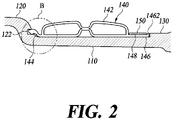
- FIG. 2 is a cross-sectional view of the resonator wheel 10 according to one embodiment of the present disclosure.
- the resonator wheel includes a wheel rim 110, a first annular wall 120, a second annular wall 130, a resonance tube 140, and a fastening member 150.
- the wheel rim 110 refers to an annular portion formed on the radially outer side of a vehicle wheel.
- a vehicle tire, the resonance tube 140, and the like may be mounted on the wheel rim 110.
- the terms “radial,” “circumferential,” and “axial” directions refer to the radial direction of the wheel rim 110, the circumferential direction of the wheel rim 110 and the axial direction of the wheel rim 110, respectively.
- the first annular wall 120 protrudes from the outer circumferential surface of the wheel rim 110 along the circumference of the wheel rim 110.
- the first annular wall 120 includes a tube mounting groove 122 formed on one side surface of the first annular wall 120.
- the second annular wall 130 protrudes from the outer circumferential surface of the wheel rim 110 along the circumference of the wheel rim 110 and is disposed spaced apart from the first annular wall 120.
- a plurality of resonance tubes 140 is disposed on the outer circumferential surface of the wheel rim 110 between the first annular wall 120 and the second annular wall 130.
- Each resonance tube 140 includes a tube body 142, a first flange 144, and a second flange 146.
- the tube body 142 includes a resonance chamber 1422 and a communication hole 1424 extending from the resonance chamber 1422.
- the communication hole 1424 may be a hole through which the resonance chamber 1422 communicates with the space outside the resonance chamber 1422.
- the resonance tube 140 employs the principle of Helmholtz resonance to attenuate noise generated in the wheel.
- a Helmholtz resonator consists of an internal space and a neck portion through which the internal space communicates with a region outside the internal space.
- the Helmholtz resonator forms a vibration system as the air in the neck portion acts as a mass and the air in the internal space acts as a spring.
- resonance occurs at a specific frequency, a so-called resonance frequency.
- the air around the neck portion repeatedly vigorously exits and enters the neck portion, causing continuous friction between the tube wall of the neck portion and the air in the neck portion.
- the vibration energy is converted into thermal energy by friction, and thus sound absorption is carried out.
- the resonance chamber 1422 and the communication hole 1424 of the tube body 142 are components corresponding to the internal space and the neck portion of the Helmholtz resonator described above, respectively. Accordingly, the resonance tube 140 attenuates noise generated in the wheel based on the Helmholtz resonator principle described above.
- the plurality of resonance tubes 140 may have different resonance frequencies.
- the resonant frequency of the Helmholtz resonator is determined by factors such as the effective diameter of the neck portion, the length of the neck portion, the cross-sectional area of the neck portion, and the volume of the internal space.
- the resonance tubes 140 may be designed to have a specific resonance frequency that may attenuate noise generated in the wheel, by adjusting the values of the above-described factors. However, each resonance tube 140 has only one resonance frequency. Accordingly, when a plurality of resonance tubes 140 has the same resonance frequency, the frequency range in which sound absorption occurs may be limited to a narrow range around the resonance frequency.
- the resonator wheel 10 intentionally allows the plurality of resonance tubes 140 to have different resonance frequencies, thereby achieving noise attenuation in a wider frequency range.
- the first flange 144 protrudes from one side of the tube body 142 and thus one end of the first flange 144 is inserted into the tube mounting groove 122.
- the resonance tube 140 can be provisionally mounted on the outer circumferential surface of the wheel rim 110 before the resonance tube 140 is fastened by the fastening member 150. Details regarding the provisional mounting of the resonance tube 140 will be described with reference to FIG. 3 .
- the first flange 144 may include an elastic region 1442 and an insertion region 1444.
- the insertion region 1444 may include a downward slope and an elastic fitting projection 510.
- the elastic region 1442 and the insertion region 1444 will be described in detail with reference to FIG. 5 .
- the second flange 146 protrudes from the other side of the tube body 142 such that one end of the second flange 146 is disposed adjacent to the second annular wall 130.
- one end of the second flange 146 may be in contact with the second annular wall 130 with the resonance tube 140 mounted on the outer circumferential surface of the wheel rim 110.
- a rotation preventing projection 1464 may be formed at one end of the second flange 146 to prevent circumferential rotation of the resonance tube 140 on the outer circumferential surface of the wheel rim 110. A detailed description of the rotation preventing projection 1464 will be given with reference to FIG. 4 .
- the fastening member 150 is disposed between the tube body 142 and the second annular wall 130 to surround one radially outer surface of the second flange 146 along the circumference of the wheel rim 110.
- the fastening member 150 surrounds one surface of the second flange 146, the fastening member presses the second flange 146 in the radially inward direction of the wheel rim 110.
- the resonance tube 140 may be prevented from being separated from the outer circumferential surface of the wheel rim 110.
- the second flange 146 may include a fastening member seating step 1462 protruding from one surface of the second flange 146.
- the fastening member seating step 1462 may define a fastening groove 148 between the tube body 142 and the fastening member seating step 1462, and the fastening member 150 may be mounted in the fastening groove 148.
- the resonator wheel 10 may prevent the axial movement of the fastening member 150 on one surface of the second flange 146 by mounting the fastening member 150 in the fastening groove 148. Further, the mounting position of the fastening member 150 may be marked such that the fastening member 150 can be conveniently mounted on one surface of the second flange 146.
- the fastening groove 148 may have a greater axial width, thereby allowing the fastening member 150 having a greater axial width to be mounted in the fastening groove 148. Since the fastening member 150 having a greater axial width has higher durability and rigidity, it may press the resonance member 140 more strongly.
- the fastening groove 148 is formed by utilizing one side surface of the tube body 142 facing the second annular wall 130, the fastening groove 148 may be formed by one fastening member seating step 1462 alone, and thus the axial width of the fastening groove 148 may be increased compared to a case where two seating steps are utilized.
- the fastening member seating step 1462 may protrude from one end of the second flange 146. Thus, the fastening member seating step 1462 may adjoin or contact the second annular wall 130 with the resonance tube 140 mounted on the outer circumferential surface of the wheel rim 110.
- the second flange 146 and the second annular wall 130 face each other over a wider area. Accordingly, when the second flange 146 presses the second annular wall 130, the reaction force of the second annular wall 130 is applied to the first annular wall 146 over a wider area. In this case, the axial movement of the resonance tube 140 may be more securely prevented.
- the fastening member 150 presses the second flange 146 in the radially inward direction, tensile stress is generated in the fastening member 150. To apply more force in the radially inward direction, the fastening member 150 may be more strongly tightened. Then, larger tensile stress is generated in the fastening member 150.
- the fastening member 150 is required to withstand high tensile stress. Accordingly, the fastening member 150 may be formed of a metal material having sufficient stiffness, such as stainless steel.
- FIG. 3 illustrates a process of mounting the resonance tube 140 on a wheel rim 110 according to one embodiment of the present disclosure.
- a plurality of resonance tubes 140 may be mounted on the outer circumferential surface of the wheel rim 110, following sequential operations shown in FIGS. 3(a), 3(b) and 3(c) .
- the resonance tubes 140 of the plurality of resonance tubes 140 may be spaced apart from each other.
- the plurality of resonance tubes 140 may be provisionally mounted on the wheel rim 110.
- the resonance tubes 140 are pressed in the radially inward direction using the fastening member 150 to mount the resonance tubes 140 on the outer circumferential surface of the wheel rim 110. Because of this mounting method of the resonance tubes 140, the resonator wheel 10 according to the present disclosure requires a provisional mounting process of temporarily mounting the resonance tubes 140 on the outer circumferential surface of the wheel rim 110 before the resonance tubes 140 are mounted by arranging the fastening member 150.
- the most commonly conceivable method for provisional mounting is to annularly arrange a plurality of resonance tubes connected to each other on the outer circumferential surface of the wheel rim.
- this provisional mounting method is disadvantageous in that an additional process of connecting the plurality of resonance tubes is required.
- this mounting method is disadvantageous in that the resonance tubes are vulnerable to axial movement even after the fastening member is mounted.
- the resonator wheel 10 adopts the provisional mounting method of inserting the first flange 144 of the resonance tube 140 into the tube mounting groove 122 of the first annular wall 120, the plurality of resonance tubes 140 may be provisionally mounted on the wheel rim 110 while being spaced apart from each other.
- axial movement of the resonance tubes 140 may be prevented.
- the fastening member 150 is mounted so as to surround one surface of the second flange 146 with the plurality of resonance tubes 140 provisionally mounted on the wheel rim 110. Then, the fastening member 150 may press the resonance tubes 140 radially inward.
- the resonator wheel 10 may complete the mounting of the resonance tubes 140 on the wheel rim 110.
- FIG. 4 is an enlarged perspective view of area A of FIG. 1 in the resonator wheel 10 according to one embodiment of the present disclosure.
- the second flange 146 may include a rotation preventing projection 1464 protruding from one end of the second flange 146, and the second annular wall 130 may include a projection mounting groove 132 formed on one side surface of the second annular wall 130.
- the rotation preventing projection 1464 may be inserted into the projection mounting groove 132. Thereby, the resonance tube 140 may be prevented from moving in the circumferential direction on the outer circumferential surface of the wheel rim 110.
- the projection mounting groove 132 indicates positions where the plurality of resonance tubes 140 is to be disposed on the outer circumferential surface of the wheel rim 110, thereby guiding the plurality of resonance tubes 140 so as to be aligned on the outer circumferential surface of the wheel rim 110.
- a plurality of rotation preventing projections 1464 may be formed at one end of the second flange 146. Specifically, a pair of rotation preventing projections 1464 may be formed at both circumferential ends of the second flange 146, respectively.
- the rotation preventing projection 1464 may be shaped such that the circumferential width of the rotation preventing projection 1464 decreases as the rotation preventing projection 1464 extends from the second flange 146.
- the projection mounting groove 132 may be shaped such that the circumferential width of the second annular wall 130 decreases as it extends axially inward.
- the resonance tube 140 according to the present disclosure is mounted on the outer circumferential surface of the wheel rim 110 with one end of the first flange 144 inserted into the tube mounting groove 122. Once mounted, the resonance tube 140 cannot be separated radially outwardly. In order to separate the resonance tube 140, the resonance tube 140 needs to be pushed toward the second annular wall 130 to separate the first flange 144 from the tube mounting groove 122.
- the rotation preventing projection 1464 needs to be separated from the projection mounting groove 132 by pushing the resonance tube 140 toward the first annular wall 120 before the first flange 144 is separated from the tube mounting groove 122.
- the rotation preventing projection 1464 and the projection mounting groove 132 are shaped to have a gradually decreasing circumferential width. Accordingly, when the rotation preventing projection 1464 is separated from the projection mounting groove 132 by pushing the resonance tube 140 toward the first annular wall 120, the resonance tube 140 may be allowed to move in the circumferential direction within a certain range with the rotation preventing projection 1464 slightly separated from the projection mounting groove 132. Then, the resonance tube 140 may be more easily separated from the outer circumferential surface of the wheel rim 110.
- FIG. 5 is an enlarged cross-sectional view of area B of FIG. 2 in the resonator wheel 10 according to one embodiment of the present disclosure.
- the first flange 144 may include an elastic region 1442 formed between one end of the first flange 144 and the tube body 142.
- the elastic region 1442 refers to an area of the first flange 144 having an elastic material.
- the elastic region 1442 may be elastically deformed to urge the tube body 142 toward the second annular wall 130 when the resonance tube 140 is mounted on the outer circumferential surface of the wheel rim 110.
- the resonance tube 140 may be axially securely mounted on the outer circumferential surface of the wheel rim 110.
- the elastic region 1442 may include an elastic fold.
- the elastic fold may include at least one fold structure in the elastic region 1442.
- the elastic fold may cause a larger elastic deformation to occur within a confined space between one end of the first flange 144 and the tube body 142 through the fold structure formed of an elastic material.
- the resonance tube 140 is more axially securely mounted on the outer circumferential surface of the wheel rim 110.
- the first flange 144 may include an insertion region 1444, which is formed at one end of the first flange 144.
- the insertion region 1444 refers to an area of the first flange 144 that is inserted into the tube mounting groove 122 of the first annular wall 120.
- One radially outer surface of the insertion region 1444 may have a downward slope inclined toward the tube mounting groove 122.
- the downward slope formed on one surface of the insertion region 1444 allows one end of the first flange 144 to be readily inserted into the tube mounting groove 122 even when there is a tolerance in the radial width of the tube mounting groove 122 or the radial thickness of one end of the first flange 144.
- An elastic fitting projection 510 may be formed on the opposite surface of the insertion region 1444. When the insertion region 1444 is mounted in the tube mounting groove 122, the elastic fitting projection 510 may be elastically deformed to press the insertion region 1444 radially outward.
- one end of the first flange 144 inserted into the tube mounting groove 122 through the downward slope of the insertion region 1444 may be securely fixed to the tube mounting groove 122 by the elastic deformation of the elastic fitting projection 510, irrespective of the degree of tolerance in the radial width of the tube mounting groove 122 or the radial thickness of one end of the first flange 144.
- Resonator wheel 110 Wheel rim
- First annular wall 122 Tube mounting groove 130: Second annular wall 132: Protrusion mounting groove
- Resonance tube 142 Tube body 144: First flange 146: Second flange 148: Fastening groove 150: Fastening member 510: Elastic fitting projection 1422: Resonance chamber 1424: Communication hole 1442: Elastic region 1444: Insertion region 1464: Rotation preventing projection
Landscapes
- Engineering & Computer Science (AREA)
- Mechanical Engineering (AREA)
- Tires In General (AREA)
- Measuring Fluid Pressure (AREA)
Description
- The present disclosure relates to a resonator wheel.
- The statements in this section merely provide background information related to the present disclosure and may not constitute prior art.
- Generally, an automobile tire is filled with air while being coupled to a wheel rim, and serves to elastically support a vehicle body through shock absorbing action of air inside the tire.
- During travel of the vehicle, friction continuously occurs between the tire and the road surface. Then, the side wall of the tire vibrates due to the vibration action of the tire on the road surface, and resonance occurs in the internal space of the tire due to vibration of the side wall.
- Resonance in the internal space of the tire generates resonance sound having a sharp peak in a frequency band of 200 Hz to 300 Hz. The resonance sound is transmitted to the interior of the vehicle, causing noise that causes driver discomfort. Further, continuous noise deteriorates ride comfort.
- Conventionally, in order to address the above-mentioned issue, a resonance tube based on a Helmholtz resonator principle is mounted on a wheel rim to attenuate resonance sound generated in the internal space of the tire. Specifically, the conventional resonance tube is mounted on the wheel rim by inserting the flanges of the resonance tube into insertion grooves formed at both axial ends of the wheel rim.
- The conventional resonance tube is mounted on the wheel rim by sequentially inserting a flange formed on one side of the resonance tube into an insertion groove formed on one side of the wheel rim and then inserting a flange formed on the other side of the resonance tube into an insertion groove formed on the other side of the wheel rim. Accordingly, the conventional resonance tube is generally made of a plastic material capable of elastic deformation.
- However, in the case of such conventional sequential mounting method of the resonance tube, at least one of the flanges of the resonance tube inserted into the two insertion grooves is insufficiently inserted. Accordingly, the conventional resonance tube is often detached from the wheel rim.
- In the conventional sequential mounting method of the resonance tube, when plural resonance tubes are to be mounted on the wheel rim, the resonance tubes should be mounted one by one by inserting the flanges of each of the resonance tubes into both insertion grooves, which is cumbersome.
-
EP2962866A1 describes in its abstract a vehicle wheel including a sub air chamber member which serves as a Helmholtz resonator and is fixed to an outer circumferential surface of a well portion in a tire air chamber; a first standing wall surface formed such as to stand from the outer circumferential surface of the well portion outward in radial direction and extend in circumferential direction of the outer circumferential surface; and a second standing wall surface formed on the well portion such as to face the first standing wall surface in width direction of the outer circumferential surface. - Accordingly, it is one object of the present invention to provide a resonance
tube mounting method capable of preventing a resonance tube from being separated from a wheel rim such that the resonance tube is more securely mounted on the wheel rim. - It is another object of the present invention to provide a resonance tube mounting method that may facilitate mounting of a plurality of resonance tubes on the wheel rim.
- In accordance with one aspect of the present invention, provided is a resonator wheel including a wheel rim; a first annular wall protruding from an outer circumferential surface of the wheel rim along a circumference of the wheel rim, the first annular wall including a tube mounting groove formed on one side surface of the first annular wall; a second annular wall protruding from the outer circumferential surface of the wheel rim along the circumference of the wheel rim and spaced apart from the first annular wall; a plurality of resonance tubes disposed on the outer circumferential surface of the wheel rim between the first annular wall and the second annular wall, each of the resonance tubes including: a tube body including a resonance chamber and a communication hole extending from the resonance chamber; a first flange protruding from one side of the tube body and having one end inserted into the tube mounting groove; and a second flange protruding from an opposite side of the tube body and having one end disposed adjacent to the second annular wall; and a fastening member surrounding one radially outer surface of the second flange between the tube body and the second annular wall along the circumference of the wheel rim, the fastening member pressing the second flange in a radially inward direction of the wheel rim.
- As described above, according to the present disclosure, a resonance tube may be pressed radially inward on a wheel rim using a fastening member. Thereby, the resonance tube may be prevented from being separated from the wheel rim. As a result, the resonance tube may be more securely mounted on the wheel rim.
- In addition, mounting a plurality of resonance tubes on the wheel rim may be completed at one time using a fastening member after the resonance tubes are provisionally mounted. Accordingly, the plurality of resonance tubes may be easily mounted.
-
-
FIG. 1 is a perspective view of a resonator wheel according to one embodiment of the present disclosure. -
FIG. 2 is a cross-sectional view of the resonator wheel according to one embodiment of the present disclosure. -
FIG. 3 illustrates a process of mounting the resonance tube on a wheel rim according to one embodiment of the present disclosure. -
FIG. 4 is an enlarged perspective view of area A ofFIG. 1 in the resonator wheel according to one embodiment of the present disclosure. -
FIG. 5 is an enlarged cross-sectional view of area B ofFIG. 2 in the resonator wheel according to one embodiment of the present disclosure. - Hereinafter, some embodiments of the present invention will be described in detail with reference to the accompanying drawings. It should be noted that, in adding reference numerals to the constituent elements in the respective drawings, like reference numerals designate like elements, although the elements are shown in different drawings. Further, in the following description of the present invention, a detailed description of known functions and configurations incorporated herein will be omitted when it may make the subject matter of the present invention rather unclear.
- In describing the components of the embodiment according to the present invention, various terms such as first, second, i), ii), a), b) and the like may be used. These terms are used solely for the purpose of distinguishing one component from another, but neither implies nor suggests the substances, the order or sequence of the components. Throughout this specification, when a part "includes" or "comprises" a component, the part may further include other components, and such other components are not excluded unless there is a particular description contrary thereto.
-
FIG. 1 is a perspective view of aresonator wheel 10 according to one embodiment of the present disclosure. -
FIG. 2 is a cross-sectional view of theresonator wheel 10 according to one embodiment of the present disclosure. - Referring to
FIGS. 1 and2 , the resonator wheel includes awheel rim 110, a firstannular wall 120, a secondannular wall 130, aresonance tube 140, and afastening member 150. - The
wheel rim 110 refers to an annular portion formed on the radially outer side of a vehicle wheel. A vehicle tire, theresonance tube 140, and the like may be mounted on thewheel rim 110. - In the description of the
resonator wheel 10 according to the present disclosure, which will be described below, the terms "radial," "circumferential," and "axial" directions refer to the radial direction of thewheel rim 110, the circumferential direction of thewheel rim 110 and the axial direction of thewheel rim 110, respectively. - The first
annular wall 120 protrudes from the outer circumferential surface of thewheel rim 110 along the circumference of thewheel rim 110. In addition, the firstannular wall 120 includes atube mounting groove 122 formed on one side surface of the firstannular wall 120. - The second
annular wall 130 protrudes from the outer circumferential surface of thewheel rim 110 along the circumference of thewheel rim 110 and is disposed spaced apart from the firstannular wall 120. - A plurality of
resonance tubes 140 is disposed on the outer circumferential surface of thewheel rim 110 between the firstannular wall 120 and the secondannular wall 130. - Each
resonance tube 140 includes atube body 142, afirst flange 144, and asecond flange 146. - The
tube body 142 includes aresonance chamber 1422 and acommunication hole 1424 extending from theresonance chamber 1422. Thecommunication hole 1424 may be a hole through which theresonance chamber 1422 communicates with the space outside theresonance chamber 1422. - The
resonance tube 140 according to the present disclosure employs the principle of Helmholtz resonance to attenuate noise generated in the wheel. - A Helmholtz resonator consists of an internal space and a neck portion through which the internal space communicates with a region outside the internal space. The Helmholtz resonator forms a vibration system as the air in the neck portion acts as a mass and the air in the internal space acts as a spring.
- In such a vibration system, resonance occurs at a specific frequency, a so-called resonance frequency. When resonance occurs in the Helmholtz resonator, the air around the neck portion repeatedly vigorously exits and enters the neck portion, causing continuous friction between the tube wall of the neck portion and the air in the neck portion. As a result, the vibration energy is converted into thermal energy by friction, and thus sound absorption is carried out.
- In the
resonance tube 140 according to the present disclosure, theresonance chamber 1422 and thecommunication hole 1424 of thetube body 142 are components corresponding to the internal space and the neck portion of the Helmholtz resonator described above, respectively. Accordingly, theresonance tube 140 attenuates noise generated in the wheel based on the Helmholtz resonator principle described above. - The plurality of
resonance tubes 140 may have different resonance frequencies. The resonant frequency of the Helmholtz resonator is determined by factors such as the effective diameter of the neck portion, the length of the neck portion, the cross-sectional area of the neck portion, and the volume of the internal space. - That is, the
resonance tubes 140 may be designed to have a specific resonance frequency that may attenuate noise generated in the wheel, by adjusting the values of the above-described factors. However, eachresonance tube 140 has only one resonance frequency. Accordingly, when a plurality ofresonance tubes 140 has the same resonance frequency, the frequency range in which sound absorption occurs may be limited to a narrow range around the resonance frequency. - Accordingly, the
resonator wheel 10 according to one embodiment of the present disclosure intentionally allows the plurality ofresonance tubes 140 to have different resonance frequencies, thereby achieving noise attenuation in a wider frequency range. - The
first flange 144 protrudes from one side of thetube body 142 and thus one end of thefirst flange 144 is inserted into thetube mounting groove 122. - For the
resonator wheel 10 according to the present disclosure, as one end of thefirst flange 144 is inserted into thetube mounting groove 122, theresonance tube 140 can be provisionally mounted on the outer circumferential surface of thewheel rim 110 before theresonance tube 140 is fastened by thefastening member 150. Details regarding the provisional mounting of theresonance tube 140 will be described with reference toFIG. 3 . - The
first flange 144 may include anelastic region 1442 and aninsertion region 1444. Theinsertion region 1444 may include a downward slope and an elasticfitting projection 510. Theelastic region 1442 and theinsertion region 1444 will be described in detail with reference toFIG. 5 . - Referring again to
FIGS. 1 and2 , thesecond flange 146 protrudes from the other side of thetube body 142 such that one end of thesecond flange 146 is disposed adjacent to the secondannular wall 130. - In order to prevent the axial movement of the
resonance tube 140, one end of thesecond flange 146 may be in contact with the secondannular wall 130 with theresonance tube 140 mounted on the outer circumferential surface of thewheel rim 110. - In addition, a
rotation preventing projection 1464 may be formed at one end of thesecond flange 146 to prevent circumferential rotation of theresonance tube 140 on the outer circumferential surface of thewheel rim 110. A detailed description of therotation preventing projection 1464 will be given with reference toFIG. 4 . - Referring again to
FIGS. 1 and2 , thefastening member 150 is disposed between thetube body 142 and the secondannular wall 130 to surround one radially outer surface of thesecond flange 146 along the circumference of thewheel rim 110. - As the
fastening member 150 surrounds one surface of thesecond flange 146, the fastening member presses thesecond flange 146 in the radially inward direction of thewheel rim 110. Thus, theresonance tube 140 may be prevented from being separated from the outer circumferential surface of thewheel rim 110. - In addition, since the
resonance tube 140 is pressed by thefastening member 150 in the radially inward direction, normal force applied to theresonance tube 140 by the outer circumferential surface of thewheel rim 110 also becomes strong. As a result, stronger frictional force may be generated between theresonance tube 140 and thewheel rim 110, thereby preventing the circumferential or axial movement of theresonance tube 140 on the outer circumferential surface of thewheel rim 110. - Referring to
FIG. 2 , thesecond flange 146 may include a fasteningmember seating step 1462 protruding from one surface of thesecond flange 146. The fasteningmember seating step 1462 may define afastening groove 148 between thetube body 142 and the fasteningmember seating step 1462, and thefastening member 150 may be mounted in thefastening groove 148. - The
resonator wheel 10 according to one embodiment of the present disclosure may prevent the axial movement of thefastening member 150 on one surface of thesecond flange 146 by mounting thefastening member 150 in thefastening groove 148. Further, the mounting position of thefastening member 150 may be marked such that thefastening member 150 can be conveniently mounted on one surface of thesecond flange 146. - Further, when the fastening
member seating step 1462 protrudes from one end of thesecond flange 146, thefastening groove 148 may have a greater axial width, thereby allowing thefastening member 150 having a greater axial width to be mounted in thefastening groove 148. Since thefastening member 150 having a greater axial width has higher durability and rigidity, it may press theresonance member 140 more strongly. - In addition, since the
fastening groove 148 is formed by utilizing one side surface of thetube body 142 facing the secondannular wall 130, thefastening groove 148 may be formed by one fasteningmember seating step 1462 alone, and thus the axial width of thefastening groove 148 may be increased compared to a case where two seating steps are utilized. - The fastening
member seating step 1462 may protrude from one end of thesecond flange 146. Thus, the fasteningmember seating step 1462 may adjoin or contact the secondannular wall 130 with theresonance tube 140 mounted on the outer circumferential surface of thewheel rim 110. - Thus, the
second flange 146 and the secondannular wall 130 face each other over a wider area. Accordingly, when thesecond flange 146 presses the secondannular wall 130, the reaction force of the secondannular wall 130 is applied to the firstannular wall 146 over a wider area. In this case, the axial movement of theresonance tube 140 may be more securely prevented. - When the
fastening member 150 presses thesecond flange 146 in the radially inward direction, tensile stress is generated in thefastening member 150. To apply more force in the radially inward direction, thefastening member 150 may be more strongly tightened. Then, larger tensile stress is generated in thefastening member 150. - That is, in order to strongly tighten the
resonance tube 140 with thefastening member 150, thefastening member 150 is required to withstand high tensile stress. Accordingly, thefastening member 150 may be formed of a metal material having sufficient stiffness, such as stainless steel. -
FIG. 3 illustrates a process of mounting theresonance tube 140 on awheel rim 110 according to one embodiment of the present disclosure. - Referring to
FIG. 3 , a plurality ofresonance tubes 140 may be mounted on the outer circumferential surface of thewheel rim 110, following sequential operations shown inFIGS. 3(a), 3(b) and 3(c) . - Referring to
FIGS. 3(a) and 3(b) , theresonance tubes 140 of the plurality ofresonance tubes 140 may be spaced apart from each other. In addition, by inserting thefirst flange 144 of eachresonance tube 140 into thetube mounting groove 122 of the firstannular wall 120, the plurality ofresonance tubes 140 may be provisionally mounted on thewheel rim 110. - For the
resonator wheel 10 according to the present disclosure, theresonance tubes 140 are pressed in the radially inward direction using thefastening member 150 to mount theresonance tubes 140 on the outer circumferential surface of thewheel rim 110. Because of this mounting method of theresonance tubes 140, theresonator wheel 10 according to the present disclosure requires a provisional mounting process of temporarily mounting theresonance tubes 140 on the outer circumferential surface of thewheel rim 110 before theresonance tubes 140 are mounted by arranging thefastening member 150. - Here, the most commonly conceivable method for provisional mounting is to annularly arrange a plurality of resonance tubes connected to each other on the outer circumferential surface of the wheel rim. However, this provisional mounting method is disadvantageous in that an additional process of connecting the plurality of resonance tubes is required. In addition, this mounting method is disadvantageous in that the resonance tubes are vulnerable to axial movement even after the fastening member is mounted.
- Referring again to
FIGS. 3(a) and 3(b) , as theresonator wheel 10 according to the present disclosure adopts the provisional mounting method of inserting thefirst flange 144 of theresonance tube 140 into thetube mounting groove 122 of the firstannular wall 120, the plurality ofresonance tubes 140 may be provisionally mounted on thewheel rim 110 while being spaced apart from each other. In addition, as thefirst flange 144 is inserted into thetube mounting groove 122, axial movement of theresonance tubes 140 may be prevented. - Referring to
FIG. 3(c) , thefastening member 150 is mounted so as to surround one surface of thesecond flange 146 with the plurality ofresonance tubes 140 provisionally mounted on thewheel rim 110. Then, thefastening member 150 may press theresonance tubes 140 radially inward. - Thereby, the
resonator wheel 10 according to the present disclosure may complete the mounting of theresonance tubes 140 on thewheel rim 110. -
FIG. 4 is an enlarged perspective view of area A ofFIG. 1 in theresonator wheel 10 according to one embodiment of the present disclosure. - Referring to
FIG. 4 , thesecond flange 146 may include arotation preventing projection 1464 protruding from one end of thesecond flange 146, and the secondannular wall 130 may include aprojection mounting groove 132 formed on one side surface of the secondannular wall 130. - The
rotation preventing projection 1464 may be inserted into theprojection mounting groove 132. Thereby, theresonance tube 140 may be prevented from moving in the circumferential direction on the outer circumferential surface of thewheel rim 110. - The
projection mounting groove 132 according to the embodiment of the present disclosure indicates positions where the plurality ofresonance tubes 140 is to be disposed on the outer circumferential surface of thewheel rim 110, thereby guiding the plurality ofresonance tubes 140 so as to be aligned on the outer circumferential surface of thewheel rim 110. - To more effectively prevent circumferential rotation of the
resonance tube 140, a plurality ofrotation preventing projections 1464 may be formed at one end of thesecond flange 146. Specifically, a pair ofrotation preventing projections 1464 may be formed at both circumferential ends of thesecond flange 146, respectively. - The
rotation preventing projection 1464 may be shaped such that the circumferential width of therotation preventing projection 1464 decreases as therotation preventing projection 1464 extends from thesecond flange 146. In accordance with the shape of therotation preventing projection 1464, theprojection mounting groove 132 may be shaped such that the circumferential width of the secondannular wall 130 decreases as it extends axially inward. - The
resonance tube 140 according to the present disclosure is mounted on the outer circumferential surface of thewheel rim 110 with one end of thefirst flange 144 inserted into thetube mounting groove 122. Once mounted, theresonance tube 140 cannot be separated radially outwardly. In order to separate theresonance tube 140, theresonance tube 140 needs to be pushed toward the secondannular wall 130 to separate thefirst flange 144 from thetube mounting groove 122. - At this time, in order to separate the
resonance tube 140 including therotation preventing projection 1464, therotation preventing projection 1464 needs to be separated from theprojection mounting groove 132 by pushing theresonance tube 140 toward the firstannular wall 120 before thefirst flange 144 is separated from thetube mounting groove 122. - The
rotation preventing projection 1464 and theprojection mounting groove 132 according to one embodiment of the present disclosure are shaped to have a gradually decreasing circumferential width. Accordingly, when therotation preventing projection 1464 is separated from theprojection mounting groove 132 by pushing theresonance tube 140 toward the firstannular wall 120, theresonance tube 140 may be allowed to move in the circumferential direction within a certain range with therotation preventing projection 1464 slightly separated from theprojection mounting groove 132. Then, theresonance tube 140 may be more easily separated from the outer circumferential surface of thewheel rim 110. -
FIG. 5 is an enlarged cross-sectional view of area B ofFIG. 2 in theresonator wheel 10 according to one embodiment of the present disclosure. - Referring to
FIG. 5 , thefirst flange 144 may include anelastic region 1442 formed between one end of thefirst flange 144 and thetube body 142. Here, theelastic region 1442 refers to an area of thefirst flange 144 having an elastic material. - The
elastic region 1442 may be elastically deformed to urge thetube body 142 toward the secondannular wall 130 when theresonance tube 140 is mounted on the outer circumferential surface of thewheel rim 110. - Then, compression force applied from the first
annular wall 120 and the secondannular wall 130 toward thetube body 142 is generated in theresonance tube 140. Thereby, theresonance tube 140 may be axially securely mounted on the outer circumferential surface of thewheel rim 110. - The
elastic region 1442 may include an elastic fold. The elastic fold may include at least one fold structure in theelastic region 1442. - Thus, the elastic fold according to one embodiment of the present disclosure may cause a larger elastic deformation to occur within a confined space between one end of the
first flange 144 and thetube body 142 through the fold structure formed of an elastic material. Thereby, theresonance tube 140 is more axially securely mounted on the outer circumferential surface of thewheel rim 110. - The
first flange 144 may include aninsertion region 1444, which is formed at one end of thefirst flange 144. Here, theinsertion region 1444 refers to an area of thefirst flange 144 that is inserted into thetube mounting groove 122 of the firstannular wall 120. - One radially outer surface of the
insertion region 1444 may have a downward slope inclined toward thetube mounting groove 122. The downward slope formed on one surface of theinsertion region 1444 allows one end of thefirst flange 144 to be readily inserted into thetube mounting groove 122 even when there is a tolerance in the radial width of thetube mounting groove 122 or the radial thickness of one end of thefirst flange 144. - An elastic
fitting projection 510 may be formed on the opposite surface of theinsertion region 1444. When theinsertion region 1444 is mounted in thetube mounting groove 122, the elasticfitting projection 510 may be elastically deformed to press theinsertion region 1444 radially outward. - Accordingly, one end of the
first flange 144 inserted into thetube mounting groove 122 through the downward slope of theinsertion region 1444 may be securely fixed to thetube mounting groove 122 by the elastic deformation of the elasticfitting projection 510, irrespective of the degree of tolerance in the radial width of thetube mounting groove 122 or the radial thickness of one end of thefirst flange 144. - Although exemplary embodiments of the present disclosure have been described for illustrative purposes, those skilled in the art will appreciate that various modifications, additions and substitutions are possible, without departing from the scope of the appended claims. Therefore, the present disclosure is to be construed as illustrative rather than limiting, and the scope of the present disclosure is not limited by the embodiments. The scope of protection of the disclosure should be construed according to the appended claims, and all technical ideas within the scope of the claims and equivalents thereto should be construed as being within the scope of the disclosure.
- This patent application claims priority to
Korean Patent Application No. 10-2018-0012846, filed on February 1, 2018 -
10: Resonator wheel 110: Wheel rim 120: First annular wall 122: Tube mounting groove 130: Second annular wall 132: Protrusion mounting groove 140: Resonance tube 142: Tube body 144: First flange 146: Second flange 148: Fastening groove 150: Fastening member 510: Elastic fitting projection 1422: Resonance chamber 1424: Communication hole 1442: Elastic region 1444: Insertion region 1464: Rotation preventing projection
Claims (5)
- A resonator wheel (10) comprising:a wheel rim (110);a first annular wall (120) protruding from an outer circumferential surface of the wheel rim along a circumference of the wheel rim, the first annular wall comprising a tube mounting groove (122) formed on one side surface of the first annular wall;a second annular wall (130) protruding from the outer circumferential surface of the wheel rim along the circumference of the wheel rim and spaced apart from the first annular wall;a plurality of resonance tubes (140) disposed on the outer circumferential surface of the wheel rim between the first annular wall and the second annular wall, each of the resonance tubes comprising:a tube body (142) comprising a resonance chamber (1422) and a communication hole (1424) extending from the resonance chamber;a first flange (144) protruding from one side of the tube body and having one end inserted into the tube mounting groove; anda second flange (146) protruding from an opposite side of the tube body and having one end disposed adjacent to the second annular wall;characterised by:a fastening member (150) surrounding one radially outer surface of the second flange between the tube body and the second annular wall along the circumference of the wheel rim, the fastening member pressing the second flange in a radially inward direction of the wheel rim,wherein the second flange comprises a fastening member seating step (1462) protruding from one end of the second flange in a radially outward direction of the wheel rim, and each of the resonance tubes comprises a fastening groove (148) defined in a space between one side wall of the tube body facing the second flange and the fastening member seating step, the fastening member being mounted in the fastening groove.
- The resonator wheel of claim 1, wherein the second flange comprises a rotation preventing projection (1464) protruding from one end of the second flange and the second annular wall comprises a projection mounting groove (132) formed on one side surface of the second annular wall,
wherein the rotation preventing projection is inserted into the projection mounting groove to prevent the resonance tubes from moving on the outer circumferential surface of the wheel rim in a circumferential direction. - The resonator wheel of claim 1, wherein the first flange comprises an elastic region (1442) formed between one end of the first flange and the tube body,
wherein, when the resonance tubes are mounted on the outer circumferential surface of the wheel rim, the elastic region is elastically deformed to urge the tube body toward the second annular wall. - The resonator wheel of claim 3, wherein the first flange further comprises an insertion region (1444) formed at the one end of the first flange,wherein one radially outer surface of the insertion region has a downward slope inclined toward the tube mounting groove, and an opposite surface of the insertion region is provided with an elastic fitting projection (510), andwherein, when the insertion region is mounted in the tube mounting groove, the elastic fitting projection is elastically deformed to press the insertion region radially outward.
- The resonator wheel of claim 1, wherein the plurality of resonance tubes have different resonance frequencies.
Applications Claiming Priority (2)
| Application Number | Priority Date | Filing Date | Title |
|---|---|---|---|
| KR1020180012846A KR101893350B1 (en) | 2018-02-01 | 2018-02-01 | Resonator Wheel |
| PCT/KR2018/013759 WO2019151622A1 (en) | 2018-02-01 | 2018-11-13 | Resonator wheel |
Publications (3)
| Publication Number | Publication Date |
|---|---|
| EP3546242A1 EP3546242A1 (en) | 2019-10-02 |
| EP3546242A4 EP3546242A4 (en) | 2020-05-20 |
| EP3546242B1 true EP3546242B1 (en) | 2022-12-28 |
Family
ID=63407617
Family Applications (1)
| Application Number | Title | Priority Date | Filing Date |
|---|---|---|---|
| EP18877311.3A Active EP3546242B1 (en) | 2018-02-01 | 2018-11-13 | Resonator wheel |
Country Status (5)
| Country | Link |
|---|---|
| US (1) | US11130366B2 (en) |
| EP (1) | EP3546242B1 (en) |
| KR (1) | KR101893350B1 (en) |
| CN (1) | CN110461622B (en) |
| WO (1) | WO2019151622A1 (en) |
Families Citing this family (17)
| Publication number | Priority date | Publication date | Assignee | Title |
|---|---|---|---|---|
| JP7065004B2 (en) * | 2018-09-27 | 2022-05-11 | 本田技研工業株式会社 | Vehicle wheels |
| KR102659233B1 (en) | 2019-03-05 | 2024-04-18 | 현대자동차주식회사 | Helmholtz resonator of wheel for vehicle |
| KR102421784B1 (en) | 2019-08-19 | 2022-07-19 | 핸즈코퍼레이션 주식회사 | Resonator Wheel |
| CN110758007B (en) * | 2019-11-08 | 2024-08-06 | 中信戴卡股份有限公司 | Wheel with sound absorber |
| KR20210066275A (en) | 2019-11-28 | 2021-06-07 | 핸즈코퍼레이션주식회사 | Resonator Wheel |
| KR102869033B1 (en) | 2020-04-03 | 2025-10-14 | 현대자동차주식회사 | Devices for coupling resonators to vehicle wheels |
| KR102882002B1 (en) | 2020-07-20 | 2025-11-05 | 현대자동차주식회사 | Hollow spoke sound absorbing wheel for vehicle and manufacturing method of the same |
| KR20220034471A (en) * | 2020-09-11 | 2022-03-18 | 현대자동차주식회사 | Vehicle wheel |
| KR102300663B1 (en) * | 2020-10-28 | 2021-09-09 | 주식회사 대유글로벌 | Two-band fastening type resonator wheel |
| CN114495886B (en) * | 2020-11-11 | 2024-06-14 | 中信戴卡股份有限公司 | Wheel with sound absorber |
| CN114550683B (en) * | 2020-11-11 | 2024-05-14 | 中信戴卡股份有限公司 | Sound absorber unit and wheel with sound absorber |
| KR102504922B1 (en) * | 2020-11-30 | 2023-03-02 | 핸즈코퍼레이션주식회사 | Wave Pipe Member And Wave Pipe Wheel Including the Same |
| KR102491763B1 (en) * | 2021-02-19 | 2023-01-26 | 현대성우캐스팅(주) | wheel for vehicle equipped with the resonator module in which improved fastening force |
| CN115230399A (en) * | 2021-04-23 | 2022-10-25 | 广州汽车集团股份有限公司 | Wheel syntonizer mounting structure and car |
| KR20230083572A (en) | 2021-12-03 | 2023-06-12 | 현대자동차주식회사 | Vehicle wheel |
| US12397593B2 (en) | 2023-02-22 | 2025-08-26 | Toyota Motor Engineering & Manufacturing North America, Inc. | Sound-absorbing device for a vehicle wheel |
| CN116512813A (en) * | 2023-04-19 | 2023-08-01 | 广州汽车集团股份有限公司 | Wheel assembly and vehicle with same |
Family Cites Families (19)
| Publication number | Priority date | Publication date | Assignee | Title |
|---|---|---|---|---|
| EP1484198A3 (en) * | 1999-12-22 | 2005-12-07 | Sumitomo Rubber Industries Limited | Noise damper for a pneumatic tyre |
| JP5091749B2 (en) * | 2008-04-09 | 2012-12-05 | 本田技研工業株式会社 | Vehicle wheel |
| JP4830014B2 (en) * | 2009-09-08 | 2011-12-07 | 本田技研工業株式会社 | Vehicle wheel |
| JP5566187B2 (en) * | 2010-05-27 | 2014-08-06 | 日本プラスト株式会社 | Resonator |
| JP5657306B2 (en) * | 2010-08-20 | 2015-01-21 | 日本プラスト株式会社 | Wheel resonance prevention device for automobiles |
| JP5411819B2 (en) * | 2010-08-31 | 2014-02-12 | 本田技研工業株式会社 | Sub-air chamber member and vehicle wheel including the same |
| US9701157B2 (en) * | 2013-02-28 | 2017-07-11 | Honda Motor Co., Ltd. | Vehicle wheel |
| JP5810129B2 (en) * | 2013-05-21 | 2015-11-11 | 本田技研工業株式会社 | Vehicle wheel |
| JP6259328B2 (en) * | 2014-03-13 | 2018-01-10 | 本田技研工業株式会社 | Vehicle wheel |
| JP6348736B2 (en) * | 2014-03-13 | 2018-06-27 | 本田技研工業株式会社 | Vehicle wheel |
| GB2536034B (en) * | 2015-03-05 | 2018-09-26 | Jaguar Land Rover Ltd | A noise-reducing device for a vehicle |
| KR20160116741A (en) * | 2015-03-31 | 2016-10-10 | 현대자동차주식회사 | Wheel resonator for vehicle |
| SMT201900588T1 (en) | 2015-06-15 | 2019-11-13 | 4D Pharma Res Limited | Blautia stercosis and wexlerae for use in treating inflammatory and autoimmune diseases |
| KR101699242B1 (en) | 2015-08-10 | 2017-01-24 | 핸즈코퍼레이션주식회사 | One-piece wheel manufacturing method without a hub |
| KR101717116B1 (en) | 2015-11-05 | 2017-03-16 | 핸즈코퍼레이션주식회사 | The wheel with a rim of the honeycomb type |
| KR102262129B1 (en) * | 2015-12-08 | 2021-06-10 | 현대자동차주식회사 | Structure of tire wheel for vehicle |
| KR101822271B1 (en) * | 2016-04-11 | 2018-01-25 | 현대자동차주식회사 | Aluminium wheel for vehicle |
| JP6964561B2 (en) * | 2018-07-17 | 2021-11-10 | 本田技研工業株式会社 | Vehicle wheels |
| JP6908574B2 (en) * | 2018-11-22 | 2021-07-28 | 本田技研工業株式会社 | Vehicle wheels |
-
2018
- 2018-02-01 KR KR1020180012846A patent/KR101893350B1/en active Active
- 2018-11-13 US US16/464,749 patent/US11130366B2/en active Active
- 2018-11-13 WO PCT/KR2018/013759 patent/WO2019151622A1/en not_active Ceased
- 2018-11-13 EP EP18877311.3A patent/EP3546242B1/en active Active
- 2018-11-13 CN CN201880004726.9A patent/CN110461622B/en active Active
Also Published As
| Publication number | Publication date |
|---|---|
| EP3546242A4 (en) | 2020-05-20 |
| EP3546242A1 (en) | 2019-10-02 |
| CN110461622B (en) | 2023-03-31 |
| WO2019151622A1 (en) | 2019-08-08 |
| CN110461622A (en) | 2019-11-15 |
| US11130366B2 (en) | 2021-09-28 |
| KR101893350B1 (en) | 2018-08-31 |
| US20200316988A1 (en) | 2020-10-08 |
Similar Documents
| Publication | Publication Date | Title |
|---|---|---|
| EP3546242B1 (en) | Resonator wheel | |
| US6725985B2 (en) | Dynamic damper and propeller shaft | |
| US7416175B2 (en) | Spring seat assembly | |
| US5955707A (en) | Sound damping means for air conditioning system | |
| US9447833B2 (en) | Dynamic damper | |
| US10850558B2 (en) | Apparatus for reducing tire noise | |
| KR20170067951A (en) | Structure of tire wheel for vehicle | |
| KR101897623B1 (en) | Clamping band for installing resonator on vehicle tire wheel | |
| US11318789B2 (en) | Ultrasonic welding type wheel resonator | |
| WO2014045533A1 (en) | Vehicle-dust-cover assembly and method for producing same | |
| EP3653466B1 (en) | Vehicular steering wheel | |
| KR102421784B1 (en) | Resonator Wheel | |
| KR102044206B1 (en) | Sliding Type Resonator Wheel | |
| KR102552503B1 (en) | Resonator of a car wheel | |
| CN213425939U (en) | Shock ring and electronic water pump motor mounting structure applying same | |
| JP2001260681A (en) | Dynamic damper and propeller shaft | |
| KR20210123579A (en) | Devices for coupling resonators to vehicle wheels | |
| JP2008143286A (en) | Wheel for vehicle and its manufacturing method | |
| CA2527393C (en) | Spring seat assembly | |
| JP2007263148A (en) | Member mount and manufacturing method thereof | |
| JP2003262252A (en) | Dynamic damper | |
| JPH06137357A (en) | Assembling structure of bumper bound and dust cover | |
| KR20210066275A (en) | Resonator Wheel | |
| US20200166093A1 (en) | Brake disc for a vehicle disc brake | |
| CN118582505A (en) | Vibration suppression device |
Legal Events
| Date | Code | Title | Description |
|---|---|---|---|
| STAA | Information on the status of an ep patent application or granted ep patent |
Free format text: STATUS: UNKNOWN |
|
| STAA | Information on the status of an ep patent application or granted ep patent |
Free format text: STATUS: THE INTERNATIONAL PUBLICATION HAS BEEN MADE |
|
| PUAI | Public reference made under article 153(3) epc to a published international application that has entered the european phase |
Free format text: ORIGINAL CODE: 0009012 |
|
| STAA | Information on the status of an ep patent application or granted ep patent |
Free format text: STATUS: REQUEST FOR EXAMINATION WAS MADE |
|
| 17P | Request for examination filed |
Effective date: 20190523 |
|
| AK | Designated contracting states |
Kind code of ref document: A1 Designated state(s): AL AT BE BG CH CY CZ DE DK EE ES FI FR GB GR HR HU IE IS IT LI LT LU LV MC MK MT NL NO PL PT RO RS SE SI SK SM TR |
|
| AX | Request for extension of the european patent |
Extension state: BA ME |
|
| R17P | Request for examination filed (corrected) |
Effective date: 20190523 |
|
| A4 | Supplementary search report drawn up and despatched |
Effective date: 20200422 |
|
| RIC1 | Information provided on ipc code assigned before grant |
Ipc: B60B 21/02 20060101ALI20200416BHEP Ipc: B60B 21/12 20060101AFI20200416BHEP Ipc: B60B 25/22 20060101ALI20200416BHEP |
|
| DAV | Request for validation of the european patent (deleted) | ||
| DAX | Request for extension of the european patent (deleted) | ||
| GRAP | Despatch of communication of intention to grant a patent |
Free format text: ORIGINAL CODE: EPIDOSNIGR1 |
|
| STAA | Information on the status of an ep patent application or granted ep patent |
Free format text: STATUS: GRANT OF PATENT IS INTENDED |
|
| INTG | Intention to grant announced |
Effective date: 20220706 |
|
| RIN1 | Information on inventor provided before grant (corrected) |
Inventor name: HWANG, IN BUM Inventor name: HAN, KEON KI Inventor name: SHIN, KYOUNG DUCK Inventor name: KIM, YOUNG SIK Inventor name: RHEE, SUK CHOO Inventor name: SEUNG, HYEON CHANG |
|
| GRAS | Grant fee paid |
Free format text: ORIGINAL CODE: EPIDOSNIGR3 |
|
| GRAA | (expected) grant |
Free format text: ORIGINAL CODE: 0009210 |
|
| STAA | Information on the status of an ep patent application or granted ep patent |
Free format text: STATUS: THE PATENT HAS BEEN GRANTED |
|
| AK | Designated contracting states |
Kind code of ref document: B1 Designated state(s): AL AT BE BG CH CY CZ DE DK EE ES FI FR GB GR HR HU IE IS IT LI LT LU LV MC MK MT NL NO PL PT RO RS SE SI SK SM TR |
|
| REG | Reference to a national code |
Ref country code: GB Ref legal event code: FG4D |
|
| REG | Reference to a national code |
Ref country code: CH Ref legal event code: EP |
|
| REG | Reference to a national code |
Ref country code: DE Ref legal event code: R096 Ref document number: 602018044884 Country of ref document: DE |
|
| REG | Reference to a national code |
Ref country code: AT Ref legal event code: REF Ref document number: 1540228 Country of ref document: AT Kind code of ref document: T Effective date: 20230115 |
|
| REG | Reference to a national code |
Ref country code: IE Ref legal event code: FG4D |
|
| REG | Reference to a national code |
Ref country code: LT Ref legal event code: MG9D |
|
| PG25 | Lapsed in a contracting state [announced via postgrant information from national office to epo] |
Ref country code: SE Free format text: LAPSE BECAUSE OF FAILURE TO SUBMIT A TRANSLATION OF THE DESCRIPTION OR TO PAY THE FEE WITHIN THE PRESCRIBED TIME-LIMIT Effective date: 20221228 Ref country code: NO Free format text: LAPSE BECAUSE OF FAILURE TO SUBMIT A TRANSLATION OF THE DESCRIPTION OR TO PAY THE FEE WITHIN THE PRESCRIBED TIME-LIMIT Effective date: 20230328 Ref country code: LT Free format text: LAPSE BECAUSE OF FAILURE TO SUBMIT A TRANSLATION OF THE DESCRIPTION OR TO PAY THE FEE WITHIN THE PRESCRIBED TIME-LIMIT Effective date: 20221228 Ref country code: FI Free format text: LAPSE BECAUSE OF FAILURE TO SUBMIT A TRANSLATION OF THE DESCRIPTION OR TO PAY THE FEE WITHIN THE PRESCRIBED TIME-LIMIT Effective date: 20221228 |
|
| REG | Reference to a national code |
Ref country code: NL Ref legal event code: MP Effective date: 20221228 |
|
| REG | Reference to a national code |
Ref country code: AT Ref legal event code: MK05 Ref document number: 1540228 Country of ref document: AT Kind code of ref document: T Effective date: 20221228 |
|
| PG25 | Lapsed in a contracting state [announced via postgrant information from national office to epo] |
Ref country code: RS Free format text: LAPSE BECAUSE OF FAILURE TO SUBMIT A TRANSLATION OF THE DESCRIPTION OR TO PAY THE FEE WITHIN THE PRESCRIBED TIME-LIMIT Effective date: 20221228 Ref country code: LV Free format text: LAPSE BECAUSE OF FAILURE TO SUBMIT A TRANSLATION OF THE DESCRIPTION OR TO PAY THE FEE WITHIN THE PRESCRIBED TIME-LIMIT Effective date: 20221228 Ref country code: HR Free format text: LAPSE BECAUSE OF FAILURE TO SUBMIT A TRANSLATION OF THE DESCRIPTION OR TO PAY THE FEE WITHIN THE PRESCRIBED TIME-LIMIT Effective date: 20221228 Ref country code: GR Free format text: LAPSE BECAUSE OF FAILURE TO SUBMIT A TRANSLATION OF THE DESCRIPTION OR TO PAY THE FEE WITHIN THE PRESCRIBED TIME-LIMIT Effective date: 20230329 |
|
| PG25 | Lapsed in a contracting state [announced via postgrant information from national office to epo] |
Ref country code: NL Free format text: LAPSE BECAUSE OF FAILURE TO SUBMIT A TRANSLATION OF THE DESCRIPTION OR TO PAY THE FEE WITHIN THE PRESCRIBED TIME-LIMIT Effective date: 20221228 |
|
| PG25 | Lapsed in a contracting state [announced via postgrant information from national office to epo] |
Ref country code: SM Free format text: LAPSE BECAUSE OF FAILURE TO SUBMIT A TRANSLATION OF THE DESCRIPTION OR TO PAY THE FEE WITHIN THE PRESCRIBED TIME-LIMIT Effective date: 20221228 Ref country code: RO Free format text: LAPSE BECAUSE OF FAILURE TO SUBMIT A TRANSLATION OF THE DESCRIPTION OR TO PAY THE FEE WITHIN THE PRESCRIBED TIME-LIMIT Effective date: 20221228 Ref country code: PT Free format text: LAPSE BECAUSE OF FAILURE TO SUBMIT A TRANSLATION OF THE DESCRIPTION OR TO PAY THE FEE WITHIN THE PRESCRIBED TIME-LIMIT Effective date: 20230428 Ref country code: ES Free format text: LAPSE BECAUSE OF FAILURE TO SUBMIT A TRANSLATION OF THE DESCRIPTION OR TO PAY THE FEE WITHIN THE PRESCRIBED TIME-LIMIT Effective date: 20221228 Ref country code: EE Free format text: LAPSE BECAUSE OF FAILURE TO SUBMIT A TRANSLATION OF THE DESCRIPTION OR TO PAY THE FEE WITHIN THE PRESCRIBED TIME-LIMIT Effective date: 20221228 Ref country code: CZ Free format text: LAPSE BECAUSE OF FAILURE TO SUBMIT A TRANSLATION OF THE DESCRIPTION OR TO PAY THE FEE WITHIN THE PRESCRIBED TIME-LIMIT Effective date: 20221228 Ref country code: AT Free format text: LAPSE BECAUSE OF FAILURE TO SUBMIT A TRANSLATION OF THE DESCRIPTION OR TO PAY THE FEE WITHIN THE PRESCRIBED TIME-LIMIT Effective date: 20221228 |
|
| PG25 | Lapsed in a contracting state [announced via postgrant information from national office to epo] |
Ref country code: SK Free format text: LAPSE BECAUSE OF FAILURE TO SUBMIT A TRANSLATION OF THE DESCRIPTION OR TO PAY THE FEE WITHIN THE PRESCRIBED TIME-LIMIT Effective date: 20221228 Ref country code: PL Free format text: LAPSE BECAUSE OF FAILURE TO SUBMIT A TRANSLATION OF THE DESCRIPTION OR TO PAY THE FEE WITHIN THE PRESCRIBED TIME-LIMIT Effective date: 20221228 Ref country code: IS Free format text: LAPSE BECAUSE OF FAILURE TO SUBMIT A TRANSLATION OF THE DESCRIPTION OR TO PAY THE FEE WITHIN THE PRESCRIBED TIME-LIMIT Effective date: 20230428 Ref country code: AL Free format text: LAPSE BECAUSE OF FAILURE TO SUBMIT A TRANSLATION OF THE DESCRIPTION OR TO PAY THE FEE WITHIN THE PRESCRIBED TIME-LIMIT Effective date: 20221228 |
|
| REG | Reference to a national code |
Ref country code: DE Ref legal event code: R097 Ref document number: 602018044884 Country of ref document: DE |
|
| PG25 | Lapsed in a contracting state [announced via postgrant information from national office to epo] |
Ref country code: DK Free format text: LAPSE BECAUSE OF FAILURE TO SUBMIT A TRANSLATION OF THE DESCRIPTION OR TO PAY THE FEE WITHIN THE PRESCRIBED TIME-LIMIT Effective date: 20221228 |
|
| PLBE | No opposition filed within time limit |
Free format text: ORIGINAL CODE: 0009261 |
|
| STAA | Information on the status of an ep patent application or granted ep patent |
Free format text: STATUS: NO OPPOSITION FILED WITHIN TIME LIMIT |
|
| 26N | No opposition filed |
Effective date: 20230929 |
|
| PG25 | Lapsed in a contracting state [announced via postgrant information from national office to epo] |
Ref country code: SI Free format text: LAPSE BECAUSE OF FAILURE TO SUBMIT A TRANSLATION OF THE DESCRIPTION OR TO PAY THE FEE WITHIN THE PRESCRIBED TIME-LIMIT Effective date: 20221228 |
|
| PG25 | Lapsed in a contracting state [announced via postgrant information from national office to epo] |
Ref country code: IT Free format text: LAPSE BECAUSE OF FAILURE TO SUBMIT A TRANSLATION OF THE DESCRIPTION OR TO PAY THE FEE WITHIN THE PRESCRIBED TIME-LIMIT Effective date: 20221228 |
|
| REG | Reference to a national code |
Ref country code: CH Ref legal event code: PL |
|
| PG25 | Lapsed in a contracting state [announced via postgrant information from national office to epo] |
Ref country code: MC Free format text: LAPSE BECAUSE OF FAILURE TO SUBMIT A TRANSLATION OF THE DESCRIPTION OR TO PAY THE FEE WITHIN THE PRESCRIBED TIME-LIMIT Effective date: 20221228 |
|
| PG25 | Lapsed in a contracting state [announced via postgrant information from national office to epo] |
Ref country code: LU Free format text: LAPSE BECAUSE OF NON-PAYMENT OF DUE FEES Effective date: 20231113 |
|
| PG25 | Lapsed in a contracting state [announced via postgrant information from national office to epo] |
Ref country code: CH Free format text: LAPSE BECAUSE OF NON-PAYMENT OF DUE FEES Effective date: 20231130 |
|
| GBPC | Gb: european patent ceased through non-payment of renewal fee |
Effective date: 20231113 |
|
| PG25 | Lapsed in a contracting state [announced via postgrant information from national office to epo] |
Ref country code: MC Free format text: LAPSE BECAUSE OF FAILURE TO SUBMIT A TRANSLATION OF THE DESCRIPTION OR TO PAY THE FEE WITHIN THE PRESCRIBED TIME-LIMIT Effective date: 20221228 Ref country code: LU Free format text: LAPSE BECAUSE OF NON-PAYMENT OF DUE FEES Effective date: 20231113 Ref country code: CH Free format text: LAPSE BECAUSE OF NON-PAYMENT OF DUE FEES Effective date: 20231130 |
|
| REG | Reference to a national code |
Ref country code: BE Ref legal event code: MM Effective date: 20231130 |
|
| REG | Reference to a national code |
Ref country code: IE Ref legal event code: MM4A |
|
| PG25 | Lapsed in a contracting state [announced via postgrant information from national office to epo] |
Ref country code: IE Free format text: LAPSE BECAUSE OF NON-PAYMENT OF DUE FEES Effective date: 20231113 |
|
| PG25 | Lapsed in a contracting state [announced via postgrant information from national office to epo] |
Ref country code: GB Free format text: LAPSE BECAUSE OF NON-PAYMENT OF DUE FEES Effective date: 20231113 |
|
| PG25 | Lapsed in a contracting state [announced via postgrant information from national office to epo] |
Ref country code: BE Free format text: LAPSE BECAUSE OF NON-PAYMENT OF DUE FEES Effective date: 20231130 |
|
| PG25 | Lapsed in a contracting state [announced via postgrant information from national office to epo] |
Ref country code: FR Free format text: LAPSE BECAUSE OF NON-PAYMENT OF DUE FEES Effective date: 20231130 |
|
| PG25 | Lapsed in a contracting state [announced via postgrant information from national office to epo] |
Ref country code: IE Free format text: LAPSE BECAUSE OF NON-PAYMENT OF DUE FEES Effective date: 20231113 Ref country code: GB Free format text: LAPSE BECAUSE OF NON-PAYMENT OF DUE FEES Effective date: 20231113 Ref country code: FR Free format text: LAPSE BECAUSE OF NON-PAYMENT OF DUE FEES Effective date: 20231130 Ref country code: BE Free format text: LAPSE BECAUSE OF NON-PAYMENT OF DUE FEES Effective date: 20231130 |
|
| PG25 | Lapsed in a contracting state [announced via postgrant information from national office to epo] |
Ref country code: BG Free format text: LAPSE BECAUSE OF FAILURE TO SUBMIT A TRANSLATION OF THE DESCRIPTION OR TO PAY THE FEE WITHIN THE PRESCRIBED TIME-LIMIT Effective date: 20221228 |
|
| PG25 | Lapsed in a contracting state [announced via postgrant information from national office to epo] |
Ref country code: BG Free format text: LAPSE BECAUSE OF FAILURE TO SUBMIT A TRANSLATION OF THE DESCRIPTION OR TO PAY THE FEE WITHIN THE PRESCRIBED TIME-LIMIT Effective date: 20221228 |
|
| PG25 | Lapsed in a contracting state [announced via postgrant information from national office to epo] |
Ref country code: CY Free format text: LAPSE BECAUSE OF FAILURE TO SUBMIT A TRANSLATION OF THE DESCRIPTION OR TO PAY THE FEE WITHIN THE PRESCRIBED TIME-LIMIT; INVALID AB INITIO Effective date: 20181113 |
|
| PG25 | Lapsed in a contracting state [announced via postgrant information from national office to epo] |
Ref country code: HU Free format text: LAPSE BECAUSE OF FAILURE TO SUBMIT A TRANSLATION OF THE DESCRIPTION OR TO PAY THE FEE WITHIN THE PRESCRIBED TIME-LIMIT; INVALID AB INITIO Effective date: 20181113 |
|
| PG25 | Lapsed in a contracting state [announced via postgrant information from national office to epo] |
Ref country code: TR Free format text: LAPSE BECAUSE OF FAILURE TO SUBMIT A TRANSLATION OF THE DESCRIPTION OR TO PAY THE FEE WITHIN THE PRESCRIBED TIME-LIMIT Effective date: 20221228 |
|
| PGFP | Annual fee paid to national office [announced via postgrant information from national office to epo] |
Ref country code: DE Payment date: 20250916 Year of fee payment: 8 |