EP3545334B1 - Antenna subsystem with analog beam-steering transmit array and digital beam-forming receive array - Google Patents
Antenna subsystem with analog beam-steering transmit array and digital beam-forming receive array Download PDFInfo
- Publication number
- EP3545334B1 EP3545334B1 EP17817620.2A EP17817620A EP3545334B1 EP 3545334 B1 EP3545334 B1 EP 3545334B1 EP 17817620 A EP17817620 A EP 17817620A EP 3545334 B1 EP3545334 B1 EP 3545334B1
- Authority
- EP
- European Patent Office
- Prior art keywords
- transmit
- receive
- antenna
- radar
- subsystem
- Prior art date
- Legal status (The legal status is an assumption and is not a legal conclusion. Google has not performed a legal analysis and makes no representation as to the accuracy of the status listed.)
- Active
Links
Images


Classifications
-
- G—PHYSICS
- G01—MEASURING; TESTING
- G01S—RADIO DIRECTION-FINDING; RADIO NAVIGATION; DETERMINING DISTANCE OR VELOCITY BY USE OF RADIO WAVES; LOCATING OR PRESENCE-DETECTING BY USE OF THE REFLECTION OR RERADIATION OF RADIO WAVES; ANALOGOUS ARRANGEMENTS USING OTHER WAVES
- G01S7/00—Details of systems according to groups G01S13/00, G01S15/00, G01S17/00
- G01S7/02—Details of systems according to groups G01S13/00, G01S15/00, G01S17/00 of systems according to group G01S13/00
- G01S7/28—Details of pulse systems
- G01S7/2813—Means providing a modification of the radiation pattern for cancelling noise, clutter or interfering signals, e.g. side lobe suppression, side lobe blanking, null-steering arrays
-
- G—PHYSICS
- G01—MEASURING; TESTING
- G01S—RADIO DIRECTION-FINDING; RADIO NAVIGATION; DETERMINING DISTANCE OR VELOCITY BY USE OF RADIO WAVES; LOCATING OR PRESENCE-DETECTING BY USE OF THE REFLECTION OR RERADIATION OF RADIO WAVES; ANALOGOUS ARRANGEMENTS USING OTHER WAVES
- G01S13/00—Systems using the reflection or reradiation of radio waves, e.g. radar systems; Analogous systems using reflection or reradiation of waves whose nature or wavelength is irrelevant or unspecified
- G01S13/02—Systems using reflection of radio waves, e.g. primary radar systems; Analogous systems
- G01S13/06—Systems determining position data of a target
- G01S13/42—Simultaneous measurement of distance and other co-ordinates
- G01S13/44—Monopulse radar, i.e. simultaneous lobing
- G01S13/4463—Monopulse radar, i.e. simultaneous lobing using phased arrays
-
- G—PHYSICS
- G01—MEASURING; TESTING
- G01S—RADIO DIRECTION-FINDING; RADIO NAVIGATION; DETERMINING DISTANCE OR VELOCITY BY USE OF RADIO WAVES; LOCATING OR PRESENCE-DETECTING BY USE OF THE REFLECTION OR RERADIATION OF RADIO WAVES; ANALOGOUS ARRANGEMENTS USING OTHER WAVES
- G01S13/00—Systems using the reflection or reradiation of radio waves, e.g. radar systems; Analogous systems using reflection or reradiation of waves whose nature or wavelength is irrelevant or unspecified
- G01S13/88—Radar or analogous systems specially adapted for specific applications
- G01S13/93—Radar or analogous systems specially adapted for specific applications for anti-collision purposes
- G01S13/931—Radar or analogous systems specially adapted for specific applications for anti-collision purposes of land vehicles
-
- H—ELECTRICITY
- H01—ELECTRIC ELEMENTS
- H01Q—ANTENNAS, i.e. RADIO AERIALS
- H01Q1/00—Details of, or arrangements associated with, antennas
- H01Q1/27—Adaptation for use in or on movable bodies
- H01Q1/32—Adaptation for use in or on road or rail vehicles
- H01Q1/3208—Adaptation for use in or on road or rail vehicles characterised by the application wherein the antenna is used
- H01Q1/3233—Adaptation for use in or on road or rail vehicles characterised by the application wherein the antenna is used particular used as part of a sensor or in a security system, e.g. for automotive radar, navigation systems
-
- H—ELECTRICITY
- H01—ELECTRIC ELEMENTS
- H01Q—ANTENNAS, i.e. RADIO AERIALS
- H01Q21/00—Antenna arrays or systems
- H01Q21/06—Arrays of individually energised antenna units similarly polarised and spaced apart
- H01Q21/061—Two dimensional planar arrays
- H01Q21/065—Patch antenna array
-
- H—ELECTRICITY
- H01—ELECTRIC ELEMENTS
- H01Q—ANTENNAS, i.e. RADIO AERIALS
- H01Q3/00—Arrangements for changing or varying the orientation or the shape of the directional pattern of the waves radiated from an antenna or antenna system
- H01Q3/26—Arrangements for changing or varying the orientation or the shape of the directional pattern of the waves radiated from an antenna or antenna system varying the relative phase or relative amplitude of energisation between two or more active radiating elements; varying the distribution of energy across a radiating aperture
- H01Q3/30—Arrangements for changing or varying the orientation or the shape of the directional pattern of the waves radiated from an antenna or antenna system varying the relative phase or relative amplitude of energisation between two or more active radiating elements; varying the distribution of energy across a radiating aperture varying the relative phase between the radiating elements of an array
- H01Q3/34—Arrangements for changing or varying the orientation or the shape of the directional pattern of the waves radiated from an antenna or antenna system varying the relative phase or relative amplitude of energisation between two or more active radiating elements; varying the distribution of energy across a radiating aperture varying the relative phase between the radiating elements of an array by electrical means
-
- H—ELECTRICITY
- H01—ELECTRIC ELEMENTS
- H01Q—ANTENNAS, i.e. RADIO AERIALS
- H01Q13/00—Waveguide horns or mouths; Slot antennas; Leaky-waveguide antennas; Equivalent structures causing radiation along the transmission path of a guided wave
- H01Q13/20—Non-resonant leaky-waveguide or transmission-line antennas; Equivalent structures causing radiation along the transmission path of a guided wave
- H01Q13/206—Microstrip transmission line antennas
-
- H—ELECTRICITY
- H01—ELECTRIC ELEMENTS
- H01Q—ANTENNAS, i.e. RADIO AERIALS
- H01Q21/00—Antenna arrays or systems
- H01Q21/0006—Particular feeding systems
- H01Q21/0025—Modular arrays
-
- H—ELECTRICITY
- H01—ELECTRIC ELEMENTS
- H01Q—ANTENNAS, i.e. RADIO AERIALS
- H01Q21/00—Antenna arrays or systems
- H01Q21/0006—Particular feeding systems
- H01Q21/0037—Particular feeding systems linear waveguide fed arrays
- H01Q21/0043—Slotted waveguides
- H01Q21/005—Slotted waveguides arrays
-
- H—ELECTRICITY
- H01—ELECTRIC ELEMENTS
- H01Q—ANTENNAS, i.e. RADIO AERIALS
- H01Q3/00—Arrangements for changing or varying the orientation or the shape of the directional pattern of the waves radiated from an antenna or antenna system
- H01Q3/26—Arrangements for changing or varying the orientation or the shape of the directional pattern of the waves radiated from an antenna or antenna system varying the relative phase or relative amplitude of energisation between two or more active radiating elements; varying the distribution of energy across a radiating aperture
Definitions
- a traditional phased-array radar system is unsuitable for some applications due to, e.g ., its size, power requirements, the number of array elements per unit area (element density), and cost.
- the phased array of a traditional radar system is too dense and scans a field of view (FOV) too slowly, and the system is too expensive, for use in an autonomous (self-driving) automobile.
- the phased array of a traditional radar system is too dense, and the system too expensive, too heavy, and too power hungry, for use in an unmanned aerial vehicle (UAV) such as a drone.
- UAV unmanned aerial vehicle
- radar systems that are lighter, are less-dense, are less-expensive, are less power hungry, and can scan a FOV more quickly, than traditional radar systems have been developed for such applications.
- An example of such a radar system that has been developed for use in automobiles includes a digital beam-forming (DBF) receive-antenna array having, e.g ., at least four to eight individual antenna segments (the number of antenna segments is typically limited to the number of antenna channels that the system circuitry supports, e.g ., one antenna segment per antenna channel).
- DBF digital beam-forming
- the system circuitry effectively energizes all of the antenna segments with the same signal, i.e ., with respective signals each having the same magnitude and phase, such that the array "sprays" signal energy over a fixed FOV.
- the simultaneous energizing of all the antenna segments with respective signals each having the same magnitude and phase generates a main transmit beam that is stationary, i.e ., not steered. In order to cover a useable FOV, this transmit main beam is often fairly wide, e.g . more than 20 degrees in azimuth (AZ).
- the system circuitry can post-process, dynamically, a respective gain and phase shift from any receive antenna segment, so as to digitally form and steer a receive beam that is significantly narrower than the transmit beam; the system can steer the receive beam to only a single position, or to multiple positions, within a single receive period.
- the receive DBF can be performed only within the region illuminated by the transmit beam.
- the number of receiver-array segments/channels that are present are utilized to divide the fixed transmit FOV into equal segments; that is, the number of receiver-array segments/channels defines the receive resolution of the DBF, and, ultimately, defines the receive resolution of the entire radar system.
- the receive resolution defined in this manner is often referred to as the Rayleigh resolution, and represents a fundamental limit of the radar's performance. For example, a radar system that were to illuminate an FOV of 20° in AZ on transmit and that were to include four receive channels would possess a Rayleigh resolution of about 5° across this FOV. An alternate choice could be made to widen the FOV to 40° in AZ, which, with the same four receive channels, would give a Rayleigh resolution of about 10°. Thus, a fundamental trade-off between FOV and Rayleigh resolution exists in such a system.
- One approach to improve the Rayleigh resolution of a system with a fixed number of antenna channels is to place the receive antennas/antenna segments further apart, i.e ., to design a sparse receive array.
- a sparse array can cause spatial aliasing, which produces side-lobes and grating lobes that can hinder the radar system's ability to detect, to identify, and to map objects.
- One reason for such aliasing-induced side-lobes and grating lobes is that the radar system's sparse receive-antenna array does not meet the Nyquist criteria for maximum segment spacing, which is ⁇ /2. For example, to obtain a Rayleigh resolution of 1° in the AZ dimension, the antenna would need to have dimensions on the order of 50 ⁇ .
- US-A-2014/0022109 describes a phased-array transceiver configured to align a grating lobe in a transmit beam and a grating lobe in a receive beam, or to align a grating null in a transmit beam and a grating null in a receive beam.
- US-A-2016/0285172 describes a radar device including transmitting and receiving antenna arrays each including subarray elements.
- US-A-2015/0288063 describes a reconfigurable holographic antenna.
- US-A-2012/0194399 describes a surface scattering antenna.
- an antenna subsystem according to claim 1 is provided.
- such an antenna subsystem effectively spatially filters a receive beam pattern generated by the receive antenna with a transmit beam pattern generated by the transmit antenna to reduce aliasing.
- the envelope of a main transmit beam can exclude, or at least can attenuate, side lobes of the receive beam pattern.
- a null of a side lobe of the receive beam pattern can be aligned with a peak of a side lobe of the transmit receive pattern.
- a peak of a side lobe of the receive beam pattern can be aligned with a null of a side lobe of the transmit receive pattern.
- a radar subsytem according to claim 10 is provided and provides a high Rayleigh resolution (i.e ., a narrow Half Power Beam Width (HPBW)) with significantly reduced aliasing as compared to prior radar systems.
- the radar system includes an analog transmit array with the ability to electronically adjust the transmit beam pattern and to act as a spatial filter for the receive antenna pattern, and includes a Nyquist complete or a sparse digital beam-forming (DBF) array antenna for generating a receive beam that subtends the transmit antenna's main illumination beam.
- DBF sparse digital beam-forming
- the radar system effectively can generate and steer a beam of narrow width (e.g ., ⁇ 2° in both the AZ and elevation (EL) dimensions). Moreover, the radar system can do this without requiring the large number of antenna channels (e.g ., 64 to 128) typically required for such performance. For example, an embodiment of a radar system with only twelve antenna channels for the receive sparse DBF array antenna effectively can generate and steer a beam of a width of approximately 2° in AZ and 5° EL; therefore, such a radar system has significantly better angular performance than prior radar systems with a similar number of antenna channels.
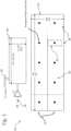
- FIG. 1 is a diagram of a Metamaterial Electronic Steering Array (MESA) transmit-antenna section 10 and a sparse DBF receive-antenna section 12 of a radar system 14, according to an embodiment; the radar system, which is further described below in conjunction with FIGS. 33 - 34 , can include other components not shown in FIG. 1 , such as amplifiers, phase shifters, and other drive circuitry.
- MSA Metamaterial Electronic Steering Array
- the transmit-antenna section 10 can form an entire transmit antenna of the radar system 14, or only a section of the transmit antenna, which may include one or more other sections similar to the section 10; similarly, the receive-antenna section 12 can form an entire receive antenna of the radar system, or only a section of the receive antenna, which may include one or more other sections similar to the section 12.
- the radar system 14 can be configured to operate in any conventional radar frequency band; for example, the radar system can be configured to operate in the W band, which ranges from 75 GHz - 110 GHz, and can be tuned for operation between 76 GHz - 81 GHz.
- FIGS. 35 - 37 an example of the structure and operation of a MESA transmit-antenna section that a designer can use as the transmit-antenna section 10 is described below in conjunctions with FIGS. 35 - 37 .
- ESA electronically steerable/switchable arrays
- Each ESA of the transmit-antenna section 10 (only one ESA shown in FIG. 1 ) includes a respective one analog RF channel input 16, where the RF signal is distributed throughout the ESA area and/or to the sub-elements of the ESA by conventional methods, e.g. , a waveguide, a transmission line, or microstrips.
- Each ESA of the transmit-antenna section 10 also includes one or more control lines 18, either digital or analog, which provide for the electronic control of the transmit-array beam steering.
- This control can be implemented as a single digital line 18, as a collection of digital lines ( e.g ., a digital bus), or as a collection of analog lines.
- control lines 18 are each configured to carry a respective control signal that, depending on the collective state of the control signal(s) over time (e.g ., logic high or logic low, or array of analog voltages), electronically activates a particular configuration of the transmit-array section 10, the configuration describing a particular transmit-beam position, transmit-beam side-lobe level, transmit-beam HPBW, etc.
- multiple ESAs can be configured to work together, each with its own analog-transmit input, by coordinating and synchronizing the transmit-array configurations sent via the respective control lines 18.
- the receive-antenna section 12 includes an array 20 of antenna elements 22, which antenna elements can also be called “antenna segments,” or “segments.”
- the array 20 is segmented into rows 24 and columns 26 of antenna elements 22.
- the array 20 can have six columns 26 and two rows 24 for a total of twelve antenna elements 22.
- the array 20 can have five columns 26 and two rows 24 for a total of ten antenna elements 22.
- each antenna segment 22 is coupled to a single RF receive channel (not shown in FIG. 1 ), such that the receive-antenna section 12 is a digital beam-forming (DBF) array.
- Each receive channel can include a respective amplifier (not shown in FIG. 1 ), a respective down-converter (not shown in FIG. 1 ), a respective Analog-to-Digital Converter (ADC) (not shown in FIG. 1 ), and other RF, analog, and digital components that allow the radar system 14 to measure and digitize the respective signal received by each corresponding antenna element 22.
- these dimensions which define an aperture of the receive-antenna section 12, also affect the minimum Half-Power Beam Width (HPBW) of the receive beam in the AZ and EL dimensions because it is known that the HPBW is inversely proportional to aperture size.
- HPBW Half-Power Beam Width
- an embodiment of the receive-antenna section 12 can generate a receive beam having a minimum HPBW of 5° in the AZ dimension and 10° in the EL dimension.
- the antenna elements 22 within the receive-antenna array 20 can be of any shape and material that provides advantageous antenna-element characteristics, such as, for example, efficiency, gain, bandwidth, HPBW in the AZ and EL dimensions, etc.
- each of the antenna elements 22 can include one or more sub-elements.
- an antenna element 22 can include multiple sub-elements.
- the ESA transmit-antenna section 10 generates a transmit beam with side lobes of relatively low power, and the radar system 14 aligns the receive beam (or receive beams, see below ) within the transmit beam, the redirected transmit energy received by the receive-beam-pattern side lobes is significantly reduced as compared to prior radar systems.
- the radar system 14 can generate, with a "sparse" receive DBF array 20 (i.e ., an array with antenna segments 22 spaced apart by a distance >> ⁇ /2), an effective receive beam (i.e ., the beam resulting from the combination of the transmit and receive beams) having a HPBW that is much narrower than would otherwise be possible with the DBF array alone or paired with the "blast” or "spray" transmission of prior radar systems.
- a "sparse" receive DBF array 20 i.e ., an array with antenna segments 22 spaced apart by a distance >> ⁇ /2
- an effective receive beam i.e ., the beam resulting from the combination of the transmit and receive beams
- the radar system 14 steers a transmit beam in a chosen AZ direction and chosen EL direction using the one or more ESA control lines 18. These chosen directions, constrained by the HPBW of the ESA transmit beam, collectively define a region of illumination within which the receive DBF array 20 can operate with significantly reduced spatial aliasing.
- This area of illumination can be resolved with relatively high Rayleigh resolution by the DFB array 20, and the transmit-antenna section 10 can then illuminate a new area through reconfiguration of the transmit-antenna section 10 and its transmit-beam pattern using the one or more control lines 18.
- a very wide FOV can be covered through the sequential reconfiguration of the transmit-antenna section 10 and its transmit beam pattern from a current illumination area to a new illumination area followed by resolution using the DBF array 20.
- the sequence of this illumination can be ordered (e.g. , raster scan, conical scan), disordered (random, Hadamard), or dynamically or intelligently sequenced (task-able illumination, prioritized FOV time-weighting, etc .) .
- the radar system 14 steers the receive-array beam(s) as follows.
- the radar system 14 operates in a continuous-wave (CW) mode in which it generates the transmit beam and the receive beam simultaneously.
- the radar system 14 also can be configured to operate in a pulsed mode in which it generates one or more "pulses" of the transmit beam, deactivates the transmit beam, activates the receive beam, deactivates the receive beam, and repeats this procedure.
- CW continuous-wave
- the radar system 14 also can be configured to operate in a pulsed mode in which it generates one or more "pulses" of the transmit beam, deactivates the transmit beam, activates the receive beam, deactivates the receive beam, and repeats this procedure.
- the below description presumes that the radar system 14 is operating in a CW mode, the below description is also applicable to the radar system operating in a pulsed mode.
- the radar system 14 simultaneously steers one or more receive beams by selectively applying, to the respective signal received by each antenna segment 22, a respective complex-element weighting, which effectively applies to the respective signal a respective phase shift and a respective gain (the gain can be less than, equal to, or greater than one). That is, the radar system 14 operates the receive-antenna array 20 as a true phased array.
- the radar system 14 can generate the receive beam having a relatively narrow width (e.g ., 2° HPBW in the AZ dimension), and can steer the beam in the AZ dimension in very fine steps (e.g ., 0.1° steps). Because, as described above, the transmit beam super-tends the receive beam, the radar system 14 can steer the receive beam within the Transmit Illumination Solid Angle (TISA), e.g ., the region bounded by the HPBW of the transmit beam. The steps may or may not be such that a receive beam in one position overlaps an adjacent previous position of the receive beam.
- TISA Transmit Illumination Solid Angle
- the radar system 14 simultaneously generates a "bundle" of receive beams that "fit" into the TISA region. For example, if the TISA region is likened to a box of spaghetti, then each strand of spaghetti in the bundle represents a respective receive beam. In this embodiment, because the bundle of receive beams "fills" the TISA, the radar system 14 need not steer the receive beams as described in the above embodiment. That is, in this embodiment, the radar system 14 simultaneously covers, with multiple receive beams, the TISA region, whereas in the above-described embodiment, the radar system sequentially steers a single receive beam from receive-beam position to receive-beam position to cover the TISA region over a period of time.
- the radar system 14 simultaneously generates a bundle of receive beams that 'fit' within the TISA region but do not 'fill' it. Then, the radar system sequentially steers the bundle of receive beams from bundle position to bundle position to cover the TISA region over a period of time. A bundle position may or may not overlap another bundle position.
- the bundle of receive beams includes fewer beams than needed to "fill" the TISA region. Therefore, the radar system 14 can steer the bundle, or one or more receive beams within the bundle, so that at least one receive beam occupies each region within the TISA region before the radar system reconfigures the transmit ESA(s) to steer the transmit beam to another position.
- the radar system 14 is described as generating and steering a single receive beam, it being understood that the description also applies to the radar system simultaneously generating and steering a plurality ( e.g ., a bundle) of receive beams unless otherwise noted.
- FIG. 2 is a diagram of the receive-antenna section 12, the array 20 of antenna elements 22, the phase centers 28 of the antenna elements, and a magnified view of one of the antenna elements 22, according to an embodiment.
- each antenna element 22 includes a micro-strip-fed series subarray of patch sub-elements 30.
- FIG 3 is a plot that depicts the design of the elemental beam pattern 32 (the pattern of the receive beam) in the AZ and EL dimensions.
- the elemental beam pattern 32, and its characteristic HPBW in AZ and EL, define the FOV over which each receive channel, and, therefore, ultimately over which the receive array 20, is able to receive signals.
- the element beam pattern 32 also defines the FOV over which the entire radar system can operate.
- the receive elements 22 are designed with a number and geometry of sub-elements 30 that impart to the receive array 20 a total HPBW of about 90° degrees in the AZ dimension and of about 20° degrees in the EL dimension, allowing for a radar system 14 with a very wide FOV in the AZ dimension and a somewhat constricted FOV in the EL dimension.
- FIG. 4 is a diagram of the area of the receive-antenna section 12, and the receive array 20.
- FIGS. 5 - 6 are plots of the receive-beam patterns 40 and 42 in the AZ dimension and in the EL dimension, respectively, which patterns result from the geometric arrangement of the array 20; the geometric arrangement of the array 20 is typically referred to as the "array-factor.”
- the array-factor beam pattern (the AZ and EL receive-beam patterns viewed together) is affected by the choice of complex weights (amplitude and phase) that are applied to the receive channels, and there are a very large number of possible receive-beam patterns that generate individual beams or bundles of beams as discussed above.
- the AZ and EL receive-beam patterns 40 and 42 in FIGS. 5-6 result only from the geometry of the array 20 ( i.e ., the relative positions of the antenna elements 22), and the choice of the complex receive weights.
- the array-factor receive-beam pattern possesses beam characteristics such as HPBW, beam-angle, and side-lobe-level, which are affected by the choice of the complex receive weights.
- the AZ pattern 40 includes a receive beam 44 and major side lobes 46 and 48.
- the major side lobes 46 and 48 each have a maximum power level greater than one half the power level of ( i.e ., less than 3 dB down from) the power level of the receive beam 44.
- the EL pattern 42 includes the receive beam 44 and major side lobes 50 and 52.
- a goal of a radar-system designer of the radar system 14 is to maximally exclude the side-lobes 46, 48, 50, and 52 from the HPBW regions of the transmit beam in both AZ and EL dimensions by aligning the transmit and receive patterns to maximally exclude side-lobes outside the region of interest.
- FIG. 7 is a diagram that depicts the transmit beam pattern 54, the receive-element beam pattern 56, and the beam pattern in the AZ dimension for the receive array 40 for an embodiment.
- the receive-element beam pattern 56 is due to the arrangement, size, shape, etc. of the antenna sub-elements 30 ( FIG. 2 ).
- a majority of the receive spatial aliasing lies outside the HPBW of the transmit beam pattern 54; therefore, the combination of the transmit-antenna section and the sparse receive-antenna section highly suppresses the receive spatial aliasing in AZ.
- FIG. 8 is a diagram that depicts the transmit beam pattern 58, receive-element beam pattern 60, and the beam pattern of the receive array 42, in the EL dimension, for an embodiment.
- a majority of the receive spatial aliasing lies outside the HPBW of the transmit beam pattern 58; therefore, the combination of the transmit-antenna section and the sparse receive-antenna section highly suppresses the receive spatial aliasing in EL.
- a designer of the radar system 14 may face challenges at reducing the side-lobes of the radar system to a desired level for a particular application.
- the radar-system designer can also leverage the plurality of allowable receive-array 20 geometric configurations.
- the sparsification of the receive array - that is, the separation of array elements by much greater than ⁇ /2 - in addition to offering the benefit of reduced required channel count over a given receive area, also offers additional degrees of freedom in the placement of the receive elements 22.
- a fixed number of receive elements 22 placed over a large area have a number of possible positional configurations in which they do not collide or overlap, the number of such possible positional configurations growing with the area of the receive-antenna array 20.
- FIG. 9 is a diagram of a receive-antenna array section 70, which the can be used in the radar system 14 instead of the receive-antenna array section 20 of FIGS. 1 , 2 , and 4 .
- FIGS. 10- 11 are plots of the beam-and-side-lobe patterns 72 and 74 in the AZ and EL dimensions, respectively, as generated by the antenna section 70 for a single receive beam (if the radar system 14 generates a bundle of receive beams, then these plots are for each receive beam in the bundle).
- the receive-antenna section 70 can generate major receive side lobes that are of lower power than the major receive side lobes 46, 48, 50, and 52 ( FIGS. 5-6 ) generated by the receive antenna 12 ( FIGS. 1 - 2 ), and, therefore, can further decrease aliasing caused by the receive side lobes.
- the receive-antenna section 70 includes ten antenna segments 22 each having six antenna sub-elements 30 (not shown in FIGS. 9 - 11 ).
- the antenna segments 22 are not arranged in the Cartesian vertical columns 26 and horizontal rows 24 of FIG. 1 , but are instead arranged in the pattern shown in FIG. 9 .
- this receive-antenna pattern significantly reduces the levels of the major receive side lobes in both the AZ and EL dimensions, and, therefore, further reduces aliasing, as compared to the receive-antenna section 12 of FIG. 1 .
- the AZ beam pattern 72 of the receive-antenna section 70 includes a receive beam 76 and receive side lobes 78 and 80.
- the side lobes 78 closest to the receive beam 76 each have a maximum power level that is at least 11 dB down from the power level of the receive beam 76. Therefore, even though the side lobes 78 are close to, and may even be within, the HPBW region of the transmit beam 82 in the AZ dimension, the side lobes 78 provide a significant reduction in aliasing compared to the level of aliasing generated by the receive-antenna section 12 of FIG.
- the side lobes 80 provide a significant reduction in aliasing compared to the level of aliasing generated by the receive-antenna section 12 of FIG. 1 because the power level of each of the side lobes 80 is at least 10 dB down from the power levels of the closest side lobe 48 ( FIG. 5 ) generated by the receive-antenna section 12.
- the EL pattern 74 includes the receive beam 76 and side lobes 84 and 86.
- the side lobes 84 closest to the receive beam 76 each have a maximum power level that is at least 10 dB down from the power level of the beam 76. Therefore, even though the side lobes 84 are close to, and may even be within, the HPBW region of the transmit beam 82 in the EL dimension, the side lobes 84 provide a significant reduction in aliasing compared to the level of aliasing generated by the receive-antenna section 12 of FIG. 1 because the power level of each of the side lobes 84 is at least 10 dB down from the power levels of the closest side lobes 50 ( FIG.
- the receive side lobes 86 closest to the receive beam 76 each have a maximum power level that is at least 10 dB down from the power level of the beam 76. Therefore, even though the side lobes 86 are close to, and may even be within, the HPBW region of the transmit beam 82 in the EL dimension, the side lobes 86 provide a significant reduction in aliasing compared to the level of aliasing generated by the receive-antenna section 12 of FIG. 1 because the power level of each of the side lobes 86 is at least 10 dB down from the power levels of the closest side lobes 52 generated by the receive-antenna section 12.
- the number, pattern, and configuration of the antenna segments 22 can be different than as shown in, and as described above in conjunction with, FIGS. 9 - 11 .
- the receive-antenna section 70 can have more or fewer than twelve antenna segments 22, the antenna segments can be arranged differently than shown in FIG. 9 , and each antenna element 22 can have various configurations of sub-elements 30 in terms of the number, location, shapes, and designs of the sub-elements.
- FIG. 12 is a plot of the radar system 14 effective (two-way) AZ beam pattern 90 resulting from the combination of the patterns ( FIGS. 10 - 11 ) of the receive-antenna sub-elements 30 ( FIG. 2 ), the receive-antenna array 20 ( FIG. 9 ), and the transmit-antenna section 10 ( FIG. 1 ), according to one embodiment.
- the receive-array and receive-sub-element beam patterns of the AZ pattern 72 of FIG. 10 are multiplied together and by the transmit beam pattern of the AZ pattern 72 (in the same units of power or magnitude) at each beam angle.
- the effective AZ pattern 90 has significantly lower side-lobe levels, and thus has significantly superior alias rejection, as compared to the AZ receive-array beam pattern, the AZ receive-sub-element beam pattern, or the AZ transmit beam pattern of FIG. 10 .
- FIG. 13 is a plot of the radar system 14 effective (two-way) EL beam pattern 92 resulting from the combination of the patterns ( FIGS. 10 - 11 ) of the receive-antenna sub-elements 30 ( FIG. 2 ), receive array 20 ( FIG. 9 ), and the transmit-antenna section 10 ( FIG. 1 ), according to an embodiment.
- the receive-array and receive-sub-element beam patterns of the EL pattern 74 of FIG. 11 are multiplied together and by the transmit beam pattern of the EL pattern 74 (in the same units of power or magnitude) at each beam angle.
- the effective pattern 92 has significantly lower side-lobe levels, and thus has significantly superior alias rejection, as compared to either the EL receive-array beam pattern, the EL receive-sub-element beam pattern, or the EL transmit-beam pattern of FIG. 11 .
- a technique is described to further reduce aliasing as compared to the above-described embodiments of the radar system 14, according to an embodiment not forming part of the claimed invention. More specifically, a designer of the radar system 14 can alter the design of an ESA transmit antenna to align nulls of the transmit beam-and-side-lobe pattern (in the AZ or EL dimension) with the peaks of the side lobes of the receive beam-and-side-lobe pattern (in the AZ or EL dimension), or to align the side-lobe peaks of the transmit beam-and-side-lobe pattern with the nulls of the receive beam-and-side-lobe pattern. Such alignment effectively causes the transmit nulls/peaks to "cancel" the receive peaks/nulls in the effective beam-and-side-lobe pattern.
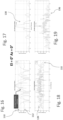
- FIG. 14 is a diagram of a transmit-antenna section 100, which is similar to the transmit-antenna section 10 of FIG. 1 except that the transmit-antenna section 100 has two MESA halves (sub-sections) 106 and 108 separated by a vertical distance ⁇ y between the geometric centers 102 and 104 of the respective MESAs.
- the transmit-antenna section 100 can form a portion of, or an entire, transmit antenna, and ⁇ y can be adjusted to shift the nulls and peaks of the transmit EL beam-and-side-lobe pattern in the EL dimension. This shift is typically symmetrical about the transmit beam.
- increasing ⁇ y causes the nulls and side lobes of the transmit EL beam-and-side-lobe pattern to move closer towards the transmit beam
- decreasing ⁇ y causes the nulls and side lobes of the transmit EL beam-and-side-lobe pattern to move farther away from the transmit beam
- FIG. 15 is a plot of the transmit EL beam-and-side-lobe pattern 110 of the transmit-antenna section 100 ( FIG. 14 ) overlaying the receive EL beam-and-side-lobe pattern 112 of a receive-antenna section that can be similar to the receive-antenna section 70 of FIG. 9 .
- nulls 114 and 116 of the transmit EL pattern 110 are approximately aligned with peaks of side lobes 118 and 120 of the receive EL pattern 112
- nulls 122 and 124 of the receive EL pattern 112 are approximately aligned with the peaks of side lobes 126 and 128 of the transmit EL pattern 110.
- a peak of a side lobe of a receive beam-and-side-lobe pattern coincides with a peak of a side lobe of a transmit beam-and-side-lobe pattern. That is, instead of acting to reduce the magnitude of the effective side lobe, a receive side lobe and a transmit side lobe are additive such that they act to increase the magnitude of the effective side lobe resulting from the combination of the aligned/coinciding transmit and receive side lobes.
- the peak of a transmit side lobe 166 coincides with a peak of a receive side lobe 168 such that the combination of the side lobes 166 and 168 forms a significant effective side lobe 170.
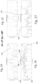
- FIG. 28 is a diagram of a transmit-antenna section 180, according to an embodiment in which the section 180 can form a portion of, or an entire, transmit antenna.
- the transmit-antenna section 180 includes two vertically stacked but separated transmit sub-sections or portions 182 and 184, each of which can be a respective MESA.
- a technique for misaligning, or decorrelating, the peaks of the transmit side lobes and receive side lobes 166 and 168 of FIG. 26 is to shift, or slide, the transmit portion 182 of the transmit-antenna section 180 in the horizontal (AZ) dimension relative to the transmit portion 184.
- the AZ shift of the transmit portion 182 of the transmit antenna section 180 relative to the transmit portion 184 shifts the peak of the transmit side lobe 166 to the left in FIG. 31 such that the peak no longer coincides with the peak of the receive side lobe 168. Furthermore, this shift also reduces the magnitude of the peak of the transmit side lobe 166. Therefore, the magnitude of the effective side lobe 170 formed by the combination of the side lobes 166 and 168 is significantly reduced (by approximately 15 dB) from the magnitude of the side lobe 170 in FIG. 27 .
- the technique of shifting, in AZ (and/or shifting in EL), the transmit portion 182 (106) relative to transmit portion 184 (108) can be applied to decorrelate transmit and receive side lobes at other beam angles in the AZ dimension.
- a designer can select the magnitude and polarity/direction of the shift that yields the best overall side-lobe uncorrelation over all beam angles in the AZ dimension for a particular application.
- Another technique for reducing aliasing due to the receive antenna receiving redirected transmitted energy along one or more receive side lobes is to take advantage of the plurality of complex weights which can be applied to each of the receive channels, noting the fact that multiple choices for the complex weight vector may result in receive arrays with nearly identical main-beams, but with very different side-lobe patterns.
- This technique can be applied to selectively reduce one or more of the receive side lobes by adjusting the complex weighting of each of one or more of the receive antenna segments 22 ( FIG. 4 ) for each of one or more positions of the receive beam (or bundle of receive beams).
- a designer can determine, by simulation or measurement, the major receive side lobes at a receive-beam position, and can determine the best complex weighting for each antenna segment 22 to impart to the receive beam (or bundle of receive beams) the desired beam characteristics (e.g., HPBWs in the AZ and EL dimensions) and to impart to the major receive side lobes the desired side-lobe characteristics (e.g., magnitude, phase).
- the designer can program the radar system 14 to implement these respective determined complex weightings for the antenna segments 22 while the receive beam has the corresponding receive-beam position.
- the designer can repeat this procedure for one or more positions of the receive beam, and can store, e.g., in a look-up table (LUT), the respective complex weightings for each antenna segment 22 for each receive-beam position.
- LUT look-up table
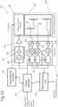
- FIG. 33 is a block diagram of a radar subsystem 210, which includes an antenna group or subsystem 212 including one or more of the transmit and receive antennas 10, 12, 100, and 180 of FIGS. 1 - 2 , 4 , 9 , 14 , and 28 , according to an embodiment in which the radar subsystem 210 can be the same as, or can be substituted for, the radar system 14 of FIG. 1 .
- the radar subsystem 210 includes a transceiver 214, a beam-steering controller 216, a radar processing unit 218, and a master controller 220, which components can be circuits that are hardwired, that are data-stream configurable, that execute software, or that are subcombination or combination of such circuits.
- the antenna subsystem 212 includes a transmit antenna 222, which can include one or more of the transmit-antenna sections 10 ( FIG. 1 ), 100 ( FIG. 14 ), and 180 ( FIG. 28 ), and includes a receive antenna 224, which can include one or more of the receive-antenna sections 12 ( FIGS. 1 - 2 and 4 ) or 70 ( FIG. 9 ).
- the transmit antenna 222 is configured to generate one or more transmit-beam patterns have one or more desired characteristics
- the receive antenna 224 is configured to generate one or more receive-beam patterns having one or more desired characteristics, such that the transmit-beam patterns combine with the respective receive-beam patterns to form spatial filters.
- the transceiver 214 includes transmit circuitry 226 and receive circuitry 228.
- the transmit circuitry 226 includes a voltage-controlled oscillator (VCO) 230, a preamplifier 232, and an amplifier (PA) 234.
- VCO voltage-controlled oscillator
- PA amplifier
- the preamplifier 232 is configured to amplify the VCO signal, and the PA 234 is configured to amplify the signal from the preamplifier.
- the receiver circuitry 228 includes a respective receive channel 236 for each antenna segment 22 of the receive antenna 224.
- the LNA 238 is configured to amplify signals received by the receive antenna 224.
- the mixer 240 is configured to shift the frequencies of the amplified received signals down to a base band, and the ADC 242 is configured to convert the down-shifted analog signals to digital signals for processing by the radar processing unit 220.
- the beam-steering controller 216 is configured to steer the transmitting beams generated by the one or more MESA transmit antennas 222 by generating, on the control lines 18 ( FIG. 1 ) the control signals to the antenna units that compose the one or more transmit antennas as a function of time and main-transmit-beam position. By appropriately generating the control signals, the beam-steering controller 216 is configured to selectively activate and deactivate the antenna elements of the one or more MESA transmit antennas 222 according to selected spatial and temporal patterns. Beam steering of a transmit antenna, such as the one or more MESA transmit antennas 222, is described below in conjunction with FIGS. 35 - 37 .
- the radar processing unit 218 is configured to receive each of the digitized baseband received signals from the receiver 228, and to process the signals to form, and to steer, a receive beam as described above. As described above, the radar processing unit 218 is configured to generate, at any given time, a respective receive beam pattern by amplifying each of the digitized signals with a respective gain, and by shifting each of the digitized signals by a respective phase. By changing the gains and the phase shifts as a function of time, the radar processing unit 218 effectively steers one or more main receive beams of the receive beam pattern.
- the radar processing unit 218 provides the radar data carried by the formed receive beam pattern to a conventional data-processing circuit for further processing for, e.g ., detecting an object along a receive beam, and determining the object's location and velocity.
- data-processing circuit can be configured to analyze the signals from the receiver 228 to, e.g ., identify a detected object and the object's location and velocity, and to determine what action, if any, that a system including, or coupled to, the radar subsystem 210 should take.
- the data-processing circuit is configured to determine what action (e.g ., braking, swerving), if any, the vehicle should take in response to the detected object.
- the radar processing unit 218 can be configured to perform such further processing of the radar data instead of, or in addition to, the data-processing system.
- the master controller 220 is configured to control the transceiver 214, the beam-steering controller 216, and the radar processing unit 218 in response to radar control signals from a radar-system controller (not shown in FIG. 33 .
- the master controller 220 is configured to adjust the frequency of the signal generated by the VCO 230 for, e.g ., environmental conditions such as weather, the average number of objects in the range of the one or more transmit antennas and one or more receive antennas 224, and the average distance of the objects from the one or more transmit and receive antennas, and to conform the transmit signal to spectrum regulations.
- the master controller 220 can be configured to issue, to the beam-steering controller 216 and to the radar processing unit 218, commands that cause the beam-steering controller and the radar processing unit to form transmit and receive beams, respectively, that correspond to the commands.
- any of the system components can store in a memory, and execute, software/program instructions to perform the below-described actions.
- any of the system components, such as the system controller can store, in a memory, a data set, such as firmware, that when loaded configures one or more of the system components to perform the below-described actions.
- any of the system components, such as the system controller can be hardwired to perform the below-described actions.
- the master controller 220 generates a control voltage that causes the VCO 230 to generate a signal at a frequency within a frequency range centered about f 0 .
- f 0 can be in the range of approximately 5 Gigahertz (GHz) - 100 GHz.
- the VCO 230 generates the signal, and the PA 232 and amplifier 234 amplify the signal and provide the amplified signal to the one or more transmit antennas 222.
- the beam-steering controller 216 While the amplifier 234 is coupling the transmit signal to the one or more transmit antennas 222, the beam-steering controller 216, in response to the master controller 220, is generating control signals to the antenna units of the one or more transmit antennas. These control signals cause the one or more transmit antennas to generate and to steer one or more main signal-transmission beams. As described above in conjunction with FIGS. 7-8 , 10 - 27 , and 29 - 32 , the control signals cause the one or more main signal-transmission beams to have desired characteristics, and also cause the transmission side lobes to have desired characteristics such as suitable total side-lobe power and a suitable side-lobe level ( e.g ., between the smallest main signal-transmission beam and the largest side lobe).
- the master controller 220 causes the VCO 230 to cease generating the transmit signal.
- the LNAs 238 respectively amplify the signals received from the respective receive-antenna segments 22.
- the mixers 240 respectively down-convert the amplified signals received from the LNAs 238 from a frequency, e.g ., at or near f 0 , to a baseband frequency.
- the ADCs 242 convert the analog down-converted signals to respective digital signals.
- the master controller 220 generates and sends one or more control signals to the radar processing unit 218.
- control signals cause the radar processing unit 218 to generate and to steer one or more main signal-receive beams by applying, to each of the digitized signals from the receiver circuit 214, a suitable respective gain and phase shift.
- the control signals cause the radar processing unit 218 to generate the one or more main signal-receive beams to have desired characteristics, and also to generate the side lobes to have desired characteristics such as suitable total side-lobe power and a suitable side-lobe level.
- radar processing unit 218, or the data-processing circuit analyzes the amplified and phase-shifted digital signals to obtain information from the signals and to determine what, if anything, should be done in response to the information obtained from the signals.
- the radar subsystem 210 can repeat the above cycle one or more times.
- the radar subsystem 210 can include one or more additional components not described above, and can omit one or more of the above-described components.
- functions or operations attributed to one component of the radar subsystem 210 can be performed by another component of the radar subsystem or by another component outside of the radar subsystem.
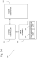
- FIG. 34 is a block diagram of a system, such as a vehicle system 250, which includes the radar subsystem 210 of FIG. 33 , according to an embodiment.
- the vehicle system 250 can be an unmanned aerial vehicle (UAV) such as a drone, or a self-driving car.
- UAV unmanned aerial vehicle
- the vehicle system 250 includes a drive assembly 242 and a system controller 244.
- the drive assembly 252 includes a propulsion unit 256, such as an engine or motor, and a steering unit 258, such as a rudder, flaperon, pitch control, or yaw control (for, e.g ., an UAV or drone), or a steering wheel linked to steerable wheels (for, e.g ., a self-driving car).
- a propulsion unit 256 such as an engine or motor
- a steering unit 258 such as a rudder, flaperon, pitch control, or yaw control (for, e.g ., an UAV or drone), or a steering wheel linked to steerable wheels (for, e.g ., a self-driving car).
- the system controller 254 is configured to control, and to receive information from, the radar subsystem 210 and the drive assembly 252.
- the system controller 254 can be configured to receive locations, sizes, and speeds of nearby objects from the radar subsystem 210, and to receive the speed and traveling direction of the vehicle system 210 from, e.g ., a GPS receiver (not shown in FIG. 34 ) or from a sensor (e.g., accelerometer, also not shown in FIG. 34 ) on board the system 250.
- any of the system components can store in a memory, and execute, software/program instructions to perform the below-described actions.
- any of the system components, such as the system controller 254 can store, in a memory, firmware that when loaded configures one or more of the system components to perform the below-described actions.
- any of the system components, such as the system controller 244, can be circuitry hardwired to perform the below-described actions.
- the system controller 254 activates the radar subsystem 210, which, as described above in conjunction with FIG. 33 , provides to the system controller information regarding one or more objects in the vicinity of the vehicle system 250.
- the radar subsystem can provide information regarding one or more objects (e.g ., birds, aircraft, and other UAVs/drones), in the flight path to the front, sides, and rear of the UAV/drone.
- the radar subsystem 210 can provide information regarding one or more objects (e.g ., other vehicles, debris, pedestrians, bicyclists) in the roadway to the front, sides, and rear of the vehicle system.
- the system controller 254 determines what action, if any, the vehicle system 250 should take in response to the object information.
- the master controller 220 ( FIG. 33 ) of the radar subsystem 210 can make this determination and provide it to the system controller 254.
- the system controller 254 determines that an action should be taken, then the system controller causes the drive assembly 252 to take the determined action. For example, if the system controller 254 or master controller 220 determined that a UAV system 250 is closing on an object in front of the UAV system, then the system controller 254 can control the propulsion unit 256 to reduce air speed. Or, if the system controller 254 or master controller 220 determined that an object in front of a self-driving system 250 is slowing down, then the system controller 254 can control the propulsion unit 256 to reduce engine speed and to apply a brake.
- the system controller 254 can control the propulsion unit 256 to reduce engine speed and, for a self-driving vehicle, to apply a brake, and can control the steering unit 258 to maneuver the vehicle system away from or around the object.
- an object e.g ., another UAV/drone, a bird, a child who ran in front of the vehicle system 250
- the system controller 254 can control the propulsion unit 256 to reduce engine speed and, for a self-driving vehicle, to apply a brake, and can control the steering unit 258 to maneuver the vehicle system away from or around the object.
- the vehicle system 250 can include one or more additional components not described above, and can omit one or more of the above-described components.
- the vehicle system 250 can be a vehicle system other than a UAV, drone, or self-driving car.
- Other examples of the vehicle system 250 include a watercraft, a motor cycle, a car that is not self-driving, and a space craft.
- a system including the radar subsystem 210 can be other than a vehicle system.
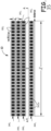
- FIG. 35 is a plan view of the transmit-antenna section 10 of FIG. 1 in which the transmit-antenna section is a holographic-aperture antenna section having multiple waveguides 260 1 - 260 n and corresponding conductive antenna elements 262 1 - 262 n , according to an embodiment.
- the waveguides 260 are conventional rectangular-strip transmission-line waveguides, only the top portions of which are visible in FIG. 35 , and are approximately parallel to one another.
- the antenna elements 262 1 - 262 n are arranged over the waveguides 260 in respective one-dimensional arrays.
- the antenna elements 262 1 are arranged in a one-dimensional array over the waveguide 260 1
- the antenna elements 262 2 are arranged in a one-dimensional array over the waveguide 260 2
- so on the waveguides 260 are spaced apart from one another, on longitudinal center, by a distance d 1 ⁇ ⁇ 0 /2
- the antenna elements 262 within each one-dimensional array are spaced apart from one another by a distance d 2 ⁇ ⁇ 0 .
- each of the waveguides 260 has approximately the same length l of between approximately 3 ⁇ 0 - 20 ⁇ 0 , or the length l can be even longer than 20 ⁇ 0 .
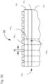
- FIG. 36 is a cut-away side view of the transmit-antenna section 10 of FIG. 35 , taken along line A-A of FIG. 35 , according to an embodiment.
- the waveguide 260 3 and the corresponding antenna elements 262 3 are shown in FIG. 36 , the following discussion also applies to the other waveguides and antenna elements.
- the transmit-antenna section 10 includes a conductive plane, such as a ground plane, disposed beneath the dielectric layer 274. In operation, a signal guided by the waveguide 260 3 propagates along the dielectric layer 274 between the conductive strip 272 3 and the ground plane.
- the transmit-antenna section 10 can include a single coupling layer 270 and a single dielectric layer 274 common to all of the waveguides 260, the antenna section includes separate conductive strips 272, one strip per waveguide. It is these strips 272, and the corresponding antenna elements 262, that are spaced apart by the distance d 1 (see FIG. 35 ).
- the antenna element 262 3,5 and the coupling region 276 3,5 of the layer 270 form an antenna unit 278 3,5 of the transmit antenna-section 10.
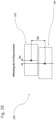
- FIG. 37 is a side view and electrical diagram of the antenna unit 278 3,5 of FIG. 36 , and the portion of the conductive strip 272 3 of the waveguide 260 3 corresponding to the antenna unit, according to an embodiment.
- the coupling region 276 3,5 can be modeled as a lumped adjustable-impedance element 280 3,5 , which is electrically coupled between the conductive strip 272 3 and the antenna element 262 3,5 .
- a conductive control line 282 3,5 is directly coupled to the lumped element 280 3,5 , or is indirectly coupled to the lumped element via the conductive antenna element 262 3,5 as shown.
- a controller e.g ., the master controller 220 of FIG.
- a low-pass filter 284 3,5 can be serially coupled between the lumped element 280 3,5 and the controller to uncouple, from the controller, high-frequency energy from the signal propagating along the waveguide 260 3 .
- the portion of the conductive strip 272 3 corresponding to the antenna unit 278 3,5 includes a gap 38 3,5 , which can be filled with that same material that forms the coupling layer 270, and which is configured to couple the signal propagating along the waveguide 260 3 to the antenna unit.
- the coupling region 276 3,5 presents a large impedance to the gap 286 3,5 , and thus blocks the signal propagating along the waveguide 260 3 from coupling to, and exciting, the antenna element 262 3,5 . Therefore, the antenna element 262 3,5 radiates little or no energy.
- the coupling region 276 3,5 presents a small impedance to the gap 286 3,5 , and thus couples the signal propagating along the waveguide 260 3 to the antenna element 262 3,5 such that the signal excites the antenna element. Therefore, the excited antenna element 262 3,5 radiates energy at the same frequency or frequencies as the frequency or frequencies of the signal propagating along the waveguide 260 3 .
- the coupling region 276 3,5 is configured to form, together with the antenna element 262 3,5 , a series-resonant circuit having a resonant frequency of approximately f 0 .
- a series-resonant circuit has a low impedance, ideally zero impedance. Because the signal propagating along the waveguide 260 3 has a frequency of approximately f 0 , the region 276 3,5 , when the lumped element 280 3,5 is active, presents a low impedance to the signal.
- the lumped element 280 3,5 can be, or can include, a semiconductor device, such as a PN-junction diode, field-effect transistor (FET), or other device that, when activated, alters the impedance of the coupling region 26 3,5 such that the coupling region forms, at f 0 , a series-resonant circuit with the antenna element 262 3,5 , or between the conductive strip 272 3 and the antenna element.
- a semiconductor device such as a PN-junction diode, field-effect transistor (FET), or other device that, when activated, alters the impedance of the coupling region 26 3,5 such that the coupling region forms, at f 0 , a series-resonant circuit with the antenna element 262 3,5 , or between the conductive strip 272 3 and the antenna element.
- FET field-effect transistor
- all of the other antenna units 278 of the transmit-antenna section 10 can have the same structure, and can operate in the same manner, as the antenna unit 278 3,5 .
- each of the subsections 106 and 108 of the transmit-antenna section 100 of FIG. 14 can be similar in structure and operation to the transmit-antenna section 10.
- any described component or operation may be implemented/performed in hardware, software, firmware, or a combination of any two or more of hardware, software, and firmware.
- one or more components of a described apparatus or system may have been omitted from the description for clarity or another reason.
- one or more components of a described apparatus or system that have been included in the description may be omitted from the apparatus or system.
Landscapes
- Engineering & Computer Science (AREA)
- Radar, Positioning & Navigation (AREA)
- Remote Sensing (AREA)
- Physics & Mathematics (AREA)
- Computer Networks & Wireless Communication (AREA)
- General Physics & Mathematics (AREA)
- Electromagnetism (AREA)
- Computer Security & Cryptography (AREA)
- Variable-Direction Aerials And Aerial Arrays (AREA)
- Radar Systems Or Details Thereof (AREA)
- Details Of Aerials (AREA)
Applications Claiming Priority (2)
| Application Number | Priority Date | Filing Date | Title |
|---|---|---|---|
| US201662430306P | 2016-12-05 | 2016-12-05 | |
| PCT/US2017/064754 WO2018106720A1 (en) | 2016-12-05 | 2017-12-05 | Antenna subsystem with analog beam-steering transmit array and digital beam-forming receive array |
Publications (3)
| Publication Number | Publication Date |
|---|---|
| EP3545334A1 EP3545334A1 (en) | 2019-10-02 |
| EP3545334B1 true EP3545334B1 (en) | 2024-12-04 |
| EP3545334C0 EP3545334C0 (en) | 2024-12-04 |
Family
ID=60703232
Family Applications (1)
| Application Number | Title | Priority Date | Filing Date |
|---|---|---|---|
| EP17817620.2A Active EP3545334B1 (en) | 2016-12-05 | 2017-12-05 | Antenna subsystem with analog beam-steering transmit array and digital beam-forming receive array |
Country Status (6)
| Country | Link |
|---|---|
| US (1) | US10684354B2 (pl) |
| EP (1) | EP3545334B1 (pl) |
| JP (3) | JP7241016B2 (pl) |
| ES (1) | ES2998472T3 (pl) |
| PL (1) | PL3545334T3 (pl) |
| WO (1) | WO2018106720A1 (pl) |
Families Citing this family (24)
| Publication number | Priority date | Publication date | Assignee | Title |
|---|---|---|---|---|
| US10083614B2 (en) | 2015-10-22 | 2018-09-25 | Drone Traffic, Llc | Drone alerting and reporting system |
| US11879989B2 (en) | 2016-12-05 | 2024-01-23 | Echodyne Corp. | Antenna subsystem with analog beam-steering transmit array and sparse hybrid analog and digital beam-steering receive array |
| US11437731B2 (en) * | 2017-09-13 | 2022-09-06 | Metawave Corporation | Method and apparatus for a passive radiating and feed structure |
| US11404794B2 (en) * | 2018-06-26 | 2022-08-02 | Metawave Corporation | Multi-layer, multi-steering antenna array for millimeter wave applications |
| US10386462B1 (en) * | 2018-10-02 | 2019-08-20 | Oculii Corp. | Systems and methods for stereo radar tracking |
| CN109599680B (zh) * | 2018-10-29 | 2021-07-20 | 福瑞泰克智能系统有限公司 | 一种稀疏阵列mimo天线 |
| JP7573926B2 (ja) * | 2019-03-20 | 2024-10-28 | パナソニックオートモーティブシステムズ株式会社 | レーダ装置及び送受信アレーアンテナ |
| CN110137672B (zh) * | 2019-04-01 | 2020-07-07 | 华为技术有限公司 | 一种集边射和端射于一体的波束扫描天线阵列 |
| TWI726791B (zh) | 2019-08-14 | 2021-05-01 | 創未來科技股份有限公司 | 訊號除頻器、訊號分佈系統與其相關方法 |
| NL2023707B1 (en) | 2019-08-26 | 2021-04-13 | Nxp Bv | Mimo radar system |
| US11422226B2 (en) * | 2019-12-10 | 2022-08-23 | Raytheon Company | Systems and methods for multipath beam nulling |
| EP3809160A1 (en) * | 2019-10-18 | 2021-04-21 | Furuno Electric Company Limited | Apparatus and method for detecting objects in water bodies |
| US11435438B2 (en) * | 2019-12-30 | 2022-09-06 | Woven Planet North America, Inc. | Dynamic sparse radar array for scenarios |
| US11555889B2 (en) * | 2020-04-28 | 2023-01-17 | Bae Systems Information And Electronic Systems Integration Inc. | Interferometrics for mesa radar |
| FR3109825B1 (fr) * | 2020-04-29 | 2022-05-06 | Thales Sa | Procédé d’imagerie radar, et radar mettant en œuvre un tel procédé. |
| FR3116127B1 (fr) * | 2020-11-12 | 2022-11-11 | Thales Sa | Système radar d'imagerie à entrées et sorties multiples de type MIMO. |
| SE545379C2 (en) * | 2020-11-26 | 2023-07-25 | Saab Ab | A multiple-input multiple-output radar system |
| EP4096020A1 (en) | 2021-05-25 | 2022-11-30 | Veoneer Sweden AB | Vehicle radar sensor unit with increased vertical resolution |
| US12210115B2 (en) * | 2022-04-05 | 2025-01-28 | Honeywell International Inc. | High isolation between transmit and receive antenna in FMCW radars |
| CN115616487A (zh) * | 2022-09-16 | 2023-01-17 | 杭州腓腓科技有限公司 | 基于全息波束成形的雷达通信一体化装置 |
| CN115825900B (zh) * | 2023-01-10 | 2025-08-22 | 中国人民解放军63892部队 | 基于天线性能等效反演的相控阵雷达射频注入式仿真方法 |
| US20250164605A1 (en) * | 2023-11-21 | 2025-05-22 | Waymo Llc | Methods and Systems for Transmit Beam Agnostic Radar Calibration |
| CN117423994B (zh) * | 2023-12-15 | 2024-07-19 | 北京木牛领航科技有限公司 | 一种满足特定空域覆盖需求的毫米波雷达天线 |
| CN118777990B (zh) * | 2024-07-08 | 2026-04-14 | 西安电子科技大学 | 基于电磁超材料的阵列雷达空时编码数字调控抗干扰方法 |
Citations (8)
| Publication number | Priority date | Publication date | Assignee | Title |
|---|---|---|---|---|
| US20070273603A1 (en) * | 2003-11-27 | 2007-11-29 | Bengt Svensson | Scanable Sparse Antenna Array |
| US20110063158A1 (en) * | 2009-09-17 | 2011-03-17 | Denso Corporation | Array antenna apparatus and radar apparatus |
| US20120194399A1 (en) * | 2010-10-15 | 2012-08-02 | Adam Bily | Surface scattering antennas |
| US20130088393A1 (en) * | 2011-10-06 | 2013-04-11 | Toyota Motor Engineering & Manufacturing North America, Inc. | Transmit and receive phased array for automotive radar improvement |
| US20140022109A1 (en) * | 2012-07-23 | 2014-01-23 | Toyota Motor Engineering & Manufacturing North America, Inc. | Radar field of view expansion with phased array transceiver |
| US20150288063A1 (en) * | 2014-04-07 | 2015-10-08 | Mikala C. Johnson | Beam shaping for reconfigurable holographic antennas |
| US20160172767A1 (en) * | 2014-12-12 | 2016-06-16 | The Boeing Company | Congruent non-uniform antenna arrays |
| US20160285172A1 (en) * | 2015-03-25 | 2016-09-29 | Panasonic Corporation | Radar device |
Family Cites Families (33)
| Publication number | Priority date | Publication date | Assignee | Title |
|---|---|---|---|---|
| US2981949A (en) | 1956-09-04 | 1961-04-25 | Hughes Aircraft Co | Flush-mounted plural waveguide slot antenna |
| US3270336A (en) * | 1963-06-25 | 1966-08-30 | Martin Marietta Corp | Eliminating multiple responses in a grating lobe antenna array |
| US3852754A (en) * | 1971-09-21 | 1974-12-03 | Litton Systems Inc | Binary beam system |
| US3842417A (en) * | 1972-02-14 | 1974-10-15 | Hughes Aircraft Co | Bistatic radar system |
| DE2306407C3 (de) * | 1972-02-14 | 1981-11-12 | Hughes Aircraft Co., Culver City, Calif. | Antennensystem hoher Winkelauflösung für Radargeräte mit getrennten Sende- und Empfangsantennen |
| US3825928A (en) * | 1972-02-14 | 1974-07-23 | Hughes Aircraft Co | High resolution bistatic radar system |
| US4223315A (en) * | 1975-11-03 | 1980-09-16 | Andrew Alford | Stacked arrays for broadcasting elliptically polarized waves |
| US4870424A (en) | 1982-10-25 | 1989-09-26 | Ball Corporation | Method and apparatus for reducing unwanted r.f. signal antenna reception/transmission |
| US5781157A (en) | 1996-08-05 | 1998-07-14 | Mcdonnell Douglas Corporation | Multiple beam radar system with enhanced sidelobe supression |
| JPH11231040A (ja) * | 1998-02-12 | 1999-08-27 | Toyota Motor Corp | レーダ装置 |
| US6901062B2 (en) * | 1999-12-01 | 2005-05-31 | Kathrein-Werke Kg | Adaptive antenna array wireless data access point |
| JP4147447B2 (ja) * | 2001-09-27 | 2008-09-10 | 富士通株式会社 | アレーアンテナ装置及びグレーティング抑圧方法 |
| DE60232609D1 (de) | 2002-08-30 | 2009-07-23 | Ericsson Telefon Ab L M | Verringerung von nah-mehrdeutigkeiten |
| WO2005062426A1 (en) * | 2003-12-22 | 2005-07-07 | Telefonaktiebolaget Lm Ericsson (Publ) | Method and system of communications |
| JP2005195490A (ja) * | 2004-01-08 | 2005-07-21 | Mitsubishi Electric Corp | レーダ装置 |
| JP4545460B2 (ja) * | 2004-03-10 | 2010-09-15 | 三菱電機株式会社 | レーダ装置およびアンテナ装置 |
| JP4541120B2 (ja) * | 2004-12-09 | 2010-09-08 | 三菱電機株式会社 | レーダ装置 |
| US7081851B1 (en) | 2005-02-10 | 2006-07-25 | Raytheon Company | Overlapping subarray architecture |
| CN103441339B (zh) * | 2006-04-27 | 2016-01-13 | 泰科电子服务有限责任公司 | 异向材料天线设备 |
| WO2008053685A1 (en) * | 2006-11-01 | 2008-05-08 | Murata Manufacturing Co., Ltd. | Radar target detecting method and radar device using the target detection method |
| JP5130079B2 (ja) * | 2007-02-28 | 2013-01-30 | 株式会社デンソーアイティーラボラトリ | 電子走査式レーダ装置及び受信用アレーアンテナ |
| US8362967B2 (en) * | 2008-10-15 | 2013-01-29 | Powerwave Technologies, Inc. | Low power multi-beam active array for cellular communications |
| US8742982B2 (en) * | 2010-03-30 | 2014-06-03 | Sony Corporation | Indirect radar holography apparatus and corresponding method |
| JP5093298B2 (ja) * | 2010-06-04 | 2012-12-12 | 株式会社デンソー | 方位検出装置 |
| US9871293B2 (en) | 2010-11-03 | 2018-01-16 | The Boeing Company | Two-dimensionally electronically-steerable artificial impedance surface antenna |
| US9385435B2 (en) | 2013-03-15 | 2016-07-05 | The Invention Science Fund I, Llc | Surface scattering antenna improvements |
| US9923271B2 (en) | 2013-10-21 | 2018-03-20 | Elwha Llc | Antenna system having at least two apertures facilitating reduction of interfering signals |
| US9261592B2 (en) * | 2014-01-13 | 2016-02-16 | Mitsubishi Electric Research Laboratories, Inc. | Method and system for through-the-wall imaging using compressive sensing and MIMO antenna arrays |
| US9853361B2 (en) | 2014-05-02 | 2017-12-26 | The Invention Science Fund I Llc | Surface scattering antennas with lumped elements |
| US9545923B2 (en) * | 2014-07-14 | 2017-01-17 | Palo Alto Research Center Incorporated | Metamaterial-based object-detection system |
| US10263331B2 (en) | 2014-10-06 | 2019-04-16 | Kymeta Corporation | Device, system and method to mitigate side lobes with an antenna array |
| JP6801214B2 (ja) * | 2016-04-14 | 2020-12-16 | ソニー株式会社 | Mimoレーダ装置及び車両 |
| PL3488260T3 (pl) | 2016-07-21 | 2025-01-13 | Echodyne Corp. | Szybkie wzory wiązki |
-
2017
- 2017-12-05 PL PL17817620.2T patent/PL3545334T3/pl unknown
- 2017-12-05 JP JP2019529883A patent/JP7241016B2/ja active Active
- 2017-12-05 EP EP17817620.2A patent/EP3545334B1/en active Active
- 2017-12-05 US US15/832,568 patent/US10684354B2/en active Active
- 2017-12-05 ES ES17817620T patent/ES2998472T3/es active Active
- 2017-12-05 WO PCT/US2017/064754 patent/WO2018106720A1/en not_active Ceased
-
2022
- 2022-11-01 JP JP2022175409A patent/JP2023022006A/ja active Pending
-
2024
- 2024-07-11 JP JP2024111441A patent/JP2024156694A/ja active Pending
Patent Citations (8)
| Publication number | Priority date | Publication date | Assignee | Title |
|---|---|---|---|---|
| US20070273603A1 (en) * | 2003-11-27 | 2007-11-29 | Bengt Svensson | Scanable Sparse Antenna Array |
| US20110063158A1 (en) * | 2009-09-17 | 2011-03-17 | Denso Corporation | Array antenna apparatus and radar apparatus |
| US20120194399A1 (en) * | 2010-10-15 | 2012-08-02 | Adam Bily | Surface scattering antennas |
| US20130088393A1 (en) * | 2011-10-06 | 2013-04-11 | Toyota Motor Engineering & Manufacturing North America, Inc. | Transmit and receive phased array for automotive radar improvement |
| US20140022109A1 (en) * | 2012-07-23 | 2014-01-23 | Toyota Motor Engineering & Manufacturing North America, Inc. | Radar field of view expansion with phased array transceiver |
| US20150288063A1 (en) * | 2014-04-07 | 2015-10-08 | Mikala C. Johnson | Beam shaping for reconfigurable holographic antennas |
| US20160172767A1 (en) * | 2014-12-12 | 2016-06-16 | The Boeing Company | Congruent non-uniform antenna arrays |
| US20160285172A1 (en) * | 2015-03-25 | 2016-09-29 | Panasonic Corporation | Radar device |
Also Published As
| Publication number | Publication date |
|---|---|
| JP2024156694A (ja) | 2024-11-06 |
| US20180156891A1 (en) | 2018-06-07 |
| WO2018106720A1 (en) | 2018-06-14 |
| EP3545334C0 (en) | 2024-12-04 |
| EP3545334A1 (en) | 2019-10-02 |
| JP2020501146A (ja) | 2020-01-16 |
| ES2998472T3 (en) | 2025-02-20 |
| PL3545334T3 (pl) | 2025-06-02 |
| JP2023022006A (ja) | 2023-02-14 |
| US10684354B2 (en) | 2020-06-16 |
| JP7241016B2 (ja) | 2023-03-16 |
Similar Documents
| Publication | Publication Date | Title |
|---|---|---|
| EP3545334B1 (en) | Antenna subsystem with analog beam-steering transmit array and digital beam-forming receive array | |
| US12298428B2 (en) | Antenna subsystem with analog beam-steering transmit array and sparse hybrid analog and digital beam-steering receive array | |
| US11163037B2 (en) | Antenna array that includes analog beam-steering transmit antenna and analog beam-steering receive antenna arranged orthogonally to the transmit antenna, and related subsystem, system, and method | |
| EP3679625B1 (en) | Antenna array having a different beam-steering resolution in one dimension than in another dimension | |
| US11211716B2 (en) | Antenna having increased side-lobe suppression and improved side-lobe level | |
| US6714163B2 (en) | Structurally-integrated, space-fed phased array antenna system for use on an aircraft | |
| JP2021511726A (ja) | 同調可能広帯域幅ラジアルラインスロットアンテナ | |
| EP3956945B1 (en) | Phase-selectable antenna unit and related antenna, subsystem, system, and method | |
| JP2024512974A (ja) | デュアルビーム機能を備えたセンターフィード型とエッジフィード型のハイブリッドメタサーフェスアンテナ | |
| US20210210858A1 (en) | Method and apparatus for an active radiating and feed structure | |
| US11749883B2 (en) | Waveguide with radiation slots and parasitic elements for asymmetrical coverage | |
| US20190081395A1 (en) | Method and apparatus for an active radiating and feed structure | |
| CA2489897C (en) | Common aperture antenna | |
| EP3830897B1 (en) | Conformal antenna |
Legal Events
| Date | Code | Title | Description |
|---|---|---|---|
| STAA | Information on the status of an ep patent application or granted ep patent |
Free format text: STATUS: UNKNOWN |
|
| STAA | Information on the status of an ep patent application or granted ep patent |
Free format text: STATUS: THE INTERNATIONAL PUBLICATION HAS BEEN MADE |
|
| PUAI | Public reference made under article 153(3) epc to a published international application that has entered the european phase |
Free format text: ORIGINAL CODE: 0009012 |
|
| STAA | Information on the status of an ep patent application or granted ep patent |
Free format text: STATUS: REQUEST FOR EXAMINATION WAS MADE |
|
| 17P | Request for examination filed |
Effective date: 20190628 |
|
| AK | Designated contracting states |
Kind code of ref document: A1 Designated state(s): AL AT BE BG CH CY CZ DE DK EE ES FI FR GB GR HR HU IE IS IT LI LT LU LV MC MK MT NL NO PL PT RO RS SE SI SK SM TR |
|
| AX | Request for extension of the european patent |
Extension state: BA ME |
|
| RIN1 | Information on inventor provided before grant (corrected) |
Inventor name: BRUNE, NICHOLAS K. Inventor name: TZANIDIS, IOANNIS Inventor name: PERQUE, MILTON Inventor name: RENNEBERG, CHARLES A. Inventor name: HUNT, JOHN DESMOND Inventor name: LANDY, NATHAN INGLE Inventor name: WORL, ROBERT TILMAN Inventor name: HULL, JONATHAN R. Inventor name: TEESLINK, TARRON Inventor name: LAMBRECHT, CHRISTOPHER L. Inventor name: BILY, ADAM Inventor name: SIKES, BENJAMIN Inventor name: CHATNI, MUHAMMAD RAMEEZ Inventor name: DRISCOLL, TOM |
|
| RIN1 | Information on inventor provided before grant (corrected) |
Inventor name: SIKES, BENJAMIN Inventor name: BRUNE, NICHOLAS K. Inventor name: DRISCOLL, TOM Inventor name: LANDY, NATHAN INGLE Inventor name: HULL, JONATHAN R. Inventor name: HUNT, JOHN DESMOND Inventor name: BILY, ADAM Inventor name: PERQUE, MILTON Inventor name: LAMBRECHT, CHRISTOPHER L. Inventor name: TEESLINK, TARRON Inventor name: RENNEBERG, CHARLES A. Inventor name: CHATNI, MUHAMMAD RAMEEZ Inventor name: TZANIDIS, IOANNIS Inventor name: WORL, ROBERT TILMAN |
|
| DAV | Request for validation of the european patent (deleted) | ||
| DAX | Request for extension of the european patent (deleted) | ||
| STAA | Information on the status of an ep patent application or granted ep patent |
Free format text: STATUS: EXAMINATION IS IN PROGRESS |
|
| 17Q | First examination report despatched |
Effective date: 20210609 |
|
| P01 | Opt-out of the competence of the unified patent court (upc) registered |
Effective date: 20230508 |
|
| GRAP | Despatch of communication of intention to grant a patent |
Free format text: ORIGINAL CODE: EPIDOSNIGR1 |
|
| STAA | Information on the status of an ep patent application or granted ep patent |
Free format text: STATUS: GRANT OF PATENT IS INTENDED |
|
| INTG | Intention to grant announced |
Effective date: 20240702 |
|
| RAP3 | Party data changed (applicant data changed or rights of an application transferred) |
Owner name: ECHODYNE CORP. |
|
| GRAS | Grant fee paid |
Free format text: ORIGINAL CODE: EPIDOSNIGR3 |
|
| GRAA | (expected) grant |
Free format text: ORIGINAL CODE: 0009210 |
|
| STAA | Information on the status of an ep patent application or granted ep patent |
Free format text: STATUS: THE PATENT HAS BEEN GRANTED |
|
| AK | Designated contracting states |
Kind code of ref document: B1 Designated state(s): AL AT BE BG CH CY CZ DE DK EE ES FI FR GB GR HR HU IE IS IT LI LT LU LV MC MK MT NL NO PL PT RO RS SE SI SK SM TR |
|
| REG | Reference to a national code |
Ref country code: GB Ref legal event code: FG4D |
|
| REG | Reference to a national code |
Ref country code: CH Ref legal event code: EP |
|
| REG | Reference to a national code |
Ref country code: DE Ref legal event code: R096 Ref document number: 602017086573 Country of ref document: DE |
|
| REG | Reference to a national code |
Ref country code: IE Ref legal event code: FG4D |
|
| U01 | Request for unitary effect filed |
Effective date: 20250102 |
|
| U07 | Unitary effect registered |
Designated state(s): AT BE BG DE DK EE FI FR IT LT LU LV MT NL PT RO SE SI Effective date: 20250114 |
|
| P04 | Withdrawal of opt-out of the competence of the unified patent court (upc) registered |
Free format text: CASE NUMBER: APP_1578/2025 Effective date: 20250110 |
|
| REG | Reference to a national code |
Ref country code: ES Ref legal event code: FG2A Ref document number: 2998472 Country of ref document: ES Kind code of ref document: T3 Effective date: 20250220 |
|
| PG25 | Lapsed in a contracting state [announced via postgrant information from national office to epo] |
Ref country code: HR Free format text: LAPSE BECAUSE OF FAILURE TO SUBMIT A TRANSLATION OF THE DESCRIPTION OR TO PAY THE FEE WITHIN THE PRESCRIBED TIME-LIMIT Effective date: 20241204 |
|
| PG25 | Lapsed in a contracting state [announced via postgrant information from national office to epo] |
Ref country code: GR Free format text: LAPSE BECAUSE OF FAILURE TO SUBMIT A TRANSLATION OF THE DESCRIPTION OR TO PAY THE FEE WITHIN THE PRESCRIBED TIME-LIMIT Effective date: 20250305 |
|
| PG25 | Lapsed in a contracting state [announced via postgrant information from national office to epo] |
Ref country code: RS Free format text: LAPSE BECAUSE OF FAILURE TO SUBMIT A TRANSLATION OF THE DESCRIPTION OR TO PAY THE FEE WITHIN THE PRESCRIBED TIME-LIMIT Effective date: 20250304 |
|
| PG25 | Lapsed in a contracting state [announced via postgrant information from national office to epo] |
Ref country code: SM Free format text: LAPSE BECAUSE OF FAILURE TO SUBMIT A TRANSLATION OF THE DESCRIPTION OR TO PAY THE FEE WITHIN THE PRESCRIBED TIME-LIMIT Effective date: 20241204 |
|
| PG25 | Lapsed in a contracting state [announced via postgrant information from national office to epo] |
Ref country code: IS Free format text: LAPSE BECAUSE OF FAILURE TO SUBMIT A TRANSLATION OF THE DESCRIPTION OR TO PAY THE FEE WITHIN THE PRESCRIBED TIME-LIMIT Effective date: 20250404 |
|
| PG25 | Lapsed in a contracting state [announced via postgrant information from national office to epo] |
Ref country code: SK Free format text: LAPSE BECAUSE OF FAILURE TO SUBMIT A TRANSLATION OF THE DESCRIPTION OR TO PAY THE FEE WITHIN THE PRESCRIBED TIME-LIMIT Effective date: 20241204 |
|
| PG25 | Lapsed in a contracting state [announced via postgrant information from national office to epo] |
Ref country code: CZ Free format text: LAPSE BECAUSE OF FAILURE TO SUBMIT A TRANSLATION OF THE DESCRIPTION OR TO PAY THE FEE WITHIN THE PRESCRIBED TIME-LIMIT Effective date: 20241204 |
|
| U21 | Renewal fee for the european patent with unitary effect paid with additional fee |
Year of fee payment: 8 Effective date: 20250621 |
|
| REG | Reference to a national code |
Ref country code: CH Ref legal event code: PL |
|
| PG25 | Lapsed in a contracting state [announced via postgrant information from national office to epo] |
Ref country code: MC Free format text: LAPSE BECAUSE OF FAILURE TO SUBMIT A TRANSLATION OF THE DESCRIPTION OR TO PAY THE FEE WITHIN THE PRESCRIBED TIME-LIMIT Effective date: 20241204 |
|
| PLBE | No opposition filed within time limit |
Free format text: ORIGINAL CODE: 0009261 |
|
| STAA | Information on the status of an ep patent application or granted ep patent |
Free format text: STATUS: NO OPPOSITION FILED WITHIN TIME LIMIT |
|
| PG25 | Lapsed in a contracting state [announced via postgrant information from national office to epo] |
Ref country code: CH Free format text: LAPSE BECAUSE OF NON-PAYMENT OF DUE FEES Effective date: 20241231 |
|
| PG25 | Lapsed in a contracting state [announced via postgrant information from national office to epo] |
Ref country code: IE Free format text: LAPSE BECAUSE OF NON-PAYMENT OF DUE FEES Effective date: 20241205 |
|
| 26N | No opposition filed |
Effective date: 20250905 |
|
| U20 | Renewal fee for the european patent with unitary effect paid |
Year of fee payment: 9 Effective date: 20251110 |
|
| PGFP | Annual fee paid to national office [announced via postgrant information from national office to epo] |
Ref country code: GB Payment date: 20251001 Year of fee payment: 9 |
|
| PGFP | Annual fee paid to national office [announced via postgrant information from national office to epo] |
Ref country code: NO Payment date: 20251210 Year of fee payment: 9 |
|
| PGFP | Annual fee paid to national office [announced via postgrant information from national office to epo] |
Ref country code: TR Payment date: 20251128 Year of fee payment: 9 |
|
| PGFP | Annual fee paid to national office [announced via postgrant information from national office to epo] |
Ref country code: PL Payment date: 20251003 Year of fee payment: 9 |
|
| PG25 | Lapsed in a contracting state [announced via postgrant information from national office to epo] |
Ref country code: CY Free format text: LAPSE BECAUSE OF FAILURE TO SUBMIT A TRANSLATION OF THE DESCRIPTION OR TO PAY THE FEE WITHIN THE PRESCRIBED TIME-LIMIT; INVALID AB INITIO Effective date: 20171205 |
|
| PGFP | Annual fee paid to national office [announced via postgrant information from national office to epo] |
Ref country code: ES Payment date: 20260112 Year of fee payment: 9 |