EP3545201B1 - Ensemble de fixation et système de barrière - Google Patents
Ensemble de fixation et système de barrière Download PDFInfo
- Publication number
- EP3545201B1 EP3545201B1 EP17874073.4A EP17874073A EP3545201B1 EP 3545201 B1 EP3545201 B1 EP 3545201B1 EP 17874073 A EP17874073 A EP 17874073A EP 3545201 B1 EP3545201 B1 EP 3545201B1
- Authority
- EP
- European Patent Office
- Prior art keywords
- tie
- clamping block
- panel
- saddle
- fastener assembly
- Prior art date
- Legal status (The legal status is an assumption and is not a legal conclusion. Google has not performed a legal analysis and makes no representation as to the accuracy of the status listed.)
- Active
Links
Images


Classifications
-
- E—FIXED CONSTRUCTIONS
- E04—BUILDING
- E04F—FINISHING WORK ON BUILDINGS, e.g. STAIRS, FLOORS
- E04F11/00—Stairways, ramps, or like structures; Balustrades; Handrails
- E04F11/18—Balustrades; Handrails
- E04F11/181—Balustrades
- E04F11/1851—Filling panels, e.g. concrete, sheet metal panels
- E04F11/1855—Wire mesh panels
-
- E—FIXED CONSTRUCTIONS
- E04—BUILDING
- E04F—FINISHING WORK ON BUILDINGS, e.g. STAIRS, FLOORS
- E04F11/00—Stairways, ramps, or like structures; Balustrades; Handrails
- E04F11/18—Balustrades; Handrails
- E04F11/181—Balustrades
- E04F11/1817—Connections therefor
-
- F—MECHANICAL ENGINEERING; LIGHTING; HEATING; WEAPONS; BLASTING
- F16—ENGINEERING ELEMENTS AND UNITS; GENERAL MEASURES FOR PRODUCING AND MAINTAINING EFFECTIVE FUNCTIONING OF MACHINES OR INSTALLATIONS; THERMAL INSULATION IN GENERAL
- F16B—DEVICES FOR FASTENING OR SECURING CONSTRUCTIONAL ELEMENTS OR MACHINE PARTS TOGETHER, e.g. NAILS, BOLTS, CIRCLIPS, CLAMPS, CLIPS OR WEDGES; JOINTS OR JOINTING
- F16B5/00—Joining sheets or plates, e.g. panels, to one another or to strips or bars parallel to them
- F16B5/12—Fastening strips or bars to sheets or plates, e.g. rubber strips, decorative strips for motor vehicles, by means of clips
-
- E—FIXED CONSTRUCTIONS
- E04—BUILDING
- E04G—SCAFFOLDING; FORMS; SHUTTERING; BUILDING IMPLEMENTS OR AIDS, OR THEIR USE; HANDLING BUILDING MATERIALS ON THE SITE; REPAIRING, BREAKING-UP OR OTHER WORK ON EXISTING BUILDINGS
- E04G21/00—Preparing, conveying, or working-up building materials or building elements in situ; Other devices or measures for constructional work
- E04G21/24—Safety or protective measures preventing damage to building parts or finishing work during construction
- E04G21/30—Safety or protective measures preventing damage to building parts or finishing work during construction against mechanical damage or dirt, e.g. guard covers of stairs
-
- E—FIXED CONSTRUCTIONS
- E04—BUILDING
- E04G—SCAFFOLDING; FORMS; SHUTTERING; BUILDING IMPLEMENTS OR AIDS, OR THEIR USE; HANDLING BUILDING MATERIALS ON THE SITE; REPAIRING, BREAKING-UP OR OTHER WORK ON EXISTING BUILDINGS
- E04G21/00—Preparing, conveying, or working-up building materials or building elements in situ; Other devices or measures for constructional work
- E04G21/32—Safety or protective measures for persons during the construction of buildings
-
- E—FIXED CONSTRUCTIONS
- E04—BUILDING
- E04H—BUILDINGS OR LIKE STRUCTURES FOR PARTICULAR PURPOSES; SWIMMING OR SPLASH BATHS OR POOLS; MASTS; FENCING; TENTS OR CANOPIES, IN GENERAL
- E04H17/00—Fencing, e.g. fences, enclosures, corrals
- E04H17/02—Wire fencing, e.g. made of wire mesh
- E04H17/06—Parts for wire fences
- E04H17/08—Anchoring means therefor, e.g. specially-shaped parts entering the ground; Struts or the like
-
- E—FIXED CONSTRUCTIONS
- E04—BUILDING
- E04H—BUILDINGS OR LIKE STRUCTURES FOR PARTICULAR PURPOSES; SWIMMING OR SPLASH BATHS OR POOLS; MASTS; FENCING; TENTS OR CANOPIES, IN GENERAL
- E04H17/00—Fencing, e.g. fences, enclosures, corrals
- E04H17/14—Fences constructed of rigid elements, e.g. with additional wire fillings or with posts
- E04H17/16—Fences constructed of rigid elements, e.g. with additional wire fillings or with posts using prefabricated panel-like elements, e.g. wired frames
- E04H17/1602—Using wooden, plastic or composite-material panel-like elements
-
- E—FIXED CONSTRUCTIONS
- E04—BUILDING
- E04H—BUILDINGS OR LIKE STRUCTURES FOR PARTICULAR PURPOSES; SWIMMING OR SPLASH BATHS OR POOLS; MASTS; FENCING; TENTS OR CANOPIES, IN GENERAL
- E04H17/00—Fencing, e.g. fences, enclosures, corrals
- E04H17/14—Fences constructed of rigid elements, e.g. with additional wire fillings or with posts
- E04H17/16—Fences constructed of rigid elements, e.g. with additional wire fillings or with posts using prefabricated panel-like elements, e.g. wired frames
- E04H17/161—Fences constructed of rigid elements, e.g. with additional wire fillings or with posts using prefabricated panel-like elements, e.g. wired frames using wire panels
-
- E—FIXED CONSTRUCTIONS
- E04—BUILDING
- E04H—BUILDINGS OR LIKE STRUCTURES FOR PARTICULAR PURPOSES; SWIMMING OR SPLASH BATHS OR POOLS; MASTS; FENCING; TENTS OR CANOPIES, IN GENERAL
- E04H17/00—Fencing, e.g. fences, enclosures, corrals
- E04H17/14—Fences constructed of rigid elements, e.g. with additional wire fillings or with posts
- E04H17/16—Fences constructed of rigid elements, e.g. with additional wire fillings or with posts using prefabricated panel-like elements, e.g. wired frames
- E04H17/165—Fences constructed of rigid elements, e.g. with additional wire fillings or with posts using prefabricated panel-like elements, e.g. wired frames using panels with rigid filling and frame
-
- E—FIXED CONSTRUCTIONS
- E04—BUILDING
- E04H—BUILDINGS OR LIKE STRUCTURES FOR PARTICULAR PURPOSES; SWIMMING OR SPLASH BATHS OR POOLS; MASTS; FENCING; TENTS OR CANOPIES, IN GENERAL
- E04H17/00—Fencing, e.g. fences, enclosures, corrals
- E04H17/14—Fences constructed of rigid elements, e.g. with additional wire fillings or with posts
- E04H17/16—Fences constructed of rigid elements, e.g. with additional wire fillings or with posts using prefabricated panel-like elements, e.g. wired frames
- E04H17/17—Fences constructed of rigid elements, e.g. with additional wire fillings or with posts using prefabricated panel-like elements, e.g. wired frames brackets for the connection between panels and posts
-
- E—FIXED CONSTRUCTIONS
- E04—BUILDING
- E04H—BUILDINGS OR LIKE STRUCTURES FOR PARTICULAR PURPOSES; SWIMMING OR SPLASH BATHS OR POOLS; MASTS; FENCING; TENTS OR CANOPIES, IN GENERAL
- E04H17/00—Fencing, e.g. fences, enclosures, corrals
- E04H17/14—Fences constructed of rigid elements, e.g. with additional wire fillings or with posts
- E04H17/16—Fences constructed of rigid elements, e.g. with additional wire fillings or with posts using prefabricated panel-like elements, e.g. wired frames
- E04H17/18—Corrals, i.e. easily transportable or demountable enclosures
-
- F—MECHANICAL ENGINEERING; LIGHTING; HEATING; WEAPONS; BLASTING
- F16—ENGINEERING ELEMENTS AND UNITS; GENERAL MEASURES FOR PRODUCING AND MAINTAINING EFFECTIVE FUNCTIONING OF MACHINES OR INSTALLATIONS; THERMAL INSULATION IN GENERAL
- F16B—DEVICES FOR FASTENING OR SECURING CONSTRUCTIONAL ELEMENTS OR MACHINE PARTS TOGETHER, e.g. NAILS, BOLTS, CIRCLIPS, CLAMPS, CLIPS OR WEDGES; JOINTS OR JOINTING
- F16B2/00—Friction-grip releasable fastenings
- F16B2/02—Clamps, i.e. with gripping action effected by positive means other than the inherent resistance to deformation of the material of the fastening
- F16B2/06—Clamps, i.e. with gripping action effected by positive means other than the inherent resistance to deformation of the material of the fastening external, i.e. with contracting action
- F16B2/08—Clamps, i.e. with gripping action effected by positive means other than the inherent resistance to deformation of the material of the fastening external, i.e. with contracting action using bands
-
- E—FIXED CONSTRUCTIONS
- E04—BUILDING
- E04F—FINISHING WORK ON BUILDINGS, e.g. STAIRS, FLOORS
- E04F11/00—Stairways, ramps, or like structures; Balustrades; Handrails
- E04F11/18—Balustrades; Handrails
- E04F11/181—Balustrades
- E04F11/1817—Connections therefor
- E04F2011/1823—Connections therefor between balustrade filling members, e.g. balusters or panels, and horizontal or sloping balustrade members
-
- E—FIXED CONSTRUCTIONS
- E04—BUILDING
- E04F—FINISHING WORK ON BUILDINGS, e.g. STAIRS, FLOORS
- E04F11/00—Stairways, ramps, or like structures; Balustrades; Handrails
- E04F11/18—Balustrades; Handrails
- E04F11/181—Balustrades
- E04F11/1817—Connections therefor
- E04F2011/1831—Connections therefor between balustrade filling members, e.g. panels, and balustrade posts
-
- E—FIXED CONSTRUCTIONS
- E04—BUILDING
- E04G—SCAFFOLDING; FORMS; SHUTTERING; BUILDING IMPLEMENTS OR AIDS, OR THEIR USE; HANDLING BUILDING MATERIALS ON THE SITE; REPAIRING, BREAKING-UP OR OTHER WORK ON EXISTING BUILDINGS
- E04G5/00—Component parts or accessories for scaffolds
- E04G5/14—Railings
- E04G2005/148—Railings latticed or netted
-
- F—MECHANICAL ENGINEERING; LIGHTING; HEATING; WEAPONS; BLASTING
- F16—ENGINEERING ELEMENTS AND UNITS; GENERAL MEASURES FOR PRODUCING AND MAINTAINING EFFECTIVE FUNCTIONING OF MACHINES OR INSTALLATIONS; THERMAL INSULATION IN GENERAL
- F16B—DEVICES FOR FASTENING OR SECURING CONSTRUCTIONAL ELEMENTS OR MACHINE PARTS TOGETHER, e.g. NAILS, BOLTS, CIRCLIPS, CLAMPS, CLIPS OR WEDGES; JOINTS OR JOINTING
- F16B5/00—Joining sheets or plates, e.g. panels, to one another or to strips or bars parallel to them
- F16B5/06—Joining sheets or plates, e.g. panels, to one another or to strips or bars parallel to them by means of clamps or clips
- F16B5/0685—Joining sheets or plates to strips or bars
Definitions
- the present invention relates to a fastener assembly and mesh panel of a safety barrier system for restraining objects from falling from elevated walkways, platforms, stairways, scaffolding and the like.
- safety barriers When working in elevated positions, in order to protect anyone below, safety barriers should be provided to restrain falling objects.
- An upright safety barrier may be provided around the perimeter of the elevated area, fixed to a guard railing framework or scaffold. Since a drop danger exists while the safety barrier itself is being installed, it is important that the barrier system is designed to mitigate the associated risks. For instance, the system should ideally be readily installed by a single worker with a minimum number of tools, it should have a high strength-to-weight ratio and a small number of component parts.
- CN203050143U describes a buckle-type tying piece for construction safety net.
- US5785616 describes a barrier apparatus for operation with a standing basketball goal pole, backboard and hoop.
- EP1219839 discloses an elongated U-shaped clamp which is complemented by a plastic liner comprising two hinged halves.
- Prior art solutions have not addressed these needs in an optimum manner, and there is therefore a need for an improved safety barrier system which addresses these needs, and which is relatively inexpensive to manufacture and is sufficiently versatile that it can be adapted to provide a continuous barrier in a wide variety of different installations. It is an object of the present invention to address this need or, more generally, to provide an improved safety barrier system.
- a fastener assembly for mounting a panel to a framework, the fastener assembly comprising:
- the fastener assembly further comprises a saddle having a tie-receiving channel, a concave inner face for abutting a member of the framework and an opposing outer face wherein, in use, the outer face of the saddle and the inner side of the clamping block abut opposing surfaces of the panel and tension in the tie clamps the panel between the saddle and the clamping block.
- a female coupling is recessed in the outer face of the saddle and the fastener assembly further comprises at least one spacer having opposing inner and outer surfaces substantially parallel to one another, each spacer having a male coupling projecting from the inner surface of the spacer that is complementary to the female coupling on the saddle and a female coupling recessed in the outer surface of the spacer that is of like form to the female coupling of the saddle.
- the spacer further comprises a tie-receiving channel extending between an inner side and an opposing outer side of the spacer for receiving the tie.
- the tie comprises a head formed on the proximal end and received in a through-extending aperture in the clamping block, the aperture having a stepped form comprising a mouth part proximate the outer face for receiving the head and an adjacent throat part through which head cannot pass.
- the tie comprises a strap.
- the tie may comprise another flexible elongate tension member, such as a wire, cord or chain.
- the saddle comprises resilient material, and opposing arms integral with the saddle that project inwardly from the inner side for clipping the saddle to the framework.
- the saddle comprises a base part on which the concave inner face and outer face are formed and from opposite edges of which the arms extend and wherein a concavity in the base at an inner end of each arm is arcuate and bounds a hinge portion connecting each arm to the base.
- each arm comprises an inner concave face that intersects with a tapered face at a neck, the tapered faces diverging a longitudinal direction of each arm from the neck toward a respective end of the arm.
- each arm further comprises a pair of substantially parallel ribs elongated in the longitudinal direction of the arm, and disposed either side of a channel for receiving the tie.
- the hinge comprises a cylindrical external surface received in a complementary pivot-receiving recess in one of the hinged piece and the clamping block, wherein the one of the hinged piece and the clamping block is formed of a resilient material, such that the hinged piece is connected to the clamping block by a snap fit.
- the clamping block further comprises a second tie-receiving channel, wherein the second tie-receiving channel and first tie-receiving channel are proximate opposite sides of the hinge, whereby the distal end can be passed outwardly through the first tie-receiving channel, around the hinged piece, and in through the second tie-receiving channel.
- the head is formed by doubling over the strap upon itself, the head received in a stepped recess in a reinforcement, the reinforcement received in the stepped aperture in the clamping block.
- latching lugs are formed for engaging a complementary recess on the clamping block for latching the hinged piece in the closed position.
- the clamping block comprises a recess, and in the closed position the hinged piece is received within the recess.
- the hinged piece lies at or with any profile view of the clamping block in a plane perpendicular to the inner side.
- the clamping block tapers to narrow toward its outer edges.
- the cylindrical surface is on the hinged piece and the pivot-receiving recess is on the clamping block, the pivot-receiving recess is formed by a tab that projects generally outwardly from the outer side of the clamping block, and a through-extending tab-receiving opening in the hinged piece receives the tab in the closed position.
- the tie is aligned such that a major dimension of the cross-section of the tie is aligned parallel to an axis of the hinge.
- a channel in the outer face of the hinged member is formed for receiving the tie.
- the tie comprises ratchet serrations disposed in a longitudinal array on a side of the strap;
- this disclosure provides a mesh panel made of polymeric material and having a honeycomb shaped mesh.
- Preferably webs of the honeycomb shaped mesh have a generally elliptical cross-section, with a long axis of the elliptical cross-section aligned transversely to the mesh panel.
- the mesh panel further comprises a perimeter frame that surrounds the honeycomb shaped mesh and is integral therewith, the perimeter frame being continuous and imperforate.
- a rectangular form with an integral stiffener extending continuously along at least one of the long edges of the panel.
- the stiffener is of constant form throughout its length and defines a channel.
- the integral stiffener comprises integral stiffeners extending continuously along two opposite edges of the panel, notches in the two opposite edges are disposed a regular rectangular array, the notches being aligned so as to define parallel hinge axes between notches on opposing ones of the opposite edges, such that the panel may bend along the parallel hinge axes.
- corner panel assembly further comprises two second rectangular panels, each with a continuous hinge along one edge, wherein opposing outermost ones of the first rectangular panels are each connected to one of the two second rectangular panels by a respective continuous hinge.
- each hinge pin joins each adjacent rectangular panel, and each hinge pin is sheathed in compliant material.
- this disclosure provides a barrier system comprising: a fastener assembly substantially as described above and a mesh panel substantially as described above.
- the barrier system comprises a bracket for supporting a lower panel edge in abutment with an adjacent structural member, the bracket having a face for engaging a complementary surface of the panel; recesses in the bracket for receiving the tie disposed in opposing sides of the face, and a support surface substantially perpendicular to the face, through which the weight supported by the bracket is transferred.
- the bracket may comprises projecting flexible tabs providing a snap fit engagement with openings in the mesh panel and a spacer block with opposing outer and inner sides replicating cooperating attachment features of the bracket and mesh panel respectively for permitting a snap fit engagement between the bracket and the inner side of spacer block and between outer side of the spacer block and the openings in the mesh panel, and a screw fastener for blocking inward deflection of the tabs sufficient to permit disengagement of the connected bracket, spacer block and mesh panel.
- This disclosure provides a fastener assembly, mesh panel barrier system which is effective and efficient in operational use, which may be economically constructed and which can readily accommodate a wide variety of different installations. Due to its light weight and small number of components, it can be readily installed by a single user without hand tools.
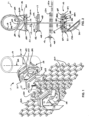
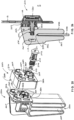
- a first embodiment of a fastener assembly 11 for mounting panels 12 may generally comprise an elongate flexible tie in the form of a strap 14, a saddle 15 and clamping block 16 for engaging the strap 14.
- the fastener assembly 11 provides for the attachment of the panels 12a, 12b to a generally upright post and rail framework, as of a guard rail (e.g. see Figs. 13 and 14 ) or scaffold, for drop protection.
- a guard rail e.g. see Figs. 13 and 14
- scaffold for drop protection.
- Common variations in the construction of such frameworks should be accommodated by the invention in such a way that the panels 12a, 12b are, like the frameworks, generally upright.
- One framework variation, for instance is in the manner that the rails are connected to the posts, where either short rail lengths can span between posts that interrupt a plane of the rail lengths, or else long rails can be fixed alongside the posts. Variations in the horizontal distance between the generally upright plane of the panel and a support surface provided by the posts, or rails, thus needs to be accommodated.
- the saddle 15 serves either alone, or in combination with one spacer 17, or with a plurality of stacked spacers 17 (not shown), to provide a planar outer face selectively positioned relative to the member 13 to abut a panel 12a, 12b opposite the clamping block 16.
- complementary coupling means are provided on the saddle 15 and each spacer 17.
- a female coupling 47 is recessed in the outer face 21 of the saddle 15.
- the spacers 17 each have opposing inner and outer surfaces 45, 46 substantially parallel to one another, and a male coupling 44 projecting from the inner surface of the spacer 17 that is complementary to the female coupling 47 on the saddle 15 and a female coupling 43 recessed in the outer surface 46 that is of like form to the female coupling 47.
- the cooperating female and male couplings 43, 44 and 47 may comprise a snap fit. These couplings 43, 44 and 47 allow multiple spacers to joined together if required, and also connected to the saddle 15, forming a single assembly.
- the spacer 17 further comprises a strap-receiving channel 48 extending between the inner surface 45 and an opposing outer surface 46.
- the strap 14 may have an integral head 19 formed on the proximal end and received in the saddle 15 in a through-extending aperture 20 having a stepped form comprising a complementary mouth part 20a that is proximate an outer face 21.
- the head 19 cannot pass through an adjacent throat part 20b when tension is applied to the strap 14, thus securing the strap 14 to the saddle 15.
- Inclined ratchet serrations 22 may be disposed in a continuous longitudinal array on a side of the strap 14.
- the saddle 15 may be formed in one-piece, as by moulding from polymeric material. It has the outer face 21 for abutting the panel or, as shown, a spacer 17 for abutting the panel. Opposite the outer face 21, an inner face 23 of the saddle 15 abuts the post member 13.
- the inner face 23 may comprise coplanar surfaces 24, disposed generally parallel to the outer face 21 for abutting a framework member with a planar surface, as shown in Fig. 3 . Between the coplanar surfaces 24 a concave surface 25 may be provided with an axis 26 parallel to the outer face 21.
- the concave surface may be cylindrical, or a like axially aligned surface in which every point on the concave surface 25 generally lies on a line parallel to the axis 26.
- the outer face 21 is approximately parallel to the longitudinal axis of the framework member.
- the saddle 15 further includes a strap-receiving channel 27 therethrough, generally between the inner face 23 and the outer face 21.
- the strap-receiving channel 27 may have a slotted form, elongated parallel to the axis 26, since the strap is aligned a major dimension of the cross-section of the strap is aligned parallel to axis 26.
- a saddle tooth 28 may be integral with the saddle 15 and disposed in the strap-receiving channel 27.
- the saddle tooth 28 is connected by a living hinge 29 by which, after passing the strap through the strap-receiving channel 27, the saddle tooth 28 is resiliently urged to engage the serrations 22 and prevent the strap 14 being drawn over the tooth 28 in the opposite direction. Any tension applied to the strap 14 in this opposite direction serves to draw the tooth to more firmly grip the strap.
- the distal end of the strap 14 extends through the aperture 27 and projects from the outer face 21, while the proximal section of the strap 14 forms a loop adjacent the inner face 23 about the framework member 13.
- the clamping block 16 is also preferably formed in one-piece from polymeric material.
- the clamping block 16 may have a centrally located strap-receiving channel 32 extending between an inner side 33 and an opposing outer side 34.
- a tab 35 integral with the clamping block 16 may have an array of clamping block teeth 36 complementary to the serrations 22 and disposed in the strap-receiving channel 32. Passing the strap 14 through the strap-receiving channel 32 engages the securing teeth 36 with the serrations 22.
- the tab 35 provides a cantilever-type resilient mounting for the teeth, and flexure of tab 35 allows enough deflection for the teeth 36 to ride over the serrations 22, when the strap 14 is pulled away from the outer side 34, while preventing reverse movement.
- a recess 37 may be formed in the periphery of the outer side 34 for receiving the strap 14.
- a hinged piece 30 is connected to the clamping block by a hinge 31.
- the hinged piece 30 is shown open in Figs 1 and 2 , and closed in Figs 5 and 6 .
- the hinge 31 may be formed by two opposing nubs 55, 56 aligned coaxially to define a hinge axis, and formed on the tips of respective protruding tongues 57, 58.
- the hinged piece 30 is thus fixed to the clamping block 16 by resilient deflection of the tongues 57, 58 when they are pushed past a shoulder into a slot 59 located near an edge of the outer side 34 of the clamping block 16.
- the panels 12 are of mesh construction, including an array of like openings suitable for receiving the strap 14.
- the mesh may have a honeycomb pattern - of nested hexagonal openings - for structural efficiency.
- the webs 40 are all of like elliptical form, with the long axis of the ellipse aligned transversely, between the outer faces 41, 42 for reduced aerodynamic drag.
- the saddle 15 may be first fixed to the framework, as by forming the loop about the member 13, 113 and pulling the strap 14 through the strap-receiving channel 27 to protrude from the outer face 21, as shown in Fig. 3 .
- a plurality of the saddles 15 may be fixed, as to posts or rails of the framework, and the result is a set of straps 14 protruding generally parallel to one another, away from their respective saddles 15.
- a single installer can then readily place a panel, inserting the straps 14 through openings in the mesh, and thus the panel is conveniently temporarily located and supported on the straps 14.
- At least two of the plurality of saddles 15 and associated protruding straps 14 are horizontally spaced apart and may support the weight of the panel between the two, as near opposite ends of the panel.
- the major dimension of the cross-section of the strap 14 is preferably aligned vertically, for greater bending stiffness.
- Lengthwise ends of adjacent panels 12a, 12b may be overlapped to provide a continuous barrier, as shown in Fig. 1 , avoiding any interruptions at these joints.
- each strap 14 is fed through the strap-receiving channel 32 in a respective clamping block 16.
- the strap 14 is tensioned and, in the case of a permanent installation, the distal end protruding from the outer side 34 may be cut off, before the hinged piece 30 is closed, and latched, as by a snap fit. In a temporary installation, the distal end is not cut off, but is instead bent and threaded through an opening in the mesh panel 12a, 12b, as shown in Fig. 5 .
- the strap 14 is received in the recess 37 before the hinged piece 30 is closed. If installed in this temporary manner, it is possible to remove the fastening assembly 11 if required, without cutting the strap 14, and so permitting re-use. To do so, the hinged piece 30 is opened and a tool such as a screw driver can be inserted to deflect the tab 35 away from the strap 14, allowing the clamping block 16 to be pulled off the strap 14, before releasing the saddle tooth 28 and saddle 15 in a like manner.
- a tool such as a screw driver
- the clamping block 16 may also be used together with the strap 14 to provide a two-component self-mating fastening device for assembling other components of the barrier system. This is achieved by providing two additional apertures extending between the inner and outer sides of the saddle 15, which may be located either side of the strap-receiving channel 32 and comprise: a head-receiving aperture 38 and a strap-receiving channel 39. While this function could be achieved by adding the head-receiving aperture 38 alone, providing an additional strap-receiving channel 39 allows the size of the clamping block 16 to be reduced.
- the head-receiving aperture 38 has a mouth part 38a proximate the outer side 34 for receiving the head 19 and an adjacent throat part 38b adjacent the inner side 33 and through which head 19 cannot pass.
- a tab 135 integral with the clamping block 16 has an array of clamping block teeth 136 complementary to the serrations 22 and disposed in the strap-receiving channel 39. Passing the strap 14 through the strap-receiving channel 39 engages the securing teeth 136 with the serrations 22.
- the tab 135 provides a cantilever-type resilient mounting for the teeth, and flexure of tab 135 allows enough deflection for the teeth 136 to ride over the serrations 22, when the strap 14 is pulled away from the outer side 34.
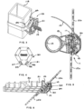
- Fig. 6 shows one application for this fastening device comprising the clamping block 16 together with the strap 14 only, where the framework member has a mounting face aligned obliquely to the pane of the panels.
- this fastening device may be used to secure inclined panels below a staircase of a type having open risers.
- the panels 12a, 12b, 12c, 12d, 12e may be connected to a stair tread 50 formed, for instance, from a grating by passing the loop of the strap 14 through the opening 51.
- Fig. 6 illustrates the permanent installation, where the distal end 52 of the strap 14 protrudes a small distance from the outer side 34, the distal end having been cut short.
- the mesh panels 12 of the barrier system may be formed of moulded polymeric material and come in different shapes, but the main panel 12a is rectangular with an aspect ratio of about 2:1 and is best seen in Figs 7 and 8 .
- the planar honeycomb structure of each panel is surrounded by a perimeter frame 230 that is an integral part of the panel and which is continuous and imperforate to provide a smooth, uninterrupted edge that strengthens the panel and avoids snagging.
- the depth of the perimeter frame 230 i.e. the distance between the panel edge and the closest adjacent mesh opening
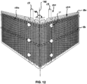
- the mesh panels of the barrier system may further include corner panels 12c that are rectangular and may have an aspect ratio of less than 1:1.
- Notches 75 formed in edge stiffeners 70 along two opposing edges and in the frame 230 are disposed in a regular, rectangular array. The notches 75 are thus aligned top and bottom with the transverse edges of the panel 12c and locally reduce the bending stiffness of the panel so as to define transverse, parallel hinge axes 76 along which the panel 12c may bend.
- the barrier system is mounted to a framework which may comprise upright post members 13 connected to a horizontal hand rail 80, intermediate rail 81 and toe rail 82 and the corner panel 12c accommodates a change of direction of the barrier in a horizontal plane.
- a dihedral angle 78 which in this example is approximately 90°, exists in a horizontal plane between the panels 12a, 12b which are connected at this corner by a corner panel 12c to provide a continuous barrier.
- the two upright halves of the panel 12c separated by the upright hinge axis 76 are parallel to, and in abutment with the panels 12a, 12b.
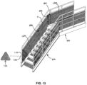
- the barrier system further includes triangular panels 12d used as infill panels where required, such as at the lower end of a stairway 84.
- the barrier system shown includes a rectangular panel 12a (alongside the walkway 85) that is upright, with its longitudinal axis horizontal.
- One upright, transverse edge 86 of panel 12a is disposed at the edge of the stairway 84.
- a triangular part located at the uppermost longitudinal end of the panel 12b is cut out, leaving a cut edge 87 that is aligned generally upright.
- the panels overlap in the lengthwise direction, and the edge 87 of the panel 12b overlaps the transverse edge 86 and the overlapped section is connected by fastener assemblies 11.
- the rectangular panel 12b is mounted with its long axis inclined vertically at the angle of the stairway 84, leaving a triangular gap (not shown) bounded by: the lowermost longitudinal end of the panel 12b, the post 113 and the beam supporting the stairway 84.
- This triangular gap is filled by the triangular panel 12d, located with a first edge adjacent to, and parallel to the post 113, a second edge adjacent to, and parallel to the beam supporting the stairway 84 and a third edge overlapping the end of the panel 12b.
- the combination of rectangular panels 12a, 12b and the triangular panels 12d provides a barrier that extends continuously from the end post 113 up the stairway 84 and along the walkway 85.
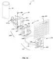
- a second embodiment of the fastener assembly 111 is shown in Figs 14 to 20 and, like the first embodiment, generally comprises an elongate flexible tie in the form of a strap 114, a saddle 115, one or more spacers 117 and clamping block 116 for engaging the strap 114 for mounting panels 12a, 12b to the framework members 13.
- the clamping block sub-assembly 221 of clamping block 116, hinged piece 130 and strap 114 can be used together in the same fastening applications for fixing the strap in a loop around components to be joined in other applications independent of the saddle 115 and spacers 117.
- the saddle 115 includes opposing arms 60a, 60b used to clip the saddle 115 temporarily to the framework member 13.
- the saddle 115 may be formed in one-piece, as by moulding from resilient material.
- the outer face 121 and an opposing inner, concave face 125 are formed on a base part 61 of the saddle 115.
- the two arms 60a, 60b are of generally like form, largely having reflective symmetry about a plane 167 bisecting the saddle 115.
- the arms 60a, 60b project inwardly from opposite edges of the base 61 to bound a space 66 for receiving the member 13.
- Each arm 60a, 60b may have a respective concave inner face 62 for abutting the member 13 and an opposing outer face 63.
- Each concave face 62 may intersect with a tapered face 64 at a neck 65, the tapered faces 64 diverging in a longitudinal direction of each arm 60a, 60b from the intersection toward a respective end of the arm, to assist in entering the member 13 past the neck 65 into space 66.
- the concave faces 62 may have respective axes that extend parallel to axis 26 of concave face 125. These faces 62, 125 may have the same radius of curvature, so they are able to simultaneously abut a member 13 that has a cylindrical outer surface of the same radius.
- the arms 60a, 60b are able to grasp cylindrical outer surface of a range of radii, thereby holding the saddle on the member 13.
- a concavity 67 in the base 61 at an inner end of each arm 60a, 60b causes opposing edges 68 of the concave surface 125 to project.
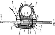
- An inner end of the concavity 67 is arcuate and bounds a hinge portion 69 connecting each arm to the base 61, and permitting the arms 60a, 60b to deflect resiliently from the normal, relaxed state ( Fig. 19 ) to a maximum opening when the diameter of member 13 is in the neck 65 (not shown) to a clamped state ( Fig. 17 ) providing sufficient clamping to support the saddle 115 on the member 13.
- the strap-receiving channel 127 may extend longitudinally through each arm 60a, 60b forming a notch part 127a at the intersection with the base 61 that reduces the stiffness of the hinge portion 69 by forming the hinge portion 69 as two parts 69a, 69b, as best seen in Fig. 18 .
- Each arm 60a, 60b further comprises a pair of substantially parallel ribs 170, 171 elongated in the longitudinal direction of the respective arm and located either side of a channel part 127b disposed at an outer end of the strap-receiving channel 127 in each arm.
- An outwardly extending tab 172 may be formed integrally with one of the ribs 170 with an opening 173 for receiving a tether, if required.
- the female coupling 147 on the saddle 115 comprises a shallow recess in the outer face 121, such that the outer face 121 is continuous around the perimeter of the recess.
- the female coupling 147 may have waisted shape, narrowed in a central part by the opposing notches 127a. Grooves 174 in the female coupling 147 may be configured to receive nubs (not shown) in the male coupling 144 to provide the snap fit connecting the spacer 117.
- the spacer 117 is shown in Figs 14 to 17 and may generally have a rectangular prismatic form with a like waisted shape, narrowed in a central part by the opposing notched strap-receiving channels 148a, 148b that extend between the inner side 145 and the opposing outer side 146 and are respectively located for registration with the strap-receiving channel 127 in each arm 60a, 60b.
- the saddle 115 serves either alone, or in combination with one spacer 117, or with a plurality of stacked spacers 117 (not shown), to provide a planar outer face, selectively positioned relative to the member 13 to abut a panel 12a, 12b opposite the clamping block 116.
- these couplings 143, 144 and 147 allow multiple spacers to be joined together if required, and also connected to the saddle 115, forming a single assembly.
- a flange 205 protruding from a corner of the spacer 117 may include an aperture for tethering the spacer.
- An elongate flexible tie in the form of strap 114 may comprise a strip of stainless steel completely enveloped in a thin, flexible polymeric coating, for a long service life, even an extremely corrosive environment.
- the head 119 may be formed by doubling over the end of the strap upon itself, and forming an approximately right angle bend in the strap adjacent the doubled-over end 180.
- the doubled-over end 180 may be received in a reinforcement 181 that is of material that is harder than the material of the clamping block 116, and which is larger than the doubled-over end 180 to distribute the strap tension load into the clamping block 116 over a greater area.
- the head 119 is received in the clamping block 116 in a through-extending aperture having a stepped form comprising a mouth part proximate the outer face for receiving the head and an adjacent throat part through which head cannot pass.
- the strap 114 and clamping block 116 are connected as an assembly (shown in Fig. 14 ) with the strap projecting from the inner face 133.
- the hinged piece 130 is also connected to the strap 114 and clamping block 116 assembly by a hinge for pivoting between a closed position ( Fig. 16 ) in which the hinged piece 130 has an inner surface 197 that substantially overlies the outwardly directed face 190 of the clamping block 116 and an open position ( Fig. 15 ).
- the hinge may comprise cylindrical external surfaces 183a, 183b formed on the hinged piece 130 and received in respective complementary pivot-receiving recesses 184a, 184b formed in the clamping block 116.
- the clamping block 116 may generally comprise raised, generally straight edges 187, 188, 189 intersecting at corners of the block to define a recess 186 with the outwardly directed face 190. Projecting outwardly from face 190 in a cantilevered manner are tabs 185a, 185b that bound the pivot-receiving recesses 184a, 184b and which are able to resiliently deflect such that the hinged piece 130 is connected to the clamping block 116 by a snap fit.
- a first strap-receiving channel 191 extending through clamping block 116 between opposing inner and outer sides may be disposed between the recesses 184a, 184b to bisect the hinge.
- a second through-extending strap-receiving channel 192 may be disposed next to the opening 191 on an outer side of the hinge recesses 184a, 184b.
- the inner face 133 is planar.
- An aperture 194 may be provided for the attachment of a tether.
- a tab-receiving opening 200a, 200b each extending between the inner side 197 and an outer side 201 and receiving a respective one of the tabs 185a, 185b in the closed position for a low profile closed position.
- a slot 195 in the hinged piece 130 has a form complementary to the cross-section of the strap 114 providing means for gripping the strap 114.
- the slot 195 is disposed between the cylindrical external surfaces 183a, 183b and extends transverse to the hinge axis 196 so that, with the tie-receiving channel in the open position, the slot 195 is adjacent to and aligned with the first strap-receiving channel 191 in the block 116.
- the slot 195 extends out to an inner side 197 of the hinged piece 130, in alignment with a channel 198 in the inner side 197.
- latching lugs 199 are formed for engaging a surface of the clamping block 116 for latching the hinged piece 130 closed.
- a shallow channel 206 may be provided for receiving the strap 114.
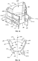
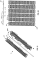
- FIGS 21 to 23 illustrate a corner panel assembly 12e of a second embodiment of the invention in which an assembly of a plurality of rectangular panels 231, 232 include continuous hinges along their longitudinal edges, allowing the corner panel assembly 12e to fold along parallel hinge axes to generally follow corners of multiple different radii.
- the panels may include edge panels 231 at opposite edges of the assembly 12d with a continuous hinge along only one edge, and panels 232 with a continuous hinges along both long edges.
- Hinge pins 233 extend for the length of the panels 231, 232 and connect interleaved pin-receiving projections 231a and 232a of the panels 231, 232 to form the hinges.
- the pins 233 may be covered by a tubular sheath 232 (shown partially removed from the pin 233 in Fig. 21 ) and formed from a compliant material, such as a silicon rubber, and which is fitted in openings in the panels to provide friction, or a shock-absorbing function.
- a compliant material such as a silicon rubber
- Fig. 24 shows a corner panel 12f of a third embodiment of the invention which provides for both a single smooth curvature, and a curvature of larger radius, compared to the first and second embodiments, in which multiple step-wise curves of smaller radius are used. This is achieved simply by providing a flat panel that is sufficiently flexible to be readily manually bent about an upright axis during installation so as to span a corner.
- the panel 12f is of like form to the panel 12a but the frame 230 is flat i.e the panel 12f lacks the stiffening channel 74 along one edge of the panel 12a.
- the barrier system may further comprise one or more brackets 252, 290, 291 that, in use, are mounted near the lower edge of the mesh panels 12, using the clamping block sub-assembly 221 comprising the clamping block 116, hinged piece 130 and strap 114 (or else, and not shown, the assembly comprising the clamping block 16, hinged piece 30 and strap 14) in order to support the lower edge in abutment with an adjacent structural member, such as a toe rail 255.
- brackets 252, 290, 291 that, in use, are mounted near the lower edge of the mesh panels 12, using the clamping block sub-assembly 221 comprising the clamping block 116, hinged piece 130 and strap 114 (or else, and not shown, the assembly comprising the clamping block 16, hinged piece 30 and strap 14) in order to support the lower edge in abutment with an adjacent structural member, such as a toe rail 255.
- the bracket 252 has a face 253 for engaging a complementary surface of the mesh panel 12 and a channel 254 adapted for receiving a toe rail 255 with the form of a flat bar, or the like.
- the closed end of the channel defines a support surface 394 substantially perpendicular to the face 253, through which the weight supported by the bracket is transferred to the framework that it rests on.
- the face 253 may be planar, with the channel 254 parallel to the face 253 and to the plane of the mesh panel 12.
- the bracket 252 may be aligned upright with a tapered mouth 256 of the channel 254 lowermost, and below the face 253, allowing the bracket 252 to be readily lowered over the toe rail 255.
- the channel 254 may be formed between two tongue portions 257, 258 integral with the bracket 252. Projecting from the face 253 is an array of tabs 259, 260 sized to be received within the hexagonal openings of the mesh panel 12. Recesses or openings 280, 281 in the bracket 252 for receiving the strap 114 may be disposed in opposing sides of the face 253.
- the bracket 252 may be formed in one-piece, as by moulding from polymeric material.
- the tabs 260 may each be adapted to span a side of one hexagonal opening and they are spaced apart in the circumferential direction, and define divergent external surfaces 267 that diverge to a radially outermost lip 261. Internally of its divergent external surfaces 267 each tab 260 may have a cylindrical face 268.
- the resilience of the tabs 260 thus provides a snap-fit fastening between the bracket 252 and mesh panel 12, whereby after being bent inwardly to allow them to pass through the hexagonal opening, the lips 261 are urged outward to retain the tabs 260 in the hexagonal opening.
- the bracket 252 can be used alone, or as in a bracket assembly 250 that further comprises one or more spacer blocks 262 and a fastener 263.
- This bracket assembly 250 may be used in barrier installations where the horizontal distance between the plane of the mesh panel 12 and the toe rail 255 is greater than that which can be spanned by a single bracket 252 alone.
- the spacer block 262 has opposing outer and inner sides 264, 265 replicating the cooperating attachment features of the bracket 252 and mesh panel 12 respectively.
- the inner side 265 is complementary to the face 253 with which it abuts, while it further comprises internal hexagonally arrayed surfaces 266 (of a form corresponding to those on the mesh panel 12) for engaging with the tabs 260 in a snap-fit.
- An aperture 269 extends centrally between the array of tabs 260 between the outer and inner sides 264, 265.
- the outer side 264 comprises tabs 359, 360 of like form to the tabs 259, 260 that project from a face 270. Openings 282, 283 in the spacer block 262 for receiving the strap 114 may be disposed in opposing sides of the face 270 for alignment with the openings 280, 281.
- the fastener 263 may have a tool formation 271 such as a slot for a screwdriver.
- Coaxial cylindrical portions 272, 273 are connected to an external screw portion 274 that terminates in a resilient bifurcated retaining head 275.
- the bracket 252 has an internal screw thread 277 and an internal shoulder 276 that engages the head 275 to retain the fastener 263.
- the fastener 263 is inserted through the aperture 269 into the corresponding opening in the bracket 252, where it is retained by the cooperating retaining head 275 and shoulder 276, optionally with partial engagement between the screw threads 274, 277.
- the spacer block 262 and bracket 252 are connected by the snap-fit, and the spacer block 262 may then be connected to the mesh panel 12 by inserting the tabs 259, 260 into the hexagonal openings. Subsequent turning of the fastener 263 displaces the cylindrical portions 272, 273 axially to the positions shown, where they are in registration with the respective cylindrical faces 268 on the bracket 252 and spacer 262, thereby blocking inward deflection of the tabs 260, 260 sufficient to permit disengagement of the connected parts.
- the spacer block 262 is paired with the fastener 263 in as much as to provide different spacing between the outer and inner sides 264, 265 requires a fastener of a different axial length.
- the barrier system may comprise multiple pairs of spacer blocks 262 and respective fasteners 263 to suit different offsets or, if the spacer blocks are stacked a fastener may be provided according to the stacked dimension.
- the bracket assembly 250 may be fixed to the mesh panel 12 in the workshop, or prior to installation, with the appropriately sized spacer block 262 and fastener 263, thereby reducing the assembly required to be completed on site. When the mesh panel 12 and attached bracket assembly 250 are positioned ready for final installation, this is completed using the clamping block sub-assembly 221.
- the strap 114 With the head 19 of the strap 114 received in the recess in the clamping block 116, the strap 114 is passed in one direction through the mesh panel 12, through the aligned openings 280, 282 on one side, and back upon itself through opening 261 around the bracket 253, before continuing in the opposite direction through the aligned openings 281, 283 on the other side and through the mesh panel 12, and through the tie-receiving aperture 39, before it is tightened and closed to secure the strap 114 in a loop in the manner described below.
- the brackets 290, 291 are of like form except for a projection 292 formed on the bracket 290 and absent from bracket 291.
- Each has a planar face 292 on a front side for engaging a complementary surface of the mesh panel and a substantially perpendicular support surface 294 through which the weight supported by the bracket is transferred a floor that it rests upon.
- Opposing the face 292 are faces 295, 296 of the brackets 290, 291 respectively, with the face 295 being formed on the outer end of the projection 292.
- a ledge 298 may project forward of the face 293. Openings 299, 300 extend from the face 293 between the inner and outer sides of the brackets 290, 291.
- Fig. 29 shows the bracket 291 mounted in this manner and secured to the panel 12 using the clamping block sub-assembly 221 of the clamping block 116, hinged piece 130 and strap 114, where the clamping block 116 and hinged piece 130 may abut a rear side 301 of the brackets 290, 291, such that only a loop portion (not shown) of the strap 114 protrudes from the outer side of the panel 12.
- the barrier system components may be supplied to site accurately configured for the intended application, with the correct number of panels 12a, 12b, 12c, 12d, 12e, 12f of each required type and the corresponding requisite number of the fastening components described above, including: fastener assemblies 111, clamping block sub-assemblies 221 (clamping block 116, hinged piece 130, and strap 114 or clamping block 16, hinged piece 30, and strap 14), as well as of brackets 252, 290, 291 and bracket assemblies 250.
- the fastener assemblies 111 comprise a saddle sub-assembly 220 (comprising a saddle 115 and zero or more spacers 117 attached thereto as described above).
- the thickness of spacers 117 (if any) on each saddle sub-assembly 220, the thickness of spacer blocks 262 and the length of the strap 114 on the clamping block sub-assembly 221 may be application-specific.
- a panel 12a is then placed to generally overlie the faces 121, 146 and each clamping block sub-assembly 221 is fixed to each saddle sub-assembly 220, passing the strap 114 through the panel (note that in Figs 15 and 16 the panel is omitted for clarity) then about the member 13 so that it is received in the strap-receiving channels 148a, 148b, 127a, 127b before the distal end is inserted through the first strap-receiving channel 191 and through the slot 195 (see Fig. 15 ).
- the loop thus formed around the member 13 is reduced in size to clamp the saddle 115 and clamping block 116 together. This is done firstly by manually applying tension to the strap 114, then using the hinged piece 130.
- Tension is best applied by turning the tensioned strap 114 around the free end 202 of the hinged piece 13, pulling it straight between the slot 195 and the free end 202, before turning the strap 114 about the free end 202 and back along the channel 205 toward the hinge.
- Friction in the slot 195 and caused by turning the strap 114 around the free end 202 also tends to prevent sliding of the strap relative to the hinged piece 130 so that manually turning the hinged piece 130 to its closed position draws the strap 114 through the first strap-receiving channel 191.
- the slot 195 provides gripping means adjacent the tie-receiving channel for gripping the strap 114 beyond the friction, due to the local changes in direction of the strap caused by turning the slot 195. With the hinged piece closed, the distal end of the strap 114 may then be passed through the second strap-receiving channel 192 and through the panel, to project from the outer side of the panel and keep the inside clear.
- the hinged piece 130 In the closed position ( Figs. 16 and 17 ), the hinged piece 130 is received within the recess 197 and it lies at or within the boundary of any profile view of the clamping block 116 in a plane perpendicular to the inner side 133, thereby providing the fastener with a low profile that mitigates obstruction.
- the clamping block 116 tapers in any profile to narrow toward its outer edges for the avoidance of snagging.
- brackets 252, 290, 291 may still be connected by snap-fit to the panels 12 before being secured with respective clamping block sub-assemblies 221.
- the panels 12a are ordinarily arranged such that their longitudinal axes, and lengthwise channel 74 adjacent the edge, are generally horizontal, the panels 12 can be readily cut during installation and panel pieces can be fixed with a length of the channel 74 upright, depending upon the framework to which the barrier is to be fixed.
- Fig. 30 shows a situation where cutting and turning the panel pieces in this manner is advantageous.
- the framework comprises short rail lengths 90 that span between posts 91, the rail lengths 90 together approximately defining an upright plane and a spacing suitable for supporting planar panels.
- a rectangular panel 12 is cut transversely into two panel pieces 112a, 112b that are installed against the rail lengths 90 and inside the outer edges of the posts 91, with their respective edge channels 74 upright, the pieces overlapping one another span-wise.
Landscapes
- Engineering & Computer Science (AREA)
- Architecture (AREA)
- Civil Engineering (AREA)
- Structural Engineering (AREA)
- General Engineering & Computer Science (AREA)
- Mechanical Engineering (AREA)
- Life Sciences & Earth Sciences (AREA)
- Chemical & Material Sciences (AREA)
- Composite Materials (AREA)
- Wood Science & Technology (AREA)
- Clamps And Clips (AREA)
- Fencing (AREA)
- Orthopedics, Nursing, And Contraception (AREA)
- Bridges Or Land Bridges (AREA)
Claims (20)
- Ensemble de fixation (11, 111) pour monter un panneau (12, 12a, 12b) sur un armature (13), l'ensemble de fixation (11, 111) comprenant :une attache (14, 114) flexible allongée ayant une extrémité proximale et une extrémité distale opposée ; etun bloc de serrage (16, 116) comportant un canal de réception d'attache (32) s'étendant entre un côté intérieur et un côté extérieur opposé du bloc de serrage (16, 116), dans lequel l'extrémité proximale peut être fixée au bloc de serrage (16, 116), et un moyen de préhension (59, 195) adjacent au canal de réception d'attache (32) pour saisir l'attache (14, 114) ;dans lequel, en cours d'utilisation, le côté intérieur du bloc de serrage (16, 116) vient en butée contre le panneau (12, 12a, 12b) et le moyen de préhension (59, 195) saisit le lien de manière à ce que la tension de l'attache (14, 114) presse le côté intérieur du bloc de serrage (16, 116) contre le panneau (12, 12a, 12b) ;caractérisé en ce que l'ensemble de fixation (11, 111) comprend en outre une pièce articulée (30, 130) reliée par une charnière (31) au bloc de serrage (16, 116) pour pivoter entre une position fermée dans laquelle la pièce articulée (30, 130) a une surface intérieure qui recouvre sensiblement le côté extérieur du bloc de serrage (16, 116) et une position ouverte, dans laquelle une fente (59, 195) dans la pièce articulée (30, 130) a une forme complémentaire à la section transversale de l'attache (14, 114) qui fournit le moyen de préhension adjacent au canal de réception d'attache (32) pour saisir l'attache (14, 114) et, dans la position ouverte, la fente (59, 195) est adjacente et alignée avec le canal de réception d'attache (32) dans le bloc de serrage (16, 116).
- Ensemble de fixation (11, 111) selon la revendication 1, comprenant en outre une selle (15, 115) ayant un canal de réception d'attache (27), une face intérieure concave pour venir en butée contre un élément de l'armature (13) et une face extérieure opposée dans lequel, en cours d'utilisation, la face extérieure de la selle (15, 115) et le côté intérieur du bloc de serrage (16, 116) viennent en butée contre les surfaces opposées du panneau (12, 12a, 12b) et la tension de l'attache (14, 114) serre le panneau (12, 12a, 12b) entre la selle (15, 115) et le bloc de serrage (16, 116).
- Ensemble de fixation (11, 111) selon la revendication 2, dans lequel un raccord femelle (47, 147) est ménagé dans la face extérieure de la selle (15, 115) et l'ensemble de fixation (11, 111) comprend en outre au moins une entretoise (17, 117) ayant des surfaces intérieures et extérieures opposées sensiblement parallèles l'une à l'autre, chaque entretoise (17, 117) ayant un raccord mâle (44, 144) faisant saillie de la surface intérieure de l'entretoise (17, 117) qui est complémentaire du raccord femelle (47, 147) sur la selle (15, 115) et un raccord femelle (43, 143) ménagé dans la surface extérieure de l'entretoise (17, 117) qui est de même forme que le raccord femelle (47, 147) de la selle (15, 115).
- Ensemble de fixation (11, 111) selon la revendication 3, dans lequel l'entretoise (17, 117) comprend en outre un canal de réception d'attache (48) s'étendant entre un côté intérieur et un côté extérieur opposé de l'entretoise (17, 117) pour recevoir l'attache (14, 114).
- Ensemble de fixation (11, 111) selon l'une quelconque des revendications 1 à 4, dans lequel l'attache (14, 114) comprend une tête (19, 119) formée sur l'extrémité proximale et reçue dans une ouverture (20) traversante dans le bloc de serrage (16, 116), l'ouverture (20) ayant une forme étagée comprenant une partie d'embouchure (20a) proche de la face extérieure pour recevoir la tête (19, 119) et une partie de gorge (20b) adjacente à travers laquelle la tête (19, 119) ne peut pas passer et, optionnellement, dans laquelle l'attache (14, 114) comprend une courroie.
- Ensemble de fixation (11, 111) selon l'une quelconque des revendications 1 à 5, dans lequel la selle (15, 115) comprend un matériau résilient, et des bras (60a, 60b) opposés faisant partie intégrante de la selle (15, 115) qui font saillie vers l'intérieur à partir du côté intérieur pour fixer la selle (15, 115) à l'armature (13) et, optionnellement,
dans lequel la selle (15, 115) comprend une partie de base (61) sur laquelle la face intérieure concave et la face extérieure sont formées et à partir des bords opposés desquelles les bras (60a, 60b) s'étendent et dans lequel une concavité (67) dans la partie de base (61) à une extrémité intérieure de chaque bras (60a, 60b) est arquée et délimite une partie de charnière (69) reliant chaque bras (60a, 60b) à la partie de base (61). - Ensemble de fixation (11, 111) selon la revendication 6, dans lequel chaque bras (60a, 60b) comprend une face concave intérieure qui croise une face effilée (64) au niveau d'un col (65), les faces effilées (64) s'écartant d'un sens longitudinal de chaque bras (60a, 60b) à partir du col (65) vers une extrémité respective du bras (60a, 60b) et chaque bras (60a, 60b) comprend en outre une paire de nervures sensiblement parallèles (170, 171) allongées dans le sens longitudinal du bras (60a, 60b), et disposées de part et d'autre d'un canal (127b) destiné à recevoir l'attache (14, 114).
- Ensemble de fixation (11, 111) selon l'une quelconque des revendications 1 à 7, dans lequel la charnière (31) comprend une surface externe cylindrique (183a, 183b) reçue dans un évidement complémentaire de réception de pivot (184a, 184b) dans l'un de la pièce articulée (30, 130) et du bloc de serrage (16, 116), dans lequel ledit - élément parmi la pièce articulée (30, 130) et le bloc de serrage (16, 116) est formé d'un matériau résilient, de sorte que la pièce articulée (30, 130) est reliée au bloc de serrage (16, 116) par un système d'encliquetage.
- Ensemble de fixation (11, 111) selon l'une quelconque des revendications 1 à 8, dans lequel le bloc de serrage (16, 116) comprend en outre un deuxième canal de réception d'attache (192), dans lequel le deuxième canal de réception d'attache (192) et le premier canal de réception d'attache (32) sont situés à proximité des côtés opposés de la charnière (31), de sorte que l'extrémité distale peut être passée vers l'extérieur à travers le premier canal de réception d'attache (32), autour de la pièce articulée (30, 130), et à l'intérieur à travers le deuxième canal de réception d'attache (192) et, optionnellement,
dans lequel la tête (19, 119) est formée en doublant la sangle sur elle-même, la tête (19, 119) étant reçue dans un évidement étagé d'un renfort (181), le renfort (181) étant reçu dans l'ouverture (20) étagée du bloc de serrage (16, 116). - Ensemble de fixation (11, 111) selon l'une quelconque des revendications 1 à 9 dans lequel, sur une extrémité de la pièce articulée (30, 130) opposée à la charnière (31), des pattes de verrouillage (199) sont formées pour s'engager dans un évidement complémentaire sur le bloc de serrage (16, 116) pour verrouiller la pièce articulée (30, 130) en position fermée et, optionnellement,dans lequel le bloc de serrage (16, 116) comprend un évidement et, en position fermée, la pièce articulée (30, 130) est reçue dans le évidement et/ou, optionnellement,dans lequel, lorsque la pièce articulée (30, 130) est fixée au bloc de serrage (16, 116) en position fermée, la pièce articulée (30, 130) se situe en une vue de profil quelconque du bloc de serrage (16, 116) dans un plan perpendiculaire au côté intérieur (33) ou au niveau de celui-ci et, optionnellement, dans ce profil quelconque, le bloc de serrage (16, 116) s'effile pour se rétrécir vers ses bords extérieurs.
- Ensemble de fixation (11, 111) selon la revendication 8, dans lequel la surface cylindrique (183a, 183b) se situe sur la pièce articulée (30, 130) et l'évidement de réception du pivot se situe sur le bloc de serrage (16, 116), l'évidement de réception du pivot est formée par une languette (185a, 185b) qui fait saillie généralement vers l'extérieur à partir du côté extérieur (34) du bloc de serrage (16, 116), et une ouverture de réception de la languette (200a, 200b) s'étendant à travers la pièce articulée (30, 130) reçoit la languette dans la position fermée.
- Ensemble de fixation (11, 111) selon la revendication 8, dans lequel l'attache (14, 114) est alignée de telle sorte qu'une dimension majeure de la section transversale de l'attache (14, 114) est alignée parallèlement à un axe (76) de la charnière (31) et, optionnellement,
dans lequel un canal est formé sur la face extérieure de la pièce articulée (30, 130) pour recevoir l'attache (14, 114). - Ensemble de fixation (11, 111) selon l'une quelconque des revendications 2 à 12, dans lequel l'attache (14, 114) comprend des dentelures (22) à cliquet disposées dans un réseau longitudinal sur un côté de la sangle ;la selle (15, 115) est fixée à l'extrémité proximale, la selle (15, 115) comprend en outre au moins une dent de selle (28) intégrée à la selle (15, 115) et disposée dans le canal de réception d'attache (27) de sorte que le passage de l'attache (14, 114) à travers le canal de réception d'attache (27) engage la dent de selle (28) avec les dentelures (22) sur l'attache (14, 114) forme une boucle adjacente à la face intérieure pour passer autour d'un élément de l'armature (13) et l'extrémité distale de l'attache (14, 114) fait saillie de la face extérieure, etle bloc de serrage (16, 116) comporte une dent de bloc de serrage intégrée au bloc de serrage (16, 116) et disposée dans l'ouverture du canal de réception d'attache, de sorte que le passage de l'attache (14, 114) à travers l'ouverture du canal de réception d'attache engage la dent de bloc de serrage avec les dentelures (22) sur l'attache (14, 114).
- Système de barrière comprenant : un ensemble de fixation (11, 111) tel que revendiqué selon l'une quelconque des revendications 1 à 13 et un panneau à mailles (12, 12a, 12b) réalisé en matériau polymère et ayant des mailles en forme de nid d'abeilles.
- Système de barrière selon la revendication 14, dans lequel les bandes (40) de mailles en forme de nid d'abeilles ont une section transversale généralement elliptique, avec un axe long de la section transversale elliptique aligné transversalement au panneau à mailles (12, 12a, 12b).
- Système de barrière selon la revendication 15, dans lequel le panneau à mailles (12, 12a, 12b) comprend en outre un cadre périmétrique (230) qui entoure la maille en forme de nid d'abeilles et en fait partie intégrante, le cadre périmétrique (230) étant continu et non perforé et, optionnellement, dans lequel le panneau à mailles (12, 12a, 12b) a une forme rectangulaire avec un raidisseur (70) intégral s'étendant de manière continue le long d'au moins un des bords longs du panneau (12, 12a, 12b).
- Système de barrière selon la revendication 16, dans lequel le raidisseur (70) est de forme constante sur toute sa longueur et définit un canal et, optionnellement, dans lequel le raidisseur (70) intégral comprend des raidisseurs (70) intégraux s'étendant continuellement le long de deux bords opposés du panneau (12, 12a, 12b), les encoches (75) dans les deux bords opposés sont disposées en un réseau rectangulaire régulier, les encoches (75) étant alignées de manière à définir des axes (76) de charnière parallèles entre les encoches (75) sur les bords opposés, de sorte que le panneau (12, 12a, 12b) peut se plier le long des axes (76) de charnière parallèles.
- Système de barrière selon la revendication 15 ou la revendication 16, comprenant un ensemble de panneaux d'angle (12e) composé d'une pluralité de premiers panneaux rectangulaires (231, 232) comportant chacun des charnières continues le long des deux bords longs, chacun des premiers panneaux rectangulaires (231, 232) est relié à un panneau rectangulaire adjacent du premier panneau rectangulaire (231, 232) par l'une des charnières continues, et, optionnellement
comprenant en outre deux deuxièmes panneaux rectangulaires (231, 232), chacun avec une charnière continue le long d'un bord, dans lequel les panneaux opposés les plus à l'extérieur des premiers panneaux rectangulaires (231, 232) sont chacun reliés à l'un des deux deuxièmes panneaux rectangulaires (231, 232) par une charnière continue respective, et, optionnellement, dans lequel un axe de charnière (233) relie chaque panneau rectangulaire (231, 232) adjacent, et chaque axe de charnière (233) est revêtu d'un matériau résilient. - Système de barrière selon l'une quelconque des revendications 15 à 18, comprenant en outre un support (252, 290, 291) pour soutenir un bord inférieur du panneau en butée avec un élément structurel adjacent (255), le support (252, 290, 291) ayant une face (253) pour s'engager dans une surface complémentaire du panneau (12, 12a, 12b), des évidements dans le support (252, 290, 291) pour recevoir l'attache (14, 114) disposés sur les côtés opposés de la face (253), et une surface de support (394) sensiblement perpendiculaire à la face (253), à travers laquelle le poids supporté par le support (252, 290, 291) est transféré.
- Système de barrière selon la revendication 19, dans lequel le support (252, 290, 291) comprend des languettes (259, 260) flexibles en saillie fournissant un engagement par encliquetage avec des ouvertures du panneau à mailles (12, 12a, 12b) et un bloc d'espacement (262) avec des côtés extérieurs et intérieurs opposés (264, 265) reproduisant les caractéristiques de fixation coopérantes du support (252, 290, 291) et du panneau à mailles (12, 12a, 12b) respectivement pour permettre un engagement par encliquetage entre le support (252, 290, 291) et le côté intérieur du bloc d'espacement (262) et entre le côté extérieur du bloc d'espacement (262) et les ouvertures dans le panneau à mailles (12, 12a, 12b), et une fixation à vis pour bloquer la flexion vers l'intérieur des languettes (259, 260) suffisante pour permettre le désengagement du support (252, 290, 291), du bloc d'espacement (262) et du panneau à mailles (12, 12a, 12b) connectés.
Applications Claiming Priority (2)
| Application Number | Priority Date | Filing Date | Title |
|---|---|---|---|
| AU2016904803A AU2016904803A0 (en) | 2016-11-23 | Fastener Assembly, Mesh Panel and Barrier System | |
| PCT/CN2017/112643 WO2018095371A1 (fr) | 2016-11-23 | 2017-11-23 | Ensemble élément de fixation, panneau en maille et système de barrière |
Publications (3)
| Publication Number | Publication Date |
|---|---|
| EP3545201A1 EP3545201A1 (fr) | 2019-10-02 |
| EP3545201A4 EP3545201A4 (fr) | 2020-07-22 |
| EP3545201B1 true EP3545201B1 (fr) | 2023-06-14 |
Family
ID=62171666
Family Applications (1)
| Application Number | Title | Priority Date | Filing Date |
|---|---|---|---|
| EP17874073.4A Active EP3545201B1 (fr) | 2016-11-23 | 2017-11-23 | Ensemble de fixation et système de barrière |
Country Status (11)
| Country | Link |
|---|---|
| US (1) | US12018491B2 (fr) |
| EP (1) | EP3545201B1 (fr) |
| JP (1) | JP7256129B2 (fr) |
| KR (1) | KR102622855B1 (fr) |
| CN (2) | CN108086790B (fr) |
| AU (1) | AU2017366469B2 (fr) |
| CA (1) | CA3044591A1 (fr) |
| MX (1) | MX2019005876A (fr) |
| MY (1) | MY202286A (fr) |
| SG (1) | SG10202105471SA (fr) |
| WO (1) | WO2018095371A1 (fr) |
Families Citing this family (25)
| Publication number | Priority date | Publication date | Assignee | Title |
|---|---|---|---|---|
| US9611652B2 (en) | 2011-02-25 | 2017-04-04 | Dustin M. M. Haddock | Mounting device for building surfaces having elongated mounting slot |
| CN108086790B (zh) * | 2016-11-23 | 2020-05-12 | Mrm香港有限公司 | 紧固件组件、网格面板和屏障系统 |
| AU2018348090B2 (en) | 2017-10-09 | 2021-11-18 | Rmh Tech Llc | Rail assembly with invertible side-mount adapter for direct and indirect mounting applications |
| EP3769017A4 (fr) | 2018-03-21 | 2021-12-08 | RMH Tech LLC | Ensemble de montage de module photovoltaïque, doté d'agencement d'élément de serrage/douille-entretoise |
| WO2020124011A1 (fr) | 2018-12-14 | 2020-06-18 | Rmh Tech Llc | Dispositif de montage pour des panneaux de bande de clous |
| GB201820716D0 (en) * | 2018-12-19 | 2019-01-30 | J Mac Safety Systems Ltd | A brick guard |
| FR3092380A1 (fr) * | 2019-02-05 | 2020-08-07 | karim meriah | Dispositif de fixation de sac à main ou tout autre sac à une table de type de restauration |
| WO2021026591A1 (fr) * | 2019-08-09 | 2021-02-18 | Dragox Pty Ltd | Barrière et panneau associé |
| CN110639159A (zh) * | 2019-10-09 | 2020-01-03 | 江苏新金菱体育产业集团有限公司 | 一种蹦床防护网的制造方法 |
| GB2589923B (en) * | 2019-12-13 | 2021-12-08 | Three Smith Group Ltd | Strapping apparatus |
| AU2021239839B2 (en) | 2020-03-16 | 2024-12-19 | Rmh Tech Llc | Mounting device for a metal roof |
| SE545538C2 (en) | 2020-06-22 | 2023-10-17 | Elfa Int Ab | Mesh container and method for producing a mesh container |
| BR112023000401A2 (pt) | 2020-07-09 | 2023-01-31 | Rmh Tech Llc | Sistema, dispositivo e método de montagem |
| US11885143B2 (en) * | 2020-07-31 | 2024-01-30 | Harry A. Thompson | Oval cover member for pre-cast concrete lift hook |
| CN112283218A (zh) * | 2020-09-18 | 2021-01-29 | 上海蓝魂环保科技有限公司 | 一种天然气蜂窝状钢板及连接件装置 |
| BE1028616B1 (nl) * | 2020-09-18 | 2022-04-20 | Hego | Valbescherming |
| WO2023039155A1 (fr) | 2021-09-09 | 2023-03-16 | Rmh Tech Llc | Ensemble rail actionné par un couple |
| SE2151577A1 (en) * | 2021-12-21 | 2023-06-22 | Elfa Int Ab | Container and method for producing a container |
| CN114457996A (zh) * | 2022-03-03 | 2022-05-10 | 安徽安久模架科技有限公司 | 一种能够避免剧烈晃动的金属爬架 |
| KR102455364B1 (ko) * | 2022-06-14 | 2022-10-18 | 주식회사 골든포우 | 밴드를 이용한 패널형 도류벽 설치수단 |
| CN115182536B (zh) * | 2022-07-25 | 2023-09-01 | 佛山维尚家具制造有限公司 | 一种挂板式快速装修墙体结构及安装方法 |
| USD1113406S1 (en) | 2023-04-14 | 2026-02-17 | Rmh Tech Llc | Mounting device |
| CN121358993A (zh) | 2023-04-14 | 2026-01-16 | Rmh技术有限责任公司 | 用于金属面板的安装装置 |
| USD1109686S1 (en) | 2023-08-10 | 2026-01-20 | Rmh Tech Llc | Mount for a component of a photovoltaic assembly |
| WO2025166362A1 (fr) * | 2024-02-02 | 2025-08-07 | Rowan University | Éléments et structures de construction cellulaire à construction additive |
Family Cites Families (36)
| Publication number | Priority date | Publication date | Assignee | Title |
|---|---|---|---|---|
| JPS6326561Y2 (fr) | 1985-11-11 | 1988-07-19 | ||
| DK600786D0 (da) * | 1986-12-12 | 1986-12-12 | Bjoern Erik Haabegaard Larsen | Fastgaerelsesorgan til fastholdelse af afdaekningsmateriale, fx i formaf plastfolie eller tekstilmateriale |
| US4899963A (en) * | 1989-02-06 | 1990-02-13 | Murphy Patrick J | Support saddle for elongate articles and interpositioning device for dissimilar surfaces |
| FR2653479B1 (fr) * | 1989-10-23 | 1992-02-14 | Plagnard Claude | Barriere metallique ergonomique. |
| DK164963C (da) | 1990-03-27 | 1993-02-15 | Polysheet As | Fastgoerelsesindretning til fastgoerelse af en beskyttelses- eller afskaermningsbeklaedning til et stillads eller lignende understoetningskonstruktion samt vaerktoej til brug ved montering af fastgoerelsesindretningen |
| JP3014220B2 (ja) | 1992-07-27 | 2000-02-28 | 久生 井出 | 防護用ネット,シートの連結具 |
| IT231299Y1 (it) * | 1993-01-13 | 1999-08-02 | Fapa Spa | Portatutto, portasci o simile, per autoveicoli muniti di portabagagli del dipo cosiddetto americano. |
| DE4304239C2 (de) * | 1993-02-12 | 1999-01-14 | Rixen & Kaul Gmbh | Befestigungsvorrichtung für Zubehör an Rohren oder Stangen |
| US5785616A (en) * | 1995-05-10 | 1998-07-28 | Dodge; Richard C. | Barrier system for a basketball goal |
| US5653409A (en) | 1995-07-25 | 1997-08-05 | Panduit Corp. | Standoff |
| US5702081A (en) * | 1995-12-13 | 1997-12-30 | National Banner Company, Inc. | Bracket apparatus |
| JP2000179158A (ja) | 1998-12-18 | 2000-06-27 | Electric Power Dev Co Ltd | 防護パネル及び飛散防止工法 |
| JP2002068278A (ja) | 2000-08-28 | 2002-03-08 | Hideyuki Yamazaki | バンド梱包具 |
| DE60008899D1 (de) | 2000-12-19 | 2004-04-15 | Moreda Riviere Trefilerias S A | System zum Verbinden von Zäunen oder Panelen an Tragestrukturen |
| DE10153810C1 (de) * | 2001-11-05 | 2003-03-20 | Elkosta Security Systems Gmbh | Befestigungseinrichtung für die Befestigung von gitterartigen Zaunfeldern an einem Zaunpfosten |
| CN200964716Y (zh) * | 2006-09-04 | 2007-10-24 | 北京精诚博桑科技有限公司 | 一种改进的刚性挡风墙 |
| CN1952327A (zh) * | 2006-11-10 | 2007-04-25 | 徐林波 | 用张力拉紧的护栏及围墙 |
| JP2009012799A (ja) | 2007-07-03 | 2009-01-22 | Yasunari Masumoto | 結束バンド |
| NZ563350A (en) | 2007-11-12 | 2010-05-28 | Kiwijoe New Zealand Ltd | Improvements in and relating to attachments, brackets and support assemblies |
| KR20090084481A (ko) * | 2008-02-01 | 2009-08-05 | 김동주 | 파이프 고정클립 및 그 체결기구 |
| CN201193392Y (zh) * | 2008-03-19 | 2009-02-11 | 王东明 | 防雨水减风阻风帽 |
| CN101906881B (zh) * | 2009-05-13 | 2014-08-27 | Mrm香港有限公司 | 防坠落安全网 |
| WO2012023035A2 (fr) * | 2010-08-20 | 2012-02-23 | Shield Projects Limited | Panneau de clôture |
| JP5582974B2 (ja) | 2010-11-10 | 2014-09-03 | 三政物産株式会社 | 落下防止用パネル及びその組立方法、並びに、網状部材組立体 |
| AU2011100489B4 (en) * | 2010-12-15 | 2011-08-11 | Pro3 Safety Pty Ltd | System and components for safely enclosing handrails, stairways, walkways and platforms |
| US8636266B2 (en) * | 2011-08-03 | 2014-01-28 | Bart's Ltd. | Safety barricading system |
| JP5913893B2 (ja) | 2011-10-11 | 2016-04-27 | 矢崎総業株式会社 | ワイヤーハーネスの固定構造 |
| WO2014063202A1 (fr) | 2012-10-25 | 2014-05-01 | Bart's Limited | Agencement de montage réglable |
| CN202954369U (zh) * | 2012-11-23 | 2013-05-29 | 李广文 | 一种三维蜂巢结构绿化网格 |
| CN203050143U (zh) * | 2013-01-15 | 2013-07-10 | 辛华 | 建筑安全网的带扣式绑扎件 |
| CN203237579U (zh) | 2013-03-05 | 2013-10-16 | 上海易扣精密件制造有限公司 | 圆孔固定型可释放捆扎带 |
| CN205706476U (zh) | 2013-07-26 | 2016-11-23 | 北部瑞典公司 | 自行车轮锚定件 |
| JP6415998B2 (ja) | 2014-04-18 | 2018-10-31 | 未来工業株式会社 | バンド体締付具 |
| CN204642610U (zh) | 2015-05-23 | 2015-09-16 | 李俊楠 | 一种可重复利用的扎带 |
| US10465414B2 (en) * | 2015-08-25 | 2019-11-05 | Christopher Andrew Calle | Fence support system |
| CN108086790B (zh) * | 2016-11-23 | 2020-05-12 | Mrm香港有限公司 | 紧固件组件、网格面板和屏障系统 |
-
2016
- 2016-12-23 CN CN201611208948.1A patent/CN108086790B/zh active Active
- 2016-12-23 CN CN201621427238.3U patent/CN207453650U/zh active Active
-
2017
- 2017-11-23 US US16/463,521 patent/US12018491B2/en active Active
- 2017-11-23 MY MYPI2019002886A patent/MY202286A/en unknown
- 2017-11-23 WO PCT/CN2017/112643 patent/WO2018095371A1/fr not_active Ceased
- 2017-11-23 CA CA3044591A patent/CA3044591A1/fr active Pending
- 2017-11-23 JP JP2019547754A patent/JP7256129B2/ja active Active
- 2017-11-23 KR KR1020197017751A patent/KR102622855B1/ko active Active
- 2017-11-23 SG SG10202105471SA patent/SG10202105471SA/en unknown
- 2017-11-23 EP EP17874073.4A patent/EP3545201B1/fr active Active
- 2017-11-23 AU AU2017366469A patent/AU2017366469B2/en active Active
- 2017-11-23 MX MX2019005876A patent/MX2019005876A/es unknown
Also Published As
| Publication number | Publication date |
|---|---|
| CN108086790B (zh) | 2020-05-12 |
| MY202286A (en) | 2024-04-22 |
| CN108086790A (zh) | 2018-05-29 |
| JP2020518738A (ja) | 2020-06-25 |
| BR112019010406A2 (pt) | 2019-09-03 |
| JP7256129B2 (ja) | 2023-04-11 |
| KR102622855B1 (ko) | 2024-01-08 |
| MX2019005876A (es) | 2019-10-24 |
| EP3545201A1 (fr) | 2019-10-02 |
| CN207453650U (zh) | 2018-06-05 |
| CA3044591A1 (fr) | 2018-05-31 |
| US12018491B2 (en) | 2024-06-25 |
| KR20190084118A (ko) | 2019-07-15 |
| US20190284815A1 (en) | 2019-09-19 |
| AU2017366469A1 (en) | 2019-06-20 |
| EP3545201A4 (fr) | 2020-07-22 |
| AU2017366469B2 (en) | 2024-02-08 |
| SG10202105471SA (en) | 2021-07-29 |
| WO2018095371A1 (fr) | 2018-05-31 |
Similar Documents
| Publication | Publication Date | Title |
|---|---|---|
| EP3545201B1 (fr) | Ensemble de fixation et système de barrière | |
| US20130043368A1 (en) | Wood to pipe bracket and a connection utilizing such a bracket | |
| US5893538A (en) | Conduit clamp | |
| US10428554B2 (en) | Post mounting system and apparatus | |
| US20220127857A1 (en) | Friction picket system | |
| AU2026200945A1 (en) | A brick guard | |
| US20150225971A1 (en) | Adjustable mounting arrangement | |
| KR20160135599A (ko) | 행거 클램핑 장치 | |
| US5826398A (en) | Device and method for protecting from reinforcement bar injury | |
| JP4908362B2 (ja) | ジョイント | |
| KR101274317B1 (ko) | 원통형 펜스의 시공시스템 | |
| BR112019010406B1 (pt) | Conjunto de fecho e sistema de barreira | |
| AU2023100022A4 (en) | Mesh restraint | |
| KR102342968B1 (ko) | 발끝막이판 | |
| AU2013204419A1 (en) | Indented tendons, processes of forming and uses thereof | |
| KR20240131016A (ko) | 시스템 찬넬 | |
| US20220144512A1 (en) | A cable tie | |
| AU2016336026B2 (en) | Fence post brace | |
| GB2511544A (en) | Clip | |
| JP2013177956A (ja) | 連結具 | |
| SE516629C2 (sv) | Reflexbärare vid vägräcken | |
| KR20160000502A (ko) | 굴절이나 경사면에 시공이 용이한 휀스 또는 난간 | |
| SE464420B (sv) | Anordning foer att vid en takbrygga montera ett livlineaggregat |
Legal Events
| Date | Code | Title | Description |
|---|---|---|---|
| STAA | Information on the status of an ep patent application or granted ep patent |
Free format text: STATUS: THE INTERNATIONAL PUBLICATION HAS BEEN MADE |
|
| PUAI | Public reference made under article 153(3) epc to a published international application that has entered the european phase |
Free format text: ORIGINAL CODE: 0009012 |
|
| STAA | Information on the status of an ep patent application or granted ep patent |
Free format text: STATUS: REQUEST FOR EXAMINATION WAS MADE |
|
| 17P | Request for examination filed |
Effective date: 20190606 |
|
| AK | Designated contracting states |
Kind code of ref document: A1 Designated state(s): AL AT BE BG CH CY CZ DE DK EE ES FI FR GB GR HR HU IE IS IT LI LT LU LV MC MK MT NL NO PL PT RO RS SE SI SK SM TR |
|
| AX | Request for extension of the european patent |
Extension state: BA ME |
|
| RIN1 | Information on inventor provided before grant (corrected) |
Inventor name: SCHLIPPER, ROBERT WESLEY Inventor name: RAGAZZO, ANDREA |
|
| DAV | Request for validation of the european patent (deleted) | ||
| DAX | Request for extension of the european patent (deleted) | ||
| A4 | Supplementary search report drawn up and despatched |
Effective date: 20200622 |
|
| RIC1 | Information provided on ipc code assigned before grant |
Ipc: E04F 11/18 20060101ALI20200616BHEP Ipc: E04H 17/16 20060101ALI20200616BHEP Ipc: F16B 5/12 20060101AFI20200616BHEP Ipc: E04G 21/30 20060101ALI20200616BHEP Ipc: E04G 21/32 20060101ALI20200616BHEP Ipc: F16B 2/08 20060101ALI20200616BHEP Ipc: E04H 17/06 20060101ALI20200616BHEP Ipc: F16B 5/06 20060101ALI20200616BHEP Ipc: E04G 5/14 20060101ALI20200616BHEP Ipc: E04H 17/18 20060101ALI20200616BHEP |
|
| STAA | Information on the status of an ep patent application or granted ep patent |
Free format text: STATUS: EXAMINATION IS IN PROGRESS |
|
| 17Q | First examination report despatched |
Effective date: 20220131 |
|
| GRAP | Despatch of communication of intention to grant a patent |
Free format text: ORIGINAL CODE: EPIDOSNIGR1 |
|
| STAA | Information on the status of an ep patent application or granted ep patent |
Free format text: STATUS: GRANT OF PATENT IS INTENDED |
|
| INTG | Intention to grant announced |
Effective date: 20230105 |
|
| GRAS | Grant fee paid |
Free format text: ORIGINAL CODE: EPIDOSNIGR3 |
|
| GRAA | (expected) grant |
Free format text: ORIGINAL CODE: 0009210 |
|
| STAA | Information on the status of an ep patent application or granted ep patent |
Free format text: STATUS: THE PATENT HAS BEEN GRANTED |
|
| AK | Designated contracting states |
Kind code of ref document: B1 Designated state(s): AL AT BE BG CH CY CZ DE DK EE ES FI FR GB GR HR HU IE IS IT LI LT LU LV MC MK MT NL NO PL PT RO RS SE SI SK SM TR |
|
| REG | Reference to a national code |
Ref country code: CH Ref legal event code: EP |
|
| REG | Reference to a national code |
Ref country code: DE Ref legal event code: R096 Ref document number: 602017070309 Country of ref document: DE |
|
| REG | Reference to a national code |
Ref country code: AT Ref legal event code: REF Ref document number: 1579420 Country of ref document: AT Kind code of ref document: T Effective date: 20230715 |
|
| REG | Reference to a national code |
Ref country code: NO Ref legal event code: T2 Effective date: 20230614 |
|
| REG | Reference to a national code |
Ref country code: NL Ref legal event code: FP |
|
| REG | Reference to a national code |
Ref country code: LT Ref legal event code: MG9D |
|
| PG25 | Lapsed in a contracting state [announced via postgrant information from national office to epo] |
Ref country code: SE Free format text: LAPSE BECAUSE OF FAILURE TO SUBMIT A TRANSLATION OF THE DESCRIPTION OR TO PAY THE FEE WITHIN THE PRESCRIBED TIME-LIMIT Effective date: 20230614 Ref country code: ES Free format text: LAPSE BECAUSE OF FAILURE TO SUBMIT A TRANSLATION OF THE DESCRIPTION OR TO PAY THE FEE WITHIN THE PRESCRIBED TIME-LIMIT Effective date: 20230614 |
|
| REG | Reference to a national code |
Ref country code: AT Ref legal event code: MK05 Ref document number: 1579420 Country of ref document: AT Kind code of ref document: T Effective date: 20230614 |
|
| PG25 | Lapsed in a contracting state [announced via postgrant information from national office to epo] |
Ref country code: RS Free format text: LAPSE BECAUSE OF FAILURE TO SUBMIT A TRANSLATION OF THE DESCRIPTION OR TO PAY THE FEE WITHIN THE PRESCRIBED TIME-LIMIT Effective date: 20230614 Ref country code: LV Free format text: LAPSE BECAUSE OF FAILURE TO SUBMIT A TRANSLATION OF THE DESCRIPTION OR TO PAY THE FEE WITHIN THE PRESCRIBED TIME-LIMIT Effective date: 20230614 Ref country code: LT Free format text: LAPSE BECAUSE OF FAILURE TO SUBMIT A TRANSLATION OF THE DESCRIPTION OR TO PAY THE FEE WITHIN THE PRESCRIBED TIME-LIMIT Effective date: 20230614 Ref country code: HR Free format text: LAPSE BECAUSE OF FAILURE TO SUBMIT A TRANSLATION OF THE DESCRIPTION OR TO PAY THE FEE WITHIN THE PRESCRIBED TIME-LIMIT Effective date: 20230614 Ref country code: GR Free format text: LAPSE BECAUSE OF FAILURE TO SUBMIT A TRANSLATION OF THE DESCRIPTION OR TO PAY THE FEE WITHIN THE PRESCRIBED TIME-LIMIT Effective date: 20230915 |
|
| PG25 | Lapsed in a contracting state [announced via postgrant information from national office to epo] |
Ref country code: FI Free format text: LAPSE BECAUSE OF FAILURE TO SUBMIT A TRANSLATION OF THE DESCRIPTION OR TO PAY THE FEE WITHIN THE PRESCRIBED TIME-LIMIT Effective date: 20230614 |
|
| PG25 | Lapsed in a contracting state [announced via postgrant information from national office to epo] |
Ref country code: SK Free format text: LAPSE BECAUSE OF FAILURE TO SUBMIT A TRANSLATION OF THE DESCRIPTION OR TO PAY THE FEE WITHIN THE PRESCRIBED TIME-LIMIT Effective date: 20230614 |
|
| PG25 | Lapsed in a contracting state [announced via postgrant information from national office to epo] |
Ref country code: IS Free format text: LAPSE BECAUSE OF FAILURE TO SUBMIT A TRANSLATION OF THE DESCRIPTION OR TO PAY THE FEE WITHIN THE PRESCRIBED TIME-LIMIT Effective date: 20231014 |
|
| PG25 | Lapsed in a contracting state [announced via postgrant information from national office to epo] |
Ref country code: SM Free format text: LAPSE BECAUSE OF FAILURE TO SUBMIT A TRANSLATION OF THE DESCRIPTION OR TO PAY THE FEE WITHIN THE PRESCRIBED TIME-LIMIT Effective date: 20230614 Ref country code: SK Free format text: LAPSE BECAUSE OF FAILURE TO SUBMIT A TRANSLATION OF THE DESCRIPTION OR TO PAY THE FEE WITHIN THE PRESCRIBED TIME-LIMIT Effective date: 20230614 Ref country code: RO Free format text: LAPSE BECAUSE OF FAILURE TO SUBMIT A TRANSLATION OF THE DESCRIPTION OR TO PAY THE FEE WITHIN THE PRESCRIBED TIME-LIMIT Effective date: 20230614 Ref country code: PT Free format text: LAPSE BECAUSE OF FAILURE TO SUBMIT A TRANSLATION OF THE DESCRIPTION OR TO PAY THE FEE WITHIN THE PRESCRIBED TIME-LIMIT Effective date: 20231016 Ref country code: IS Free format text: LAPSE BECAUSE OF FAILURE TO SUBMIT A TRANSLATION OF THE DESCRIPTION OR TO PAY THE FEE WITHIN THE PRESCRIBED TIME-LIMIT Effective date: 20231014 Ref country code: EE Free format text: LAPSE BECAUSE OF FAILURE TO SUBMIT A TRANSLATION OF THE DESCRIPTION OR TO PAY THE FEE WITHIN THE PRESCRIBED TIME-LIMIT Effective date: 20230614 Ref country code: CZ Free format text: LAPSE BECAUSE OF FAILURE TO SUBMIT A TRANSLATION OF THE DESCRIPTION OR TO PAY THE FEE WITHIN THE PRESCRIBED TIME-LIMIT Effective date: 20230614 Ref country code: AT Free format text: LAPSE BECAUSE OF FAILURE TO SUBMIT A TRANSLATION OF THE DESCRIPTION OR TO PAY THE FEE WITHIN THE PRESCRIBED TIME-LIMIT Effective date: 20230614 |
|
| PG25 | Lapsed in a contracting state [announced via postgrant information from national office to epo] |
Ref country code: PL Free format text: LAPSE BECAUSE OF FAILURE TO SUBMIT A TRANSLATION OF THE DESCRIPTION OR TO PAY THE FEE WITHIN THE PRESCRIBED TIME-LIMIT Effective date: 20230614 |
|
| REG | Reference to a national code |
Ref country code: DE Ref legal event code: R097 Ref document number: 602017070309 Country of ref document: DE |
|
| PLBE | No opposition filed within time limit |
Free format text: ORIGINAL CODE: 0009261 |
|
| STAA | Information on the status of an ep patent application or granted ep patent |
Free format text: STATUS: NO OPPOSITION FILED WITHIN TIME LIMIT |
|
| PG25 | Lapsed in a contracting state [announced via postgrant information from national office to epo] |
Ref country code: DK Free format text: LAPSE BECAUSE OF FAILURE TO SUBMIT A TRANSLATION OF THE DESCRIPTION OR TO PAY THE FEE WITHIN THE PRESCRIBED TIME-LIMIT Effective date: 20230614 |
|
| PG25 | Lapsed in a contracting state [announced via postgrant information from national office to epo] |
Ref country code: SI Free format text: LAPSE BECAUSE OF FAILURE TO SUBMIT A TRANSLATION OF THE DESCRIPTION OR TO PAY THE FEE WITHIN THE PRESCRIBED TIME-LIMIT Effective date: 20230614 |
|
| 26N | No opposition filed |
Effective date: 20240315 |
|
| PG25 | Lapsed in a contracting state [announced via postgrant information from national office to epo] |
Ref country code: SI Free format text: LAPSE BECAUSE OF FAILURE TO SUBMIT A TRANSLATION OF THE DESCRIPTION OR TO PAY THE FEE WITHIN THE PRESCRIBED TIME-LIMIT Effective date: 20230614 Ref country code: IT Free format text: LAPSE BECAUSE OF FAILURE TO SUBMIT A TRANSLATION OF THE DESCRIPTION OR TO PAY THE FEE WITHIN THE PRESCRIBED TIME-LIMIT Effective date: 20230614 |
|
| REG | Reference to a national code |
Ref country code: CH Ref legal event code: PL |
|
| PG25 | Lapsed in a contracting state [announced via postgrant information from national office to epo] |
Ref country code: MC Free format text: LAPSE BECAUSE OF FAILURE TO SUBMIT A TRANSLATION OF THE DESCRIPTION OR TO PAY THE FEE WITHIN THE PRESCRIBED TIME-LIMIT Effective date: 20230614 |
|
| PG25 | Lapsed in a contracting state [announced via postgrant information from national office to epo] |
Ref country code: LU Free format text: LAPSE BECAUSE OF NON-PAYMENT OF DUE FEES Effective date: 20231123 |
|
| PG25 | Lapsed in a contracting state [announced via postgrant information from national office to epo] |
Ref country code: CH Free format text: LAPSE BECAUSE OF NON-PAYMENT OF DUE FEES Effective date: 20231130 |
|
| PG25 | Lapsed in a contracting state [announced via postgrant information from national office to epo] |
Ref country code: MC Free format text: LAPSE BECAUSE OF FAILURE TO SUBMIT A TRANSLATION OF THE DESCRIPTION OR TO PAY THE FEE WITHIN THE PRESCRIBED TIME-LIMIT Effective date: 20230614 Ref country code: LU Free format text: LAPSE BECAUSE OF NON-PAYMENT OF DUE FEES Effective date: 20231123 Ref country code: CH Free format text: LAPSE BECAUSE OF NON-PAYMENT OF DUE FEES Effective date: 20231130 |
|
| REG | Reference to a national code |
Ref country code: BE Ref legal event code: MM Effective date: 20231130 |
|
| REG | Reference to a national code |
Ref country code: IE Ref legal event code: MM4A |
|
| PG25 | Lapsed in a contracting state [announced via postgrant information from national office to epo] |
Ref country code: IE Free format text: LAPSE BECAUSE OF NON-PAYMENT OF DUE FEES Effective date: 20231123 |
|
| PG25 | Lapsed in a contracting state [announced via postgrant information from national office to epo] |
Ref country code: BE Free format text: LAPSE BECAUSE OF NON-PAYMENT OF DUE FEES Effective date: 20231130 |
|
| PG25 | Lapsed in a contracting state [announced via postgrant information from national office to epo] |
Ref country code: FR Free format text: LAPSE BECAUSE OF NON-PAYMENT OF DUE FEES Effective date: 20231130 |
|
| PG25 | Lapsed in a contracting state [announced via postgrant information from national office to epo] |
Ref country code: IE Free format text: LAPSE BECAUSE OF NON-PAYMENT OF DUE FEES Effective date: 20231123 Ref country code: FR Free format text: LAPSE BECAUSE OF NON-PAYMENT OF DUE FEES Effective date: 20231130 Ref country code: BE Free format text: LAPSE BECAUSE OF NON-PAYMENT OF DUE FEES Effective date: 20231130 |
|
| PG25 | Lapsed in a contracting state [announced via postgrant information from national office to epo] |
Ref country code: BG Free format text: LAPSE BECAUSE OF FAILURE TO SUBMIT A TRANSLATION OF THE DESCRIPTION OR TO PAY THE FEE WITHIN THE PRESCRIBED TIME-LIMIT Effective date: 20230614 |
|
| PG25 | Lapsed in a contracting state [announced via postgrant information from national office to epo] |
Ref country code: BG Free format text: LAPSE BECAUSE OF FAILURE TO SUBMIT A TRANSLATION OF THE DESCRIPTION OR TO PAY THE FEE WITHIN THE PRESCRIBED TIME-LIMIT Effective date: 20230614 |
|
| PG25 | Lapsed in a contracting state [announced via postgrant information from national office to epo] |
Ref country code: CY Free format text: LAPSE BECAUSE OF FAILURE TO SUBMIT A TRANSLATION OF THE DESCRIPTION OR TO PAY THE FEE WITHIN THE PRESCRIBED TIME-LIMIT; INVALID AB INITIO Effective date: 20171123 |
|
| PG25 | Lapsed in a contracting state [announced via postgrant information from national office to epo] |
Ref country code: HU Free format text: LAPSE BECAUSE OF FAILURE TO SUBMIT A TRANSLATION OF THE DESCRIPTION OR TO PAY THE FEE WITHIN THE PRESCRIBED TIME-LIMIT; INVALID AB INITIO Effective date: 20171123 |
|
| PGFP | Annual fee paid to national office [announced via postgrant information from national office to epo] |
Ref country code: NL Payment date: 20251003 Year of fee payment: 9 |
|
| PG25 | Lapsed in a contracting state [announced via postgrant information from national office to epo] |
Ref country code: TR Free format text: LAPSE BECAUSE OF FAILURE TO SUBMIT A TRANSLATION OF THE DESCRIPTION OR TO PAY THE FEE WITHIN THE PRESCRIBED TIME-LIMIT Effective date: 20230614 |
|
| PGFP | Annual fee paid to national office [announced via postgrant information from national office to epo] |
Ref country code: DE Payment date: 20250930 Year of fee payment: 9 |
|
| PGFP | Annual fee paid to national office [announced via postgrant information from national office to epo] |
Ref country code: GB Payment date: 20251001 Year of fee payment: 9 |
|
| PGFP | Annual fee paid to national office [announced via postgrant information from national office to epo] |
Ref country code: NO Payment date: 20251113 Year of fee payment: 9 |