EP3545138B1 - Einweg-filtereinheit in einem system zur reinigung und zum recycling von wasser - Google Patents
Einweg-filtereinheit in einem system zur reinigung und zum recycling von wasser Download PDFInfo
- Publication number
- EP3545138B1 EP3545138B1 EP17874312.6A EP17874312A EP3545138B1 EP 3545138 B1 EP3545138 B1 EP 3545138B1 EP 17874312 A EP17874312 A EP 17874312A EP 3545138 B1 EP3545138 B1 EP 3545138B1
- Authority
- EP
- European Patent Office
- Prior art keywords
- filter
- water
- unit
- disposable
- filter unit
- Prior art date
- Legal status (The legal status is an assumption and is not a legal conclusion. Google has not performed a legal analysis and makes no representation as to the accuracy of the status listed.)
- Active
Links
Images


Classifications
-
- B—PERFORMING OPERATIONS; TRANSPORTING
- B01—PHYSICAL OR CHEMICAL PROCESSES OR APPARATUS IN GENERAL
- B01D—SEPARATION
- B01D27/00—Cartridge filters of the throw-away type
- B01D27/14—Cartridge filters of the throw-away type having more than one filtering element
- B01D27/146—Cartridge filters of the throw-away type having more than one filtering element connected in series
-
- B—PERFORMING OPERATIONS; TRANSPORTING
- B01—PHYSICAL OR CHEMICAL PROCESSES OR APPARATUS IN GENERAL
- B01D—SEPARATION
- B01D27/00—Cartridge filters of the throw-away type
- B01D27/08—Construction of the casing
-
- B—PERFORMING OPERATIONS; TRANSPORTING
- B01—PHYSICAL OR CHEMICAL PROCESSES OR APPARATUS IN GENERAL
- B01D—SEPARATION
- B01D35/00—Filtering devices having features not specifically covered by groups B01D24/00 - B01D33/00, or for applications not specifically covered by groups B01D24/00 - B01D33/00; Auxiliary devices for filtration; Filter housing constructions
- B01D35/02—Filters adapted for location in special places, e.g. pipe-lines, pumps, stop-cocks
-
- C—CHEMISTRY; METALLURGY
- C02—TREATMENT OF WATER, WASTE WATER, SEWAGE, OR SLUDGE
- C02F—TREATMENT OF WATER, WASTE WATER, SEWAGE, OR SLUDGE
- C02F9/00—Multistage treatment of water, waste water or sewage
-
- B—PERFORMING OPERATIONS; TRANSPORTING
- B01—PHYSICAL OR CHEMICAL PROCESSES OR APPARATUS IN GENERAL
- B01D—SEPARATION
- B01D2201/00—Details relating to filtering apparatus
- B01D2201/40—Special measures for connecting different parts of the filter
- B01D2201/4084—Snap or Seeger ring connecting means
-
- C—CHEMISTRY; METALLURGY
- C02—TREATMENT OF WATER, WASTE WATER, SEWAGE, OR SLUDGE
- C02F—TREATMENT OF WATER, WASTE WATER, SEWAGE, OR SLUDGE
- C02F1/00—Treatment of water, waste water, or sewage
- C02F1/001—Processes for the treatment of water whereby the filtration technique is of importance
-
- C—CHEMISTRY; METALLURGY
- C02—TREATMENT OF WATER, WASTE WATER, SEWAGE, OR SLUDGE
- C02F—TREATMENT OF WATER, WASTE WATER, SEWAGE, OR SLUDGE
- C02F1/00—Treatment of water, waste water, or sewage
- C02F1/30—Treatment of water, waste water, or sewage by irradiation
- C02F1/32—Treatment of water, waste water, or sewage by irradiation with ultraviolet light
-
- C—CHEMISTRY; METALLURGY
- C02—TREATMENT OF WATER, WASTE WATER, SEWAGE, OR SLUDGE
- C02F—TREATMENT OF WATER, WASTE WATER, SEWAGE, OR SLUDGE
- C02F2209/00—Controlling or monitoring parameters in water treatment
- C02F2209/42—Liquid level
-
- E—FIXED CONSTRUCTIONS
- E03—WATER SUPPLY; SEWERAGE
- E03B—INSTALLATIONS OR METHODS FOR OBTAINING, COLLECTING, OR DISTRIBUTING WATER
- E03B1/00—Methods or layout of installations for water supply
- E03B1/04—Methods or layout of installations for water supply for domestic or like local supply
- E03B1/041—Greywater supply systems
- E03B1/042—Details thereof, e.g. valves or pumps
-
- E—FIXED CONSTRUCTIONS
- E03—WATER SUPPLY; SEWERAGE
- E03B—INSTALLATIONS OR METHODS FOR OBTAINING, COLLECTING, OR DISTRIBUTING WATER
- E03B1/00—Methods or layout of installations for water supply
- E03B1/04—Methods or layout of installations for water supply for domestic or like local supply
- E03B1/041—Greywater supply systems
- E03B2001/045—Greywater supply systems using household water
Definitions
- the present invention relates to a disposable filter unit intended for a system allowing for purification and recycling of water.
- US 9,074,355 is directed to a domestic water recycling system comprising an optical detector to detect certain smaller sized (non-filtered) contaminants and a filter to remove larger sized (filtered) contaminants.
- WO2013/095278 describes a hybrid device for a recirculation shower comprising a filter system with a nano-filter.
- WO2016/144235 there is described a capsule comprising an inner casing, an outer unit which has means having a pressure up-taking ability for the inner casing, where the inner casing and outer unit may be totally separated from each other.
- the present invention is directed to providing a system comprising an optimized disposable filter unit allowing for purification and recycling of water or separation of water.
- a disposable filter unit arranged in a system allowing for purification and recycling of water or separation of water, where the disposable filter unit comprises an outer body, a top, a bottom, an inflow, an outflow and a filter means enclosed in the outer body, wherein the inflow is positioned adjacent to the bottom and the outflow is positioned adjacent to the top, and where the inflow and outflow are arranged to be fixated simultaneously into the system and released simultaneously from the system enabling a simple replacing of the disposable filter unit for a user, and wherein the system comprises a mechanical filter fixating / releasing unit.
- system relates to any type of system allowing for purification and recycling of water or separation of water, such as e.g. a shower, sink, washing machine or the like. Furthermore, the expression “system” relates to the entire system, and it should be noted that there may be many different parts of the system.
- the docking unit may be mentioned. This is a part of the system and is also a part interacting directly with the disposable filter unit according to the present invention enabling to fixating and releasing the disposable filter unit from the system.
- this purification involves active treatment of the water, i.e. UV light treatment, but also more passive treatment in the form of filtration.
- the disposable filter unit according to the present invention has several advantages. First of all, the inflow and outflow are arranged to be fixated simultaneously into the system, such as into a docking station, and released simultaneously from the same enabling a simple replacing of the disposable filter unit. This is one beneficial property for a disposable filter unit.
- the arrangement of the inflow being positioned adjacent to the bottom and the outflow being positioned adjacent to the top also have clear advantages.
- the disposable filter unit is arranged in the system in a vertical direction with the top in a highest position of the disposable filter unit in the system, such a vertical positioning of the disposable filter unit enables back-flushing of the filter unit by draining water in the system from the top to the bottom by using gravity.
- a draining of the filter unit also implies that the cleaning is performed from a cleaner part of the filter unit to a dirtier side thereof, which also is beneficial. Repeated filling and draining enables a cleaning cycle which, if needed, can be made more potent using a chemical solution.
- the mechanical filter fixating / releasing unit may be of any type available.
- the mechanical filter fixating / releasing unit may be a cover placed over at least part of the outer body of the filter unit. This cover then ensures to hold the filter securely in place. When the filter unit is to be replaced, then the cover is simply opened so that the filter unit can be replaced. Such a cover, when being locked, also ensures that the inflow and outflow are arranged to be fixated simultaneously into the system according to the present invention.
- the mechanical filter fixating / releasing unit shown in fig. 2 and 3 Therefore, this unit is of interest to ensure the fixating and releasing, in a simultaneous fashion, of the inflow and outflow into the system, and hence is of interest to increase the utility as a disposable filter for a user.
- the disposable filter unit according to the present invention also exhibits a compact design where only small components are needed.
- the arrangement according to the present invention is also easy to install for a person skilled in the art.
- the inflow and outflow comprise quick release connections. This is of interest to obtain the function of a quick and simple fixating and releasing of a disposable filter unit into and from a docking unit of a system. This functionality is further improved by arranging a mechanical filter fixating / releasing unit, e.g. comprising a releasing lever, in the system. One example thereof is clearly shown in fig. 2 and 3 .
- the filter means is enclosed entirely by the outer body, top and bottom so that outer body functions as a pressure vessel. This is a further difference when comparing the present invention with the capsule disclosed in WO02016/144235 .
- Some examples of materials possible to use for the outer body are polypropylene, nylon or HDPE (high-density polyethylene).
- the size and design etc. of the filter according to the present invention may be different.
- One example according to the present invention is a filter having a cylinder shape. In such a case the filtration is made radial along the entire length of the cylinder.
- another example is to incorporate two shorter filters on top of each other. Also in this case a radial filtration profile is of interest so cylindrical shapes of the filters are preferable.
- the disposable filter unit according to the present invention should be possible to ventilate. This may be performed by using the inflow/outflow of the disposable filter unit.
- the disposable filter unit comprises one extra outflow positioned adjacent to the top, and intended for ventilating the disposable filter unit.
- a filter system intended for a system allowing for purification and recycling of water or separation of water, said filter system comprising a first filter being a removable mesh filter arranged to filter off rough material and second filter being a disposable filter according to the present invention.
- the mesh filter may be provided to filter of rough material with a size above 70 micrometer.
- a back washing function may be of interest to clean the mesh filter to prolong the durability of that filter.
- the removable mesh filter is arranged at a drain of the system, which is at or in close proximity to a point of separation of clean water for recycling and contaminated water intended to be discarded.
- a drain of the system which is at or in close proximity to a point of separation of clean water for recycling and contaminated water intended to be discarded.
- One example thereof is shown in fig. 5 .
- To provide the removable mesh filter at the drain may have several advantages. A position close to the drain is the most suitable point for separation of clean water and contaminated water. Therefore, it is advantageous to arrange the mesh filter at or in close proximity to the drain. Having the mesh adjacent, just upstream of the point where separation of contaminated water takes place, dirt released from the mesh during back-flushing will effectively be discharged into the drain and leave the recirculation system. This further minimizes the need for manual cleaning or replacement of the mesh/pre-filter.
- drain in the context of the present invention.
- the word “drain” according to the present invention implies a point leading to the sewage, but in fact is not the sewage in itself.
- the system according to the present invention may also comprise a unit like a recirculation tank positioned adjacent to the drain. The separation point in that case may act as the interface between the recirculation tank and the drain leading to the sewage.
- the system also comprises a water treatment unit, whereby the water treatment unit is a light unit, more specifically a water treatment UV unit including a UV lamp and a UV sensor.
- the water treatment unit is a light unit, more specifically a water treatment UV unit including a UV lamp and a UV sensor.
- Another example is to incorporate a water treatment unit comprising granulate. These granulates then have a disinfection function which purifies the water.
- the actual water treating unit may be a combined water heater and water treatment device so that the water treatment unit is enclosed in a heater unit.
- the water treatment UV unit also comprises a UV sensor which at least gives an indication of the function of the UV treatment. If the light reaches the UV sensor, this is an indication that light penetrates the water flow space contained inside the water treatment unit.
- a UV lamp preferably this is surrounded by a transparent protective cover, e.g. made of a plastic or glass material, such as a quartz glass, to make sure not to contaminate the UV lamp.
- a transparent protective cover e.g. made of a plastic or glass material, such as a quartz glass.
- the space between the quartz glass and the inside wall of the single container holds the water to be treated.
- the UV light is intended to penetrate all of that space as effectively as possible. Therefore, it is important to make sure that the UV lamp and also the quartz glass is free from contaminants and fouling.
- the filter unit may comprise a light unit, such as a UV unit, as additional means.
- a light unit could improve to keep the filter unit hygiene.
- Other means to enable this could be microwaves and other suitable heating sources.
- ventilating the filter with air could be another alternative.
- the system is emptied subsequently to the pre-filter being back-flushed.
- US5147532 which relates to a system for treating grey water from household appliances.
- the method disclosed in US5147532 does not describe using back-flushing, which is of relevance to prolong the durability of the filter unit according to the present invention.
- the method according to US5147532 is not directed to a method operating in real time with regard to making a selection of recirculation and separation.
- a tank is used to store clean water which may be used in another application at another time.
- the method is performed continuously with multiple loops and in real-time. Moreover, and as mentioned, the method is automatic and does not need the involvement of the user in a direct way. This further implies that according to the present invention water may be looped and reused or separated off in real-time within an automated process that does not need involvement of the user.
- the pre-filter is arranged at a unit being a recirculation tank or a drain of the system, and wherein this unit constitutes a separation point where water in accordance with a set water standard is recirculated or contaminated water is separated off. This has been further discussed above in relation to the system according to the present invention.
- the system according to the method according to the present invention comprises a filter system comprising a pre-filter and a disposable main filter, a drain, a water treatment unit, a sensor system and a control system and a pump and piping etc.
- the pre-filter is back-flushed to continuously prevent particles from clogging the filter medium.
- the pre-filter may also be temporarily removed to be manually cleaned if this is needed.
- the water treatment unit may be a combined water heater and water treatment unit.
- the water treatment unit is a UV unit comprising a UV lamp.
- the disposable main filter is evacuated after the system has been used.
- the UV treatment unit is evacuated after the system has been used. This is performed so as to prolong the durability of the disposable main filter and to counteract growth on the filter.
- the present invention is also directed to a method disclosed above being performed in a system according to the present invention.
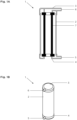
- Fig. 1A shows a cross section of a disposable filter unit 1 comprising an outer body 2, a top 3, a bottom 4, an inflow 5, an outflow 6 and a filter means 7 enclosed in the outer body.
- the inflow 5 is positioned adjacent to the bottom 4 and the outflow 6 is positioned adjacent to the top 3, and the inflow 5 and outflow 6 are arranged to be fixated simultaneously into a system 10 and released simultaneously from the system 10 enabling a simple replacing of the disposable filter unit 1 for a user.
- fig. 1B there is shown a disposable filter unit 1 in accordance with fig. 1 A , however in this case seen from the outside.
- FIG. 2 there is shown a cross section from above of a disposable filter unit 1 fixated into a docking station 15 of a system 10.
- the inflow 5 and outflow 6 comprise quick release connections 12, now when seen from above only seen as one connection.
- the system 10 comprises a mechanical filter fixating / releasing unit 8 ("release mechanism") with a release lever 9, intended to enable fixation and release of a disposable filter unit 1 into the docking station 15 of the system 10.
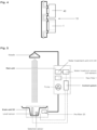
- FIG. 4 there is shown a part of a system 10 allowing for purification and recycling of water or separation of water, wherein said system comprises a combined water heater and water treatment device 40 which in terms of process flow is placed above a disposable filter unit 1 according to the present invention.
- the combined water heater and water treatment device 40 is placed in a vertically higher position than the disposable filter unit 1 the system 10.
- the water flow is directed to be fed into the bottom of the filter unit 1, fed through the filter unit 1 and out from the top of the same, then further into the combined heater and water treatment unit 40 at the bottom of the same to be treated and then finally after treatment fed out from the combined heater and water treatment unit 40 at the top thereof.
- the vertical positioning of the disposable filter unit 1 and combined heater and water treatment unit 40 in that order has several advantages.
- this arrangement enables a draining cycle of the filter unit 1, and also the combined heater and water treatment unit 40, by emptying water in the system from the top to the bottom by using gravity.
- a draining of the filter unit 1 also implies that the draining is performed from a cleaner part of the filter unit 1 to a dirtier side thereof, which also is beneficial.
- air in the system is transported the same direction. As such, there is no need to ventilate the system and there is minimal risk for air pockets.
- fig. 5 there is shown one example of a full system 10 allowing for purification and recycling of water or separation of water comprising a disposable filter unit 1 (here called main filter) according to the present invention.
- the system 10 is a shower.
- the pre-filter 20 is a mesh filter which is positioned in the drain unit 50 of the system 10.
- a water treatment unit 40 in this case a UV treatment unit.
- Different types of sensors and their connection to a control system are also shown in fig. 5 .
- FIG. 6 there is shown another specific embodiment of a disposable filter unit 1 according to the present invention.
- the filter unit 1 has two outflows in the top of the filter unit. This may be of interest to incorporate a ventilation channel in the main filter, inter alia intended for evacuation.
Landscapes
- Chemical & Material Sciences (AREA)
- Chemical Kinetics & Catalysis (AREA)
- Life Sciences & Earth Sciences (AREA)
- Hydrology & Water Resources (AREA)
- Engineering & Computer Science (AREA)
- Environmental & Geological Engineering (AREA)
- Water Supply & Treatment (AREA)
- Organic Chemistry (AREA)
- Physical Water Treatments (AREA)
Claims (12)
- System (10), das eine Reinigung und Wiederverwendung von Wasser oder eine Abscheidung von Wasser ermöglicht, wobei das System (10) ein Filtersystem umfasst, das ein erstes Filter (20), das ein entfernbares Maschenfilter ist, und ein zweites Filter, das eine Einwegfiltereinheit (1) ist, umfasst, wobei die Einwegfiltereinheit (1) einen Außenkörper (2), eine Oberseite (3), eine Unterseite (4), einen Zulauf (5), einen Ablauf (6) und ein Filtermittel (7) umfasst, das in dem Außenkörper (2) eingeschlossen ist, wobei die Einwegfiltereinheit (1) dadurch gekennzeichnet ist, dass der Zulauf (5) angrenzend an die Unterseite (4) positioniert ist und dass der Ablauf (6) angrenzend an die Oberseite (3) positioniert ist, und dass der Zulauf (5) und der Ablauf (6) dazu angeordnet sind, in dem System (10) befestigt und aus dem System (10) gelöst zu werden, was ein einfaches Austauschen der Einwegfiltereinheit (1) für einen Benutzer ermöglicht, wobei die Einwegfiltereinheit (1) in dem System (10) in einer vertikalen Richtung angeordnet ist, wobei sich die Oberseite (3) in einer höchsten Position der Einwegfiltereinheit (1) in dem System (10) befindet, und wobei das System (10) eine mechanische Filterbefestigungs-/-löseeinheit (8) umfasst, und wobei das System eine Wasserbehandlungs-UV-Einheit umfasst, die eine UV-Lampe und einen UV-Sensor umfasst.
- System (10) nach Anspruch 1, wobei der Zulauf (5) und der Ablauf (6) der Einwegfiltereinheit (1) Schnellverschlussverbindungen (12) umfassen.
- System (10) nach einem der Ansprüche 1 oder 2, wobei das Filtermittel (7) vollständig durch den Außenkörper (2), die Oberseite (3) und die Unterseite (4) eingeschlossen ist, so dass die Filtereinheit (1) als ein Druckbehälter fungiert.
- System (10) nach einem der Ansprüche 1-3, wobei die Einwegfiltereinheit (1) einen zusätzlichen Ablauf umfasst, der angrenzend an die Oberseite (3) positioniert ist und zum Entlüften der Einwegfiltereinheit (1) vorgesehen ist.
- System (10) nach einem der Ansprüche 1-4, wobei das entfernbare Maschenfilter (20) an einem Auslass (50) des Systems (10) angeordnet ist, der sich an oder in unmittelbarer Nähe zu einem Punkt einer Abscheidung von sauberem Wasser zur Wiederverwendung und verunreinigtem Wasser, das entsorgt werden soll, befindet.
- System (10) nach Anspruch 5, wobei die Wasserbehandlungseinheit (40) in einer Heizeinheit eingeschlossen ist.
- Verfahren zum Ermöglichen einer Reinigung und Wiederverwendung von Wasser oder einer Abscheidung von Wasser in einem System (10) nach einem der Ansprüche 1-6, wobei das Verfahren Folgendes umfasst:- einen ersten Schritt, der ein Auswahlschritt ist, bei dem sauberes Wasser gemäß einem festgelegten Wasserstandard in das System (10) zurückgeführt wird und verunreinigtes Wasser abgeschieden wird;- einen zweiten Schritt, der eine Grobfiltration ist, die unter Verwendung eines Vorfilters durchgeführt wird;- einen dritten Schritt, der eine Mittel- und Feinfiltration unter Verwendung eines Einweghauptfilters ist; und- einen vierten Schritt, der eine Wasserbehandlung unter Verwendung einer Wasserbehandlungseinheit ist; wobei das Vorfilter rückgespült wird, nachdem das System (10) verwendet wurde;wobei das System (10) entleert wird, nachdem das Vorfilter rückgespült wurde.
- Verfahren nach Anspruch 7, wobei das Verfahren kontinuierlich mit mehreren Schleifen und in Echtzeit durchgeführt wird.
- Verfahren nach einem der Ansprüche 7 oder 8, wobei die Wasserbehandlung eine UV-Behandlung ist.
- Verfahren nach einem der Ansprüche 7-9, wobei das Einweghauptfilter entleert wird, nachdem das System (10) verwendet wurde.
- Verfahren nach Anspruch 9 oder 10, wobei die UV-Behandlungseinheit entleert wird, nachdem das System (10) verwendet wurde.
- Verfahren nach einem der Ansprüche 7-11, wobei das Vorfilter an einem Auslass (50) des Systems (10) angeordnet ist, und wobei der Auslass (50) einen Abscheidungspunkt darstellt, an dem Wasser gemäß einem festgelegten Wasserstandard zurückgeführt wird oder verunreinigtes Wasser abgeschieden wird.
Applications Claiming Priority (2)
| Application Number | Priority Date | Filing Date | Title |
|---|---|---|---|
| SE1651549 | 2016-11-25 | ||
| PCT/SE2017/051156 WO2018097787A1 (en) | 2016-11-25 | 2017-11-22 | Disposable filter unit for a system allowing for purification and recycling of water or separation of water |
Publications (4)
| Publication Number | Publication Date |
|---|---|
| EP3545138A1 EP3545138A1 (de) | 2019-10-02 |
| EP3545138A4 EP3545138A4 (de) | 2020-07-15 |
| EP3545138C0 EP3545138C0 (de) | 2025-04-02 |
| EP3545138B1 true EP3545138B1 (de) | 2025-04-02 |
Family
ID=62196216
Family Applications (1)
| Application Number | Title | Priority Date | Filing Date |
|---|---|---|---|
| EP17874312.6A Active EP3545138B1 (de) | 2016-11-25 | 2017-11-22 | Einweg-filtereinheit in einem system zur reinigung und zum recycling von wasser |
Country Status (3)
| Country | Link |
|---|---|
| US (1) | US11452951B2 (de) |
| EP (1) | EP3545138B1 (de) |
| WO (1) | WO2018097787A1 (de) |
Families Citing this family (5)
| Publication number | Priority date | Publication date | Assignee | Title |
|---|---|---|---|---|
| EP3545143B1 (de) * | 2016-11-25 | 2022-10-19 | Orbital Systems AB | Abfluss für eine wasserrecyclingvorrichtung |
| CN110023247A (zh) * | 2016-11-25 | 2019-07-16 | 轨道系统公司 | 用于允许水净化和再循环或水分离的系统的传感器系统 |
| IT201800011133A1 (it) * | 2018-12-14 | 2020-06-14 | Mazzei Marco | Sistema sanitario antispreco |
| US12421134B2 (en) * | 2020-06-26 | 2025-09-23 | Orbital Systems Ab | System for water quality measurement and a recirculation system comprising the same |
| SE546551C2 (en) * | 2022-10-06 | 2024-11-26 | Mimbly Ab | Water recycling device with filtration tank |
Citations (1)
| Publication number | Priority date | Publication date | Assignee | Title |
|---|---|---|---|---|
| US20150344323A1 (en) * | 2011-12-23 | 2015-12-03 | Orbital Systems Ab | Device and method for purifying and recycling shower water |
Family Cites Families (12)
| Publication number | Priority date | Publication date | Assignee | Title |
|---|---|---|---|---|
| DE2263412A1 (de) * | 1972-12-27 | 1974-07-04 | Rolf Hensel | Vorrichtung zum aufbereiten von fluessigkeiten, insb. des trinkwassers auf schiffen |
| US5192427A (en) | 1990-05-24 | 1993-03-09 | Douglas R. Eger | Shower filters and accessories |
| US5147532A (en) * | 1991-02-21 | 1992-09-15 | Leek Jr Kenneth F | Domestic grey water purifier using diverter and UV filter treater with preheater |
| TW264536B (en) | 1995-01-13 | 1995-12-01 | Ziba Design Inc | Readily serviceable ancillary fluid filtration system having visual flow rate indicator and quick-release fluid hose fitting |
| DE19848389C2 (de) * | 1998-10-21 | 2002-06-06 | Sartorius Gmbh | Capsule zur Filtration von Fluiden |
| JP2001107428A (ja) | 1999-10-12 | 2001-04-17 | Kankyo Forum Kk | 洗浄便器の浄水器 |
| US20040222141A1 (en) * | 2001-02-13 | 2004-11-11 | Gray Buddy Don | Dental mercury abatement system |
| WO2003084882A1 (en) * | 2002-04-04 | 2003-10-16 | Millipore Corporation | Composite water filter |
| DE102011081054A1 (de) * | 2011-08-16 | 2013-02-21 | BSH Bosch und Siemens Hausgeräte GmbH | Wasserbereiter |
| CN104556271A (zh) | 2013-10-23 | 2015-04-29 | 宁波市万泓电器科技有限公司 | 一种带紫外线杀菌功能的加热装置 |
| KR20160053225A (ko) | 2014-10-31 | 2016-05-13 | 서울바이오시스 주식회사 | Uvled를 이용한 살균 샤워기 |
| WO2016144235A1 (en) | 2015-03-09 | 2016-09-15 | Orbital Systems Ab | Capsule intended for a liquid flow comprising an inner casing and an outer unit |
-
2017
- 2017-11-22 EP EP17874312.6A patent/EP3545138B1/de active Active
- 2017-11-22 US US16/462,855 patent/US11452951B2/en active Active
- 2017-11-22 WO PCT/SE2017/051156 patent/WO2018097787A1/en not_active Ceased
Patent Citations (1)
| Publication number | Priority date | Publication date | Assignee | Title |
|---|---|---|---|---|
| US20150344323A1 (en) * | 2011-12-23 | 2015-12-03 | Orbital Systems Ab | Device and method for purifying and recycling shower water |
Also Published As
| Publication number | Publication date |
|---|---|
| EP3545138A1 (de) | 2019-10-02 |
| US20190275449A1 (en) | 2019-09-12 |
| EP3545138C0 (de) | 2025-04-02 |
| EP3545138A4 (de) | 2020-07-15 |
| WO2018097787A1 (en) | 2018-05-31 |
| US11452951B2 (en) | 2022-09-27 |
Similar Documents
| Publication | Publication Date | Title |
|---|---|---|
| EP3545138B1 (de) | Einweg-filtereinheit in einem system zur reinigung und zum recycling von wasser | |
| US12337266B2 (en) | Filter device for a water-bearing domestic appliance, a water-bearing domestic appliance with a filter device and a method for filtering water with a filter device | |
| CA3102361A1 (en) | Method and apparatus for treating commercial and industrial laundry wastewater | |
| KR101610593B1 (ko) | 공동주택의 음식물쓰레기집중처리기 | |
| KR101135951B1 (ko) | 정수기의 자가세정방법 | |
| KR20140126894A (ko) | 정수기의 자동 살균 세척 시스템 및 방법 | |
| KR100199338B1 (ko) | 역삼투 냉,온 정수기의 음용수 취출장치 | |
| KR20230121234A (ko) | 여과 장치 | |
| UA129993C2 (uk) | Водяний фільтр для акваріума | |
| JP5757461B2 (ja) | 浴場設備 | |
| KR20100078036A (ko) | 교체 가능한 필터를 갖는 수족관 정수장치 | |
| CN106006770A (zh) | 带有净水自动更新功能的净水机及其控制方法 | |
| CN102380317A (zh) | 一种提高超滤膜化学清洗效果的方法 | |
| US20200299152A1 (en) | Combined water heater and water treatment unit | |
| JP2011020068A (ja) | 排水浄化装置 | |
| KR101551385B1 (ko) | 설치가 용이한 수처리 여과장치 | |
| JP2023545613A (ja) | 航空機のための流体リサイクルユニット | |
| WO2016144235A1 (en) | Capsule intended for a liquid flow comprising an inner casing and an outer unit | |
| CN209771554U (zh) | 一种可确认净水系统滤网使用寿命的净水装置 | |
| KR101549642B1 (ko) | 조립형 프리필터 | |
| JP7316492B2 (ja) | 水処理装置 | |
| JPH09290252A (ja) | 逆滲透冷・温浄水器の浄水及び循環システム | |
| CN208791385U (zh) | 一种多元一体水处理设备 | |
| KR20250059801A (ko) | 제약회사 폐수 처리용 정밀여과장치 | |
| US10072404B2 (en) | Solid food waste material collection device |
Legal Events
| Date | Code | Title | Description |
|---|---|---|---|
| STAA | Information on the status of an ep patent application or granted ep patent |
Free format text: STATUS: THE INTERNATIONAL PUBLICATION HAS BEEN MADE |
|
| PUAI | Public reference made under article 153(3) epc to a published international application that has entered the european phase |
Free format text: ORIGINAL CODE: 0009012 |
|
| STAA | Information on the status of an ep patent application or granted ep patent |
Free format text: STATUS: REQUEST FOR EXAMINATION WAS MADE |
|
| 17P | Request for examination filed |
Effective date: 20190624 |
|
| AK | Designated contracting states |
Kind code of ref document: A1 Designated state(s): AL AT BE BG CH CY CZ DE DK EE ES FI FR GB GR HR HU IE IS IT LI LT LU LV MC MK MT NL NO PL PT RO RS SE SI SK SM TR |
|
| AX | Request for extension of the european patent |
Extension state: BA ME |
|
| DAV | Request for validation of the european patent (deleted) | ||
| DAX | Request for extension of the european patent (deleted) | ||
| A4 | Supplementary search report drawn up and despatched |
Effective date: 20200617 |
|
| RIC1 | Information provided on ipc code assigned before grant |
Ipc: E03B 1/04 20060101AFI20200610BHEP Ipc: E03C 1/00 20060101ALI20200610BHEP Ipc: E03B 1/02 20060101ALI20200610BHEP Ipc: B01D 35/02 20060101ALI20200610BHEP Ipc: B01D 27/14 20060101ALI20200610BHEP Ipc: C02F 1/32 20060101ALN20200610BHEP Ipc: C02F 9/00 20060101ALI20200610BHEP Ipc: B01D 27/00 20060101ALI20200610BHEP Ipc: A47K 3/28 20060101ALI20200610BHEP |
|
| STAA | Information on the status of an ep patent application or granted ep patent |
Free format text: STATUS: EXAMINATION IS IN PROGRESS |
|
| 17Q | First examination report despatched |
Effective date: 20220706 |
|
| RIC1 | Information provided on ipc code assigned before grant |
Ipc: C02F 1/32 20060101ALN20240912BHEP Ipc: C02F 9/00 20060101ALI20240912BHEP Ipc: B01D 35/02 20060101ALI20240912BHEP Ipc: B01D 27/14 20060101ALI20240912BHEP Ipc: B01D 27/00 20060101ALI20240912BHEP Ipc: A47K 3/28 20060101ALI20240912BHEP Ipc: E03C 1/00 20060101ALI20240912BHEP Ipc: E03B 1/02 20060101ALI20240912BHEP Ipc: E03B 1/04 20060101AFI20240912BHEP |
|
| RIC1 | Information provided on ipc code assigned before grant |
Ipc: C02F 1/32 20060101ALN20240913BHEP Ipc: C02F 9/00 20060101ALI20240913BHEP Ipc: B01D 35/02 20060101ALI20240913BHEP Ipc: B01D 27/14 20060101ALI20240913BHEP Ipc: B01D 27/00 20060101ALI20240913BHEP Ipc: A47K 3/28 20060101ALI20240913BHEP Ipc: E03C 1/00 20060101ALI20240913BHEP Ipc: E03B 1/02 20060101ALI20240913BHEP Ipc: E03B 1/04 20060101AFI20240913BHEP |
|
| GRAP | Despatch of communication of intention to grant a patent |
Free format text: ORIGINAL CODE: EPIDOSNIGR1 |
|
| STAA | Information on the status of an ep patent application or granted ep patent |
Free format text: STATUS: GRANT OF PATENT IS INTENDED |
|
| RIC1 | Information provided on ipc code assigned before grant |
Ipc: C02F 1/32 20060101ALN20241010BHEP Ipc: C02F 9/00 20060101ALI20241010BHEP Ipc: B01D 35/02 20060101ALI20241010BHEP Ipc: B01D 27/14 20060101ALI20241010BHEP Ipc: B01D 27/00 20060101ALI20241010BHEP Ipc: A47K 3/28 20060101ALI20241010BHEP Ipc: E03C 1/00 20060101ALI20241010BHEP Ipc: E03B 1/02 20060101ALI20241010BHEP Ipc: E03B 1/04 20060101AFI20241010BHEP |
|
| INTG | Intention to grant announced |
Effective date: 20241028 |
|
| GRAS | Grant fee paid |
Free format text: ORIGINAL CODE: EPIDOSNIGR3 |
|
| GRAA | (expected) grant |
Free format text: ORIGINAL CODE: 0009210 |
|
| STAA | Information on the status of an ep patent application or granted ep patent |
Free format text: STATUS: THE PATENT HAS BEEN GRANTED |
|
| AK | Designated contracting states |
Kind code of ref document: B1 Designated state(s): AL AT BE BG CH CY CZ DE DK EE ES FI FR GB GR HR HU IE IS IT LI LT LU LV MC MK MT NL NO PL PT RO RS SE SI SK SM TR |
|
| REG | Reference to a national code |
Ref country code: GB Ref legal event code: FG4D |
|
| REG | Reference to a national code |
Ref country code: CH Ref legal event code: EP |
|
| REG | Reference to a national code |
Ref country code: IE Ref legal event code: FG4D |
|
| REG | Reference to a national code |
Ref country code: DE Ref legal event code: R096 Ref document number: 602017088742 Country of ref document: DE |
|
| U01 | Request for unitary effect filed |
Effective date: 20250430 |
|
| RAP4 | Party data changed (patent owner data changed or rights of a patent transferred) |
Owner name: ORBITAL SYSTEMS AB |
|
| U07 | Unitary effect registered |
Designated state(s): AT BE BG DE DK EE FI FR IT LT LU LV MT NL PT RO SE SI Effective date: 20250528 |
|
| PG25 | Lapsed in a contracting state [announced via postgrant information from national office to epo] |
Ref country code: ES Free format text: LAPSE BECAUSE OF FAILURE TO SUBMIT A TRANSLATION OF THE DESCRIPTION OR TO PAY THE FEE WITHIN THE PRESCRIBED TIME-LIMIT Effective date: 20250402 |
|
| PG25 | Lapsed in a contracting state [announced via postgrant information from national office to epo] |
Ref country code: NO Free format text: LAPSE BECAUSE OF FAILURE TO SUBMIT A TRANSLATION OF THE DESCRIPTION OR TO PAY THE FEE WITHIN THE PRESCRIBED TIME-LIMIT Effective date: 20250702 Ref country code: GR Free format text: LAPSE BECAUSE OF FAILURE TO SUBMIT A TRANSLATION OF THE DESCRIPTION OR TO PAY THE FEE WITHIN THE PRESCRIBED TIME-LIMIT Effective date: 20250703 |
|
| PG25 | Lapsed in a contracting state [announced via postgrant information from national office to epo] |
Ref country code: PL Free format text: LAPSE BECAUSE OF FAILURE TO SUBMIT A TRANSLATION OF THE DESCRIPTION OR TO PAY THE FEE WITHIN THE PRESCRIBED TIME-LIMIT Effective date: 20250402 |
|
| PG25 | Lapsed in a contracting state [announced via postgrant information from national office to epo] |
Ref country code: HR Free format text: LAPSE BECAUSE OF FAILURE TO SUBMIT A TRANSLATION OF THE DESCRIPTION OR TO PAY THE FEE WITHIN THE PRESCRIBED TIME-LIMIT Effective date: 20250402 |
|
| PG25 | Lapsed in a contracting state [announced via postgrant information from national office to epo] |
Ref country code: RS Free format text: LAPSE BECAUSE OF FAILURE TO SUBMIT A TRANSLATION OF THE DESCRIPTION OR TO PAY THE FEE WITHIN THE PRESCRIBED TIME-LIMIT Effective date: 20250702 |
|
| PG25 | Lapsed in a contracting state [announced via postgrant information from national office to epo] |
Ref country code: IS Free format text: LAPSE BECAUSE OF FAILURE TO SUBMIT A TRANSLATION OF THE DESCRIPTION OR TO PAY THE FEE WITHIN THE PRESCRIBED TIME-LIMIT Effective date: 20250802 |
|
| U20 | Renewal fee for the european patent with unitary effect paid |
Year of fee payment: 9 Effective date: 20251030 |
|
| PG25 | Lapsed in a contracting state [announced via postgrant information from national office to epo] |
Ref country code: SM Free format text: LAPSE BECAUSE OF FAILURE TO SUBMIT A TRANSLATION OF THE DESCRIPTION OR TO PAY THE FEE WITHIN THE PRESCRIBED TIME-LIMIT Effective date: 20250402 |
|
| PG25 | Lapsed in a contracting state [announced via postgrant information from national office to epo] |
Ref country code: CZ Free format text: LAPSE BECAUSE OF FAILURE TO SUBMIT A TRANSLATION OF THE DESCRIPTION OR TO PAY THE FEE WITHIN THE PRESCRIBED TIME-LIMIT Effective date: 20250402 |
|
| PG25 | Lapsed in a contracting state [announced via postgrant information from national office to epo] |
Ref country code: SK Free format text: LAPSE BECAUSE OF FAILURE TO SUBMIT A TRANSLATION OF THE DESCRIPTION OR TO PAY THE FEE WITHIN THE PRESCRIBED TIME-LIMIT Effective date: 20250402 |
|
| PLBE | No opposition filed within time limit |
Free format text: ORIGINAL CODE: 0009261 |
|
| STAA | Information on the status of an ep patent application or granted ep patent |
Free format text: STATUS: NO OPPOSITION FILED WITHIN TIME LIMIT |
|
| REG | Reference to a national code |
Ref country code: CH Ref legal event code: L10 Free format text: ST27 STATUS EVENT CODE: U-0-0-L10-L00 (AS PROVIDED BY THE NATIONAL OFFICE) Effective date: 20260211 |