EP3544810B1 - Verfahren zur lamination einer verbundscheibe - Google Patents
Verfahren zur lamination einer verbundscheibe Download PDFInfo
- Publication number
- EP3544810B1 EP3544810B1 EP17798186.7A EP17798186A EP3544810B1 EP 3544810 B1 EP3544810 B1 EP 3544810B1 EP 17798186 A EP17798186 A EP 17798186A EP 3544810 B1 EP3544810 B1 EP 3544810B1
- Authority
- EP
- European Patent Office
- Prior art keywords
- vacuum
- stack sequence
- temperature
- equal
- bar
- Prior art date
- Legal status (The legal status is an assumption and is not a legal conclusion. Google has not performed a legal analysis and makes no representation as to the accuracy of the status listed.)
- Active
Links
- 238000000034 method Methods 0.000 title claims description 90
- 238000003475 lamination Methods 0.000 title description 12
- 239000002131 composite material Substances 0.000 claims description 30
- 239000000758 substrate Substances 0.000 claims description 30
- 230000008569 process Effects 0.000 claims description 23
- 229920002037 poly(vinyl butyral) polymer Polymers 0.000 claims description 15
- 230000005855 radiation Effects 0.000 claims description 13
- 238000001816 cooling Methods 0.000 claims description 12
- XLYOFNOQVPJJNP-UHFFFAOYSA-N water Substances O XLYOFNOQVPJJNP-UHFFFAOYSA-N 0.000 claims description 9
- 238000010438 heat treatment Methods 0.000 claims description 7
- -1 polyethylene Polymers 0.000 claims description 7
- 239000004698 Polyethylene Substances 0.000 claims description 4
- 239000004743 Polypropylene Substances 0.000 claims description 4
- 229920000573 polyethylene Polymers 0.000 claims description 4
- 229920001155 polypropylene Polymers 0.000 claims description 4
- 239000011521 glass Substances 0.000 claims description 3
- 238000010030 laminating Methods 0.000 claims description 3
- 239000000203 mixture Substances 0.000 claims description 3
- 229920003229 poly(methyl methacrylate) Polymers 0.000 claims description 3
- 239000004417 polycarbonate Substances 0.000 claims description 3
- 229920000515 polycarbonate Polymers 0.000 claims description 3
- 239000004926 polymethyl methacrylate Substances 0.000 claims description 3
- 239000005361 soda-lime glass Substances 0.000 claims description 3
- VYPSYNLAJGMNEJ-UHFFFAOYSA-N Silicium dioxide Chemical compound O=[Si]=O VYPSYNLAJGMNEJ-UHFFFAOYSA-N 0.000 claims description 2
- 239000005388 borosilicate glass Substances 0.000 claims description 2
- 239000005357 flat glass Substances 0.000 claims description 2
- 239000005329 float glass Substances 0.000 claims description 2
- 229920000642 polymer Polymers 0.000 claims 1
- 239000010410 layer Substances 0.000 description 53
- 230000032258 transport Effects 0.000 description 20
- 239000002346 layers by function Substances 0.000 description 10
- 238000013022 venting Methods 0.000 description 6
- 230000005540 biological transmission Effects 0.000 description 5
- XLOMVQKBTHCTTD-UHFFFAOYSA-N Zinc monoxide Chemical compound [Zn]=O XLOMVQKBTHCTTD-UHFFFAOYSA-N 0.000 description 4
- 238000010586 diagram Methods 0.000 description 4
- 238000004519 manufacturing process Methods 0.000 description 4
- 229910052751 metal Inorganic materials 0.000 description 4
- 239000002184 metal Substances 0.000 description 4
- 229920003023 plastic Polymers 0.000 description 4
- 239000004033 plastic Substances 0.000 description 4
- 238000011161 development Methods 0.000 description 3
- 239000012799 electrically-conductive coating Substances 0.000 description 3
- 229910052709 silver Inorganic materials 0.000 description 3
- 239000004332 silver Substances 0.000 description 3
- 230000003595 spectral effect Effects 0.000 description 3
- 229920001169 thermoplastic Polymers 0.000 description 3
- 239000004416 thermosoftening plastic Substances 0.000 description 3
- PXHVJJICTQNCMI-UHFFFAOYSA-N Nickel Chemical compound [Ni] PXHVJJICTQNCMI-UHFFFAOYSA-N 0.000 description 2
- 230000009471 action Effects 0.000 description 2
- 230000015572 biosynthetic process Effects 0.000 description 2
- 238000005229 chemical vapour deposition Methods 0.000 description 2
- 239000003989 dielectric material Substances 0.000 description 2
- 238000011835 investigation Methods 0.000 description 2
- 229910001092 metal group alloy Inorganic materials 0.000 description 2
- 238000005240 physical vapour deposition Methods 0.000 description 2
- 229920000139 polyethylene terephthalate Polymers 0.000 description 2
- 239000005020 polyethylene terephthalate Substances 0.000 description 2
- 239000004800 polyvinyl chloride Substances 0.000 description 2
- 229920000915 polyvinyl chloride Polymers 0.000 description 2
- 229920005989 resin Polymers 0.000 description 2
- 239000011347 resin Substances 0.000 description 2
- 238000004544 sputter deposition Methods 0.000 description 2
- 239000011787 zinc oxide Substances 0.000 description 2
- VYZAMTAEIAYCRO-UHFFFAOYSA-N Chromium Chemical compound [Cr] VYZAMTAEIAYCRO-UHFFFAOYSA-N 0.000 description 1
- RYGMFSIKBFXOCR-UHFFFAOYSA-N Copper Chemical compound [Cu] RYGMFSIKBFXOCR-UHFFFAOYSA-N 0.000 description 1
- 241001115479 Opheodrys Species 0.000 description 1
- 239000004952 Polyamide Substances 0.000 description 1
- 239000004793 Polystyrene Substances 0.000 description 1
- 229910052581 Si3N4 Inorganic materials 0.000 description 1
- BQCADISMDOOEFD-UHFFFAOYSA-N Silver Chemical compound [Ag] BQCADISMDOOEFD-UHFFFAOYSA-N 0.000 description 1
- 229910006404 SnO 2 Inorganic materials 0.000 description 1
- 238000010521 absorption reaction Methods 0.000 description 1
- 150000001252 acrylic acid derivatives Chemical class 0.000 description 1
- 230000006978 adaptation Effects 0.000 description 1
- 229910045601 alloy Inorganic materials 0.000 description 1
- 239000000956 alloy Substances 0.000 description 1
- 238000010923 batch production Methods 0.000 description 1
- 230000008901 benefit Effects 0.000 description 1
- 238000005266 casting Methods 0.000 description 1
- 239000000919 ceramic Substances 0.000 description 1
- 229910052804 chromium Inorganic materials 0.000 description 1
- 239000011651 chromium Substances 0.000 description 1
- 239000011248 coating agent Substances 0.000 description 1
- 238000000576 coating method Methods 0.000 description 1
- 238000010276 construction Methods 0.000 description 1
- 229910052802 copper Inorganic materials 0.000 description 1
- 239000010949 copper Substances 0.000 description 1
- 238000005137 deposition process Methods 0.000 description 1
- 230000000694 effects Effects 0.000 description 1
- 229920001971 elastomer Polymers 0.000 description 1
- 230000005670 electromagnetic radiation Effects 0.000 description 1
- 238000005516 engineering process Methods 0.000 description 1
- QHSJIZLJUFMIFP-UHFFFAOYSA-N ethene;1,1,2,2-tetrafluoroethene Chemical group C=C.FC(F)=C(F)F QHSJIZLJUFMIFP-UHFFFAOYSA-N 0.000 description 1
- HQQADJVZYDDRJT-UHFFFAOYSA-N ethene;prop-1-ene Chemical class C=C.CC=C HQQADJVZYDDRJT-UHFFFAOYSA-N 0.000 description 1
- 229920001038 ethylene copolymer Polymers 0.000 description 1
- 229920000840 ethylene tetrafluoroethylene copolymer Polymers 0.000 description 1
- 239000005038 ethylene vinyl acetate Substances 0.000 description 1
- 239000011888 foil Substances 0.000 description 1
- 239000003292 glue Substances 0.000 description 1
- PCHJSUWPFVWCPO-UHFFFAOYSA-N gold Chemical compound [Au] PCHJSUWPFVWCPO-UHFFFAOYSA-N 0.000 description 1
- 229910052737 gold Inorganic materials 0.000 description 1
- 239000010931 gold Substances 0.000 description 1
- 238000009499 grossing Methods 0.000 description 1
- AMGQUBHHOARCQH-UHFFFAOYSA-N indium;oxotin Chemical compound [In].[Sn]=O AMGQUBHHOARCQH-UHFFFAOYSA-N 0.000 description 1
- 239000000463 material Substances 0.000 description 1
- 238000005259 measurement Methods 0.000 description 1
- 229910052759 nickel Inorganic materials 0.000 description 1
- 150000004767 nitrides Chemical class 0.000 description 1
- TWNQGVIAIRXVLR-UHFFFAOYSA-N oxo(oxoalumanyloxy)alumane Chemical compound O=[Al]O[Al]=O TWNQGVIAIRXVLR-UHFFFAOYSA-N 0.000 description 1
- 229920009441 perflouroethylene propylene Polymers 0.000 description 1
- 229920000058 polyacrylate Polymers 0.000 description 1
- 229920002647 polyamide Polymers 0.000 description 1
- 229920000728 polyester Polymers 0.000 description 1
- 229920002223 polystyrene Polymers 0.000 description 1
- 239000004814 polyurethane Substances 0.000 description 1
- 229920002620 polyvinyl fluoride Polymers 0.000 description 1
- 238000012545 processing Methods 0.000 description 1
- 230000009467 reduction Effects 0.000 description 1
- 230000000717 retained effect Effects 0.000 description 1
- 239000005060 rubber Substances 0.000 description 1
- HQVNEWCFYHHQES-UHFFFAOYSA-N silicon nitride Chemical compound N12[Si]34N5[Si]62N3[Si]51N64 HQVNEWCFYHHQES-UHFFFAOYSA-N 0.000 description 1
- 239000002356 single layer Substances 0.000 description 1
- XOLBLPGZBRYERU-UHFFFAOYSA-N tin dioxide Chemical compound O=[Sn]=O XOLBLPGZBRYERU-UHFFFAOYSA-N 0.000 description 1
- 229910001887 tin oxide Inorganic materials 0.000 description 1
- 230000007723 transport mechanism Effects 0.000 description 1
- 238000007738 vacuum evaporation Methods 0.000 description 1
- 238000009423 ventilation Methods 0.000 description 1
Images


Classifications
-
- B—PERFORMING OPERATIONS; TRANSPORTING
- B32—LAYERED PRODUCTS
- B32B—LAYERED PRODUCTS, i.e. PRODUCTS BUILT-UP OF STRATA OF FLAT OR NON-FLAT, e.g. CELLULAR OR HONEYCOMB, FORM
- B32B17/00—Layered products essentially comprising sheet glass, or glass, slag, or like fibres
- B32B17/06—Layered products essentially comprising sheet glass, or glass, slag, or like fibres comprising glass as the main or only constituent of a layer, next to another layer of a specific material
- B32B17/10—Layered products essentially comprising sheet glass, or glass, slag, or like fibres comprising glass as the main or only constituent of a layer, next to another layer of a specific material of synthetic resin
- B32B17/10005—Layered products essentially comprising sheet glass, or glass, slag, or like fibres comprising glass as the main or only constituent of a layer, next to another layer of a specific material of synthetic resin laminated safety glass or glazing
- B32B17/10009—Layered products essentially comprising sheet glass, or glass, slag, or like fibres comprising glass as the main or only constituent of a layer, next to another layer of a specific material of synthetic resin laminated safety glass or glazing characterized by the number, the constitution or treatment of glass sheets
- B32B17/10036—Layered products essentially comprising sheet glass, or glass, slag, or like fibres comprising glass as the main or only constituent of a layer, next to another layer of a specific material of synthetic resin laminated safety glass or glazing characterized by the number, the constitution or treatment of glass sheets comprising two outer glass sheets
-
- B—PERFORMING OPERATIONS; TRANSPORTING
- B32—LAYERED PRODUCTS
- B32B—LAYERED PRODUCTS, i.e. PRODUCTS BUILT-UP OF STRATA OF FLAT OR NON-FLAT, e.g. CELLULAR OR HONEYCOMB, FORM
- B32B17/00—Layered products essentially comprising sheet glass, or glass, slag, or like fibres
- B32B17/06—Layered products essentially comprising sheet glass, or glass, slag, or like fibres comprising glass as the main or only constituent of a layer, next to another layer of a specific material
- B32B17/10—Layered products essentially comprising sheet glass, or glass, slag, or like fibres comprising glass as the main or only constituent of a layer, next to another layer of a specific material of synthetic resin
- B32B17/10005—Layered products essentially comprising sheet glass, or glass, slag, or like fibres comprising glass as the main or only constituent of a layer, next to another layer of a specific material of synthetic resin laminated safety glass or glazing
- B32B17/10165—Functional features of the laminated safety glass or glazing
- B32B17/10174—Coatings of a metallic or dielectric material on a constituent layer of glass or polymer
-
- B—PERFORMING OPERATIONS; TRANSPORTING
- B32—LAYERED PRODUCTS
- B32B—LAYERED PRODUCTS, i.e. PRODUCTS BUILT-UP OF STRATA OF FLAT OR NON-FLAT, e.g. CELLULAR OR HONEYCOMB, FORM
- B32B17/00—Layered products essentially comprising sheet glass, or glass, slag, or like fibres
- B32B17/06—Layered products essentially comprising sheet glass, or glass, slag, or like fibres comprising glass as the main or only constituent of a layer, next to another layer of a specific material
- B32B17/10—Layered products essentially comprising sheet glass, or glass, slag, or like fibres comprising glass as the main or only constituent of a layer, next to another layer of a specific material of synthetic resin
- B32B17/10005—Layered products essentially comprising sheet glass, or glass, slag, or like fibres comprising glass as the main or only constituent of a layer, next to another layer of a specific material of synthetic resin laminated safety glass or glazing
- B32B17/1055—Layered products essentially comprising sheet glass, or glass, slag, or like fibres comprising glass as the main or only constituent of a layer, next to another layer of a specific material of synthetic resin laminated safety glass or glazing characterized by the resin layer, i.e. interlayer
- B32B17/10559—Shape of the cross-section
- B32B17/10577—Surface roughness
-
- B—PERFORMING OPERATIONS; TRANSPORTING
- B32—LAYERED PRODUCTS
- B32B—LAYERED PRODUCTS, i.e. PRODUCTS BUILT-UP OF STRATA OF FLAT OR NON-FLAT, e.g. CELLULAR OR HONEYCOMB, FORM
- B32B17/00—Layered products essentially comprising sheet glass, or glass, slag, or like fibres
- B32B17/06—Layered products essentially comprising sheet glass, or glass, slag, or like fibres comprising glass as the main or only constituent of a layer, next to another layer of a specific material
- B32B17/10—Layered products essentially comprising sheet glass, or glass, slag, or like fibres comprising glass as the main or only constituent of a layer, next to another layer of a specific material of synthetic resin
- B32B17/10005—Layered products essentially comprising sheet glass, or glass, slag, or like fibres comprising glass as the main or only constituent of a layer, next to another layer of a specific material of synthetic resin laminated safety glass or glazing
- B32B17/1055—Layered products essentially comprising sheet glass, or glass, slag, or like fibres comprising glass as the main or only constituent of a layer, next to another layer of a specific material of synthetic resin laminated safety glass or glazing characterized by the resin layer, i.e. interlayer
- B32B17/10761—Layered products essentially comprising sheet glass, or glass, slag, or like fibres comprising glass as the main or only constituent of a layer, next to another layer of a specific material of synthetic resin laminated safety glass or glazing characterized by the resin layer, i.e. interlayer containing vinyl acetal
-
- B—PERFORMING OPERATIONS; TRANSPORTING
- B32—LAYERED PRODUCTS
- B32B—LAYERED PRODUCTS, i.e. PRODUCTS BUILT-UP OF STRATA OF FLAT OR NON-FLAT, e.g. CELLULAR OR HONEYCOMB, FORM
- B32B17/00—Layered products essentially comprising sheet glass, or glass, slag, or like fibres
- B32B17/06—Layered products essentially comprising sheet glass, or glass, slag, or like fibres comprising glass as the main or only constituent of a layer, next to another layer of a specific material
- B32B17/10—Layered products essentially comprising sheet glass, or glass, slag, or like fibres comprising glass as the main or only constituent of a layer, next to another layer of a specific material of synthetic resin
- B32B17/10005—Layered products essentially comprising sheet glass, or glass, slag, or like fibres comprising glass as the main or only constituent of a layer, next to another layer of a specific material of synthetic resin laminated safety glass or glazing
- B32B17/10807—Making laminated safety glass or glazing; Apparatus therefor
- B32B17/10816—Making laminated safety glass or glazing; Apparatus therefor by pressing
- B32B17/10825—Isostatic pressing, i.e. using non rigid pressure-exerting members against rigid parts
- B32B17/10834—Isostatic pressing, i.e. using non rigid pressure-exerting members against rigid parts using a fluid
- B32B17/10844—Isostatic pressing, i.e. using non rigid pressure-exerting members against rigid parts using a fluid using a membrane between the layered product and the fluid
-
- B—PERFORMING OPERATIONS; TRANSPORTING
- B32—LAYERED PRODUCTS
- B32B—LAYERED PRODUCTS, i.e. PRODUCTS BUILT-UP OF STRATA OF FLAT OR NON-FLAT, e.g. CELLULAR OR HONEYCOMB, FORM
- B32B17/00—Layered products essentially comprising sheet glass, or glass, slag, or like fibres
- B32B17/06—Layered products essentially comprising sheet glass, or glass, slag, or like fibres comprising glass as the main or only constituent of a layer, next to another layer of a specific material
- B32B17/10—Layered products essentially comprising sheet glass, or glass, slag, or like fibres comprising glass as the main or only constituent of a layer, next to another layer of a specific material of synthetic resin
- B32B17/10005—Layered products essentially comprising sheet glass, or glass, slag, or like fibres comprising glass as the main or only constituent of a layer, next to another layer of a specific material of synthetic resin laminated safety glass or glazing
- B32B17/10807—Making laminated safety glass or glazing; Apparatus therefor
- B32B17/10816—Making laminated safety glass or glazing; Apparatus therefor by pressing
- B32B17/10871—Making laminated safety glass or glazing; Apparatus therefor by pressing in combination with particular heat treatment
-
- B—PERFORMING OPERATIONS; TRANSPORTING
- B32—LAYERED PRODUCTS
- B32B—LAYERED PRODUCTS, i.e. PRODUCTS BUILT-UP OF STRATA OF FLAT OR NON-FLAT, e.g. CELLULAR OR HONEYCOMB, FORM
- B32B17/00—Layered products essentially comprising sheet glass, or glass, slag, or like fibres
- B32B17/06—Layered products essentially comprising sheet glass, or glass, slag, or like fibres comprising glass as the main or only constituent of a layer, next to another layer of a specific material
- B32B17/10—Layered products essentially comprising sheet glass, or glass, slag, or like fibres comprising glass as the main or only constituent of a layer, next to another layer of a specific material of synthetic resin
- B32B17/10005—Layered products essentially comprising sheet glass, or glass, slag, or like fibres comprising glass as the main or only constituent of a layer, next to another layer of a specific material of synthetic resin laminated safety glass or glazing
- B32B17/10807—Making laminated safety glass or glazing; Apparatus therefor
- B32B17/1099—After-treatment of the layered product, e.g. cooling
-
- F—MECHANICAL ENGINEERING; LIGHTING; HEATING; WEAPONS; BLASTING
- F27—FURNACES; KILNS; OVENS; RETORTS
- F27B—FURNACES, KILNS, OVENS OR RETORTS IN GENERAL; OPEN SINTERING OR LIKE APPARATUS
- F27B17/00—Furnaces of a kind not covered by any of groups F27B1/00 - F27B15/00
Definitions
- the invention relates to a method for lamination of a composite pane and in particular to an autoclave-free method and a device for carrying out the method according to the invention.
- Composite windows are widely used, for example as vehicle windows such as windshields, side windows, rear windows or roof windows in vehicles on water, on land or in the air, but also as architectural windows, as fire protection windows, as safety glazing or in furniture as well as movable or fixed furnishings.
- Composite panes typically comprise two panes, for example a substrate pane and a cover pane, which are connected to one another via an intermediate layer, for example made of a thermoplastic polyvinyl butyral (PVB) film, in a lamination process under the action of heat and pressure.
- PVB thermoplastic polyvinyl butyral
- the object of the present invention is now to provide an improved method for lamination of a composite pane, and in particular an autoclave-free method, which makes it possible to manufacture composite panes of high quality cost-effectively.
- the method according to the invention comprises at least the following method steps: A first step (a) production of a stacking sequence from a substrate wafer, at least one intermediate layer and a cover pane, which is laminated to a composite pane by the method according to the invention.
- the stacking sequence is advantageously heated or kept at temperature by microwave radiation in a microwave region of a microwave oven.
- the microwave radiation advantageously has a frequency f of 800 MHz to 3.0 GHz, it being possible for the microwave radiation to be pulsed, modulated or continuous.
- Such microwave radiation is particularly suitable for heating an intermediate layer suitable for the production of a composite pane and in particular an intermediate layer made of polyvinyl butyral.
- Microwave radiation with a frequency f of 915 MHz or 2.45 GHz is particularly advantageous, since microwave radiation with these frequencies is particularly suitable for causing water and water molecules that are embedded in the intermediate layer to vibrate and thereby heat them.
- the negative pressure is maintained during and between method steps b2) to b5).
- the stacking sequence in method step b3) is heated within a time period t 2 of 0.5 min to 10 min and preferably from 1 min to 5 min.
- t 2 the stacking sequence is heated within a time period t 2 of 0.5 min to 10 min and preferably from 1 min to 5 min.
- the final temperature T 2 in process step b3) is equal to temperature T 3 in process step b4) or approximately constant, ie the temperatures differ by a maximum of 30% and preferably a maximum of 10%.
- the substrate disk and / or the cover disk preferably contain glass, particularly preferably flat glass, even more preferably float glass and in particular quartz glass, borosilicate glass, soda-lime glass, or clear plastics, preferably rigid clear plastics, in particular polyethylene, polypropylene, polycarbonate, polymethyl methacrylate, polystyrene , Polyamide, polyester, polyvinyl chloride and / or mixtures thereof.
- the substrate and / or the cover pane are preferably transparent, in particular for the use of the pane as a windshield or rear pane of a vehicle or other uses in which high light transmission is desired. Transparent in the context of the invention is then understood to mean a pane that has a transmission in the visible spectral range of greater than 70%. For windows that are not in the driver's field of vision relevant to traffic, for example roof windows, the transmission can also be much lower, for example greater than 5%.
- the thickness of the substrate and / or cover plate can vary widely and can thus be excellently adapted to the requirements of the individual case. Standard thicknesses from 0.5 mm to 25 mm, preferably from 1.4 mm to 2.5 mm for Vehicle glass and preferably from 4 mm to 25 mm for furniture, equipment and buildings, especially for electric radiators.
- the size of the disk can vary widely and depends on the size of the use according to the invention.
- the substrate and, if appropriate, the cover plate have areas of 200 cm 2 to 20 m 2 which are customary in vehicle construction and architecture.
- the composite pane can have any three-dimensional shape.
- the three-dimensional shape preferably has no shadow zones so that it can be coated, for example, by cathode sputtering.
- the substrates and the cover disks are preferably planar or slightly or strongly curved in one direction or in several directions of the space. In particular, planar substrates and cover disks are used.
- the discs can be colorless or colored.
- Substrates and / or cover disks are connected to one another by at least one intermediate layer.
- the intermediate layer is preferably transparent.
- the intermediate layer preferably contains at least one plastic, preferably polyvinyl butyral (PVB), ethylene vinyl acetate (EVA) and / or polyethylene terephthalate (PET).
- the intermediate layer can also, for example, polyurethane (PU), polypropylene (PP), polyacrylate, polyethylene (PE), polycarbonate (PC), polymethyl methacrylate, polyvinyl chloride, polyacetate resin, casting resins, acrylates, fluorinated ethylene propylenes, polyvinyl fluoride and / or ethylene tetrafluoroethylene , or copolymers or mixtures thereof.
- the intermediate layer can be formed by one or also by several films arranged one above the other, the thickness of a film preferably being from 0.025 mm to 1 mm, typically 0.38 mm or 0.76 mm. That is to say, the intermediate layer can be made up of one or more foils. At least three films arranged one above the other, in particular polyvinyl butyral films, with alternating different plasticity or elasticity, such as those from, for example, are preferred EP 0763420 A1 or the EP 0844075 A1 are known.
- the intermediate layers can preferably be thermoplastic and, after lamination, glue the substrate, the cover pane and any further intermediate layers to one another.
- the method according to the invention is particularly suitable for processing intermediate layers made of one or more polyvinyl butyral films.
- the surface of the polyvinyl butyral film can be embossed and have any roughness.
- Polyvinyl butyral films with a roughness R z of 15 ⁇ m to 90 ⁇ m are particularly preferred.
- R z is defined here as the mean roughness depth, i.e. the sum of the height of the largest profile peak and the depth of the largest profile valley within a single measurement section I r .
- the intermediate layer and in particular the polyvinyl butyral film have a water content of more than 0.10%, preferably from 0.15% to 0.60% and in particular from 0.20% to 0.55% .
- a water content of more than 0.10%, preferably from 0.15% to 0.60% and in particular from 0.20% to 0.55% .
- the substrate disk, the cover disk and / or the intermediate layer can have an electrically conductive coating and in particular a transparent electrically conductive coating.
- Electrically conductive layers according to the invention are for example made of DE 20 2008 017 611 U1 , EP 0 847 965 B1 or WO2012 / 052315 A1 known. They typically contain one or more, for example two, three or four electrically conductive, functional layers.
- the functional layers preferably contain at least one metal, for example silver, gold, copper, nickel and / or chromium, or a metal alloy.
- the functional layers particularly preferably contain at least 90% by weight of the metal, in particular at least 99.9% by weight of the metal.
- the functional layers can consist of the metal or the metal alloy.
- the functional layers particularly preferably contain silver or an alloy containing silver. Such functional layers have a particularly advantageous electrical conductivity with a simultaneous high transmission in the visible spectral range.
- the thickness of a functional layer is preferably from 5 nm to 50 nm, particularly preferably from 8 nm to 25 nm. In this range for the thickness of the functional layer, an advantageously high transmission in the visible spectral range and a particularly advantageous electrical conductivity are achieved.
- At least one dielectric layer is typically arranged between two adjacent functional layers.
- a further dielectric layer is preferably arranged below the first and / or above the last functional layer.
- a dielectric layer contains at least a single layer made of a dielectric material, for example containing a nitride such as silicon nitride or an oxide such as aluminum oxide.
- the dielectric layer can also comprise a plurality of individual layers, for example individual layers of a dielectric material, smoothing layers, adaptation layers, blocker layers and / or antireflection layers.
- the thickness of a dielectric layer is, for example, from 10 nm to 200 nm.
- This layer structure is generally obtained through a series of deposition processes that are carried out using a vacuum process such as vacuum evaporation or PVD (physical vapor deposition) processes such as magnetic field-assisted cathode sputtering or CVD (chemical vapor deposition) processes.
- a vacuum process such as vacuum evaporation or PVD (physical vapor deposition) processes
- PVD physical vapor deposition
- CVD chemical vapor deposition
- ITO indium tin oxide
- SnO 2 fluorine-doped tin oxide
- ZnO aluminum-doped zinc oxide
- the electrically conductive layer can in principle be any coating that can be electrically contacted. If the composite pane according to the invention is intended to enable transparency, as is the case, for example, with panes in the window area, the electrically conductive layer is preferably transparent. In an advantageous embodiment, the electrically conductive layer is a layer or a layer structure of several individual layers with a total thickness of less than or equal to 2 ⁇ m, particularly preferably less than or equal to 1 ⁇ m.
- the transparent, electrically conductive layer according to the invention has a sheet resistance of 0.4 ohm / square to 200 ohm / square. In a particularly preferred embodiment, the electrically conductive layer according to the invention has a sheet resistance of 0.5 ohm / square to 20 ohm / square.
- the electrically conductive layer preferably contains a transparent, electrically conductive coating.
- Transparent here means permeable to electromagnetic radiation with a wavelength of 300 nm to 1,300 nm and in particular to visible light.
- the lamination of the composite pane is carried out completely without the use of an autoclave.
- an excellent result in terms of transparency, clarity and strength of the composite pane could already be achieved with autoclave-free processes.
- Autoclave processes are particularly energy-intensive, since the complete stacking sequence has to be kept under overpressure at high temperatures for a long time.
- only the stacking sequence and in particular only the intermediate layer with the adjoining surfaces of the substrate and the cover plate is heated by the targeted action of the microwave radiation, which is particularly energy-saving.
- process steps a) to c) can initially produce a pre-composite, which is followed by an autoclave process.
- the microwave range is usually generated in a microwave oven. It goes without saying that the device according to the invention can have several microwave ovens which are arranged one behind the other in the direction of transport. Alternatively or in combination, the microwave oven or ovens can have one or more microwave ranges.
- the method according to the invention can be carried out in the device according to the invention sequentially or in a batch process (also called batch operation).
- batch operation when carrying out the method according to the invention, one or more stack sequences are arranged simultaneously in the microwave region of the microwave oven.
- sequential operation several stacking sequences are guided one after the other through the microwave area of the microwave oven.
- the sequential operation can be continuous, i.e. the stacking sequence is guided in continuous motion through the microwave range and processed in the process.
- the sequential operation can be discontinuous, i. E. the stacking sequence is brought into the microwave range, the transport mechanism is stopped, the stacking sequence is heated and vented in the process and then moved out of the microwave range.
- An advantageous embodiment of the device according to the invention has at least one cooling unit, preferably a fan with or without a heat exchanger.
- the cooling unit is arranged behind the microwave area in the transport direction. This has the particular advantage that the stacking sequence can be quickly cooled to the required temperature in method step b5), which leads to a reduction in the process time.
- At least the sections of the transport system and the vacuum system arranged in the microwave range are designed to be electrically insulating or very high-resistance and preferably metal-free. This avoids undesired absorption and short circuits as well as the formation of sparks in the microwave range.
- Suitable materials for the transport system and the vacuum system in the corresponding sections are therefore plastics, rubber or ceramics.
- the device according to the invention can be designed in such a way that the stack sequence is transported through the device in the longitudinal direction or in a transverse position.
- a further aspect of the invention comprises the use of a composite pane, produced using the method according to the invention, in a means of transport for traffic on land, in the air or on water, in particular in motor vehicles, trains, airplanes or ships, for example as Windshield, rear window, side window and / or roof window, for buildings, in particular in the access area, window area, roof area or facade area, as a built-in part in furniture and equipment.
- Figure 1 shows a flow chart of an exemplary embodiment of the method according to the invention for lamination of a composite pane.
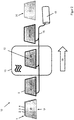
- Figure 2 shows a schematic representation of the method according to the invention in a device 10 according to the invention.
- a stacking sequence 1 is produced from, for example, a substrate wafer 2, an intermediate layer 3 and a cover wafer 4.
- the composite pane 30 to be produced from the stacking sequence 1 by lamination is here, for example, a windshield of a passenger car. It goes without saying that the method according to the invention and the device according to the invention can be used for a large number of composite panes in the vehicle, architectural or decorative sector.
- the substrate disk 2 and the cover disk 4 are each approximately trapezoidal and have a slight curvature, as is customary for modern windshields.
- the substrate disk 2 and the cover disk 4 are of the same size and are arranged congruently one above the other.
- the substrate disk 2 and the cover disk 4 have a width of 0.9 m, for example, and a length at the lower edge U, that is to say on the longer base side of the trapezoidal disks, of 1.5 m, for example.
- the edge opposite the lower edge U has a length of 1.2 m, for example.
- the substrate disk 2 is provided, for example, to face the interior of the vehicle in the installed position, whereas the cover disk 4 is intended to face outward with respect to the vehicle interior.
- Substrate disk 2 and cover disk 4 consist, for example, of soda-lime glass.
- the thickness of the substrate wafer 2 is 1.6 mm, for example, and the thickness of the cover wafer 4 is 2.1 mm. It goes without saying that the substrate wafer 2 and cover wafer 4 can also have the same thickness, for example.
- the intermediate layer 3 is a thermoplastic intermediate layer and consists for example of polyvinyl butyral (PVB). For example, it has a thickness of 0.76 mm to 0.86 mm. In this example, the intermediate layer 3 has a water content of 0.40%, for example.
- a vacuum ring 5 is placed around the outer side edges of the stacking sequence 1.
- the vacuum ring 5 (“greensnake”) consists of a vacuum-stable hose which is in the form of a closed ring and has a slot on its inside into which the outer side edge of the stacking sequence 1 is inserted.
- the vacuum ring 5 completely encloses the side edges and the space between the substrate wafer 2 and the cover wafer 4 and seals it off by vacuum technology.
- the vacuum ring 5 is connected to an optional vacuum compensation tank and a vacuum pump via a vacuum hose.
- Vacuum ring 5, vacuum hose, optionally vacuum compensation tank and vacuum pump form a vacuum system 15.
- the vacuum compensation tank has a volume of 1 m 3 , for example.
- the vacuum pump for example, has a delivery capacity of 300 m 3 / h and reaches a maximum final pressure of 0.1 mbar.
- a stack sequence 1 of a substrate wafer 2, an intermediate layer 3 and a cover layer 4 with a mounted vacuum ring 5 is shown under b1).
- the stacking sequence is arranged in an upright position and along the direction of transport 20.
- the stacking sequence 1 is inserted into a transport device, not shown here, which transports the stacking sequence 1 through the device 10 along the transport direction 20.
- the transport device is, for example, a conveyor belt with suitable holders for receiving the stacking sequence 1.
- the vacuum ring 5 and the vacuum hose that connects the vacuum ring 5 to the vacuum pump are designed to be movable so that they can be moved with the stacking sequence 1 while maintaining the Can be transported through the device 10 under vacuum.
- the venting in this process step takes place at a temperature T 1 of the stacking sequence 1 between 0 ° C. and 30 ° C. and, for example, room temperature (RT) of the environment. This takes place over a time period t 1 of greater than or equal to 8 minutes and, for example, of 25 minutes.
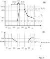
- Figure 3A shows an exemplary diagram of the temperature profile during the method according to the invention.
- the horizontal axis is divided into process steps. Both axes are not to scale.
- Figure 3B shows an exemplary diagram of the pressure profile during the method according to the invention.
- the horizontal axis is divided into process steps. Both axes are not to scale.
- a step b3) the stack sequence 1 is transported by the transport device into the microwaves 12 of the device 10 and heated there.
- the microwave range 12 is generated in the interior of a microwave oven 13 which emits microwave radiation at, for example, 2.45 GHz.
- There the stacking sequence 1 is heated to a temperature T 2 of 70 ° C. to 130 ° C. and, for example, to 95 ° C. within a time period t 2 of, for example, 3 minutes.
- the negative pressure of p 2 0.1 bar on the vacuum ring is continuously maintained. It goes without saying that the negative pressure can also only be applied periodically. This is particularly the case when using a vacuum bag method in which the vacuum bag is decoupled from the vacuum system during transport between several positions.
- a step b4) the stacking sequence 1 is vented at temperature T 3 of, for example, 95 ° C. over a period of time t 3 of greater than or equal to 8 minutes and, for example, of 15 minutes.
- the negative pressure of p 3 0.1 bar on the vacuum ring is continuously maintained.
- the stacking sequence 1 is cooled to a temperature T 4 of less than 70.degree. C., for example to a temperature T 4 of 50.degree.
- the cooling can be accelerated for example by a cooling unit not shown here, for example by an air flow of air from the environment of the device 10 with a fan. Cooling under negative pressure is advantageous, since cooling without negative pressure leads to the formation of bubbles and cloudiness in the later composite pane.
- a step b6 the suction effect on the vacuum ring 5 of the stacking sequence 1 is switched off and an ambient pressure is applied, as a result of which the vacuum ring 5 is ventilated.
- the vacuum ring 5 is then removed from the stacking sequence 1 in a step c).
- the stacking sequence 1 continues to cool during steps b6) and c) until it finally reaches room temperature RT.
- composite panes 30 with excellent quality with regard to transparency, cloudiness or clarity and strength could be produced without autoclaves using the methods illustrated here by way of example.
- the method according to the invention is therefore particularly energy-saving and, thanks to a short process time, is very cost-effective. It goes without saying that, alternatively and in order to achieve special properties, further process steps such as an autoclave process or a calender process can also follow.
- Figure 4 shows a perspective view of an alternative device 10 according to the invention for performing the method according to the invention.
- composite panes 30 with the corresponding process steps of Figure 1 , as well as the Figures 3A and 3B produce, so that in the following only the differences between the devices 10 between Figure 2 and Figure 4 is received.
- a plurality of stacking sequences 1 each consisting of a substrate wafer 2, an intermediate layer 3 and a cover layer 4, each with a mounted vacuum ring 5, are shown.
- the stacking sequences 1 are arranged in an upright position and parallel to one another.
- the stacking sequences 1 are inserted into a transport device, not shown, which transports the stacking sequences 1 through the device along the transport direction 20.
- the stacking sequences 1 are oriented transversely to the transport direction.
- the transport device is, for example, a conveyor belt with suitable holders for receiving the stacking sequences 1.
- the vacuum ring 5 and the vacuum hose that connects the vacuum ring 5 to the vacuum pump are designed to be movable so that they can be moved with the stacking sequence 1 while maintaining the Can be transported through the device 10 under vacuum.
- a cooling unit 14 is shown, which is arranged behind the microwave oven 13.
- the cooling of the stack sequence 1 after passing through the microwave region 12 can be accelerated here, for example, by an air flow of air from the surroundings of the device 10 with a fan.
Landscapes
- Engineering & Computer Science (AREA)
- Mechanical Engineering (AREA)
- General Engineering & Computer Science (AREA)
- Physics & Mathematics (AREA)
- Thermal Sciences (AREA)
- Joining Of Glass To Other Materials (AREA)
- Lining Or Joining Of Plastics Or The Like (AREA)
- Laminated Bodies (AREA)
Priority Applications (1)
| Application Number | Priority Date | Filing Date | Title |
|---|---|---|---|
| PL17798186T PL3544810T3 (pl) | 2016-11-22 | 2017-11-13 | Sposób laminacji szyby kompozytowej |
Applications Claiming Priority (2)
| Application Number | Priority Date | Filing Date | Title |
|---|---|---|---|
| EP16199945 | 2016-11-22 | ||
| PCT/EP2017/079005 WO2018095749A1 (de) | 2016-11-22 | 2017-11-13 | Verfahren zur lamination einer verbundscheibe |
Publications (2)
| Publication Number | Publication Date |
|---|---|
| EP3544810A1 EP3544810A1 (de) | 2019-10-02 |
| EP3544810B1 true EP3544810B1 (de) | 2020-10-21 |
Family
ID=57421636
Family Applications (1)
| Application Number | Title | Priority Date | Filing Date |
|---|---|---|---|
| EP17798186.7A Active EP3544810B1 (de) | 2016-11-22 | 2017-11-13 | Verfahren zur lamination einer verbundscheibe |
Country Status (10)
| Country | Link |
|---|---|
| EP (1) | EP3544810B1 (pl) |
| CN (1) | CN108349220B (pl) |
| BR (1) | BR112019001835A2 (pl) |
| CO (1) | CO2019001971A2 (pl) |
| ES (1) | ES2828605T3 (pl) |
| MX (1) | MX384743B (pl) |
| PL (1) | PL3544810T3 (pl) |
| PT (1) | PT3544810T (pl) |
| RU (1) | RU2715849C1 (pl) |
| WO (1) | WO2018095749A1 (pl) |
Families Citing this family (1)
| Publication number | Priority date | Publication date | Assignee | Title |
|---|---|---|---|---|
| CN115871251A (zh) * | 2022-12-06 | 2023-03-31 | 溧阳二十八所系统装备有限公司 | 真空辅助成型系统及其使用方法 |
Family Cites Families (12)
| Publication number | Priority date | Publication date | Assignee | Title |
|---|---|---|---|---|
| DE2321979A1 (de) * | 1973-05-02 | 1974-11-21 | Heinz Goch | Vorrichtung fuer die herstellung von flaechig miteinander zu verbindenden scheiben |
| GB1590837A (en) * | 1976-11-30 | 1981-06-10 | Bfg Glassgroup | Manufacture of fire screening panels |
| FR2738772B1 (fr) | 1995-09-15 | 1997-10-24 | Saint Gobain Vitrage | Vitrage feuillete d'isolation acoustique |
| DE69715567T3 (de) | 1996-11-26 | 2016-08-04 | Saint-Gobain Glass France S.A. | Verwendung einer Verbundglasscheibe zur Dämmung von durch Festkörper geleiteten Schwingungen in einem Fahrzeug |
| FR2757151B1 (fr) | 1996-12-12 | 1999-01-08 | Saint Gobain Vitrage | Vitrage comprenant un substrat muni d'un empilement de couches minces pour la protection solaire et/ou l'isolation thermique |
| DE19903171C2 (de) * | 1999-01-27 | 2003-03-20 | Saint Gobain Sekurit D Gmbh | Verfahren und Vorrichtung zum Laminieren von Verbundscheiben |
| US20070034317A1 (en) * | 2004-03-17 | 2007-02-15 | Valdislav Sklyarevich | Method and apparatus for laminating glass sheets |
| EP1967805A1 (en) * | 2007-03-09 | 2008-09-10 | Hornos Industriales Pujol S.A. | Vertical glass rolling furnace without vacuum bag |
| US20090126859A1 (en) * | 2007-11-16 | 2009-05-21 | Cadwallader Robert J | Process for producing glass laminates |
| DE202008017611U1 (de) | 2008-12-20 | 2010-04-22 | Saint-Gobain Sekurit Deutschland Gmbh & Co. Kg | Scheibenförmiges, transparentes, elektrisch beheizbares Verbundmaterial |
| EP2444381A1 (de) | 2010-10-19 | 2012-04-25 | Saint-Gobain Glass France | Transparente Scheibe |
| CN104591552A (zh) * | 2015-02-09 | 2015-05-06 | 孙宁 | 一种夹胶玻璃及其制备方法 |
-
2017
- 2017-11-13 CN CN201780002392.7A patent/CN108349220B/zh not_active Expired - Fee Related
- 2017-11-13 BR BR112019001835-2A patent/BR112019001835A2/pt active Search and Examination
- 2017-11-13 EP EP17798186.7A patent/EP3544810B1/de active Active
- 2017-11-13 WO PCT/EP2017/079005 patent/WO2018095749A1/de not_active Ceased
- 2017-11-13 MX MX2019005938A patent/MX384743B/es unknown
- 2017-11-13 ES ES17798186T patent/ES2828605T3/es active Active
- 2017-11-13 PL PL17798186T patent/PL3544810T3/pl unknown
- 2017-11-13 PT PT177981867T patent/PT3544810T/pt unknown
- 2017-11-13 RU RU2019107565A patent/RU2715849C1/ru active
-
2019
- 2019-02-28 CO CONC2019/0001971A patent/CO2019001971A2/es unknown
Non-Patent Citations (1)
| Title |
|---|
| None * |
Also Published As
| Publication number | Publication date |
|---|---|
| WO2018095749A1 (de) | 2018-05-31 |
| ES2828605T3 (es) | 2021-05-27 |
| EP3544810A1 (de) | 2019-10-02 |
| MX384743B (es) | 2025-03-14 |
| PL3544810T3 (pl) | 2021-04-06 |
| BR112019001835A2 (pt) | 2019-05-07 |
| MX2019005938A (es) | 2019-07-10 |
| CN108349220A (zh) | 2018-07-31 |
| RU2715849C1 (ru) | 2020-03-03 |
| CO2019001971A2 (es) | 2019-05-31 |
| PT3544810T (pt) | 2020-12-04 |
| CN108349220B (zh) | 2021-08-24 |
Similar Documents
| Publication | Publication Date | Title |
|---|---|---|
| EP3085199B1 (de) | Beheizbare scheibe mit hochfrequenz-transmission | |
| EP2936925B1 (de) | Scheibe mit elektrischer heizschicht | |
| EP3247558B1 (de) | Verbundscheibe mit kapazitivem schaltbereich | |
| EP2380234B2 (de) | Transparente, flächenhaft ausgeführte antenne, verfahren zu ihrer herstellung und ihre verwendung | |
| EP3233746B1 (de) | Verfahren zur herstellung einer verbundscheibe mit korrosionsgeschützter funktioneller beschichtung | |
| EP2436229B1 (de) | ELEKTRISCH GROßFLÄCHIG BEHEIZBARER, TRANSPARENTER GEGENSTAND, VERFAHREN ZU SEINER HERSTELLUNG UND SEINE VERWENDUNG | |
| EP3189706B1 (de) | Scheibe mit elektrischem heizbereich | |
| EP3390042B1 (de) | Verfahren zur autoklavfreien lamination einer verbundscheibe | |
| EP3365174B1 (de) | Verfahren zur herstellung einer verbundscheibe mit infrarotreflektierender beschichtung auf einer trägerfolie | |
| EP3484705B1 (de) | Verbundscheibe mit einer mehrlagigen verbundschicht und verfahren zu ihrer herstellung | |
| WO2014060203A1 (de) | Scheibe mit hochfrequenz-transmission | |
| EP2936926A1 (de) | Scheibe mit elektrischer heizschicht | |
| EP3034295A1 (de) | Verbundscheibe mit korrosionsgeschützter funktioneller beschichtung | |
| WO2021104887A1 (de) | Verbundscheibe mit in thermoplastischer zwischenschicht eingelagertem funktionselement und entlüftungsstruktur | |
| EP3727845A1 (de) | Verbundscheibenanordnung | |
| WO2017102168A1 (de) | Verfahren zur reparatur von substraten mit elektrisch leitfähiger beschichtung und laserschnittmuster | |
| EP3727844A1 (de) | Verbundscheibe | |
| EP3544810B1 (de) | Verfahren zur lamination einer verbundscheibe | |
| DE202014010748U1 (de) | Verbundscheibe mit korrosionsgeschützter funktioneller Beschichtung | |
| WO2021254977A1 (de) | Verfahren zur autoklavfreien lamination einer verbundscheibe | |
| EP3720703A1 (de) | Heizbarer vakuumring | |
| EP4508255A1 (de) | Verglasung mit kommunikationsfenster für sensoren und kamerasysteme | |
| DE202017006838U1 (de) | Elektrisch beheizbare Fensterscheibe mit einer flächenförmigen, netzartig ausgebildeten, elektrisch leitenden Heizstruktur |
Legal Events
| Date | Code | Title | Description |
|---|---|---|---|
| STAA | Information on the status of an ep patent application or granted ep patent |
Free format text: STATUS: UNKNOWN |
|
| STAA | Information on the status of an ep patent application or granted ep patent |
Free format text: STATUS: THE INTERNATIONAL PUBLICATION HAS BEEN MADE |
|
| PUAI | Public reference made under article 153(3) epc to a published international application that has entered the european phase |
Free format text: ORIGINAL CODE: 0009012 |
|
| STAA | Information on the status of an ep patent application or granted ep patent |
Free format text: STATUS: REQUEST FOR EXAMINATION WAS MADE |
|
| 17P | Request for examination filed |
Effective date: 20190514 |
|
| AK | Designated contracting states |
Kind code of ref document: A1 Designated state(s): AL AT BE BG CH CY CZ DE DK EE ES FI FR GB GR HR HU IE IS IT LI LT LU LV MC MK MT NL NO PL PT RO RS SE SI SK SM TR |
|
| AX | Request for extension of the european patent |
Extension state: BA ME |
|
| DAX | Request for extension of the european patent (deleted) | ||
| RAV | Requested validation state of the european patent: fee paid |
Extension state: MA Effective date: 20190514 |
|
| RAP1 | Party data changed (applicant data changed or rights of an application transferred) |
Owner name: SAINT-GOBAIN GLASS FRANCE |
|
| GRAP | Despatch of communication of intention to grant a patent |
Free format text: ORIGINAL CODE: EPIDOSNIGR1 |
|
| STAA | Information on the status of an ep patent application or granted ep patent |
Free format text: STATUS: GRANT OF PATENT IS INTENDED |
|
| INTG | Intention to grant announced |
Effective date: 20200630 |
|
| GRAS | Grant fee paid |
Free format text: ORIGINAL CODE: EPIDOSNIGR3 |
|
| GRAA | (expected) grant |
Free format text: ORIGINAL CODE: 0009210 |
|
| STAA | Information on the status of an ep patent application or granted ep patent |
Free format text: STATUS: THE PATENT HAS BEEN GRANTED |
|
| AK | Designated contracting states |
Kind code of ref document: B1 Designated state(s): AL AT BE BG CH CY CZ DE DK EE ES FI FR GB GR HR HU IE IS IT LI LT LU LV MC MK MT NL NO PL PT RO RS SE SI SK SM TR |
|
| REG | Reference to a national code |
Ref country code: GB Ref legal event code: FG4D Free format text: NOT ENGLISH |
|
| REG | Reference to a national code |
Ref country code: CH Ref legal event code: EP |
|
| REG | Reference to a national code |
Ref country code: DE Ref legal event code: R096 Ref document number: 502017007878 Country of ref document: DE |
|
| REG | Reference to a national code |
Ref country code: IE Ref legal event code: FG4D Free format text: LANGUAGE OF EP DOCUMENT: GERMAN |
|
| REG | Reference to a national code |
Ref country code: AT Ref legal event code: REF Ref document number: 1325427 Country of ref document: AT Kind code of ref document: T Effective date: 20201115 |
|
| REG | Reference to a national code |
Ref country code: PT Ref legal event code: SC4A Ref document number: 3544810 Country of ref document: PT Date of ref document: 20201204 Kind code of ref document: T Free format text: AVAILABILITY OF NATIONAL TRANSLATION Effective date: 20201125 |
|
| REG | Reference to a national code |
Ref country code: SE Ref legal event code: TRGR |
|
| REG | Reference to a national code |
Ref country code: NL Ref legal event code: MP Effective date: 20201021 |
|
| PG25 | Lapsed in a contracting state [announced via postgrant information from national office to epo] |
Ref country code: FI Free format text: LAPSE BECAUSE OF FAILURE TO SUBMIT A TRANSLATION OF THE DESCRIPTION OR TO PAY THE FEE WITHIN THE PRESCRIBED TIME-LIMIT Effective date: 20201021 Ref country code: RS Free format text: LAPSE BECAUSE OF FAILURE TO SUBMIT A TRANSLATION OF THE DESCRIPTION OR TO PAY THE FEE WITHIN THE PRESCRIBED TIME-LIMIT Effective date: 20201021 Ref country code: GR Free format text: LAPSE BECAUSE OF FAILURE TO SUBMIT A TRANSLATION OF THE DESCRIPTION OR TO PAY THE FEE WITHIN THE PRESCRIBED TIME-LIMIT Effective date: 20210122 Ref country code: NO Free format text: LAPSE BECAUSE OF FAILURE TO SUBMIT A TRANSLATION OF THE DESCRIPTION OR TO PAY THE FEE WITHIN THE PRESCRIBED TIME-LIMIT Effective date: 20210121 |
|
| REG | Reference to a national code |
Ref country code: LT Ref legal event code: MG4D |
|
| REG | Reference to a national code |
Ref country code: ES Ref legal event code: FG2A Ref document number: 2828605 Country of ref document: ES Kind code of ref document: T3 Effective date: 20210527 |
|
| PG25 | Lapsed in a contracting state [announced via postgrant information from national office to epo] |
Ref country code: BG Free format text: LAPSE BECAUSE OF FAILURE TO SUBMIT A TRANSLATION OF THE DESCRIPTION OR TO PAY THE FEE WITHIN THE PRESCRIBED TIME-LIMIT Effective date: 20210121 Ref country code: IS Free format text: LAPSE BECAUSE OF FAILURE TO SUBMIT A TRANSLATION OF THE DESCRIPTION OR TO PAY THE FEE WITHIN THE PRESCRIBED TIME-LIMIT Effective date: 20210221 Ref country code: LV Free format text: LAPSE BECAUSE OF FAILURE TO SUBMIT A TRANSLATION OF THE DESCRIPTION OR TO PAY THE FEE WITHIN THE PRESCRIBED TIME-LIMIT Effective date: 20201021 |
|
| VS25 | Lapsed in a validation state [announced via postgrant information from nat. office to epo] |
Ref country code: MA Free format text: LAPSE BECAUSE OF FAILURE TO SUBMIT A TRANSLATION OF THE DESCRIPTION OR TO PAY THE FEE WITHIN THE PRESCRIBED TIME-LIMIT Effective date: 20201021 |
|
| PG25 | Lapsed in a contracting state [announced via postgrant information from national office to epo] |
Ref country code: HR Free format text: LAPSE BECAUSE OF FAILURE TO SUBMIT A TRANSLATION OF THE DESCRIPTION OR TO PAY THE FEE WITHIN THE PRESCRIBED TIME-LIMIT Effective date: 20201021 Ref country code: NL Free format text: LAPSE BECAUSE OF FAILURE TO SUBMIT A TRANSLATION OF THE DESCRIPTION OR TO PAY THE FEE WITHIN THE PRESCRIBED TIME-LIMIT Effective date: 20201021 |
|
| REG | Reference to a national code |
Ref country code: CH Ref legal event code: PL |
|
| REG | Reference to a national code |
Ref country code: DE Ref legal event code: R097 Ref document number: 502017007878 Country of ref document: DE |
|
| PG25 | Lapsed in a contracting state [announced via postgrant information from national office to epo] |
Ref country code: MC Free format text: LAPSE BECAUSE OF FAILURE TO SUBMIT A TRANSLATION OF THE DESCRIPTION OR TO PAY THE FEE WITHIN THE PRESCRIBED TIME-LIMIT Effective date: 20201021 Ref country code: LU Free format text: LAPSE BECAUSE OF NON-PAYMENT OF DUE FEES Effective date: 20201113 Ref country code: LT Free format text: LAPSE BECAUSE OF FAILURE TO SUBMIT A TRANSLATION OF THE DESCRIPTION OR TO PAY THE FEE WITHIN THE PRESCRIBED TIME-LIMIT Effective date: 20201021 Ref country code: EE Free format text: LAPSE BECAUSE OF FAILURE TO SUBMIT A TRANSLATION OF THE DESCRIPTION OR TO PAY THE FEE WITHIN THE PRESCRIBED TIME-LIMIT Effective date: 20201021 Ref country code: SM Free format text: LAPSE BECAUSE OF FAILURE TO SUBMIT A TRANSLATION OF THE DESCRIPTION OR TO PAY THE FEE WITHIN THE PRESCRIBED TIME-LIMIT Effective date: 20201021 Ref country code: RO Free format text: LAPSE BECAUSE OF FAILURE TO SUBMIT A TRANSLATION OF THE DESCRIPTION OR TO PAY THE FEE WITHIN THE PRESCRIBED TIME-LIMIT Effective date: 20201021 Ref country code: SK Free format text: LAPSE BECAUSE OF FAILURE TO SUBMIT A TRANSLATION OF THE DESCRIPTION OR TO PAY THE FEE WITHIN THE PRESCRIBED TIME-LIMIT Effective date: 20201021 |
|
| REG | Reference to a national code |
Ref country code: BE Ref legal event code: MM Effective date: 20201130 |
|
| PLBE | No opposition filed within time limit |
Free format text: ORIGINAL CODE: 0009261 |
|
| STAA | Information on the status of an ep patent application or granted ep patent |
Free format text: STATUS: NO OPPOSITION FILED WITHIN TIME LIMIT |
|
| PG25 | Lapsed in a contracting state [announced via postgrant information from national office to epo] |
Ref country code: DK Free format text: LAPSE BECAUSE OF FAILURE TO SUBMIT A TRANSLATION OF THE DESCRIPTION OR TO PAY THE FEE WITHIN THE PRESCRIBED TIME-LIMIT Effective date: 20201021 Ref country code: LI Free format text: LAPSE BECAUSE OF NON-PAYMENT OF DUE FEES Effective date: 20201130 Ref country code: CH Free format text: LAPSE BECAUSE OF NON-PAYMENT OF DUE FEES Effective date: 20201130 |
|
| 26N | No opposition filed |
Effective date: 20210722 |
|
| PG25 | Lapsed in a contracting state [announced via postgrant information from national office to epo] |
Ref country code: IE Free format text: LAPSE BECAUSE OF NON-PAYMENT OF DUE FEES Effective date: 20201113 Ref country code: AL Free format text: LAPSE BECAUSE OF FAILURE TO SUBMIT A TRANSLATION OF THE DESCRIPTION OR TO PAY THE FEE WITHIN THE PRESCRIBED TIME-LIMIT Effective date: 20201021 |
|
| PG25 | Lapsed in a contracting state [announced via postgrant information from national office to epo] |
Ref country code: SI Free format text: LAPSE BECAUSE OF FAILURE TO SUBMIT A TRANSLATION OF THE DESCRIPTION OR TO PAY THE FEE WITHIN THE PRESCRIBED TIME-LIMIT Effective date: 20201021 |
|
| PGFP | Annual fee paid to national office [announced via postgrant information from national office to epo] |
Ref country code: SE Payment date: 20211012 Year of fee payment: 5 Ref country code: PT Payment date: 20211110 Year of fee payment: 5 Ref country code: CZ Payment date: 20211015 Year of fee payment: 5 Ref country code: ES Payment date: 20211207 Year of fee payment: 5 |
|
| PGFP | Annual fee paid to national office [announced via postgrant information from national office to epo] |
Ref country code: IT Payment date: 20211012 Year of fee payment: 5 |
|
| PGFP | Annual fee paid to national office [announced via postgrant information from national office to epo] |
Ref country code: PL Payment date: 20211012 Year of fee payment: 5 |
|
| PG25 | Lapsed in a contracting state [announced via postgrant information from national office to epo] |
Ref country code: IS Free format text: LAPSE BECAUSE OF FAILURE TO SUBMIT A TRANSLATION OF THE DESCRIPTION OR TO PAY THE FEE WITHIN THE PRESCRIBED TIME-LIMIT Effective date: 20210221 Ref country code: TR Free format text: LAPSE BECAUSE OF FAILURE TO SUBMIT A TRANSLATION OF THE DESCRIPTION OR TO PAY THE FEE WITHIN THE PRESCRIBED TIME-LIMIT Effective date: 20201021 Ref country code: MT Free format text: LAPSE BECAUSE OF FAILURE TO SUBMIT A TRANSLATION OF THE DESCRIPTION OR TO PAY THE FEE WITHIN THE PRESCRIBED TIME-LIMIT Effective date: 20201021 Ref country code: CY Free format text: LAPSE BECAUSE OF FAILURE TO SUBMIT A TRANSLATION OF THE DESCRIPTION OR TO PAY THE FEE WITHIN THE PRESCRIBED TIME-LIMIT Effective date: 20201021 |
|
| PG25 | Lapsed in a contracting state [announced via postgrant information from national office to epo] |
Ref country code: MK Free format text: LAPSE BECAUSE OF FAILURE TO SUBMIT A TRANSLATION OF THE DESCRIPTION OR TO PAY THE FEE WITHIN THE PRESCRIBED TIME-LIMIT Effective date: 20201021 |
|
| GBPC | Gb: european patent ceased through non-payment of renewal fee |
Effective date: 20211113 |
|
| PG25 | Lapsed in a contracting state [announced via postgrant information from national office to epo] |
Ref country code: BE Free format text: LAPSE BECAUSE OF NON-PAYMENT OF DUE FEES Effective date: 20201130 |
|
| PG25 | Lapsed in a contracting state [announced via postgrant information from national office to epo] |
Ref country code: GB Free format text: LAPSE BECAUSE OF NON-PAYMENT OF DUE FEES Effective date: 20211113 |
|
| PGFP | Annual fee paid to national office [announced via postgrant information from national office to epo] |
Ref country code: FR Payment date: 20221010 Year of fee payment: 6 |
|
| PGFP | Annual fee paid to national office [announced via postgrant information from national office to epo] |
Ref country code: DE Payment date: 20220621 Year of fee payment: 6 |
|
| REG | Reference to a national code |
Ref country code: SE Ref legal event code: EUG |
|
| PG25 | Lapsed in a contracting state [announced via postgrant information from national office to epo] |
Ref country code: PT Free format text: LAPSE BECAUSE OF NON-PAYMENT OF DUE FEES Effective date: 20230515 Ref country code: CZ Free format text: LAPSE BECAUSE OF NON-PAYMENT OF DUE FEES Effective date: 20221113 |
|
| PG25 | Lapsed in a contracting state [announced via postgrant information from national office to epo] |
Ref country code: SE Free format text: LAPSE BECAUSE OF NON-PAYMENT OF DUE FEES Effective date: 20221114 |
|
| PG25 | Lapsed in a contracting state [announced via postgrant information from national office to epo] |
Ref country code: IT Free format text: LAPSE BECAUSE OF NON-PAYMENT OF DUE FEES Effective date: 20221113 |
|
| REG | Reference to a national code |
Ref country code: ES Ref legal event code: FD2A Effective date: 20231229 |
|
| REG | Reference to a national code |
Ref country code: AT Ref legal event code: MM01 Ref document number: 1325427 Country of ref document: AT Kind code of ref document: T Effective date: 20221113 |
|
| PG25 | Lapsed in a contracting state [announced via postgrant information from national office to epo] |
Ref country code: ES Free format text: LAPSE BECAUSE OF NON-PAYMENT OF DUE FEES Effective date: 20221114 |
|
| PG25 | Lapsed in a contracting state [announced via postgrant information from national office to epo] |
Ref country code: ES Free format text: LAPSE BECAUSE OF NON-PAYMENT OF DUE FEES Effective date: 20221114 Ref country code: AT Free format text: LAPSE BECAUSE OF NON-PAYMENT OF DUE FEES Effective date: 20221113 |
|
| REG | Reference to a national code |
Ref country code: DE Ref legal event code: R082 Ref document number: 502017007878 Country of ref document: DE Representative=s name: OBERMAIR, CHRISTIAN, DR. RER. NAT., DE |
|
| PG25 | Lapsed in a contracting state [announced via postgrant information from national office to epo] |
Ref country code: PL Free format text: LAPSE BECAUSE OF NON-PAYMENT OF DUE FEES Effective date: 20221113 |
|
| REG | Reference to a national code |
Ref country code: DE Ref legal event code: R119 Ref document number: 502017007878 Country of ref document: DE |
|
| PG25 | Lapsed in a contracting state [announced via postgrant information from national office to epo] |
Ref country code: DE Free format text: LAPSE BECAUSE OF NON-PAYMENT OF DUE FEES Effective date: 20240601 |
|
| PG25 | Lapsed in a contracting state [announced via postgrant information from national office to epo] |
Ref country code: FR Free format text: LAPSE BECAUSE OF NON-PAYMENT OF DUE FEES Effective date: 20231130 |
|
| PG25 | Lapsed in a contracting state [announced via postgrant information from national office to epo] |
Ref country code: FR Free format text: LAPSE BECAUSE OF NON-PAYMENT OF DUE FEES Effective date: 20231130 Ref country code: DE Free format text: LAPSE BECAUSE OF NON-PAYMENT OF DUE FEES Effective date: 20240601 |