EP3544406B1 - Verschlussanordnung für eine rasenverteileranordnung - Google Patents
Verschlussanordnung für eine rasenverteileranordnung Download PDFInfo
- Publication number
- EP3544406B1 EP3544406B1 EP17720428.6A EP17720428A EP3544406B1 EP 3544406 B1 EP3544406 B1 EP 3544406B1 EP 17720428 A EP17720428 A EP 17720428A EP 3544406 B1 EP3544406 B1 EP 3544406B1
- Authority
- EP
- European Patent Office
- Prior art keywords
- hopper
- shutter assembly
- assembly
- spreader
- shutter
- Prior art date
- Legal status (The legal status is an assumption and is not a legal conclusion. Google has not performed a legal analysis and makes no representation as to the accuracy of the status listed.)
- Active
Links
Images


Classifications
-
- A—HUMAN NECESSITIES
- A01—AGRICULTURE; FORESTRY; ANIMAL HUSBANDRY; HUNTING; TRAPPING; FISHING
- A01C—PLANTING; SOWING; FERTILISING
- A01C7/00—Sowing
- A01C7/02—Hand sowing implements
-
- A—HUMAN NECESSITIES
- A01—AGRICULTURE; FORESTRY; ANIMAL HUSBANDRY; HUNTING; TRAPPING; FISHING
- A01C—PLANTING; SOWING; FERTILISING
- A01C15/00—Fertiliser distributors
- A01C15/02—Fertiliser distributors for hand use
Definitions
- the present invention relates to spreader assemblies, and more particularly to a shutter assembly for a lawn spreader assembly.
- Spreader devices are generally used for spreading and distributing materials, including, but not limited to, fertilizer and seeds on surface like, lawn, farm land etc.
- the spreader device typically includes a roller disposed inside a container carrying the material, a feed opening provided in the container for distributing material onto the surface and a shutter device at a bottom portion of the feed opening.
- the shutter device is operated manually by an operator for controlling operation of opening and closing of the feed opening.
- the roller of the spreader device is connected to wheels of the spreader device and rotates with the rotation of the wheels. Further, the roller selectively allows the material to reach a passage leading to the feed opening.
- the passage is defined between a container inner wall and peripheral edges of the roller.
- the spreader device may be employed for spreading material having particles with varying sizes and hardness, the particles often get stuck at the passage, and between the shutter device and the feed opening. This may cause restrict flow of material through the feed opening. Further, the material also often gets damaged when the material gets jammed in between the shutter device and the feed opening. Such jamming of the material between the feed opening and the shutter device is undesired as it may lead to less flow or over flow of material to the surface.
- the U.S. Patent 2,835,420 discloses a shutter bar for fertilizer spreader.
- the fertilizer spreader includes a hopper of generally trough shape in vertical section, the bottom of which is rounded to accommodate the rotating agitators operating in close proximity thereto.
- Agitators are mounted on and spaced along shafts and supported within hopper on an inboard bearing and outboard bearings. Shaft extends through bearing and is secured to a wheel by which the spreader may be rolled over the ground.
- the British publication document GB 3 175 482 A shows a convetional spreader comprising a handle extending upwardly from the hopper.
- a stopper is cooperating with the shutter assembly. Thereby the stopper actuating mechanism is adapted to selectively move the shutter assembly on the hopper.
- the spreader assembly includes a hopper adapted to contain a material.
- the hopper includes a feed opening for selectively discharging the material.
- the spreader assembly further includes a pair of wheels connected to the hopper.
- the spreader assembly further includes a roller rotatably connected to the pair of wheels.
- the spreader assembly further includes a shutter assembly movably disposed on the hopper.
- the shutter assembly includes a body portion having at least one longitudinal recess, and a resilient member disposed at the longitudinal recess of the body portion, the resilient member adapted to selectively slide on the hopper to close the feed opening.
- the resilient member is fixedly connected at the longitudinal recess of the body portion.
- the resilient member includes one or more fins composed of a resilient material.
- the one or more fins define a plurality of grooves in one of a "V" shape and a "U” shape.
- the shutter assembly is manufactured by a multi-component molding process.
- the shutter assembly is manufactured by two component molding process.
- the spreader assembly includes a handle extending upwardly from the hopper.
- the spreader assembly further includes a stopper actuating mechanism disposed on the handle and in connection with the shutter assembly.
- the stopper actuating mechanism is adapted to selectively move the shutter assembly on the hopper.
- the shutter assembly for a spreader assembly includes a hopper adapted to contain a material.
- the hopper includes a feed opening for selectively discharging the material.
- the spreader assembly further includes a pair of wheels connected to the hopper.
- the spreader assembly further includes a roller rotatably connected to the pair of wheels.
- the spreader assembly further includes a shutter assembly movably disposed on the hopper.
- the shutter assembly includes a body portion having at least one longitudinal recess and a resilient member disposed at the longitudinal recess of the body portion. The resilient member is adapted to selectively slide on the hopper to close the feed opening.
- the resilient member of the shutter assembly comes in contact with the of material or particles, and the resilient member includes one or more fins composed of a resilient material, any likelihood of damage thereto from the shutter assembly is reduced.
- the shutter assembly disclosed in the present invention is free from trickling effect after closing the feed opening of the hopper of the spreader assembly.
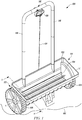
- FIG. 1 illustrates a perspective view of a spreader assembly 100, according to an embodiment of the present invention.
- the spreader assembly 100 may be a farm or a garden implement used for spreading and distributing a material or mixture of materials.
- the material for spreading and distributing may include, but not limited to, fertilizer, seeds, sand, chemical, pesticide and ice melt.
- the material may be in a granular form or pellet form, having predetermined sizes.
- the spreader assembly 100 includes a hopper 102 adapted to contain the material or mixture of materials (not shown).
- the hopper 102 is provided in a cup shape or cylindrical shape or any other shape known in the art, to carry the material during operation of the spreader assembly 100.
- the hopper 102 is further adapted to accommodate at least one roller 104 inside the hopper 102.
- the hopper 102 includes one roller 104.
- the hopper 102 can be adapted to accommodate more than one roller 104, based on design and functional requirements of the spreader assembly 100. It is to be understood that the number of roller 104 described in the present invention is not meant to be limiting the scope of the present invention.
- the hopper 102 may be adapted to accommodate more than one roller 104 for carrying out the spreading and distributing operations on a surface 106.
- the roller 104 may be arranged within the hopper 102, about an axis X-X'.
- the roller 104 is rotatable along with the rotation of a pair of wheels 108, since the pair of wheels 108 is connected to the roller 104 through a shaft 110 (shown in FIG. 2 ) for transferring rotational energy from the pair of wheels 108 to the roller 104.
- the pair of wheels 108 is arranged outside a first side surface 112 and a second side surface 114 opposite to the first side surface 112 of the hopper 102.
- the hopper 102 is further provided with a handle 116 extending upwardly and vertically from the hopper 102.
- the handle 116 facilitates in holding and operating the spreader assembly 100.
- the handle 116 may be a tubular member connected to the hopper 102.
- the tubular member may be, but not limited to, a telescopic tube, a cylindrical tube.
- the handle 116 includes a holding portion 118 and a stopper actuating mechanism 120 connected to the holding portion 118 for controlling operations of a shutter assembly 122 (shown in FIG. 2 ).
- the stopper actuating mechanism 120 is connected to the shutter assembly 122 through a control cable 124.
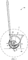
- FIG. 2 illustrates a sectional view of the spreader assembly 100 shown in the FIG. 1 along an axis A-A' according to an embodiment of the present invention.
- the hopper 102 includes the first side surface 112 (shown in FIG. 1 ) and the second side surface 114 (shown in FIG. 1 ) opposite to the first side surface 112, a bottom surface 126 and an open top surface 128 for receiving the material.
- the bottom surface 126 of the hopper 102 is provided with a feed opening 130 along length of the hopper 102.
- the feed opening 130 is adapted to selectively discharge the material from the hopper 102 to the surface 106 by controlling rotation of the roller 104 in the hopper 102.
- the shutter assembly 122 is movably disposed on the hopper 102. Specifically, the shutter assembly 122 is movably disposed on the bottom surface 126 of the hopper 102.
- the stopper actuating mechanism 120 (shown in FIG. 1 ) is connected to the shutter assembly 122 through the control cable 124 at a first end 132 of the shutter assembly 122. Further, a second end 134 of the shutter assembly 122 is detachably connected to a coil spring 136. The coil spring 136 can be fixedly connected to a first end 138 of the bottom surface 126 of the hopper 102.
- the stopper actuating mechanism 120 is operated for activating sliding movement of the shutter assembly 122 on an outer surface 140 of the bottom surface 126 of the hopper 102. The sliding movement of the shutter assembly 122 enables the feed opening 130 to be selectively opened or closed.
- the shutter assembly 122 is slidingly moved on the outer surface 140 of the bottom surface 126 surpassing the feed opening 130, to close the feed opening 130.
- the feed opening 130 may be closed and opened by the shutter assembly 122.
- the feed opening 130 needs to be closed by the shutter assembly 122 and secondly, the spreader assembly 100 needs to be stopped from movement.
- the roller 104 in the hopper 102 is stopped from rotation.
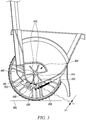
- FIG. 3 illustrates a magnified view of a portion "A" shown in FIG. 2 , according to an embodiment of the present invention.
- the roller 104 includes a plurality of fins 142 and an elongated tubular member 144.
- the shaft 110 is disposed through a hole 146 of the elongated tubular member 144 of the roller 104 for coupling the roller 104 with the pair of wheels 108.
- the roller 104 may be connected to the pair of wheels 108 using any other means know in the art, such as, but not limited to geared connection, splined connection and so on.
- the roller 104 and the pair of wheels 108 form a unitary assembly by an arrangement of the shaft 110 with the roller 104 and the pair of wheels 108.
- a rotation of the pair of wheels 108 on the surface 106 while moving of the spreader assembly 100 drives the roller 104 to rotate in a direction of rotation of the pair of wheels 108.
- the rotation of the roller 104 rotates the elongated tubular member 144, and thus the plurality of fins 142 may be rotated for transferring the material from the hopper 102 to a passage 148.
- an inner surface 150 of the hopper 102 and free ends 152 of each fin of the plurality of fins 142 define the passage 148.
- the passage 148 extends up to the feed opening 130.
- the feed opening 130 allows transfer of the material from the hopper 102 through the passage 148 to the surface 106.
- the passage 148 defined between the inner surface 150 of the hopper 102 and the free ends 152 of each fin of the plurality of fins 142 has a predefined distance " D1 ".
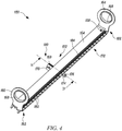
- FIG. 4 illustrates a perspective view of the shutter assembly 122 shown in FIGS. 2 and 3 , according to an embodiment of the present invention.
- the shutter assembly 122 includes a body portion 154 having at least one longitudinal recess 156 (shown in FIGS. 5 and 6 ) along an axis of the body portion 154.
- the longitudinal recess 156 is an elongated groove provided on the body portion 154 at a top end 158 facing the outer surface 140 of the bottom surface 126 of the hopper 102.
- the longitudinal groove can be formed on the body portion 154 using a process, including, but not limited to, milling, machining, and casting or molding.
- the body portion 154 may include multiple longitudinal recesses, such as the longitudinal recess 156 along the axis of the body portion 154.
- the body portion 154 of the shutter assembly 122 further includes a first hinge 160 at a first end 162 and a second hinge 164 at a second end 166 distal to the first end 162.
- Each of the first hinge 160 and the second hinge 164 include a circular profile 168 for connecting with the bottom surface 126 of the hopper 102.
- the first hinge 160 and the second hinge 164 can be in an arcuate shape for facilitating movement of the shutter assembly 122 along the outer surface 140 of the bottom surface 126 of the hopper 102.
- first hinge 160 and the second hinge 164 can be removably connected to the first end 162 and the second end 166.
- the first hinge 160 and the second hinge 164 can be integral parts of the body portion 154 of the shutter assembly 122.
- each of the first hinge 160 and the second hinge 164 may include a bearing (not shown).
- the body portion 154 further includes a first flange portion 169 having a first through hole 170 for connecting with the control cable 124 at a rear end 172.
- the body portion 154 furthermore includes a second flange portion 174 having a second through hole 176 for connecting the body portion 154 of the shutter assembly 122 with the coil spring 136 at the front end 178 of the shutter assembly 122.
- the coil spring 136 may be provided at the rear end 172 of the shutter assembly 122.
- the coil spring 136 may be adapted to apply a resilient force against a movement of the shutter assembly 122.
- the first flange portion 169 and the second flange portion 174 are arranged at a middle portion 180 of the shutter assembly 122.
- the first flange portion 169 and the second flange portion 174 may be provided at any distance along the length of the body portion 154 of the shutter assembly 122 and is not meant to be limiting the scope of the present invention.
- the shutter assembly 122 further includes a plurality of ribs 182 arranged between the second flange portion 174 and the longitudinal recess 156.
- the plurality of ribs 182 may be configured to rigid members.
- the shutter assembly 122 further includes a resilient member 184 disposed at the longitudinal recess 156 of the body portion 154.
- the shutter assembly 122 may include multiple resilient members (not shown), such as the resilient member 184,, disposed at multiple longitudinal recesses of the body portion 154.
- FIG. 5 illustrates a sectional view of the shutter assembly 122 along an axis B-B' shown in FIG. 4 according to an embodiment of the present invention.
- the resilient member 184 of the shutter assembly 122 is arranged at the longitudinal recess 156 of the shutter assembly 122.
- the resilient member 184 is fixedly arranged at the longitudinal recess 156 using a suitable method.
- the resilient member 184 may be fixed at the longitudinal recess 156 using a suitable means including, but not limited to, adhesive.
- the shutter assembly 122 is manufactured by a multi-component molding process.
- the multi-component molding process may include two component molding process.
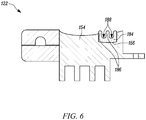
- FIG. 6 illustrates a side view of the shutter assembly 122 shown in FIG. 5 , according to an embodiment of the present invention.
- the resilient member 184 is fixedly connected at the longitudinal recess 156 of the body portion 154.
- the resilient member 184 includes one or more fins 186 composed of a resilient material.
- the fins 186 are adapted to be in a circular ends and forms grooves 188 between any two adjacent fins. In the illustrated embodiment, the grooves 188 are in a "U" shape. However, the fins 186 may include the grooves 188 in other shape like, "V".
- FIG. 7 illustrates a magnified view of a portion of the spreader assembly 100 and the shutter assembly 122, in a first position of the shutter assembly 122.
- the shutter assembly 122 is adapted to close the feed opening 130 in the first position.
- the shutter assembly 122 is in the first position.
- the operator operates the stopper actuating mechanism 120.
- the control cable 124 connected to the stopper actuating mechanism 120 is released and the coil spring 136 connected to the shutter assembly 122 pulls the shutter assembly 122.
- the resilient member 184 Due to such pulling of the shutter assembly 122, the resilient member 184, along with the shutter assembly 122, selectively slides on the hopper 102 for closing the feed opening 130 and thus, locating the shutter assembly 122 at the first position thereof.
- the bottom surface 126 of the hopper 102 may be provided with a stopper (not shown) for restraining further movement of the shutter assembly 122 on the outer surface 140 of the bottom surface 126.
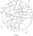
- the operator operates the shutter assembly 122 for closing, and if a particle(s) 190 of the material passing through the feed opening 130 is stuck, then the shutter assembly 122 having the resilient member 184 overrides the particle 190 stuck at the feed opening 130 and thus closes the feed opening 130.
- FIG. 8 illustrates a magnified view of a portion of the spreader assembly 100 and the shutter assembly 122, in a second position of the shutter assembly 122.
- the feed opening 130 of the hopper 102 is opened for allowing the particles 190 of the material from the hopper 102 to the surface 106.
- the shutter assembly 122 may be moved from the first position to the second position.
- the shutter assembly 122 is moved by actuating the stopper actuating mechanism 120 for pulling the control cable 124.
- the shutter assembly 122 is positioned at the second position, for example, during spreading and distributing of the material from the hopper 102 to the surface 106.
- the resilient member 184 of the shutter assembly 122 eliminates chances of material or particles 190 getting stuck between the shutter assembly 122 and the hopper 102. Further, since the resilient member 184 of the shutter assembly 122 comes in contact with the of material or particles 190, and the resilient member 184 includes one or more fins 186 composed of a resilient material, any likelihood of damage thereto from the shutter assembly 122 is reduced.
- the shutter assembly 122 disclosed in the present invention is free from trickling effect after closing the feed opening 130 of the hopper 102 of the spreader assembly 100.
Landscapes
- Life Sciences & Earth Sciences (AREA)
- Soil Sciences (AREA)
- Environmental Sciences (AREA)
- Fertilizing (AREA)
- Catching Or Destruction (AREA)
- Sowing (AREA)
Claims (6)
- Verschlussanordnung (122) für Rasen oder Ackerland für eine Verteileranordnung, umfassend:
einen Aufnahmebehälter (102) zur Aufnahme von Material, wobei der Aufnahmebehälter eine Abgabeöffnung (130) zur gezielten Abgabe des Materials umfasst, ein Paar mit dem Aufnahmebehälter verbundene Räder (108); einen Rollenkörper (104), der drehbar mit dem Räderpaar (108) verbunden ist, wobei die Verschlussanordnung beweglich auf dem Aufnahmebehälter angeordnet ist, wobei die Verschlussanordnung umfasst:einen Körperabschnitt (154) mit mindestens einer Längsausnehmung (156), und einem elastisches Element (184), das an der Längsausnehmung (156) des Körperabschnitts (154) angeordnet ist, wobei das elastische Element (184) ausgelegt ist, um gezielt auf dem Aufnahmebehälter (102) verschoben zu werden, um die Abgabeöffnung (130) zu schließen,dadurch gekennzeichnet, dassdas elastische Element (184) mehrere Rippen (186) umfasst, die aus einem elastischen Material bestehen,wobei die mehreren Rippen (186) eine Vielzahl von Rillen 188 definieren, welche eine "V"- oder eine "U"-Form aufweisen. - Verschlussanordnung (122) für Rasen oder Ackerland nach Anspruch 1, wobei das elastische Element (184) an der Längsausnehmung (156) des Körperabschnitts (154) fest angebracht ist.
- Verschlussanordnung (122) für Rasen oder Ackerland nach Anspruch 1, wobei die Verschlussanordnung (122) durch ein Mehrkomponenten-Formverfahren hergestellt ist.
- Verschlussanordnung (122) für Rasen oder Ackerland nach Anspruch 3, wobei die Verschlussanordnung (122) durch ein Zweikomponenten-Formverfahren hergestellt ist.
- Verteileranordnung (100) für Rasen- oder Ackerland umfassend eine Verschlussanordnung (122) für Rasen oder Ackerland nach einem der Ansprüche 1 bis 4,
ferner umfassend
einen Aufnahmebehälter (102) zur Aufnahme eines Materials, wobei der Aufnahmebehälter (102) eine Abgabeöffnung (130) zur gezielten Abgabe des Materials umfasst;
ein mit dem Aufnahmebehälter verbundenes Räderpaar (108);
einen Rollenkörper (104), der drehbar mit dem Räderpaar (108) verbunden ist; wobei die Verschlussanordnung (122) beweglich auf dem Aufnahmebehälter (102) angeordnet ist. - Verteileranordnung (100) für Rasen- oder Ackerland nach Anspruch 5, ferner umfassend:einen Griff (116), der sich vom Aufnahmebehälter (102) nach oben erstreckt; undeinen Stopper-Betätigungsmechanismus (120), der an dem Griff (116) angeordnet ist und in Verbindung mit der Verschlussanordnung (122) steht, wobei der Stopper-Betätigungsmechanismus (120) dazu ausgelegt ist, die Verschlussanordnung (122) auf dem Aufnahmebehälter (102) gezielt zu bewegen.
Applications Claiming Priority (2)
| Application Number | Priority Date | Filing Date | Title |
|---|---|---|---|
| DE102016013942 | 2016-11-23 | ||
| PCT/EP2017/059660 WO2018095585A1 (en) | 2016-11-23 | 2017-04-24 | Shutter assembly for lawn spreader assembly |
Publications (2)
| Publication Number | Publication Date |
|---|---|
| EP3544406A1 EP3544406A1 (de) | 2019-10-02 |
| EP3544406B1 true EP3544406B1 (de) | 2020-10-21 |
Family
ID=58645040
Family Applications (1)
| Application Number | Title | Priority Date | Filing Date |
|---|---|---|---|
| EP17720428.6A Active EP3544406B1 (de) | 2016-11-23 | 2017-04-24 | Verschlussanordnung für eine rasenverteileranordnung |
Country Status (4)
| Country | Link |
|---|---|
| EP (1) | EP3544406B1 (de) |
| CN (1) | CN109862776B (de) |
| TW (1) | TWI738817B (de) |
| WO (1) | WO2018095585A1 (de) |
Families Citing this family (1)
| Publication number | Priority date | Publication date | Assignee | Title |
|---|---|---|---|---|
| CN112088696A (zh) * | 2020-09-28 | 2020-12-18 | 湖南洪盛源油茶科技股份有限公司 | 一种用于沙土土质地区的油茶树育苗装置 |
Family Cites Families (13)
| Publication number | Priority date | Publication date | Assignee | Title |
|---|---|---|---|---|
| US2835420A (en) | 1955-02-17 | 1958-05-20 | Russell W Foley | Shutter bar for fertilizer spreader |
| GB848718A (en) * | 1958-05-29 | 1960-09-21 | Thomas Cowley & Sons Ltd | An improved distributor for agricultural or horticultural use |
| YU32831B (en) * | 1969-03-21 | 1975-08-31 | Amazonen Werke Dreyer H | Masina za rasturanje materijala u obliku zrna, praha ili tecnosti, narocito mineralnog dubriva |
| DE2605512C2 (de) * | 1976-02-12 | 1986-06-05 | Blohm + Voss Ag, 2000 Hamburg | Zwischen zwei Teilen, insbesondere zwischen dem Lukendeckel und dem Lukensüll eines Schiffes, angeordnetes Dichtungsprofil |
| GB8508399D0 (en) * | 1985-03-30 | 1985-05-09 | L & T Plastics Ltd | Spreader apparatus |
| US5570814A (en) * | 1994-12-16 | 1996-11-05 | Republic Tool & Mfg. Corp. | Collapsible broadcast spreader |
| CN2336556Y (zh) * | 1998-04-28 | 1999-09-08 | 孙全平 | 施肥器 |
| CN100334937C (zh) * | 2004-06-03 | 2007-09-05 | 河北农业大学 | 玉米小麦两用圆管式气吸排种装置 |
| DE102009044237A1 (de) * | 2009-10-13 | 2011-04-28 | Amazonen-Werke H. Dreyer Gmbh & Co. Kg | Schleuderstreuer |
| CN102440104B (zh) * | 2011-09-26 | 2013-06-26 | 中国农业大学 | 摩擦静电吸附式排种器 |
| CN103518442A (zh) * | 2012-07-03 | 2014-01-22 | 陈德伦 | 微型多功能播种施肥机 |
| CN203633140U (zh) * | 2013-12-06 | 2014-06-11 | 广西壮族自治区水力机械研究所 | 肥料定点投放装置、肥料和种子定点投放装置 |
| EP3082392B1 (de) * | 2013-12-17 | 2017-11-22 | Husqvarna AB | Einstellmechanismus für unterschiedliche öffnungsgrade von löchern in einer verteilmaschine |
-
2017
- 2017-04-24 EP EP17720428.6A patent/EP3544406B1/de active Active
- 2017-04-24 WO PCT/EP2017/059660 patent/WO2018095585A1/en not_active Ceased
- 2017-04-24 CN CN201780064012.2A patent/CN109862776B/zh active Active
- 2017-07-06 TW TW106122744A patent/TWI738817B/zh not_active IP Right Cessation
Also Published As
| Publication number | Publication date |
|---|---|
| EP3544406A1 (de) | 2019-10-02 |
| TW201818816A (zh) | 2018-06-01 |
| CN109862776B (zh) | 2021-08-24 |
| TWI738817B (zh) | 2021-09-11 |
| WO2018095585A1 (en) | 2018-05-31 |
| CN109862776A (zh) | 2019-06-07 |
Similar Documents
| Publication | Publication Date | Title |
|---|---|---|
| RU2530994C2 (ru) | Система объемного дозирования с секционной заслонкой | |
| US9657451B2 (en) | Manually operable push from behind spreader | |
| EP3544406B1 (de) | Verschlussanordnung für eine rasenverteileranordnung | |
| EP3840562A1 (de) | Dosiereinheit für pulver- oder partikelförmiges verteilgut und verteilmaschine mit einer solchen dosiereinheit | |
| EP0088480B1 (de) | Vorrichtung zum Streuen von körnigem und/oder pulverigem Material | |
| US10088059B2 (en) | Spreader with rotary slide gate | |
| EP2576913B1 (de) | Tragbare streuvorrichtung zum ausbringen körniger stoffe | |
| US6293438B1 (en) | Methods and apparatus for metering material | |
| US10736263B2 (en) | Controlled-release spreader | |
| EP3793340B1 (de) | Setzlingspflanzwerkzeug und düngerspender | |
| EP3544407B1 (de) | Walze für verteilungsanordnung | |
| EP3836773B1 (de) | Verteilmaschine fuer körniges gut | |
| EP3836775B1 (de) | Dosiereinrichtung für körniges gut | |
| DE102007021442B4 (de) | Schleuderdüngerstreuer mit fernverstellbaren Schleuderscheiben | |
| DE102011002223B3 (de) | Einzelkornausbringeinrichtung | |
| EP3426014B1 (de) | Verteilmaschine | |
| US310228A (en) | John l | |
| KR200343107Y1 (ko) | 점파식 파종기의 흙제거장치 | |
| DE1962150B2 (de) | Pneumatische Einzelkornsävorrichtung | |
| CN219395500U (zh) | 一种用于播撒机的免拆卸舱门结构及播撒机 | |
| EP3232761B1 (de) | Per hebel betätigbare steuerung für unterschiedliche öffnungsgrade von löchern in einem spreizer | |
| US20060151549A1 (en) | Agricultural spreading device | |
| US5988536A (en) | Electro-mechanical dosimeter of seeds and fertilizer | |
| AT219328B (de) | Einrichtung zum Streuen von Dünger oder anderem körnigem Gut | |
| DE626317C (de) | Dibbelmaschine mit um eine senkrechte Achse umlaufendem Zellenkranz |
Legal Events
| Date | Code | Title | Description |
|---|---|---|---|
| STAA | Information on the status of an ep patent application or granted ep patent |
Free format text: STATUS: UNKNOWN |
|
| STAA | Information on the status of an ep patent application or granted ep patent |
Free format text: STATUS: THE INTERNATIONAL PUBLICATION HAS BEEN MADE |
|
| PUAI | Public reference made under article 153(3) epc to a published international application that has entered the european phase |
Free format text: ORIGINAL CODE: 0009012 |
|
| STAA | Information on the status of an ep patent application or granted ep patent |
Free format text: STATUS: REQUEST FOR EXAMINATION WAS MADE |
|
| 17P | Request for examination filed |
Effective date: 20190325 |
|
| AK | Designated contracting states |
Kind code of ref document: A1 Designated state(s): AL AT BE BG CH CY CZ DE DK EE ES FI FR GB GR HR HU IE IS IT LI LT LU LV MC MK MT NL NO PL PT RO RS SE SI SK SM TR |
|
| AX | Request for extension of the european patent |
Extension state: BA ME |
|
| DAV | Request for validation of the european patent (deleted) | ||
| DAX | Request for extension of the european patent (deleted) | ||
| GRAP | Despatch of communication of intention to grant a patent |
Free format text: ORIGINAL CODE: EPIDOSNIGR1 |
|
| STAA | Information on the status of an ep patent application or granted ep patent |
Free format text: STATUS: GRANT OF PATENT IS INTENDED |
|
| INTG | Intention to grant announced |
Effective date: 20200722 |
|
| GRAS | Grant fee paid |
Free format text: ORIGINAL CODE: EPIDOSNIGR3 |
|
| GRAA | (expected) grant |
Free format text: ORIGINAL CODE: 0009210 |
|
| STAA | Information on the status of an ep patent application or granted ep patent |
Free format text: STATUS: THE PATENT HAS BEEN GRANTED |
|
| AK | Designated contracting states |
Kind code of ref document: B1 Designated state(s): AL AT BE BG CH CY CZ DE DK EE ES FI FR GB GR HR HU IE IS IT LI LT LU LV MC MK MT NL NO PL PT RO RS SE SI SK SM TR |
|
| REG | Reference to a national code |
Ref country code: GB Ref legal event code: FG4D |
|
| REG | Reference to a national code |
Ref country code: CH Ref legal event code: EP |
|
| REG | Reference to a national code |
Ref country code: DE Ref legal event code: R096 Ref document number: 602017025839 Country of ref document: DE |
|
| REG | Reference to a national code |
Ref country code: IE Ref legal event code: FG4D |
|
| REG | Reference to a national code |
Ref country code: AT Ref legal event code: REF Ref document number: 1324859 Country of ref document: AT Kind code of ref document: T Effective date: 20201115 |
|
| REG | Reference to a national code |
Ref country code: AT Ref legal event code: MK05 Ref document number: 1324859 Country of ref document: AT Kind code of ref document: T Effective date: 20201021 |
|
| REG | Reference to a national code |
Ref country code: NL Ref legal event code: MP Effective date: 20201021 |
|
| PG25 | Lapsed in a contracting state [announced via postgrant information from national office to epo] |
Ref country code: PT Free format text: LAPSE BECAUSE OF FAILURE TO SUBMIT A TRANSLATION OF THE DESCRIPTION OR TO PAY THE FEE WITHIN THE PRESCRIBED TIME-LIMIT Effective date: 20210222 Ref country code: RS Free format text: LAPSE BECAUSE OF FAILURE TO SUBMIT A TRANSLATION OF THE DESCRIPTION OR TO PAY THE FEE WITHIN THE PRESCRIBED TIME-LIMIT Effective date: 20201021 Ref country code: NO Free format text: LAPSE BECAUSE OF FAILURE TO SUBMIT A TRANSLATION OF THE DESCRIPTION OR TO PAY THE FEE WITHIN THE PRESCRIBED TIME-LIMIT Effective date: 20210121 Ref country code: FI Free format text: LAPSE BECAUSE OF FAILURE TO SUBMIT A TRANSLATION OF THE DESCRIPTION OR TO PAY THE FEE WITHIN THE PRESCRIBED TIME-LIMIT Effective date: 20201021 Ref country code: GR Free format text: LAPSE BECAUSE OF FAILURE TO SUBMIT A TRANSLATION OF THE DESCRIPTION OR TO PAY THE FEE WITHIN THE PRESCRIBED TIME-LIMIT Effective date: 20210122 |
|
| REG | Reference to a national code |
Ref country code: LT Ref legal event code: MG4D |
|
| PG25 | Lapsed in a contracting state [announced via postgrant information from national office to epo] |
Ref country code: ES Free format text: LAPSE BECAUSE OF FAILURE TO SUBMIT A TRANSLATION OF THE DESCRIPTION OR TO PAY THE FEE WITHIN THE PRESCRIBED TIME-LIMIT Effective date: 20201021 Ref country code: AT Free format text: LAPSE BECAUSE OF FAILURE TO SUBMIT A TRANSLATION OF THE DESCRIPTION OR TO PAY THE FEE WITHIN THE PRESCRIBED TIME-LIMIT Effective date: 20201021 Ref country code: PL Free format text: LAPSE BECAUSE OF FAILURE TO SUBMIT A TRANSLATION OF THE DESCRIPTION OR TO PAY THE FEE WITHIN THE PRESCRIBED TIME-LIMIT Effective date: 20201021 Ref country code: LV Free format text: LAPSE BECAUSE OF FAILURE TO SUBMIT A TRANSLATION OF THE DESCRIPTION OR TO PAY THE FEE WITHIN THE PRESCRIBED TIME-LIMIT Effective date: 20201021 Ref country code: IS Free format text: LAPSE BECAUSE OF FAILURE TO SUBMIT A TRANSLATION OF THE DESCRIPTION OR TO PAY THE FEE WITHIN THE PRESCRIBED TIME-LIMIT Effective date: 20210221 Ref country code: BG Free format text: LAPSE BECAUSE OF FAILURE TO SUBMIT A TRANSLATION OF THE DESCRIPTION OR TO PAY THE FEE WITHIN THE PRESCRIBED TIME-LIMIT Effective date: 20210121 Ref country code: SE Free format text: LAPSE BECAUSE OF FAILURE TO SUBMIT A TRANSLATION OF THE DESCRIPTION OR TO PAY THE FEE WITHIN THE PRESCRIBED TIME-LIMIT Effective date: 20201021 |
|
| PG25 | Lapsed in a contracting state [announced via postgrant information from national office to epo] |
Ref country code: HR Free format text: LAPSE BECAUSE OF FAILURE TO SUBMIT A TRANSLATION OF THE DESCRIPTION OR TO PAY THE FEE WITHIN THE PRESCRIBED TIME-LIMIT Effective date: 20201021 Ref country code: NL Free format text: LAPSE BECAUSE OF FAILURE TO SUBMIT A TRANSLATION OF THE DESCRIPTION OR TO PAY THE FEE WITHIN THE PRESCRIBED TIME-LIMIT Effective date: 20201021 |
|
| REG | Reference to a national code |
Ref country code: DE Ref legal event code: R097 Ref document number: 602017025839 Country of ref document: DE |
|
| PG25 | Lapsed in a contracting state [announced via postgrant information from national office to epo] |
Ref country code: SM Free format text: LAPSE BECAUSE OF FAILURE TO SUBMIT A TRANSLATION OF THE DESCRIPTION OR TO PAY THE FEE WITHIN THE PRESCRIBED TIME-LIMIT Effective date: 20201021 Ref country code: LT Free format text: LAPSE BECAUSE OF FAILURE TO SUBMIT A TRANSLATION OF THE DESCRIPTION OR TO PAY THE FEE WITHIN THE PRESCRIBED TIME-LIMIT Effective date: 20201021 Ref country code: EE Free format text: LAPSE BECAUSE OF FAILURE TO SUBMIT A TRANSLATION OF THE DESCRIPTION OR TO PAY THE FEE WITHIN THE PRESCRIBED TIME-LIMIT Effective date: 20201021 Ref country code: CZ Free format text: LAPSE BECAUSE OF FAILURE TO SUBMIT A TRANSLATION OF THE DESCRIPTION OR TO PAY THE FEE WITHIN THE PRESCRIBED TIME-LIMIT Effective date: 20201021 Ref country code: SK Free format text: LAPSE BECAUSE OF FAILURE TO SUBMIT A TRANSLATION OF THE DESCRIPTION OR TO PAY THE FEE WITHIN THE PRESCRIBED TIME-LIMIT Effective date: 20201021 Ref country code: RO Free format text: LAPSE BECAUSE OF FAILURE TO SUBMIT A TRANSLATION OF THE DESCRIPTION OR TO PAY THE FEE WITHIN THE PRESCRIBED TIME-LIMIT Effective date: 20201021 |
|
| PLBE | No opposition filed within time limit |
Free format text: ORIGINAL CODE: 0009261 |
|
| STAA | Information on the status of an ep patent application or granted ep patent |
Free format text: STATUS: NO OPPOSITION FILED WITHIN TIME LIMIT |
|
| PG25 | Lapsed in a contracting state [announced via postgrant information from national office to epo] |
Ref country code: DK Free format text: LAPSE BECAUSE OF FAILURE TO SUBMIT A TRANSLATION OF THE DESCRIPTION OR TO PAY THE FEE WITHIN THE PRESCRIBED TIME-LIMIT Effective date: 20201021 |
|
| 26N | No opposition filed |
Effective date: 20210722 |
|
| PG25 | Lapsed in a contracting state [announced via postgrant information from national office to epo] |
Ref country code: AL Free format text: LAPSE BECAUSE OF FAILURE TO SUBMIT A TRANSLATION OF THE DESCRIPTION OR TO PAY THE FEE WITHIN THE PRESCRIBED TIME-LIMIT Effective date: 20201021 Ref country code: IT Free format text: LAPSE BECAUSE OF FAILURE TO SUBMIT A TRANSLATION OF THE DESCRIPTION OR TO PAY THE FEE WITHIN THE PRESCRIBED TIME-LIMIT Effective date: 20201021 |
|
| PG25 | Lapsed in a contracting state [announced via postgrant information from national office to epo] |
Ref country code: SI Free format text: LAPSE BECAUSE OF FAILURE TO SUBMIT A TRANSLATION OF THE DESCRIPTION OR TO PAY THE FEE WITHIN THE PRESCRIBED TIME-LIMIT Effective date: 20201021 Ref country code: MC Free format text: LAPSE BECAUSE OF FAILURE TO SUBMIT A TRANSLATION OF THE DESCRIPTION OR TO PAY THE FEE WITHIN THE PRESCRIBED TIME-LIMIT Effective date: 20201021 |
|
| GBPC | Gb: european patent ceased through non-payment of renewal fee |
Effective date: 20210424 |
|
| PG25 | Lapsed in a contracting state [announced via postgrant information from national office to epo] |
Ref country code: LU Free format text: LAPSE BECAUSE OF NON-PAYMENT OF DUE FEES Effective date: 20210424 |
|
| REG | Reference to a national code |
Ref country code: BE Ref legal event code: MM Effective date: 20210430 |
|
| PG25 | Lapsed in a contracting state [announced via postgrant information from national office to epo] |
Ref country code: GB Free format text: LAPSE BECAUSE OF NON-PAYMENT OF DUE FEES Effective date: 20210424 Ref country code: LI Free format text: LAPSE BECAUSE OF NON-PAYMENT OF DUE FEES Effective date: 20210430 Ref country code: CH Free format text: LAPSE BECAUSE OF NON-PAYMENT OF DUE FEES Effective date: 20210430 |
|
| PG25 | Lapsed in a contracting state [announced via postgrant information from national office to epo] |
Ref country code: IE Free format text: LAPSE BECAUSE OF NON-PAYMENT OF DUE FEES Effective date: 20210424 |
|
| PG25 | Lapsed in a contracting state [announced via postgrant information from national office to epo] |
Ref country code: IS Free format text: LAPSE BECAUSE OF FAILURE TO SUBMIT A TRANSLATION OF THE DESCRIPTION OR TO PAY THE FEE WITHIN THE PRESCRIBED TIME-LIMIT Effective date: 20210221 |
|
| PGFP | Annual fee paid to national office [announced via postgrant information from national office to epo] |
Ref country code: FR Payment date: 20220309 Year of fee payment: 6 |
|
| PG25 | Lapsed in a contracting state [announced via postgrant information from national office to epo] |
Ref country code: BE Free format text: LAPSE BECAUSE OF NON-PAYMENT OF DUE FEES Effective date: 20210430 |
|
| P01 | Opt-out of the competence of the unified patent court (upc) registered |
Effective date: 20230419 |
|
| PG25 | Lapsed in a contracting state [announced via postgrant information from national office to epo] |
Ref country code: CY Free format text: LAPSE BECAUSE OF FAILURE TO SUBMIT A TRANSLATION OF THE DESCRIPTION OR TO PAY THE FEE WITHIN THE PRESCRIBED TIME-LIMIT Effective date: 20201021 |
|
| PG25 | Lapsed in a contracting state [announced via postgrant information from national office to epo] |
Ref country code: HU Free format text: LAPSE BECAUSE OF FAILURE TO SUBMIT A TRANSLATION OF THE DESCRIPTION OR TO PAY THE FEE WITHIN THE PRESCRIBED TIME-LIMIT; INVALID AB INITIO Effective date: 20170424 |
|
| PG25 | Lapsed in a contracting state [announced via postgrant information from national office to epo] |
Ref country code: FR Free format text: LAPSE BECAUSE OF NON-PAYMENT OF DUE FEES Effective date: 20230430 |
|
| PG25 | Lapsed in a contracting state [announced via postgrant information from national office to epo] |
Ref country code: MK Free format text: LAPSE BECAUSE OF FAILURE TO SUBMIT A TRANSLATION OF THE DESCRIPTION OR TO PAY THE FEE WITHIN THE PRESCRIBED TIME-LIMIT Effective date: 20201021 |
|
| PG25 | Lapsed in a contracting state [announced via postgrant information from national office to epo] |
Ref country code: TR Free format text: LAPSE BECAUSE OF FAILURE TO SUBMIT A TRANSLATION OF THE DESCRIPTION OR TO PAY THE FEE WITHIN THE PRESCRIBED TIME-LIMIT Effective date: 20201021 |
|
| PG25 | Lapsed in a contracting state [announced via postgrant information from national office to epo] |
Ref country code: MT Free format text: LAPSE BECAUSE OF FAILURE TO SUBMIT A TRANSLATION OF THE DESCRIPTION OR TO PAY THE FEE WITHIN THE PRESCRIBED TIME-LIMIT Effective date: 20201021 |
|
| PGFP | Annual fee paid to national office [announced via postgrant information from national office to epo] |
Ref country code: DE Payment date: 20250313 Year of fee payment: 9 |