EP3543068B1 - Kopfstütze - Google Patents
Kopfstütze Download PDFInfo
- Publication number
- EP3543068B1 EP3543068B1 EP19020091.5A EP19020091A EP3543068B1 EP 3543068 B1 EP3543068 B1 EP 3543068B1 EP 19020091 A EP19020091 A EP 19020091A EP 3543068 B1 EP3543068 B1 EP 3543068B1
- Authority
- EP
- European Patent Office
- Prior art keywords
- head
- holding device
- locking means
- contact part
- head rest
- Prior art date
- Legal status (The legal status is an assumption and is not a legal conclusion. Google has not performed a legal analysis and makes no representation as to the accuracy of the status listed.)
- Active
Links
Images



Classifications
-
- B—PERFORMING OPERATIONS; TRANSPORTING
- B60—VEHICLES IN GENERAL
- B60N—SEATS SPECIALLY ADAPTED FOR VEHICLES; VEHICLE PASSENGER ACCOMMODATION NOT OTHERWISE PROVIDED FOR
- B60N2/00—Seats specially adapted for vehicles; Arrangement or mounting of seats in vehicles
- B60N2/80—Head-rests
- B60N2/806—Head-rests movable or adjustable
- B60N2/865—Head-rests movable or adjustable providing a fore-and-aft movement with respect to the occupant's head
-
- B—PERFORMING OPERATIONS; TRANSPORTING
- B60—VEHICLES IN GENERAL
- B60N—SEATS SPECIALLY ADAPTED FOR VEHICLES; VEHICLE PASSENGER ACCOMMODATION NOT OTHERWISE PROVIDED FOR
- B60N2/00—Seats specially adapted for vehicles; Arrangement or mounting of seats in vehicles
- B60N2/80—Head-rests
- B60N2/806—Head-rests movable or adjustable
-
- B—PERFORMING OPERATIONS; TRANSPORTING
- B60—VEHICLES IN GENERAL
- B60N—SEATS SPECIALLY ADAPTED FOR VEHICLES; VEHICLE PASSENGER ACCOMMODATION NOT OTHERWISE PROVIDED FOR
- B60N2/00—Seats specially adapted for vehicles; Arrangement or mounting of seats in vehicles
- B60N2/80—Head-rests
- B60N2/806—Head-rests movable or adjustable
- B60N2/809—Head-rests movable or adjustable vertically slidable
-
- B—PERFORMING OPERATIONS; TRANSPORTING
- B60—VEHICLES IN GENERAL
- B60N—SEATS SPECIALLY ADAPTED FOR VEHICLES; VEHICLE PASSENGER ACCOMMODATION NOT OTHERWISE PROVIDED FOR
- B60N2/00—Seats specially adapted for vehicles; Arrangement or mounting of seats in vehicles
- B60N2/80—Head-rests
- B60N2/806—Head-rests movable or adjustable
- B60N2/838—Tiltable
- B60N2/862—Tiltable with means for maintaining a desired position when the seat-back is adjusted, e.g. parallelogram mechanisms
-
- B—PERFORMING OPERATIONS; TRANSPORTING
- B60—VEHICLES IN GENERAL
- B60N—SEATS SPECIALLY ADAPTED FOR VEHICLES; VEHICLE PASSENGER ACCOMMODATION NOT OTHERWISE PROVIDED FOR
- B60N2/00—Seats specially adapted for vehicles; Arrangement or mounting of seats in vehicles
- B60N2/80—Head-rests
- B60N2/891—Head-rests with the head-rest being comma-shaped in side view
-
- B—PERFORMING OPERATIONS; TRANSPORTING
- B60—VEHICLES IN GENERAL
- B60N—SEATS SPECIALLY ADAPTED FOR VEHICLES; VEHICLE PASSENGER ACCOMMODATION NOT OTHERWISE PROVIDED FOR
- B60N2/00—Seats specially adapted for vehicles; Arrangement or mounting of seats in vehicles
- B60N2/90—Details or parts not otherwise provided for
- B60N2/919—Positioning and locking mechanisms
- B60N2/933—Positioning and locking mechanisms rotatable
- B60N2/943—Stepwise movement mechanisms, e.g. ratchets
Definitions
- the invention relates to a headrest, in particular for a vehicle seat, with four-bar mounting.
- Such a headrest is known from DE 10 2010 007 942 A1 .
- the headrest comprises a holding device with which a head rest can be mounted on a vehicle seat.
- a four-bar linkage is arranged between the head support and the holding device, with which the head support can be moved between a front position and a rear position.
- the head rest can be locked in different positions when moving between the front position and the rear position.
- the links of the four-bar linkage are shaped like a segment of a circle and comprise a toothing at one end area with which a lever pivotably mounted on the holding device can be releasably engaged in a form-fitting manner to lock the head system.
- WO 2017/111310 A1 relates to a headrest with a holding device and a head support part, the head support part being movably supported on the holding device by means of a first pair of links and a second pair of links.
- the headrest part can be locked in different positions by means of a locking device.
- DE 10 2015 206 956 A1 relates to a headrest with a holding device and a headrest part which can be moved between a rear position and a front position.
- the head rest part is mounted on the holding device by means of a first pair of links and a second pair of links, the links forming swivel joints with the holding device and with the head rest part.
- the adjustment takes place by means of an actuator 94, comprising an electric motor 156.
- the headrest is provided for a seat, in particular for a vehicle seat. It is equipped with a head rest and with a holding device for mounting the headrest on a structure of the vehicle.
- the structure of the vehicle can be, for example, a vehicle seat, in particular the backrest of a vehicle seat.
- Holding device can be any structure with which an attachment to the vehicle structure is possible.
- the headrest comprises at least one four-bar link between the head rest and the holding device, by means of which the head rest is mounted so as to be movable relative to the holding device between a first position and a second position.
- the four-bar linkage comprises at least two links, each link forming at least one joint with the holding device and at least one joint with the head system.
- the headrest comprises at least one locking device which is provided with first locking means associated with the holding device and second locking means associated with the head support.
- the first locking means are firmly held on the holding device or, according to an alternative, an upper area of at least one link is provided with the first locking means.
- the second locking means are firmly held on the head system.
- the holding device comprises e.g. at least one support rod or a support rod bracket.
- the support rod does not have to be a rod in the conventional sense, it can e.g. in the sense of the invention also be a sheet metal.
- the holding device can e.g. comprise an approximately U-shaped plate with free end regions. At the end areas are e.g. The four-bar linkage is articulated.
- the sheet is e.g. mounted on at least one support rod or on a support rod bracket, wherein the support rod or the support rod bracket can be mounted on the backrest.
- the sheet can e.g. also be held directly on the backrest.
- the holding device can e.g. can also simply be formed by a base plate which can be fastened to the backrest structure.
- the holding device forms e.g. the first locking means off.
- the head system includes, for example, a holder.
- the holder forms, for example, the joints between the links of the four-bar linkage and the head system.
- the holder is, for example, integrally connected to a head support plate or designed as a separate part. In the latter case, the head support plate can be movable relative to the holder.
- the holder takes, for example, part of the locking device.
- the holding device comprises at least one projection extending over the joints on the head contact side.
- the projection can e.g. be formed by a support rod or a support rod bracket.
- the projection extends e.g. from the holding device approximately vertically.
- the first locking means can be formed adjacent to the second locking means. It does not have to be bridged a long distance between the first locking means and the second locking means in order to move them between the locking position and the release position.
- the first locking means are assigned to the projection.
- the projection forms the first locking means e.g. out.
- the first locking means are formed by a region of the projection or by an element attached to the projection.
- the second locking means comprise e.g. at least one lock that can be displaced between the locking position and the release position.
- the latch can e.g. have the shape of at least one projection which engages in a recess of the first locking means or comprises at least one recess which is positively releasably movable into engagement with a structure of the first locking means.
- the at least one latch is formed, for example, by at least one toothed rail which is provided with at least one recess.
- one of the recesses can then optionally be releasably movable into engagement with the first locking means, for example with one Area of a projection of the holding device which forms the first locking means.
- the toothed splint can be displaced essentially in a substantially horizontal plane between the locking position and the release position in order to move the locking device between the locking position and the release position.
- the first locking means are formed by two projections encompassed on the holding device and the second locking means are formed by two rack rails mounted on the head support.
- the tooth splint is e.g. formed by a locking element.
- the locking element is e.g. translationally displaceable.
- the latches are loaded into the latch position by a spring and can be moved into the release position against the force of the spring.
- the locking device is arranged adjacent to the headrest-side joints of the four-bar linkage. With these features, the lever forces acting on the holding device are reduced.
- the locking device, in particular the second locking means is arranged above the joints of the four-bar joint on the head contact side.
- the headrest has, for example, an adjusting device for vertical adjustment of the entire headrest or part of the headrest.
- the vertical adjustment of the headrest can for example according to the headrest according to DE 10 2017 007 149 A1 be designed, the disclosure of which is fully incorporated into this application.
- a headrest of a vehicle seat as a whole is denoted by the reference numeral 10 in the figures.
- the same reference symbols in the different figures denote corresponding parts, even if small letters are added or omitted.
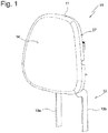
- FIG Fig. 1 A perspective view of the headrest 10 is shown in FIG Fig. 1 shown.
- the headrest 10 comprises a head rest 11 and a holding device 12, which in the present exemplary embodiment comprises two support rods 13a and 13b.
- the head support 11 comprises a head support plate 27 and a holder 18, which in the present case Embodiment is a separate part, but can alternatively also be integrally connected to the head contact plate 27.
- the support rods 13a and 13b are fixedly connected to a rod 37 to form a support rod bracket 38, which is part of the holding device 12, for stabilization.
- the head support 11 has a head support surface 14 which forms an abutment for the head of the seat occupant.
- Lower ends 15a and 15b of the support bars 13a and 13b are e.g. attachable to the backrest structure of a seat (not shown).
- the head rest 11 can be adjusted into different positions by means of an adjustment device 40.
- the adjusting device 40 comprises a four-bar device 23 with two links 16 and 17.
- Each of the links 16 and 17 comprises arms 34a and 34b and a cross member 33 which connects the arms 34a and 34b.
- the traverse 33 essentially serves to improve the stability.
- the cross member 33 as a connection between the arms 34a and 34b could alternatively also be omitted.
- the link 16 forms a joint G1 with the support rod 13b (see FIG Fig. 2 ) and the link 17 forms a joint G2 with the support rod 13b.
- the handlebar 16, in particular the arm 34b of the handlebar 16 also forms a joint G3 with the head system 11, in the present case with a side area 35 of the holder 18 of the headrest 11, while the handlebar 17, in particular the arm 34b of the handlebar 17, forms a joint G4 with the side region 35 of the holder 18.
- the links 16 and 17 each form a joint with the support rod 13a on a side area 36 opposite the side area 35 and also each form a joint with the holder 18, which is shown in FIG Fig. 2 is not recognizable.
- the head system 11 is by means of a four-bar device 23 comprising the support rod bracket 38, the handlebars 16 and 17 and the head system 11 with the holder 18 relative to the holding device 12 between a rear position (see FIGS Figs. 2 to 4 ) and a front position (see Fig. 5 ) displaceable in the directions x1 and x2, the head support 11 executing a curve movement with parts of a movement in the Z direction and parts of a movement in the X direction.
- the adjusting device 40 comprises a locking device 19 with which the head rest 11 can be locked in the rear position or the front position or in a position between the rear position and the front position.
- the locking device 19 comprises first locking means assigned to the head support 11 and second locking means assigned to the support rods 13a and 13b, which can be releasably brought into engagement.
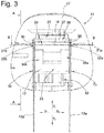
- the support rods 13a and 13b are extended beyond the joints G1 and G2, in particular beyond the joints G3 and G4, in the direction z1 and are provided with the second locking means in the form of a locking area 20.
- the locking area 20 is formed directly by the support rods 13a and 13b.
- the first locking means are designed in the form of two bolts 21a and 21b which are movable relative to the holder 18 and are each provided with a tooth structure 22a and 22b, in this embodiment in the form of a toothed rail. In Fig. 2 only the tooth structure 22b can be seen.
- Fig. 2 it can also be seen that the locking device 19 is in a locking position, ie that the tooth structure 22b is in engagement with the locking area 20, so that the Head rest 11 is not movable between the rear and the front position.
- Fig. 3 the articulated connection between the link 17 and the support rod 13a can be seen in the form of a joint G5.
- a rear region 24 of the holder 18 comprises the tooth structures 22a and 22b, which extend essentially in the x direction.
- a front area 25 is provided with a guide device 26 in order to mount the head support plate 27 movably in directions z1 and z2 between an upper position and a lower position.
- the head support plate 27 can be locked with a locking device in the upper position, the lower position and in intermediate positions between the upper position and the lower position.
- Fig. 4 the head rest 11 is locked in the rear position by means of the locking device 23.
- Fig. 5 shows the head rest 11 locked in the front position.
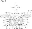
- Fig. 6 shows a sectional view, wherein the bolts 21a and 21b can be seen.
- the bolts 21a and 21b are movably supported in a receiving space 28 of the holder 18.
- a spring 29a loads the bolt 21a in the direction y2 into the locking position and a spring 29b loads the bolt 21b in the direction y1 into the locking position.
- An actuating element 30 is mounted pivotably about an axis a in the directions u1 and u2.
- the actuating element 30 can be attached to the headrest 10 from the outside with a button 43 (only in Fig. 2 or alternatively or additionally electrically operated by a motor.
- the operating member 30 comprises two arms 31 and 32. The arm 31 is in contact with the latch 21a and the arm 32 is in contact with the latch 21b.
- the illustrated basic position of the actuating element 30 are the bolts 21a and 21b in the bolt position. If the actuating element 30 is pivoted in direction u1, the arm 31 displaces the latch 21a against the force of the spring 29a in the direction y1 and the arm 32 displaces the latch 21b against the force of the spring 29b in the direction y2 into the release position. In the release position, the bolt 21a is out of engagement with the locking area 20a and the bolt 21b is out of engagement with the locking area 20b. In the release position, the head rest 11 can be moved between the rear position and the front position.
- the spring moves the bolt 21a in the direction y2 and the spring 29b moves the bolt 21b in the direction y1 into the bolt position in engagement with the respective bolt area 20a or 20b.
- the actuating element 30 is thereby moved back into the basic position by the bolts 21a and 21b in the direction u2.
- Fig. 6 hook-shaped projections 39a and 39b can be seen which are formed on the front region 25 of the holder 18. Grooves 41a and 41b are formed in the head support plate 27. The projection 39a engages in the groove 41a and the projection 39b engages in the groove 41b in order to guide the head support plate 27 so as to be movable relative to the holder 18 in directions z1 and z2. The projections 39a and 39b and the grooves 41a and 41b are part of the guide device 26. In the Fig. 2 and 3 a toothed splint 42 can be seen as part of the locking device, with which a bolt (not shown), mounted on the holder 18, can be releasably engaged in order to lock the head support plate 27 in different height positions.
- a toothed splint 42 can be seen as part of the locking device, with which a bolt (not shown), mounted on the holder 18, can be releasably engaged in order to lock the head support plate 27 in different height positions.
Landscapes
- Engineering & Computer Science (AREA)
- Aviation & Aerospace Engineering (AREA)
- Transportation (AREA)
- Mechanical Engineering (AREA)
- Chair Legs, Seat Parts, And Backrests (AREA)
Description
- Die Erfindung betrifft eine Kopfstütze, insbesondere für einen Fahrzeugsitz, mit Viergelenk-Lagerung.
- Eine solche Kopfstütze ist bekannt aus der
DE 10 2010 007 942 A1 . Die Kopfstütze umfasst eine Haltevorrichtung, mit welcher eine Kopfanlage an einem Fahrzeugsitz lagerbar ist. Zwischen der Kopfanlage und der Haltevorrichtung ist ein Viergelenk angeordnet, mit welchem die Kopfanlage zwischen einer vorderen Position und einer hinteren Position bewegbar ist. - Die Kopfanlage ist bei der Bewegung zwischen der vorderen Position und der hinteren Position in unterschiedlichen Positionen verriegelbar. Dafür sind die Lenker des Viergelenks kreisabschnittförmig geformt und umfassen an einem Endbereich eine Verzahnung mit welcher zur Verriegelung der Kopfanlage ein an der Haltevorrichtung schwenkbar gelagerter Hebel formschlüssig lösbar in Eingriff gebracht werden kann.
-
WO 2017/111310 A1 betrifft eine Kopfstütze mit einer Haltevorrichtung und einem Kopfanlageteil, wobei das Kopfanlageteil mittels eines ersten Lenkerpaares und mittels eines zweiten Lenkerpaares an der Haltevorrichtung bewegbar gelagert ist. Das Kopfanlageteil ist mittels einer Verriegelungsvorrichtung in unterschiedlichen Positionen verriegelbar. -
DE 10 2015 206 956 A1 betrifft eine Kopfstütze mit einer Haltevorrichtung und einem zwischen einer hinteren Position und einer vorderen Position bewegbarem Kopfanlageteil. Das Kopfanlageteil ist mittels eines ersten Lenkerpaares sowie eines zweiten Lenkerpaares an der Haltevorrichtung gelagert, wobei die Lenker Schwenkgelenke mit der Haltevorrichtung und mit dem Kopfanlageteil bilden. Die Verstellung erfogt mittels eines Stellgliedes 94, umfassend einen Elektromotor 156. - Es war Aufgabe der Erfindung eine Kopfstütze mit einem Viergelenk zu schaffen, die einen geringen Bauraum erfordert und lateral betrachtet optisch, insbesondere im Bereich der Haltevorrichtung, schmalbauend ist.
- Die Aufgabe wurde gelöst durch eine Kopfstütze mit den Merkmalen des Anspruchs 1.
- Die Kopfstütze ist für einen Sitz, insbesondere für einen Fahrzeugsitz, vorgesehen. Sie ist mit einer Kopfanlage sowie mit einer Haltevorrichtung zur Lagerung der Kopfstütze an einer Struktur des Fahrzeugs ausgestattet. Die Struktur des Fahrzeugs kann z.B. ein Fahrzeugsitz, insbesondere die Rückenlehne eines Fahrzeugsitzes sein. Haltevorrichtung kann jede Struktur sein, mit welcher eine Befestigung an der Fahrzeugstruktur möglich ist. Die Kopfstütze umfasst wenigstens ein Viergelenk zwischen der Kopfanlage und der Haltevorrichtung mittels welcher die Kopfanlage relativ zu der Haltevorrichtung zwischen einer ersten Position und einer zweiten Position bewegbar gelagert ist.
- Das Viergelenk umfasst wenigstens zwei Lenker, wobei jeder Lenker wenigstens ein Gelenk mit der Haltevorrichtung und wenigstens ein Gelenk mit der Kopfanlage bildet. Außerdem umfasst diie Kopfstütze wenigstens eine Verriegelungsvorrichtung, die mit der Haltevorrichtung zugeordneten ersten Verriegelungsmitteln und der Kopfanlage zugeordneten zweiten Verriegelungsmitteln versehen ist.
- Die ersten Verriegelungsmittel sind fest an der Haltevorrichtung gehalten oder gemäß einer Alternative ist ein oberer Bereich wenigstens eines Lenkers mit den ersten Verriegelungsmitteln versehen. Die zweiten Verriegelungsmittel sind fest an der Kopfanlage gehalten.
- Die Haltevorrichtung umfasst z.B. wenigstens eine Tragstange oder einen Tragstangenbügel. Die Tragstange muss nicht im herkömmlichen Sinne eine Stange sein, sie kann z.B. im Sinne der Erfindung auch ein Blech sein. Die Haltevorrichtung kann z.B. ein etwa U-förmiges Blech mit freien Endbereichen umfassen. An den Endbereichen sind z.B. Lenker des Viergelenks angelenkt. Das Blech ist z.B. an wenigstens einer Tragstange oder an einem Tragstangenbügel gelagert, wobei die Tragstange oder der Tragstangenbügel an der Rückenlehne gelagert werden kann. Das Blech kann z.B. auch unmittelbar an der Rückenlehne gehalten sein. Alternativ kann die Haltevorrichtung z.B. auch einfach von einer Grundplatte gebildet sein, die an der Lehnenstruktur befestigbar ist. Die Haltevorrichtung bildet z.B. die ersten Verriegelungsmittel aus.
- Die Kopfanlage umfasst z.B. einen Halter. Der Halter bildet z.B. die Gelenke zwischen den Lenkern des Viergelenks und der Kopfanlage aus. Der Halter ist z.B. einteilig mit einer Kopfanlageplatte verbunden oder als separates Teil ausgebildet. In letzterem Fall kann die Kopfanlageplatte relativ zu dem Halter bewegbar sein. Der Halter nimmt z.B. einen Teil der Verriegelungsvorrichtung auf.
- Gemäß der Erfindung umfasst die Haltevorrichtung wenigstens einen sich über die kopfanlageseitigen Gelenke erstreckenden Vorsprung. Der Vorsprung kann z.B. von einer Tragstange oder einem Tragstangenbügel gebildet sein. Der Vorsprung erstreckt sich z.B. von der Haltevorrichtung etwa vertikal. Mit diesen Merkmalen können die ersten Verriegelungsmittel benachbart den zweiten Verriegelungsmitteln ausgebildet werden. Es muss kein großer Weg zwischen den ersten Verriegelungsmitteln und den zweiten Verriegelungsmitteln überbrückt werden, um diese zwischen der Riegelposition und der Löseposition zu bewegen.
- Die ersten Verriegelungsmittel sind dem Vorsprung zugeordnet. Der Vorsprung bildet die ersten Verriegelungsmittel z.B. aus. Z.B. sind die ersten Verriegelungsmittel von einem Bereich des Vorsprungs gebildet oder von einem an dem Vorsprung befestigten Element.
- Die zweiten Verriegelungsmittel umfassen z.B. wenigstens einen zwischen der Riegelposition und der Löseposition verlagerbaren Riegel. Der Riegel kann z.B. die Form wenigstens eines Vorsprungs aufweisen, der in eine Aussparung der ersten Verriegelungsmittel eingreift oder wenigstens eine Aussparung umfassen, die formschlüssig lösbar in Eingriff mit einer Struktur der ersten Verriegelungsmittel bewegbar ist.
- Der wenigstens eine Riegel ist z.B. von wenigstens einer Zahnschiene gebildet, die mit wenigstens einer Aussparung versehen ist. In diesem Fall kann dann wahlweise eine der Aussparungen lösbar in Eingriff mit den ersten Verriegelungsmitteln bewegbar sein, z.B. mit einem Bereich eines Vorsprungs der Haltevorrichtung, welcher die ersten Verriegelungsmittel bildet.
- Einer Ausführungsform gemäß ist die Zahnschiene im Wesentlichen in einer im Wesentlichen horizontalen Ebene zwischen der Riegelposition und der Löseposition verlagerbar, um die Verriegelungsvorrichtung zwischen der Riegelposition und der Löseposition zu bewegen.
- Z.B. sind die ersten Verriegelungsmittel von zwei an der Haltevorrichtung umfassten Vorsprüngen und die zweiten Verriegelungsmittel von zwei an der Kopfanlage gelagerten Zahnschienen gebildet.
- Die Zahnschiene ist z.B. von einem Riegelelement gebildet. Das Riegelelement ist z.B. translatorisch verlagerbar.
- Gemäß einer Ausführungsform sind die Riegel von einer Feder in die Riegelposition belastet und sind entgegen der Kraft der Feder in die Löseposition bewegbar.
- Z.B. ist die Verriegelungsvorrichtung benachbart der kopfanlageseitigen Gelenke des Viergelenks angeordnet. Mit diesen Merkmalen werden die auf die Haltevorrichtung wirkenden Hebelkräfte verringert. Z.B. ist die Verriegelungsvorrichtung, insbesondere die zweiten Verriegelungsmittel, oberhalb der kopfanlageseitigen Gelenke des Viergelenks angeordnet.
- Zusätzlich zu der Horizontalverstellung der Kopfanlage weist die Kopfstütze z.B. eine Stelleinrichtung für eine vertikale Verstellung der gesamten Kopfanlage oder eines Teils der Kopfanlage auf.
- Die vertikale Verstellung der Kopfstütze kann z.B. entsprechend der Kopfstütze gemäß
DE 10 2017 007 149 A1 ausgebildet sein, deren Offenbarung vollumfänglich in diese Anmeldung übernommen wird. - Weitere Vorteile ergeben sich anhand eines in den Fig. schematisch dargestellten Ausführungsbeispieles. Es zeigen:
-
Fig. 1 eine perspektivische Darstellung der Kopfstütze von vorne, wobei sich eine Kopfanlage in der hinteren Position befindet -
Fig. 2 eine perspektivische Darstellung der Kopfstütze gemäßFig. 1 von hinten, -
Fig. 3 eine Rückansicht der Kopfstütze gemäßFig. 1 , -
Fig. 4 eine Schnittansicht gemäß Schnittlinie A - A inFig. 3 , -
Fig. 5 eine Schnittansicht in Anlehnung anFig. 4 , wobei die Kopfanlage in einer zweiten Position angeordnet ist, -
Fig. 6 eine Schnittansicht gemäß Schnittlinie B - B inFig. 3 . - Eine Kopfstütze eines Fahrzeugsitzes insgesamt ist in den Fig. mit dem Bezugszeichen 10 bezeichnet. Gleiche Bezugszeichen in den unterschiedlichen Fig. bezeichnen entsprechende Teile, auch wenn kleine Buchstaben nachgestellt oder weggelassen sind.
- Eine perspektivische Ansicht der Kopfstütze 10 ist in
Fig. 1 dargestellt. Die Kopfstütze 10 umfasst eine Kopfanlage 11 sowie eine Haltevorrichtung 12, welche im vorliegenden Ausführungsbeispiel zwei Tragstangen 13a und 13b umfasst. Die Kopfanlage 11 umfasst eine Kopfanlageplatte 27 sowie einen Halter 18, der im vorliegenden Ausführungsbeispiel ein separates Teil ist, alternativ aber auch einteilig mit der Kopfanlageplatte 27 verbunden sein kann. Die Tragstangen 13a und 13b sind zur Stabilisierung mit einer Stange 37 zu einem Tragstangenbügel 38 fest verbunden, die Teil der Haltevorrichtung 12 ist. Die Kopfanlage 11 weist eine Kopfanlagefläche 14 auf, die ein Widerlager für den Kopf des Sitzinsassen bildet. - Untere Enden 15a und 15b der Tragstangen 13a und 13b sind z.B. an der Struktur Rückenlehne eines nicht dargestellten Sitzes befestigbar. Die Kopfanlage 11 ist mittels einer Verstellvorrichtung 40 in unterschiedliche Positionen verstellbar. Die Verstellvorrichtung 40 umfasst eine Viergelenkvorrichtung 23 mit zwei Lenkern 16 und 17. Jeder der Lenker 16 und 17 umfasst Arme 34a und 34b sowie eine Traverse 33, welche die Arme 34a und 34b verbindet. Die Traverse 33 dient bei dem Ausführungsbeispiel im Wesentlichen der Verbesserung der Stabilität. Die Traverse 33 als Verbindung der Arme 34a und 34b könnte aber alternativ auch entfallen.
- Der Lenker 16 bildet mit der Tragstange 13b ein Gelenk G1 (siehe
Fig. 2 ) und der Lenker 17 bildet mit der Tragstange 13b ein Gelenk G2. Der Lenker 16, insbesondere der Arm 34b des Lenkers 16, bildet außerdem mit der Kopfanlage 11, im vorliegenden Fall mit einem Seitenbereich 35 des Halters 18 der Kopfanlage 11, ein Gelenk G3, während der Lenker 17, insbesondere der Arm 34b des Lenkers 17, mit dem Seitenbereich 35 des Halters 18 ein Gelenk G4 bildet. - In gleicher Weise bilden die Lenker 16 und 17 an einem dem Seitenbereich 35 gegenüberliegenden Seitenbereich 36 jeweils ein Gelenk mit der Tragstange 13a und darüber hinaus jeweils ein Gelenk mit dem Halter 18, was in
Fig. 2 nicht erkennbar ist. - Auf diese Weise ist die Kopfanlage 11 mittels einer Viergelenkvorrichtung 23 umfassend den Tragstangenbügel 38, die Lenker 16 und 17 sowie die Kopfanlage 11 mit dem Halter 18 relativ zu der Haltevorrichtung 12 zwischen einer hinteren Position (siehe die
Fig. 2 bis 4 ) und einer vorderen Position (sieheFig. 5 ) in die Richtungen x1 und x2 verlagerbar, wobei die Kopfanlage 11 dabei eine Kurvenbewegung ausführt mit Anteilen einer Bewegung in Z-Richtung und Anteilen einer Bewegung in X-Richtung. - Die Verstellvorrichtung 40 umfasst eine Verriegelungsvorrichtung 19, mit welcher die Kopfanlage 11 in der hinteren Position oder der vorderen Position oder in einer Position zwischen der hinteren Position und der vorderen Position arretierbar ist. Die Verriegelungsvorrichtung 19 umfasst der Kopfanlage 11 zugeordnete erste Verriegelungsmittel und den Tragstangen 13a und 13b zugeordnete zweite Verriegelungsmittel, welche lösbar in Eingriff gebracht werden können.
- Im vorliegenden Fall sind die Tragstangen 13a und 13b über die Gelenke G1 und G2 hinaus, insbesondere über die Gelenke G3 und G4 hinaus, in Richtung z1 verlängert und sind mit den zweiten Verriegelungsmitteln in Form eines Riegelbereichs 20 versehen. Der Riegelbereich 20 ist im vorliegenden Ausführungsbeispiel unmittelbar von den Tragstangen 13a und 13b gebildet. Die ersten Verriegelungsmittel sind in Form zweier Riegel 21a und 21b ausgebildet, die relativ zu dem Halter 18 bewegbar sind und jeweils mit einer Zahnstruktur 22a und 22b, in diesem Ausführungsbeispiel in Form einer Zahnschiene, versehen sind. In
Fig. 2 ist lediglich die Zahnstruktur 22b erkennbar. - In
Fig. 2 ist ebenfalls erkennbar, dass sich die Verriegelungsvorrichtung 19 in einer Riegelposition befindet, d.h., dass die Zahnstruktur 22b mit dem Riegelbereich 20 in Eingriff steht, so dass die Kopfanlage 11 nicht zwischen der hinteren und der vorderen Position bewegbar ist. - In
Fig. 3 ist die gelenkige Verbindung zwischen dem Lenker 17 und der Tragstange 13a in Form eines Gelenks G5 zu erkennen. - Ein hinterer Bereich 24 des Halters 18 umfasst die Zahnstrukturen 22a und 22b, welche sich im Wesentlichen in x-Richtung erstrecken. Ein vorderer Bereich 25 ist mit einer Führungsvorrichtung 26 versehen, um die Kopfanlageplatte 27 in Richtung z1 und z2 zwischen einer oberen Position und einer unteren Position bewegbar zu lagern. Die Kopfanlageplatte 27 kann mit einer Arretiervorrichtung in der oberen Position, der unteren Position und in Zwischenpositionen zwischen der oberen Position und der unteren Position arretiert werden.
- Gemäß
Fig. 4 ist die Kopfanlage 11 in der hinteren Position mittels der Verriegelungsvorrichtung 23 verriegelt.Fig. 5 zeigt die Kopfanlage 11 in der vorderen Position verriegelt. -
Fig. 6 zeigt eine Schnittansicht, wobei die Riegel 21a und 21b erkennbar sind. In einem Aufnahmeraum 28 des Halters 18 sind die Riegel 21a und 21b bewegbar gelagert. Eine Feder 29a belastet den Riegel 21a in Richtung y2 in die Riegelposition und eine Feder 29b belastet den Riegel 21b in Richtung y1 in die Riegelposition. - Ein Betätigungselement 30 ist um eine Achse a in die Richtungen u1 und u2 schwenkbar gelagert. Das Betätigungselement 30 kann von außen an der Kopfstütze 10 mit einer Taste 43 (lediglich in
Fig. 2 bezeichnet) oder alternativ oder zusätzlich elektrisch mit einem Motor betätigt werden. Das Betätigungselement 30 umfasst zwei Arme 31 und 32. Der Arm 31 steht mit dem Riegel 21a in Kontakt und der Arm 32 steht mit dem Riegel 21b in Kontakt. - In der in
Fig. 6 dargestellten Grundposition des Betätigungselements 30 befinden sich die Riegel 21a und 21b in der Riegelposition. Wird das Betätigungselement 30 in Richtung u1 geschwenkt, verlagert der Arm 31 den Riegel 21a entgegen der Kraft der Feder 29a in Richtung y1 und der Arm 32 verlagert den Riegel 21b entgegen der Kraft der Feder 29b in Richtung y2 in die Löseposition. In der Löseposition steht der Riegel 21a außer Eingriff mit dem Riegelbereich 20a und der Riegel 21b steht außer Eingriff mit dem Riegelbereich 20b. In der Löseposition kann die Kopfanlage 11 zwischen der hinteren Position und der vorderen Position bewegt werden. - Wird das Betätigungselement 30 entlastet, bewegt die Feder den Riegel 21a in Richtung y2 und die Feder 29b bewegt den Riegel 21b in Richtung y1 in die Riegelposition in Eingriff mit dem jeweiligen Riegelbereich 20a bzw. 20b. Dabei wird das Betätigungselement 30 von den Riegeln 21a und 21b in Richtung u2 in die Grundposition zurückbewegt.
- In
Fig. 6 sind Hakenförmige Vorsprünge 39a und 39b erkennbar, die an dem vorderen Bereich 25 des Halters 18 ausgebildet sind. In der Kopfanlageplatte 27 sind Nuten 41a und 41b ausgebildet. Der Vorsprung 39a greift in die Nut 41a und der Vorsprung 39b greift in die Nut 41b, um die Kopfanlageplatte 27 relativ zu dem Halter 18 in Richtung z1 und z2 bewegbar zu führen. Die Vorsprünge 39a und 39b sowie die Nuten 41a und 41b sind Teil der Führungsvorrichtung 26. In denFig. 2 und3 ist eine Zahnschiene 42 als Teil der Arretiervorrichtung erkennbar, mit welcher ein nicht dargestellter, an dem Halter 18 gelagerter Riegel lösbar in Eingriff gebracht werden kann, um die Kopfanlageplatte 27 in unterschiedlichen Höhenpositionen zu arretieren.
Claims (8)
- Kopfstütze, insbesondere für einen Fahrzeugsitz, mit einer Kopfanlage (11), mit einer Haltevorrichtung (12) zur Lagerung der Kopfstütze (10) an einer festen Struktur, mit wenigstens einem Viergelenk (23) zwischen der Kopfanlage (11) und der Haltevorrichtung (12) mittels welcher die Kopfanlage (11) relativ zu der Haltevorrichtung (12) zwischen einer ersten Position und einer zweiten Position bewegbar gelagert ist, wobei das Viergelenk (23) wenigstens zwei Lenker (16, 17) umfasst, und jeder Lenker (16, 17) wenigstens ein Gelenk (G1A, G2A, G1C, G2C) mit der Haltevorrichtung (12) und wenigstens ein Gelenk (G1B, G2B, G1D, G2D) mit der Kopfanlage (11) bildet, mit einer Verriegelungsvorrichtung (19), mit der Haltevorrichtung (12) zugeordneten ersten Verriegelungsmitteln und der Kopfanlage (11) zugeordneten zweiten Verriegelungsmitteln, wobei die ersten Verriegelungsmittel und die zweiten Verriegelungsmittel in einer Riegelposition in Eingriff stehen und in einer Löseposition außer Eingriff sind, wobei die ersten Verriegelungsmittel fest an der Haltevorrichtung (12) gehalten sind und die zweiten Verriegelungsmittel fest an der Kopfanlage (11) gehalten sind, dadurch gekennzeichnet, dass die Haltevorrichtung (12) wenigstens einen sich über die kopfanlageseitigen Gelenke (G1B, G2B, G1D, G2D) erstreckenden Vorsprung (V) umfasst und dass die ersten Verriegelungsmittel dem Vorsprung zugeordnet sind.
- Kopfstütze nach Anspruch 1, dadurch gekennzeichnet, dass die Haltevorrichtung (12) wenigstens eine Tragstange (13a, 13b) oder einen Tragstangenbügel umfasst.
- Kopfstütze nach einem der vorangehenden Ansprüche, dadurch gekennzeichnet, dass die zweiten Verriegelungsmittel wenigstens einen zwischen der Riegelposition und der Löseposition verlagerbaren Riegel (21a, 21b) umfassen.
- Kopfstütze nach einem der vorangehenden Ansprüche, dadurch gekennzeichnet, dass der wenigstens eine Riegel (21a, 21b) von wenigstens einer Zahnstruktur (22a, 22b), insbesondere von einer Zahnschiene, gebildet ist, die mit wenigstens einer Aussparung versehen ist.
- Kopfstütze nach Anspruch 6, dadurch gekennzeichnet, dass die Zahnstruktur im Wesentlichen horizontal zwischen der Riegelposition und der Löseposition verlagerbar ist.
- Kopfstütze nach einem der vorangehenden Ansprüche, dadurch gekennzeichnet, dass die Haltevorrichtung (12) zwei Vorsprünge (V) umfasst und dass zwei parallel angeordnete Zahnstruktur (22a, 22b) vorgesehen sind.
- Kopfstütze nach Anspruch 4 oder Anspruch 5, dadurch gekennzeichnet, dass die Zahnstruktur benachbart der kopfanlageseitigen Gelenke (G1B, G2B, G1D, G2D) des Viergelenks (23) angeordnet sind.
- Kopfstütze nach einem der vorangehenden Ansprüche, dadurch gekennzeichnet, dass die Kopfanlage eine Stelleinrichtung (40) für eine vertikale Verstellung der Kopfanlage (11) oder eines Teils der Kopfanlage (11) aufweist.
Applications Claiming Priority (1)
| Application Number | Priority Date | Filing Date | Title |
|---|---|---|---|
| DE102018106698.8A DE102018106698A1 (de) | 2018-03-21 | 2018-03-21 | Kopfstütze |
Publications (2)
| Publication Number | Publication Date |
|---|---|
| EP3543068A1 EP3543068A1 (de) | 2019-09-25 |
| EP3543068B1 true EP3543068B1 (de) | 2020-11-11 |
Family
ID=65628509
Family Applications (1)
| Application Number | Title | Priority Date | Filing Date |
|---|---|---|---|
| EP19020091.5A Active EP3543068B1 (de) | 2018-03-21 | 2019-02-27 | Kopfstütze |
Country Status (4)
| Country | Link |
|---|---|
| US (1) | US10821866B2 (de) |
| EP (1) | EP3543068B1 (de) |
| CN (1) | CN110293889B (de) |
| DE (1) | DE102018106698A1 (de) |
Families Citing this family (4)
| Publication number | Priority date | Publication date | Assignee | Title |
|---|---|---|---|---|
| DE102018109611B4 (de) | 2018-04-10 | 2022-04-21 | Grammer Aktiengesellschaft | Kopfstütze |
| DE102018005316A1 (de) * | 2018-07-05 | 2020-01-09 | Grammer Aktiengesellschaft | Kopfstütze |
| DE102021128756A1 (de) | 2021-11-04 | 2023-05-04 | Bayerische Motoren Werke Aktiengesellschaft | Sitz |
| KR20250082019A (ko) * | 2023-11-28 | 2025-06-09 | 현대자동차주식회사 | 자동차용 헤드레스트 위치 조절 장치 |
Citations (1)
| Publication number | Priority date | Publication date | Assignee | Title |
|---|---|---|---|---|
| US8616633B2 (en) * | 2008-11-10 | 2013-12-31 | Grammer Ag | Headrest for a vehicle |
Family Cites Families (23)
| Publication number | Priority date | Publication date | Assignee | Title |
|---|---|---|---|---|
| JPS54127762A (en) * | 1978-03-24 | 1979-10-03 | Aisin Seiki | Frontttoorear direction adjuster for safety pillow of automobile |
| JPS61102153U (de) * | 1984-12-12 | 1986-06-30 | ||
| DE19941712C1 (de) * | 1999-09-02 | 2000-10-26 | Daimler Chrysler Ag | Fahrzeugsitz |
| DE19951966B4 (de) * | 1999-10-28 | 2006-11-02 | Bayerische Motoren Werke Ag | Fahrzeugsitz mit einer an der Rückenlehne oder am Fahrzeugaufbau vorgesehenen Kopfstütze |
| DE10047406A1 (de) * | 2000-09-26 | 2002-04-11 | Daimler Chrysler Ag | Kopfstütze |
| DE10125757A1 (de) * | 2001-05-18 | 2002-11-21 | Volkswagen Ag | Fahrzeugsitz mit einer in der Rückenlehne integrierten Kopfstütze |
| DE10348939B3 (de) * | 2003-10-18 | 2005-01-27 | Daimlerchrysler Ag | Kopfstütze für einen Fahrzeusitz |
| DE102004059237B3 (de) * | 2004-12-08 | 2006-02-23 | Grammer Ag | Kopfstütze für Fahrzeugsitze |
| JP4018713B2 (ja) * | 2005-11-17 | 2007-12-05 | アイシン精機株式会社 | ヘッドレスト装置 |
| ES1064266Y (es) * | 2006-12-05 | 2007-05-16 | Batz S Coop | Reposacabezas para asientos de vehiculos automoviles |
| DE102010007942B4 (de) * | 2010-02-12 | 2012-08-09 | Grammer Aktiengesellschaft | Kopfstütze für Fahrzeugsitze |
| DE102010010537B4 (de) * | 2010-03-05 | 2012-10-25 | Johnson Controls Gmbh | Kopfstütze, insbesondere für ein Kraftfahrzeug |
| DE102011102702B4 (de) * | 2011-05-20 | 2013-08-14 | Johnson Controls Gmbh | In X-Richtung verschiebliche Kopfstütze |
| US8746800B2 (en) * | 2011-08-23 | 2014-06-10 | Honda Motor Co., Ltd. | Vehicle head restraint assembly |
| FR3001669B1 (fr) * | 2013-02-07 | 2016-03-04 | Cera | Appui-tete de siege de vehicule automobile |
| DE102013014979A1 (de) * | 2013-09-10 | 2014-04-24 | Daimler Ag | Kopfstütze für einen Fahrzeugsitz |
| US9566884B2 (en) * | 2013-11-11 | 2017-02-14 | Ford Global Technologies, Llc | Powered head restraint electrical connector |
| KR101553527B1 (ko) * | 2014-03-17 | 2015-09-17 | 현대다이모스(주) | 전동식 헤드레스트 |
| BR102015008502A2 (pt) * | 2014-04-21 | 2015-10-27 | Ford Global Tech Llc | conector elétrico de apoio de cabeça motorizado |
| JP6396134B2 (ja) * | 2014-09-17 | 2018-09-26 | 株式会社東洋シート | ヘッドレスト |
| KR101694910B1 (ko) * | 2015-12-23 | 2017-01-10 | 주식회사 우보테크 | 헤드레스트 슬라이딩 장치 |
| DE102017001149B4 (de) * | 2017-02-08 | 2025-02-20 | Grammer Aktiengesellschaft | Kopfstütze |
| DE102017007149A1 (de) | 2017-07-27 | 2019-01-31 | DILO Armaturen und Anlagenbau GmbH | Verfahren zur Lokalisierung von Leckstellen |
-
2018
- 2018-03-21 DE DE102018106698.8A patent/DE102018106698A1/de active Pending
-
2019
- 2019-02-21 US US16/281,890 patent/US10821866B2/en active Active
- 2019-02-27 EP EP19020091.5A patent/EP3543068B1/de active Active
- 2019-03-20 CN CN201910210256.8A patent/CN110293889B/zh active Active
Patent Citations (1)
| Publication number | Priority date | Publication date | Assignee | Title |
|---|---|---|---|---|
| US8616633B2 (en) * | 2008-11-10 | 2013-12-31 | Grammer Ag | Headrest for a vehicle |
Also Published As
| Publication number | Publication date |
|---|---|
| US10821866B2 (en) | 2020-11-03 |
| US20190322200A1 (en) | 2019-10-24 |
| EP3543068A1 (de) | 2019-09-25 |
| DE102018106698A1 (de) | 2019-09-26 |
| CN110293889B (zh) | 2021-11-30 |
| CN110293889A (zh) | 2019-10-01 |
Similar Documents
| Publication | Publication Date | Title |
|---|---|---|
| EP3543068B1 (de) | Kopfstütze | |
| EP2746103B1 (de) | Nutzfahrzeugsitz mit doppelarretierbarem querschlittenteil | |
| DE102004005695B4 (de) | Fahrzeugsitz | |
| DE10348939B3 (de) | Kopfstütze für einen Fahrzeusitz | |
| DE60300049T2 (de) | Kopfstütze für Kraftfahrzeugsitze | |
| DE69204752T2 (de) | Vorrichtung zum Erhöhen eines Fahrzeugsitzkissens, welche eine Sicherheitsverriegelung aufweist. | |
| DE102011108652B4 (de) | Fahrzeugsitz, insbesondere Kraftfahrzeugsitz | |
| EP3250404B1 (de) | Antriebssystem für einen beweglichen dachteil eines dachmoduls eines kraftfahrzeugs | |
| EP2608988B1 (de) | Arretiervorrichtung für eine kopfstütze | |
| DE102013003867B4 (de) | Fahrzeugsitz umfassend eine Sitzflächenverlängerung | |
| DE19737304A1 (de) | Sitz, insbesondere für eine dritte Sitzreihe eines Kraftfahrzeuges | |
| DE102018109611B4 (de) | Kopfstütze | |
| EP3552875A1 (de) | Kopfstütze | |
| DE3500496A1 (de) | Koerpergewichtseinstellvorrichtung einer sitzaufhaengung | |
| DE102007027564A1 (de) | Fahrzeugsitz-Verstellvorrichtung | |
| EP3590760B1 (de) | Kopfstütze | |
| DE10238487B4 (de) | Fahrzeugsitz | |
| DE10236259B4 (de) | Kopfstütze für Fahrzeugsitze | |
| EP3360728B1 (de) | Kopfstütze | |
| WO2020144114A1 (de) | Antriebssystem für ein bewegliches dachteil eines dachsystems eines kraftfahrzeugs | |
| DE202004011388U1 (de) | Kraftfahrzeugsitz | |
| DE102005005826B4 (de) | Kopfstütze | |
| EP1514725B1 (de) | Verstelleinrichtung für einen Rücksitz eines Fahrzeuges | |
| DE102008045021B3 (de) | Kopfstütze für Fahrzeuge | |
| DE102009036896B3 (de) | Kopfstütze für Fahrzeugsitze |
Legal Events
| Date | Code | Title | Description |
|---|---|---|---|
| PUAI | Public reference made under article 153(3) epc to a published international application that has entered the european phase |
Free format text: ORIGINAL CODE: 0009012 |
|
| STAA | Information on the status of an ep patent application or granted ep patent |
Free format text: STATUS: THE APPLICATION HAS BEEN PUBLISHED |
|
| AK | Designated contracting states |
Kind code of ref document: A1 Designated state(s): AL AT BE BG CH CY CZ DE DK EE ES FI FR GB GR HR HU IE IS IT LI LT LU LV MC MK MT NL NO PL PT RO RS SE SI SK SM TR |
|
| AX | Request for extension of the european patent |
Extension state: BA ME |
|
| STAA | Information on the status of an ep patent application or granted ep patent |
Free format text: STATUS: REQUEST FOR EXAMINATION WAS MADE |
|
| 17P | Request for examination filed |
Effective date: 20191120 |
|
| RBV | Designated contracting states (corrected) |
Designated state(s): AL AT BE BG CH CY CZ DE DK EE ES FI FR GB GR HR HU IE IS IT LI LT LU LV MC MK MT NL NO PL PT RO RS SE SI SK SM TR |
|
| GRAJ | Information related to disapproval of communication of intention to grant by the applicant or resumption of examination proceedings by the epo deleted |
Free format text: ORIGINAL CODE: EPIDOSDIGR1 |
|
| STAA | Information on the status of an ep patent application or granted ep patent |
Free format text: STATUS: GRANT OF PATENT IS INTENDED |
|
| GRAP | Despatch of communication of intention to grant a patent |
Free format text: ORIGINAL CODE: EPIDOSNIGR1 |
|
| INTG | Intention to grant announced |
Effective date: 20200804 |
|
| GRAS | Grant fee paid |
Free format text: ORIGINAL CODE: EPIDOSNIGR3 |
|
| GRAA | (expected) grant |
Free format text: ORIGINAL CODE: 0009210 |
|
| STAA | Information on the status of an ep patent application or granted ep patent |
Free format text: STATUS: THE PATENT HAS BEEN GRANTED |
|
| AK | Designated contracting states |
Kind code of ref document: B1 Designated state(s): AL AT BE BG CH CY CZ DE DK EE ES FI FR GB GR HR HU IE IS IT LI LT LU LV MC MK MT NL NO PL PT RO RS SE SI SK SM TR |
|
| REG | Reference to a national code |
Ref country code: GB Ref legal event code: FG4D Free format text: NOT ENGLISH |
|
| REG | Reference to a national code |
Ref country code: CH Ref legal event code: EP |
|
| REG | Reference to a national code |
Ref country code: AT Ref legal event code: REF Ref document number: 1333140 Country of ref document: AT Kind code of ref document: T Effective date: 20201115 |
|
| REG | Reference to a national code |
Ref country code: DE Ref legal event code: R096 Ref document number: 502019000375 Country of ref document: DE |
|
| REG | Reference to a national code |
Ref country code: IE Ref legal event code: FG4D Free format text: LANGUAGE OF EP DOCUMENT: GERMAN |
|
| RAP2 | Party data changed (patent owner data changed or rights of a patent transferred) |
Owner name: GRAMMER AG |
|
| REG | Reference to a national code |
Ref country code: NL Ref legal event code: MP Effective date: 20201111 |
|
| PG25 | Lapsed in a contracting state [announced via postgrant information from national office to epo] |
Ref country code: FI Free format text: LAPSE BECAUSE OF FAILURE TO SUBMIT A TRANSLATION OF THE DESCRIPTION OR TO PAY THE FEE WITHIN THE PRESCRIBED TIME-LIMIT Effective date: 20201111 Ref country code: RS Free format text: LAPSE BECAUSE OF FAILURE TO SUBMIT A TRANSLATION OF THE DESCRIPTION OR TO PAY THE FEE WITHIN THE PRESCRIBED TIME-LIMIT Effective date: 20201111 Ref country code: PT Free format text: LAPSE BECAUSE OF FAILURE TO SUBMIT A TRANSLATION OF THE DESCRIPTION OR TO PAY THE FEE WITHIN THE PRESCRIBED TIME-LIMIT Effective date: 20210311 Ref country code: NO Free format text: LAPSE BECAUSE OF FAILURE TO SUBMIT A TRANSLATION OF THE DESCRIPTION OR TO PAY THE FEE WITHIN THE PRESCRIBED TIME-LIMIT Effective date: 20210211 Ref country code: GR Free format text: LAPSE BECAUSE OF FAILURE TO SUBMIT A TRANSLATION OF THE DESCRIPTION OR TO PAY THE FEE WITHIN THE PRESCRIBED TIME-LIMIT Effective date: 20210212 |
|
| PG25 | Lapsed in a contracting state [announced via postgrant information from national office to epo] |
Ref country code: BG Free format text: LAPSE BECAUSE OF FAILURE TO SUBMIT A TRANSLATION OF THE DESCRIPTION OR TO PAY THE FEE WITHIN THE PRESCRIBED TIME-LIMIT Effective date: 20210211 Ref country code: LV Free format text: LAPSE BECAUSE OF FAILURE TO SUBMIT A TRANSLATION OF THE DESCRIPTION OR TO PAY THE FEE WITHIN THE PRESCRIBED TIME-LIMIT Effective date: 20201111 Ref country code: PL Free format text: LAPSE BECAUSE OF FAILURE TO SUBMIT A TRANSLATION OF THE DESCRIPTION OR TO PAY THE FEE WITHIN THE PRESCRIBED TIME-LIMIT Effective date: 20201111 Ref country code: IS Free format text: LAPSE BECAUSE OF FAILURE TO SUBMIT A TRANSLATION OF THE DESCRIPTION OR TO PAY THE FEE WITHIN THE PRESCRIBED TIME-LIMIT Effective date: 20210311 Ref country code: SE Free format text: LAPSE BECAUSE OF FAILURE TO SUBMIT A TRANSLATION OF THE DESCRIPTION OR TO PAY THE FEE WITHIN THE PRESCRIBED TIME-LIMIT Effective date: 20201111 |
|
| REG | Reference to a national code |
Ref country code: LT Ref legal event code: MG9D |
|
| PG25 | Lapsed in a contracting state [announced via postgrant information from national office to epo] |
Ref country code: HR Free format text: LAPSE BECAUSE OF FAILURE TO SUBMIT A TRANSLATION OF THE DESCRIPTION OR TO PAY THE FEE WITHIN THE PRESCRIBED TIME-LIMIT Effective date: 20201111 |
|
| PG25 | Lapsed in a contracting state [announced via postgrant information from national office to epo] |
Ref country code: RO Free format text: LAPSE BECAUSE OF FAILURE TO SUBMIT A TRANSLATION OF THE DESCRIPTION OR TO PAY THE FEE WITHIN THE PRESCRIBED TIME-LIMIT Effective date: 20201111 Ref country code: LT Free format text: LAPSE BECAUSE OF FAILURE TO SUBMIT A TRANSLATION OF THE DESCRIPTION OR TO PAY THE FEE WITHIN THE PRESCRIBED TIME-LIMIT Effective date: 20201111 Ref country code: SK Free format text: LAPSE BECAUSE OF FAILURE TO SUBMIT A TRANSLATION OF THE DESCRIPTION OR TO PAY THE FEE WITHIN THE PRESCRIBED TIME-LIMIT Effective date: 20201111 Ref country code: SM Free format text: LAPSE BECAUSE OF FAILURE TO SUBMIT A TRANSLATION OF THE DESCRIPTION OR TO PAY THE FEE WITHIN THE PRESCRIBED TIME-LIMIT Effective date: 20201111 Ref country code: EE Free format text: LAPSE BECAUSE OF FAILURE TO SUBMIT A TRANSLATION OF THE DESCRIPTION OR TO PAY THE FEE WITHIN THE PRESCRIBED TIME-LIMIT Effective date: 20201111 Ref country code: CZ Free format text: LAPSE BECAUSE OF FAILURE TO SUBMIT A TRANSLATION OF THE DESCRIPTION OR TO PAY THE FEE WITHIN THE PRESCRIBED TIME-LIMIT Effective date: 20201111 |
|
| REG | Reference to a national code |
Ref country code: DE Ref legal event code: R097 Ref document number: 502019000375 Country of ref document: DE |
|
| PG25 | Lapsed in a contracting state [announced via postgrant information from national office to epo] |
Ref country code: DK Free format text: LAPSE BECAUSE OF FAILURE TO SUBMIT A TRANSLATION OF THE DESCRIPTION OR TO PAY THE FEE WITHIN THE PRESCRIBED TIME-LIMIT Effective date: 20201111 |
|
| PLBE | No opposition filed within time limit |
Free format text: ORIGINAL CODE: 0009261 |
|
| STAA | Information on the status of an ep patent application or granted ep patent |
Free format text: STATUS: NO OPPOSITION FILED WITHIN TIME LIMIT |
|
| PG25 | Lapsed in a contracting state [announced via postgrant information from national office to epo] |
Ref country code: MC Free format text: LAPSE BECAUSE OF FAILURE TO SUBMIT A TRANSLATION OF THE DESCRIPTION OR TO PAY THE FEE WITHIN THE PRESCRIBED TIME-LIMIT Effective date: 20201111 |
|
| 26N | No opposition filed |
Effective date: 20210812 |
|
| REG | Reference to a national code |
Ref country code: BE Ref legal event code: MM Effective date: 20210228 |
|
| PG25 | Lapsed in a contracting state [announced via postgrant information from national office to epo] |
Ref country code: LU Free format text: LAPSE BECAUSE OF NON-PAYMENT OF DUE FEES Effective date: 20210227 Ref country code: AL Free format text: LAPSE BECAUSE OF FAILURE TO SUBMIT A TRANSLATION OF THE DESCRIPTION OR TO PAY THE FEE WITHIN THE PRESCRIBED TIME-LIMIT Effective date: 20201111 Ref country code: NL Free format text: LAPSE BECAUSE OF FAILURE TO SUBMIT A TRANSLATION OF THE DESCRIPTION OR TO PAY THE FEE WITHIN THE PRESCRIBED TIME-LIMIT Effective date: 20201111 |
|
| PG25 | Lapsed in a contracting state [announced via postgrant information from national office to epo] |
Ref country code: SI Free format text: LAPSE BECAUSE OF FAILURE TO SUBMIT A TRANSLATION OF THE DESCRIPTION OR TO PAY THE FEE WITHIN THE PRESCRIBED TIME-LIMIT Effective date: 20201111 |
|
| PG25 | Lapsed in a contracting state [announced via postgrant information from national office to epo] |
Ref country code: IE Free format text: LAPSE BECAUSE OF NON-PAYMENT OF DUE FEES Effective date: 20210227 Ref country code: ES Free format text: LAPSE BECAUSE OF FAILURE TO SUBMIT A TRANSLATION OF THE DESCRIPTION OR TO PAY THE FEE WITHIN THE PRESCRIBED TIME-LIMIT Effective date: 20201111 |
|
| PG25 | Lapsed in a contracting state [announced via postgrant information from national office to epo] |
Ref country code: IS Free format text: LAPSE BECAUSE OF FAILURE TO SUBMIT A TRANSLATION OF THE DESCRIPTION OR TO PAY THE FEE WITHIN THE PRESCRIBED TIME-LIMIT Effective date: 20210311 |
|
| PG25 | Lapsed in a contracting state [announced via postgrant information from national office to epo] |
Ref country code: BE Free format text: LAPSE BECAUSE OF NON-PAYMENT OF DUE FEES Effective date: 20210228 |
|
| REG | Reference to a national code |
Ref country code: CH Ref legal event code: PL |
|
| PG25 | Lapsed in a contracting state [announced via postgrant information from national office to epo] |
Ref country code: LI Free format text: LAPSE BECAUSE OF NON-PAYMENT OF DUE FEES Effective date: 20220228 Ref country code: CH Free format text: LAPSE BECAUSE OF NON-PAYMENT OF DUE FEES Effective date: 20220228 |
|
| PG25 | Lapsed in a contracting state [announced via postgrant information from national office to epo] |
Ref country code: CY Free format text: LAPSE BECAUSE OF FAILURE TO SUBMIT A TRANSLATION OF THE DESCRIPTION OR TO PAY THE FEE WITHIN THE PRESCRIBED TIME-LIMIT Effective date: 20201111 |
|
| PG25 | Lapsed in a contracting state [announced via postgrant information from national office to epo] |
Ref country code: HU Free format text: LAPSE BECAUSE OF FAILURE TO SUBMIT A TRANSLATION OF THE DESCRIPTION OR TO PAY THE FEE WITHIN THE PRESCRIBED TIME-LIMIT; INVALID AB INITIO Effective date: 20190227 |
|
| PG25 | Lapsed in a contracting state [announced via postgrant information from national office to epo] |
Ref country code: MK Free format text: LAPSE BECAUSE OF FAILURE TO SUBMIT A TRANSLATION OF THE DESCRIPTION OR TO PAY THE FEE WITHIN THE PRESCRIBED TIME-LIMIT Effective date: 20201111 |
|
| PG25 | Lapsed in a contracting state [announced via postgrant information from national office to epo] |
Ref country code: MT Free format text: LAPSE BECAUSE OF FAILURE TO SUBMIT A TRANSLATION OF THE DESCRIPTION OR TO PAY THE FEE WITHIN THE PRESCRIBED TIME-LIMIT Effective date: 20201111 |
|
| REG | Reference to a national code |
Ref country code: AT Ref legal event code: MM01 Ref document number: 1333140 Country of ref document: AT Kind code of ref document: T Effective date: 20240227 |
|
| PG25 | Lapsed in a contracting state [announced via postgrant information from national office to epo] |
Ref country code: AT Free format text: LAPSE BECAUSE OF NON-PAYMENT OF DUE FEES Effective date: 20240227 |
|
| PGFP | Annual fee paid to national office [announced via postgrant information from national office to epo] |
Ref country code: GB Payment date: 20260219 Year of fee payment: 8 |
|
| PGFP | Annual fee paid to national office [announced via postgrant information from national office to epo] |
Ref country code: DE Payment date: 20260217 Year of fee payment: 8 |
|
| PGFP | Annual fee paid to national office [announced via postgrant information from national office to epo] |
Ref country code: AT Payment date: 20260410 Year of fee payment: 5 |
|
| PGFP | Annual fee paid to national office [announced via postgrant information from national office to epo] |
Ref country code: IT Payment date: 20260227 Year of fee payment: 8 |
|
| PGFP | Annual fee paid to national office [announced via postgrant information from national office to epo] |
Ref country code: FR Payment date: 20260223 Year of fee payment: 8 |
|
| PGFP | Annual fee paid to national office [announced via postgrant information from national office to epo] |
Ref country code: TR Payment date: 20260220 Year of fee payment: 8 |