EP3542918B1 - Vorrichtung und verfahren zur verbesserung der rückwärtsfliessung von wellen - Google Patents
Vorrichtung und verfahren zur verbesserung der rückwärtsfliessung von wellen Download PDFInfo
- Publication number
- EP3542918B1 EP3542918B1 EP19164061.4A EP19164061A EP3542918B1 EP 3542918 B1 EP3542918 B1 EP 3542918B1 EP 19164061 A EP19164061 A EP 19164061A EP 3542918 B1 EP3542918 B1 EP 3542918B1
- Authority
- EP
- European Patent Office
- Prior art keywords
- mandrel
- work piece
- catcher
- rollers
- various embodiments
- Prior art date
- Legal status (The legal status is an assumption and is not a legal conclusion. Google has not performed a legal analysis and makes no representation as to the accuracy of the status listed.)
- Active
Links
Images
Classifications
-
- B—PERFORMING OPERATIONS; TRANSPORTING
- B21—MECHANICAL METAL-WORKING WITHOUT ESSENTIALLY REMOVING MATERIAL; PUNCHING METAL
- B21D—WORKING OR PROCESSING OF SHEET METAL OR METAL TUBES, RODS OR PROFILES WITHOUT ESSENTIALLY REMOVING MATERIAL; PUNCHING METAL
- B21D22/00—Shaping without cutting, by stamping, spinning, or deep-drawing
- B21D22/14—Spinning
- B21D22/16—Spinning over shaping mandrels or formers
-
- B—PERFORMING OPERATIONS; TRANSPORTING
- B21—MECHANICAL METAL-WORKING WITHOUT ESSENTIALLY REMOVING MATERIAL; PUNCHING METAL
- B21D—WORKING OR PROCESSING OF SHEET METAL OR METAL TUBES, RODS OR PROFILES WITHOUT ESSENTIALLY REMOVING MATERIAL; PUNCHING METAL
- B21D51/00—Making hollow objects
- B21D51/02—Making hollow objects characterised by the structure of the objects
- B21D51/10—Making hollow objects characterised by the structure of the objects conically or cylindrically shaped objects
-
- B—PERFORMING OPERATIONS; TRANSPORTING
- B21—MECHANICAL METAL-WORKING WITHOUT ESSENTIALLY REMOVING MATERIAL; PUNCHING METAL
- B21D—WORKING OR PROCESSING OF SHEET METAL OR METAL TUBES, RODS OR PROFILES WITHOUT ESSENTIALLY REMOVING MATERIAL; PUNCHING METAL
- B21D51/00—Making hollow objects
- B21D51/16—Making hollow objects characterised by the use of the objects
-
- C—CHEMISTRY; METALLURGY
- C21—METALLURGY OF IRON
- C21D—MODIFYING THE PHYSICAL STRUCTURE OF FERROUS METALS; GENERAL DEVICES FOR HEAT TREATMENT OF FERROUS OR NON-FERROUS METALS OR ALLOYS; MAKING METAL MALLEABLE, e.g. BY DECARBURISATION OR TEMPERING
- C21D1/00—General methods or devices for heat treatment, e.g. annealing, hardening, quenching or tempering
- C21D1/18—Hardening; Quenching with or without subsequent tempering
-
- C—CHEMISTRY; METALLURGY
- C21—METALLURGY OF IRON
- C21D—MODIFYING THE PHYSICAL STRUCTURE OF FERROUS METALS; GENERAL DEVICES FOR HEAT TREATMENT OF FERROUS OR NON-FERROUS METALS OR ALLOYS; MAKING METAL MALLEABLE, e.g. BY DECARBURISATION OR TEMPERING
- C21D9/00—Heat treatment, e.g. annealing, hardening, quenching or tempering, adapted for particular articles; Furnaces therefor
- C21D9/28—Heat treatment, e.g. annealing, hardening, quenching or tempering, adapted for particular articles; Furnaces therefor for plain shafts
Definitions
- the present disclosure relates to flow forming of hollow shafts and more particularly to backward flow forming of hollow shafts.
- Flow forming technology is a metal forming technique whereby a hollow metal blank or preform is mounted on a rotating mandrel and the material of the preform may be made to flow (plastic deformation) axially, with respect to the mandrel, under pressure of one or more rollers.
- the interior diameter of the work piece remains constant with respect to the diameter of the mandrel and the outer diameter of the work piece may be reduced.
- DE 10 2015 109433 A1 discloses a method and apparatus for backward flow forming a material according to the preambles of claims 1 and 7.
- an apparatus for backward flow forming a material as claimed in claim 1 is provided.
- the traveling end further comprises a coupling feature.
- the plurality of rollers are configured to travel from the distal end of the mandrel toward the headstock.
- the catcher is configured to deflect the traveling end of the work piece with respect to the axis of the mandrel by oscillating with respect to the axis of the mandrel.
- the catcher comprises one of a grab or a clamp.
- the mandrel comprises a complex geometry having curves, multi-radial curves, or steps.
- the method may also comprise machining a coupling feature in the work piece proximate the traveling end of the work piece.
- the coupling comprises clamping the work piece to the catcher.
- the method may also comprise deflecting the traveling end of the work piece with respect to an axis of the mandrel. In various embodiments, the deflection with respect to the axis of the mandrel is 5° to 15°.
- the method may also comprise forming shear banding within the material at the plastic deformation zone in response to the deflection.
- Flow forming is a metal forming process whereby a hollow metal blank is mounted on a rotating mandrel and the metal is displaced axially along the mandrel by one or more rollers which traverse the length of the mandrel.
- the metal blank may be a preform shape such as, for example, one of a sleeve or a cup.
- Flow forming may be performed either as backward flow forming or forward flow forming in accordance with the direction of axial flow during the flow forming process. In the forward flow forming technique, a blank is held between the mandrel and a tailstock while the rollers traverse from the tailstock along the mandrel tending thereby to displace material in the same direction as the traveling rollers.
- forward flow forming tends to include a blank having a base or an internal flange or other such feature suitable for mounting in the tailstock.
- backward flow forming technique a blank is held is held against a headstock and, as the rollers advance forward toward the headstock, the work piece is extruded backward between the roller and the mandrel.
- Backward flow forming tends to be suited for blank materials having low ductility, tending thereby to allow rollers to apply high force to plasticize the blank material under the contact point.
- the flow of material under the rollers comprises two components an axial flow component along the axis of the mandrel and a circumferential flow component.
- backward flow forming may be prone to non-uniform dimensioning across the length of the work piece which may result from the high forces used to plasticize materials having low ductility.
- a backward flow forming work piece may tend to sag or deform under its own weight and/or lose concentricity as the work piece travels away from the mandrel.
- a lack of plasticity may tend to cause distortions like bell mouthing at a free end of the work piece or a preform.
- a lack of plasticity may require a multiple-pass flow forming with or without annealing step in between.
- a lack of plasticity in the blank material and the work piece i.e. low ductility
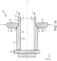
- an apparatus 100 for backward flow forming comprising a mandrel 104 and a headstock 106 at a proximate end of mandrel 104.
- a preform 102 is mounted on mandrel 104 and rotates with mandrel 104 about axis A-A.
- One or more rollers 108 apply a compressive force F to preform 102 and roll circumferentially along the surface of preform 102 in response to the rotation of mandrel 104.
- a mandrel such as mandrel 104 may have a generally cylindrical geometry or may comprise a complex geometry having a curves, multi-radial curves, or steps and, in this regard, the circumference of a mandrel such as mandrel 104 may vary with respect to a position along axis A-A.
- plastic deformation zones 112 are formed in the preform 102 between the rollers 108 and the mandrel 104. Plastic deformation zones 112 advance along the preform 102 in response to rollers 108 advancing toward headstock 106 as shown by arrows 110.
- a work piece 114 flows axially (along the positive x-axis) behind the rollers 108 along the surface 120 of mandrel 104 toward a distal end of mandrel 104.
- work piece 114 continues to flow along and away from mandrel 104 as shown by arrows 116.
- coupling features 118 such as, for example, flats, a flange or holes bored through the work piece, may be formed proximate traveling end 122 of work piece 114.
- coupling features 118 may be formed in response to traveling end 122 departing the mandrel 104.
- a preform such as preform 102 may comprise pre-machined coupling features (i.e. coupling features machined prior to flow forming) which may be excised and discarded from the traveling end of the work piece subsequent to the backward flow forming of the preform.
- pre-machined coupling features i.e. coupling features machined prior to flow forming
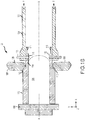
- apparatus 100 for backward flow forming is illustrated with catcher 124 removably coupled at coupling features 118 to work piece 114 by locking pins 126.
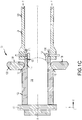
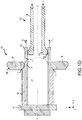
- catcher 124 comprise and be coupled by clamps 127 as shown in FIG. 1C , grabbers 130 having a grabbing surface 132 as shown in FIG. ID, or other such suitable coupling mechanism.
- clamps 127 and grabbers 130 may be mechanically, electro-mechanically, or hydraulically actuated tending thereby to apply a coupling force between clamps 127 or grabbers 130 and traveling end 122.
- grabbing surface 132 may comprise hardened metallic grip enhancing features such as points, cones, pyramids, ridges, teeth, or other suitable feature tending to bite into the material of traveling end 122 and, in that regard, tending to enhance the coupling between catcher 124 and work piece 114.
- catcher 124 When coupled to work piece 114, catcher 124 is coaxial to mandrel 104 and rotates synchronously with work piece 114 and mandrel 104 about axis A-A. Catcher 124 travels (along x-axis) with flow 116 of work piece 114 and tends to support work piece 114 as traveling end 122 moves away from mandrel 104.
- apparatus 100 may comprise sensors 128 which may be configured to transmit measured characteristics of apparatus 100 to a controller 202 ( FIG. 2 described below), thereby providing sensor feedback about apparatus 100.
- the measured characteristics may comprise one of a tension parameter, a deflection parameter, a catcher parameter, or an apparatus parameter.
- the sensor feedback may be, for example position feedback, temperature feedback, pressure feedback, shaft speed, or other data.
- controller 202 may determine a tension T between the work piece 114 and the catcher 124.
- the tension T may be a function of a total required deformation ratio and a material property of the material.
- catcher 124 may be configured to oscillate rotationally with respect to the rotational axis and tending thereby to cause traveling end 122 of work piece 114 to deflect relative to axis A-A.
- work piece 114 tends to have a higher strength than the material at plastic deformation zones 112 and tends to transfer the oscillations into the plastic deformation zones 112.
- the oscillation of catcher 124 may tend to trigger a plastic deformation in a localized zone of shear bands tending thereby to reduce material stresses in the plastic deformation zones and, in response, tending to improve material formability, tending to increase material microstructure homogeneity through the material thickness, and tending to reduce material susceptibility to cracking.
- compressive force F at rollers 108 may tend to be reduced in proportion to the improvement in material formability tending thereby to increase an operational life of rollers 108.
- the oscillations may be about 10° off axis A-A (i.e. a deflection as an absolute value) where the term "about” in this context means ⁇ 5°.
- mandrel 104 may be heated.
- preform 102 may be preheated prior to backward flow forming.
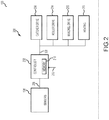
- a schematic diagram of a control system 200 for backward flow forming of shafts may comprise components of apparatus 100.
- Control system 200 may comprise controller 202 in communication with sensors 128 and catcher drive system 204.
- controller 202 may be in communication with roller drive system 214, mandrel drive system 216, and heating system 218.
- Systems in communication with controller 202 may receive commands 208 or signals from controller 202 such as to begin an oscillation, to adjust a tension, to alter an oscillation angle, to heat a component, or to alter a speed.
- controller 202 may comprise a processor.
- controller 202 may be implemented in a single processor or one or more processors configured to implement various logical operations in response to execution of instructions, for example, instructions stored on a non-transitory, tangible, computer-readable medium such as, for example, memory 210 which may store data used, for example, for trending and analysis/prognosis purposes.
- the one or more processors can be a general purpose processor, a microprocessor, a microcontroller, a digital signal processor (DSP), an application specific integrated circuit (ASIC), a field programmable gate array (FPGA) or other programmable logic device, discrete gate or transistor logic, discrete hardware components, or any combination thereof.
- controller 202 may receive and interpret off board data 212 which may comprise configuration data, prerecorded data, external commands, or any other data. In various embodiments, controller 202 may receive and interpret data from one or more sensors 128 located throughout apparatus 100. In various embodiments, controller 202 may receive and interpret sensor data to determine the tension T between the work piece 114 and the catcher 124 and, in response, command catcher drive system 204 to adjust a catcher position tending thereby to alter tension T. In various embodiments, controller 202 may dynamically adjust the catcher position to maintain a constant tension.
- off board data 212 may comprise an external command of the form "start flow forming" or "stop flow forming” and controller 202 may command one of the catcher drive system 204, the roller drive system 214, or the mandrel drive system 216 in response to the external command.
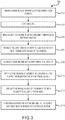
- Method 300 includes mounting the material in an apparatus for backward flow forming (step 302).
- method 300 may include heating a mandrel (step 304).
- Method 300 includes applying a load to a plurality of rollers and forming a plastic deformation zone in the material between the plurality of rollers and the mandrel (step 306).
- Method 300 includes advancing the plurality of rollers toward a headstock at a proximate end of the mandrel (step 306), wherein a work piece flows from the plastic deformation zone between the plurality of rollers and the mandrel toward a distal end of the mandrel.
- Method 300 includes coupling the work piece to a catcher at a traveling end of the work piece (step 308).
- step 308 may further comprise machining a coupling feature in the work piece proximate the traveling end of the work piece.
- Method 300 includes applying a tension defined between the catcher and the plastic deformation zone at the traveling end of the work piece (step 310).
- Method 300 includes deflecting the traveling end of the work piece with respect to an axis of the mandrel (step 312).
- Method 300 includes forming shear banding within the material at the plastic deformation zone in response to the deflection (step 314).
Landscapes
- Engineering & Computer Science (AREA)
- Mechanical Engineering (AREA)
- Shaping Metal By Deep-Drawing, Or The Like (AREA)
Claims (12)
- Einrichtung (100) zum Rückwärtsfließformen eines Materials, umfassend:einen Dorn (104), aufweisend einen Spindelstock (106) an einem proximalen Ende des Dorns (104), wobei der Dorn (104) konfiguriert ist, um sich um eine Achse (A-A) zu drehen;eine Vielzahl von Walzen (108), die radial außerhalb des Dorns (104) angeordnet und konfiguriert sind, um eine Kraft auf das Material auszuüben, um in einer Zone (112) der plastischen Verformung ein Werkstück (114) zu formen, wobei das Werkstück (114) von der Zone (112) der plastischen Verformung zwischen der Vielzahl von Walzen (108) und dem Dorn (104) zu einem distalen Ende des Dorns (104) fließt; undeine Auffangvorrichtung (124) koaxial zum Dorn (104) und an einem Bewegungsende (122) des Werkstücks (114) abnehmbar an das Werkstück (114) gekoppelt,wobei die Auffangvorrichtung (124) konfiguriert ist, um sich mit dem Bewegungsende (122) des Werkstücks (114) zu bewegen, dadurch gekennzeichnet, dass die Auffangvorrichtung (124) eine Spannung in dem Werkstück (114) ausübt.
- Einrichtung (100) nach Anspruch 1, wobei das Bewegungsende (122) ferner ein Kopplungsmerkmal (118) umfasst.
- Einrichtung (100) nach Anspruch 1 oder 2, wobei die Vielzahl von Walzen (108) konfiguriert ist, um sich von dem distalen Ende des Dorns (104) zu dem Spindelstock (106) zu bewegen.
- Einrichtung (100) nach Anspruch 1, 2 oder 3, wobei die Auffangvorrichtung (124) konfiguriert ist, um das Bewegungsende (122) des Werkstücks (114) in Bezug auf die Achse (A-A) des Dorns (104) abzulenken, indem eine Schwingung in Bezug auf die Achse (A-A) des Dorns (104) ausgeführt wird.
- Einrichtung (100) nach einem vorhergehenden Anspruch, wobei die Auffangvorrichtung (124) eines von einem Greifer (130) oder einer Klammer (127) umfasst.
- Einrichtung (100) nach einem vorhergehenden Anspruch, wobei der Dorn (104) eine komplexe Geometrie umfasst, die Kurven, multiradiale Kurven oder Stufen aufweist.
- Verfahren zum Verbessern des Rückwärtsfließformens eines Materials, umfassend:Montieren des Materials in einer Einrichtung (100) zum Rückwärtsfließformen und Anwenden einer Last auf eine Vielzahl von Walzen (108), wobei eine Zone (112) der plastischen Verformung in dem Material zwischen der Vielzahl von Walzen (108) und einem Dorn (104) gebildet wird;Vorrücken der Vielzahl von Walzen (108) zu einem Spindelstock (106) an einem proximalen Ende des Dorns (104), wodurch ein Werkstück (114) geformt wird, wobei das Werkstück (114) von der Zone (112) der plastischen Verformung zwischen der Vielzahl von Walzen (108) und dem Dorn (104) zu einem distalen Ende des Dorns (104) fließt; undKoppeln des Werkstücks (114) an eine Auffangvorrichtung (124) an einem Bewegungsende (122) des Werkstücks (114),dadurch gekennzeichnet, dass das Verfahren ferner Folgendes umfasstAnwenden einer Spannung, die zwischen der Auffangvorrichtung (124) und der Zone (112) der plastischen Verformung definiert ist, an dem Bewegungsende (122) des Werkstücks (114).
- Verfahren nach Anspruch 7, ferner umfassend das maschinelle Bearbeiten eines Kopplungsmerkmals (118) in dem Werkstück (114) in der Nähe des Bewegungsendes (122) des Werkstücks (114).
- Verfahren nach Anspruch 7 oder 8, wobei das Koppeln das Festklammern des Werkstücks (114) an der Auffangvorrichtung (124) umfasst.
- Verfahren nach Anspruch 9, ferner umfassend das Ablenken von einem des Bewegungsendes (122) des Werkstücks (114) in Bezug auf eine Achse (A-A) des Dorns (104).
- Verfahren nach Anspruch 10, wobei die Ablenkung in Bezug auf die Achse (A-A) des Dorns (104) 5° bis 15° beträgt.
- Verfahren nach Anspruch 10 oder 11, ferner umfassend eine Scherbänderung innerhalb des Materials in der Zone (112) der plastischen Verformung als Reaktion auf die Ablenkung.
Applications Claiming Priority (1)
| Application Number | Priority Date | Filing Date | Title |
|---|---|---|---|
| US15/934,500 US11185905B2 (en) | 2018-03-23 | 2018-03-23 | Systems and methods for improving backward flow forming of shafts |
Publications (2)
| Publication Number | Publication Date |
|---|---|
| EP3542918A1 EP3542918A1 (de) | 2019-09-25 |
| EP3542918B1 true EP3542918B1 (de) | 2021-08-25 |
Family
ID=65904107
Family Applications (1)
| Application Number | Title | Priority Date | Filing Date |
|---|---|---|---|
| EP19164061.4A Active EP3542918B1 (de) | 2018-03-23 | 2019-03-20 | Vorrichtung und verfahren zur verbesserung der rückwärtsfliessung von wellen |
Country Status (2)
| Country | Link |
|---|---|
| US (3) | US11185905B2 (de) |
| EP (1) | EP3542918B1 (de) |
Families Citing this family (4)
| Publication number | Priority date | Publication date | Assignee | Title |
|---|---|---|---|---|
| US11185905B2 (en) * | 2018-03-23 | 2021-11-30 | Raytheon Technologies Corporation | Systems and methods for improving backward flow forming of shafts |
| CN112536404A (zh) * | 2019-10-29 | 2021-03-23 | 北京机电研究所有限公司 | 一种空心火车车轴辊锻成型的方法 |
| CN113118285A (zh) * | 2021-04-08 | 2021-07-16 | 内蒙古航天红岗机械有限公司 | 一种发动机壳体反旋毛坯定位工装 |
| IT202200004430A1 (it) * | 2022-03-09 | 2023-09-09 | Univ Degli Studi Padova | Attrezzatura per la fluo-formatura di manufatti, da installare in una macchina particolarmente del tipo provvisto di mezzi con cui portare in rotazione un manufatto da lavorare e procedimento per la fluo-formatura di manufatti |
Family Cites Families (11)
| Publication number | Priority date | Publication date | Assignee | Title |
|---|---|---|---|---|
| US2942337A (en) * | 1954-05-28 | 1960-06-28 | Buderus Eisenwerk | Process for the treatment of thickwalled metallic hollow bodies |
| DE2230554B2 (de) | 1972-06-22 | 1974-08-22 | Leifeld & Co, 4730 Ahlen | Verfahren zur Herstellung eines Anlenkgehäuses für einen Drehfederstab durch Drücken aus einem rohrförmigen Körper |
| DE2252091A1 (de) | 1972-10-24 | 1974-05-02 | Benteler Werke Ag | Rohrfoermiges lagergehaeuse, insbesondere fuer die aufnahme von drehstabfedern |
| US7762114B2 (en) | 2005-09-09 | 2010-07-27 | Applied Materials, Inc. | Flow-formed chamber component having a textured surface |
| DE102006001064B4 (de) * | 2006-01-07 | 2010-12-16 | Sms Meer Gmbh | Verfahren zur Herstellung eines nahtlosen Rohres |
| US20100236122A1 (en) | 2006-07-26 | 2010-09-23 | Fonte Matthew V | Flowforming Gun Barrels and Similar Tubular Devices |
| US9291057B2 (en) | 2012-07-18 | 2016-03-22 | United Technologies Corporation | Tie shaft for gas turbine engine and flow forming method for manufacturing same |
| GB201316829D0 (en) | 2013-09-23 | 2013-11-06 | Rolls Royce Plc | Flow Forming method |
| MX2017000077A (es) | 2014-06-27 | 2017-05-30 | Ati Properties Llc | Tubos de aleacion resistentes a la corrosion de formacion por flujo y tubo manufacturado por los mismos. |
| DE102015109433A1 (de) | 2015-06-12 | 2016-12-15 | WF Maschinenbau und Blechformtechnik GmbH & Co. KG | Verfahren und Vorrichtung zur Wandverformung eines rohrförmigen Werkstücks |
| US11185905B2 (en) * | 2018-03-23 | 2021-11-30 | Raytheon Technologies Corporation | Systems and methods for improving backward flow forming of shafts |
-
2018
- 2018-03-23 US US15/934,500 patent/US11185905B2/en active Active
-
2019
- 2019-03-20 EP EP19164061.4A patent/EP3542918B1/de active Active
-
2021
- 2021-10-28 US US17/513,720 patent/US12194522B2/en active Active
-
2024
- 2024-12-12 US US18/979,214 patent/US20250108425A1/en active Pending
Non-Patent Citations (1)
| Title |
|---|
| None * |
Also Published As
| Publication number | Publication date |
|---|---|
| US11185905B2 (en) | 2021-11-30 |
| US12194522B2 (en) | 2025-01-14 |
| US20220048089A1 (en) | 2022-02-17 |
| US20250108425A1 (en) | 2025-04-03 |
| EP3542918A1 (de) | 2019-09-25 |
| US20190291167A1 (en) | 2019-09-26 |
Similar Documents
| Publication | Publication Date | Title |
|---|---|---|
| US12194522B2 (en) | Systems and methods for improving backward flow forming of shafts | |
| KR101753445B1 (ko) | 마찰 용접에 의한 알루미늄 합금 프로펠러 샤프트 제조 방법 | |
| EP1857195B1 (de) | Verfahren zum Biegen von Metallmaterial und gebogenes Produkt | |
| KR101696224B1 (ko) | 아이어닝 롤러 스피닝을 위한 방법 및 장치 | |
| EP2433722B1 (de) | Biegevorrichtung | |
| US11135642B2 (en) | Method for manufacturing ring-rolled product | |
| US20090288464A1 (en) | Method for producing workpieces | |
| US11298765B2 (en) | Toothed rack and method for producing a toothed rack for a steering gear of a motor vehicle | |
| US3738139A (en) | Metal working | |
| JP2013066903A (ja) | 中空状動力伝達シャフト | |
| EP1946861B1 (de) | Verschlussvorrichtung und Verschlussverfahren | |
| JP2017185540A (ja) | 管体のねじ切り法 | |
| KR102005168B1 (ko) | 다층 헤비-듀티 파이프 제조 동안 클래딩 층을 도포하기 위한 방법 및 코팅 장치 | |
| CN114713751A (zh) | 一种半空心电机轴的挤压和旋锻复合成型工艺 | |
| US10926788B2 (en) | Method for producing a toothed rack for a motor vehicle | |
| KR20150102740A (ko) | 표면 가공 부품의 제조 방법 및 표면 가공 부품의 제조 장치 | |
| JP5958967B2 (ja) | 筒状素材の成形方法 | |
| JP6956649B2 (ja) | 加工方法および加工装置 | |
| CN109354393B (zh) | 一种用于收缩扩张式玻璃微喷管的成型加工装置 | |
| US20210220901A1 (en) | Method for manufacturing steering shaft of steering device | |
| JP5461990B2 (ja) | 中空部材の成形方法 | |
| WO2014119120A1 (ja) | 鍛造装置および鍛造方法 | |
| KR20200089918A (ko) | 차량용 중공 샤프트의 기계식 성형방법 | |
| JPH04105720A (ja) | クラウンローラの製造方法 | |
| CN107218780A (zh) | 一种滚筒类干燥设备旋转筒体与旋转接头之间的连接结构 |
Legal Events
| Date | Code | Title | Description |
|---|---|---|---|
| PUAI | Public reference made under article 153(3) epc to a published international application that has entered the european phase |
Free format text: ORIGINAL CODE: 0009012 |
|
| STAA | Information on the status of an ep patent application or granted ep patent |
Free format text: STATUS: THE APPLICATION HAS BEEN PUBLISHED |
|
| AK | Designated contracting states |
Kind code of ref document: A1 Designated state(s): AL AT BE BG CH CY CZ DE DK EE ES FI FR GB GR HR HU IE IS IT LI LT LU LV MC MK MT NL NO PL PT RO RS SE SI SK SM TR |
|
| AX | Request for extension of the european patent |
Extension state: BA ME |
|
| STAA | Information on the status of an ep patent application or granted ep patent |
Free format text: STATUS: REQUEST FOR EXAMINATION WAS MADE |
|
| 17P | Request for examination filed |
Effective date: 20200325 |
|
| RBV | Designated contracting states (corrected) |
Designated state(s): AL AT BE BG CH CY CZ DE DK EE ES FI FR GB GR HR HU IE IS IT LI LT LU LV MC MK MT NL NO PL PT RO RS SE SI SK SM TR |
|
| STAA | Information on the status of an ep patent application or granted ep patent |
Free format text: STATUS: EXAMINATION IS IN PROGRESS |
|
| 17Q | First examination report despatched |
Effective date: 20200622 |
|
| GRAP | Despatch of communication of intention to grant a patent |
Free format text: ORIGINAL CODE: EPIDOSNIGR1 |
|
| STAA | Information on the status of an ep patent application or granted ep patent |
Free format text: STATUS: GRANT OF PATENT IS INTENDED |
|
| RAP1 | Party data changed (applicant data changed or rights of an application transferred) |
Owner name: RAYTHEON TECHNOLOGIES CORPORATION |
|
| INTG | Intention to grant announced |
Effective date: 20210310 |
|
| GRAS | Grant fee paid |
Free format text: ORIGINAL CODE: EPIDOSNIGR3 |
|
| GRAA | (expected) grant |
Free format text: ORIGINAL CODE: 0009210 |
|
| STAA | Information on the status of an ep patent application or granted ep patent |
Free format text: STATUS: THE PATENT HAS BEEN GRANTED |
|
| AK | Designated contracting states |
Kind code of ref document: B1 Designated state(s): AL AT BE BG CH CY CZ DE DK EE ES FI FR GB GR HR HU IE IS IT LI LT LU LV MC MK MT NL NO PL PT RO RS SE SI SK SM TR |
|
| REG | Reference to a national code |
Ref country code: CH Ref legal event code: EP |
|
| REG | Reference to a national code |
Ref country code: IE Ref legal event code: FG4D Ref country code: AT Ref legal event code: REF Ref document number: 1423263 Country of ref document: AT Kind code of ref document: T Effective date: 20210915 |
|
| REG | Reference to a national code |
Ref country code: DE Ref legal event code: R096 Ref document number: 602019007057 Country of ref document: DE |
|
| REG | Reference to a national code |
Ref country code: LT Ref legal event code: MG9D |
|
| REG | Reference to a national code |
Ref country code: NL Ref legal event code: MP Effective date: 20210825 |
|
| REG | Reference to a national code |
Ref country code: AT Ref legal event code: MK05 Ref document number: 1423263 Country of ref document: AT Kind code of ref document: T Effective date: 20210825 |
|
| PG25 | Lapsed in a contracting state [announced via postgrant information from national office to epo] |
Ref country code: ES Free format text: LAPSE BECAUSE OF FAILURE TO SUBMIT A TRANSLATION OF THE DESCRIPTION OR TO PAY THE FEE WITHIN THE PRESCRIBED TIME-LIMIT Effective date: 20210825 Ref country code: FI Free format text: LAPSE BECAUSE OF FAILURE TO SUBMIT A TRANSLATION OF THE DESCRIPTION OR TO PAY THE FEE WITHIN THE PRESCRIBED TIME-LIMIT Effective date: 20210825 Ref country code: SE Free format text: LAPSE BECAUSE OF FAILURE TO SUBMIT A TRANSLATION OF THE DESCRIPTION OR TO PAY THE FEE WITHIN THE PRESCRIBED TIME-LIMIT Effective date: 20210825 Ref country code: RS Free format text: LAPSE BECAUSE OF FAILURE TO SUBMIT A TRANSLATION OF THE DESCRIPTION OR TO PAY THE FEE WITHIN THE PRESCRIBED TIME-LIMIT Effective date: 20210825 Ref country code: HR Free format text: LAPSE BECAUSE OF FAILURE TO SUBMIT A TRANSLATION OF THE DESCRIPTION OR TO PAY THE FEE WITHIN THE PRESCRIBED TIME-LIMIT Effective date: 20210825 Ref country code: PT Free format text: LAPSE BECAUSE OF FAILURE TO SUBMIT A TRANSLATION OF THE DESCRIPTION OR TO PAY THE FEE WITHIN THE PRESCRIBED TIME-LIMIT Effective date: 20211227 Ref country code: NO Free format text: LAPSE BECAUSE OF FAILURE TO SUBMIT A TRANSLATION OF THE DESCRIPTION OR TO PAY THE FEE WITHIN THE PRESCRIBED TIME-LIMIT Effective date: 20211125 Ref country code: LT Free format text: LAPSE BECAUSE OF FAILURE TO SUBMIT A TRANSLATION OF THE DESCRIPTION OR TO PAY THE FEE WITHIN THE PRESCRIBED TIME-LIMIT Effective date: 20210825 Ref country code: AT Free format text: LAPSE BECAUSE OF FAILURE TO SUBMIT A TRANSLATION OF THE DESCRIPTION OR TO PAY THE FEE WITHIN THE PRESCRIBED TIME-LIMIT Effective date: 20210825 Ref country code: BG Free format text: LAPSE BECAUSE OF FAILURE TO SUBMIT A TRANSLATION OF THE DESCRIPTION OR TO PAY THE FEE WITHIN THE PRESCRIBED TIME-LIMIT Effective date: 20211125 |
|
| PG25 | Lapsed in a contracting state [announced via postgrant information from national office to epo] |
Ref country code: PL Free format text: LAPSE BECAUSE OF FAILURE TO SUBMIT A TRANSLATION OF THE DESCRIPTION OR TO PAY THE FEE WITHIN THE PRESCRIBED TIME-LIMIT Effective date: 20210825 Ref country code: LV Free format text: LAPSE BECAUSE OF FAILURE TO SUBMIT A TRANSLATION OF THE DESCRIPTION OR TO PAY THE FEE WITHIN THE PRESCRIBED TIME-LIMIT Effective date: 20210825 Ref country code: GR Free format text: LAPSE BECAUSE OF FAILURE TO SUBMIT A TRANSLATION OF THE DESCRIPTION OR TO PAY THE FEE WITHIN THE PRESCRIBED TIME-LIMIT Effective date: 20211126 |
|
| PG25 | Lapsed in a contracting state [announced via postgrant information from national office to epo] |
Ref country code: NL Free format text: LAPSE BECAUSE OF FAILURE TO SUBMIT A TRANSLATION OF THE DESCRIPTION OR TO PAY THE FEE WITHIN THE PRESCRIBED TIME-LIMIT Effective date: 20210825 |
|
| PG25 | Lapsed in a contracting state [announced via postgrant information from national office to epo] |
Ref country code: DK Free format text: LAPSE BECAUSE OF FAILURE TO SUBMIT A TRANSLATION OF THE DESCRIPTION OR TO PAY THE FEE WITHIN THE PRESCRIBED TIME-LIMIT Effective date: 20210825 |
|
| REG | Reference to a national code |
Ref country code: DE Ref legal event code: R097 Ref document number: 602019007057 Country of ref document: DE |
|
| PG25 | Lapsed in a contracting state [announced via postgrant information from national office to epo] |
Ref country code: SM Free format text: LAPSE BECAUSE OF FAILURE TO SUBMIT A TRANSLATION OF THE DESCRIPTION OR TO PAY THE FEE WITHIN THE PRESCRIBED TIME-LIMIT Effective date: 20210825 Ref country code: SK Free format text: LAPSE BECAUSE OF FAILURE TO SUBMIT A TRANSLATION OF THE DESCRIPTION OR TO PAY THE FEE WITHIN THE PRESCRIBED TIME-LIMIT Effective date: 20210825 Ref country code: RO Free format text: LAPSE BECAUSE OF FAILURE TO SUBMIT A TRANSLATION OF THE DESCRIPTION OR TO PAY THE FEE WITHIN THE PRESCRIBED TIME-LIMIT Effective date: 20210825 Ref country code: EE Free format text: LAPSE BECAUSE OF FAILURE TO SUBMIT A TRANSLATION OF THE DESCRIPTION OR TO PAY THE FEE WITHIN THE PRESCRIBED TIME-LIMIT Effective date: 20210825 Ref country code: CZ Free format text: LAPSE BECAUSE OF FAILURE TO SUBMIT A TRANSLATION OF THE DESCRIPTION OR TO PAY THE FEE WITHIN THE PRESCRIBED TIME-LIMIT Effective date: 20210825 Ref country code: AL Free format text: LAPSE BECAUSE OF FAILURE TO SUBMIT A TRANSLATION OF THE DESCRIPTION OR TO PAY THE FEE WITHIN THE PRESCRIBED TIME-LIMIT Effective date: 20210825 |
|
| PLBE | No opposition filed within time limit |
Free format text: ORIGINAL CODE: 0009261 |
|
| STAA | Information on the status of an ep patent application or granted ep patent |
Free format text: STATUS: NO OPPOSITION FILED WITHIN TIME LIMIT |
|
| PG25 | Lapsed in a contracting state [announced via postgrant information from national office to epo] |
Ref country code: IT Free format text: LAPSE BECAUSE OF FAILURE TO SUBMIT A TRANSLATION OF THE DESCRIPTION OR TO PAY THE FEE WITHIN THE PRESCRIBED TIME-LIMIT Effective date: 20210825 |
|
| 26N | No opposition filed |
Effective date: 20220527 |
|
| PG25 | Lapsed in a contracting state [announced via postgrant information from national office to epo] |
Ref country code: SI Free format text: LAPSE BECAUSE OF FAILURE TO SUBMIT A TRANSLATION OF THE DESCRIPTION OR TO PAY THE FEE WITHIN THE PRESCRIBED TIME-LIMIT Effective date: 20210825 |
|
| PG25 | Lapsed in a contracting state [announced via postgrant information from national office to epo] |
Ref country code: MC Free format text: LAPSE BECAUSE OF FAILURE TO SUBMIT A TRANSLATION OF THE DESCRIPTION OR TO PAY THE FEE WITHIN THE PRESCRIBED TIME-LIMIT Effective date: 20210825 |
|
| REG | Reference to a national code |
Ref country code: CH Ref legal event code: PL |
|
| REG | Reference to a national code |
Ref country code: BE Ref legal event code: MM Effective date: 20220331 |
|
| PG25 | Lapsed in a contracting state [announced via postgrant information from national office to epo] |
Ref country code: LU Free format text: LAPSE BECAUSE OF NON-PAYMENT OF DUE FEES Effective date: 20220320 Ref country code: LI Free format text: LAPSE BECAUSE OF NON-PAYMENT OF DUE FEES Effective date: 20220331 Ref country code: IE Free format text: LAPSE BECAUSE OF NON-PAYMENT OF DUE FEES Effective date: 20220320 Ref country code: CH Free format text: LAPSE BECAUSE OF NON-PAYMENT OF DUE FEES Effective date: 20220331 |
|
| PG25 | Lapsed in a contracting state [announced via postgrant information from national office to epo] |
Ref country code: BE Free format text: LAPSE BECAUSE OF NON-PAYMENT OF DUE FEES Effective date: 20220331 |
|
| P01 | Opt-out of the competence of the unified patent court (upc) registered |
Effective date: 20230521 |
|
| PG25 | Lapsed in a contracting state [announced via postgrant information from national office to epo] |
Ref country code: MK Free format text: LAPSE BECAUSE OF FAILURE TO SUBMIT A TRANSLATION OF THE DESCRIPTION OR TO PAY THE FEE WITHIN THE PRESCRIBED TIME-LIMIT Effective date: 20210825 Ref country code: CY Free format text: LAPSE BECAUSE OF FAILURE TO SUBMIT A TRANSLATION OF THE DESCRIPTION OR TO PAY THE FEE WITHIN THE PRESCRIBED TIME-LIMIT Effective date: 20210825 |
|
| PG25 | Lapsed in a contracting state [announced via postgrant information from national office to epo] |
Ref country code: HU Free format text: LAPSE BECAUSE OF FAILURE TO SUBMIT A TRANSLATION OF THE DESCRIPTION OR TO PAY THE FEE WITHIN THE PRESCRIBED TIME-LIMIT; INVALID AB INITIO Effective date: 20190320 |
|
| PG25 | Lapsed in a contracting state [announced via postgrant information from national office to epo] |
Ref country code: MT Free format text: LAPSE BECAUSE OF FAILURE TO SUBMIT A TRANSLATION OF THE DESCRIPTION OR TO PAY THE FEE WITHIN THE PRESCRIBED TIME-LIMIT Effective date: 20210825 |
|
| PGFP | Annual fee paid to national office [announced via postgrant information from national office to epo] |
Ref country code: DE Payment date: 20250218 Year of fee payment: 7 |
|
| PGFP | Annual fee paid to national office [announced via postgrant information from national office to epo] |
Ref country code: FR Payment date: 20250218 Year of fee payment: 7 |
|
| PGFP | Annual fee paid to national office [announced via postgrant information from national office to epo] |
Ref country code: GB Payment date: 20250221 Year of fee payment: 7 |
|
| REG | Reference to a national code |
Ref country code: DE Ref legal event code: R081 Ref document number: 602019007057 Country of ref document: DE Owner name: RTX CORPORATION (N.D.GES.D. STAATES DELAWARE),, US Free format text: FORMER OWNER: RAYTHEON TECHNOLOGIES CORP., FARMINGTON, CT, US |