EP3542906B1 - Feldspritze mit düsenanordnungen - Google Patents
Feldspritze mit düsenanordnungen Download PDFInfo
- Publication number
- EP3542906B1 EP3542906B1 EP19401013.8A EP19401013A EP3542906B1 EP 3542906 B1 EP3542906 B1 EP 3542906B1 EP 19401013 A EP19401013 A EP 19401013A EP 3542906 B1 EP3542906 B1 EP 3542906B1
- Authority
- EP
- European Patent Office
- Prior art keywords
- spray
- nozzle
- cavity
- field sprayer
- nozzle assemblies
- Prior art date
- Legal status (The legal status is an assumption and is not a legal conclusion. Google has not performed a legal analysis and makes no representation as to the accuracy of the status listed.)
- Active
Links
Images
Classifications
-
- A—HUMAN NECESSITIES
- A01—AGRICULTURE; FORESTRY; ANIMAL HUSBANDRY; HUNTING; TRAPPING; FISHING
- A01M—CATCHING, TRAPPING OR SCARING OF ANIMALS; APPARATUS FOR THE DESTRUCTION OF NOXIOUS ANIMALS OR NOXIOUS PLANTS
- A01M7/00—Special adaptations or arrangements of liquid-spraying apparatus for purposes covered by this subclass
- A01M7/005—Special arrangements or adaptations of the spraying or distributing parts, e.g. adaptations or mounting of the spray booms, mounting of the nozzles, protection shields
- A01M7/006—Mounting of the nozzles
-
- B—PERFORMING OPERATIONS; TRANSPORTING
- B05—SPRAYING OR ATOMISING IN GENERAL; APPLYING FLUENT MATERIALS TO SURFACES, IN GENERAL
- B05B—SPRAYING APPARATUS; ATOMISING APPARATUS; NOZZLES
- B05B1/00—Nozzles, spray heads or other outlets, with or without auxiliary devices such as valves, heating means
- B05B1/02—Nozzles, spray heads or other outlets, with or without auxiliary devices such as valves, heating means designed to produce a jet, spray, or other discharge of particular shape or nature, e.g. in single drops, or having an outlet of particular shape
- B05B1/08—Nozzles, spray heads or other outlets, with or without auxiliary devices such as valves, heating means designed to produce a jet, spray, or other discharge of particular shape or nature, e.g. in single drops, or having an outlet of particular shape of pulsating nature, e.g. delivering liquid in successive separate quantities
- B05B1/083—Nozzles, spray heads or other outlets, with or without auxiliary devices such as valves, heating means designed to produce a jet, spray, or other discharge of particular shape or nature, e.g. in single drops, or having an outlet of particular shape of pulsating nature, e.g. delivering liquid in successive separate quantities the pulsating mechanism comprising movable parts
-
- B—PERFORMING OPERATIONS; TRANSPORTING
- B05—SPRAYING OR ATOMISING IN GENERAL; APPLYING FLUENT MATERIALS TO SURFACES, IN GENERAL
- B05B—SPRAYING APPARATUS; ATOMISING APPARATUS; NOZZLES
- B05B1/00—Nozzles, spray heads or other outlets, with or without auxiliary devices such as valves, heating means
- B05B1/14—Nozzles, spray heads or other outlets, with or without auxiliary devices such as valves, heating means with multiple outlet openings; with strainers in or outside the outlet opening
- B05B1/16—Nozzles, spray heads or other outlets, with or without auxiliary devices such as valves, heating means with multiple outlet openings; with strainers in or outside the outlet opening having selectively- effective outlets
- B05B1/1627—Nozzles, spray heads or other outlets, with or without auxiliary devices such as valves, heating means with multiple outlet openings; with strainers in or outside the outlet opening having selectively- effective outlets with a selecting mechanism comprising a gate valve, a sliding valve or a cock
- B05B1/1636—Nozzles, spray heads or other outlets, with or without auxiliary devices such as valves, heating means with multiple outlet openings; with strainers in or outside the outlet opening having selectively- effective outlets with a selecting mechanism comprising a gate valve, a sliding valve or a cock by relative rotative movement of the valve elements
- B05B1/1645—Nozzles, spray heads or other outlets, with or without auxiliary devices such as valves, heating means with multiple outlet openings; with strainers in or outside the outlet opening having selectively- effective outlets with a selecting mechanism comprising a gate valve, a sliding valve or a cock by relative rotative movement of the valve elements the outlets being rotated during selection
- B05B1/1654—Nozzles, spray heads or other outlets, with or without auxiliary devices such as valves, heating means with multiple outlet openings; with strainers in or outside the outlet opening having selectively- effective outlets with a selecting mechanism comprising a gate valve, a sliding valve or a cock by relative rotative movement of the valve elements the outlets being rotated during selection about an axis parallel to the liquid passage in the stationary valve element
-
- B—PERFORMING OPERATIONS; TRANSPORTING
- B05—SPRAYING OR ATOMISING IN GENERAL; APPLYING FLUENT MATERIALS TO SURFACES, IN GENERAL
- B05B—SPRAYING APPARATUS; ATOMISING APPARATUS; NOZZLES
- B05B15/00—Details of spraying plant or spraying apparatus not otherwise provided for; Accessories
- B05B15/40—Filters located upstream of the spraying outlets
-
- B—PERFORMING OPERATIONS; TRANSPORTING
- B05—SPRAYING OR ATOMISING IN GENERAL; APPLYING FLUENT MATERIALS TO SURFACES, IN GENERAL
- B05B—SPRAYING APPARATUS; ATOMISING APPARATUS; NOZZLES
- B05B15/00—Details of spraying plant or spraying apparatus not otherwise provided for; Accessories
- B05B15/60—Arrangements for mounting, supporting or holding spraying apparatus
- B05B15/65—Mounting arrangements for fluid connection of the spraying apparatus or its outlets to flow conduits
- B05B15/658—Mounting arrangements for fluid connection of the spraying apparatus or its outlets to flow conduits the spraying apparatus or its outlet axis being perpendicular to the flow conduit
Definitions
- the invention relates to a field sprayer with a distributor linkage and a plurality of nozzle arrangements attached to it according to the preamble of claim 1.
- field sprayers comprise distributor rods which can be folded out transversely to the direction of travel and have a large number of spray nozzles for applying a spray to agricultural areas.
- the spray nozzles are components of nozzle arrangements with centrally switchable valves, which are arranged on the distributor rod at suitable distances from one another and which increasingly work according to the known principle of pulse width modulation for setting the flow rate.
- the individual nozzle arrangements usually have several spray nozzles that can be optionally connected to the valve. It is then customary to arrange a spray medium filter in front of each spray nozzle, which is intended to hold back solids in the spray medium, for example impurities.
- Reducers in the form of stoppers which can be introduced within the nozzle arrangement, in particular between a valve of the nozzle arrangement and a connection for a spray nozzle.
- the disadvantage here is that further cavities remain along the spray medium channel, in particular in the area of the connection and the spray nozzle, which lead to the formation of disruptive air bubbles.
- the reducers described here have a line cross-section that is only slightly restricted to the cavity, so that air bubbles can continue to arise, especially when using pulse-width modulated valves, and thus have a negative effect on the dispensing of spray agent.
- the nozzle arrangement comprises a nozzle assembly with a valve for pulse-width-modulated release of a spray agent and, subsequently, a spray agent channel and at least one connection for a spray nozzle, with a cavity for inserting a spray agent filter subsequently being formed.
- the nozzle arrangement comprises a reducer, which is present in the cavity instead of the spray agent filter, and has a line cross-section for the spray agent that is reduced compared to the cavity.
- the nozzle assembly is located at a junction from a main line for the spray agent running along the distributor rod.
- the control for pulse width modulation of the valve takes place in a known manner centrally from a field sprayer and / or an associated tractor.
- the surface area of the line cross section of the reducer is, in particular on average, 5-50 mm 2 , in particular 10-30 mm 2 . It then runs preferably a suitably sized central channel through the reducer. To determine an average line cross-section, the volume of the duct could be calculated by integration over its length and divided by this.
- the spray then flows so quickly that any air bubbles that may be present are carried along and removed.
- the channel in the reducer can then be viewed as a continuation of the spray agent channel and taken into account when calculating the flow conditions in the nozzle assembly.
- the reducer has an external volume which is at least 50% or at least 75%, and in particular at least 90%, of the volume of the cavity. This enables a particularly effective avoidance of air bubbles between the valve and the connection to the spray nozzle.
- the reducer preferably further comprises a tapered section for narrowing a transition area between the spray medium channel and the cavity.
- the nozzle arrangement preferably further comprises a securing ring, which is fastened to the connection, in particular in a form-fitting manner, and which acts as a stop on the outlet side for the reducer. This prevents the reducer from falling out when assembling / disassembling a spray nozzle.
- the securing ring that can be firmly connected to the reducer can make it easier to remove and / or dismantle the reducer.
- the locking ring can be gripped, for example, by means of a suitable tool and thus the entire reducer can be easily removed from the cavity.
- the reducer can have dismantling elements that facilitate removal and / or dismantling of the reducer.
- dismantling elements for example, eyelets, shoulders or recesses are arranged on the reducer, which are suitable, for example, for engaging tools.
- connection is preferably designed as a receiving socket for the spray nozzle.
- the spray nozzle can then be screwed onto the connection in an ergonomic way, for example by means of a fine thread or a bayonet lock.
- the nozzle arrangement preferably comprises a spray nozzle connected to the connection.
- the spray nozzle is screwed on, for example, and then generates a pulsed spray cone during operation with a pulse width modulated by the valve.
- the nozzle assembly preferably comprises a fixed base element with a section of the spray medium channel and a movably mounted switchover element with cavities for spray medium filters and connections for spray nozzles that can be optionally connected to the section with respect to a distributor rod that carries it. Consequently, spray nozzles with different Spray characteristics can be connected to the valve without assembly work.
- a reducer is then preferably present in each cavity.
- the switching element is preferably designed as a rotary element for receiving at least three spray nozzles. This enables a space-saving design and an ergonomic change between different spray nozzles.
- the rotary element then works, for example, in the manner of a revolver drum with latching positions at which the first section of the spray medium channel is connected to one of the cavities in each case.
- switching elements designed as slides or other switching mechanisms would also be conceivable, provided that a spray medium channel can be defined between the valve and the connection for a spray nozzle connected to it in the above sense.
- the object set is also achieved by a field sprayer with a distributor rod and several nozzle arrangements attached to it according to at least one of the previous embodiments.
- the field sprayer can be self-propelled or pulled by a tractor and controlled centrally in a known manner.
- a preferred embodiment is shown in the drawing.
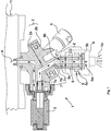
- the single figure shows a nozzle arrangement on the main line of a distributor rod.
- the nozzle arrangement 1 comprises a nozzle assembly 2 with a valve 3 attached to it for the pulse-width-modulated release of a spray medium 4 present on the inlet side of the nozzle assembly 2 under a suitable line pressure. for dispensing the spray 4 in the form of spray cones 4a on an agricultural cultivation area.
- the valve 3 and each one of the connections 5 are connected to one another by a spray medium channel 7 running inside the nozzle assembly 2.
- the spray medium channel 7 is preferably divided into a first section 7a, which runs through a base element 2a of the nozzle assembly 2, which is fixed with respect to an assigned distributor rod of a field sprayer (not shown), and into a second section 7b, which is passed through a switchover element 2b of the nozzle assembly 2 that is movable in relation to it leads to one of the connections 5 each.
- the switchover element 2b is preferably mounted as a rotary element in the sense of a revolver drum or the like so as to be rotatable in / on the base element 2a and has several latching positions on, at which the first section 7a of the spray medium channel 7 is connected to one of the second sections 7b.
- connection 5 comprises a cavity 8 for receiving an outlet-side spray filter (not shown) with a diameter of 12 mm, for example.
- a reducer 9 instead of the spray agent filter on the outlet side, a reducer 9 with a preferably central channel 9a for the spray 4 is located in the cavity 8.
- the locking ring 5b can be firmly connected to the reducer 9.
- the securing ring 5b facilitates the removal and / or dismantling of the reducer 9 in that the securing ring 5b is gripped, for example, by means of a suitable tool.
- the reducer 9 on the securing ring 5b can thus be removed from the cavity 8.
- the reducer 9 can have dismantling elements that facilitate removal and / or dismantling of the reducer 9.
- dismantling elements that facilitate removal and / or dismantling of the reducer 9.
- eyelets, shoulders or recesses can be arranged on the reducer 9, which are suitable, for example, for engaging tools.
- the cavity 8 and the reducer 9 are preferably rotationally symmetrical with respect to their longitudinal axes.
- the reducer 9 takes up, for example, at least 50%, preferably at least 75% and in particular at least 90% of the volume of the cavity 8.
- the cavity 8 is to be understood as an area that is configured to accommodate an outlet-side spray filter, in particular as a cylindrical recess in connection 5.
- the volume of the reducer 9 is then derived from its external dimensions in that section that is inside the cavity 8 in the installed state lies.
- the cavity 8 is indicated in the figure as a corresponding section of the connection 5 between dashed lines.
- the spray medium channel 7 can comprise a transition section 7c that widens from the second section 7b to the adjoining cavity 8.
- a tapered section 9b is then preferably formed on the reducer 9, which protrudes into the transition section 7c of the spray medium channel 7, narrows it and there counteracts the formation and / or adhesion of air bubbles.
- connections 5 are preferably designed as receiving nozzles on which the spray nozzles 6 can be screwed on from below, for example by means of a bayonet lock 5c.
- the receiving nozzles are preferably integral components of the switching element 2b.
- the spray agent filter 10 on the inlet side jointly protects not only the spray nozzles 6 attached to the connections 5 against solids or similar material possibly present in the spray agent 4, but also the valve 3, which has a comparatively filigree structure for pulse width modulation and is therefore fundamentally sensitive to solids in the spray agent 4 is. Nevertheless, the spray agent filter 10 on the inlet side is not absolutely necessary, for example when using suitably prefabricated spray agents 4 without fixed components or components to be filtered out for other reasons.
- the surface area of the line cross section LQ of the channel 9a in the reducer 9 is preferably 5-50 mm 2 , in particular 10-30 mm 2, throughout.
- a central channel 9a with a diameter of 5-6 mm is particularly suitable. Air bubbles can then hardly form therein and, if this cannot be completely avoided, are reliably entrained and flushed out by the spray 4, which flows there comparatively quickly.
- the reducing piece 9 used thus counteracts the formation and adhesion of air bubbles between the valve 3 and the outlet 5a of the connection 5 as a whole. Any other venting of the spray medium channel 7 and / or the cavity 8 is therefore unnecessary.
- the line cross-section LQ in the reducer 9 is preferably round or elliptical.
- other cross-sectional shapes, including lateral channels for the spray 4 that are open to the inner wall of the cavity 8, could in principle be formed in the reducer 9.
- the spray medium channel 7 and the cavity 8 are preferably at most 100 mm long overall in order to limit pressure losses between the valve 3 and the respectively connected spray nozzle 6 to a suitable extent, even with the reducing piece 9 inserted.
- the described subdivision of the nozzle assembly 2 into an inlet-side base element 2a with the valve 3 and a switchover element that is movable and in particular rotatable in relation to it 2b with several and in particular at least three connections 5 is not absolutely necessary.
- the nozzle assembly 2 could in principle also have a single connection 5 for a spray nozzle 6.
- the nozzle assembly 2 then does not have to have a switchover element 2b that is movable with respect to the fixed base element 2a.
- line cross-sections in the area of the spray agent channel 7 and the reducer 9 can vary over their length. If necessary, an average line cross-section LQ for the channel 9a in the reducer 9 must then be calculated by integration and divided by its length. The same applies to the calculation of volumes for the reducer 9 and the cavity 8, see, for example, the different diameters of the reducer 9 in the region of the outlet 5a.
- the reducer 9 can advantageously be produced from a plastic such as, for example, polyoxymethylene (POM), by machining or also by other conventional methods. This favors inexpensive and flexible equipment and, if necessary, retrofitting of nozzle arrangements 1 with reducers 9 and / or with spray agent filters 10 connected upstream of valves 3.
- a plastic such as, for example, polyoxymethylene (POM)
- POM polyoxymethylene
Landscapes
- Life Sciences & Earth Sciences (AREA)
- Engineering & Computer Science (AREA)
- Insects & Arthropods (AREA)
- Pest Control & Pesticides (AREA)
- Wood Science & Technology (AREA)
- Zoology (AREA)
- Environmental Sciences (AREA)
- Catching Or Destruction (AREA)
- Nozzles (AREA)
Priority Applications (1)
| Application Number | Priority Date | Filing Date | Title |
|---|---|---|---|
| PL19401013T PL3542906T3 (pl) | 2018-03-19 | 2019-03-08 | Opryskiwacz polowy z zespołami dysz |
Applications Claiming Priority (1)
| Application Number | Priority Date | Filing Date | Title |
|---|---|---|---|
| DE102018106334.2A DE102018106334A1 (de) | 2018-03-19 | 2018-03-19 | Düsenanordnung für eine Feldspritze |
Publications (2)
| Publication Number | Publication Date |
|---|---|
| EP3542906A1 EP3542906A1 (de) | 2019-09-25 |
| EP3542906B1 true EP3542906B1 (de) | 2021-12-01 |
Family
ID=66103008
Family Applications (1)
| Application Number | Title | Priority Date | Filing Date |
|---|---|---|---|
| EP19401013.8A Active EP3542906B1 (de) | 2018-03-19 | 2019-03-08 | Feldspritze mit düsenanordnungen |
Country Status (4)
| Country | Link |
|---|---|
| EP (1) | EP3542906B1 (pl) |
| DE (1) | DE102018106334A1 (pl) |
| DK (1) | DK3542906T3 (pl) |
| PL (1) | PL3542906T3 (pl) |
Cited By (2)
| Publication number | Priority date | Publication date | Assignee | Title |
|---|---|---|---|---|
| FR3143268A1 (fr) * | 2022-12-19 | 2024-06-21 | Exel Industries | Porte-buses multiple pour un système de pulvérisation agricole |
| WO2024206670A1 (en) * | 2023-03-29 | 2024-10-03 | Spraying Systems Co. | Spray nozzle body for use with on/off liquid supply control |
Families Citing this family (1)
| Publication number | Priority date | Publication date | Assignee | Title |
|---|---|---|---|---|
| DE102020101392B4 (de) | 2020-01-22 | 2021-09-16 | Amazonen-Werke H. Dreyer SE & Co. KG | Düsenanordnung und landwirtschaftliche Feldspritze |
Family Cites Families (5)
| Publication number | Priority date | Publication date | Assignee | Title |
|---|---|---|---|---|
| US4105050A (en) * | 1976-10-20 | 1978-08-08 | Donald W. Hendrickson | Integral flanged elastomeric flow restrictor |
| DE102004056867A1 (de) * | 2004-11-25 | 2006-06-01 | John Deere Fabriek Horst B.V. | Düsenvorrichtung |
| US7502665B2 (en) * | 2005-05-23 | 2009-03-10 | Capstan Ag Systems, Inc. | Networked diagnostic and control system for dispensing apparatus |
| US10444048B2 (en) * | 2014-12-19 | 2019-10-15 | Deere & Company | Fluid flow monitoring system |
| UA125372C2 (uk) * | 2015-04-01 | 2022-03-02 | Спреїнг Системс Ко. | Сільськогосподарський розпилювач для розпилення рідких сільськогосподарських хімікатів регульованим способом, залежним від тиску рідкого сільськогосподарського хімікату |
-
2018
- 2018-03-19 DE DE102018106334.2A patent/DE102018106334A1/de not_active Withdrawn
-
2019
- 2019-03-08 DK DK19401013.8T patent/DK3542906T3/da active
- 2019-03-08 PL PL19401013T patent/PL3542906T3/pl unknown
- 2019-03-08 EP EP19401013.8A patent/EP3542906B1/de active Active
Cited By (3)
| Publication number | Priority date | Publication date | Assignee | Title |
|---|---|---|---|---|
| FR3143268A1 (fr) * | 2022-12-19 | 2024-06-21 | Exel Industries | Porte-buses multiple pour un système de pulvérisation agricole |
| EP4388872A1 (fr) * | 2022-12-19 | 2024-06-26 | Exel Industries | Porte-buses multiple pour un système de pulvérisation agricole |
| WO2024206670A1 (en) * | 2023-03-29 | 2024-10-03 | Spraying Systems Co. | Spray nozzle body for use with on/off liquid supply control |
Also Published As
| Publication number | Publication date |
|---|---|
| DE102018106334A1 (de) | 2019-09-19 |
| EP3542906A1 (de) | 2019-09-25 |
| DK3542906T3 (da) | 2022-01-10 |
| PL3542906T3 (pl) | 2022-01-24 |
Similar Documents
| Publication | Publication Date | Title |
|---|---|---|
| EP3542906B1 (de) | Feldspritze mit düsenanordnungen | |
| EP3226996B1 (de) | Filtervorrichtung, hydrauliksystem und rückspülverfahren | |
| AT407611B (de) | Rückspülvorsatzgerät für eine filtereinrichtung | |
| EP2106236B1 (de) | Korbführungsschiene für eine geschirrspülmaschine | |
| EP3863895A1 (de) | Anbauteil für einen wischerarm | |
| EP3453805B1 (de) | Spülwasserverteiler | |
| EP0540546B1 (de) | Filtriervorrichtung für thermoplastisches kunststoffmaterial | |
| EP1737640B1 (de) | Rückspülbare filtervorrichtung | |
| EP3543412B1 (de) | Spülverteilersystem für sanitärartikel und sanitärartikel mit einem solchen spülverteilersystem | |
| EP3533523B1 (de) | Düsenanordnung für eine feldspritze | |
| DE10151496B4 (de) | Filtereinrichtung mit Filterrotor, speziellen Filterelementen und permanenter Rückspülung der Filterelemente sowie einer Spülschmelzeregulierung mittels Spülventil | |
| EP1161293B1 (de) | Reinigungsvorrichtung | |
| DE60217792T2 (de) | Düse | |
| CH714828A2 (de) | Toilette. | |
| DE4105867C2 (de) | Filtereinrichtung für flüssigen Kunststoff führende Druckleitungen | |
| EP3647504B1 (de) | Sanitärartikelanordnung | |
| EP3812123A1 (de) | Kalibriervorrichtung für den einsatz in einer extrudieranlage für kunststoffrohre und extrudieranlage | |
| WO2014184220A1 (de) | Schmelzefilter mit einer antriebsvorrichtung zur aktiven vorflutung | |
| EP4621147A1 (de) | Wc mit ringspülung | |
| EP3919792B1 (de) | Ventilkörper | |
| EP3719225B1 (de) | Abgabevorrichtung zur abgabe von reinigungsmittel | |
| DE10206210C1 (de) | Vorrichtung zum Entfernen von an Oberflächen anhaftenden Partikeln mittels eines befeuchteten Wischelements | |
| DE102024105325A1 (de) | Bernoulli-Filter-Vorrichtung und Verfahren zum Reinigen einer Bernoulli-Filter-Vorrichtung | |
| DE2847752C3 (de) | Vorrichtung zur Behandlung von Formoberflächen durch Besprühen mit einem oder mehreren Sprüh- und Blasköpfen | |
| CH715567B1 (de) | Spülventil. |
Legal Events
| Date | Code | Title | Description |
|---|---|---|---|
| PUAI | Public reference made under article 153(3) epc to a published international application that has entered the european phase |
Free format text: ORIGINAL CODE: 0009012 |
|
| STAA | Information on the status of an ep patent application or granted ep patent |
Free format text: STATUS: THE APPLICATION HAS BEEN PUBLISHED |
|
| AK | Designated contracting states |
Kind code of ref document: A1 Designated state(s): AL AT BE BG CH CY CZ DE DK EE ES FI FR GB GR HR HU IE IS IT LI LT LU LV MC MK MT NL NO PL PT RO RS SE SI SK SM TR |
|
| AX | Request for extension of the european patent |
Extension state: BA ME |
|
| STAA | Information on the status of an ep patent application or granted ep patent |
Free format text: STATUS: REQUEST FOR EXAMINATION WAS MADE |
|
| 17P | Request for examination filed |
Effective date: 20200302 |
|
| RBV | Designated contracting states (corrected) |
Designated state(s): AL AT BE BG CH CY CZ DE DK EE ES FI FR GB GR HR HU IE IS IT LI LT LU LV MC MK MT NL NO PL PT RO RS SE SI SK SM TR |
|
| RAP3 | Party data changed (applicant data changed or rights of an application transferred) |
Owner name: AMAZONEN-WERK H. DREYER SE & CO. KG Owner name: ROMETRON B.V. |
|
| RAP3 | Party data changed (applicant data changed or rights of an application transferred) |
Owner name: AMAZONEN-WERKE H. DREYER SE & CO. KG Owner name: ROMETRON B.V. |
|
| GRAP | Despatch of communication of intention to grant a patent |
Free format text: ORIGINAL CODE: EPIDOSNIGR1 |
|
| STAA | Information on the status of an ep patent application or granted ep patent |
Free format text: STATUS: GRANT OF PATENT IS INTENDED |
|
| INTG | Intention to grant announced |
Effective date: 20210809 |
|
| GRAS | Grant fee paid |
Free format text: ORIGINAL CODE: EPIDOSNIGR3 |
|
| GRAA | (expected) grant |
Free format text: ORIGINAL CODE: 0009210 |
|
| STAA | Information on the status of an ep patent application or granted ep patent |
Free format text: STATUS: THE PATENT HAS BEEN GRANTED |
|
| AK | Designated contracting states |
Kind code of ref document: B1 Designated state(s): AL AT BE BG CH CY CZ DE DK EE ES FI FR GB GR HR HU IE IS IT LI LT LU LV MC MK MT NL NO PL PT RO RS SE SI SK SM TR |
|
| REG | Reference to a national code |
Ref country code: GB Ref legal event code: FG4D Free format text: NOT ENGLISH |
|
| REG | Reference to a national code |
Ref country code: AT Ref legal event code: REF Ref document number: 1451261 Country of ref document: AT Kind code of ref document: T Effective date: 20211215 Ref country code: CH Ref legal event code: EP |
|
| REG | Reference to a national code |
Ref country code: IE Ref legal event code: FG4D Free format text: LANGUAGE OF EP DOCUMENT: GERMAN |
|
| REG | Reference to a national code |
Ref country code: DE Ref legal event code: R096 Ref document number: 502019002916 Country of ref document: DE |
|
| REG | Reference to a national code |
Ref country code: DK Ref legal event code: T3 Effective date: 20220106 |
|
| REG | Reference to a national code |
Ref country code: NL Ref legal event code: FP |
|
| REG | Reference to a national code |
Ref country code: LT Ref legal event code: MG9D |
|
| PG25 | Lapsed in a contracting state [announced via postgrant information from national office to epo] |
Ref country code: RS Free format text: LAPSE BECAUSE OF FAILURE TO SUBMIT A TRANSLATION OF THE DESCRIPTION OR TO PAY THE FEE WITHIN THE PRESCRIBED TIME-LIMIT Effective date: 20211201 Ref country code: LT Free format text: LAPSE BECAUSE OF FAILURE TO SUBMIT A TRANSLATION OF THE DESCRIPTION OR TO PAY THE FEE WITHIN THE PRESCRIBED TIME-LIMIT Effective date: 20211201 Ref country code: FI Free format text: LAPSE BECAUSE OF FAILURE TO SUBMIT A TRANSLATION OF THE DESCRIPTION OR TO PAY THE FEE WITHIN THE PRESCRIBED TIME-LIMIT Effective date: 20211201 Ref country code: BG Free format text: LAPSE BECAUSE OF FAILURE TO SUBMIT A TRANSLATION OF THE DESCRIPTION OR TO PAY THE FEE WITHIN THE PRESCRIBED TIME-LIMIT Effective date: 20220301 |
|
| PG25 | Lapsed in a contracting state [announced via postgrant information from national office to epo] |
Ref country code: SE Free format text: LAPSE BECAUSE OF FAILURE TO SUBMIT A TRANSLATION OF THE DESCRIPTION OR TO PAY THE FEE WITHIN THE PRESCRIBED TIME-LIMIT Effective date: 20211201 Ref country code: NO Free format text: LAPSE BECAUSE OF FAILURE TO SUBMIT A TRANSLATION OF THE DESCRIPTION OR TO PAY THE FEE WITHIN THE PRESCRIBED TIME-LIMIT Effective date: 20220301 Ref country code: LV Free format text: LAPSE BECAUSE OF FAILURE TO SUBMIT A TRANSLATION OF THE DESCRIPTION OR TO PAY THE FEE WITHIN THE PRESCRIBED TIME-LIMIT Effective date: 20211201 Ref country code: HR Free format text: LAPSE BECAUSE OF FAILURE TO SUBMIT A TRANSLATION OF THE DESCRIPTION OR TO PAY THE FEE WITHIN THE PRESCRIBED TIME-LIMIT Effective date: 20211201 Ref country code: GR Free format text: LAPSE BECAUSE OF FAILURE TO SUBMIT A TRANSLATION OF THE DESCRIPTION OR TO PAY THE FEE WITHIN THE PRESCRIBED TIME-LIMIT Effective date: 20220302 Ref country code: ES Free format text: LAPSE BECAUSE OF FAILURE TO SUBMIT A TRANSLATION OF THE DESCRIPTION OR TO PAY THE FEE WITHIN THE PRESCRIBED TIME-LIMIT Effective date: 20211201 |
|
| PG25 | Lapsed in a contracting state [announced via postgrant information from national office to epo] |
Ref country code: SM Free format text: LAPSE BECAUSE OF FAILURE TO SUBMIT A TRANSLATION OF THE DESCRIPTION OR TO PAY THE FEE WITHIN THE PRESCRIBED TIME-LIMIT Effective date: 20211201 Ref country code: SK Free format text: LAPSE BECAUSE OF FAILURE TO SUBMIT A TRANSLATION OF THE DESCRIPTION OR TO PAY THE FEE WITHIN THE PRESCRIBED TIME-LIMIT Effective date: 20211201 Ref country code: RO Free format text: LAPSE BECAUSE OF FAILURE TO SUBMIT A TRANSLATION OF THE DESCRIPTION OR TO PAY THE FEE WITHIN THE PRESCRIBED TIME-LIMIT Effective date: 20211201 Ref country code: PT Free format text: LAPSE BECAUSE OF FAILURE TO SUBMIT A TRANSLATION OF THE DESCRIPTION OR TO PAY THE FEE WITHIN THE PRESCRIBED TIME-LIMIT Effective date: 20220401 Ref country code: EE Free format text: LAPSE BECAUSE OF FAILURE TO SUBMIT A TRANSLATION OF THE DESCRIPTION OR TO PAY THE FEE WITHIN THE PRESCRIBED TIME-LIMIT Effective date: 20211201 |
|
| REG | Reference to a national code |
Ref country code: DE Ref legal event code: R097 Ref document number: 502019002916 Country of ref document: DE |
|
| PG25 | Lapsed in a contracting state [announced via postgrant information from national office to epo] |
Ref country code: IS Free format text: LAPSE BECAUSE OF FAILURE TO SUBMIT A TRANSLATION OF THE DESCRIPTION OR TO PAY THE FEE WITHIN THE PRESCRIBED TIME-LIMIT Effective date: 20220401 |
|
| PLBE | No opposition filed within time limit |
Free format text: ORIGINAL CODE: 0009261 |
|
| STAA | Information on the status of an ep patent application or granted ep patent |
Free format text: STATUS: NO OPPOSITION FILED WITHIN TIME LIMIT |
|
| PG25 | Lapsed in a contracting state [announced via postgrant information from national office to epo] |
Ref country code: MC Free format text: LAPSE BECAUSE OF FAILURE TO SUBMIT A TRANSLATION OF THE DESCRIPTION OR TO PAY THE FEE WITHIN THE PRESCRIBED TIME-LIMIT Effective date: 20211201 Ref country code: AL Free format text: LAPSE BECAUSE OF FAILURE TO SUBMIT A TRANSLATION OF THE DESCRIPTION OR TO PAY THE FEE WITHIN THE PRESCRIBED TIME-LIMIT Effective date: 20211201 |
|
| REG | Reference to a national code |
Ref country code: CH Ref legal event code: PL |
|
| 26N | No opposition filed |
Effective date: 20220902 |
|
| PG25 | Lapsed in a contracting state [announced via postgrant information from national office to epo] |
Ref country code: SI Free format text: LAPSE BECAUSE OF FAILURE TO SUBMIT A TRANSLATION OF THE DESCRIPTION OR TO PAY THE FEE WITHIN THE PRESCRIBED TIME-LIMIT Effective date: 20211201 |
|
| REG | Reference to a national code |
Ref country code: BE Ref legal event code: MM Effective date: 20220331 |
|
| PG25 | Lapsed in a contracting state [announced via postgrant information from national office to epo] |
Ref country code: LU Free format text: LAPSE BECAUSE OF NON-PAYMENT OF DUE FEES Effective date: 20220308 Ref country code: LI Free format text: LAPSE BECAUSE OF NON-PAYMENT OF DUE FEES Effective date: 20220331 Ref country code: IE Free format text: LAPSE BECAUSE OF NON-PAYMENT OF DUE FEES Effective date: 20220308 Ref country code: CH Free format text: LAPSE BECAUSE OF NON-PAYMENT OF DUE FEES Effective date: 20220331 |
|
| PG25 | Lapsed in a contracting state [announced via postgrant information from national office to epo] |
Ref country code: BE Free format text: LAPSE BECAUSE OF NON-PAYMENT OF DUE FEES Effective date: 20220331 |
|
| P01 | Opt-out of the competence of the unified patent court (upc) registered |
Effective date: 20230523 |
|
| PG25 | Lapsed in a contracting state [announced via postgrant information from national office to epo] |
Ref country code: MK Free format text: LAPSE BECAUSE OF FAILURE TO SUBMIT A TRANSLATION OF THE DESCRIPTION OR TO PAY THE FEE WITHIN THE PRESCRIBED TIME-LIMIT Effective date: 20211201 Ref country code: CY Free format text: LAPSE BECAUSE OF FAILURE TO SUBMIT A TRANSLATION OF THE DESCRIPTION OR TO PAY THE FEE WITHIN THE PRESCRIBED TIME-LIMIT Effective date: 20211201 |
|
| PG25 | Lapsed in a contracting state [announced via postgrant information from national office to epo] |
Ref country code: HU Free format text: LAPSE BECAUSE OF FAILURE TO SUBMIT A TRANSLATION OF THE DESCRIPTION OR TO PAY THE FEE WITHIN THE PRESCRIBED TIME-LIMIT; INVALID AB INITIO Effective date: 20190308 |
|
| PG25 | Lapsed in a contracting state [announced via postgrant information from national office to epo] |
Ref country code: TR Free format text: LAPSE BECAUSE OF FAILURE TO SUBMIT A TRANSLATION OF THE DESCRIPTION OR TO PAY THE FEE WITHIN THE PRESCRIBED TIME-LIMIT Effective date: 20211201 |
|
| PG25 | Lapsed in a contracting state [announced via postgrant information from national office to epo] |
Ref country code: MT Free format text: LAPSE BECAUSE OF FAILURE TO SUBMIT A TRANSLATION OF THE DESCRIPTION OR TO PAY THE FEE WITHIN THE PRESCRIBED TIME-LIMIT Effective date: 20211201 |
|
| REG | Reference to a national code |
Ref country code: AT Ref legal event code: MM01 Ref document number: 1451261 Country of ref document: AT Kind code of ref document: T Effective date: 20240308 |
|
| PG25 | Lapsed in a contracting state [announced via postgrant information from national office to epo] |
Ref country code: AT Free format text: LAPSE BECAUSE OF NON-PAYMENT OF DUE FEES Effective date: 20240308 |
|
| PGFP | Annual fee paid to national office [announced via postgrant information from national office to epo] |
Ref country code: FR Payment date: 20251231 Year of fee payment: 8 |
|
| PGFP | Annual fee paid to national office [announced via postgrant information from national office to epo] |
Ref country code: PL Payment date: 20251212 Year of fee payment: 8 |
|
| PGFP | Annual fee paid to national office [announced via postgrant information from national office to epo] |
Ref country code: NL Payment date: 20260106 Year of fee payment: 8 |
|
| PGFP | Annual fee paid to national office [announced via postgrant information from national office to epo] |
Ref country code: GB Payment date: 20260106 Year of fee payment: 8 |
|
| PGFP | Annual fee paid to national office [announced via postgrant information from national office to epo] |
Ref country code: DE Payment date: 20260102 Year of fee payment: 8 Ref country code: DK Payment date: 20260313 Year of fee payment: 8 |
|
| PGFP | Annual fee paid to national office [announced via postgrant information from national office to epo] |
Ref country code: AT Payment date: 20260410 Year of fee payment: 5 |
|
| PGFP | Annual fee paid to national office [announced via postgrant information from national office to epo] |
Ref country code: IT Payment date: 20260220 Year of fee payment: 8 |
|
| PGFP | Annual fee paid to national office [announced via postgrant information from national office to epo] |
Ref country code: CZ Payment date: 20260219 Year of fee payment: 8 |