EP3541560B1 - Pressschweissenverfahren und -vorrichtung mit unterstützung von laser - Google Patents
Pressschweissenverfahren und -vorrichtung mit unterstützung von laser Download PDFInfo
- Publication number
- EP3541560B1 EP3541560B1 EP17800824.9A EP17800824A EP3541560B1 EP 3541560 B1 EP3541560 B1 EP 3541560B1 EP 17800824 A EP17800824 A EP 17800824A EP 3541560 B1 EP3541560 B1 EP 3541560B1
- Authority
- EP
- European Patent Office
- Prior art keywords
- laser
- joining
- blank
- heating
- section
- Prior art date
- Legal status (The legal status is an assumption and is not a legal conclusion. Google has not performed a legal analysis and makes no representation as to the accuracy of the status listed.)
- Active
Links
- 238000000034 method Methods 0.000 title claims description 45
- 238000003466 welding Methods 0.000 title description 36
- 238000010438 heat treatment Methods 0.000 claims description 43
- 238000001953 recrystallisation Methods 0.000 claims description 26
- 238000003825 pressing Methods 0.000 claims description 12
- 238000001816 cooling Methods 0.000 claims description 9
- 238000002844 melting Methods 0.000 claims description 8
- 230000008018 melting Effects 0.000 claims description 8
- 230000001678 irradiating effect Effects 0.000 claims description 7
- 230000021715 photosynthesis, light harvesting Effects 0.000 claims description 3
- 239000000463 material Substances 0.000 description 10
- 238000004519 manufacturing process Methods 0.000 description 9
- 238000005520 cutting process Methods 0.000 description 4
- 238000010586 diagram Methods 0.000 description 4
- PXHVJJICTQNCMI-UHFFFAOYSA-N Nickel Chemical compound [Ni] PXHVJJICTQNCMI-UHFFFAOYSA-N 0.000 description 2
- 229910000831 Steel Inorganic materials 0.000 description 2
- 230000001419 dependent effect Effects 0.000 description 2
- 230000005672 electromagnetic field Effects 0.000 description 2
- 239000000047 product Substances 0.000 description 2
- 239000010959 steel Substances 0.000 description 2
- 239000000956 alloy Substances 0.000 description 1
- 229910045601 alloy Inorganic materials 0.000 description 1
- XAGFODPZIPBFFR-UHFFFAOYSA-N aluminium Chemical compound [Al] XAGFODPZIPBFFR-UHFFFAOYSA-N 0.000 description 1
- 229910052782 aluminium Inorganic materials 0.000 description 1
- 238000007796 conventional method Methods 0.000 description 1
- 238000013461 design Methods 0.000 description 1
- 238000011161 development Methods 0.000 description 1
- 230000002349 favourable effect Effects 0.000 description 1
- 230000001771 impaired effect Effects 0.000 description 1
- 230000006698 induction Effects 0.000 description 1
- 239000013067 intermediate product Substances 0.000 description 1
- 229910052759 nickel Inorganic materials 0.000 description 1
- 238000003860 storage Methods 0.000 description 1
- 238000012546 transfer Methods 0.000 description 1
- 238000010792 warming Methods 0.000 description 1
Images


Classifications
-
- B—PERFORMING OPERATIONS; TRANSPORTING
- B23—MACHINE TOOLS; METAL-WORKING NOT OTHERWISE PROVIDED FOR
- B23K—SOLDERING OR UNSOLDERING; WELDING; CLADDING OR PLATING BY SOLDERING OR WELDING; CUTTING BY APPLYING HEAT LOCALLY, e.g. FLAME CUTTING; WORKING BY LASER BEAM
- B23K20/00—Non-electric welding by applying impact or other pressure, with or without the application of heat, e.g. cladding or plating
- B23K20/008—Non-electric welding by applying impact or other pressure, with or without the application of heat, e.g. cladding or plating pressure combined with radiant energy
-
- B—PERFORMING OPERATIONS; TRANSPORTING
- B23—MACHINE TOOLS; METAL-WORKING NOT OTHERWISE PROVIDED FOR
- B23K—SOLDERING OR UNSOLDERING; WELDING; CLADDING OR PLATING BY SOLDERING OR WELDING; CUTTING BY APPLYING HEAT LOCALLY, e.g. FLAME CUTTING; WORKING BY LASER BEAM
- B23K1/00—Soldering, e.g. brazing, or unsoldering
- B23K1/005—Soldering by means of radiant energy
- B23K1/0056—Soldering by means of radiant energy soldering by means of beams, e.g. lasers, E.B.
-
- B—PERFORMING OPERATIONS; TRANSPORTING
- B23—MACHINE TOOLS; METAL-WORKING NOT OTHERWISE PROVIDED FOR
- B23K—SOLDERING OR UNSOLDERING; WELDING; CLADDING OR PLATING BY SOLDERING OR WELDING; CUTTING BY APPLYING HEAT LOCALLY, e.g. FLAME CUTTING; WORKING BY LASER BEAM
- B23K20/00—Non-electric welding by applying impact or other pressure, with or without the application of heat, e.g. cladding or plating
- B23K20/02—Non-electric welding by applying impact or other pressure, with or without the application of heat, e.g. cladding or plating by means of a press ; Diffusion bonding
-
- B—PERFORMING OPERATIONS; TRANSPORTING
- B23—MACHINE TOOLS; METAL-WORKING NOT OTHERWISE PROVIDED FOR
- B23K—SOLDERING OR UNSOLDERING; WELDING; CLADDING OR PLATING BY SOLDERING OR WELDING; CUTTING BY APPLYING HEAT LOCALLY, e.g. FLAME CUTTING; WORKING BY LASER BEAM
- B23K20/00—Non-electric welding by applying impact or other pressure, with or without the application of heat, e.g. cladding or plating
- B23K20/24—Preliminary treatment
-
- B—PERFORMING OPERATIONS; TRANSPORTING
- B23—MACHINE TOOLS; METAL-WORKING NOT OTHERWISE PROVIDED FOR
- B23K—SOLDERING OR UNSOLDERING; WELDING; CLADDING OR PLATING BY SOLDERING OR WELDING; CUTTING BY APPLYING HEAT LOCALLY, e.g. FLAME CUTTING; WORKING BY LASER BEAM
- B23K26/00—Working by laser beam, e.g. welding, cutting or boring
- B23K26/0006—Working by laser beam, e.g. welding, cutting or boring taking account of the properties of the material involved
-
- B—PERFORMING OPERATIONS; TRANSPORTING
- B23—MACHINE TOOLS; METAL-WORKING NOT OTHERWISE PROVIDED FOR
- B23K—SOLDERING OR UNSOLDERING; WELDING; CLADDING OR PLATING BY SOLDERING OR WELDING; CUTTING BY APPLYING HEAT LOCALLY, e.g. FLAME CUTTING; WORKING BY LASER BEAM
- B23K26/00—Working by laser beam, e.g. welding, cutting or boring
- B23K26/02—Positioning or observing the workpiece, e.g. with respect to the point of impact; Aligning, aiming or focusing the laser beam
- B23K26/06—Shaping the laser beam, e.g. by masks or multi-focusing
- B23K26/0604—Shaping the laser beam, e.g. by masks or multi-focusing by a combination of beams
-
- B—PERFORMING OPERATIONS; TRANSPORTING
- B23—MACHINE TOOLS; METAL-WORKING NOT OTHERWISE PROVIDED FOR
- B23K—SOLDERING OR UNSOLDERING; WELDING; CLADDING OR PLATING BY SOLDERING OR WELDING; CUTTING BY APPLYING HEAT LOCALLY, e.g. FLAME CUTTING; WORKING BY LASER BEAM
- B23K26/00—Working by laser beam, e.g. welding, cutting or boring
- B23K26/08—Devices involving relative movement between laser beam and workpiece
- B23K26/0869—Devices involving movement of the laser head in at least one axial direction
- B23K26/0876—Devices involving movement of the laser head in at least one axial direction in at least two axial directions
-
- B—PERFORMING OPERATIONS; TRANSPORTING
- B23—MACHINE TOOLS; METAL-WORKING NOT OTHERWISE PROVIDED FOR
- B23K—SOLDERING OR UNSOLDERING; WELDING; CLADDING OR PLATING BY SOLDERING OR WELDING; CUTTING BY APPLYING HEAT LOCALLY, e.g. FLAME CUTTING; WORKING BY LASER BEAM
- B23K26/00—Working by laser beam, e.g. welding, cutting or boring
- B23K26/20—Bonding
- B23K26/21—Bonding by welding
- B23K26/24—Seam welding
- B23K26/26—Seam welding of rectilinear seams
-
- B—PERFORMING OPERATIONS; TRANSPORTING
- B23—MACHINE TOOLS; METAL-WORKING NOT OTHERWISE PROVIDED FOR
- B23K—SOLDERING OR UNSOLDERING; WELDING; CLADDING OR PLATING BY SOLDERING OR WELDING; CUTTING BY APPLYING HEAT LOCALLY, e.g. FLAME CUTTING; WORKING BY LASER BEAM
- B23K26/00—Working by laser beam, e.g. welding, cutting or boring
- B23K26/20—Bonding
- B23K26/21—Bonding by welding
- B23K26/24—Seam welding
- B23K26/28—Seam welding of curved planar seams
-
- B—PERFORMING OPERATIONS; TRANSPORTING
- B23—MACHINE TOOLS; METAL-WORKING NOT OTHERWISE PROVIDED FOR
- B23K—SOLDERING OR UNSOLDERING; WELDING; CLADDING OR PLATING BY SOLDERING OR WELDING; CUTTING BY APPLYING HEAT LOCALLY, e.g. FLAME CUTTING; WORKING BY LASER BEAM
- B23K26/00—Working by laser beam, e.g. welding, cutting or boring
- B23K26/352—Working by laser beam, e.g. welding, cutting or boring for surface treatment
-
- B—PERFORMING OPERATIONS; TRANSPORTING
- B23—MACHINE TOOLS; METAL-WORKING NOT OTHERWISE PROVIDED FOR
- B23K—SOLDERING OR UNSOLDERING; WELDING; CLADDING OR PLATING BY SOLDERING OR WELDING; CUTTING BY APPLYING HEAT LOCALLY, e.g. FLAME CUTTING; WORKING BY LASER BEAM
- B23K35/00—Rods, electrodes, materials, or media, for use in soldering, welding, or cutting
- B23K35/02—Rods, electrodes, materials, or media, for use in soldering, welding, or cutting characterised by mechanical features, e.g. shape
- B23K35/0255—Rods, electrodes, materials, or media, for use in soldering, welding, or cutting characterised by mechanical features, e.g. shape for use in welding
Definitions
- the present invention relates to a method for connecting a first metallic blank to a first connecting surface and a second metallic blank to a second connecting surface, as well as a device for carrying out the method.
- a method for connecting a first metallic blank with a first connecting surface and a second metallic blank with a second connecting surface is known in which the two connecting surfaces are heated to a temperature between the recrystallization temperature and the melting temperature of the two blanks by means of a magnetic field and then pressed against one another until the raw parts have cooled down on the connection surfaces to a temperature below the recrystallization temperature.
- the stated method is based on the consideration that in the method mentioned at the beginning, the material on the connecting surfaces of the two blanks cannot be selected independently of one another at will, because the magnetic fields influence one another when the two blanks are heated at the connecting surfaces. Therefore, when pressure welding by means of magnetic fields, a material must be selected for both raw parts that has essentially the same recrystallization and melting temperature. The same problem arises to an even more restrictive extent with pressure welding by means of frictional heat, because here the two raw parts heat up against each other at the connecting surfaces, so that the temperature of the two raw parts cannot be freely adjusted from one another. Another disadvantage of both methods is that the connection surfaces are geometrically restricted.
- the connecting sections can comprise further surfaces of the blank, on which the connecting sections can be heated by irradiation with the laser.
- the prerequisite, however, is that the irradiated surfaces are so close to the connection surfaces that thermal energy transfer to the connection surfaces is ensured. In this way, the connecting surfaces can be heated directly by irradiation or indirectly by irradiating an adjacent surface.
- each connecting section of the two raw parts could be heated with the same laser.
- each connecting section should be irradiated with its own laser.
- the second laser is initially reflected in higher acquisition costs, the parallel operation of two lasers pays off in energy costs over time due to the lower energy losses due to cooling.
- the first connection surface and the second connection surface should be arranged when irradiated with the first laser and the second laser in such a way that the surface normals of the connection surfaces point in opposite directions.
- the two raw parts do not need to be aligned with each other in a rotating manner, which not only saves corresponding movement actuators, but also keeps the cooling time required for this movement short, which further reduces energy costs.
- the lasers should also irradiate the corresponding connection surfaces at an angle to their surface normals.
- the two connecting surfaces can be aligned on a common axis during heating or heating, so that after heating or heating they only have to be moved towards one another on this axis in order to be pressed together.
- the laser when the connecting section on the first and / or second blank is heated, the laser should drive a curve over the corresponding connecting section, which curve fills the corresponding connecting surfaces to a predetermined degree of coverage. In this way, the corresponding connection section is drawn in as if with a pencil and is thus reliably heated by the laser to the operating temperature required to carry out the pressure welding.
- the laser should not only travel the curve once, but periodically with an overlap frequency. In this way, it is avoided that the laser remains locally too long on the corresponding connection section and that the corresponding blank is heated too high at this point to a temperature above the melting temperature, which could damage the blank.
- the aforementioned overlap frequency should be selected such that at each point of the curve on the corresponding connecting section, an energy supply during irradiation by the laser is greater than an energy dissipation during cooling during which the laser travels the rest of the curve. This ensures that the total energy supply is also large enough to actually heat the corresponding connecting section to a temperature above the recrystallization temperature.
- the process features are equally applicable to the connecting sections of both blanks, because the connecting surfaces belonging to the connecting sections must also be heated to a temperature above the recrystallization temperature in order to enable pressure welding. If the raw parts differ in their material, it may be necessary to select the parameters of the method steps, such as the overlap frequency and / or an intensity of the corresponding laser and / or other parameters, to be correspondingly different from one another.
- the device according to the invention comprises a first clamping means for clamping a first blank, a second clamping means for clamping a second blank, a laser output device for heating a first connecting surface of the first blank and a second connecting surface of the second blank by means of laser, and a pressing device for pressing the to the Connection surfaces heated raw parts on the connection surfaces.
- FIG. 1 Reference shows a schematic view of a production line 1.
- finished products are to be manufactured from raw parts with tools.
- the production line 1 comprises a raw parts store 2, in which the raw parts are stored, and a tool store 3, in which the tools are stored.
- One gripping robot 4 each in the raw parts store 2 and in the tool store 3 can accordingly grip a raw part or a tool and thus equip a plate 6 at a set-up station 5.
- a sufficient number of disks 6 is kept in a disk storage 7.
- the plates 6 equipped with the raw parts or the tools can then be moved via a conveyor belt 8 to a row 9 with machine tools 10.
- the machine tools 10 jointly carry out a production process with which the aforementioned task of producing workpieces that are not further specified from the raw parts with the tools is fulfilled.
- Each machine tool 10 in the row 9 carries out one or more intermediate steps of the manufacturing process.
- gripping robots 4 grip the raw parts and / or the tools from the plates 6 and use them to equip the machine tool 10, which is to carry out the corresponding intermediate step.
- the gripping robots 4 place either the intermediate or finished product or the no longer used tool back on the corresponding plate 6, which then either to the next machine tool 10 and thus to the next intermediate step or back drives to camps 2, 3.
- a blank is to be understood as the material to be processed that is fed to a machine tool 10, regardless of whether it is a blank from the blank store 2 or an intermediate product from a previous intermediate step in another machine tool.
- a workpiece should be understood to mean the raw part machined by a machine tool 10 become. A workpiece leaving a machine tool 10 can therefore be the blank for another machine tool 10.
- a control center (not shown) can coordinate the flow of material by means of the gripping robots 4 and the plates 6.
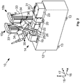
- FIG. 2 and 3 Reference is made to the perspective views of a machine tool 10 designed as a laser pressure welding machine for the production line in FIG Fig. 1 shows.
- the laser pressure welding machine 10 comprises a machine bed 12 which is supported on feet 13. From the feet 13 are in the perspective of the Fig. 2 not all to see. A motorized vice 14 as well as a first carrier 15 and a second carrier 15b are held on the machine bed 12. For the further explanations, it should be defined that the laser pressure welding machine 10 is located in a room with an x dimension 16, a y dimension 17 and a z dimension 18.
- the vice 14 comprises a first stationary anchor element 19 and a second stationary anchor element 20 arranged at a distance therefrom in the x direction 16.
- Four guide rods 21 are held between the two stationary anchor elements 19, 20, of which in FIG Fig. 2 and 3
- a slide 22 is slidably mounted on the guide rods, which is driven by a motor 23 via a spindle rod 24 guided through an internal thread in the second stationary anchor element 20 between the two stationary anchor elements 19, 20 in the x -Direction 16 can be moved back and forth.
- the above-mentioned raw parts can be pressed against one another in the x-direction 16.
- a first support plate 25 with a first chuck 26 is held on the first anchor element 19, directed towards the slide 22.
- a second support plate 27 with a second chuck 28 is held on the slide 22, directed towards the first anchor element 19.
- an unmachined part can be clamped in a manner known per se in order to then clamp the two against one another in the x direction 16, driven by the motor 23.
- the two supports 15, 16 are movably held in the x direction 16 on a guide rail 29 and a second guide rail 30, which is arranged behind the first guide rail 29 as seen in the y direction 17.
- Each carrier 15, 16 can be moved back and forth in the x-direction 16 on the guide rails 29, 30 via its own drive motor 31 and its own spindle rod 32.
- Each carrier 15, 16 has a slide system 33 on which a pivot arm 34 is held so as to be movable in the z direction 18.
- Each of the pivot arms 34 is in the Fig. 2 and 3 Drive system, which cannot be seen further, is moved in the z-direction 18.
- the exact mode of operation of the slide system 33 is not important for understanding the further explanations, which is why it will not be discussed in more detail here.
- a first scanner optics 35 of a first laser system is held, which in the Fig. 2 and 3 is not fully executed.
- a second scanner optics 36 of a second laser system is held on the pivot arm 34 of the second carrier 15b, which is also in the Fig. 2 and 3 is not fully executed.
- the pivot arms 34 hold their respective scanner optics 35, 36 pivotable about the y-axis 17. For pivoting, the pivot arms 34 are each supported by one in Fig. 2 and 3 Drive system that cannot be seen further.
- Fig. 3 Details of the scanner optics 35, 36 will be described below. For reasons of clarity, only the scanner optics 35, 36 are shown here Fig. 3 provided with reference numerals.
- Each scanner optics 35, 36 has one in the Fig. 2 and 3 laser light cable 37, shown cut off, via which the corresponding scanner optics 35, 36 are supplied with laser light 38.
- the laser light 38 is parallelized in a collimator 39 in a manner known per se and directed into a beam guiding device 41 via a deflecting mirror 40.
- the beam guiding device 41 of the first scanner optics 35 then outputs a first laser 42 generated from the laser light 38, while the beam guiding device 41 of the second scanner optics 36 outputs a second laser 43 generated from the laser light 38.
- the corresponding laser 42, 43 can be focused at any point within a work area 44 by means of adjustable mirrors and lenses (not shown). The exact mode of operation of this focusing is known per se and does not need to be explained further.
- the first scanner optics 35 can thus be roughly aligned with the second chuck 28, guided via the slide system 33 and the pivot arm 34 of the first carrier 15a.
- a blank clamped in the second chuck 28 can then be heated to a temperature above the recrystallization temperature of the blank in the second chuck 28 by means of the first laser 42 from the first scanner optics 35 at a point facing the first chuck 26.
- the second scanner optics 36 can be roughly aligned with the first chuck 26, guided via the slide system 33 and the pivot arm 34 of the second carrier 15.
- a blank clamped in the first chuck 26 can then be heated to a temperature above the recrystallization temperature of the blank in the first chuck 26 by means of the second laser 43 from the second scanner optics 36 at a point facing the second chuck 28. Finally, the two raw parts can be pressure-welded to one another at the heated point using the vice 14.
- the use of two scanner optics 35, 36 is shown in FIG Fig. 2 and 3 a technically particularly favorable design. For reasons of cost, however, it would in principle also be conceivable to use only the first scanner optics 35 carried only on the first carrier 15.
- FIG. 4a a first blank 45, which is clamped in the first chuck 26, as well as a second blank 46, which is clamped in the second chuck 28, is shown very specifically.
- the method shown for pressure welding the two blanks 45, 46, the two lasers 42, 43 work crosswise. This means that the first laser 42 heats the second blank 46 and the second laser 43 heats the first blank 45.
- the first blank 45 and the second blank 46 correspond to a first connecting section 47 'with a first connecting surface 47 and a second connecting section 48', respectively. with a second connecting surface 48.
- the two raw parts 45, 46 are heated directly at the connecting surfaces 47, 48 and brought together by pressing.
- the first scanner optics 35 and the second scanner optics 36 are aligned accordingly with the second blank 46 and the first blank 45.
- the aim of the alignment is that the working area 44 of each scanner optics 35, 36 is placed without overlapping with the other unheated part 46, 45, so that the unmachined parts 45, 46 are avoided opposite the lasers 42, 43 shade.
- dashed lines and apostrophes on the reference numerals indicate a position of the scanner optics 35, 36 in which the blanks 45, 46 shade one another in a partial area of the working area 44 of the scanner optics 35, 36.
- the irradiation process begins.
- the scanner optics 35, 36 aligned on blanks 45, 46 irradiate their connecting surfaces 47, 48 crosswise with the corresponding lasers 42, 43 and thus heat the connecting surfaces 47, 48 of the respective blanks 45, 46 to a temperature above its recrystallization temperature.
- the recrystallization temperature depends on the material. Steel, for example, has a recrystallization temperature that is around 600 ° C to 700 ° C, depending on the alloy components and the existing structural condition. In this case, however, the heating must not be above the melting temperature of the respective blank 45, 46, because otherwise the blank 45, 46 could be locally damaged and the pressure welding process could be impaired.
- the scanner optics 35, 36 move with the lasers 42, 43 over the connection surfaces 47, 48 within the working area 44 in curves. That is to say, the lasers 42, 43 are moved relative to the respective connection surfaces 47, 48.
- the raw parts 45, 46 can alternatively or additionally also be moved, which is shown in FIG Figure 4a is indicated by a rotary movement 62 about an axis of rotation 63 of the blanks 45, 46.
- the vice 14 of the laser pressure welding machine 10 would be Fig. 2 and 3 however, adjust accordingly to allow this movement.
- a spiral curve 49 is shown, which is traced or drawn on the connecting surface 47 of the first blank 45 by the second laser 43.
- the second laser 43 impinging on the first connecting surface 47 heats the first connecting surface 47 at specific points. With the movement of the second laser 43 through the second scanner optics 36, this punctual heating migrates along the spiral curve 49.
- FIG Figure 4c A diagram is shown in which thermal energy 51 at point 50 is plotted over time 52. In order to clarify the connection with the point 50, the diagram is provided with the reference symbol 50 '.
- the second laser 43 is on the first connection surface 47 at the heating point 50, the first connection surface 47 is heated in a heating phase 53 at the heating point 50 by a supply 54 (also called energy supply 54) of thermal energy 51.
- a supply 54 also called energy supply 54
- three heating phases 53 are indicated. That is, the second laser 43 sweeps over the heating point 50 three times and traces the spiral curve 49 three times.
- the supply 54 of thermal energy 51 is in Figure 4c indicated with reference symbols only in the first heating phase 53. If the second laser 43 is located at other points on the spiral curve 49 outside the heating point 50, it cools down again during cooling phases 55, which leads to a loss 56 of thermal energy 51 (also called energy dissipation 56) at the heating point 50.
- the total duration of a heating phase 53 together with a cooling phase 55 is referred to below as the overlap duration 59.
- the reciprocal of the overlap duration 59 is called the overlap frequency, which indicates how fast the second laser 43 moves along the spiral curve 49.
- the total duration of all heating phases 53 together with all cooling phases 55 is referred to below as heating duration 60.
- the heating duration 60 is reached when a thermal energy 51 with a temperature above the recrystallization temperature of the first blank 45 is reached at all points of the spiral curve 49 on the first connecting surface 47. In the same way as the heating or heating of the first connecting surface 47, the heating or heating of the second connecting surface 48 also takes place.
- burrs 61 can arise at the connection point of the two raw parts 45, 46, which can be removed again, for example, by cutting. After the two raw parts 45, 46 have been mechanically connected to one another, they can be removed from the vice 14 and processed further in the production line 1, for example.
- Figure 5a shows an alternative example (not part of the invention) of the heating process of the joint surfaces 47,48 of the blanks 45,46.
- Figure 5a For the sake of clarity, not all elements are provided with a reference number.
- the use of one of the two scanner optics 35, 36 can optionally be dispensed with, which is indicated by a bracket 64 around the first scanner optics 35.
- the first scanner optics 35 heats the first blank 45 while the second scanner optics 36 heats the second blank 46.
- the first laser 42 and the second laser 43 irradiate the connection surfaces 47, 48 not directly but indirectly via the outer surfaces of the raw parts in the area of the first connection section 47 'and the second connection section 48', respectively.
- the two lasers 42, 43 as seen from the axis of rotation 63, are aligned radially inward onto the corresponding part of the lateral surface of the first blank 45 or the second blank 46.
- the lasers 42, 43 therefore do not irradiate the blanks 46, 47 crosswise.
- the connecting surfaces 47, 48 are therefore not heated directly by irradiation with the lasers 42, 43. Rather, on the first blank 45, by irradiating the jacket surface in the first connecting section 47 'with the first laser 42, the first connecting surface 47 is indirectly heated to the temperature above the recrystallization temperature. In the same way, the second connection surface 48 is indirectly heated with the second laser 43 to the temperature above the recrystallization temperature, and the method can, as in FIG Figure 5a indicated in the same way as in Figure 4a .
- the second scanner optics 36 can be set up to shuttle the second laser 43 back and forth between the first connecting section 47 'and the second connecting section 48' to let.
- the idea of commuting is in Figure 5a indicated by a dashed illustration of the second laser 43 aligned with the first connecting section 47 '.
- connection areas 47 ', 48' could also be heated in a position of the two blanks 45, 46 in which the axes of rotation 63 of the two blanks 45, 46 are not on a line.
- the raw parts 45, 46 must therefore be aligned on a common pressing line, so that a simple vice 14 cannot be used to press the two raw parts 45, 46 together after heating. Rather, an actuator must be selected which is able to axially align the two raw parts 45, 46 with one another before they are pressed together.
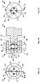
- the actuator is in Figure 5b indicated by the reference numeral 14 '.
- the end face of the first blank 45 has a recess 65 on the bottom side 66 of which four projections 67 are arranged.
- a first connecting surface 47 of the first blank 45 is arranged on each of these four projections 67.
- the four are surrounded by a circumferential wall 68.
- the end face of the second blank 46 has a projection 69 on the tip side 66 of which four projections 67 are likewise arranged.
- a second connecting surface 48 of the second blank 46 is arranged on each of these four projections 67.
- the projections 67 of the first blank 45 and of the second blank 46 are arranged in such a way that when the projection 69 is axially inserted into the recess 65, they can be placed one on top of the other and thus pressed against one another.
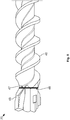
- FIG. 8 shows a schematic diagram of a drill 70.
- the drill 70 comprises the first blank 45 in the form of a drill head and the second blank 46 in the form of a cutting thread.
- Drill head 45 and cutting thread 46 basically have different requirement profiles, which is why it would be desirable to make them from different materials.
- connection surfaces 47, 48 are heated with lasers 42, 43
- the pressure welding process can be used to connect two materials which basically have completely different recrystallization temperatures.
- the drill head 45 can for example be made of a sintered hard material, while the cutting thread 46 can be made of a soft steel. This cannot be achieved with conventional pressure welding processes either.
Landscapes
- Engineering & Computer Science (AREA)
- Mechanical Engineering (AREA)
- Physics & Mathematics (AREA)
- Optics & Photonics (AREA)
- Plasma & Fusion (AREA)
- Laser Beam Processing (AREA)
- Pressure Welding/Diffusion-Bonding (AREA)
Applications Claiming Priority (2)
| Application Number | Priority Date | Filing Date | Title |
|---|---|---|---|
| DE102016122060.4A DE102016122060B3 (de) | 2016-11-16 | 2016-11-16 | Laserpressschweißen |
| PCT/EP2017/079336 WO2018091536A1 (de) | 2016-11-16 | 2017-11-15 | LASERPRESSSCHWEIßEN |
Publications (2)
| Publication Number | Publication Date |
|---|---|
| EP3541560A1 EP3541560A1 (de) | 2019-09-25 |
| EP3541560B1 true EP3541560B1 (de) | 2021-04-07 |
Family
ID=60388052
Family Applications (1)
| Application Number | Title | Priority Date | Filing Date |
|---|---|---|---|
| EP17800824.9A Active EP3541560B1 (de) | 2016-11-16 | 2017-11-15 | Pressschweissenverfahren und -vorrichtung mit unterstützung von laser |
Country Status (10)
| Country | Link |
|---|---|
| US (1) | US20190358738A1 (enExample) |
| EP (1) | EP3541560B1 (enExample) |
| JP (1) | JP6823192B2 (enExample) |
| KR (1) | KR20190087435A (enExample) |
| CN (1) | CN110234457B (enExample) |
| CA (1) | CA3043958C (enExample) |
| DE (1) | DE102016122060B3 (enExample) |
| ES (1) | ES2880286T3 (enExample) |
| TW (1) | TWI683717B (enExample) |
| WO (1) | WO2018091536A1 (enExample) |
Families Citing this family (4)
| Publication number | Priority date | Publication date | Assignee | Title |
|---|---|---|---|---|
| DE102016122063A1 (de) * | 2016-11-16 | 2018-05-17 | Csm Maschinen Gmbh | Pressverschweißtes Werkzeug |
| DE102020133116A1 (de) * | 2020-12-11 | 2022-06-15 | Peri Se | Verfahren und Vorrichtung zum Verschweißen eines ersten Bauelements mit einem zweiten Bauelement und Horizontalriegel |
| CN113305389A (zh) * | 2021-06-08 | 2021-08-27 | 武汉虹信科技发展有限责任公司 | 一种激光焊接装置及激光焊接方法 |
| CN119658142B (zh) * | 2025-01-23 | 2025-12-02 | 上海工程技术大学 | 一种用于轴类零件对接的激光辅助电弧焊方法 |
Family Cites Families (17)
| Publication number | Priority date | Publication date | Assignee | Title |
|---|---|---|---|---|
| JPS63183787A (ja) * | 1987-01-26 | 1988-07-29 | Mitsubishi Electric Corp | 固相接合装置 |
| JPH1080718A (ja) * | 1996-09-06 | 1998-03-31 | Kawasaki Steel Corp | 鋼管の製造方法 |
| US5815238A (en) * | 1996-09-10 | 1998-09-29 | Johnson & Johnson Vision Products, Inc. | Scanning laser demolding of ophthalmic lenses |
| JPH11320120A (ja) * | 1998-05-08 | 1999-11-24 | Nittetsu Boshoku Kk | 鋼管の現地接合法 |
| US6173886B1 (en) * | 1999-05-24 | 2001-01-16 | The University Of Tennessee Research Corportion | Method for joining dissimilar metals or alloys |
| DE102005024983A1 (de) | 2004-07-22 | 2006-02-16 | Sator Laser Gmbh | Vorrichtung zum Verschweißen von zwei Körpern |
| US20060231595A1 (en) * | 2005-04-14 | 2006-10-19 | James Florian Quinn | Method for friction stir welding of dissimilar materials |
| JP4868222B2 (ja) * | 2006-06-19 | 2012-02-01 | 日産自動車株式会社 | 異種金属パネルの接合方法及び接合装置 |
| DE102008014934A1 (de) | 2008-03-19 | 2009-09-24 | Daimler Ag | Anlage und Verfahren zum Pressschweißen |
| JP5597946B2 (ja) * | 2008-10-03 | 2014-10-01 | 日産自動車株式会社 | 金属の低温接合方法 |
| DE102008042663A1 (de) | 2008-10-08 | 2010-04-29 | Geiger Technologies Gmbh | Verfahren und Vorrichtung zum Fügen |
| DE202009008851U1 (de) * | 2009-06-27 | 2010-11-11 | Thyssenkrupp Drauz Nothelfer Gmbh | Spannsystem, zum Zusammenpressen von zu verschweißenden Blechen |
| DE102010007573B4 (de) * | 2010-02-10 | 2012-06-21 | Thyssenkrupp Lasertechnik Gmbh | Vorrichtung und Verfahren zum kontinuierlichen Verschweißen von Bändern und/oder Blechen |
| DE102011004104A1 (de) | 2011-02-15 | 2012-08-16 | Robert Bosch Gmbh | Verfahren zum Verbinden zweier Fügepartner mittels Laserstrahlung, Verwendung des Verfahrens sowie Fügepartner |
| CN103071910A (zh) * | 2013-01-14 | 2013-05-01 | 广东工业大学 | 一种双超声-高频感应复合精密微连接装置及方法 |
| CN203316920U (zh) * | 2013-05-17 | 2013-12-04 | 南昌航空大学 | 一种用于异种材料激光辅助热压焊接的滚压装置 |
| CN105108272B (zh) * | 2015-09-18 | 2018-01-30 | 邢台职业技术学院 | 一种异种金属焊接的方法和装置 |
-
2016
- 2016-11-16 DE DE102016122060.4A patent/DE102016122060B3/de not_active Expired - Fee Related
-
2017
- 2017-11-15 CN CN201780070774.3A patent/CN110234457B/zh active Active
- 2017-11-15 US US16/461,784 patent/US20190358738A1/en not_active Abandoned
- 2017-11-15 KR KR1020197014645A patent/KR20190087435A/ko not_active Ceased
- 2017-11-15 TW TW106139559A patent/TWI683717B/zh not_active IP Right Cessation
- 2017-11-15 JP JP2019547185A patent/JP6823192B2/ja not_active Expired - Fee Related
- 2017-11-15 CA CA3043958A patent/CA3043958C/en active Active
- 2017-11-15 EP EP17800824.9A patent/EP3541560B1/de active Active
- 2017-11-15 ES ES17800824T patent/ES2880286T3/es active Active
- 2017-11-15 WO PCT/EP2017/079336 patent/WO2018091536A1/de not_active Ceased
Non-Patent Citations (1)
| Title |
|---|
| None * |
Also Published As
| Publication number | Publication date |
|---|---|
| WO2018091536A1 (de) | 2018-05-24 |
| JP6823192B2 (ja) | 2021-01-27 |
| EP3541560A1 (de) | 2019-09-25 |
| CA3043958C (en) | 2021-02-23 |
| CN110234457B (zh) | 2021-04-30 |
| CN110234457A (zh) | 2019-09-13 |
| US20190358738A1 (en) | 2019-11-28 |
| TW201819087A (zh) | 2018-06-01 |
| JP2019535535A (ja) | 2019-12-12 |
| KR20190087435A (ko) | 2019-07-24 |
| ES2880286T3 (es) | 2021-11-24 |
| DE102016122060B3 (de) | 2018-03-29 |
| TWI683717B (zh) | 2020-02-01 |
| CA3043958A1 (en) | 2018-05-24 |
Similar Documents
| Publication | Publication Date | Title |
|---|---|---|
| DE102007023017B4 (de) | Vorrichtung und Verfahren zum Herstellen von Tailored Blanks | |
| EP2416918B1 (de) | Verfahren und vorrichtung zum verbinden der enden von rohren aus stahl mittels orbitalschweissen in hybridtechnik | |
| EP0790875B1 (de) | Verfahren und vorrichtung zur herstellung von metallischen werkstücken | |
| EP3256285B1 (de) | Bestrahlungseinrichtung, bearbeitungsmaschine und verfahren zum herstellen einer schicht bzw. eines teilbereichs einer schicht eines dreidimensionalen bauteils | |
| EP3541560B1 (de) | Pressschweissenverfahren und -vorrichtung mit unterstützung von laser | |
| EP2142333B1 (de) | Vorrichtung zum bearbeiten einer oberfläche eines werkstücks mittels laserstrahlung | |
| EP3463742B1 (de) | Werkzeugmaschine zum auftragsschweissen | |
| EP3191254B1 (de) | Laser-ablations- und schweissverfahren für werkstücke | |
| EP2285522B1 (de) | Laserbearbeitungsmaschine mit erweitertem arbeitsraum | |
| EP2691206B1 (de) | Verfahren zur laserstrahlbearbeitung eines werkstücks | |
| DE69818134T2 (de) | Verfahren und Vorrichtung zum Schweissen eines Werkstücks | |
| WO2018059901A1 (de) | Verfahren und laserbearbeitungsmaschine zum laserschweissen eines ersten und eines zweiten werkstückabschnitts | |
| DE102014203025A1 (de) | Verfahren zum Laserstrahlschweißen und Schweißkopf | |
| EP3386677B1 (de) | Vorrichtung und verfahren zur bearbeitung eines werkstückes mittels laserstrahlung | |
| WO2020165140A1 (de) | VORRICHTUNG UND VERFAHREN ZUM HERSTELLEN VON LASERGESCHWEIßTEN BLECHEN, INSBESONDERE ZUM DURCHTAKTEN VON DERARTIGEN BLECHEN SOWIE VERWENDUNG DER VORRICHTUNG UND DES VERFAHRENS | |
| EP2316606A2 (de) | Vorrichtung für das Durchstrahlschweißen von Bauteilen über eine ringförmige Kontaktzone | |
| DE102012017130B4 (de) | Laser-Rohreinschweißen | |
| WO2017137391A1 (de) | Verfahren zum herstellen einer schicht bzw. eines teilbereichs einer schicht eines dreidimensionalen bauteils; entsprechendes computerprogrammprodukt | |
| DE3733568A1 (de) | Verfahren zur herstellung von schweissverbindungen an karosserieteilen und anderen blechteilen und robotersystem | |
| EP2130638B1 (de) | Verfahren zur Kantenbehandlung metallischer Werkstücke unter Verwendung eines Laserstrahles | |
| DE102009049892B3 (de) | Vorrichtung zum Verbinden eines Werkstückes mit einem Fügeteil mittels Laserstrahlung | |
| DE102004050819B4 (de) | Verfahren und Vorrichtung zum Laserstrahlbearbeiten | |
| EP3068911B1 (de) | In-line verfahren und in-line fertigungsanlage | |
| DE4339661C2 (de) | Verfahren zum Herstellen von röhrenförmigen Rohlingen aus Fein- oder Feinstblech | |
| EP3746288B1 (de) | Vorrichtung zum fügen, insbesondere laserschweissen, zweier bauteile und betriebsverfahren für eine solche fügevorrichtung |
Legal Events
| Date | Code | Title | Description |
|---|---|---|---|
| STAA | Information on the status of an ep patent application or granted ep patent |
Free format text: STATUS: UNKNOWN |
|
| STAA | Information on the status of an ep patent application or granted ep patent |
Free format text: STATUS: THE INTERNATIONAL PUBLICATION HAS BEEN MADE |
|
| PUAI | Public reference made under article 153(3) epc to a published international application that has entered the european phase |
Free format text: ORIGINAL CODE: 0009012 |
|
| STAA | Information on the status of an ep patent application or granted ep patent |
Free format text: STATUS: REQUEST FOR EXAMINATION WAS MADE |
|
| 17P | Request for examination filed |
Effective date: 20190528 |
|
| AK | Designated contracting states |
Kind code of ref document: A1 Designated state(s): AL AT BE BG CH CY CZ DE DK EE ES FI FR GB GR HR HU IE IS IT LI LT LU LV MC MK MT NL NO PL PT RO RS SE SI SK SM TR |
|
| AX | Request for extension of the european patent |
Extension state: BA ME |
|
| DAV | Request for validation of the european patent (deleted) | ||
| DAX | Request for extension of the european patent (deleted) | ||
| GRAP | Despatch of communication of intention to grant a patent |
Free format text: ORIGINAL CODE: EPIDOSNIGR1 |
|
| STAA | Information on the status of an ep patent application or granted ep patent |
Free format text: STATUS: GRANT OF PATENT IS INTENDED |
|
| GRAJ | Information related to disapproval of communication of intention to grant by the applicant or resumption of examination proceedings by the epo deleted |
Free format text: ORIGINAL CODE: EPIDOSDIGR1 |
|
| STAA | Information on the status of an ep patent application or granted ep patent |
Free format text: STATUS: REQUEST FOR EXAMINATION WAS MADE |
|
| GRAP | Despatch of communication of intention to grant a patent |
Free format text: ORIGINAL CODE: EPIDOSNIGR1 |
|
| STAA | Information on the status of an ep patent application or granted ep patent |
Free format text: STATUS: GRANT OF PATENT IS INTENDED |
|
| INTG | Intention to grant announced |
Effective date: 20201008 |
|
| INTG | Intention to grant announced |
Effective date: 20201020 |
|
| GRAS | Grant fee paid |
Free format text: ORIGINAL CODE: EPIDOSNIGR3 |
|
| GRAA | (expected) grant |
Free format text: ORIGINAL CODE: 0009210 |
|
| STAA | Information on the status of an ep patent application or granted ep patent |
Free format text: STATUS: THE PATENT HAS BEEN GRANTED |
|
| AK | Designated contracting states |
Kind code of ref document: B1 Designated state(s): AL AT BE BG CH CY CZ DE DK EE ES FI FR GB GR HR HU IE IS IT LI LT LU LV MC MK MT NL NO PL PT RO RS SE SI SK SM TR |
|
| REG | Reference to a national code |
Ref country code: GB Ref legal event code: FG4D Free format text: NOT ENGLISH |
|
| REG | Reference to a national code |
Ref country code: AT Ref legal event code: REF Ref document number: 1379042 Country of ref document: AT Kind code of ref document: T Effective date: 20210415 Ref country code: CH Ref legal event code: EP |
|
| REG | Reference to a national code |
Ref country code: DE Ref legal event code: R096 Ref document number: 502017010030 Country of ref document: DE |
|
| REG | Reference to a national code |
Ref country code: IE Ref legal event code: FG4D Free format text: LANGUAGE OF EP DOCUMENT: GERMAN |
|
| REG | Reference to a national code |
Ref country code: LT Ref legal event code: MG9D |
|
| REG | Reference to a national code |
Ref country code: NL Ref legal event code: MP Effective date: 20210407 |
|
| PG25 | Lapsed in a contracting state [announced via postgrant information from national office to epo] |
Ref country code: FI Free format text: LAPSE BECAUSE OF FAILURE TO SUBMIT A TRANSLATION OF THE DESCRIPTION OR TO PAY THE FEE WITHIN THE PRESCRIBED TIME-LIMIT Effective date: 20210407 Ref country code: LT Free format text: LAPSE BECAUSE OF FAILURE TO SUBMIT A TRANSLATION OF THE DESCRIPTION OR TO PAY THE FEE WITHIN THE PRESCRIBED TIME-LIMIT Effective date: 20210407 Ref country code: NL Free format text: LAPSE BECAUSE OF FAILURE TO SUBMIT A TRANSLATION OF THE DESCRIPTION OR TO PAY THE FEE WITHIN THE PRESCRIBED TIME-LIMIT Effective date: 20210407 Ref country code: HR Free format text: LAPSE BECAUSE OF FAILURE TO SUBMIT A TRANSLATION OF THE DESCRIPTION OR TO PAY THE FEE WITHIN THE PRESCRIBED TIME-LIMIT Effective date: 20210407 Ref country code: BG Free format text: LAPSE BECAUSE OF FAILURE TO SUBMIT A TRANSLATION OF THE DESCRIPTION OR TO PAY THE FEE WITHIN THE PRESCRIBED TIME-LIMIT Effective date: 20210707 |
|
| REG | Reference to a national code |
Ref country code: ES Ref legal event code: FG2A Ref document number: 2880286 Country of ref document: ES Kind code of ref document: T3 Effective date: 20211124 |
|
| PG25 | Lapsed in a contracting state [announced via postgrant information from national office to epo] |
Ref country code: GR Free format text: LAPSE BECAUSE OF FAILURE TO SUBMIT A TRANSLATION OF THE DESCRIPTION OR TO PAY THE FEE WITHIN THE PRESCRIBED TIME-LIMIT Effective date: 20210708 Ref country code: IS Free format text: LAPSE BECAUSE OF FAILURE TO SUBMIT A TRANSLATION OF THE DESCRIPTION OR TO PAY THE FEE WITHIN THE PRESCRIBED TIME-LIMIT Effective date: 20210807 Ref country code: PT Free format text: LAPSE BECAUSE OF FAILURE TO SUBMIT A TRANSLATION OF THE DESCRIPTION OR TO PAY THE FEE WITHIN THE PRESCRIBED TIME-LIMIT Effective date: 20210809 Ref country code: PL Free format text: LAPSE BECAUSE OF FAILURE TO SUBMIT A TRANSLATION OF THE DESCRIPTION OR TO PAY THE FEE WITHIN THE PRESCRIBED TIME-LIMIT Effective date: 20210407 Ref country code: NO Free format text: LAPSE BECAUSE OF FAILURE TO SUBMIT A TRANSLATION OF THE DESCRIPTION OR TO PAY THE FEE WITHIN THE PRESCRIBED TIME-LIMIT Effective date: 20210707 Ref country code: LV Free format text: LAPSE BECAUSE OF FAILURE TO SUBMIT A TRANSLATION OF THE DESCRIPTION OR TO PAY THE FEE WITHIN THE PRESCRIBED TIME-LIMIT Effective date: 20210407 Ref country code: SE Free format text: LAPSE BECAUSE OF FAILURE TO SUBMIT A TRANSLATION OF THE DESCRIPTION OR TO PAY THE FEE WITHIN THE PRESCRIBED TIME-LIMIT Effective date: 20210407 Ref country code: RS Free format text: LAPSE BECAUSE OF FAILURE TO SUBMIT A TRANSLATION OF THE DESCRIPTION OR TO PAY THE FEE WITHIN THE PRESCRIBED TIME-LIMIT Effective date: 20210407 |
|
| REG | Reference to a national code |
Ref country code: DE Ref legal event code: R097 Ref document number: 502017010030 Country of ref document: DE |
|
| PG25 | Lapsed in a contracting state [announced via postgrant information from national office to epo] |
Ref country code: SK Free format text: LAPSE BECAUSE OF FAILURE TO SUBMIT A TRANSLATION OF THE DESCRIPTION OR TO PAY THE FEE WITHIN THE PRESCRIBED TIME-LIMIT Effective date: 20210407 Ref country code: SM Free format text: LAPSE BECAUSE OF FAILURE TO SUBMIT A TRANSLATION OF THE DESCRIPTION OR TO PAY THE FEE WITHIN THE PRESCRIBED TIME-LIMIT Effective date: 20210407 Ref country code: RO Free format text: LAPSE BECAUSE OF FAILURE TO SUBMIT A TRANSLATION OF THE DESCRIPTION OR TO PAY THE FEE WITHIN THE PRESCRIBED TIME-LIMIT Effective date: 20210407 Ref country code: EE Free format text: LAPSE BECAUSE OF FAILURE TO SUBMIT A TRANSLATION OF THE DESCRIPTION OR TO PAY THE FEE WITHIN THE PRESCRIBED TIME-LIMIT Effective date: 20210407 Ref country code: DK Free format text: LAPSE BECAUSE OF FAILURE TO SUBMIT A TRANSLATION OF THE DESCRIPTION OR TO PAY THE FEE WITHIN THE PRESCRIBED TIME-LIMIT Effective date: 20210407 |
|
| PLBE | No opposition filed within time limit |
Free format text: ORIGINAL CODE: 0009261 |
|
| STAA | Information on the status of an ep patent application or granted ep patent |
Free format text: STATUS: NO OPPOSITION FILED WITHIN TIME LIMIT |
|
| 26N | No opposition filed |
Effective date: 20220110 |
|
| PG25 | Lapsed in a contracting state [announced via postgrant information from national office to epo] |
Ref country code: IS Free format text: LAPSE BECAUSE OF FAILURE TO SUBMIT A TRANSLATION OF THE DESCRIPTION OR TO PAY THE FEE WITHIN THE PRESCRIBED TIME-LIMIT Effective date: 20210807 Ref country code: AL Free format text: LAPSE BECAUSE OF FAILURE TO SUBMIT A TRANSLATION OF THE DESCRIPTION OR TO PAY THE FEE WITHIN THE PRESCRIBED TIME-LIMIT Effective date: 20210407 |
|
| REG | Reference to a national code |
Ref country code: DE Ref legal event code: R119 Ref document number: 502017010030 Country of ref document: DE |
|
| PG25 | Lapsed in a contracting state [announced via postgrant information from national office to epo] |
Ref country code: MC Free format text: LAPSE BECAUSE OF FAILURE TO SUBMIT A TRANSLATION OF THE DESCRIPTION OR TO PAY THE FEE WITHIN THE PRESCRIBED TIME-LIMIT Effective date: 20210407 |
|
| REG | Reference to a national code |
Ref country code: CH Ref legal event code: PL |
|
| GBPC | Gb: european patent ceased through non-payment of renewal fee |
Effective date: 20211115 |
|
| PG25 | Lapsed in a contracting state [announced via postgrant information from national office to epo] |
Ref country code: LU Free format text: LAPSE BECAUSE OF NON-PAYMENT OF DUE FEES Effective date: 20211115 Ref country code: BE Free format text: LAPSE BECAUSE OF NON-PAYMENT OF DUE FEES Effective date: 20211130 |
|
| REG | Reference to a national code |
Ref country code: BE Ref legal event code: MM Effective date: 20211130 |
|
| PG25 | Lapsed in a contracting state [announced via postgrant information from national office to epo] |
Ref country code: LI Free format text: LAPSE BECAUSE OF NON-PAYMENT OF DUE FEES Effective date: 20211130 Ref country code: CH Free format text: LAPSE BECAUSE OF NON-PAYMENT OF DUE FEES Effective date: 20211130 |
|
| PG25 | Lapsed in a contracting state [announced via postgrant information from national office to epo] |
Ref country code: IE Free format text: LAPSE BECAUSE OF NON-PAYMENT OF DUE FEES Effective date: 20211115 Ref country code: GB Free format text: LAPSE BECAUSE OF NON-PAYMENT OF DUE FEES Effective date: 20211115 Ref country code: DE Free format text: LAPSE BECAUSE OF NON-PAYMENT OF DUE FEES Effective date: 20220601 |
|
| PG25 | Lapsed in a contracting state [announced via postgrant information from national office to epo] |
Ref country code: CY Free format text: LAPSE BECAUSE OF FAILURE TO SUBMIT A TRANSLATION OF THE DESCRIPTION OR TO PAY THE FEE WITHIN THE PRESCRIBED TIME-LIMIT Effective date: 20210407 |
|
| PG25 | Lapsed in a contracting state [announced via postgrant information from national office to epo] |
Ref country code: HU Free format text: LAPSE BECAUSE OF FAILURE TO SUBMIT A TRANSLATION OF THE DESCRIPTION OR TO PAY THE FEE WITHIN THE PRESCRIBED TIME-LIMIT; INVALID AB INITIO Effective date: 20171115 |
|
| REG | Reference to a national code |
Ref country code: AT Ref legal event code: MM01 Ref document number: 1379042 Country of ref document: AT Kind code of ref document: T Effective date: 20221115 |
|
| PG25 | Lapsed in a contracting state [announced via postgrant information from national office to epo] |
Ref country code: AT Free format text: LAPSE BECAUSE OF NON-PAYMENT OF DUE FEES Effective date: 20221115 |
|
| PG25 | Lapsed in a contracting state [announced via postgrant information from national office to epo] |
Ref country code: MK Free format text: LAPSE BECAUSE OF FAILURE TO SUBMIT A TRANSLATION OF THE DESCRIPTION OR TO PAY THE FEE WITHIN THE PRESCRIBED TIME-LIMIT Effective date: 20210407 |
|
| PG25 | Lapsed in a contracting state [announced via postgrant information from national office to epo] |
Ref country code: TR Free format text: LAPSE BECAUSE OF FAILURE TO SUBMIT A TRANSLATION OF THE DESCRIPTION OR TO PAY THE FEE WITHIN THE PRESCRIBED TIME-LIMIT Effective date: 20210407 |
|
| PG25 | Lapsed in a contracting state [announced via postgrant information from national office to epo] |
Ref country code: MT Free format text: LAPSE BECAUSE OF FAILURE TO SUBMIT A TRANSLATION OF THE DESCRIPTION OR TO PAY THE FEE WITHIN THE PRESCRIBED TIME-LIMIT Effective date: 20210407 |
|
| PGFP | Annual fee paid to national office [announced via postgrant information from national office to epo] |
Ref country code: FR Payment date: 20241120 Year of fee payment: 8 |
|
| PGFP | Annual fee paid to national office [announced via postgrant information from national office to epo] |
Ref country code: CZ Payment date: 20241004 Year of fee payment: 8 |
|
| PGFP | Annual fee paid to national office [announced via postgrant information from national office to epo] |
Ref country code: IT Payment date: 20241112 Year of fee payment: 8 Ref country code: ES Payment date: 20241202 Year of fee payment: 8 |