EP3541309B1 - Surgical instrument with removable portion to facilitate cleaning - Google Patents
Surgical instrument with removable portion to facilitate cleaning Download PDFInfo
- Publication number
- EP3541309B1 EP3541309B1 EP17812124.0A EP17812124A EP3541309B1 EP 3541309 B1 EP3541309 B1 EP 3541309B1 EP 17812124 A EP17812124 A EP 17812124A EP 3541309 B1 EP3541309 B1 EP 3541309B1
- Authority
- EP
- European Patent Office
- Prior art keywords
- sheath
- assembly
- surgical instrument
- clamp arm
- cover
- Prior art date
- Legal status (The legal status is an assumption and is not a legal conclusion. Google has not performed a legal analysis and makes no representation as to the accuracy of the status listed.)
- Active
Links
- 238000004140 cleaning Methods 0.000 title claims description 23
- 230000008878 coupling Effects 0.000 claims description 76
- 238000010168 coupling process Methods 0.000 claims description 76
- 238000005859 coupling reaction Methods 0.000 claims description 76
- 238000000034 method Methods 0.000 claims description 23
- 239000012530 fluid Substances 0.000 claims description 4
- 238000004891 communication Methods 0.000 claims description 3
- 239000012636 effector Substances 0.000 description 37
- 238000005516 engineering process Methods 0.000 description 11
- 239000000463 material Substances 0.000 description 10
- 238000011282 treatment Methods 0.000 description 10
- 230000003213 activating effect Effects 0.000 description 9
- 230000000712 assembly Effects 0.000 description 9
- 238000000429 assembly Methods 0.000 description 9
- 210000003813 thumb Anatomy 0.000 description 9
- 210000003811 finger Anatomy 0.000 description 7
- 230000001954 sterilising effect Effects 0.000 description 7
- 230000009977 dual effect Effects 0.000 description 6
- 238000001356 surgical procedure Methods 0.000 description 6
- 230000008901 benefit Effects 0.000 description 5
- 150000001875 compounds Chemical class 0.000 description 5
- 230000002441 reversible effect Effects 0.000 description 5
- 230000037361 pathway Effects 0.000 description 4
- 230000005855 radiation Effects 0.000 description 4
- 230000001112 coagulating effect Effects 0.000 description 3
- 230000014509 gene expression Effects 0.000 description 3
- 230000004048 modification Effects 0.000 description 3
- 238000012986 modification Methods 0.000 description 3
- 230000009471 action Effects 0.000 description 2
- 230000004913 activation Effects 0.000 description 2
- 230000015271 coagulation Effects 0.000 description 2
- 238000005345 coagulation Methods 0.000 description 2
- 238000011065 in-situ storage Methods 0.000 description 2
- 239000007769 metal material Substances 0.000 description 2
- 238000002355 open surgical procedure Methods 0.000 description 2
- 230000010355 oscillation Effects 0.000 description 2
- 230000036961 partial effect Effects 0.000 description 2
- 102000004169 proteins and genes Human genes 0.000 description 2
- 108090000623 proteins and genes Proteins 0.000 description 2
- 230000002829 reductive effect Effects 0.000 description 2
- 238000007789 sealing Methods 0.000 description 2
- 238000004659 sterilization and disinfection Methods 0.000 description 2
- 238000002604 ultrasonography Methods 0.000 description 2
- 241000894006 Bacteria Species 0.000 description 1
- IAYPIBMASNFSPL-UHFFFAOYSA-N Ethylene oxide Chemical compound C1CO1 IAYPIBMASNFSPL-UHFFFAOYSA-N 0.000 description 1
- 239000004775 Tyvek Substances 0.000 description 1
- 229920000690 Tyvek Polymers 0.000 description 1
- 230000006978 adaptation Effects 0.000 description 1
- 230000009286 beneficial effect Effects 0.000 description 1
- 239000008280 blood Substances 0.000 description 1
- 210000004369 blood Anatomy 0.000 description 1
- 210000004204 blood vessel Anatomy 0.000 description 1
- 210000001124 body fluid Anatomy 0.000 description 1
- 230000015556 catabolic process Effects 0.000 description 1
- 230000006835 compression Effects 0.000 description 1
- 238000007906 compression Methods 0.000 description 1
- 238000006731 degradation reaction Methods 0.000 description 1
- 230000001419 dependent effect Effects 0.000 description 1
- 238000002955 isolation Methods 0.000 description 1
- 230000000670 limiting effect Effects 0.000 description 1
- 239000007788 liquid Substances 0.000 description 1
- 210000004185 liver Anatomy 0.000 description 1
- 230000010358 mechanical oscillation Effects 0.000 description 1
- 230000007246 mechanism Effects 0.000 description 1
- 230000002265 prevention Effects 0.000 description 1
- 230000009467 reduction Effects 0.000 description 1
- 238000002271 resection Methods 0.000 description 1
- 230000004044 response Effects 0.000 description 1
- 238000005096 rolling process Methods 0.000 description 1
- 230000003068 static effect Effects 0.000 description 1
- 239000013589 supplement Substances 0.000 description 1
Images


Classifications
-
- A—HUMAN NECESSITIES
- A61—MEDICAL OR VETERINARY SCIENCE; HYGIENE
- A61B—DIAGNOSIS; SURGERY; IDENTIFICATION
- A61B17/00—Surgical instruments, devices or methods, e.g. tourniquets
- A61B17/28—Surgical forceps
- A61B17/2804—Surgical forceps with two or more pivotal connections
-
- A—HUMAN NECESSITIES
- A61—MEDICAL OR VETERINARY SCIENCE; HYGIENE
- A61B—DIAGNOSIS; SURGERY; IDENTIFICATION
- A61B17/00—Surgical instruments, devices or methods, e.g. tourniquets
- A61B17/32—Surgical cutting instruments
- A61B17/320068—Surgical cutting instruments using mechanical vibrations, e.g. ultrasonic
- A61B17/320092—Surgical cutting instruments using mechanical vibrations, e.g. ultrasonic with additional movable means for clamping or cutting tissue, e.g. with a pivoting jaw
-
- A—HUMAN NECESSITIES
- A61—MEDICAL OR VETERINARY SCIENCE; HYGIENE
- A61B—DIAGNOSIS; SURGERY; IDENTIFICATION
- A61B18/00—Surgical instruments, devices or methods for transferring non-mechanical forms of energy to or from the body
- A61B18/04—Surgical instruments, devices or methods for transferring non-mechanical forms of energy to or from the body by heating
- A61B18/12—Surgical instruments, devices or methods for transferring non-mechanical forms of energy to or from the body by heating by passing a current through the tissue to be heated, e.g. high-frequency current
- A61B18/14—Probes or electrodes therefor
- A61B18/1442—Probes having pivoting end effectors, e.g. forceps
- A61B18/1445—Probes having pivoting end effectors, e.g. forceps at the distal end of a shaft, e.g. forceps or scissors at the end of a rigid rod
-
- A—HUMAN NECESSITIES
- A61—MEDICAL OR VETERINARY SCIENCE; HYGIENE
- A61B—DIAGNOSIS; SURGERY; IDENTIFICATION
- A61B18/00—Surgical instruments, devices or methods for transferring non-mechanical forms of energy to or from the body
- A61B18/04—Surgical instruments, devices or methods for transferring non-mechanical forms of energy to or from the body by heating
- A61B18/12—Surgical instruments, devices or methods for transferring non-mechanical forms of energy to or from the body by heating by passing a current through the tissue to be heated, e.g. high-frequency current
- A61B18/1206—Generators therefor
-
- A—HUMAN NECESSITIES
- A61—MEDICAL OR VETERINARY SCIENCE; HYGIENE
- A61B—DIAGNOSIS; SURGERY; IDENTIFICATION
- A61B17/00—Surgical instruments, devices or methods, e.g. tourniquets
- A61B2017/00017—Electrical control of surgical instruments
- A61B2017/00022—Sensing or detecting at the treatment site
- A61B2017/00106—Sensing or detecting at the treatment site ultrasonic
-
- A—HUMAN NECESSITIES
- A61—MEDICAL OR VETERINARY SCIENCE; HYGIENE
- A61B—DIAGNOSIS; SURGERY; IDENTIFICATION
- A61B17/00—Surgical instruments, devices or methods, e.g. tourniquets
- A61B2017/00367—Details of actuation of instruments, e.g. relations between pushing buttons, or the like, and activation of the tool, working tip, or the like
-
- A—HUMAN NECESSITIES
- A61—MEDICAL OR VETERINARY SCIENCE; HYGIENE
- A61B—DIAGNOSIS; SURGERY; IDENTIFICATION
- A61B17/00—Surgical instruments, devices or methods, e.g. tourniquets
- A61B2017/0042—Surgical instruments, devices or methods, e.g. tourniquets with special provisions for gripping
- A61B2017/00424—Surgical instruments, devices or methods, e.g. tourniquets with special provisions for gripping ergonomic, e.g. fitting in fist
-
- A—HUMAN NECESSITIES
- A61—MEDICAL OR VETERINARY SCIENCE; HYGIENE
- A61B—DIAGNOSIS; SURGERY; IDENTIFICATION
- A61B17/00—Surgical instruments, devices or methods, e.g. tourniquets
- A61B2017/0046—Surgical instruments, devices or methods, e.g. tourniquets with a releasable handle; with handle and operating part separable
-
- A—HUMAN NECESSITIES
- A61—MEDICAL OR VETERINARY SCIENCE; HYGIENE
- A61B—DIAGNOSIS; SURGERY; IDENTIFICATION
- A61B17/00—Surgical instruments, devices or methods, e.g. tourniquets
- A61B2017/00477—Coupling
-
- A—HUMAN NECESSITIES
- A61—MEDICAL OR VETERINARY SCIENCE; HYGIENE
- A61B—DIAGNOSIS; SURGERY; IDENTIFICATION
- A61B17/00—Surgical instruments, devices or methods, e.g. tourniquets
- A61B2017/00526—Methods of manufacturing
-
- A—HUMAN NECESSITIES
- A61—MEDICAL OR VETERINARY SCIENCE; HYGIENE
- A61B—DIAGNOSIS; SURGERY; IDENTIFICATION
- A61B17/00—Surgical instruments, devices or methods, e.g. tourniquets
- A61B2017/00831—Material properties
- A61B2017/00876—Material properties magnetic
-
- A—HUMAN NECESSITIES
- A61—MEDICAL OR VETERINARY SCIENCE; HYGIENE
- A61B—DIAGNOSIS; SURGERY; IDENTIFICATION
- A61B17/00—Surgical instruments, devices or methods, e.g. tourniquets
- A61B17/28—Surgical forceps
- A61B17/2812—Surgical forceps with a single pivotal connection
- A61B17/282—Jaws
- A61B2017/2825—Inserts of different material in jaws
-
- A—HUMAN NECESSITIES
- A61—MEDICAL OR VETERINARY SCIENCE; HYGIENE
- A61B—DIAGNOSIS; SURGERY; IDENTIFICATION
- A61B17/00—Surgical instruments, devices or methods, e.g. tourniquets
- A61B17/28—Surgical forceps
- A61B17/2812—Surgical forceps with a single pivotal connection
- A61B17/2841—Handles
- A61B2017/2845—Handles with a spring pushing the handle back
-
- A—HUMAN NECESSITIES
- A61—MEDICAL OR VETERINARY SCIENCE; HYGIENE
- A61B—DIAGNOSIS; SURGERY; IDENTIFICATION
- A61B17/00—Surgical instruments, devices or methods, e.g. tourniquets
- A61B17/32—Surgical cutting instruments
- A61B17/320068—Surgical cutting instruments using mechanical vibrations, e.g. ultrasonic
- A61B2017/320072—Working tips with special features, e.g. extending parts
- A61B2017/320074—Working tips with special features, e.g. extending parts blade
-
- A—HUMAN NECESSITIES
- A61—MEDICAL OR VETERINARY SCIENCE; HYGIENE
- A61B—DIAGNOSIS; SURGERY; IDENTIFICATION
- A61B17/00—Surgical instruments, devices or methods, e.g. tourniquets
- A61B17/32—Surgical cutting instruments
- A61B17/320068—Surgical cutting instruments using mechanical vibrations, e.g. ultrasonic
- A61B2017/320082—Surgical cutting instruments using mechanical vibrations, e.g. ultrasonic for incising tissue
-
- A—HUMAN NECESSITIES
- A61—MEDICAL OR VETERINARY SCIENCE; HYGIENE
- A61B—DIAGNOSIS; SURGERY; IDENTIFICATION
- A61B17/00—Surgical instruments, devices or methods, e.g. tourniquets
- A61B17/32—Surgical cutting instruments
- A61B17/320068—Surgical cutting instruments using mechanical vibrations, e.g. ultrasonic
- A61B2017/320084—Irrigation sleeves
-
- A—HUMAN NECESSITIES
- A61—MEDICAL OR VETERINARY SCIENCE; HYGIENE
- A61B—DIAGNOSIS; SURGERY; IDENTIFICATION
- A61B17/00—Surgical instruments, devices or methods, e.g. tourniquets
- A61B17/32—Surgical cutting instruments
- A61B17/320068—Surgical cutting instruments using mechanical vibrations, e.g. ultrasonic
- A61B2017/320088—Surgical cutting instruments using mechanical vibrations, e.g. ultrasonic with acoustic insulation, e.g. elements for damping vibrations between horn and surrounding sheath
-
- A—HUMAN NECESSITIES
- A61—MEDICAL OR VETERINARY SCIENCE; HYGIENE
- A61B—DIAGNOSIS; SURGERY; IDENTIFICATION
- A61B17/00—Surgical instruments, devices or methods, e.g. tourniquets
- A61B17/32—Surgical cutting instruments
- A61B17/320068—Surgical cutting instruments using mechanical vibrations, e.g. ultrasonic
- A61B17/320092—Surgical cutting instruments using mechanical vibrations, e.g. ultrasonic with additional movable means for clamping or cutting tissue, e.g. with a pivoting jaw
- A61B2017/320093—Surgical cutting instruments using mechanical vibrations, e.g. ultrasonic with additional movable means for clamping or cutting tissue, e.g. with a pivoting jaw additional movable means performing cutting operation
-
- A—HUMAN NECESSITIES
- A61—MEDICAL OR VETERINARY SCIENCE; HYGIENE
- A61B—DIAGNOSIS; SURGERY; IDENTIFICATION
- A61B17/00—Surgical instruments, devices or methods, e.g. tourniquets
- A61B17/32—Surgical cutting instruments
- A61B17/320068—Surgical cutting instruments using mechanical vibrations, e.g. ultrasonic
- A61B17/320092—Surgical cutting instruments using mechanical vibrations, e.g. ultrasonic with additional movable means for clamping or cutting tissue, e.g. with a pivoting jaw
- A61B2017/320094—Surgical cutting instruments using mechanical vibrations, e.g. ultrasonic with additional movable means for clamping or cutting tissue, e.g. with a pivoting jaw additional movable means performing clamping operation
-
- A—HUMAN NECESSITIES
- A61—MEDICAL OR VETERINARY SCIENCE; HYGIENE
- A61B—DIAGNOSIS; SURGERY; IDENTIFICATION
- A61B17/00—Surgical instruments, devices or methods, e.g. tourniquets
- A61B17/32—Surgical cutting instruments
- A61B17/320068—Surgical cutting instruments using mechanical vibrations, e.g. ultrasonic
- A61B17/320092—Surgical cutting instruments using mechanical vibrations, e.g. ultrasonic with additional movable means for clamping or cutting tissue, e.g. with a pivoting jaw
- A61B2017/320095—Surgical cutting instruments using mechanical vibrations, e.g. ultrasonic with additional movable means for clamping or cutting tissue, e.g. with a pivoting jaw with sealing or cauterizing means
-
- A—HUMAN NECESSITIES
- A61—MEDICAL OR VETERINARY SCIENCE; HYGIENE
- A61B—DIAGNOSIS; SURGERY; IDENTIFICATION
- A61B18/00—Surgical instruments, devices or methods for transferring non-mechanical forms of energy to or from the body
- A61B2018/00571—Surgical instruments, devices or methods for transferring non-mechanical forms of energy to or from the body for achieving a particular surgical effect
- A61B2018/0063—Sealing
-
- A—HUMAN NECESSITIES
- A61—MEDICAL OR VETERINARY SCIENCE; HYGIENE
- A61B—DIAGNOSIS; SURGERY; IDENTIFICATION
- A61B18/00—Surgical instruments, devices or methods for transferring non-mechanical forms of energy to or from the body
- A61B2018/00636—Sensing and controlling the application of energy
- A61B2018/00642—Sensing and controlling the application of energy with feedback, i.e. closed loop control
-
- A—HUMAN NECESSITIES
- A61—MEDICAL OR VETERINARY SCIENCE; HYGIENE
- A61B—DIAGNOSIS; SURGERY; IDENTIFICATION
- A61B18/00—Surgical instruments, devices or methods for transferring non-mechanical forms of energy to or from the body
- A61B2018/00636—Sensing and controlling the application of energy
- A61B2018/00666—Sensing and controlling the application of energy using a threshold value
- A61B2018/00672—Sensing and controlling the application of energy using a threshold value lower
-
- A—HUMAN NECESSITIES
- A61—MEDICAL OR VETERINARY SCIENCE; HYGIENE
- A61B—DIAGNOSIS; SURGERY; IDENTIFICATION
- A61B18/00—Surgical instruments, devices or methods for transferring non-mechanical forms of energy to or from the body
- A61B2018/00636—Sensing and controlling the application of energy
- A61B2018/00696—Controlled or regulated parameters
- A61B2018/00755—Resistance or impedance
-
- A—HUMAN NECESSITIES
- A61—MEDICAL OR VETERINARY SCIENCE; HYGIENE
- A61B—DIAGNOSIS; SURGERY; IDENTIFICATION
- A61B18/00—Surgical instruments, devices or methods for transferring non-mechanical forms of energy to or from the body
- A61B2018/00636—Sensing and controlling the application of energy
- A61B2018/00773—Sensed parameters
- A61B2018/00875—Resistance or impedance
-
- A—HUMAN NECESSITIES
- A61—MEDICAL OR VETERINARY SCIENCE; HYGIENE
- A61B—DIAGNOSIS; SURGERY; IDENTIFICATION
- A61B18/00—Surgical instruments, devices or methods for transferring non-mechanical forms of energy to or from the body
- A61B2018/0091—Handpieces of the surgical instrument or device
- A61B2018/00916—Handpieces of the surgical instrument or device with means for switching or controlling the main function of the instrument or device
- A61B2018/0094—Types of switches or controllers
-
- A—HUMAN NECESSITIES
- A61—MEDICAL OR VETERINARY SCIENCE; HYGIENE
- A61B—DIAGNOSIS; SURGERY; IDENTIFICATION
- A61B18/00—Surgical instruments, devices or methods for transferring non-mechanical forms of energy to or from the body
- A61B2018/0091—Handpieces of the surgical instrument or device
- A61B2018/00916—Handpieces of the surgical instrument or device with means for switching or controlling the main function of the instrument or device
- A61B2018/00958—Handpieces of the surgical instrument or device with means for switching or controlling the main function of the instrument or device for switching between different working modes of the main function
-
- A—HUMAN NECESSITIES
- A61—MEDICAL OR VETERINARY SCIENCE; HYGIENE
- A61B—DIAGNOSIS; SURGERY; IDENTIFICATION
- A61B18/00—Surgical instruments, devices or methods for transferring non-mechanical forms of energy to or from the body
- A61B2018/00994—Surgical instruments, devices or methods for transferring non-mechanical forms of energy to or from the body combining two or more different kinds of non-mechanical energy or combining one or more non-mechanical energies with ultrasound
-
- A—HUMAN NECESSITIES
- A61—MEDICAL OR VETERINARY SCIENCE; HYGIENE
- A61B—DIAGNOSIS; SURGERY; IDENTIFICATION
- A61B90/00—Instruments, implements or accessories specially adapted for surgery or diagnosis and not covered by any of the groups A61B1/00 - A61B50/00, e.g. for luxation treatment or for protecting wound edges
- A61B90/03—Automatic limiting or abutting means, e.g. for safety
- A61B2090/033—Abutting means, stops, e.g. abutting on tissue or skin
- A61B2090/034—Abutting means, stops, e.g. abutting on tissue or skin abutting on parts of the device itself
-
- A—HUMAN NECESSITIES
- A61—MEDICAL OR VETERINARY SCIENCE; HYGIENE
- A61B—DIAGNOSIS; SURGERY; IDENTIFICATION
- A61B90/00—Instruments, implements or accessories specially adapted for surgery or diagnosis and not covered by any of the groups A61B1/00 - A61B50/00, e.g. for luxation treatment or for protecting wound edges
- A61B90/06—Measuring instruments not otherwise provided for
- A61B2090/064—Measuring instruments not otherwise provided for for measuring force, pressure or mechanical tension
- A61B2090/065—Measuring instruments not otherwise provided for for measuring force, pressure or mechanical tension for measuring contact or contact pressure
-
- A—HUMAN NECESSITIES
- A61—MEDICAL OR VETERINARY SCIENCE; HYGIENE
- A61B—DIAGNOSIS; SURGERY; IDENTIFICATION
- A61B90/00—Instruments, implements or accessories specially adapted for surgery or diagnosis and not covered by any of the groups A61B1/00 - A61B50/00, e.g. for luxation treatment or for protecting wound edges
- A61B90/08—Accessories or related features not otherwise provided for
- A61B2090/0807—Indication means
- A61B2090/0811—Indication means for the position of a particular part of an instrument with respect to the rest of the instrument, e.g. position of the anvil of a stapling instrument
-
- A—HUMAN NECESSITIES
- A61—MEDICAL OR VETERINARY SCIENCE; HYGIENE
- A61B—DIAGNOSIS; SURGERY; IDENTIFICATION
- A61B90/00—Instruments, implements or accessories specially adapted for surgery or diagnosis and not covered by any of the groups A61B1/00 - A61B50/00, e.g. for luxation treatment or for protecting wound edges
- A61B90/08—Accessories or related features not otherwise provided for
- A61B2090/0813—Accessories designed for easy sterilising, i.e. re-usable
Definitions
- a variety of surgical instruments include an end effector having a blade element that vibrates at ultrasonic frequencies to cut and/or seal tissue (e.g., by denaturing proteins in tissue cells). These instruments include piezoelectric elements that convert electrical power into ultrasonic vibrations, which are communicated along an acoustic waveguide to the blade element. The precision of cutting and coagulation may be controlled by the surgeon's technique and adjusting the power level, blade edge, tissue traction and blade pressure.
- ultrasonic surgical instruments examples include the HARMONIC ACE® Ultrasonic Shears, the HARMONIC WAVE® Ultrasonic Shears, the HARMONIC FOCUS® Ultrasonic Shears, and the HARMONIC SYNERGY® Ultrasonic Blades, all by Ethicon Endo-Surgery, Inc. of Cincinnati, Ohio. Further examples of such devices and related concepts are disclosed in U.S. Pat. No. 5,322,055 , entitled “Clamp Coagulator/Cutting System for Ultrasonic Surgical Instruments," issued June 21, 1994; U.S. Pat. No.
- ultrasonic surgical instruments may include a cordless transducer such as that disclosed in U.S. Pat. No. 9,381,058 , entitled “Recharge System for Medical Devices,” issued July 5, 2016; U.S. Pub. No. 2012/0116265 , entitled “Surgical Instrument with Charging Devices,” published May 10, 2012; and/or U.S. Pat. App. No. 61/410,603, filed November 5, 2010 , entitled “Energy-Based Surgical Instruments”.
- ultrasonic surgical instruments may include an articulating shaft section. Examples of such ultrasonic surgical instruments are disclosed in U.S. Pat. No. 9,393,037 , entitled “Surgical Instruments with Articulating Shafts,” issued July 19, 2016; and U.S. Pat. No. 9,095,367 , entitled “Flexible Harmonic Waveguides/Blades for Surgical Instruments,” issued August 4, 2015. US 2016/0074061 A1 discloses a surgical instrument having an ultrasonic waveguide and a clamp arm assembly.
- proximal and distal are defined herein relative to a human or robotic operator of the surgical instrument.
- proximal refers the position of an element closer to the human or robotic operator of the surgical instrument and further away from the surgical end effector of the surgical instrument.
- distal refers to the position of an element closer to the surgical end effector of the surgical instrument and further away from the human or robotic operator of the surgical instrument.
- upper,” “lower,” “lateral,” “transverse,” “bottom,” and “top” are relative terms to provide additional clarity to the figure descriptions provided below. The terms “upper,” “lower,” “lateral,” “transverse,” “bottom,” and “top” are thus not intended to unnecessarily limit the invention described herein.
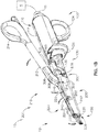
- FIGS. 1A-2 and FIGS. 13A-13C illustrate a first exemplary ultrasonic surgical instrument (10). At least part of instrument (10) may be constructed and operable in accordance with at least some of the teachings of U.S. Pat. No. 5,322,055 ; U.S. Pat. No. 5,873,873 ; U.S. Pat. No. 5,980,510 ; U.S. Pat. No. 6,325,811 ; U.S. Pat. No. 6,773,444 ; U.S. Pat. No. 6,783,524 ; U.S. Pub. No. 2006/0079874 ; U.S. Pub. No. 2007/0191713 ; U.S. Pub. No.
- At least part of instrument (10) may be constructed and operable in accordance with at least some of the teachings of U.S. Pub. No. 2017/0105755 , entitled “Surgical Instrument with Dual Mode End Effector and Compound Lever with Detents,” published on April 20, 2017; and/or U.S. Pat. App. No. 62/363,411 , entitled “Surgical Instrument with Dual Mode End Effector,” filed July 18,2016.
- instrument (10) is operable to cut tissue and seal or weld tissue (e.g., a blood vessel, etc.) substantially simultaneously. It should also be understood that instrument (10) may have various structural and functional similarities with the HARMONIC ACE® Ultrasonic Shears, the HARMONIC WAVE® Ultrasonic Shears, the HARMONIC FOCUS® Ultrasonic Shears, and/or the HARMONIC SYNERGY® Ultrasonic Blades. Furthermore, instrument (10) may have various structural and functional similarities with the devices taught in any of the other references that are cited.
- Instrument (10) in the present example includes a first modular assembly (100), a second modular assembly (200), and a coupling member (300).
- coupling member (300) may selectively attach first modular assembly (100) with second modular assembly (200) in order to form instrument (10) with an end effector (12).
- end effector (12) comprises an ultrasonic blade (150) and a clamp pad (222) of a clamp pad assembly (220).
- second modular assembly (200) may actuate relative to first modular assembly (100), when properly attached with each other, in order to actuate end effector (12) from an open configuration ( FIGS. 1A and 16A ), to a closed configuration ( FIGS. 1B and 16B ).
- the ability to selectively attach and detach second modular assembly (200) with first modular assembly (100) may provide additional benefits of reusability of either modular assembly (100, 200). For instance, different kinds of first modular assemblies (100) may be used with second modular assembly (200) to provide different kinds of surgical instruments. Similarly, different kinds of second modular assemblies (200) may be used with first modular assembly (100) to provide different kinds of surgical instruments. Additionally, moving components of second modular assembly (200) may be housed within static components of second modular assembly (200), which may provide additional advantages, some of which are described below while others will be apparent to one having ordinary skill in the art in view of the teachings herein.
- First modular assembly (100) includes a handle assembly (110), a shaft assembly (130) extending distally from handle assembly (110), and an ultrasonic blade (150) extending distally from shaft assembly (130).
- Handle assembly (110) includes a body (112), a finger grip ring (124), a pair of buttons (126) distal to finger grip ring (124), and an ultrasonic transducer assembly (30) housed within body (112).
- Shaft assembly (130) includes a proximal outer sheath (132) extending distally from body (112), a tube (138) extending distally from proximal outer sheath (132), and a waveguide (140) extending within and through both proximal outer sheath (132) and tube (138).
- Proximal outer sheath (132) includes a pair of protrusions (136). Additionally, proximal outer sheath (132) defines a pair of recesses (134).
- recesses (134) are dimensioned to mate with a portion of distal outer sheath (230) while protrusions (136) are configured to pivotally couple proximal outer sheath (132) with coupling member (300). Both recesses (134) and protrusions (136) may help couple first modular assembly (100) with coupling member (300).
- Proximal outer sheath (132) may be fixed relative to body (112), while tube (138) may be fixed relative to proximal outer sheath (132).
- waveguide (140) may attach to transducer assembly (30) and be supported by portions proximal outer sheath (132) and tube (138).
- Ultrasonic blade (150) may be unitarily connected to waveguide (140), and also extend distally from waveguide (140).
- waveguide (140) is operable to connect to ultrasonic transducer assembly (30) in order to provide acoustic communication between ultrasonic blade (150) and transducer assembly (30).
- ultrasonic transducer assembly (30) is housed within body (112) of handle assembly (110). As seen in FIGS. 1A-1B , transducer assembly (30) is coupled with a generator (5) via a plug (11). Transducer assembly (30) receives electrical power from generator (5) and converts that power into ultrasonic vibrations through piezoelectric principles.
- Generator (5) may include a power source and control module that is configured to provide a power profile to transducer assembly (30) that is particularly suited for the generation of ultrasonic vibrations through transducer assembly (30).
- Generator (5) may also be configured to provide a power profile that enables end effector (12) to apply RF electrosurgical energy to tissue.
- generator (5) may comprise a GEN 300 sold by Ethicon Endo-Surgery, Inc. of Cincinnati, Ohio.
- generator (not shown) may be constructed in accordance with at least some of the teachings of U.S. Pat. No. 8,986,302 , entitled “Surgical Generator for Ultrasonic and Electrosurgical Devices,” published April 14, 2011. It should also be understood that at least some of the functionality of generator (5) may be integrated into handle assembly (110), and that handle assembly (110) may even include a battery or other on-board power source such that plug (11) is omitted. Still other suitable forms that generator (5) may take, as well as various features and operabilities that generator (5) may provide, will be apparent to those of ordinary skill in the art in view of the teachings herein.
- Waveguide (140) Ultrasonic vibrations that are generated by transducer assembly (30) are communicated along acoustic waveguide (140) when properly coupled.
- Waveguide (140) is mechanically and acoustically coupled with transducer assembly (30).
- Waveguide (140) extends through shaft assembly (130) to reach ultrasonic blade (150).
- Waveguide (140) may be secured to proximal outer sheath (132) and/or body (112) via a pin (135) extending through waveguide (140) and proximal outer sheath (132). Pin (135) may help ensure waveguide (140) remains longitudinally and rotationally fixed relative to the rest of shaft assembly (130) when waveguide (140) is in a deactivated state (i.e. not vibrating ultrasonically).
- waveguide (140) may be supported by tube (138) via seals (142) located between an interior of tube (138) and an exterior of waveguide (140). Seals (142) may also prevent unwanted matter and fluid from entering portions of tube (138) housing waveguide (140). Pin (135) and seals (142) are located at positions along the length of waveguide (140) corresponding to nodes associated with resonant ultrasonic vibrations communicated through waveguide (140). Therefore, contact between waveguide (140) and pin (135), as well as contact between waveguide (140) and seals (142) may not affect ultrasonic vibrations communicated through waveguide (154).
- ultrasonic blade (150) When ultrasonic blade (150) is in an activated state (i.e., vibrating ultrasonically), ultrasonic blade (150) is operable to effectively cut through and seal tissue, particularly when the tissue is being clamped between clamp pad (222) and ultrasonic blade (150).
- waveguide (140) may be configured to amplify mechanical vibrations transmitted through waveguide (140).
- waveguide (140) may include features operable to control the gain of the longitudinal vibrations along waveguide (140) and/or features to tune waveguide (140) to the resonant frequency of the system.
- the distal end of ultrasonic blade (150) is located at a position corresponding to an anti-node associated with resonant ultrasonic vibrations communicated through waveguide (140), in order to tune the acoustic assembly to a preferred resonant frequency f o when the acoustic assembly is not loaded by tissue.
- the distal end of ultrasonic blade (150) is configured to move longitudinally in the range of, for example, approximately 10 to 500 microns peak-to-peak, and in some instances in the range of about 20 to about 200 microns at a predetermined vibratory frequency f o of, for example, 55.5 kHz.
- transducer assembly (30) of the present example When transducer assembly (30) of the present example is activated, these mechanical oscillations are transmitted through the waveguide to (140) reach ultrasonic blade (150), thereby providing oscillation of ultrasonic blade (150) at the resonant ultrasonic frequency.
- the ultrasonic oscillation of ultrasonic blade (150) may simultaneously sever the tissue and denature the proteins in adjacent tissue cells, thereby providing a coagulative effect with relatively little thermal spread.
- an electrical current may also be provided through ultrasonic blade (150) and/or clamp pad (222) to also seal the tissue.
- instrument (10) may also be configured to provide radiofrequency (RF) energy to a surgical site via end effector (12).
- RF radiofrequency
- an operator may rely mainly on the use of ultrasonic energy from blade (150) to sever tissue that is captured between ultrasonic blade (150) and clamp pad (222). The operator may further rely on the use of RF energy from end effector (12) to seal the severed tissue.
- the ultrasonic energy from blade (150) may seal tissue to some degree, such that the RF energy from end effector (12) may supplement the sealing that would already be provided from the ultrasonic energy.
- instrument (10) are capable of providing all of the above noted kinds of functionality.
- instrument (10) may be configured and operable to provide both ultrasonic and RF electrosurgical modes of operation are described in various references cited herein; while other ways in which instrument (10) may be configured and operable to provide both ultrasonic and RF electrosurgical modes of operation will be apparent to those of ordinary skill in the art in view of the teachings herein.
- buttons (126) may activate buttons (126) to selectively activate transducer assembly (30) to thereby activate ultrasonic blade (150).
- two buttons (126) are provided.
- one button (126) is provided for activating ultrasonic blade (150) at a first power profile (e.g., a first frequency and/or first amplitude) and another button (126) is provided for activating ultrasonic blade (150) at a second power profile (e.g., a second frequency and/or second amplitude).
- one button (126) is provided for activating ultrasonic blade (150) with ultrasonic energy
- the other button (126) is provided for activating end effector (12) with RF energy.
- one button (126) is operable to activate ultrasonic blade (150) with ultrasonic energy while simultaneously activating end effector (12) with RF energy; while the other button (126) is only operable to activate ultrasonic blade (150) with ultrasonic energy.
- at least one button (126) is operable to initially activate ultrasonic blade (150) with ultrasonic energy, then based on one or more other conditions (e.g., time, measured impedance, etc.) while button (126) remains activated, eventually activating end effector (12) with RF energy while still activating ultrasonic blade (150) with ultrasonic energy.
- At least one button (126) is operable to initially activate ultrasonic blade (150) with ultrasonic energy, then based on one or more other conditions (e.g., time, measured impedance, etc.) while button (126) remains activated, eventually activating end effector (12) with RF energy while ceasing activation of ultrasonic blade (150) with ultrasonic energy.
- at least one button (126) is operable to initially activate end effector (12) with RF energy, then based on one or more other conditions (e.g., time, measured impedance, etc.) while button (126) remains activated, eventually activating ultrasonic blade (150) with ultrasonic energy while ceasing activation of end effector (12) with RF energy.
- buttons and/or otherwise selectable power levels and/or power modalities may be provided.
- a foot pedal may be provided to selectively activate transducer assembly (30).
- Buttons (126) of the present example are positioned such that an operator may readily fully operate instrument (10) with a single hand. For instance, when first and second modular assemblies (100, 200) are coupled, the operator may position their thumb in thumb grip ring (214), position their ring finger in finger grip ring (124), position their middle finger about body (112), and manipulate buttons (126) using their index finger. Of course, any other suitable techniques may be used to grip and operate instrument (10); and buttons (126) may be located at any other suitable positions.
- coupling member (300) is configured to selectively couple first modular assembly (100) with second modular assembly (200).
- coupling member (300) comprises a body (302), a pair of resilient arms (304) extending from body (302), and a pair of grips (305) extending from body (302).
- Resilient arms (304) each define a respective pivot bore (306) and locking assembly (308).
- Resilient arms (304) are spaced apart from each other in order to receive proximal outer sheath (132) and to snap-fit pivot bores (306) with respective protrusions (136). Therefore, as shown between FIGS.
- coupling member (300) is configured to pivotally connect with proximal outer sheath (132) via pivot bores (306) and protrusions (136). While in the current example, coupling member (300) and proximal outer sheath (132) are pivotally coupled via snap-fitting, any other type of suitable connection may be used as would be apparent to one having ordinary skill in the art in view of the teachings herein.
- protrusions (136) may be extendable relative to proximal outer sheath (132) in order to pivotally couple with pivot bore (306) of coupling member (300).
- Grips (305) may be positioned on body (302) such that an operator may easily rotate coupling member (300) relative to outer sheath (132) via grips (305).
- Each locking assembly (308) includes an interior contact wall (310) facing toward each other and a coupling recess (312). As will be described in greater detail below, locking assembly (308) is configured to rotate about pivot bore (306) and protrusions (136) in order to selectively couple with portions of second modular assembly (200).
- coupling member (300) in the current example is used to connect first modular assembly (100) with second modular assembly (200), it should be understood that coupling member (300) may be incorporated into any suitable type of modular assembly that would be apparent to one having ordinary skill in the art in view of the teachings herein.
- coupling assembly (300) may be modified to couple different modular clamp arm assemblies with first modular assembly (100) where the different modular clamp arm assemblies include clamp arm assemblies such as those taught in U.S. Pub. No. 2017/0105788 , entitled "Surgical Instrument with Dual Mode End Effector and Modular Clamp Arm Assembly," published on April 20, 2017.
- one modular clamp arm assembly that may be coupled with first modular assembly (100) may provide pivotal motion of a clamp arm at one side of ultrasonic blade (150) while the other modular clamp arm assembly that may be coupled with first modular assembly (100) may provide pivotal motion of a clamp arm at the other side of ultrasonic blade (150).
- Other suitable kinds of clamp arm assemblies that may be used to provide different kinds of second modular assemblies (200) will be apparent to those of ordinary skill in the art in view of the teachings herein.
- Second modular assembly (200) includes a clamp arm assembly (210), a clamp pad assembly (220), and a distal outer sheath (230).
- distal outer sheath (230) is configured to couple with both coupling member (300) and proximal outer sheath (132) in order to selectively couple first modular assembly (100) with second modular assembly (200). It other words, when properly coupled, proximal outer sheath (132) and distal outer sheath (230) may be fixed relative to one another.
- clamp arm assembly (210) and clamp pad assembly (220) are both pivotally coupled with distal outer sheath (230).
- clamp arm assembly (210) and clamp pad assembly (220) are dimensioned to mesh with each other such that rotation of one assembly (210, 220) relative to distal outer sheath (230) causes rotation of the other assembly (210, 220) relative to distal outer sheath (230).
- clamp arm assembly (210) and clamp pad assembly (220) are capable of rotating each other relative to distal outer sheath (230).
- Distal outer sheath (230) includes a U-shaped body (232) extending from a distal face (235) and terminating in a pair of proximally presented projections (234).
- Proximally presented projections (234) each include a lateral protrusion (238) extending away from U-shaped body (232).
- U-shaped body (232) defines a longitudinal pathway (236) and a plurality of bores (240).
- U-shaped body (232) and longitudinal pathway (236) are dimensioned to receive tube (138) and to rotationally house a portion of clamp arm assembly (210) and clamp pad assembly (220). In particular, as best shown between FIGS.
- U-shaped body (232) may be inserted over ultrasonic blade (150) and tube (138) such that tube (138) will rest under clamp arm assembly (210) and clamp pad assembly (220).
- Tube (138) may protect waveguide (140) such that clamp arm assembly (210) and clamp pad assembly (220) do not contact adjacent portions of waveguide (140).
- proximally presented projections (234) are configured to be inserted into recesses (134) defined by proximal outer sheath (132).
- proximally presented projections (234) When proximally presented projections (234) are inserted into recesses (134), distal outer sheath (230) may not rotate relative to proximal outer sheath (132) about a longitudinal axis defined by tube (138). Therefore, proximally presented projections (234) may mate with recesses (134) in order to rotationally fix distal outer sheath (230) relative to proximal outer sheath (132).
- an operator may rotate coupling member (300) such that locking assembly (308) snap-fits with lateral protrusions (238).
- an operator may rotate coupling member (300) about protrusion (136) such that lateral protrusions (238) cam against contact walls (310) of resilient arms (304).
- contact between contact walls (310) and lateral protrusions (238) flex resilient arms (304) outwardly away from proximally presented projections (234).
- An operator may further rotate coupling member (300) about protrusions (136) such that lateral protrusions (238) no longer abut against contact wall (310), as shown in FIGS. 13C , 14C , and 15C .
- the resilient nature of resilient arms (304) allows resilient arms (304) to return to a relaxed position such that lateral protrusions (238) rest within coupling recess (312) of locking assembly (308).
- first modular assembly (100) may be decoupled with second modular assembly (200)
- an operator may grasp grips (305) to rotate coupling member (300) in the opposite direction about protrusions (136) in order to flex resilient arms (304) to pop out lateral protrusions (238) from coupling recess (312).
- clamp arm assembly (210) and clamp pad assembly (220) are both pivotally coupled with distal outer sheath (230) such that rotation of one assembly (210, 220) relative to distal outer sheath (230) causes rotation of the other assembly (210, 220) relative to distal outer sheath (230).
- Clamp arm assembly (210) includes an elongated arm (212), a thumb grip ring (214), a camming protrusion (216), and a pivot coupling (218).
- Thumb grip ring (214) and elongated arm (212) together provide a scissor grip type configuration in combination with body (112) and finger grip ring (124).
- Pivot coupling (218) pivotally couples clamp arm assembly (210) with distal outer sheath (230) via pins (202).
- camming protrusion (216) interacts with clamp pad assembly (220) in order to rotate clamp pad assembly (220) in response to rotation of clamp arm assembly (210).
- Clamp pad assembly (220) includes a clamp pad (222) facing ultrasonic blade (150), a pair of tissue stops (223) located adjacent to ultrasonic blade (150) and proximal to clamp pad (222), an arm (224) defining both a camming recess (226) and a spring recess (221), a pivot coupling (228), and a leaf spring (225) housed within spring recess (221).
- clamp pad assembly (220) further includes one or more electrodes that is/are operable to apply RF electrosurgical energy to tissue.
- clamp pad assembly may incorporate one or more electrodes that is/are operable to apply RF electrosurgical energy to tissue
- clamp pad assembly (220) may incorporate one or more electrodes that is/are operable to apply RF electrosurgical energy to tissue
- tissue stops (223) longitudinally align with distal face (235) when end effector (12) is in the closed position. Tissue stops (223) and distal face (235) may cooperate to consistently and simply prevent tissue from inadvertently reaching a proximal position within end effector (12) where ultrasonic energy from blade (150) may not adequately sever or seal the tissue. In providing such prevention, tissue stop (223) may eliminate the need for an operator to visualize proximal region of end effector (12) in order to determine whether the tissue has reached an undesirably proximal position within end effector (12).
- Camming protrusion (216) is dimensioned to rotate within camming recess (226) while also contacting camming recess (226). Camming protrusion (216) and camming recess (226) are positioned within distal outer sheath (230) such that both are located between pivot couplings (218, 228) while clamp arm assembly (210) and clamp pad assembly (220) are pivotally coupled to distal outer sheath (230). Therefore, as shown between FIGS. 1A-1B and 16A-16B , when an operator rotates elongated arm (212) about pivot coupling (218) toward distal outer sheath (230), camming protrusion (216) rotates away from distal outer sheath (230) about pivot coupling (218).
- camming protrusion (216) is housed within camming recess (226)
- upward movement of camming protrusion (216) about pivot coupling (218) causes upward movement of camming recess (226) about pivot coupling (228).
- Upward movement of camming recess (226) about pivot coupling (228) rotates arm (224) such that clamp pad (222) rotates toward ultrasonic blade (150). Therefore, closure of elongated arm (212) of clamp arm assembly (210) toward handle assembly (110) leads to closure of clamp pad (222) toward ultrasonic blade (150).
- first modular assembly (100) and second modular assembly (200) are connected, an operator may squeeze thumb grip ring (214) toward body (112) to thereby clamp tissue between clamp pad assembly (220) and ultrasonic blade (150) to compress tissue against ultrasonic blade (150).
- thumb grip ring (214) toward body (112) to thereby clamp tissue between clamp pad assembly (220) and ultrasonic blade (150) to compress tissue against ultrasonic blade (150).
- ultrasonic blade (150) When ultrasonic blade (150) is activated during such compression, clamp pad assembly (220) and ultrasonic blade (150) cooperate to transect and/or seal the compressed tissue.
- leaf spring (225) is housed within spring recess (221). As best seen in FIGS.16A-16B , leaf spring (225) is dimensioned such that a portion of leaf spring (225) extends out of spring recess (221) to make contact against tube (138) in order to provide electrical continuity between the one or more RF electrodes of end effector (12) and the source of electrical power. It should be understood that leaf spring (225) maintains this electrical continuity throughout the range of motion of clamp pad assembly (220). It should also be understood that any other suitable kinds of features may be used to provide electrical continuity between the one or more RF electrodes of end effector (12) and the source of electrical power.
- one or more resilient members are used to bias clamp pad assembly (220) toward the open position shown in FIGS. 1A and 16A .
- any other suitable kind of resilient member may be used as would be apparent to one having ordinary skill in the art in view of the teachings herein, such as a torsion spring.
- clamp pad assembly (220) need not necessarily be biased toward the open position.
- Pivot couplings (218, 228) of clamp arm assembly (210) and clamp pad assembly (220) being located within longitudinal pathway (236) of distal outer sheath (230) may provide certain desirable advantages as compared to clamp arm assembly (210) and clamp pad assembly (220) pivotally coupling with an exterior of distal outer sheath (230). For instance, there may be a reduced chance of inadvertently pinching tissue due to rotation of clamp arm assembly (210) and clamp pad assembly (220) with pivot couplings (218, 228) being housed within U-shaped body (232). In other words, U-shaped body (232) may protect tissue from being inadvertently pinched by rotation of clamp arm assembly (210) and clamp pad assembly (220) relative to distal outer sheath (230).
- second modular assembly (200) may be reduced due to pivot couplings (218, 228) being housed within longitudinal pathway (236) of distal outer sheath (230). It may also be easier to fabricate desired components due to the simplified shapes of clamp arm assembly (210) and clamp pad assembly (220). A reduction of tolerance stack may also be an advantage to storing pivot couplings (218, 228) within the interior of distal outer sheath (230).
- instrument (10) may be configured in numerous other ways as will be apparent to those of ordinary skill in the art in view of the teachings herein.
- at least part of instrument (10) may be constructed and/or operable in accordance with at least some of the teachings of any of the following: U.S. Pat. No. 5,322,055 ; U.S. Pat. No. 5,873,873 ; U.S. Pat. No. 5,980,510 ; U.S. Pat. No. 6,325,811 ; U.S. Pat. No. 6,783,524 ; U.S. Pub. No. 2006/0079874 ; U.S. Pub. No.
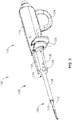
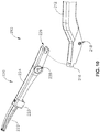
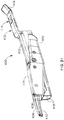
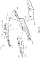
- FIGS. 17-18 show a second exemplary ultrasonic surgical instrument (301). Except as otherwise described below, instrument (301) of this example may be constructed and operable just like instrument (10) described above. Certain details of instrument (301) will therefore be omitted from the following description, it being understood that such details are already provided above in the description of instrument (10).
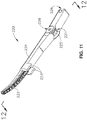
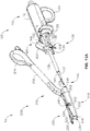
- Instrument (301) of the present example comprises a handle assembly (311), a clamp arm actuator (320), a shaft assembly (330), and a clamp arm assembly (400).
- Handle assembly (311) of this example is configured and operable just like handle assembly (110) described above, such that details of handle assembly (311) will not be reiterated here.
- Clamp arm actuator (320) is pivotably coupled with shaft assembly (330).
- clamp arm actuator (320) is not removable from shaft assembly (330).
- Clamp arm actuator (320) of the present example comprises a shaft (322).
- a thumb ring (324) is positioned at the proximal end of shaft (322).
- pair of projections (326) extend distally from shaft (322). Projections (326) are laterally spaced apart from each other and extend parallel to each other.
- the distal end of each projection (326) includes a camming protrusion (328).
- Camming protrusions (328) are configured to cooperate with clamp arm assembly (400), in a manner similar to camming protrusions (216), as will be described below.
- projections (326) also define a pair of pin openings (327), which are configured to receive pin (338).
- Pin (338) provides a pivotable coupling between clamp arm actuator (320) and shaft assembly (330).
- Shaft assembly (330) extends distally from handle assembly (311) and is substantially identical to shaft assembly (130) described above except for the differences described below.
- An ultrasonic blade (350) which is identical to ultrasonic blade (150) described above, is positioned at the distal end of shaft assembly (130).
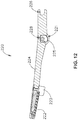
- shaft assembly (330) defines an opening (332) that is configured to receive pin (338) to thereby provide a pivotable coupling between clamp arm actuator (320) and shaft assembly (330).
- shaft assembly (330) includes a ramped latch protrusion (334), which is configured to engage clamp arm assembly (400) as will be described in greater detail below.
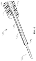
- clamp arm assembly (400) of the present example comprises a pair of shrouds (402, 404) partially encompassing a clamp arm body (430), which is pivotally coupled with a stationary body (410).
- Each shroud includes a distally presented tissue stop edge (408).
- Stationary body (410) also includes a pair of distally presented tissue stop edges (418).
- Edges (408, 418) are configured to cooperate to consistently and restrict proximal positioning of tissue like tissue stops (223) and distal face (235) described above.
- Shroud (404) of the present example also includes a distally projecting shield member (406).
- Stationary body (410) of the present example further includes a pin opening (411) and a proximally projecting latch member (412).
- Latch member (412) defines a latch opening (414) and a ramp (416).
- Latch member (412) is configured to cooperate with latch protrusion (334) of shaft assembly (330) to selectively secure clamp arm assembly (400) to shaft assembly (330).
- an operator may align clamp arm assembly (400) with shaft assembly (330) along a common axis, and then insert blade (350) and the remaining distal portion of shaft assembly (330) into clamp arm assembly (400).
- Ramp (416) will eventually engage latch protrusion (334), which will provide a camming action that causes latch member (412) to deflect away from the longitudinal axis.
- latch protrusion (334) eventually reaches latch opening (414), at which point latch member (412) resiliently returns to a straight, non-deflected state.
- latch protrusion (334) is disposed in latch opening (414) and thereby secures clamp arm assembly (400) to shaft assembly (330).
- clamp arm assembly (400) When the operator wishes to remove clamp arm assembly (400) from shaft assembly (330), the operator may simply engage ramp (416) and thereby urge latch member (412) to a deflected state where latch member (412) can clear latch protrusion (334); then pull clamp arm assembly (400) away from shaft assembly (330).
- ramp (416) When the operator wishes to remove clamp arm assembly (400) from shaft assembly (330), the operator may simply engage ramp (416) and thereby urge latch member (412) to a deflected state where latch member (412) can clear latch protrusion (334); then pull clamp arm assembly (400) away from shaft assembly (330).
- Other suitable structures and techniques that may be used to secure clamp arm assembly (400) to shaft assembly (330), and to remove clamp arm assembly (400) from shaft assembly (330), will be apparent to those of ordinary skill in the art in view of the teachings herein.
- Clamp arm body (430) of the present example comprises a clamp pad (432) and a pair of proximal projections (434).
- Clamp pad (432) is positioned and configured to compress tissue against ultrasonic blade (350) when clamp arm assembly (400) is secured to shaft assembly (330).
- Shield member (406) of shroud (404) is configured to extend over the exterior of the distal end of clamp arm body (430), without covering clamp pad (432). Shield member (406) thus enables clamp pad (432) to contact tissue directly.
- Projections (438) each comprise a respective proximally presented recess (436) and a pair of pin openings (438).
- a pin (440) is positioned in pin openings (411, 438) to thereby pivotally couple clamp arm body (430) with stationary body (410).
- Shrouds (402, 404) are fixedly secured to clamp arm body (430) such that shrouds (402, 404) pivot with clamp arm body (430) relative to stationary body (410).
- recesses (436) have a generally U-shaped configuration. Recesses (436) are configured to receive camming protrusions (328) of clamp arm actuator (320).
- camming protrusions (328) will enter recesses (436) when latch member (412) reaches the point at which latch member (412) secures clamp arm assembly (400) to shaft assembly (330).
- camming protrusions (328) may freely exit recesses (436), as clamp arm actuator (320) remains secured to shaft assembly (330). As best seen in FIG.
- shrouds (402, 404) are configured to cover the interfaces between recesses (436) and camming protrusions (328). It should be understood that the relationship between recesses (436) and camming protrusions (328) is substantially identical to the relationship between camming protrusion (216) and camming recess (226) described above. Thus, recesses (436) and camming protrusions (328) provide a pivoting coupling between clamp arm body (430) and clamp arm actuator (320).
- clamp arm actuator (320) is pivotally coupled with shaft assembly (330) via pin (338); and clamp arm body (430) is pivotally coupled with stationary body (410) via pin (440); while stationary body (410) is fixedly secured to shaft assembly (330).
- the pivoting interface between recesses (436) and camming protrusions (328) is longitudinally positioned between the longitudinal positions of pins (338, 440). It should therefore be understood that clamp arm actuator (320) and clamp arm body (430) cooperate to provide a compound lever assembly. When an operator pivots thumb ring (324) toward handle assembly (311), the compound lever action provides corresponding pivotal movement of clamp pad (432) toward ultrasonic blade (350).
- a resilient beam (313) is secured to clamp arm actuator (320) and slidably bears against shaft assembly (330), such that resilient beam (313) resiliently urges clamp arm actuator (320) away from handle assembly (311).
- resilient beam (313) will urge thumb ring (324) away from handle assembly (311), thereby urging clamp pad (432) away from ultrasonic blade (350).
- any other suitable components and arrangements may be used to provide a resilient bias to clamp arm actuator (320).
- such resilient bias may simply be omitted.
- waveguide (140) may be supported by tube (138) via seals (142) located between an interior of tube (138) and an exterior of waveguide (140). Seals (142) may also prevent unwanted matter and fluid from entering portions of tube (138) housing waveguide (140).
- the most distal seal (142) is manually placed onto waveguide (140) such as by rolling seal (142) onto waveguide (140) after passing ultrasonic blade (15) through seal (142). This manual manipulation and placement of seal (142) may degrade the material of seal (142), leading to either early degradation of seal (142) or even an unsealed fit between waveguide (140) and seal (142).
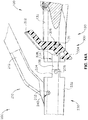
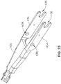
- FIGS. 24-28E illustrate a third exemplary surgical instrument (9300), similar to instrument (10), with like elements having like numbering.
- instrument (9300) rather than physically applying an o-ring style seal such as seal (142) onto waveguide (140), instrument (9300) include a seal (9302) molded directly onto waveguide (140).
- seal (9302) is overmolded onto waveguide (140) in situ to allow the material of seal (9302) to bond with both the exterior of waveguide (140) and the interior of tube (138), thus creating a tight-fitting seal therebetween to prevent unwanted matter and fluid from entering tube (138).
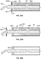
- tube (138) and waveguide (140) define a cavity (9304) therebetween.
- a form (9306) is assembled within cavity (9304) to overmold seal (9302) in situ to tube (138) and waveguide (140).
- Form (9306) includes a proximal form portion (9308) and a distal form portion (9310) which may be brought together to define a mold space (9312) therebetween.
- Proximal form portion (9308) is an elongated tamper style device which enters cavity (9304) from the proximal end of tube (138).
- Proximal form portion (9308) includes a shutoff portion (9314) which generally matches the space between tube (138) and waveguide (140) in order to prevent the seal forming material from expanding past proximal form portion (9308).
- Proximal form portion (9308) further includes a sleeve portion (9316) which may be flexible to adjust to the contours or angles of tube (138).
- a user or machine extends proximal form portion (9308) into cavity (9304) in the direction of Arrow (9300A) by manipulating sleeve portion (9316) to extend shutoff portion (9314) to the proper placement within tube (138).
- shutoff portion (9314) is configured to prevent any seal forming material from moving beyond shutoff portion (9314) and into the proximal area of tube (138).
- Distal form potion (9310) is a capping style device, a portion of which is configured to enter into cavity (9304) from the distal end of tube (138).
- Distal form portion (9310) includes an internal portion (9318) and an external portion (9320). Internal portion (9318) is configured to extend into cavity (9304), while external portion (9320) is configured to abut the outermost end of tube (138).
- Distal form portion (9310) also defines an internal channel (9322), which is sized to fit waveguide (140) therein.
- a user or machine extends distal form portion (9310) over waveguide (140) in the direction of Arrow (9300B), with waveguide (140) disposed within internal channel (9322) and until external portion (9320) abuts the outer end of tube (138). This orients internal portion (9318) in cavity (9304), distal to proximal form portion (9308). As distal form portion (9310) is pressed against tube (138), form (9306) is created and mold space (9312) is defined.
- distal form portion (9310) defines a material channel (9324).
- Material channel (9324) extends from the exterior of external portion (9320) to the exterior of internal portion (9322).
- Material channel (9324) allows material used in forming seal (9302) to travel through distal form portion (9310) in the direction of Arrow (9300C) and into mold space (9312) while distal form portion (9310) is held against tube (138). This allows seal (9302) to be formed through distal form portion (9310) while distal form portion (9310) is coupled with tube (138).
- seal (9302) is allowed to set and/or cure. After seal (9302) is sufficiently cured, both proximal form portion (9308) and distal form portion (9310) are removed from tube (138), leaving seal (9302) adhered to both tube (138) and waveguide (140) to prevent liquid and debris from entering cavity (9304).
- seal (9302) is located at a position along the length of waveguide (140) corresponding to a node associated with resonant ultrasonic vibrations communicated through waveguide (140). Therefore, contact between waveguide (140) and seal (9302) may not affect ultrasonic vibrations communicated through waveguide (140).
- distal outer sheath (230) is configured to reduce the likelihood of inadvertently pinching tissue due to rotation of clamp arm assembly (210) and clamp pad assembly (220) and may thus protect tissue. While such protection may be beneficial to the patient in some instances, distal outer sheath (230) also inhibits access within surgical instrument (10) and, more particular, access about tube (138) and ultrasonic blade (150). In some uses, blood and other bodily fluids and tissues may travel proximally along ultrasonic blade and about tube (138), thus hindering cleaning and effective sterilization of one or more portions of surgical instrument (10) for reuse.
- surgical instrument (10) or any such instrument as those described herein, with an accessible outer sheath (9612, 9712, 9812, 9912, 10012) configured to provide access within surgical instrument (10) for cleaning and, more particularly, sterilizing, surgical instrument (10).
- an accessible outer sheath 9612, 9712, 9812, 9912, 10012
- alternative access for uses other than cleaning may similarly be performed.
- the invention is thus not intended to be unnecessarily limited to use for cleaning.
- accessible outer sheaths (9612, 9712, 9812, 9912, 10012) are shown in distinct positions with distinct securements (9620, 9720, 9820, 9920, 10020), it will be appreciated that accessible outer sheaths (9612, 9712, 9812, 9912, 10012) with one or more securements (9620, 9720, 9820, 9920, 10020) may be incorporated into any surgical instrument described herein, exchanged, or moved so as to make one or more portions of outer sheaths detachable from a remainder of the surgical instrument. To this end, like reference numeral indicate like features.
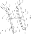
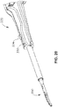
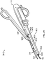
- FIGS. 29-35C illustrate a fourth exemplary surgical instrument (9610) including a shaft assembly (9611) with a first accessible outer sheath (9612).
- Surgical instrument (9610) further includes handle assembly (110), clamp arm assembly (210) with clamp pad assembly (220), clamp arm actuator (320), and tube (138) through which waveguide (140) extends to ultrasonic blade (150) along the longitudinal axis.
- accessible outer sheath (9612) radially surrounds at least a portion of waveguide (140) about the longitudinal axis and includes a sheath body (9616), a hinge cover (9618), and a sheath securement (9620).
- Sheath body (9616) removably receives hinge cover (9618) thereagainst to define a generally U-shape, and sheath securement (9620) detachably couples hinge cover (9618) against sheath body (9616).
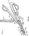
- hinge cover (9618) generally remains in a covered configuration as shown in FIG. 29 .
- the clinician selectively detaches hinge cover (9618) from sheath body (9616) as shown in FIGS. 30-31 for accessing an inner portion (9622) of surgical instrument (9610) about tube (138) as desired, such as for more easily cleaning and/or sterilizing inner portion (9622) following treatment of the patient.
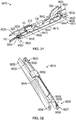
- FIG. 31 and FIG. 32 show sheath body (9616), hinge cover (9618), and sheath securement (9620) in greater detail.
- sheath securement (9620) includes a distal securement (9624) having a snap coupling (9625) and a proximal securement (9626) having a hinge coupling (9627).
- Snap coupling (9625) includes a pair of offset elongated resilient tabs (9628) configured to releasably engage a pair of shoulders (9630), respectively.
- each elongated tab (9628) extends from hinge cover (9618), whereas shoulders (9630) are positioned on sheath body (9616).
- elongated tabs (9628) distally extend relative to a laterally extending buttress (9632), which provides structural support through hinge cover (9618).
- Hinge coupling (9627) of proximal securement (9626) includes a pair of laterally extending and opposing pins (9634) configured to be pivotally received within a pair of bores (9636), respectively.
- each pin (9635) extends laterally outward from sheath body (9616), whereas each bore (9636) extends through hinge cover (9618).
- Hinge cover (9618) generally pivots about pins (9635) relative to sheath body (9616), but is also fully removable from sheath body (9616) upon over rotation of hinge cover (9618) in the proximal direction.
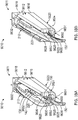
- a slot (9638) extends through an inner surface of hinge cover (9618) to each bore (9636).
- a distal mount (9640) and a proximal mount (9642) extend upward from each lateral side of sheath body (9612) adjacent to tube (138) within inner portion (9622).
- Distal and proximal mounts (9640, 9642) each have a lateral hole (9644) extending therethrough in order to pivotally mount clamp arm assembly (210) and clamp arm actuator (320) thereto.
- Hinge cover (9618) has a pair of distal mount recesses (9646) and a pair of proximal mount recesses (9648) configured to provide clearance for distal and proximal mounts (9640, 9642) along an inner surface of hinge cover (9618).
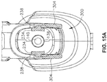
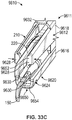
- FIGS. 33A-33B show a distal tissue stop (9650) configured to inhibit tissue from being proximally introduced into inner portion (9622) of surgical instrument (9610) beyond distal tissue stop (9650).
- an upper portion (9652) of distal tissue stop (9650) is a distal face of hinge cover (9618), whereas a lower portion (9654) of distal tissue stop (9650) is a distal face of sheath body (9616).
- Clamp pad assembly (220) is movably received within a clamp channel (9656) between lateral portions of distal tissue stop (9660) to thereby provide ample clearance to move clamp pad assembly (220) between open and closed positions as discussed above in greater detail.
- clinician accesses inner portion (9622) of surgical instrument (9610) by detaching hinge cover (9618) from sheath body (9616). More particularly, clinician selectively manipulates elongated tabs (9628) inward as shown in FIG. 33C through clamp channel (9656) until transversely clear of and disengaged from shoulders (9630). Once proximal securement (9626) is thereby disengaged, hinge cover (9618) proximally pivots from a longitudinal orientation to a transverse orientation as shown in FIGS. 34A-34B . Pins (9634) generally remain within bores (9636) during rotation from the longitudinal orientation of the covered configuration to the transverse orientation. However, as shown in FIGS.
- hinge cover (9618) over rotation of hinge cover (9618) proximally beyond the transverse orientation aligns slots (9638) respectively with pins (9634) such that hinge cover (9618) may be selectively removed from sheath body (9616) for accessing inner portion (9622).
- the clinician cleans surgical instrument (9610) using any one or more known cleaning methods for such instruments.
- clinician reattaches hinge cover (9618) in generally the reverse order of detaching hinge cover (9618) as described above.
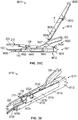
- FIGS. 36-39B illustrate a fifth exemplary surgical instrument (9710) including a shaft assembly (9711) with a second accessible outer sheath (9712).
- accessible outer sheath (9712) radially surrounds at least a portion of waveguide (140) about the longitudinal axis and includes a sheath body (9716), a magnetic cover (9718), and a sheath securement (9720).
- Sheath body (9716) removably receives magnetic cover (9718) thereagainst to define a generally U-shape, and sheath securement (9720) detachably couples magnetic cover (9718) against sheath body (9716).
- magnetic cover (9718) generally remains in a covered configuration as shown in FIG. 36 .
- the clinician selectively detaches magnetic cover (9718) from sheath body (9716) as shown in FIG. 37 for accessing an inner portion (9722) of surgical instrument (9710) about tube (138) as desired, such as for more easily cleaning and/or sterilizing inner portion (9722) following treatment of the patient.
- FIGS. 36-38 show sheath body (9716), magnetic cover (9718), and sheath securement (9720) in greater detail.
- sheath securement (9720) includes a distal securement (9724) having a distal magnetic coupling (9725) and a proximal securement (9726) having a proximal magnetic coupling (9727).
- Distal magnetic coupling (9725) includes a magnetically attractive base (9728) secured to clamp arm assembly (210) and a magnetic coupler, such as a disc magnet (9730), configured to a positioned opposite of base (9728). Thereby, disc magnet (9730), while magnetically attracted to base (9728) in proximity of base (9728) sandwiches magnetic cover (9718) therebetween.
- Magnetic cover (9718) further includes a cylindrical recess (9732) configured to receive disc magnet (9730) to both increase magnetic attraction of disc magnet (9730) to base (9728) as well as position disc magnet (9730) relatively flush with an outer surface thereon.
- disc magnet (9730) is fixed within cylindrical recess (9732) and base (9728) is a metallic material configured to attract disc magnet (9730).
- base (9728) may be magnetic for increased securement with disc magnet (9730).
- Proximal magnetic coupling (9727) of proximal securement (9726) includes an inner magnet (9734) secured to an inner surface of magnetic cover (9718) and extending inward toward tube (138).
- Tube (138) is magnetically attractive such that inner magnet (9734) is configured to engage tube (138) for removably coupling magnetic cover (9718) to tube (138).
- tube (138) is a metallic material configured to attract inner magnet (9734).
- tube (138) may be magnetic or having a magnet thereon for increased securement with inner magnet (9734).
- distal mount (9640) see FIG. 31
- proximal mount (9642) see FIG. 31
- distal and proximal mounts (9640, 9642) are generally similar to those discussed above. However, rather than having such mounts (9640, 9642) ( see FIG. 31 ) on each lateral side, mounts (9640, 9642) (see FIG. 31 ) are on the one side opposite from magnetic cover (9718) to thereby pivotally support clamp arm assembly (210) and clamp arm actuator (320) for use.
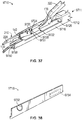
- FIG. 39A shows a distal tissue stop (9750) configured to inhibit tissue from being proximally introduced into inner portion (9722) of surgical instrument (9710) beyond distal tissue stop (9750).
- distal tissue stop (9750) is a distal face of sheath body (9716).
- Clamp pad assembly (220) is movably received within a clamp channel (9756) between lateral portions of distal tissue stop (9760) to thereby provide ample clearance to move clamp pad assembly (220) between open and closed positions as discussed above in greater detail.
- clinician accesses inner portion (9722) of surgical instrument (9710) by detaching magnetic cover (9718) from sheath body (9716). More particularly, clinician outwardly pulls on magnetic cover (9718) with sufficient force to overcome the magnetic attraction between disc magnet (9730) and base (9728) as well as between inner magnet (9734) and tube (138). Once distal and proximal securements (9724, 9726) are thereby disengaged, magnetic cover (9718) is simply removed from sheath body (9716) for accessing inner portion (9722). The clinician cleans surgical instrument (9710) using any one or more known cleaning methods for such instruments. Upon desirable cleaning, clinician reattaches magnetic cover (9718) in generally the reverse order of detaching magnetic cover (9718) as described above. In addition, clinician sterilizes surgical instrument (9710) following reattachment of magnetic cover (9718).
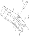
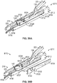
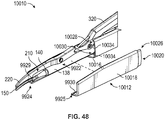
- FIGS. 40-41 illustrate a sixth exemplary surgical instrument (9810) including a shaft assembly (9811) with a third accessible outer sheath (9812).
- Accessible outer sheath (9812) radially surrounds at least a portion of waveguide (140) about the longitudinal axis and includes a sheath body (9816), a pin cover (9818), and a sheath securement (9820).
- Sheath body (9816) removably receives pin cover (9818) thereagainst to define a generally U-shape, and sheath securement (9820) detachably couples pin cover (9818) against sheath body (9816).
- pin cover (9818) generally remains in a covered configuration as shown in FIG.
- the clinician selectively detaches pin cover (9818) from sheath body (9816) as shown in FIG. 41 for accessing an inner portion (9822) of surgical instrument (9810) about tube (138) as desired, such as for more easily cleaning and/or sterilizing inner portion (9822) following treatment of the patient.
- Sheath securement (9820) includes a distal securement (9824) having a lower pin coupling (9825) and a proximal securement (9826) having another lower pin coupling (9825) and an upper pin coupling (9827).
- Each of lower and upper pin coupling (9825, 9827) includes a pin hole (9828) extending laterally through a mounting flange (9829) and a pin (9830). More particularly, sheath body (9816) and pin cover (9818) have a pair of cooperating pin holes (9828) through mounting flange (9829) for each lower and upper pin coupling (9825, 9827).
- Pin (9838) is configured to be received the cooperating pair of pin holes (9828) while coaxially aligned for removably attaching pin cover (9818) to sheath body (9816).
- pin (9838) is configured to frictionally engaged mounting flange (9829) within pin hole (9828) for securement.
- engagement such as other fasteners, may be similarly used. The invention is thus not intended to be unnecessarily limited to frictionally engaged pins (9830).
- distal mount (9640) see FIG. 31
- proximal mount (9642) see FIG. 31
- distal and proximal mounts (9640, 9642) are generally similar to those discussed above. However, rather than have such mounts (9640, 9642) ( see FIG. 31 ) on each lateral side, mounts (9640, 9642) ( see FIG. 31 ) are on the one side opposite from pin cover (9818) to thereby pivotally support clamp arm assembly (210) and clamp arm actuator (320) for use.
- Accessible outer sheath (9812) also has a distal tissue stop (9850) configured to inhibit tissue from being proximally introduced into inner portion (9822) of surgical instrument (9810) beyond distal tissue stop (9850).
- one lateral portion (9852) of distal tissue stop (9850) is a distal face of pin cover (9818), whereas another lateral portion (9854) of distal tissue stop (9850) is a distal face of sheath body (9816).
- Clamp pad assembly (220) is movably received within a clamp channel (9856) between lateral portions (9852, 9854) of distal tissue stop (9860) to thereby provide ample clearance to move clamp pad assembly (220) between open and closed positions as discussed above in greater detail.
- clinician accesses inner portion (9822) of surgical instrument (9810) by detaching pin cover (9818) from sheath body (9816). More particularly, clinician selectively withdraws pins (9830) from each pin hole (9828) for each of distal and proximal securements (9824, 9826). Once distal and proximal securements (9825, 9826) are thereby disengaged, pin cover (9818) is simply removed from sheath body (9816) for accessing inner portion (9822). The clinician cleans surgical instrument (9810) using any one or more known cleaning methods for such instruments. Upon desirable cleaning, clinician reattaches pin cover (9818) in generally the reverse order of detaching pin cover (9818) as described above. In addition, clinician sterilizes surgical instrument (9810) following reattachment of pin cover (9818).
- FIGS. 42-46 illustrate a seventh exemplary surgical instrument (9910) including a shaft assembly (9911) with a fourth accessible outer sheath (9912).
- accessible outer sheath (9912) radially surrounds at least a portion of waveguide (140) about the longitudinal axis and includes a sheath body (9916), a first snap cover (9918), and a sheath securement (9920).
- Sheath body (9916) removably receives snap cover (9918) thereagainst to define a generally U-shape, and sheath securement (9920) detachably couples snap cover (9918) against sheath body (9916).
- snap cover (9918) generally remains in a covered configuration as shown in FIG. 42 .
- the clinician selectively detaches snap cover (9918) from sheath body (9916) as shown in FIG. 43 for accessing an inner portion (9922) of surgical instrument (9910) about tube (138) as desired, such as for more easily cleaning and/or sterilizing inner portion (9922) following treatment of the patient.
- Sheath securement (9920) includes a distal securement (9924) having a lower snap coupling (9925) and a proximal securement (9926) having another lower snap coupling (9925) and an upper snap coupling (9927).
- Each of lower and upper snap coupling (9925, 9927) includes a snap hole (9928) extending through sheath body (9916) to define at least one adjacent shoulder (9929) thereon and a resilient tab (9930), which extends from snap cover (9918).
- Each resilient tab (9930) is configured to extend through snap hole (9928) to releasably engage shoulder (9929). As shown in FIGS.
- snap hole (9928) of distal securement (9924) extends transversely through sheath body (9916) to receive resilient tab (9930) of distal securement (9924), which extends transversely upward from an inner surface of snap cover (9918).
- upper and lower snap holes (9928) of proximal securement (9926) extend laterally through sheath body (9916) to respectively receive upper and lower resilient tabs (9930) of proximal securement (9926), which extend laterally outward an outer surface of snap cover (9918).
- clinician accesses inner portion (9922) of surgical instrument (9910) by detaching snap cover (9918) from sheath body (9916). More particularly, clinician selectively pivots a distal portion of snap cover (9918) laterally outward to overcome the resilient engagement between resilient tab (9930) and shoulder (9929) of distal securement (9924). Once distal securement is disengaged, clinician distally withdraws snap cover (9918) to overcome the resilient engagement between resilient tab (9930) and shoulder (9929) of proximal securement (9926) for removal of snap cover (9918) and access to inner portion (9922). The clinician cleans surgical instrument (9910) using any one or more known cleaning methods for such instruments. Upon desirable cleaning, clinician reattaches snap cover (9918) in generally the reverse order of detaching snap cover (9918) as described above.
- FIGS. 47-51 illustrate an eighth exemplary surgical instrument (10010) including a shaft assembly (10011) with a fifth accessible outer sheath (10012).
- accessible outer sheath (10012) radially surrounds at least a portion of waveguide (140) about the longitudinal axis and includes a sheath body (10016), a second snap cover (10018), and a sheath securement (10020).
- snap cover (10018) is similar to snap cover (9918) ( see FIG. 46 ) discussed above for accessing inner portion (9922) of surgical instrument (10010).
- sheath securement (10020) includes distal securement (9924) discussed above, but has a proximal securement (10026) having an upper tubular coupling (10028) and a lower tubular coupling (10030).
- Each of upper and lower tubular coupling (10028, 10030) includes an outer tube (10032) longitudinally extending along an inner surface of snap cover (10018) and an inner tube (10034) longitudinally extending along an inner surface of sheath body (10016).
- outer tubes (10032) on snap cover (10018) are configured to respectively align with and slidably receive inner tubes (10034).
- Proximal securement (10026) thereby inhibits movement of snap cover (10018) relative to sheath body (10016), but for distal movement, which is inhibited by distal securement (9924).
- clinician accesses inner portion (9922) of surgical instrument (10010) by detaching snap cover (10018) from sheath body (10016). More particularly, clinician selectively pivots a distal portion of snap cover (10018) laterally outward to overcome the resilient engagement between resilient tab (9930) and shoulder (9929) of distal securement (9924). Once distal securement is disengaged, clinician distally withdraws snap cover (10018) to until inner tubes (10034) are removed from outer tubes (10032) for removal of snap cover (10018) and access to inner portion (9922). The clinician cleans surgical instrument (10010) using any one or more known cleaning methods for such instruments. Upon desirable cleaning, clinician reattaches snap cover (10018) in generally the reverse order of detaching snap cover (10018) as described above.
- instrument (10) may provide first modular assembly (100) and second modular assembly (200) as a single combined unit that does not permit second modular assembly (200) to be removed form first modular assembly (100).
- coupling member (300) would either me omitted (with some other feature being used to provide permanent coupling between first modular assembly (100) and second modular assembly (200)); or coupling member (300) may be modified such that coupling member (300) may not be manipulated to decouple second modular assembly (200) from first modular assembly (100).
- instrument (301) may prevent clamp arm assembly (400) from being removed from shaft assembly (330). For instance, latch member (412) may be omitted and clamp arm assembly (400) may be permanently coupled with shaft assembly (330).
- the various instruments described above may be used in a variety of kinds of surgical procedures.
- the instruments described above may be used to perform liver resection, colorectal surgical procedures, gynecological surgical procedures, and/or various other kinds of surgical procedures.
- Various other kinds of procedures and ways in which the instruments described above may be used will be apparent to those of ordinary skill in the art in view of the teachings herein.
- any of the versions of instruments described herein may include various other features in addition to or in lieu of those described above.
- any of the instruments described herein may also include one or more of the various features disclosed in any of the various references.
- teachings herein may be readily applied to any of the instruments described in any of the other references cited herein, such that the teachings herein may be readily combined with the teachings of any of the references cited herein in numerous ways.
- Other types of instruments into which the teachings herein may be incorporated will be apparent to those of ordinary skill in the art.
- Versions of the devices described above may have application in conventional medical treatments and procedures conducted by a medical professional, as well as application in robotic-assisted medical treatments and procedures.
- various teachings herein may be readily incorporated into a robotic surgical system such as the DAVINCITM system by Intuitive Surgical, Inc., of Sunnyvale, California.
- DAVINCITM system by Intuitive Surgical, Inc., of Sunnyvale, California.
- teachings herein may be readily combined with various teachings of U.S. Pat. No. 6,783,524 , entitled “Robotic Surgical Tool with Ultrasound Cauterizing and Cutting Instrument,” published August 31, 2004.
- Versions described above may be designed to be disposed of after a single use, or they can be designed to be used multiple times. Versions may, in either or both cases, be reconditioned for reuse after at least one use. Reconditioning may include any combination of the steps of disassembly of the device, followed by cleaning or replacement of particular pieces, and subsequent reassembly. In particular, some versions of the device may be disassembled, and any number of the particular pieces or parts of the device may be selectively replaced or removed in any combination. Upon cleaning and/or replacement of particular parts, some versions of the device may be reassembled for subsequent use either at a reconditioning facility, or by an operator immediately prior to a procedure.
- reconditioning of a device may utilize a variety of techniques for disassembly, cleaning/replacement, and reassembly. Use of such techniques, and the resulting reconditioned device, are all within the scope of the present application.
- versions described herein may be sterilized before and/or after a procedure.
- the device is placed in a closed and sealed container, such as a plastic or TYVEK bag.
- the container and device may then be placed in a field of radiation that can penetrate the container, such as gamma radiation, x-rays, or high-energy electrons.
- the radiation may kill bacteria on the device and in the container.
- the sterilized device may then be stored in the sterile container for later use.
- a device may also be sterilized using any other technique known in the art, including but not limited to beta or gamma radiation, ethylene oxide, or steam.
Description
- This application claims priority to: (1)
U.S. Provisional Patent Application Serial No. 62/422,698, filed November 16, 2016 U.S. Provisional Patent Application Serial No. 62/508,720, filed May 19, 2017 U.S. Provisional Patent Application Serial No. 62/519,482, filed June 14, 2017 - A variety of surgical instruments include an end effector having a blade element that vibrates at ultrasonic frequencies to cut and/or seal tissue (e.g., by denaturing proteins in tissue cells). These instruments include piezoelectric elements that convert electrical power into ultrasonic vibrations, which are communicated along an acoustic waveguide to the blade element. The precision of cutting and coagulation may be controlled by the surgeon's technique and adjusting the power level, blade edge, tissue traction and blade pressure.
- Examples of ultrasonic surgical instruments include the HARMONIC ACE® Ultrasonic Shears, the HARMONIC WAVE® Ultrasonic Shears, the HARMONIC FOCUS® Ultrasonic Shears, and the HARMONIC SYNERGY® Ultrasonic Blades, all by Ethicon Endo-Surgery, Inc. of Cincinnati, Ohio. Further examples of such devices and related concepts are disclosed in
U.S. Pat. No. 5,322,055 , entitled "Clamp Coagulator/Cutting System for Ultrasonic Surgical Instruments," issued June 21, 1994;U.S. Pat. No. 5,873,873 , entitled "Ultrasonic Clamp Coagulator Apparatus Having Improved Clamp Mechanism," issued February 23, 1999;U.S. Pat. No. 5,980,510 , entitled "Ultrasonic Clamp Coagulator Apparatus Having Improved Clamp Arm Pivot Mount," filed October 10, 1997;U.S. Pat. No. 6,325,811 , entitled "Blades with Functional Balance Asymmetries for use with Ultrasonic Surgical Instruments," issued December 4,2001;U.S. Pat. No. 6,773,444 , entitled "Blades with Functional Balance Asymmetries for Use with Ultrasonic Surgical Instruments," issued August 10, 2004; andU.S. Pat. No. 6,783,524 , entitled "Robotic Surgical Tool with Ultrasound Cauterizing and Cutting Instrument," issued August 31, 2004. - Still further examples of ultrasonic surgical instruments are disclosed in
U.S. Pub. No. 2006/0079874 , entitled "Tissue Pad for Use with an Ultrasonic Surgical Instrument," published April 13, 2006;U.S. Pub. No. 2007/0191713 , entitled "Ultrasonic Device for Cutting and Coagulating," published August 16, 2007;U.S. Pub. No. 2007/0282333 , entitled "Ultrasonic Waveguide and Blade," published December 6, 2007;U.S. Pub. No. 2008/0200940 , entitled "Ultrasonic Device for Cutting and Coagulating," published August 21, 2008;U.S. Pat. No. 8,623,027 , entitled "Ergonomic Surgical Instruments," issued January 7, 2014;U.S. Pat. No. 9,023,071 U.S. Pat. No. 8,461,744 , entitled "Rotating Transducer Mount for Ultrasonic Surgical Instruments," issued June 11, 2013; andU.S. Pat. No. 8,591,536 , entitled "Ultrasonic Surgical Instrument Blades," issued November 26, 2013. - Some of ultrasonic surgical instruments may include a cordless transducer such as that disclosed in
U.S. Pat. No. 9,381,058 U.S. Pub. No. 2012/0116265 , entitled "Surgical Instrument with Charging Devices," published May 10, 2012; and/orU.S. Pat. App. No. 61/410,603, filed November 5, 2010 - Additionally, some ultrasonic surgical instruments may include an articulating shaft section. Examples of such ultrasonic surgical instruments are disclosed in
U.S. Pat. No. 9,393,037 U.S. Pat. No. 9,095,367 US 2016/0074061 A1 discloses a surgical instrument having an ultrasonic waveguide and a clamp arm assembly. - The invention is defined by claims 1 and 16. Preferred embodiments of the invention are defined by the dependent claims.
- While the specification concludes with claims which particularly point out and distinctly claim this technology, it is believed this technology will be better understood from the following description of certain examples taken in conjunction with the accompanying drawings, in which like reference numerals identify the same elements and in which:
-
FIG. 1A depicts a perspective view of a first exemplary surgical instrument, with an end effector of the instrument in an open configuration; -
FIG. 1B depicts a perspective view of the instrument ofFIG. 1A , with the end effector in a closed configuration; -
FIG. 2 depicts an exploded perspective view of the instrument ofFIG. 1A ; -
FIG. 3 depicts a perspective view of a first modular assembly of the instrument ofFIG. 1A ; -
FIG. 4 depicts a perspective view of the first modular assembly ofFIG. 3 , with selected portions purposefully omitted for clarity; -
FIG. 5 depicts a perspective view of a shaft assembly and a blade assembly of the first modular assembly ofFIG. 3 ; -
FIG. 6 depicts a cross-sectional perspective view of the shaft assembly and blade assembly ofFIG. 5 ; -
FIG. 7 depicts a perspective view of a coupling member of the instrument ofFIG. 1A ; -
FIG. 8 depicts a perspective view of a second modular assembly of the instrument ofFIG. 1A ; -
FIG. 9 depicts an exploded perspective view of the second modular assembly ofFIG. 8 ; -
FIG. 10 depicts an exploded perspective view of a clamp arm assembly and a clamp pad assembly of the second modular assembly ofFIG. 8 ; -
FIG. 11 depicts a perspective view of the clamp arm assembly ofFIG. 10 ; -
FIG. 12 depicts a cross-sectional side view of the clamp arm assembly ofFIG. 10 , taken along line 12-12 ofFIG. 11 ; -
FIG. 13A depicts a perspective view of the second modular assembly ofFIG. 8 aligned with the shaft assembly ofFIG. 5 in order to couple the modular assemblies together; -
FIG. 13B depicts a perspective view of the second modular assembly ofFIG. 8 inserted over the shaft assembly ofFIG. 5 ; -
FIG. 13C depicts a perspective view of the second modular assembly ofFIG. 8 coupled with the shaft assembly ofFIG. 5 via the coupling member ofFIG. 7 ; -
FIG. 14A depicts a cross-sectional side view of the second modular assembly ofFIG. 8 partially inserted over the shaft assembly ofFIG. 5 , taken along line 14-14 ofFIG. 13B ; -
FIG. 14B depicts a cross-sectional side view of the second modular assembly ofFIG. 8 further inserted over the shaft assembly ofFIG. 5 , taken along line 14-14 ofFIG. 13B ; -
FIG. 14C depicts a cross-sectional side view of the second modular assembly ofFIG. 8 inserted over the shaft assembly ofFIG. 5 while the coupling member ofFIG. 7 is rotated toward a configuration to couple the shaft assembly with the second modular assembly, taken along line 14-14 ofFIG. 13B ; -
FIG. 14D depicts a cross-sectional side view of the coupling member ofFIG. 7 connecting the second modular assembly ofFIG. 8 and the shaft assembly ofFIG. 5 , taken along line 14-14 ofFIG. 13B ; -
FIG. 15A depicts a cross-sectional front view of the second modular assembly ofFIG. 8 inserted over the shaft assembly ofFIG. 5 , taken alongline 15A-15A ofFIG. 14B ; -
FIG. 15B depicts of cross-sectional front view of the second modular assembly ofFIG. 8 inserted over the shaft assembly ofFIG. 5 while the coupling member ofFIG. 7 is rotated toward a configuration to couple the shaft assembly with the second modular assembly, taken alongline 15B-15B ofFIG. 14C ; -
FIG. 15C depicts a cross-sectional front view of the coupling member ofFIG. 7 connecting the second modular assembly ofFIG. 8 and the shaft assembly ofFIG. 5 , taken alongline 15C-15C ofFIG. 14D ; -
FIG. 16A depicts a cross-sectional side view of the second modular assembly ofFIG. 8 coupled with the shaft assembly ofFIG. 5 , where the end effector is in an open configuration; -
FIG. 16B depicts a cross-sectional side view of the second modular assembly ofFIG. 8 coupled with the shaft assembly ofFIG. 5 , where the end effector is in a closed configuration; -
FIG. 17 depicts a perspective view of a second exemplary surgical instrument, with an end effector of the instrument in an open configuration; -
FIG. 18 depicts a partially exploded perspective view of the instrument ofFIG. 17 ; -
FIG. 19 depicts a partial perspective view of the distal end of a clamp arm actuator of the instrument ofFIG. 17 ; -
FIG. 20 depicts a perspective view of a shaft assembly and ultrasonic blade of the instrument ofFIG. 17 ; -
FIG. 21 depicts a perspective view of a removable clamp arm assembly of the instrument ofFIG. 17 ; -
FIG. 22 depicts an exploded perspective view of the clamp arm assembly ofFIG. 21 ; -
FIG. 23 depicts a partial perspective view of a proximal end of a clamp arm body of the clamp arm assembly ofFIG. 22 ; -
FIG. 24 depicts a perspective view of a third exemplary surgical instrument, similar to the surgical instrument ofFIG. 1A ; -
FIG. 25 depicts an exploded perspective view of the surgical instrument ofFIG. 24 ; -
FIG. 26 depicts a perspective view of a waveguide of the surgical instrument ofFIG. 25 ; -
FIG. 27 depicts a cross-sectional view taken along line 27-27 ofFIG. 26 ; -
FIG. 28A depicts a cross-sectional view similar toFIG. 27 , with the waveguide disposed within an exemplary tube; -
FIG. 28B depicts a cross-sectional view similar toFIG. 28A , with an exemplary distal form portion of an exemplary form disposed on the waveguide and an exemplary proximal form portion extended into a cavity defined by the tube and the waveguide; -
FIG. 28C depicts a cross-sectional view similar toFIG. 28B , with the distal form portion connected to the tube and cooperating with the proximal form portion and tube to define a mold space therein; -
FIG. 28D depicts a cross-sectional view similar toFIG. 28C , with the proximal form portion and distal form portion being removed from the cavity and leaving a seal disposed in the mold space; -
FIG. 28E depicts a cross-sectional view similar toFIG. 28A with the seal disposed between the tube and the waveguide; -
FIG. 29 depicts a perspective view of a fourth exemplary surgical instrument having a first accessible outer sheath with a detachable hinge cover; -
FIG. 30 depicts a partially exploded perspective view of the surgical instrument ofFIG. 29 ; -
FIG. 31 depicts an enlarged perspective view of the surgical instrument ofFIG. 30 ; -
FIG. 32 depicts a perspective view of the hinge cover ofFIG. 30 ; -
FIG. 33A an enlarged perspective view of the surgical instrument ofFIG. 29 with a clamp arm assembly in an opened position and the hinge cover in a covered configuration; -
FIG. 33B depicts the enlarged perspective view of the surgical instrument similar toFIG. 33A , but showing the clamp arm assembly in the closed position; -
FIG. 33C depicts the enlarged perspective view of the surgical instrument similar toFIG. 33A , but showing the hinge cover being detached from the covered configuration; -
FIG. 34A depicts an enlarged perspective view of the surgical instrument ofFIG. 29 with the hinge cover being detached from the covered configuration; -
FIG. 34B depicts the enlarged perspective view of the surgical instrument similar toFIG. 34A with the hinge cover further detached from the covered configuration; -
FIG. 35A depicts an enlarged cross-sectional view of the surgical instrument ofFIG. 34B taken alongsection line 35A-35A ofFIG. 34B with the hinge cover rotated to a transverse orientation; -
FIG. 35B depicts the enlarged cross-sectional view of the surgical instrument similar toFIG. 35A , but having the hinge cover over rotated beyond the transverse orientation for decoupling the hinge cover therefrom; -
FIG. 35C depicts the enlarged cross-sectional view of the surgical instrument similar toFIG. 35B , but having the hinge cover decoupled therefrom; -
FIG. 36 depicts a perspective view of a fifth exemplary surgical instrument having a second accessible outer sheath with a detachable magnetic cover; -
FIG. 37 depicts an enlarged perspective view of the surgical instrument ofFIG. 36 with the magnetic cover decoupled therefrom; -
FIG. 38 depicts a perspective view of the magnetic cover ofFIG. 36 ; -
FIG. 39A depicts an enlarged perspective view of the surgical instrument ofFIG. 36 with the magnetic cover hidden for greater clarity of various features; -
FIG. 39B depicts the enlarged perspective view of the surgical instrument similar toFIG. 39A , but showing the magnetic cover being decoupled therefrom; -
FIG. 40 depicts a perspective view of a sixth exemplary surgical instrument having a third accessible outer sheath with a detachable pin cover; -
FIG. 41 depicts an enlarged partially exploded perspective view of the surgical instrument ofFIG. 40 that includes the pin cover, which has a cover body and a plurality of pins; -
FIG. 42 depicts a perspective view of a seventh exemplary surgical instrument having a fourth accessible outer sheath with a detachable first snap cover; -
FIG. 43 depicts an enlarged partially exploded perspective view of the surgical instrument ofFIG. 42 ; -
FIG. 44 depicts an exterior perspective view of the snap cover ofFIG. 43 ; -
FIG. 45 depicts an interior perspective view of the snap cover ofFIG. 43 ; -
FIG. 46 depicts an enlarged perspective view of the surgical instrument ofFIG. 42 with the snap cover being detached therefrom; -
FIG. 47 depicts a perspective view of an eighth exemplary surgical instrument having a fifth accessible outer sheath with a detachable second snap cover; -
FIG. 48 depicts an enlarged partially exploded perspective view of the surgical instrument ofFIG. 47 ; -
FIG. 49 depicts an exterior perspective view of the snap cover ofFIG. 48 ; -
FIG. 50 depicts an interior perspective view of the snap cover ofFIG. 48 ; and -
FIG. 51 depicts an enlarged perspective view of the surgical instrument ofFIG. 47 with the snap cover being detached therefrom. - The drawings are not intended to be limiting in any way, and it is contemplated that various embodiments of the technology may be carried out in a variety of other ways, including those not necessarily depicted in the drawings. The accompanying drawings incorporated in and forming a part of the specification illustrate several aspects of the present technology, and together with the description serve to explain the principles of the technology; it being understood, however, that this technology is not limited to the precise arrangements shown.
- The following description of certain examples of the technology should not be used to limit its scope. Other examples, features, aspects, embodiments, and advantages of the technology will become apparent to those skilled in the art from the following description, which is by way of illustration, one of the best modes contemplated for carrying out the technology. As will be realized, the technology described herein is capable of other different and obvious aspects, all without departing from the technology. Accordingly, the drawings and descriptions should be regarded as illustrative in nature and not restrictive.
- It is further understood that any one or more of the teachings, expressions, embodiments, examples, etc. described herein may be combined with any one or more of the other teachings, expressions, embodiments, examples, etc. that are described herein. The following-described teachings, expressions, embodiments, examples, etc. should therefore not be viewed in isolation relative to each other. Various suitable ways in which the teachings herein may be combined will be readily apparent to those of ordinary skill in the art in view of the teachings herein. Such modifications and variations are intended to be included within the scope of the claims.
- For clarity of disclosure, the terms "proximal" and "distal" are defined herein relative to a human or robotic operator of the surgical instrument. The term "proximal" refers the position of an element closer to the human or robotic operator of the surgical instrument and further away from the surgical end effector of the surgical instrument. The term "distal" refers to the position of an element closer to the surgical end effector of the surgical instrument and further away from the human or robotic operator of the surgical instrument. In addition, the terms "upper," "lower," "lateral," "transverse," "bottom," and "top" are relative terms to provide additional clarity to the figure descriptions provided below. The terms "upper," "lower," "lateral," "transverse," "bottom," and "top" are thus not intended to unnecessarily limit the invention described herein.
-
FIGS. 1A-2 andFIGS. 13A-13C illustrate a first exemplary ultrasonic surgical instrument (10). At least part of instrument (10) may be constructed and operable in accordance with at least some of the teachings ofU.S. Pat. No. 5,322,055 ;U.S. Pat. No. 5,873,873 ;U.S. Pat. No. 5,980,510 ;U.S. Pat. No. 6,325,811 ;U.S. Pat. No. 6,773,444 ;U.S. Pat. No. 6,783,524 ;U.S. Pub. No. 2006/0079874 ;U.S. Pub. No. 2007/0191713 ;U.S. Pub. No. 2007/0282333 ;U.S. Pub. No. 2008/0200940 ;U.S. Pat. No. 8,623,027 ;U.S. Pat. No. 9,023,071 U.S. Pat. No. 8,461,744 ;U.S. Pat. No. 9,381,058 U.S. Pub. No. 2012/0116265 ;U.S. Pat. No. 9,393,037 U.S. Pat. No. 9,095,367 U.S. Pat. App. No. 61/410,603 U.S. Pub. No. 2015/0080924 . In addition, or in the alternative, at least part of instrument (10) may be constructed and operable in accordance with at least some of the teachings ofU.S. Pub. No. 2017/0105755 , entitled "Surgical Instrument with Dual Mode End Effector and Compound Lever with Detents," published on April 20, 2017; and/orU.S. Pat. App. No. 62/363,411 - As described in greater detail below, instrument (10) is operable to cut tissue and seal or weld tissue (e.g., a blood vessel, etc.) substantially simultaneously. It should also be understood that instrument (10) may have various structural and functional similarities with the HARMONIC ACE® Ultrasonic Shears, the HARMONIC WAVE® Ultrasonic Shears, the HARMONIC FOCUS® Ultrasonic Shears, and/or the HARMONIC SYNERGY® Ultrasonic Blades. Furthermore, instrument (10) may have various structural and functional similarities with the devices taught in any of the other references that are cited.
- Instrument (10) in the present example includes a first modular assembly (100), a second modular assembly (200), and a coupling member (300). As will be described in greater detail below, coupling member (300) may selectively attach first modular assembly (100) with second modular assembly (200) in order to form instrument (10) with an end effector (12). As best seen in
FIGS. 1A-1B , end effector (12) comprises an ultrasonic blade (150) and a clamp pad (222) of a clamp pad assembly (220). - Additionally, as will be described in greater detail below, selected portions of second modular assembly (200) may actuate relative to first modular assembly (100), when properly attached with each other, in order to actuate end effector (12) from an open configuration (
FIGS. 1A and16A ), to a closed configuration (FIGS. 1B and16B ). The ability to selectively attach and detach second modular assembly (200) with first modular assembly (100) may provide additional benefits of reusability of either modular assembly (100, 200). For instance, different kinds of first modular assemblies (100) may be used with second modular assembly (200) to provide different kinds of surgical instruments. Similarly, different kinds of second modular assemblies (200) may be used with first modular assembly (100) to provide different kinds of surgical instruments. Additionally, moving components of second modular assembly (200) may be housed within static components of second modular assembly (200), which may provide additional advantages, some of which are described below while others will be apparent to one having ordinary skill in the art in view of the teachings herein. - First modular assembly (100) includes a handle assembly (110), a shaft assembly (130) extending distally from handle assembly (110), and an ultrasonic blade (150) extending distally from shaft assembly (130). Handle assembly (110) includes a body (112), a finger grip ring (124), a pair of buttons (126) distal to finger grip ring (124), and an ultrasonic transducer assembly (30) housed within body (112).
- Shaft assembly (130) includes a proximal outer sheath (132) extending distally from body (112), a tube (138) extending distally from proximal outer sheath (132), and a waveguide (140) extending within and through both proximal outer sheath (132) and tube (138). Proximal outer sheath (132) includes a pair of protrusions (136). Additionally, proximal outer sheath (132) defines a pair of recesses (134). As will be described in greater detail below, recesses (134) are dimensioned to mate with a portion of distal outer sheath (230) while protrusions (136) are configured to pivotally couple proximal outer sheath (132) with coupling member (300). Both recesses (134) and protrusions (136) may help couple first modular assembly (100) with coupling member (300).
- Proximal outer sheath (132) may be fixed relative to body (112), while tube (138) may be fixed relative to proximal outer sheath (132). As will be described in greater detail below, waveguide (140) may attach to transducer assembly (30) and be supported by portions proximal outer sheath (132) and tube (138). Ultrasonic blade (150) may be unitarily connected to waveguide (140), and also extend distally from waveguide (140). As will be described in greater detail below, waveguide (140) is operable to connect to ultrasonic transducer assembly (30) in order to provide acoustic communication between ultrasonic blade (150) and transducer assembly (30).
- Referring to
FIG. 4 , ultrasonic transducer assembly (30) is housed within body (112) of handle assembly (110). As seen inFIGS. 1A-1B , transducer assembly (30) is coupled with a generator (5) via a plug (11). Transducer assembly (30) receives electrical power from generator (5) and converts that power into ultrasonic vibrations through piezoelectric principles. Generator (5) may include a power source and control module that is configured to provide a power profile to transducer assembly (30) that is particularly suited for the generation of ultrasonic vibrations through transducer assembly (30). Generator (5) may also be configured to provide a power profile that enables end effector (12) to apply RF electrosurgical energy to tissue. - By way of example only, generator (5) may comprise a
GEN 300 sold by Ethicon Endo-Surgery, Inc. of Cincinnati, Ohio. In addition or in the alternative, generator (not shown) may be constructed in accordance with at least some of the teachings ofU.S. Pat. No. 8,986,302 , entitled "Surgical Generator for Ultrasonic and Electrosurgical Devices," published April 14, 2011. It should also be understood that at least some of the functionality of generator (5) may be integrated into handle assembly (110), and that handle assembly (110) may even include a battery or other on-board power source such that plug (11) is omitted. Still other suitable forms that generator (5) may take, as well as various features and operabilities that generator (5) may provide, will be apparent to those of ordinary skill in the art in view of the teachings herein. - Ultrasonic vibrations that are generated by transducer assembly (30) are communicated along acoustic waveguide (140) when properly coupled. Waveguide (140) is mechanically and acoustically coupled with transducer assembly (30). Waveguide (140) extends through shaft assembly (130) to reach ultrasonic blade (150). Waveguide (140) may be secured to proximal outer sheath (132) and/or body (112) via a pin (135) extending through waveguide (140) and proximal outer sheath (132). Pin (135) may help ensure waveguide (140) remains longitudinally and rotationally fixed relative to the rest of shaft assembly (130) when waveguide (140) is in a deactivated state (i.e. not vibrating ultrasonically).
- Additionally, waveguide (140) may be supported by tube (138) via seals (142) located between an interior of tube (138) and an exterior of waveguide (140). Seals (142) may also prevent unwanted matter and fluid from entering portions of tube (138) housing waveguide (140). Pin (135) and seals (142) are located at positions along the length of waveguide (140) corresponding to nodes associated with resonant ultrasonic vibrations communicated through waveguide (140). Therefore, contact between waveguide (140) and pin (135), as well as contact between waveguide (140) and seals (142) may not affect ultrasonic vibrations communicated through waveguide (154).
- When ultrasonic blade (150) is in an activated state (i.e., vibrating ultrasonically), ultrasonic blade (150) is operable to effectively cut through and seal tissue, particularly when the tissue is being clamped between clamp pad (222) and ultrasonic blade (150). It should be understood that waveguide (140) may be configured to amplify mechanical vibrations transmitted through waveguide (140). Furthermore, waveguide (140) may include features operable to control the gain of the longitudinal vibrations along waveguide (140) and/or features to tune waveguide (140) to the resonant frequency of the system.
- In the present example, the distal end of ultrasonic blade (150) is located at a position corresponding to an anti-node associated with resonant ultrasonic vibrations communicated through waveguide (140), in order to tune the acoustic assembly to a preferred resonant frequency fo when the acoustic assembly is not loaded by tissue. When transducer assembly (30) is energized, the distal end of ultrasonic blade (150) is configured to move longitudinally in the range of, for example, approximately 10 to 500 microns peak-to-peak, and in some instances in the range of about 20 to about 200 microns at a predetermined vibratory frequency fo of, for example, 55.5 kHz. When transducer assembly (30) of the present example is activated, these mechanical oscillations are transmitted through the waveguide to (140) reach ultrasonic blade (150), thereby providing oscillation of ultrasonic blade (150) at the resonant ultrasonic frequency. Thus, when tissue is secured between ultrasonic blade (150) and clamp pad (222), the ultrasonic oscillation of ultrasonic blade (150) may simultaneously sever the tissue and denature the proteins in adjacent tissue cells, thereby providing a coagulative effect with relatively little thermal spread.
- In some versions, an electrical current may also be provided through ultrasonic blade (150) and/or clamp pad (222) to also seal the tissue. It should therefore be understood that instrument (10) may also be configured to provide radiofrequency (RF) energy to a surgical site via end effector (12). By way of example only, an operator may rely mainly on the use of ultrasonic energy from blade (150) to sever tissue that is captured between ultrasonic blade (150) and clamp pad (222). The operator may further rely on the use of RF energy from end effector (12) to seal the severed tissue. Of course, it will be understood that the ultrasonic energy from blade (150) may seal tissue to some degree, such that the RF energy from end effector (12) may supplement the sealing that would already be provided from the ultrasonic energy. It will also be understood that there may be instances where the operator may wish to simply use end effector (12) to only apply RF energy to tissue, without also applying ultrasonic energy to tissue. As will be appreciated from the description herein, some versions of instrument (10) are capable of providing all of the above noted kinds of functionality. Various ways in which instrument (10) may be configured and operable to provide both ultrasonic and RF electrosurgical modes of operation are described in various references cited herein; while other ways in which instrument (10) may be configured and operable to provide both ultrasonic and RF electrosurgical modes of operation will be apparent to those of ordinary skill in the art in view of the teachings herein.
- An operator may activate buttons (126) to selectively activate transducer assembly (30) to thereby activate ultrasonic blade (150). In the present example, two buttons (126) are provided. In some versions, one button (126) is provided for activating ultrasonic blade (150) at a first power profile (e.g., a first frequency and/or first amplitude) and another button (126) is provided for activating ultrasonic blade (150) at a second power profile (e.g., a second frequency and/or second amplitude). In some other versions, one button (126) is provided for activating ultrasonic blade (150) with ultrasonic energy, and the other button (126) is provided for activating end effector (12) with RF energy. In some other versions, one button (126) is operable to activate ultrasonic blade (150) with ultrasonic energy while simultaneously activating end effector (12) with RF energy; while the other button (126) is only operable to activate ultrasonic blade (150) with ultrasonic energy. In some other versions, at least one button (126) is operable to initially activate ultrasonic blade (150) with ultrasonic energy, then based on one or more other conditions (e.g., time, measured impedance, etc.) while button (126) remains activated, eventually activating end effector (12) with RF energy while still activating ultrasonic blade (150) with ultrasonic energy. In some other versions, at least one button (126) is operable to initially activate ultrasonic blade (150) with ultrasonic energy, then based on one or more other conditions (e.g., time, measured impedance, etc.) while button (126) remains activated, eventually activating end effector (12) with RF energy while ceasing activation of ultrasonic blade (150) with ultrasonic energy. In some other versions, at least one button (126) is operable to initially activate end effector (12) with RF energy, then based on one or more other conditions (e.g., time, measured impedance, etc.) while button (126) remains activated, eventually activating ultrasonic blade (150) with ultrasonic energy while ceasing activation of end effector (12) with RF energy.
- It should be understood that any other suitable number of buttons and/or otherwise selectable power levels and/or power modalities may be provided. For instance, a foot pedal may be provided to selectively activate transducer assembly (30).
- Buttons (126) of the present example are positioned such that an operator may readily fully operate instrument (10) with a single hand. For instance, when first and second modular assemblies (100, 200) are coupled, the operator may position their thumb in thumb grip ring (214), position their ring finger in finger grip ring (124), position their middle finger about body (112), and manipulate buttons (126) using their index finger. Of course, any other suitable techniques may be used to grip and operate instrument (10); and buttons (126) may be located at any other suitable positions.
- As mentioned above, and as will be described below, coupling member (300) is configured to selectively couple first modular assembly (100) with second modular assembly (200). As best seen in
FIG. 7 , coupling member (300) comprises a body (302), a pair of resilient arms (304) extending from body (302), and a pair of grips (305) extending from body (302). Resilient arms (304) each define a respective pivot bore (306) and locking assembly (308). Resilient arms (304) are spaced apart from each other in order to receive proximal outer sheath (132) and to snap-fit pivot bores (306) with respective protrusions (136). Therefore, as shown betweenFIGS. 13B-13C and14B-14C , coupling member (300) is configured to pivotally connect with proximal outer sheath (132) via pivot bores (306) and protrusions (136). While in the current example, coupling member (300) and proximal outer sheath (132) are pivotally coupled via snap-fitting, any other type of suitable connection may be used as would be apparent to one having ordinary skill in the art in view of the teachings herein. For example, protrusions (136) may be extendable relative to proximal outer sheath (132) in order to pivotally couple with pivot bore (306) of coupling member (300). Grips (305) may be positioned on body (302) such that an operator may easily rotate coupling member (300) relative to outer sheath (132) via grips (305). - Each locking assembly (308) includes an interior contact wall (310) facing toward each other and a coupling recess (312). As will be described in greater detail below, locking assembly (308) is configured to rotate about pivot bore (306) and protrusions (136) in order to selectively couple with portions of second modular assembly (200).
- While coupling member (300) in the current example is used to connect first modular assembly (100) with second modular assembly (200), it should be understood that coupling member (300) may be incorporated into any suitable type of modular assembly that would be apparent to one having ordinary skill in the art in view of the teachings herein. For example, coupling assembly (300) may be modified to couple different modular clamp arm assemblies with first modular assembly (100) where the different modular clamp arm assemblies include clamp arm assemblies such as those taught in
U.S. Pub. No. 2017/0105788 , entitled "Surgical Instrument with Dual Mode End Effector and Modular Clamp Arm Assembly," published on April 20, 2017. Thus, one modular clamp arm assembly that may be coupled with first modular assembly (100) may provide pivotal motion of a clamp arm at one side of ultrasonic blade (150) while the other modular clamp arm assembly that may be coupled with first modular assembly (100) may provide pivotal motion of a clamp arm at the other side of ultrasonic blade (150). Other suitable kinds of clamp arm assemblies that may be used to provide different kinds of second modular assemblies (200) will be apparent to those of ordinary skill in the art in view of the teachings herein. - Second modular assembly (200) includes a clamp arm assembly (210), a clamp pad assembly (220), and a distal outer sheath (230). As will be described in greater detail below, distal outer sheath (230) is configured to couple with both coupling member (300) and proximal outer sheath (132) in order to selectively couple first modular assembly (100) with second modular assembly (200). It other words, when properly coupled, proximal outer sheath (132) and distal outer sheath (230) may be fixed relative to one another. As will also be described in greater detail below, clamp arm assembly (210) and clamp pad assembly (220) are both pivotally coupled with distal outer sheath (230). Additionally, clamp arm assembly (210) and clamp pad assembly (220) are dimensioned to mesh with each other such that rotation of one assembly (210, 220) relative to distal outer sheath (230) causes rotation of the other assembly (210, 220) relative to distal outer sheath (230). In other words, clamp arm assembly (210) and clamp pad assembly (220) are capable of rotating each other relative to distal outer sheath (230).
- Distal outer sheath (230) includes a U-shaped body (232) extending from a distal face (235) and terminating in a pair of proximally presented projections (234). Proximally presented projections (234) each include a lateral protrusion (238) extending away from U-shaped body (232). U-shaped body (232) defines a longitudinal pathway (236) and a plurality of bores (240). U-shaped body (232) and longitudinal pathway (236) are dimensioned to receive tube (138) and to rotationally house a portion of clamp arm assembly (210) and clamp pad assembly (220). In particular, as best shown between
FIGS. 13A-13B , U-shaped body (232) may be inserted over ultrasonic blade (150) and tube (138) such that tube (138) will rest under clamp arm assembly (210) and clamp pad assembly (220). Tube (138) may protect waveguide (140) such that clamp arm assembly (210) and clamp pad assembly (220) do not contact adjacent portions of waveguide (140). - As shown between
FIGS. 13A-13B and betweenFIGS. 14A-14B , proximally presented projections (234) are configured to be inserted into recesses (134) defined by proximal outer sheath (132). When proximally presented projections (234) are inserted into recesses (134), distal outer sheath (230) may not rotate relative to proximal outer sheath (132) about a longitudinal axis defined by tube (138). Therefore, proximally presented projections (234) may mate with recesses (134) in order to rotationally fix distal outer sheath (230) relative to proximal outer sheath (132). - As shown between
FIGS. 13B-13C , betweenFIGS 14B- 14D , and betweenFIGS. 15A-15C , once distal outer sheath (230) is rotationally fixed relative to proximal outer sheath (132), an operator may rotate coupling member (300) such that locking assembly (308) snap-fits with lateral protrusions (238). In particular, an operator may rotate coupling member (300) about protrusion (136) such that lateral protrusions (238) cam against contact walls (310) of resilient arms (304). As a result, as best seen inFIG. 15B , contact between contact walls (310) and lateral protrusions (238) flex resilient arms (304) outwardly away from proximally presented projections (234). An operator may further rotate coupling member (300) about protrusions (136) such that lateral protrusions (238) no longer abut against contact wall (310), as shown inFIGS. 13C ,14C , and15C . The resilient nature of resilient arms (304) allows resilient arms (304) to return to a relaxed position such that lateral protrusions (238) rest within coupling recess (312) of locking assembly (308). With locking assembly (308) of coupling member (300) fully attached, and shown inFIGS. 13C ,14D , and15C , distal outer sheath (230) is longitudinally fixed relative to proximal outer sheath (132), thereby coupling first modular assembly (100) with second modular assembly (200). - If an operator wishes to decouple first modular assembly (100) with second modular assembly (200), an operator may grasp grips (305) to rotate coupling member (300) in the opposite direction about protrusions (136) in order to flex resilient arms (304) to pop out lateral protrusions (238) from coupling recess (312).
- As mentioned above, clamp arm assembly (210) and clamp pad assembly (220) are both pivotally coupled with distal outer sheath (230) such that rotation of one assembly (210, 220) relative to distal outer sheath (230) causes rotation of the other assembly (210, 220) relative to distal outer sheath (230).
- Clamp arm assembly (210) includes an elongated arm (212), a thumb grip ring (214), a camming protrusion (216), and a pivot coupling (218). Thumb grip ring (214) and elongated arm (212) together provide a scissor grip type configuration in combination with body (112) and finger grip ring (124). Pivot coupling (218) pivotally couples clamp arm assembly (210) with distal outer sheath (230) via pins (202). As will be described in greater detail below, camming protrusion (216) interacts with clamp pad assembly (220) in order to rotate clamp pad assembly (220) in response to rotation of clamp arm assembly (210).
- Clamp pad assembly (220) includes a clamp pad (222) facing ultrasonic blade (150), a pair of tissue stops (223) located adjacent to ultrasonic blade (150) and proximal to clamp pad (222), an arm (224) defining both a camming recess (226) and a spring recess (221), a pivot coupling (228), and a leaf spring (225) housed within spring recess (221). In some versions, clamp pad assembly (220) further includes one or more electrodes that is/are operable to apply RF electrosurgical energy to tissue. Various references herein provide examples of how a clamp pad assembly may incorporate one or more electrodes that is/are operable to apply RF electrosurgical energy to tissue, while other examples of how clamp pad assembly (220) may incorporate one or more electrodes that is/are operable to apply RF electrosurgical energy to tissue will be apparent to those of ordinary skill in the art in view of the teachings herein.
- In the current example, tissue stops (223) longitudinally align with distal face (235) when end effector (12) is in the closed position. Tissue stops (223) and distal face (235) may cooperate to consistently and simply prevent tissue from inadvertently reaching a proximal position within end effector (12) where ultrasonic energy from blade (150) may not adequately sever or seal the tissue. In providing such prevention, tissue stop (223) may eliminate the need for an operator to visualize proximal region of end effector (12) in order to determine whether the tissue has reached an undesirably proximal position within end effector (12).
- Camming protrusion (216) is dimensioned to rotate within camming recess (226) while also contacting camming recess (226). Camming protrusion (216) and camming recess (226) are positioned within distal outer sheath (230) such that both are located between pivot couplings (218, 228) while clamp arm assembly (210) and clamp pad assembly (220) are pivotally coupled to distal outer sheath (230). Therefore, as shown between
FIGS. 1A-1B and16A-16B , when an operator rotates elongated arm (212) about pivot coupling (218) toward distal outer sheath (230), camming protrusion (216) rotates away from distal outer sheath (230) about pivot coupling (218). Because camming protrusion (216) is housed within camming recess (226), upward movement of camming protrusion (216) about pivot coupling (218) causes upward movement of camming recess (226) about pivot coupling (228). Upward movement of camming recess (226) about pivot coupling (228) rotates arm (224) such that clamp pad (222) rotates toward ultrasonic blade (150). Therefore, closure of elongated arm (212) of clamp arm assembly (210) toward handle assembly (110) leads to closure of clamp pad (222) toward ultrasonic blade (150). It should therefore be understood that when first modular assembly (100) and second modular assembly (200) are connected, an operator may squeeze thumb grip ring (214) toward body (112) to thereby clamp tissue between clamp pad assembly (220) and ultrasonic blade (150) to compress tissue against ultrasonic blade (150). When ultrasonic blade (150) is activated during such compression, clamp pad assembly (220) and ultrasonic blade (150) cooperate to transect and/or seal the compressed tissue. - As mentioned above, leaf spring (225) is housed within spring recess (221). As best seen in
FIGS.16A-16B , leaf spring (225) is dimensioned such that a portion of leaf spring (225) extends out of spring recess (221) to make contact against tube (138) in order to provide electrical continuity between the one or more RF electrodes of end effector (12) and the source of electrical power. It should be understood that leaf spring (225) maintains this electrical continuity throughout the range of motion of clamp pad assembly (220). It should also be understood that any other suitable kinds of features may be used to provide electrical continuity between the one or more RF electrodes of end effector (12) and the source of electrical power. - In some versions, one or more resilient members are used to bias clamp pad assembly (220) toward the open position shown in
FIGS. 1A and16A . Of course, any other suitable kind of resilient member may be used as would be apparent to one having ordinary skill in the art in view of the teachings herein, such as a torsion spring. Alternatively, clamp pad assembly (220) need not necessarily be biased toward the open position. - Pivot couplings (218, 228) of clamp arm assembly (210) and clamp pad assembly (220) being located within longitudinal pathway (236) of distal outer sheath (230) may provide certain desirable advantages as compared to clamp arm assembly (210) and clamp pad assembly (220) pivotally coupling with an exterior of distal outer sheath (230). For instance, there may be a reduced chance of inadvertently pinching tissue due to rotation of clamp arm assembly (210) and clamp pad assembly (220) with pivot couplings (218, 228) being housed within U-shaped body (232). In other words, U-shaped body (232) may protect tissue from being inadvertently pinched by rotation of clamp arm assembly (210) and clamp pad assembly (220) relative to distal outer sheath (230). Additionally, the width of second modular assembly (200) may be reduced due to pivot couplings (218, 228) being housed within longitudinal pathway (236) of distal outer sheath (230). It may also be easier to fabricate desired components due to the simplified shapes of clamp arm assembly (210) and clamp pad assembly (220). A reduction of tolerance stack may also be an advantage to storing pivot couplings (218, 228) within the interior of distal outer sheath (230).
- The foregoing components and operabilities of instrument (10) are merely illustrative. Instrument (10) may be configured in numerous other ways as will be apparent to those of ordinary skill in the art in view of the teachings herein. By way of example only, at least part of instrument (10) may be constructed and/or operable in accordance with at least some of the teachings of any of the following:
U.S. Pat. No. 5,322,055 ;U.S. Pat. No. 5,873,873 ;U.S. Pat. No. 5,980,510 ;U.S. Pat. No. 6,325,811 ;U.S. Pat. No. 6,783,524 ;U.S. Pub. No. 2006/0079874 ;U.S. Pub. No. 2007/0191713 ;U.S. Pub. No. 2007/0282333 ;U.S. Pub. No. 2008/0200940 ;U.S. Pat. No. 9,023,071 U.S. Pat. No. 8,461,744 ;U.S. Pat. No. 9,381,058 U.S. Pub. No. 2012/0116265 ;U.S. Pat. No. 9,393,037 U.S. Pat. No. 9,095,367 U.S. Pub. No. 2015/0080925 , entitled "Alignment Features for Ultrasonic Surgical Instrument," published March 19, 2015. -
FIGS. 17-18 show a second exemplary ultrasonic surgical instrument (301). Except as otherwise described below, instrument (301) of this example may be constructed and operable just like instrument (10) described above. Certain details of instrument (301) will therefore be omitted from the following description, it being understood that such details are already provided above in the description of instrument (10). - Instrument (301) of the present example comprises a handle assembly (311), a clamp arm actuator (320), a shaft assembly (330), and a clamp arm assembly (400). Handle assembly (311) of this example is configured and operable just like handle assembly (110) described above, such that details of handle assembly (311) will not be reiterated here.
- Clamp arm actuator (320) is pivotably coupled with shaft assembly (330). In the present example, clamp arm actuator (320) is not removable from shaft assembly (330). Clamp arm actuator (320) of the present example comprises a shaft (322). A thumb ring (324) is positioned at the proximal end of shaft (322). As best seen in
FIGS. 18-19 , pair of projections (326) extend distally from shaft (322). Projections (326) are laterally spaced apart from each other and extend parallel to each other. As best seen inFIG. 19 , the distal end of each projection (326) includes a camming protrusion (328). Camming protrusions (328) are configured to cooperate with clamp arm assembly (400), in a manner similar to camming protrusions (216), as will be described below. As also best seen inFIG. 19 , projections (326) also define a pair of pin openings (327), which are configured to receive pin (338). Pin (338) provides a pivotable coupling between clamp arm actuator (320) and shaft assembly (330). - Shaft assembly (330) extends distally from handle assembly (311) and is substantially identical to shaft assembly (130) described above except for the differences described below. An ultrasonic blade (350), which is identical to ultrasonic blade (150) described above, is positioned at the distal end of shaft assembly (130). As best seen in
FIG. 20 , shaft assembly (330) defines an opening (332) that is configured to receive pin (338) to thereby provide a pivotable coupling between clamp arm actuator (320) and shaft assembly (330). As also shown inFIG. 20 , shaft assembly (330) includes a ramped latch protrusion (334), which is configured to engage clamp arm assembly (400) as will be described in greater detail below. - As shown in
FIGS. 21-22 , clamp arm assembly (400) of the present example comprises a pair of shrouds (402, 404) partially encompassing a clamp arm body (430), which is pivotally coupled with a stationary body (410). Each shroud includes a distally presented tissue stop edge (408). Stationary body (410) also includes a pair of distally presented tissue stop edges (418). Edges (408, 418) are configured to cooperate to consistently and restrict proximal positioning of tissue like tissue stops (223) and distal face (235) described above. Shroud (404) of the present example also includes a distally projecting shield member (406). - Stationary body (410) of the present example further includes a pin opening (411) and a proximally projecting latch member (412). Latch member (412) defines a latch opening (414) and a ramp (416). Latch member (412) is configured to cooperate with latch protrusion (334) of shaft assembly (330) to selectively secure clamp arm assembly (400) to shaft assembly (330). In particular, when clamp arm assembly (400) is initially provided separately from shaft assembly (330), an operator may align clamp arm assembly (400) with shaft assembly (330) along a common axis, and then insert blade (350) and the remaining distal portion of shaft assembly (330) into clamp arm assembly (400). Ramp (416) will eventually engage latch protrusion (334), which will provide a camming action that causes latch member (412) to deflect away from the longitudinal axis. As the operator continues to insert shaft assembly (330) through clamp arm assembly (400), latch protrusion (334) eventually reaches latch opening (414), at which point latch member (412) resiliently returns to a straight, non-deflected state. At this stage, latch protrusion (334) is disposed in latch opening (414) and thereby secures clamp arm assembly (400) to shaft assembly (330). When the operator wishes to remove clamp arm assembly (400) from shaft assembly (330), the operator may simply engage ramp (416) and thereby urge latch member (412) to a deflected state where latch member (412) can clear latch protrusion (334); then pull clamp arm assembly (400) away from shaft assembly (330). Other suitable structures and techniques that may be used to secure clamp arm assembly (400) to shaft assembly (330), and to remove clamp arm assembly (400) from shaft assembly (330), will be apparent to those of ordinary skill in the art in view of the teachings herein.
- Clamp arm body (430) of the present example comprises a clamp pad (432) and a pair of proximal projections (434). Clamp pad (432) is positioned and configured to compress tissue against ultrasonic blade (350) when clamp arm assembly (400) is secured to shaft assembly (330). Shield member (406) of shroud (404) is configured to extend over the exterior of the distal end of clamp arm body (430), without covering clamp pad (432). Shield member (406) thus enables clamp pad (432) to contact tissue directly. Projections (438) each comprise a respective proximally presented recess (436) and a pair of pin openings (438). A pin (440) is positioned in pin openings (411, 438) to thereby pivotally couple clamp arm body (430) with stationary body (410). Shrouds (402, 404) are fixedly secured to clamp arm body (430) such that shrouds (402, 404) pivot with clamp arm body (430) relative to stationary body (410).
- As shown in
FIG. 23 , recesses (436) have a generally U-shaped configuration. Recesses (436) are configured to receive camming protrusions (328) of clamp arm actuator (320). In other words, when shaft assembly (330) is inserted into clamp arm assembly (400) as described above, camming protrusions (328) will enter recesses (436) when latch member (412) reaches the point at which latch member (412) secures clamp arm assembly (400) to shaft assembly (330). When the operator removes clamp arm assembly (400) from shaft assembly (330), camming protrusions (328) may freely exit recesses (436), as clamp arm actuator (320) remains secured to shaft assembly (330). As best seen inFIG. 17 , shrouds (402, 404) are configured to cover the interfaces between recesses (436) and camming protrusions (328). It should be understood that the relationship between recesses (436) and camming protrusions (328) is substantially identical to the relationship between camming protrusion (216) and camming recess (226) described above. Thus, recesses (436) and camming protrusions (328) provide a pivoting coupling between clamp arm body (430) and clamp arm actuator (320). - As noted above, clamp arm actuator (320) is pivotally coupled with shaft assembly (330) via pin (338); and clamp arm body (430) is pivotally coupled with stationary body (410) via pin (440); while stationary body (410) is fixedly secured to shaft assembly (330). The pivoting interface between recesses (436) and camming protrusions (328) is longitudinally positioned between the longitudinal positions of pins (338, 440). It should therefore be understood that clamp arm actuator (320) and clamp arm body (430) cooperate to provide a compound lever assembly. When an operator pivots thumb ring (324) toward handle assembly (311), the compound lever action provides corresponding pivotal movement of clamp pad (432) toward ultrasonic blade (350).
- In the present example, a resilient beam (313) is secured to clamp arm actuator (320) and slidably bears against shaft assembly (330), such that resilient beam (313) resiliently urges clamp arm actuator (320) away from handle assembly (311). Thus, when an operator relaxes their grip on thumb ring (324), resilient beam (313) will urge thumb ring (324) away from handle assembly (311), thereby urging clamp pad (432) away from ultrasonic blade (350). Of course, any other suitable components and arrangements may be used to provide a resilient bias to clamp arm actuator (320). Alternatively, such resilient bias may simply be omitted.
- As shown in
FIG. 6 , waveguide (140) may be supported by tube (138) via seals (142) located between an interior of tube (138) and an exterior of waveguide (140). Seals (142) may also prevent unwanted matter and fluid from entering portions of tube (138) housing waveguide (140). In those versions of instrument (10) illustrated inFIG. 6 , the most distal seal (142) is manually placed onto waveguide (140) such as by rolling seal (142) onto waveguide (140) after passing ultrasonic blade (15) through seal (142). This manual manipulation and placement of seal (142) may degrade the material of seal (142), leading to either early degradation of seal (142) or even an unsealed fit between waveguide (140) and seal (142). -
FIGS. 24-28E illustrate a third exemplary surgical instrument (9300), similar to instrument (10), with like elements having like numbering. In some versions of instrument (9300), rather than physically applying an o-ring style seal such as seal (142) onto waveguide (140), instrument (9300) include a seal (9302) molded directly onto waveguide (140). In some versions of instrument (9300), seal (9302) is overmolded onto waveguide (140) in situ to allow the material of seal (9302) to bond with both the exterior of waveguide (140) and the interior of tube (138), thus creating a tight-fitting seal therebetween to prevent unwanted matter and fluid from entering tube (138). - As shown in
FIGS. 24-28E , within instrument (9300), tube (138) and waveguide (140) define a cavity (9304) therebetween. A form (9306) is assembled within cavity (9304) to overmold seal (9302) in situ to tube (138) and waveguide (140). Form (9306) includes a proximal form portion (9308) and a distal form portion (9310) which may be brought together to define a mold space (9312) therebetween. - Proximal form portion (9308) is an elongated tamper style device which enters cavity (9304) from the proximal end of tube (138). Proximal form portion (9308) includes a shutoff portion (9314) which generally matches the space between tube (138) and waveguide (140) in order to prevent the seal forming material from expanding past proximal form portion (9308). Proximal form portion (9308) further includes a sleeve portion (9316) which may be flexible to adjust to the contours or angles of tube (138). In operation, a user or machine extends proximal form portion (9308) into cavity (9304) in the direction of Arrow (9300A) by manipulating sleeve portion (9316) to extend shutoff portion (9314) to the proper placement within tube (138). As positioned, shutoff portion (9314) is configured to prevent any seal forming material from moving beyond shutoff portion (9314) and into the proximal area of tube (138).
- Distal form potion (9310) is a capping style device, a portion of which is configured to enter into cavity (9304) from the distal end of tube (138). Distal form portion (9310) includes an internal portion (9318) and an external portion (9320). Internal portion (9318) is configured to extend into cavity (9304), while external portion (9320) is configured to abut the outermost end of tube (138). Distal form portion (9310) also defines an internal channel (9322), which is sized to fit waveguide (140) therein. In operation, a user or machine extends distal form portion (9310) over waveguide (140) in the direction of Arrow (9300B), with waveguide (140) disposed within internal channel (9322) and until external portion (9320) abuts the outer end of tube (138). This orients internal portion (9318) in cavity (9304), distal to proximal form portion (9308). As distal form portion (9310) is pressed against tube (138), form (9306) is created and mold space (9312) is defined.
- As shown in
FIG. 28B , distal form portion (9310) defines a material channel (9324). Material channel (9324) extends from the exterior of external portion (9320) to the exterior of internal portion (9322). Material channel (9324) allows material used in forming seal (9302) to travel through distal form portion (9310) in the direction of Arrow (9300C) and into mold space (9312) while distal form portion (9310) is held against tube (138). This allows seal (9302) to be formed through distal form portion (9310) while distal form portion (9310) is coupled with tube (138). - With particular reference to
FIGS. 28A-28E , once the material used to create seal (9302) is poured into form (9306), seal (9302) is allowed to set and/or cure. After seal (9302) is sufficiently cured, both proximal form portion (9308) and distal form portion (9310) are removed from tube (138), leaving seal (9302) adhered to both tube (138) and waveguide (140) to prevent liquid and debris from entering cavity (9304). - In some versions of instrument (9300), seal (9302) is located at a position along the length of waveguide (140) corresponding to a node associated with resonant ultrasonic vibrations communicated through waveguide (140). Therefore, contact between waveguide (140) and seal (9302) may not affect ultrasonic vibrations communicated through waveguide (140).
- As discussed above with respect to
FIGS. 1A-16B , distal outer sheath (230) is configured to reduce the likelihood of inadvertently pinching tissue due to rotation of clamp arm assembly (210) and clamp pad assembly (220) and may thus protect tissue. While such protection may be beneficial to the patient in some instances, distal outer sheath (230) also inhibits access within surgical instrument (10) and, more particular, access about tube (138) and ultrasonic blade (150). In some uses, blood and other bodily fluids and tissues may travel proximally along ultrasonic blade and about tube (138), thus hindering cleaning and effective sterilization of one or more portions of surgical instrument (10) for reuse. - It may thus be desirable in some instances to provide surgical instrument (10), or any such instrument as those described herein, with an accessible outer sheath (9612, 9712, 9812, 9912, 10012) configured to provide access within surgical instrument (10) for cleaning and, more particularly, sterilizing, surgical instrument (10). Of course, alternative access for uses other than cleaning may similarly be performed. The invention is thus not intended to be unnecessarily limited to use for cleaning. Furthermore, while the following accessible outer sheaths (9612, 9712, 9812, 9912, 10012) are shown in distinct positions with distinct securements (9620, 9720, 9820, 9920, 10020), it will be appreciated that accessible outer sheaths (9612, 9712, 9812, 9912, 10012) with one or more securements (9620, 9720, 9820, 9920, 10020) may be incorporated into any surgical instrument described herein, exchanged, or moved so as to make one or more portions of outer sheaths detachable from a remainder of the surgical instrument. To this end, like reference numeral indicate like features.
-
FIGS. 29-35C illustrate a fourth exemplary surgical instrument (9610) including a shaft assembly (9611) with a first accessible outer sheath (9612). Surgical instrument (9610) further includes handle assembly (110), clamp arm assembly (210) with clamp pad assembly (220), clamp arm actuator (320), and tube (138) through which waveguide (140) extends to ultrasonic blade (150) along the longitudinal axis. With respect toFIGS. 29-30 , accessible outer sheath (9612) radially surrounds at least a portion of waveguide (140) about the longitudinal axis and includes a sheath body (9616), a hinge cover (9618), and a sheath securement (9620). Sheath body (9616) removably receives hinge cover (9618) thereagainst to define a generally U-shape, and sheath securement (9620) detachably couples hinge cover (9618) against sheath body (9616). During treatment, hinge cover (9618) generally remains in a covered configuration as shown inFIG. 29 . The clinician selectively detaches hinge cover (9618) from sheath body (9616) as shown inFIGS. 30-31 for accessing an inner portion (9622) of surgical instrument (9610) about tube (138) as desired, such as for more easily cleaning and/or sterilizing inner portion (9622) following treatment of the patient. -
FIG. 31 and FIG. 32 show sheath body (9616), hinge cover (9618), and sheath securement (9620) in greater detail. To this end, sheath securement (9620) includes a distal securement (9624) having a snap coupling (9625) and a proximal securement (9626) having a hinge coupling (9627). Snap coupling (9625) includes a pair of offset elongated resilient tabs (9628) configured to releasably engage a pair of shoulders (9630), respectively. In the present example, each elongated tab (9628) extends from hinge cover (9618), whereas shoulders (9630) are positioned on sheath body (9616). In order to accommodate inward resilient deflection for selectively disengagement from shoulders (9630), elongated tabs (9628) distally extend relative to a laterally extending buttress (9632), which provides structural support through hinge cover (9618). - Hinge coupling (9627) of proximal securement (9626) includes a pair of laterally extending and opposing pins (9634) configured to be pivotally received within a pair of bores (9636), respectively. In the present example, each pin (9635) extends laterally outward from sheath body (9616), whereas each bore (9636) extends through hinge cover (9618). Hinge cover (9618) generally pivots about pins (9635) relative to sheath body (9616), but is also fully removable from sheath body (9616) upon over rotation of hinge cover (9618) in the proximal direction. More particularly, a slot (9638) extends through an inner surface of hinge cover (9618) to each bore (9636). Thus, while each pin (9634) is generally captured in each bore (9636), each slot (9638) is configured to provide each pin (9634) with a path through which to travel for selective removal as discussed below in greater detail.
- In addition, a distal mount (9640) and a proximal mount (9642) extend upward from each lateral side of sheath body (9612) adjacent to tube (138) within inner portion (9622). Distal and proximal mounts (9640, 9642) each have a lateral hole (9644) extending therethrough in order to pivotally mount clamp arm assembly (210) and clamp arm actuator (320) thereto. Hinge cover (9618) has a pair of distal mount recesses (9646) and a pair of proximal mount recesses (9648) configured to provide clearance for distal and proximal mounts (9640, 9642) along an inner surface of hinge cover (9618).
-
FIGS. 33A-33B show a distal tissue stop (9650) configured to inhibit tissue from being proximally introduced into inner portion (9622) of surgical instrument (9610) beyond distal tissue stop (9650). In the present example, an upper portion (9652) of distal tissue stop (9650) is a distal face of hinge cover (9618), whereas a lower portion (9654) of distal tissue stop (9650) is a distal face of sheath body (9616). Clamp pad assembly (220) is movably received within a clamp channel (9656) between lateral portions of distal tissue stop (9660) to thereby provide ample clearance to move clamp pad assembly (220) between open and closed positions as discussed above in greater detail. - In use, with respect to
FIGS. 33A-35C , clinician accesses inner portion (9622) of surgical instrument (9610) by detaching hinge cover (9618) from sheath body (9616). More particularly, clinician selectively manipulates elongated tabs (9628) inward as shown inFIG. 33C through clamp channel (9656) until transversely clear of and disengaged from shoulders (9630). Once proximal securement (9626) is thereby disengaged, hinge cover (9618) proximally pivots from a longitudinal orientation to a transverse orientation as shown inFIGS. 34A-34B . Pins (9634) generally remain within bores (9636) during rotation from the longitudinal orientation of the covered configuration to the transverse orientation. However, as shown inFIGS. 35A-35C , over rotation of hinge cover (9618) proximally beyond the transverse orientation aligns slots (9638) respectively with pins (9634) such that hinge cover (9618) may be selectively removed from sheath body (9616) for accessing inner portion (9622). The clinician cleans surgical instrument (9610) using any one or more known cleaning methods for such instruments. Upon desirable cleaning, clinician reattaches hinge cover (9618) in generally the reverse order of detaching hinge cover (9618) as described above. -
FIGS. 36-39B illustrate a fifth exemplary surgical instrument (9710) including a shaft assembly (9711) with a second accessible outer sheath (9712). With respect toFIGS. 36-37 , accessible outer sheath (9712) radially surrounds at least a portion of waveguide (140) about the longitudinal axis and includes a sheath body (9716), a magnetic cover (9718), and a sheath securement (9720). Sheath body (9716) removably receives magnetic cover (9718) thereagainst to define a generally U-shape, and sheath securement (9720) detachably couples magnetic cover (9718) against sheath body (9716). During treatment, magnetic cover (9718) generally remains in a covered configuration as shown inFIG. 36 . The clinician selectively detaches magnetic cover (9718) from sheath body (9716) as shown inFIG. 37 for accessing an inner portion (9722) of surgical instrument (9710) about tube (138) as desired, such as for more easily cleaning and/or sterilizing inner portion (9722) following treatment of the patient. -
FIGS. 36-38 show sheath body (9716), magnetic cover (9718), and sheath securement (9720) in greater detail. To this end, sheath securement (9720) includes a distal securement (9724) having a distal magnetic coupling (9725) and a proximal securement (9726) having a proximal magnetic coupling (9727). Distal magnetic coupling (9725) includes a magnetically attractive base (9728) secured to clamp arm assembly (210) and a magnetic coupler, such as a disc magnet (9730), configured to a positioned opposite of base (9728). Thereby, disc magnet (9730), while magnetically attracted to base (9728) in proximity of base (9728) sandwiches magnetic cover (9718) therebetween. Magnetic cover (9718) further includes a cylindrical recess (9732) configured to receive disc magnet (9730) to both increase magnetic attraction of disc magnet (9730) to base (9728) as well as position disc magnet (9730) relatively flush with an outer surface thereon. In the present example, disc magnet (9730) is fixed within cylindrical recess (9732) and base (9728) is a metallic material configured to attract disc magnet (9730). Alternatively, base (9728) may be magnetic for increased securement with disc magnet (9730). - Proximal magnetic coupling (9727) of proximal securement (9726) includes an inner magnet (9734) secured to an inner surface of magnetic cover (9718) and extending inward toward tube (138). Tube (138) is magnetically attractive such that inner magnet (9734) is configured to engage tube (138) for removably coupling magnetic cover (9718) to tube (138). In the present example, tube (138) is a metallic material configured to attract inner magnet (9734). Alternatively, tube (138) may be magnetic or having a magnet thereon for increased securement with inner magnet (9734).
- In addition, distal mount (9640) (see
FIG. 31 ) and proximal mount (9642) (seeFIG. 31 ) extend upward from sheath body (9712) adjacent to tube (138) and opposite from magnetic cover (9718). Distal and proximal mounts (9640, 9642) (seeFIG. 31 ) are generally similar to those discussed above. However, rather than having such mounts (9640, 9642) (seeFIG. 31 ) on each lateral side, mounts (9640, 9642) (seeFIG. 31 ) are on the one side opposite from magnetic cover (9718) to thereby pivotally support clamp arm assembly (210) and clamp arm actuator (320) for use. -
FIG. 39A shows a distal tissue stop (9750) configured to inhibit tissue from being proximally introduced into inner portion (9722) of surgical instrument (9710) beyond distal tissue stop (9750). In the present example, distal tissue stop (9750) is a distal face of sheath body (9716). Clamp pad assembly (220) is movably received within a clamp channel (9756) between lateral portions of distal tissue stop (9760) to thereby provide ample clearance to move clamp pad assembly (220) between open and closed positions as discussed above in greater detail. - In use, with respect to
FIGS. 39A-39B , clinician accesses inner portion (9722) of surgical instrument (9710) by detaching magnetic cover (9718) from sheath body (9716). More particularly, clinician outwardly pulls on magnetic cover (9718) with sufficient force to overcome the magnetic attraction between disc magnet (9730) and base (9728) as well as between inner magnet (9734) and tube (138). Once distal and proximal securements (9724, 9726) are thereby disengaged, magnetic cover (9718) is simply removed from sheath body (9716) for accessing inner portion (9722). The clinician cleans surgical instrument (9710) using any one or more known cleaning methods for such instruments. Upon desirable cleaning, clinician reattaches magnetic cover (9718) in generally the reverse order of detaching magnetic cover (9718) as described above. In addition, clinician sterilizes surgical instrument (9710) following reattachment of magnetic cover (9718). -
FIGS. 40-41 illustrate a sixth exemplary surgical instrument (9810) including a shaft assembly (9811) with a third accessible outer sheath (9812). Accessible outer sheath (9812) radially surrounds at least a portion of waveguide (140) about the longitudinal axis and includes a sheath body (9816), a pin cover (9818), and a sheath securement (9820). Sheath body (9816) removably receives pin cover (9818) thereagainst to define a generally U-shape, and sheath securement (9820) detachably couples pin cover (9818) against sheath body (9816). During treatment, pin cover (9818) generally remains in a covered configuration as shown inFIG. 40 . The clinician selectively detaches pin cover (9818) from sheath body (9816) as shown inFIG. 41 for accessing an inner portion (9822) of surgical instrument (9810) about tube (138) as desired, such as for more easily cleaning and/or sterilizing inner portion (9822) following treatment of the patient. - Sheath securement (9820) includes a distal securement (9824) having a lower pin coupling (9825) and a proximal securement (9826) having another lower pin coupling (9825) and an upper pin coupling (9827). Each of lower and upper pin coupling (9825, 9827) includes a pin hole (9828) extending laterally through a mounting flange (9829) and a pin (9830). More particularly, sheath body (9816) and pin cover (9818) have a pair of cooperating pin holes (9828) through mounting flange (9829) for each lower and upper pin coupling (9825, 9827). Pin (9838) is configured to be received the cooperating pair of pin holes (9828) while coaxially aligned for removably attaching pin cover (9818) to sheath body (9816). In the present example, pin (9838) is configured to frictionally engaged mounting flange (9829) within pin hole (9828) for securement. Of course, engagement, such as other fasteners, may be similarly used. The invention is thus not intended to be unnecessarily limited to frictionally engaged pins (9830).
- In addition, distal mount (9640) (see
FIG. 31 ) and proximal mount (9642) (seeFIG. 31 ) extend upward from sheath body (9812) adjacent to tube (138) and opposite from pin cover (9818). Distal and proximal mounts (9640, 9642) (seeFIG. 31 ) are generally similar to those discussed above. However, rather than have such mounts (9640, 9642) (seeFIG. 31 ) on each lateral side, mounts (9640, 9642) (seeFIG. 31 ) are on the one side opposite from pin cover (9818) to thereby pivotally support clamp arm assembly (210) and clamp arm actuator (320) for use. - Accessible outer sheath (9812) also has a distal tissue stop (9850) configured to inhibit tissue from being proximally introduced into inner portion (9822) of surgical instrument (9810) beyond distal tissue stop (9850). In the present example, one lateral portion (9852) of distal tissue stop (9850) is a distal face of pin cover (9818), whereas another lateral portion (9854) of distal tissue stop (9850) is a distal face of sheath body (9816). Clamp pad assembly (220) is movably received within a clamp channel (9856) between lateral portions (9852, 9854) of distal tissue stop (9860) to thereby provide ample clearance to move clamp pad assembly (220) between open and closed positions as discussed above in greater detail.
- In use, with respect to
FIGS. 40-41 , clinician accesses inner portion (9822) of surgical instrument (9810) by detaching pin cover (9818) from sheath body (9816). More particularly, clinician selectively withdraws pins (9830) from each pin hole (9828) for each of distal and proximal securements (9824, 9826). Once distal and proximal securements (9825, 9826) are thereby disengaged, pin cover (9818) is simply removed from sheath body (9816) for accessing inner portion (9822). The clinician cleans surgical instrument (9810) using any one or more known cleaning methods for such instruments. Upon desirable cleaning, clinician reattaches pin cover (9818) in generally the reverse order of detaching pin cover (9818) as described above. In addition, clinician sterilizes surgical instrument (9810) following reattachment of pin cover (9818). -
FIGS. 42-46 illustrate a seventh exemplary surgical instrument (9910) including a shaft assembly (9911) with a fourth accessible outer sheath (9912). With respect toFIG. 42 and FIG. 43 , accessible outer sheath (9912) radially surrounds at least a portion of waveguide (140) about the longitudinal axis and includes a sheath body (9916), a first snap cover (9918), and a sheath securement (9920). Sheath body (9916) removably receives snap cover (9918) thereagainst to define a generally U-shape, and sheath securement (9920) detachably couples snap cover (9918) against sheath body (9916). During treatment, snap cover (9918) generally remains in a covered configuration as shown inFIG. 42 . The clinician selectively detaches snap cover (9918) from sheath body (9916) as shown inFIG. 43 for accessing an inner portion (9922) of surgical instrument (9910) about tube (138) as desired, such as for more easily cleaning and/or sterilizing inner portion (9922) following treatment of the patient. - Sheath securement (9920) includes a distal securement (9924) having a lower snap coupling (9925) and a proximal securement (9926) having another lower snap coupling (9925) and an upper snap coupling (9927). Each of lower and upper snap coupling (9925, 9927) includes a snap hole (9928) extending through sheath body (9916) to define at least one adjacent shoulder (9929) thereon and a resilient tab (9930), which extends from snap cover (9918). Each resilient tab (9930) is configured to extend through snap hole (9928) to releasably engage shoulder (9929). As shown in
FIGS. 43-45 , snap hole (9928) of distal securement (9924) extends transversely through sheath body (9916) to receive resilient tab (9930) of distal securement (9924), which extends transversely upward from an inner surface of snap cover (9918). In contrast, upper and lower snap holes (9928) of proximal securement (9926) extend laterally through sheath body (9916) to respectively receive upper and lower resilient tabs (9930) of proximal securement (9926), which extend laterally outward an outer surface of snap cover (9918). - In use, with respect to
FIG. 46 , clinician accesses inner portion (9922) of surgical instrument (9910) by detaching snap cover (9918) from sheath body (9916). More particularly, clinician selectively pivots a distal portion of snap cover (9918) laterally outward to overcome the resilient engagement between resilient tab (9930) and shoulder (9929) of distal securement (9924). Once distal securement is disengaged, clinician distally withdraws snap cover (9918) to overcome the resilient engagement between resilient tab (9930) and shoulder (9929) of proximal securement (9926) for removal of snap cover (9918) and access to inner portion (9922). The clinician cleans surgical instrument (9910) using any one or more known cleaning methods for such instruments. Upon desirable cleaning, clinician reattaches snap cover (9918) in generally the reverse order of detaching snap cover (9918) as described above. -
FIGS. 47-51 illustrate an eighth exemplary surgical instrument (10010) including a shaft assembly (10011) with a fifth accessible outer sheath (10012). With respect toFIG. 47 andFIG. 48 , accessible outer sheath (10012) radially surrounds at least a portion of waveguide (140) about the longitudinal axis and includes a sheath body (10016), a second snap cover (10018), and a sheath securement (10020). Aside from differences noted below, snap cover (10018) is similar to snap cover (9918) (seeFIG. 46 ) discussed above for accessing inner portion (9922) of surgical instrument (10010). - To this end, sheath securement (10020) includes distal securement (9924) discussed above, but has a proximal securement (10026) having an upper tubular coupling (10028) and a lower tubular coupling (10030). Each of upper and lower tubular coupling (10028, 10030) includes an outer tube (10032) longitudinally extending along an inner surface of snap cover (10018) and an inner tube (10034) longitudinally extending along an inner surface of sheath body (10016). As shown in
FIGS. 48-50 , outer tubes (10032) on snap cover (10018) are configured to respectively align with and slidably receive inner tubes (10034). Proximal securement (10026) thereby inhibits movement of snap cover (10018) relative to sheath body (10016), but for distal movement, which is inhibited by distal securement (9924). - In use, with respect to
FIG. 51 , clinician accesses inner portion (9922) of surgical instrument (10010) by detaching snap cover (10018) from sheath body (10016). More particularly, clinician selectively pivots a distal portion of snap cover (10018) laterally outward to overcome the resilient engagement between resilient tab (9930) and shoulder (9929) of distal securement (9924). Once distal securement is disengaged, clinician distally withdraws snap cover (10018) to until inner tubes (10034) are removed from outer tubes (10032) for removal of snap cover (10018) and access to inner portion (9922). The clinician cleans surgical instrument (10010) using any one or more known cleaning methods for such instruments. Upon desirable cleaning, clinician reattaches snap cover (10018) in generally the reverse order of detaching snap cover (10018) as described above. - While various examples herein describe two or more modular components being releasably coupled together, it should be understood that some variations may eliminate such modularity and releasable couplings. For instance, some versions of instrument (10) may provide first modular assembly (100) and second modular assembly (200) as a single combined unit that does not permit second modular assembly (200) to be removed form first modular assembly (100). In some such versions, coupling member (300) would either me omitted (with some other feature being used to provide permanent coupling between first modular assembly (100) and second modular assembly (200)); or coupling member (300) may be modified such that coupling member (300) may not be manipulated to decouple second modular assembly (200) from first modular assembly (100). Similarly, some versions of instrument (301) may prevent clamp arm assembly (400) from being removed from shaft assembly (330). For instance, latch member (412) may be omitted and clamp arm assembly (400) may be permanently coupled with shaft assembly (330).
- It should be understood that the various teachings herein may be readily combined with the various teachings of
U.S. Pub. No. 2017/0105754 , entitled "Surgical Instrument with Dual Mode End Effector and Side-Loaded Clamp Arm Assembly," published on April 20, 2017. Various suitable ways in which the teachings herein may be combined with the teachings ofU.S. Pub. No. 2017/0105754 will be apparent to those of ordinary skill in the art. - It should be understood that the various teachings herein may be readily combined with the various teachings of
U.S. Pub. No. 2017/0105755 , entitled "Surgical Instrument with Dual Mode End Effector and Compound Lever with Detents," published on April 20, 2017. Various suitable ways in which the teachings herein may be combined with the teachings ofU.S. Pub. No. 2017/0105755 will be apparent to those of ordinary skill in the art. - It should be understood that the various teachings herein may be readily combined with the various teachings of
U.S. Pub. No. 2017/0105788 , entitled "Surgical Instrument with Dual Mode End Effector and Modular Clamp Arm Assembly," published on April 20, 2017. Various suitable ways in which the teachings herein may be combined with the teachings ofU.S. Pub. No. 2017/0105788 will be apparent to those of ordinary skill in the art. - The various instruments described above may be used in a variety of kinds of surgical procedures. By way of example only, the instruments described above may be used to perform liver resection, colorectal surgical procedures, gynecological surgical procedures, and/or various other kinds of surgical procedures. Various other kinds of procedures and ways in which the instruments described above may be used will be apparent to those of ordinary skill in the art in view of the teachings herein.
- It should be understood that any of the versions of instruments described herein may include various other features in addition to or in lieu of those described above. By way of example only, any of the instruments described herein may also include one or more of the various features disclosed in any of the various references. It should also be understood that the teachings herein may be readily applied to any of the instruments described in any of the other references cited herein, such that the teachings herein may be readily combined with the teachings of any of the references cited herein in numerous ways. Other types of instruments into which the teachings herein may be incorporated will be apparent to those of ordinary skill in the art.
- In addition to the foregoing, the teachings herein may be readily combined with the teachings of
US2018132883 , entitled "Surgical Instrument with Removable Clamp Arm Assembly". Various suitable ways in which the teachings herein may be combined with the teachings ofUS2018132883 will be apparent to those of ordinary skill in the art in view of the teachings herein. - In addition to the foregoing, the teachings herein may be readily combined with the teachings of
US2018132887 , entitled "Surgical Instrument with Removable End Effector Components," filed on even date herewith. Various suitable ways in which the teachings herein may be combined with the teachings ofUS2018132887 will be apparent to those of ordinary skill in the art in view of the teachings herein. - In addition to the foregoing, the teachings herein may be readily combined with the teachings of
US2018132888 , entitled "Surgical Instrument with Selectively Actuated Gap-Setting Features for End Effector," filed on even date herewith. Various suitable ways in which the teachings herein may be combined with the teachings ofUS2018132888 will be apparent to those of ordinary skill in the art in view of the teachings herein. - In addition to the foregoing, the teachings herein may be readily combined with the teachings of
US2018132926 entitled "Surgical Instrument with Spot Coagulation Control Algorithm," filed on even date herewith. Various suitable ways in which the teachings herein may be combined with the teachings ofUS2018132926 will be apparent to those of ordinary skill in the art in view of the teachings herein. - It should also be understood that any ranges of values referred to herein should be read to include the upper and lower boundaries of such ranges. 1 inch = 2.54 cm. For instance, a range expressed as ranging "between approximately 1.0 inches and approximately 1.5 inches" should be read to include approximately 1.0 inches and approximately 1.5 inches, in addition to including the values between those upper and lower boundaries.
- Versions of the devices described above may have application in conventional medical treatments and procedures conducted by a medical professional, as well as application in robotic-assisted medical treatments and procedures. By way of example only, various teachings herein may be readily incorporated into a robotic surgical system such as the DAVINCI™ system by Intuitive Surgical, Inc., of Sunnyvale, California. Similarly, those of ordinary skill in the art will recognize that various teachings herein may be readily combined with various teachings of
U.S. Pat. No. 6,783,524 , entitled "Robotic Surgical Tool with Ultrasound Cauterizing and Cutting Instrument," published August 31, 2004. - Versions described above may be designed to be disposed of after a single use, or they can be designed to be used multiple times. Versions may, in either or both cases, be reconditioned for reuse after at least one use. Reconditioning may include any combination of the steps of disassembly of the device, followed by cleaning or replacement of particular pieces, and subsequent reassembly. In particular, some versions of the device may be disassembled, and any number of the particular pieces or parts of the device may be selectively replaced or removed in any combination. Upon cleaning and/or replacement of particular parts, some versions of the device may be reassembled for subsequent use either at a reconditioning facility, or by an operator immediately prior to a procedure. Those skilled in the art will appreciate that reconditioning of a device may utilize a variety of techniques for disassembly, cleaning/replacement, and reassembly. Use of such techniques, and the resulting reconditioned device, are all within the scope of the present application.
- By way of example only, versions described herein may be sterilized before and/or after a procedure. In one sterilization technique, the device is placed in a closed and sealed container, such as a plastic or TYVEK bag. The container and device may then be placed in a field of radiation that can penetrate the container, such as gamma radiation, x-rays, or high-energy electrons. The radiation may kill bacteria on the device and in the container. The sterilized device may then be stored in the sterile container for later use. A device may also be sterilized using any other technique known in the art, including but not limited to beta or gamma radiation, ethylene oxide, or steam.
- Having shown and described various embodiments of the present invention, further adaptations of the methods and systems described herein may be accomplished by appropriate modifications by one of ordinary skill in the art without departing from the scope of the present invention. Several of such potential modifications have been mentioned, and others will be apparent to those skilled in the art. For instance, the examples, embodiments, geometries, materials, dimensions, ratios, steps, and the like discussed above are illustrative and are not required. Accordingly, the scope of the present invention should be considered in terms of the following claims and is understood not to be limited to the details of structure and operation shown and described in the specification and drawings.
Claims (19)
- A surgical instrument (9610), comprising:a body assembly (112);an ultrasonic waveguide (140) extending through the body assembly along a longitudinal axis;an ultrasonic blade (150) connected to a distal end of the ultrasonic waveguide;a clamp arm assembly (210) configured to move from an opened position for receiving a tissue toward a closed position for clamping the tissue relative to the ultrasonic blade, wherein the clamp arm assembly includes:a clamp body (220), anda clamp pad (222) connected to the clamp body facing the ultrasonic blade;a clamp arm actuator (320) operatively connected to the clamp arm assembly and configured to selectively move from a first position toward a second position relative to the body to thereby respectively direct the clamp arm assembly from the opened position toward the closed position; characterised byan outer sheath (9612) radially surrounding at least a portion of the ultrasonic waveguide about the longitudinal axis, wherein the outer sheath includes:a sheath body (9616) operatively connected to the body assembly and affixed relative to the ultrasonic waveguide, wherein the sheath body further comprises a distal mount (9640) and a proximal mount (9642) extending upward from a lateral side of the sheath body within an inner portion, the distal and proximal mounts configured to pivotally mount the clamp arm assembly and clamp arm actuator,a cover (9618) removably received against the sheath body, anda sheath securement feature configured to detachably couple the cover to the sheath body such that the cover is configured to be selectively detached from the sheath body for accessing the ultrasonic waveguide and the inner portion within the outer sheath.
- The surgical instrument of claim 1, wherein the outer sheath (9612) is generally U-shaped.
- The surgical instrument of claim 1, wherein the outer sheath further includes a distal tissue stop (9650) configured to inhibit tissue from being proximally introduced beyond the distal tissue stop.
- The surgical instrument of claim 3, wherein the distal tissue stop has a first stop portion (9654) and a second stop portion (9652), and wherein the first and second stop portions of the distal tissue stop are respectively positioned on the sheath body and the cover.
- The surgical instrument of claim 1, wherein the sheath securement feature includes a hinge coupling (9627) such that the cover is pivotable relative to the sheath body.
- The surgical instrument of claim 5, wherein the hinge coupling includes a pin (9634) extending from the cover or the sheath body and a bore (9636) extending through the other of the cover or the sheath body, wherein the bore is configured to rotatably receive the pin therein.
- The surgical instrument of claim 6, wherein the hinge coupling further includes a slot (9638) in communication with the bore, wherein the pin is configured to be removed from the bore through the slot to thereby decouple the cover from the sheath body.
- The surgical instrument of claim 1, wherein the sheath securement feature includes a snap coupling (9625) having a resilient tab configured to releasably engage a shoulder.
- The surgical instrument of claim 1, wherein the sheath securement feature includes a protrusion and channel, wherein the channel is configured to slidably receive the protrusion.
- The surgical instrument of claim 1, wherein the sheath securement feature includes a magnetic coupler (9730) configured to magnetically couple the cover relative to the sheath body.
- The surgical instrument of claim 10, wherein the magnetic coupler is configured to magnetically couple to at least one of the clamp arm assembly, the clamp arm actuator, or a tube about the ultrasonic waveguide.
- The surgical instrument of claim 1, wherein the sheath securement feature includes a pin hole (9828) and a pin (9830), wherein the pin hole is configured to removably receive the pin.
- The surgical instrument of claim 12, wherein the pin is configured to have a friction fit within the pin hole.
- The surgical instrument of claim 1, wherein the sheath securement feature has a proximal securement portion and a distal securement portion, and wherein each of the proximal and distal securement portions are configured to detachably couple the cover to the sheath body.
- The surgical instrument of claim 1, further comprising a seal (142) radially interposed between the ultrasonic waveguide and the outer sheath, wherein the seal is configured to prevent proximal fluid communication through a cylindraceous gap defined between the ultrasonic waveguide and the outer sheath.
- A method of accessing an inner portion (9622) of an ultrasonic instrument (9610), wherein the ultrasonic instrument includes:a body assembly (112);an ultrasonic waveguide (14) extending through the body assembly along a longitudinal axis;an ultrasonic blade (150) connected to a distal end of the ultrasonic waveguide;a clamp arm assembly (210) configured to move from an opened position for receiving a tissue toward a closed position for clamping the tissue relative to the ultrasonic blade, wherein the clamp arm assembly includes:a clamp body (220), anda clamp pad (222) connected to the clamp body facing the ultrasonic blade;a clamp arm actuator (320) operatively connected to the clamp arm assembly and configured to selectively move from a first position toward a second position relative to the body to thereby respectively direct the clamp arm assembly from the opened position toward the closed position; andan outer sheath (9612) radially surrounding at least a portion of the ultrasonic waveguide about the longitudinal axis, wherein the outer sheath includes:the method comprising:a sheath body (9616) operatively connected to the body assembly and affixed relative to the ultrasonic waveguide, wherein the sheath body further comprises a distal and a proximal mount (9640, 9642) extending upward from at least one lateral side of the sheath body within an inner portion, the distal and proximal mounts configured to pivotally mount the clamp arm assembly and clamp arm actuator,a cover (9618) removably received against the sheath body, anda sheath securement feature configured to detachably couple the cover to the sheath body such that the cover is configured to be selectively detached from the sheath body for accessing the ultrasonic waveguide within the outer sheath,decoupling the cover from the sheath body to thereby reveal the inner portion of the ultrasonic instrument through an access space; andaccessing the inner portion of the ultrasonic instrument through the access space.
- The method of claim 16, further comprising cleaning the inner portion of the ultrasonic instrument while accessing the inner portion through the access space.
- The method of claim 16, wherein the act of decoupling further comprises pivoting the cover relative to the sheath body.
- The method of claim 16, wherein the act of decoupling further comprises sliding the cover relative to the sheath body.
Priority Applications (1)
| Application Number | Priority Date | Filing Date | Title |
|---|---|---|---|
| EP20163273.4A EP3701889B1 (en) | 2016-11-16 | 2017-11-16 | Instrument for forming waveguide seal |
Applications Claiming Priority (5)
| Application Number | Priority Date | Filing Date | Title |
|---|---|---|---|
| US201662422698P | 2016-11-16 | 2016-11-16 | |
| US201762508720P | 2017-05-19 | 2017-05-19 | |
| US201762519482P | 2017-06-14 | 2017-06-14 | |
| US15/798,902 US10736648B2 (en) | 2016-11-16 | 2017-10-31 | Surgical instrument with removable portion to facilitate cleaning |
| PCT/US2017/062025 WO2018106425A1 (en) | 2016-11-16 | 2017-11-16 | Surgical instrument with removable portion to facilitate cleaning |
Related Child Applications (2)
| Application Number | Title | Priority Date | Filing Date |
|---|---|---|---|
| EP20163273.4A Division EP3701889B1 (en) | 2016-11-16 | 2017-11-16 | Instrument for forming waveguide seal |
| EP20163273.4A Division-Into EP3701889B1 (en) | 2016-11-16 | 2017-11-16 | Instrument for forming waveguide seal |
Publications (2)
| Publication Number | Publication Date |
|---|---|
| EP3541309A1 EP3541309A1 (en) | 2019-09-25 |
| EP3541309B1 true EP3541309B1 (en) | 2020-07-22 |
Family
ID=62106339
Family Applications (7)
| Application Number | Title | Priority Date | Filing Date |
|---|---|---|---|
| EP17812124.0A Active EP3541309B1 (en) | 2016-11-16 | 2017-11-16 | Surgical instrument with removable portion to facilitate cleaning |
| EP20163273.4A Active EP3701889B1 (en) | 2016-11-16 | 2017-11-16 | Instrument for forming waveguide seal |
| EP17812123.2A Active EP3541308B1 (en) | 2016-11-16 | 2017-11-16 | Surgical instrument with spot coagulation control |
| EP21189412.6A Pending EP3964147A1 (en) | 2016-11-16 | 2017-11-16 | Surgical instrument with removable end effector components |
| EP17851837.9A Active EP3541310B1 (en) | 2016-11-16 | 2017-11-16 | Surgical instrument with removable end effector components |
| EP17812121.6A Active EP3541307B1 (en) | 2016-11-16 | 2017-11-16 | Surgical instrument with removable clamp arm assembly |
| EP17811769.3A Active EP3541306B1 (en) | 2016-11-16 | 2017-11-16 | Surgical instrument with selectively actuated gap-setting features for end effector |
Family Applications After (6)
| Application Number | Title | Priority Date | Filing Date |
|---|---|---|---|
| EP20163273.4A Active EP3701889B1 (en) | 2016-11-16 | 2017-11-16 | Instrument for forming waveguide seal |
| EP17812123.2A Active EP3541308B1 (en) | 2016-11-16 | 2017-11-16 | Surgical instrument with spot coagulation control |
| EP21189412.6A Pending EP3964147A1 (en) | 2016-11-16 | 2017-11-16 | Surgical instrument with removable end effector components |
| EP17851837.9A Active EP3541310B1 (en) | 2016-11-16 | 2017-11-16 | Surgical instrument with removable end effector components |
| EP17812121.6A Active EP3541307B1 (en) | 2016-11-16 | 2017-11-16 | Surgical instrument with removable clamp arm assembly |
| EP17811769.3A Active EP3541306B1 (en) | 2016-11-16 | 2017-11-16 | Surgical instrument with selectively actuated gap-setting features for end effector |
Country Status (6)
| Country | Link |
|---|---|
| US (6) | US11116532B2 (en) |
| EP (7) | EP3541309B1 (en) |
| JP (5) | JP7196088B2 (en) |
| CN (5) | CN110191684B (en) |
| BR (2) | BR112019009930B1 (en) |
| WO (5) | WO2018106425A1 (en) |
Families Citing this family (380)
| Publication number | Priority date | Publication date | Assignee | Title |
|---|---|---|---|---|
| US9060770B2 (en) | 2003-05-20 | 2015-06-23 | Ethicon Endo-Surgery, Inc. | Robotically-driven surgical instrument with E-beam driver |
| US20070084897A1 (en) | 2003-05-20 | 2007-04-19 | Shelton Frederick E Iv | Articulating surgical stapling instrument incorporating a two-piece e-beam firing mechanism |
| US11896225B2 (en) | 2004-07-28 | 2024-02-13 | Cilag Gmbh International | Staple cartridge comprising a pan |
| US8215531B2 (en) | 2004-07-28 | 2012-07-10 | Ethicon Endo-Surgery, Inc. | Surgical stapling instrument having a medical substance dispenser |
| US10159482B2 (en) | 2005-08-31 | 2018-12-25 | Ethicon Llc | Fastener cartridge assembly comprising a fixed anvil and different staple heights |
| US11484312B2 (en) | 2005-08-31 | 2022-11-01 | Cilag Gmbh International | Staple cartridge comprising a staple driver arrangement |
| US11246590B2 (en) | 2005-08-31 | 2022-02-15 | Cilag Gmbh International | Staple cartridge including staple drivers having different unfired heights |
| US9237891B2 (en) | 2005-08-31 | 2016-01-19 | Ethicon Endo-Surgery, Inc. | Robotically-controlled surgical stapling devices that produce formed staples having different lengths |
| US7934630B2 (en) | 2005-08-31 | 2011-05-03 | Ethicon Endo-Surgery, Inc. | Staple cartridges for forming staples having differing formed staple heights |
| US7669746B2 (en) | 2005-08-31 | 2010-03-02 | Ethicon Endo-Surgery, Inc. | Staple cartridges for forming staples having differing formed staple heights |
| US20070106317A1 (en) | 2005-11-09 | 2007-05-10 | Shelton Frederick E Iv | Hydraulically and electrically actuated articulation joints for surgical instruments |
| US11224427B2 (en) | 2006-01-31 | 2022-01-18 | Cilag Gmbh International | Surgical stapling system including a console and retraction assembly |
| US20120292367A1 (en) | 2006-01-31 | 2012-11-22 | Ethicon Endo-Surgery, Inc. | Robotically-controlled end effector |
| US7845537B2 (en) | 2006-01-31 | 2010-12-07 | Ethicon Endo-Surgery, Inc. | Surgical instrument having recording capabilities |
| US8820603B2 (en) | 2006-01-31 | 2014-09-02 | Ethicon Endo-Surgery, Inc. | Accessing data stored in a memory of a surgical instrument |
| US7753904B2 (en) | 2006-01-31 | 2010-07-13 | Ethicon Endo-Surgery, Inc. | Endoscopic surgical instrument with a handle that can articulate with respect to the shaft |
| US8186555B2 (en) | 2006-01-31 | 2012-05-29 | Ethicon Endo-Surgery, Inc. | Motor-driven surgical cutting and fastening instrument with mechanical closure system |
| US11793518B2 (en) | 2006-01-31 | 2023-10-24 | Cilag Gmbh International | Powered surgical instruments with firing system lockout arrangements |
| US8708213B2 (en) | 2006-01-31 | 2014-04-29 | Ethicon Endo-Surgery, Inc. | Surgical instrument having a feedback system |
| US20110024477A1 (en) | 2009-02-06 | 2011-02-03 | Hall Steven G | Driven Surgical Stapler Improvements |
| US11278279B2 (en) | 2006-01-31 | 2022-03-22 | Cilag Gmbh International | Surgical instrument assembly |
| US20110290856A1 (en) | 2006-01-31 | 2011-12-01 | Ethicon Endo-Surgery, Inc. | Robotically-controlled surgical instrument with force-feedback capabilities |
| US8992422B2 (en) | 2006-03-23 | 2015-03-31 | Ethicon Endo-Surgery, Inc. | Robotically-controlled endoscopic accessory channel |
| US8322455B2 (en) | 2006-06-27 | 2012-12-04 | Ethicon Endo-Surgery, Inc. | Manually driven surgical cutting and fastening instrument |
| US10568652B2 (en) | 2006-09-29 | 2020-02-25 | Ethicon Llc | Surgical staples having attached drivers of different heights and stapling instruments for deploying the same |
| US8684253B2 (en) | 2007-01-10 | 2014-04-01 | Ethicon Endo-Surgery, Inc. | Surgical instrument with wireless communication between a control unit of a robotic system and remote sensor |
| US11291441B2 (en) | 2007-01-10 | 2022-04-05 | Cilag Gmbh International | Surgical instrument with wireless communication between control unit and remote sensor |
| US8652120B2 (en) | 2007-01-10 | 2014-02-18 | Ethicon Endo-Surgery, Inc. | Surgical instrument with wireless communication between control unit and sensor transponders |
| US11039836B2 (en) | 2007-01-11 | 2021-06-22 | Cilag Gmbh International | Staple cartridge for use with a surgical stapling instrument |
| US8540128B2 (en) | 2007-01-11 | 2013-09-24 | Ethicon Endo-Surgery, Inc. | Surgical stapling device with a curved end effector |
| US8727197B2 (en) | 2007-03-15 | 2014-05-20 | Ethicon Endo-Surgery, Inc. | Staple cartridge cavity configuration with cooperative surgical staple |
| US8931682B2 (en) | 2007-06-04 | 2015-01-13 | Ethicon Endo-Surgery, Inc. | Robotically-controlled shaft based rotary drive systems for surgical instruments |
| US11564682B2 (en) | 2007-06-04 | 2023-01-31 | Cilag Gmbh International | Surgical stapler device |
| US7753245B2 (en) | 2007-06-22 | 2010-07-13 | Ethicon Endo-Surgery, Inc. | Surgical stapling instruments |
| US11849941B2 (en) | 2007-06-29 | 2023-12-26 | Cilag Gmbh International | Staple cartridge having staple cavities extending at a transverse angle relative to a longitudinal cartridge axis |
| US7866527B2 (en) | 2008-02-14 | 2011-01-11 | Ethicon Endo-Surgery, Inc. | Surgical stapling apparatus with interlockable firing system |
| US7819298B2 (en) | 2008-02-14 | 2010-10-26 | Ethicon Endo-Surgery, Inc. | Surgical stapling apparatus with control features operable with one hand |
| RU2493788C2 (en) | 2008-02-14 | 2013-09-27 | Этикон Эндо-Серджери, Инк. | Surgical cutting and fixing instrument, which has radio-frequency electrodes |
| US8636736B2 (en) | 2008-02-14 | 2014-01-28 | Ethicon Endo-Surgery, Inc. | Motorized surgical cutting and fastening instrument |
| US8573465B2 (en) | 2008-02-14 | 2013-11-05 | Ethicon Endo-Surgery, Inc. | Robotically-controlled surgical end effector system with rotary actuated closure systems |
| US9179912B2 (en) | 2008-02-14 | 2015-11-10 | Ethicon Endo-Surgery, Inc. | Robotically-controlled motorized surgical cutting and fastening instrument |
| US8758391B2 (en) | 2008-02-14 | 2014-06-24 | Ethicon Endo-Surgery, Inc. | Interchangeable tools for surgical instruments |
| US20130153641A1 (en) | 2008-02-15 | 2013-06-20 | Ethicon Endo-Surgery, Inc. | Releasable layer of material and surgical end effector having the same |
| US9386983B2 (en) | 2008-09-23 | 2016-07-12 | Ethicon Endo-Surgery, Llc | Robotically-controlled motorized surgical instrument |
| US9005230B2 (en) | 2008-09-23 | 2015-04-14 | Ethicon Endo-Surgery, Inc. | Motorized surgical instrument |
| US11648005B2 (en) | 2008-09-23 | 2023-05-16 | Cilag Gmbh International | Robotically-controlled motorized surgical instrument with an end effector |
| US8210411B2 (en) | 2008-09-23 | 2012-07-03 | Ethicon Endo-Surgery, Inc. | Motor-driven surgical cutting instrument |
| US8608045B2 (en) | 2008-10-10 | 2013-12-17 | Ethicon Endo-Sugery, Inc. | Powered surgical cutting and stapling apparatus with manually retractable firing system |
| US8517239B2 (en) | 2009-02-05 | 2013-08-27 | Ethicon Endo-Surgery, Inc. | Surgical stapling instrument comprising a magnetic element driver |
| CA2751664A1 (en) | 2009-02-06 | 2010-08-12 | Ethicon Endo-Surgery, Inc. | Driven surgical stapler improvements |
| US8220688B2 (en) | 2009-12-24 | 2012-07-17 | Ethicon Endo-Surgery, Inc. | Motor-driven surgical cutting instrument with electric actuator directional control assembly |
| US8851354B2 (en) | 2009-12-24 | 2014-10-07 | Ethicon Endo-Surgery, Inc. | Surgical cutting instrument that analyzes tissue thickness |
| US8783543B2 (en) | 2010-07-30 | 2014-07-22 | Ethicon Endo-Surgery, Inc. | Tissue acquisition arrangements and methods for surgical stapling devices |
| US11812965B2 (en) | 2010-09-30 | 2023-11-14 | Cilag Gmbh International | Layer of material for a surgical end effector |
| US9295464B2 (en) | 2010-09-30 | 2016-03-29 | Ethicon Endo-Surgery, Inc. | Surgical stapler anvil comprising a plurality of forming pockets |
| US9861361B2 (en) | 2010-09-30 | 2018-01-09 | Ethicon Llc | Releasable tissue thickness compensator and fastener cartridge having the same |
| US9320523B2 (en) | 2012-03-28 | 2016-04-26 | Ethicon Endo-Surgery, Llc | Tissue thickness compensator comprising tissue ingrowth features |
| US9839420B2 (en) | 2010-09-30 | 2017-12-12 | Ethicon Llc | Tissue thickness compensator comprising at least one medicament |
| US9629814B2 (en) | 2010-09-30 | 2017-04-25 | Ethicon Endo-Surgery, Llc | Tissue thickness compensator configured to redistribute compressive forces |
| US10945731B2 (en) | 2010-09-30 | 2021-03-16 | Ethicon Llc | Tissue thickness compensator comprising controlled release and expansion |
| US11925354B2 (en) | 2010-09-30 | 2024-03-12 | Cilag Gmbh International | Staple cartridge comprising staples positioned within a compressible portion thereof |
| US11298125B2 (en) | 2010-09-30 | 2022-04-12 | Cilag Gmbh International | Tissue stapler having a thickness compensator |
| US8695866B2 (en) | 2010-10-01 | 2014-04-15 | Ethicon Endo-Surgery, Inc. | Surgical instrument having a power control circuit |
| RU2606493C2 (en) | 2011-04-29 | 2017-01-10 | Этикон Эндо-Серджери, Инк. | Staple cartridge, containing staples, located inside its compressible part |
| US9072535B2 (en) | 2011-05-27 | 2015-07-07 | Ethicon Endo-Surgery, Inc. | Surgical stapling instruments with rotatable staple deployment arrangements |
| US11207064B2 (en) | 2011-05-27 | 2021-12-28 | Cilag Gmbh International | Automated end effector component reloading system for use with a robotic system |
| US9044230B2 (en) | 2012-02-13 | 2015-06-02 | Ethicon Endo-Surgery, Inc. | Surgical cutting and fastening instrument with apparatus for determining cartridge and firing motion status |
| CN104334098B (en) | 2012-03-28 | 2017-03-22 | 伊西康内外科公司 | Tissue thickness compensator comprising capsules defining a low pressure environment |
| MX353040B (en) | 2012-03-28 | 2017-12-18 | Ethicon Endo Surgery Inc | Retainer assembly including a tissue thickness compensator. |
| CN104321024B (en) | 2012-03-28 | 2017-05-24 | 伊西康内外科公司 | Tissue thickness compensator comprising a plurality of layers |
| US9101358B2 (en) | 2012-06-15 | 2015-08-11 | Ethicon Endo-Surgery, Inc. | Articulatable surgical instrument comprising a firing drive |
| US20140001231A1 (en) | 2012-06-28 | 2014-01-02 | Ethicon Endo-Surgery, Inc. | Firing system lockout arrangements for surgical instruments |
| RU2636861C2 (en) | 2012-06-28 | 2017-11-28 | Этикон Эндо-Серджери, Инк. | Blocking of empty cassette with clips |
| US9289256B2 (en) | 2012-06-28 | 2016-03-22 | Ethicon Endo-Surgery, Llc | Surgical end effectors having angled tissue-contacting surfaces |
| US9408606B2 (en) | 2012-06-28 | 2016-08-09 | Ethicon Endo-Surgery, Llc | Robotically powered surgical device with manually-actuatable reversing system |
| US11202631B2 (en) | 2012-06-28 | 2021-12-21 | Cilag Gmbh International | Stapling assembly comprising a firing lockout |
| BR112014032776B1 (en) | 2012-06-28 | 2021-09-08 | Ethicon Endo-Surgery, Inc | SURGICAL INSTRUMENT SYSTEM AND SURGICAL KIT FOR USE WITH A SURGICAL INSTRUMENT SYSTEM |
| US9649111B2 (en) | 2012-06-28 | 2017-05-16 | Ethicon Endo-Surgery, Llc | Replaceable clip cartridge for a clip applier |
| MX364729B (en) | 2013-03-01 | 2019-05-06 | Ethicon Endo Surgery Inc | Surgical instrument with a soft stop. |
| RU2672520C2 (en) | 2013-03-01 | 2018-11-15 | Этикон Эндо-Серджери, Инк. | Hingedly turnable surgical instruments with conducting ways for signal transfer |
| US9629629B2 (en) | 2013-03-14 | 2017-04-25 | Ethicon Endo-Surgey, LLC | Control systems for surgical instruments |
| US9883860B2 (en) | 2013-03-14 | 2018-02-06 | Ethicon Llc | Interchangeable shaft assemblies for use with a surgical instrument |
| BR112015026109B1 (en) | 2013-04-16 | 2022-02-22 | Ethicon Endo-Surgery, Inc | surgical instrument |
| US9867612B2 (en) | 2013-04-16 | 2018-01-16 | Ethicon Llc | Powered surgical stapler |
| RU2678363C2 (en) | 2013-08-23 | 2019-01-28 | ЭТИКОН ЭНДО-СЕРДЖЕРИ, ЭлЭлСи | Firing member retraction devices for powered surgical instruments |
| US9510828B2 (en) | 2013-08-23 | 2016-12-06 | Ethicon Endo-Surgery, Llc | Conductor arrangements for electrically powered surgical instruments with rotatable end effectors |
| US9962161B2 (en) | 2014-02-12 | 2018-05-08 | Ethicon Llc | Deliverable surgical instrument |
| US10013049B2 (en) | 2014-03-26 | 2018-07-03 | Ethicon Llc | Power management through sleep options of segmented circuit and wake up control |
| US9820738B2 (en) | 2014-03-26 | 2017-11-21 | Ethicon Llc | Surgical instrument comprising interactive systems |
| BR112016021943B1 (en) | 2014-03-26 | 2022-06-14 | Ethicon Endo-Surgery, Llc | SURGICAL INSTRUMENT FOR USE BY AN OPERATOR IN A SURGICAL PROCEDURE |
| US10561422B2 (en) | 2014-04-16 | 2020-02-18 | Ethicon Llc | Fastener cartridge comprising deployable tissue engaging members |
| CN106456176B (en) | 2014-04-16 | 2019-06-28 | 伊西康内外科有限责任公司 | Fastener cartridge including the extension with various configuration |
| US20150297223A1 (en) | 2014-04-16 | 2015-10-22 | Ethicon Endo-Surgery, Inc. | Fastener cartridges including extensions having different configurations |
| BR112016023807B1 (en) | 2014-04-16 | 2022-07-12 | Ethicon Endo-Surgery, Llc | CARTRIDGE SET OF FASTENERS FOR USE WITH A SURGICAL INSTRUMENT |
| BR112016023825B1 (en) | 2014-04-16 | 2022-08-02 | Ethicon Endo-Surgery, Llc | STAPLE CARTRIDGE FOR USE WITH A SURGICAL STAPLER AND STAPLE CARTRIDGE FOR USE WITH A SURGICAL INSTRUMENT |
| BR112017004361B1 (en) | 2014-09-05 | 2023-04-11 | Ethicon Llc | ELECTRONIC SYSTEM FOR A SURGICAL INSTRUMENT |
| US11311294B2 (en) | 2014-09-05 | 2022-04-26 | Cilag Gmbh International | Powered medical device including measurement of closure state of jaws |
| US9788836B2 (en) | 2014-09-05 | 2017-10-17 | Ethicon Llc | Multiple motor control for powered medical device |
| US10105142B2 (en) | 2014-09-18 | 2018-10-23 | Ethicon Llc | Surgical stapler with plurality of cutting elements |
| US11523821B2 (en) | 2014-09-26 | 2022-12-13 | Cilag Gmbh International | Method for creating a flexible staple line |
| BR112017005981B1 (en) | 2014-09-26 | 2022-09-06 | Ethicon, Llc | ANCHOR MATERIAL FOR USE WITH A SURGICAL STAPLE CARTRIDGE AND SURGICAL STAPLE CARTRIDGE FOR USE WITH A SURGICAL INSTRUMENT |
| US10076325B2 (en) | 2014-10-13 | 2018-09-18 | Ethicon Llc | Surgical stapling apparatus comprising a tissue stop |
| US9924944B2 (en) | 2014-10-16 | 2018-03-27 | Ethicon Llc | Staple cartridge comprising an adjunct material |
| US10517594B2 (en) | 2014-10-29 | 2019-12-31 | Ethicon Llc | Cartridge assemblies for surgical staplers |
| US11141153B2 (en) | 2014-10-29 | 2021-10-12 | Cilag Gmbh International | Staple cartridges comprising driver arrangements |
| US9844376B2 (en) | 2014-11-06 | 2017-12-19 | Ethicon Llc | Staple cartridge comprising a releasable adjunct material |
| US10736636B2 (en) | 2014-12-10 | 2020-08-11 | Ethicon Llc | Articulatable surgical instrument system |
| US9987000B2 (en) | 2014-12-18 | 2018-06-05 | Ethicon Llc | Surgical instrument assembly comprising a flexible articulation system |
| US10085748B2 (en) | 2014-12-18 | 2018-10-02 | Ethicon Llc | Locking arrangements for detachable shaft assemblies with articulatable surgical end effectors |
| BR112017012996B1 (en) | 2014-12-18 | 2022-11-08 | Ethicon Llc | SURGICAL INSTRUMENT WITH AN ANvil WHICH IS SELECTIVELY MOVABLE ABOUT AN IMMOVABLE GEOMETRIC AXIS DIFFERENT FROM A STAPLE CARTRIDGE |
| US9844374B2 (en) | 2014-12-18 | 2017-12-19 | Ethicon Llc | Surgical instrument systems comprising an articulatable end effector and means for adjusting the firing stroke of a firing member |
| US9844375B2 (en) | 2014-12-18 | 2017-12-19 | Ethicon Llc | Drive arrangements for articulatable surgical instruments |
| US10004501B2 (en) | 2014-12-18 | 2018-06-26 | Ethicon Llc | Surgical instruments with improved closure arrangements |
| US11154301B2 (en) | 2015-02-27 | 2021-10-26 | Cilag Gmbh International | Modular stapling assembly |
| US9901342B2 (en) | 2015-03-06 | 2018-02-27 | Ethicon Endo-Surgery, Llc | Signal and power communication system positioned on a rotatable shaft |
| US10617412B2 (en) | 2015-03-06 | 2020-04-14 | Ethicon Llc | System for detecting the mis-insertion of a staple cartridge into a surgical stapler |
| US10687806B2 (en) | 2015-03-06 | 2020-06-23 | Ethicon Llc | Adaptive tissue compression techniques to adjust closure rates for multiple tissue types |
| US10441279B2 (en) | 2015-03-06 | 2019-10-15 | Ethicon Llc | Multiple level thresholds to modify operation of powered surgical instruments |
| JP2020121162A (en) | 2015-03-06 | 2020-08-13 | エシコン エルエルシーEthicon LLC | Time dependent evaluation of sensor data to determine stability element, creep element and viscoelastic element of measurement |
| US9993248B2 (en) | 2015-03-06 | 2018-06-12 | Ethicon Endo-Surgery, Llc | Smart sensors with local signal processing |
| US10245033B2 (en) | 2015-03-06 | 2019-04-02 | Ethicon Llc | Surgical instrument comprising a lockable battery housing |
| US10548504B2 (en) | 2015-03-06 | 2020-02-04 | Ethicon Llc | Overlaid multi sensor radio frequency (RF) electrode system to measure tissue compression |
| US10213201B2 (en) | 2015-03-31 | 2019-02-26 | Ethicon Llc | Stapling end effector configured to compensate for an uneven gap between a first jaw and a second jaw |
| US11058425B2 (en) | 2015-08-17 | 2021-07-13 | Ethicon Llc | Implantable layers for a surgical instrument |
| US10521177B2 (en) * | 2015-08-30 | 2019-12-31 | EVA Automation, Inc. | User interface based on system-state information |
| US10452332B2 (en) * | 2015-08-30 | 2019-10-22 | EVA Automation, Inc. | User interface based on device-state information |
| US10387094B2 (en) * | 2015-08-30 | 2019-08-20 | EVA Automation, Inc. | User interface based on device-state information |
| US10105139B2 (en) | 2015-09-23 | 2018-10-23 | Ethicon Llc | Surgical stapler having downstream current-based motor control |
| US10238386B2 (en) | 2015-09-23 | 2019-03-26 | Ethicon Llc | Surgical stapler having motor control based on an electrical parameter related to a motor current |
| US10299878B2 (en) | 2015-09-25 | 2019-05-28 | Ethicon Llc | Implantable adjunct systems for determining adjunct skew |
| US10603039B2 (en) | 2015-09-30 | 2020-03-31 | Ethicon Llc | Progressively releasable implantable adjunct for use with a surgical stapling instrument |
| US10980539B2 (en) | 2015-09-30 | 2021-04-20 | Ethicon Llc | Implantable adjunct comprising bonded layers |
| US20170086829A1 (en) | 2015-09-30 | 2017-03-30 | Ethicon Endo-Surgery, Llc | Compressible adjunct with intermediate supporting structures |
| US11890015B2 (en) | 2015-09-30 | 2024-02-06 | Cilag Gmbh International | Compressible adjunct with crossing spacer fibers |
| US10368865B2 (en) | 2015-12-30 | 2019-08-06 | Ethicon Llc | Mechanisms for compensating for drivetrain failure in powered surgical instruments |
| US10265068B2 (en) | 2015-12-30 | 2019-04-23 | Ethicon Llc | Surgical instruments with separable motors and motor control circuits |
| US10292704B2 (en) | 2015-12-30 | 2019-05-21 | Ethicon Llc | Mechanisms for compensating for battery pack failure in powered surgical instruments |
| CN108882932B (en) | 2016-02-09 | 2021-07-23 | 伊西康有限责任公司 | Surgical instrument with asymmetric articulation configuration |
| US11213293B2 (en) | 2016-02-09 | 2022-01-04 | Cilag Gmbh International | Articulatable surgical instruments with single articulation link arrangements |
| US10448948B2 (en) | 2016-02-12 | 2019-10-22 | Ethicon Llc | Mechanisms for compensating for drivetrain failure in powered surgical instruments |
| US11224426B2 (en) | 2016-02-12 | 2022-01-18 | Cilag Gmbh International | Mechanisms for compensating for drivetrain failure in powered surgical instruments |
| US10617413B2 (en) | 2016-04-01 | 2020-04-14 | Ethicon Llc | Closure system arrangements for surgical cutting and stapling devices with separate and distinct firing shafts |
| US10357247B2 (en) | 2016-04-15 | 2019-07-23 | Ethicon Llc | Surgical instrument with multiple program responses during a firing motion |
| US11179150B2 (en) | 2016-04-15 | 2021-11-23 | Cilag Gmbh International | Systems and methods for controlling a surgical stapling and cutting instrument |
| US10335145B2 (en) | 2016-04-15 | 2019-07-02 | Ethicon Llc | Modular surgical instrument with configurable operating mode |
| US10492783B2 (en) | 2016-04-15 | 2019-12-03 | Ethicon, Llc | Surgical instrument with improved stop/start control during a firing motion |
| US10828028B2 (en) | 2016-04-15 | 2020-11-10 | Ethicon Llc | Surgical instrument with multiple program responses during a firing motion |
| US11607239B2 (en) | 2016-04-15 | 2023-03-21 | Cilag Gmbh International | Systems and methods for controlling a surgical stapling and cutting instrument |
| US10426467B2 (en) | 2016-04-15 | 2019-10-01 | Ethicon Llc | Surgical instrument with detection sensors |
| US10456137B2 (en) | 2016-04-15 | 2019-10-29 | Ethicon Llc | Staple formation detection mechanisms |
| US10765471B2 (en) | 2016-04-15 | 2020-09-08 | Bolder Surgical, Llc | Electrosurgical sealer and divider |
| US10368867B2 (en) | 2016-04-18 | 2019-08-06 | Ethicon Llc | Surgical instrument comprising a lockout |
| US11317917B2 (en) | 2016-04-18 | 2022-05-03 | Cilag Gmbh International | Surgical stapling system comprising a lockable firing assembly |
| US20170296173A1 (en) | 2016-04-18 | 2017-10-19 | Ethicon Endo-Surgery, Llc | Method for operating a surgical instrument |
| US11116532B2 (en) | 2016-11-16 | 2021-09-14 | Cilag Gmbh International | Surgical instrument with selectively actuated gap-setting features for end effector |
| US10898186B2 (en) | 2016-12-21 | 2021-01-26 | Ethicon Llc | Staple forming pocket arrangements comprising primary sidewalls and pocket sidewalls |
| US10835247B2 (en) | 2016-12-21 | 2020-11-17 | Ethicon Llc | Lockout arrangements for surgical end effectors |
| US10835245B2 (en) | 2016-12-21 | 2020-11-17 | Ethicon Llc | Method for attaching a shaft assembly to a surgical instrument and, alternatively, to a surgical robot |
| US11179155B2 (en) | 2016-12-21 | 2021-11-23 | Cilag Gmbh International | Anvil arrangements for surgical staplers |
| CN110099619B (en) | 2016-12-21 | 2022-07-15 | 爱惜康有限责任公司 | Lockout device for surgical end effector and replaceable tool assembly |
| US11134942B2 (en) | 2016-12-21 | 2021-10-05 | Cilag Gmbh International | Surgical stapling instruments and staple-forming anvils |
| US20180168633A1 (en) | 2016-12-21 | 2018-06-21 | Ethicon Endo-Surgery, Llc | Surgical stapling instruments and staple-forming anvils |
| US10888322B2 (en) | 2016-12-21 | 2021-01-12 | Ethicon Llc | Surgical instrument comprising a cutting member |
| US10758230B2 (en) | 2016-12-21 | 2020-09-01 | Ethicon Llc | Surgical instrument with primary and safety processors |
| US10736629B2 (en) | 2016-12-21 | 2020-08-11 | Ethicon Llc | Surgical tool assemblies with clutching arrangements for shifting between closure systems with closure stroke reduction features and articulation and firing systems |
| US10695055B2 (en) | 2016-12-21 | 2020-06-30 | Ethicon Llc | Firing assembly comprising a lockout |
| US10537325B2 (en) | 2016-12-21 | 2020-01-21 | Ethicon Llc | Staple forming pocket arrangement to accommodate different types of staples |
| US10856868B2 (en) | 2016-12-21 | 2020-12-08 | Ethicon Llc | Firing member pin configurations |
| US11419606B2 (en) | 2016-12-21 | 2022-08-23 | Cilag Gmbh International | Shaft assembly comprising a clutch configured to adapt the output of a rotary firing member to two different systems |
| US20180168615A1 (en) | 2016-12-21 | 2018-06-21 | Ethicon Endo-Surgery, Llc | Method of deforming staples from two different types of staple cartridges with the same surgical stapling instrument |
| BR112019011947A2 (en) | 2016-12-21 | 2019-10-29 | Ethicon Llc | surgical stapling systems |
| JP7010956B2 (en) | 2016-12-21 | 2022-01-26 | エシコン エルエルシー | How to staple tissue |
| US20180168577A1 (en) | 2016-12-21 | 2018-06-21 | Ethicon Endo-Surgery, Llc | Axially movable closure system arrangements for applying closure motions to jaws of surgical instruments |
| US11090046B2 (en) | 2017-06-20 | 2021-08-17 | Cilag Gmbh International | Systems and methods for controlling displacement member motion of a surgical stapling and cutting instrument |
| US11653914B2 (en) | 2017-06-20 | 2023-05-23 | Cilag Gmbh International | Systems and methods for controlling motor velocity of a surgical stapling and cutting instrument according to articulation angle of end effector |
| US10980537B2 (en) | 2017-06-20 | 2021-04-20 | Ethicon Llc | Closed loop feedback control of motor velocity of a surgical stapling and cutting instrument based on measured time over a specified number of shaft rotations |
| US10646220B2 (en) | 2017-06-20 | 2020-05-12 | Ethicon Llc | Systems and methods for controlling displacement member velocity for a surgical instrument |
| US11517325B2 (en) | 2017-06-20 | 2022-12-06 | Cilag Gmbh International | Closed loop feedback control of motor velocity of a surgical stapling and cutting instrument based on measured displacement distance traveled over a specified time interval |
| US11071554B2 (en) | 2017-06-20 | 2021-07-27 | Cilag Gmbh International | Closed loop feedback control of motor velocity of a surgical stapling and cutting instrument based on magnitude of velocity error measurements |
| USD890784S1 (en) | 2017-06-20 | 2020-07-21 | Ethicon Llc | Display panel with changeable graphical user interface |
| US10888321B2 (en) | 2017-06-20 | 2021-01-12 | Ethicon Llc | Systems and methods for controlling velocity of a displacement member of a surgical stapling and cutting instrument |
| US10881399B2 (en) | 2017-06-20 | 2021-01-05 | Ethicon Llc | Techniques for adaptive control of motor velocity of a surgical stapling and cutting instrument |
| US10624633B2 (en) | 2017-06-20 | 2020-04-21 | Ethicon Llc | Systems and methods for controlling motor velocity of a surgical stapling and cutting instrument |
| US11382638B2 (en) | 2017-06-20 | 2022-07-12 | Cilag Gmbh International | Closed loop feedback control of motor velocity of a surgical stapling and cutting instrument based on measured time over a specified displacement distance |
| US10881396B2 (en) | 2017-06-20 | 2021-01-05 | Ethicon Llc | Surgical instrument with variable duration trigger arrangement |
| US10307170B2 (en) | 2017-06-20 | 2019-06-04 | Ethicon Llc | Method for closed loop control of motor velocity of a surgical stapling and cutting instrument |
| US10779820B2 (en) | 2017-06-20 | 2020-09-22 | Ethicon Llc | Systems and methods for controlling motor speed according to user input for a surgical instrument |
| USD879809S1 (en) | 2017-06-20 | 2020-03-31 | Ethicon Llc | Display panel with changeable graphical user interface |
| US10813639B2 (en) | 2017-06-20 | 2020-10-27 | Ethicon Llc | Closed loop feedback control of motor velocity of a surgical stapling and cutting instrument based on system conditions |
| USD879808S1 (en) | 2017-06-20 | 2020-03-31 | Ethicon Llc | Display panel with graphical user interface |
| US10772629B2 (en) | 2017-06-27 | 2020-09-15 | Ethicon Llc | Surgical anvil arrangements |
| US10856869B2 (en) | 2017-06-27 | 2020-12-08 | Ethicon Llc | Surgical anvil arrangements |
| US11324503B2 (en) | 2017-06-27 | 2022-05-10 | Cilag Gmbh International | Surgical firing member arrangements |
| US10631859B2 (en) | 2017-06-27 | 2020-04-28 | Ethicon Llc | Articulation systems for surgical instruments |
| US11266405B2 (en) | 2017-06-27 | 2022-03-08 | Cilag Gmbh International | Surgical anvil manufacturing methods |
| US10993716B2 (en) | 2017-06-27 | 2021-05-04 | Ethicon Llc | Surgical anvil arrangements |
| US11389161B2 (en) | 2017-06-28 | 2022-07-19 | Cilag Gmbh International | Surgical instrument comprising selectively actuatable rotatable couplers |
| US11259805B2 (en) | 2017-06-28 | 2022-03-01 | Cilag Gmbh International | Surgical instrument comprising firing member supports |
| USD906355S1 (en) | 2017-06-28 | 2020-12-29 | Ethicon Llc | Display screen or portion thereof with a graphical user interface for a surgical instrument |
| US11564686B2 (en) | 2017-06-28 | 2023-01-31 | Cilag Gmbh International | Surgical shaft assemblies with flexible interfaces |
| US10765427B2 (en) | 2017-06-28 | 2020-09-08 | Ethicon Llc | Method for articulating a surgical instrument |
| US10716614B2 (en) | 2017-06-28 | 2020-07-21 | Ethicon Llc | Surgical shaft assemblies with slip ring assemblies with increased contact pressure |
| US10903685B2 (en) | 2017-06-28 | 2021-01-26 | Ethicon Llc | Surgical shaft assemblies with slip ring assemblies forming capacitive channels |
| EP4070740A1 (en) | 2017-06-28 | 2022-10-12 | Cilag GmbH International | Surgical instrument comprising selectively actuatable rotatable couplers |
| US10758232B2 (en) | 2017-06-28 | 2020-09-01 | Ethicon Llc | Surgical instrument with positive jaw opening features |
| US11246592B2 (en) | 2017-06-28 | 2022-02-15 | Cilag Gmbh International | Surgical instrument comprising an articulation system lockable to a frame |
| US10898183B2 (en) | 2017-06-29 | 2021-01-26 | Ethicon Llc | Robotic surgical instrument with closed loop feedback techniques for advancement of closure member during firing |
| US11007022B2 (en) | 2017-06-29 | 2021-05-18 | Ethicon Llc | Closed loop velocity control techniques based on sensed tissue parameters for robotic surgical instrument |
| US10932772B2 (en) | 2017-06-29 | 2021-03-02 | Ethicon Llc | Methods for closed loop velocity control for robotic surgical instrument |
| US11304695B2 (en) | 2017-08-03 | 2022-04-19 | Cilag Gmbh International | Surgical system shaft interconnection |
| US11944300B2 (en) | 2017-08-03 | 2024-04-02 | Cilag Gmbh International | Method for operating a surgical system bailout |
| US11471155B2 (en) | 2017-08-03 | 2022-10-18 | Cilag Gmbh International | Surgical system bailout |
| US10729501B2 (en) | 2017-09-29 | 2020-08-04 | Ethicon Llc | Systems and methods for language selection of a surgical instrument |
| US10743872B2 (en) | 2017-09-29 | 2020-08-18 | Ethicon Llc | System and methods for controlling a display of a surgical instrument |
| USD907647S1 (en) | 2017-09-29 | 2021-01-12 | Ethicon Llc | Display screen or portion thereof with animated graphical user interface |
| USD917500S1 (en) | 2017-09-29 | 2021-04-27 | Ethicon Llc | Display screen or portion thereof with graphical user interface |
| US11399829B2 (en) | 2017-09-29 | 2022-08-02 | Cilag Gmbh International | Systems and methods of initiating a power shutdown mode for a surgical instrument |
| US10765429B2 (en) | 2017-09-29 | 2020-09-08 | Ethicon Llc | Systems and methods for providing alerts according to the operational state of a surgical instrument |
| USD907648S1 (en) | 2017-09-29 | 2021-01-12 | Ethicon Llc | Display screen or portion thereof with animated graphical user interface |
| US11090075B2 (en) | 2017-10-30 | 2021-08-17 | Cilag Gmbh International | Articulation features for surgical end effector |
| US11134944B2 (en) | 2017-10-30 | 2021-10-05 | Cilag Gmbh International | Surgical stapler knife motion controls |
| US10842490B2 (en) | 2017-10-31 | 2020-11-24 | Ethicon Llc | Cartridge body design with force reduction based on firing completion |
| US10779903B2 (en) | 2017-10-31 | 2020-09-22 | Ethicon Llc | Positive shaft rotation lock activated by jaw closure |
| US10687813B2 (en) | 2017-12-15 | 2020-06-23 | Ethicon Llc | Adapters with firing stroke sensing arrangements for use in connection with electromechanical surgical instruments |
| US10828033B2 (en) | 2017-12-15 | 2020-11-10 | Ethicon Llc | Handheld electromechanical surgical instruments with improved motor control arrangements for positioning components of an adapter coupled thereto |
| US10743874B2 (en) | 2017-12-15 | 2020-08-18 | Ethicon Llc | Sealed adapters for use with electromechanical surgical instruments |
| US11071543B2 (en) | 2017-12-15 | 2021-07-27 | Cilag Gmbh International | Surgical end effectors with clamping assemblies configured to increase jaw aperture ranges |
| US10869666B2 (en) | 2017-12-15 | 2020-12-22 | Ethicon Llc | Adapters with control systems for controlling multiple motors of an electromechanical surgical instrument |
| US10743875B2 (en) | 2017-12-15 | 2020-08-18 | Ethicon Llc | Surgical end effectors with jaw stiffener arrangements configured to permit monitoring of firing member |
| US11006955B2 (en) | 2017-12-15 | 2021-05-18 | Ethicon Llc | End effectors with positive jaw opening features for use with adapters for electromechanical surgical instruments |
| US11197670B2 (en) | 2017-12-15 | 2021-12-14 | Cilag Gmbh International | Surgical end effectors with pivotal jaws configured to touch at their respective distal ends when fully closed |
| US11033267B2 (en) | 2017-12-15 | 2021-06-15 | Ethicon Llc | Systems and methods of controlling a clamping member firing rate of a surgical instrument |
| US10779826B2 (en) | 2017-12-15 | 2020-09-22 | Ethicon Llc | Methods of operating surgical end effectors |
| US10779825B2 (en) | 2017-12-15 | 2020-09-22 | Ethicon Llc | Adapters with end effector position sensing and control arrangements for use in connection with electromechanical surgical instruments |
| US10966718B2 (en) | 2017-12-15 | 2021-04-06 | Ethicon Llc | Dynamic clamping assemblies with improved wear characteristics for use in connection with electromechanical surgical instruments |
| US11045270B2 (en) | 2017-12-19 | 2021-06-29 | Cilag Gmbh International | Robotic attachment comprising exterior drive actuator |
| US10716565B2 (en) | 2017-12-19 | 2020-07-21 | Ethicon Llc | Surgical instruments with dual articulation drivers |
| USD910847S1 (en) | 2017-12-19 | 2021-02-16 | Ethicon Llc | Surgical instrument assembly |
| US10835330B2 (en) | 2017-12-19 | 2020-11-17 | Ethicon Llc | Method for determining the position of a rotatable jaw of a surgical instrument attachment assembly |
| US10729509B2 (en) | 2017-12-19 | 2020-08-04 | Ethicon Llc | Surgical instrument comprising closure and firing locking mechanism |
| US11020112B2 (en) | 2017-12-19 | 2021-06-01 | Ethicon Llc | Surgical tools configured for interchangeable use with different controller interfaces |
| US20190192147A1 (en) | 2017-12-21 | 2019-06-27 | Ethicon Llc | Surgical instrument comprising an articulatable distal head |
| US11311290B2 (en) | 2017-12-21 | 2022-04-26 | Cilag Gmbh International | Surgical instrument comprising an end effector dampener |
| US11129680B2 (en) | 2017-12-21 | 2021-09-28 | Cilag Gmbh International | Surgical instrument comprising a projector |
| US11076853B2 (en) | 2017-12-21 | 2021-08-03 | Cilag Gmbh International | Systems and methods of displaying a knife position during transection for a surgical instrument |
| US11076881B2 (en) | 2018-04-12 | 2021-08-03 | Cilag Gmbh International | Electrical lockout for ultrasonic surgical instrument |
| US11160578B2 (en) | 2018-04-12 | 2021-11-02 | Cilag Gmbh International | Mechanical lockout for ultrasonic surgical instrument |
| US11051841B2 (en) | 2018-04-12 | 2021-07-06 | Ethicon Llc | Mechanical lockout for ultrasonic surgical instrument |
| US10945755B2 (en) * | 2018-04-12 | 2021-03-16 | Ethicon Llc | Mechanical lockout for ultrasonic surgical instrument |
| EP3578125A1 (en) * | 2018-06-08 | 2019-12-11 | Erbe Elektromedizin GmbH | Laparoscopic forceps instrument |
| CN109091203B (en) * | 2018-07-06 | 2020-05-01 | 陕西省肿瘤医院 | Surrounding adhesive type tumor resection scissors |
| US10856870B2 (en) | 2018-08-20 | 2020-12-08 | Ethicon Llc | Switching arrangements for motor powered articulatable surgical instruments |
| US11253256B2 (en) | 2018-08-20 | 2022-02-22 | Cilag Gmbh International | Articulatable motor powered surgical instruments with dedicated articulation motor arrangements |
| US11039834B2 (en) | 2018-08-20 | 2021-06-22 | Cilag Gmbh International | Surgical stapler anvils with staple directing protrusions and tissue stability features |
| US10912559B2 (en) | 2018-08-20 | 2021-02-09 | Ethicon Llc | Reinforced deformable anvil tip for surgical stapler anvil |
| USD914878S1 (en) | 2018-08-20 | 2021-03-30 | Ethicon Llc | Surgical instrument anvil |
| US11207065B2 (en) | 2018-08-20 | 2021-12-28 | Cilag Gmbh International | Method for fabricating surgical stapler anvils |
| US11324501B2 (en) | 2018-08-20 | 2022-05-10 | Cilag Gmbh International | Surgical stapling devices with improved closure members |
| US10779821B2 (en) | 2018-08-20 | 2020-09-22 | Ethicon Llc | Surgical stapler anvils with tissue stop features configured to avoid tissue pinch |
| US11083458B2 (en) | 2018-08-20 | 2021-08-10 | Cilag Gmbh International | Powered surgical instruments with clutching arrangements to convert linear drive motions to rotary drive motions |
| US11045192B2 (en) | 2018-08-20 | 2021-06-29 | Cilag Gmbh International | Fabricating techniques for surgical stapler anvils |
| US11291440B2 (en) | 2018-08-20 | 2022-04-05 | Cilag Gmbh International | Method for operating a powered articulatable surgical instrument |
| US10842492B2 (en) | 2018-08-20 | 2020-11-24 | Ethicon Llc | Powered articulatable surgical instruments with clutching and locking arrangements for linking an articulation drive system to a firing drive system |
| US11147553B2 (en) | 2019-03-25 | 2021-10-19 | Cilag Gmbh International | Firing drive arrangements for surgical systems |
| US11147551B2 (en) | 2019-03-25 | 2021-10-19 | Cilag Gmbh International | Firing drive arrangements for surgical systems |
| US11696761B2 (en) | 2019-03-25 | 2023-07-11 | Cilag Gmbh International | Firing drive arrangements for surgical systems |
| US11172929B2 (en) | 2019-03-25 | 2021-11-16 | Cilag Gmbh International | Articulation drive arrangements for surgical systems |
| EP3725250B1 (en) * | 2019-04-17 | 2022-04-20 | Erbe Elektromedizin GmbH | Electrical surgical instrument with joint sealing |
| US11426251B2 (en) | 2019-04-30 | 2022-08-30 | Cilag Gmbh International | Articulation directional lights on a surgical instrument |
| US11471157B2 (en) | 2019-04-30 | 2022-10-18 | Cilag Gmbh International | Articulation control mapping for a surgical instrument |
| US11903581B2 (en) | 2019-04-30 | 2024-02-20 | Cilag Gmbh International | Methods for stapling tissue using a surgical instrument |
| US11432816B2 (en) | 2019-04-30 | 2022-09-06 | Cilag Gmbh International | Articulation pin for a surgical instrument |
| US11648009B2 (en) | 2019-04-30 | 2023-05-16 | Cilag Gmbh International | Rotatable jaw tip for a surgical instrument |
| US11452528B2 (en) | 2019-04-30 | 2022-09-27 | Cilag Gmbh International | Articulation actuators for a surgical instrument |
| US11253254B2 (en) | 2019-04-30 | 2022-02-22 | Cilag Gmbh International | Shaft rotation actuator on a surgical instrument |
| US11607267B2 (en) * | 2019-06-10 | 2023-03-21 | Covidien Lp | Electrosurgical forceps |
| US11298127B2 (en) | 2019-06-28 | 2022-04-12 | Cilag GmbH Interational | Surgical stapling system having a lockout mechanism for an incompatible cartridge |
| US11051807B2 (en) | 2019-06-28 | 2021-07-06 | Cilag Gmbh International | Packaging assembly including a particulate trap |
| US11771419B2 (en) | 2019-06-28 | 2023-10-03 | Cilag Gmbh International | Packaging for a replaceable component of a surgical stapling system |
| US11523822B2 (en) | 2019-06-28 | 2022-12-13 | Cilag Gmbh International | Battery pack including a circuit interrupter |
| US11399837B2 (en) | 2019-06-28 | 2022-08-02 | Cilag Gmbh International | Mechanisms for motor control adjustments of a motorized surgical instrument |
| US11497492B2 (en) | 2019-06-28 | 2022-11-15 | Cilag Gmbh International | Surgical instrument including an articulation lock |
| US11376098B2 (en) | 2019-06-28 | 2022-07-05 | Cilag Gmbh International | Surgical instrument system comprising an RFID system |
| US11660163B2 (en) | 2019-06-28 | 2023-05-30 | Cilag Gmbh International | Surgical system with RFID tags for updating motor assembly parameters |
| US11627959B2 (en) | 2019-06-28 | 2023-04-18 | Cilag Gmbh International | Surgical instruments including manual and powered system lockouts |
| US11241235B2 (en) | 2019-06-28 | 2022-02-08 | Cilag Gmbh International | Method of using multiple RFID chips with a surgical assembly |
| US11426167B2 (en) | 2019-06-28 | 2022-08-30 | Cilag Gmbh International | Mechanisms for proper anvil attachment surgical stapling head assembly |
| US11291451B2 (en) | 2019-06-28 | 2022-04-05 | Cilag Gmbh International | Surgical instrument with battery compatibility verification functionality |
| US11553971B2 (en) | 2019-06-28 | 2023-01-17 | Cilag Gmbh International | Surgical RFID assemblies for display and communication |
| US11464601B2 (en) | 2019-06-28 | 2022-10-11 | Cilag Gmbh International | Surgical instrument comprising an RFID system for tracking a movable component |
| US11246678B2 (en) | 2019-06-28 | 2022-02-15 | Cilag Gmbh International | Surgical stapling system having a frangible RFID tag |
| US11638587B2 (en) | 2019-06-28 | 2023-05-02 | Cilag Gmbh International | RFID identification systems for surgical instruments |
| US11298132B2 (en) | 2019-06-28 | 2022-04-12 | Cilag GmbH Inlernational | Staple cartridge including a honeycomb extension |
| US11224497B2 (en) | 2019-06-28 | 2022-01-18 | Cilag Gmbh International | Surgical systems with multiple RFID tags |
| US11219455B2 (en) | 2019-06-28 | 2022-01-11 | Cilag Gmbh International | Surgical instrument including a lockout key |
| US11684434B2 (en) | 2019-06-28 | 2023-06-27 | Cilag Gmbh International | Surgical RFID assemblies for instrument operational setting control |
| US11478241B2 (en) | 2019-06-28 | 2022-10-25 | Cilag Gmbh International | Staple cartridge including projections |
| US11259803B2 (en) | 2019-06-28 | 2022-03-01 | Cilag Gmbh International | Surgical stapling system having an information encryption protocol |
| US11529137B2 (en) | 2019-12-19 | 2022-12-20 | Cilag Gmbh International | Staple cartridge comprising driver retention members |
| US11304696B2 (en) | 2019-12-19 | 2022-04-19 | Cilag Gmbh International | Surgical instrument comprising a powered articulation system |
| US11844520B2 (en) | 2019-12-19 | 2023-12-19 | Cilag Gmbh International | Staple cartridge comprising driver retention members |
| US11504122B2 (en) | 2019-12-19 | 2022-11-22 | Cilag Gmbh International | Surgical instrument comprising a nested firing member |
| US11911032B2 (en) | 2019-12-19 | 2024-02-27 | Cilag Gmbh International | Staple cartridge comprising a seating cam |
| US11464512B2 (en) | 2019-12-19 | 2022-10-11 | Cilag Gmbh International | Staple cartridge comprising a curved deck surface |
| US11559304B2 (en) | 2019-12-19 | 2023-01-24 | Cilag Gmbh International | Surgical instrument comprising a rapid closure mechanism |
| US11291447B2 (en) | 2019-12-19 | 2022-04-05 | Cilag Gmbh International | Stapling instrument comprising independent jaw closing and staple firing systems |
| US11701111B2 (en) | 2019-12-19 | 2023-07-18 | Cilag Gmbh International | Method for operating a surgical stapling instrument |
| US11446029B2 (en) | 2019-12-19 | 2022-09-20 | Cilag Gmbh International | Staple cartridge comprising projections extending from a curved deck surface |
| US11607219B2 (en) | 2019-12-19 | 2023-03-21 | Cilag Gmbh International | Staple cartridge comprising a detachable tissue cutting knife |
| US11931033B2 (en) | 2019-12-19 | 2024-03-19 | Cilag Gmbh International | Staple cartridge comprising a latch lockout |
| US11529139B2 (en) | 2019-12-19 | 2022-12-20 | Cilag Gmbh International | Motor driven surgical instrument |
| US11576672B2 (en) | 2019-12-19 | 2023-02-14 | Cilag Gmbh International | Surgical instrument comprising a closure system including a closure member and an opening member driven by a drive screw |
| US11234698B2 (en) | 2019-12-19 | 2022-02-01 | Cilag Gmbh International | Stapling system comprising a clamp lockout and a firing lockout |
| US11786291B2 (en) * | 2019-12-30 | 2023-10-17 | Cilag Gmbh International | Deflectable support of RF energy electrode with respect to opposing ultrasonic blade |
| USD975850S1 (en) | 2020-06-02 | 2023-01-17 | Cilag Gmbh International | Staple cartridge |
| USD966512S1 (en) | 2020-06-02 | 2022-10-11 | Cilag Gmbh International | Staple cartridge |
| USD974560S1 (en) | 2020-06-02 | 2023-01-03 | Cilag Gmbh International | Staple cartridge |
| USD975278S1 (en) | 2020-06-02 | 2023-01-10 | Cilag Gmbh International | Staple cartridge |
| USD976401S1 (en) | 2020-06-02 | 2023-01-24 | Cilag Gmbh International | Staple cartridge |
| USD975851S1 (en) | 2020-06-02 | 2023-01-17 | Cilag Gmbh International | Staple cartridge |
| USD967421S1 (en) | 2020-06-02 | 2022-10-18 | Cilag Gmbh International | Staple cartridge |
| US11737748B2 (en) | 2020-07-28 | 2023-08-29 | Cilag Gmbh International | Surgical instruments with double spherical articulation joints with pivotable links |
| US11896217B2 (en) | 2020-10-29 | 2024-02-13 | Cilag Gmbh International | Surgical instrument comprising an articulation lock |
| US11931025B2 (en) | 2020-10-29 | 2024-03-19 | Cilag Gmbh International | Surgical instrument comprising a releasable closure drive lock |
| US11452526B2 (en) | 2020-10-29 | 2022-09-27 | Cilag Gmbh International | Surgical instrument comprising a staged voltage regulation start-up system |
| US11779330B2 (en) | 2020-10-29 | 2023-10-10 | Cilag Gmbh International | Surgical instrument comprising a jaw alignment system |
| US11844518B2 (en) | 2020-10-29 | 2023-12-19 | Cilag Gmbh International | Method for operating a surgical instrument |
| US11717289B2 (en) | 2020-10-29 | 2023-08-08 | Cilag Gmbh International | Surgical instrument comprising an indicator which indicates that an articulation drive is actuatable |
| US11617577B2 (en) | 2020-10-29 | 2023-04-04 | Cilag Gmbh International | Surgical instrument comprising a sensor configured to sense whether an articulation drive of the surgical instrument is actuatable |
| US11517390B2 (en) | 2020-10-29 | 2022-12-06 | Cilag Gmbh International | Surgical instrument comprising a limited travel switch |
| US11534259B2 (en) | 2020-10-29 | 2022-12-27 | Cilag Gmbh International | Surgical instrument comprising an articulation indicator |
| USD1013170S1 (en) | 2020-10-29 | 2024-01-30 | Cilag Gmbh International | Surgical instrument assembly |
| USD980425S1 (en) | 2020-10-29 | 2023-03-07 | Cilag Gmbh International | Surgical instrument assembly |
| US11737751B2 (en) | 2020-12-02 | 2023-08-29 | Cilag Gmbh International | Devices and methods of managing energy dissipated within sterile barriers of surgical instrument housings |
| US11653915B2 (en) | 2020-12-02 | 2023-05-23 | Cilag Gmbh International | Surgical instruments with sled location detection and adjustment features |
| US11744581B2 (en) | 2020-12-02 | 2023-09-05 | Cilag Gmbh International | Powered surgical instruments with multi-phase tissue treatment |
| US11890010B2 (en) | 2020-12-02 | 2024-02-06 | Cllag GmbH International | Dual-sided reinforced reload for surgical instruments |
| US11653920B2 (en) | 2020-12-02 | 2023-05-23 | Cilag Gmbh International | Powered surgical instruments with communication interfaces through sterile barrier |
| US11944296B2 (en) | 2020-12-02 | 2024-04-02 | Cilag Gmbh International | Powered surgical instruments with external connectors |
| US11849943B2 (en) | 2020-12-02 | 2023-12-26 | Cilag Gmbh International | Surgical instrument with cartridge release mechanisms |
| US11627960B2 (en) | 2020-12-02 | 2023-04-18 | Cilag Gmbh International | Powered surgical instruments with smart reload with separately attachable exteriorly mounted wiring connections |
| US11678882B2 (en) | 2020-12-02 | 2023-06-20 | Cilag Gmbh International | Surgical instruments with interactive features to remedy incidental sled movements |
| US11950779B2 (en) | 2021-02-26 | 2024-04-09 | Cilag Gmbh International | Method of powering and communicating with a staple cartridge |
| US11723657B2 (en) | 2021-02-26 | 2023-08-15 | Cilag Gmbh International | Adjustable communication based on available bandwidth and power capacity |
| US11751869B2 (en) | 2021-02-26 | 2023-09-12 | Cilag Gmbh International | Monitoring of multiple sensors over time to detect moving characteristics of tissue |
| US11950777B2 (en) | 2021-02-26 | 2024-04-09 | Cilag Gmbh International | Staple cartridge comprising an information access control system |
| US11730473B2 (en) | 2021-02-26 | 2023-08-22 | Cilag Gmbh International | Monitoring of manufacturing life-cycle |
| US11925349B2 (en) | 2021-02-26 | 2024-03-12 | Cilag Gmbh International | Adjustment to transfer parameters to improve available power |
| US11701113B2 (en) | 2021-02-26 | 2023-07-18 | Cilag Gmbh International | Stapling instrument comprising a separate power antenna and a data transfer antenna |
| US11696757B2 (en) | 2021-02-26 | 2023-07-11 | Cilag Gmbh International | Monitoring of internal systems to detect and track cartridge motion status |
| US11749877B2 (en) | 2021-02-26 | 2023-09-05 | Cilag Gmbh International | Stapling instrument comprising a signal antenna |
| US11812964B2 (en) | 2021-02-26 | 2023-11-14 | Cilag Gmbh International | Staple cartridge comprising a power management circuit |
| US11793514B2 (en) | 2021-02-26 | 2023-10-24 | Cilag Gmbh International | Staple cartridge comprising sensor array which may be embedded in cartridge body |
| US11744583B2 (en) | 2021-02-26 | 2023-09-05 | Cilag Gmbh International | Distal communication array to tune frequency of RF systems |
| US11759202B2 (en) | 2021-03-22 | 2023-09-19 | Cilag Gmbh International | Staple cartridge comprising an implantable layer |
| US11723658B2 (en) | 2021-03-22 | 2023-08-15 | Cilag Gmbh International | Staple cartridge comprising a firing lockout |
| US11717291B2 (en) | 2021-03-22 | 2023-08-08 | Cilag Gmbh International | Staple cartridge comprising staples configured to apply different tissue compression |
| US11826042B2 (en) | 2021-03-22 | 2023-11-28 | Cilag Gmbh International | Surgical instrument comprising a firing drive including a selectable leverage mechanism |
| US11826012B2 (en) | 2021-03-22 | 2023-11-28 | Cilag Gmbh International | Stapling instrument comprising a pulsed motor-driven firing rack |
| US11806011B2 (en) | 2021-03-22 | 2023-11-07 | Cilag Gmbh International | Stapling instrument comprising tissue compression systems |
| US11737749B2 (en) | 2021-03-22 | 2023-08-29 | Cilag Gmbh International | Surgical stapling instrument comprising a retraction system |
| US11786243B2 (en) | 2021-03-24 | 2023-10-17 | Cilag Gmbh International | Firing members having flexible portions for adapting to a load during a surgical firing stroke |
| US11786239B2 (en) | 2021-03-24 | 2023-10-17 | Cilag Gmbh International | Surgical instrument articulation joint arrangements comprising multiple moving linkage features |
| US11849945B2 (en) | 2021-03-24 | 2023-12-26 | Cilag Gmbh International | Rotary-driven surgical stapling assembly comprising eccentrically driven firing member |
| US11903582B2 (en) | 2021-03-24 | 2024-02-20 | Cilag Gmbh International | Leveraging surfaces for cartridge installation |
| US11849944B2 (en) | 2021-03-24 | 2023-12-26 | Cilag Gmbh International | Drivers for fastener cartridge assemblies having rotary drive screws |
| US11896218B2 (en) | 2021-03-24 | 2024-02-13 | Cilag Gmbh International | Method of using a powered stapling device |
| US11832816B2 (en) | 2021-03-24 | 2023-12-05 | Cilag Gmbh International | Surgical stapling assembly comprising nonplanar staples and planar staples |
| US11896219B2 (en) | 2021-03-24 | 2024-02-13 | Cilag Gmbh International | Mating features between drivers and underside of a cartridge deck |
| US11944336B2 (en) | 2021-03-24 | 2024-04-02 | Cilag Gmbh International | Joint arrangements for multi-planar alignment and support of operational drive shafts in articulatable surgical instruments |
| US11744603B2 (en) | 2021-03-24 | 2023-09-05 | Cilag Gmbh International | Multi-axis pivot joints for surgical instruments and methods for manufacturing same |
| US11793516B2 (en) | 2021-03-24 | 2023-10-24 | Cilag Gmbh International | Surgical staple cartridge comprising longitudinal support beam |
| US11857183B2 (en) | 2021-03-24 | 2024-01-02 | Cilag Gmbh International | Stapling assembly components having metal substrates and plastic bodies |
| US11826047B2 (en) | 2021-05-28 | 2023-11-28 | Cilag Gmbh International | Stapling instrument comprising jaw mounts |
| US11957337B2 (en) | 2021-10-18 | 2024-04-16 | Cilag Gmbh International | Surgical stapling assembly with offset ramped drive surfaces |
| US11877745B2 (en) | 2021-10-18 | 2024-01-23 | Cilag Gmbh International | Surgical stapling assembly having longitudinally-repeating staple leg clusters |
| US11937816B2 (en) | 2021-10-28 | 2024-03-26 | Cilag Gmbh International | Electrical lead arrangements for surgical instruments |
| WO2023159520A1 (en) * | 2022-02-25 | 2023-08-31 | Micro-Tech (Nanjing) Co., Ltd. | Medical device for causing hemostasis of blood vessel |
| WO2023159518A1 (en) * | 2022-02-25 | 2023-08-31 | Micro-Tech (Nanjing) Co., Ltd. | Medical device for causing hemostasis of blood vessel |
| WO2023159521A1 (en) * | 2022-02-25 | 2023-08-31 | Micro-Tech (Nanjing) Co., Ltd. | Medical device for causing hemostasis of blood vessel |
Family Cites Families (93)
| Publication number | Priority date | Publication date | Assignee | Title |
|---|---|---|---|---|
| DE3738692A1 (en) * | 1987-11-13 | 1989-06-01 | Hannes Dr Haberl | SURGICAL PLIERS |
| US5322055B1 (en) * | 1993-01-27 | 1997-10-14 | Ultracision Inc | Clamp coagulator/cutting system for ultrasonic surgical instruments |
| JP3148450B2 (en) * | 1993-01-28 | 2001-03-19 | 株式会社マキタ | Portable power tool with internal wiring blocked and assembly method |
| CA2138076A1 (en) * | 1993-12-17 | 1995-06-18 | Philip E. Eggers | Monopolar electrosurgical instruments |
| JP3540407B2 (en) * | 1995-01-13 | 2004-07-07 | オリンパス株式会社 | Cover-type endoscope |
| JPH09224948A (en) * | 1996-02-26 | 1997-09-02 | Olympus Optical Co Ltd | Treatment tool |
| US6129735A (en) | 1996-06-21 | 2000-10-10 | Olympus Optical Co., Ltd. | Ultrasonic treatment appliance |
| JPH1033551A (en) * | 1996-07-29 | 1998-02-10 | Olympus Optical Co Ltd | Bipolar forceps |
| US5980510A (en) | 1997-10-10 | 1999-11-09 | Ethicon Endo-Surgery, Inc. | Ultrasonic clamp coagulator apparatus having improved clamp arm pivot mount |
| US5873873A (en) | 1997-10-10 | 1999-02-23 | Ethicon Endo-Surgery, Inc. | Ultrasonic clamp coagulator apparatus having improved clamp mechanism |
| US6007552A (en) | 1997-12-18 | 1999-12-28 | Minumys | Vascular clamps and surgical retractors with directional filaments for tissue engagement |
| JP3384750B2 (en) | 1998-09-02 | 2003-03-10 | オリンパス光学工業株式会社 | High frequency treatment tool |
| US5935144A (en) * | 1998-04-09 | 1999-08-10 | Ethicon Endo-Surgery, Inc. | Double sealed acoustic isolation members for ultrasonic |
| JP3686765B2 (en) * | 1998-04-16 | 2005-08-24 | オリンパス株式会社 | Ultrasonic treatment device |
| US6355899B1 (en) * | 1998-09-15 | 2002-03-12 | Swagelok Company | Tube clamping assembly |
| JP4128309B2 (en) | 1998-10-29 | 2008-07-30 | オリンパス株式会社 | Method for manufacturing ultrasonic treatment device |
| US6387112B1 (en) | 1999-06-18 | 2002-05-14 | Novare Surgical Systems, Inc. | Surgical clamp having replaceable pad |
| US6325811B1 (en) | 1999-10-05 | 2001-12-04 | Ethicon Endo-Surgery, Inc. | Blades with functional balance asymmetries for use with ultrasonic surgical instruments |
| JP3523839B2 (en) | 2000-10-30 | 2004-04-26 | オリンパス株式会社 | Surgical instruments |
| JP2004033565A (en) | 2002-07-04 | 2004-02-05 | Olympus Corp | Ultrasonic treatment instrument |
| US7101371B2 (en) | 2001-04-06 | 2006-09-05 | Dycus Sean T | Vessel sealer and divider |
| US6783524B2 (en) | 2001-04-19 | 2004-08-31 | Intuitive Surgical, Inc. | Robotic surgical tool with ultrasound cauterizing and cutting instrument |
| JP2003079634A (en) * | 2001-09-10 | 2003-03-18 | Olympus Optical Co Ltd | Treatment instrument for surgical operation |
| JP2004209042A (en) * | 2003-01-06 | 2004-07-29 | Olympus Corp | Ultrasonic treatment apparatus |
| JP2004313542A (en) * | 2003-04-17 | 2004-11-11 | Olympus Corp | Ultrasonic treatment apparatus |
| JP2005073760A (en) | 2003-08-28 | 2005-03-24 | Olympus Corp | Endoscope |
| JP2005176905A (en) | 2003-12-16 | 2005-07-07 | Olympus Corp | Ultrasonic processing device |
| JP4073410B2 (en) | 2004-03-11 | 2008-04-09 | オリンパス株式会社 | Ultrasonic treatment device |
| JP2005328881A (en) | 2004-05-18 | 2005-12-02 | Olympus Corp | Treatment instrument for endoscope, endoscope and housing device |
| US7367485B2 (en) * | 2004-06-30 | 2008-05-06 | Ethicon Endo-Surgery, Inc. | Surgical stapling instrument incorporating a multistroke firing mechanism having a rotary transmission |
| EP3162309B1 (en) | 2004-10-08 | 2022-10-26 | Ethicon LLC | Ultrasonic surgical instrument |
| JP2006192836A (en) * | 2005-01-17 | 2006-07-27 | Fuji Photo Film Co Ltd | Manufacturing method of product by insert molding |
| JP2006288431A (en) | 2005-04-05 | 2006-10-26 | Olympus Medical Systems Corp | Ultrasonic surgical system |
| DE102006042985A1 (en) | 2005-10-04 | 2007-04-19 | Erbe Elektromedizin Gmbh | Electrosurgical instrument for coagulating tissue, has deformable unit arranged on branch or gripping device such that area of gripping device can be moved to actuate switching device when branches are closed and minimum distance is reached |
| US20070191713A1 (en) | 2005-10-14 | 2007-08-16 | Eichmann Stephen E | Ultrasonic device for cutting and coagulating |
| US8366727B2 (en) | 2006-06-01 | 2013-02-05 | Ethicon Endo-Surgery, Inc. | Tissue pad ultrasonic surgical instrument |
| JP5165696B2 (en) | 2007-01-16 | 2013-03-21 | エシコン・エンド−サージェリィ・インコーポレイテッド | Ultrasonic device for cutting and coagulation |
| ES2547487T3 (en) * | 2007-03-22 | 2015-10-06 | Ethicon Endo-Surgery, Inc. | Ultrasonic surgical instrument blades |
| US8057498B2 (en) | 2007-11-30 | 2011-11-15 | Ethicon Endo-Surgery, Inc. | Ultrasonic surgical instrument blades |
| US8224484B2 (en) | 2007-09-30 | 2012-07-17 | Intuitive Surgical Operations, Inc. | Methods of user interface with alternate tool mode for robotic surgical tools |
| EP2796102B1 (en) | 2007-10-05 | 2018-03-14 | Ethicon LLC | Ergonomic surgical instruments |
| US8048074B2 (en) | 2008-03-28 | 2011-11-01 | Olympus Medical Systems Corp. | Surgical operating apparatus |
| US20090270854A1 (en) | 2008-04-28 | 2009-10-29 | Chie Yachi | Surgical operating apparatus |
| JP5583672B2 (en) | 2008-09-12 | 2014-09-03 | エシコン・エンド−サージェリィ・インコーポレイテッド | Ultrasonic device that can be operated with fingertips |
| US20100331873A1 (en) | 2009-06-30 | 2010-12-30 | Dannaher William D | Ultrasonic device for cutting and coagulating |
| AU2010273651B2 (en) | 2009-07-15 | 2015-12-03 | Ethicon Endo-Surgery, Inc. | Electrosurgery generator for ultrasonic surgical instruments |
| US8461744B2 (en) | 2009-07-15 | 2013-06-11 | Ethicon Endo-Surgery, Inc. | Rotating transducer mount for ultrasonic surgical instruments |
| US8986302B2 (en) | 2009-10-09 | 2015-03-24 | Ethicon Endo-Surgery, Inc. | Surgical generator for ultrasonic and electrosurgical devices |
| US8851354B2 (en) * | 2009-12-24 | 2014-10-07 | Ethicon Endo-Surgery, Inc. | Surgical cutting instrument that analyzes tissue thickness |
| US8951272B2 (en) * | 2010-02-11 | 2015-02-10 | Ethicon Endo-Surgery, Inc. | Seal arrangements for ultrasonically powered surgical instruments |
| US8313495B2 (en) | 2010-07-19 | 2012-11-20 | James E Bates | Needle holder and suture cutter surgical instrument |
| US9072523B2 (en) | 2010-11-05 | 2015-07-07 | Ethicon Endo-Surgery, Inc. | Medical device with feature for sterile acceptance of non-sterile reusable component |
| US9375255B2 (en) * | 2010-11-05 | 2016-06-28 | Ethicon Endo-Surgery, Llc | Surgical instrument handpiece with resiliently biased coupling to modular shaft and end effector |
| US9526921B2 (en) | 2010-11-05 | 2016-12-27 | Ethicon Endo-Surgery, Llc | User feedback through end effector of surgical instrument |
| WO2012061646A1 (en) | 2010-11-05 | 2012-05-10 | Ethicon Endo-Surgery, Inc. | Surgical instrument with modular clamp pad |
| US9381058B2 (en) | 2010-11-05 | 2016-07-05 | Ethicon Endo-Surgery, Llc | Recharge system for medical devices |
| US20120116265A1 (en) | 2010-11-05 | 2012-05-10 | Houser Kevin L | Surgical instrument with charging devices |
| US9326787B2 (en) | 2011-02-07 | 2016-05-03 | Olympus Corporation | Energy treatment instrument |
| WO2013036587A1 (en) | 2011-09-07 | 2013-03-14 | St. Louis University | Foreign body location and retrieval device |
| US9050125B2 (en) | 2011-10-10 | 2015-06-09 | Ethicon Endo-Surgery, Inc. | Ultrasonic surgical instrument with modular end effector |
| US10085762B2 (en) * | 2011-10-21 | 2018-10-02 | Ethicon Llc | Ultrasonic device for cutting and coagulating |
| JP5498624B2 (en) * | 2011-10-26 | 2014-05-21 | オリンパスメディカルシステムズ株式会社 | Ultrasonic treatment device |
| US9351753B2 (en) | 2012-01-30 | 2016-05-31 | Covidien Lp | Ultrasonic medical instrument with a curved waveguide |
| JP5519874B2 (en) | 2012-03-19 | 2014-06-11 | オリンパスメディカルシステムズ株式会社 | Grasping treatment device |
| EP2859859B1 (en) | 2012-06-06 | 2016-09-14 | Olympus Corporation | Ultrasonic surgical treatment apparatus |
| US9510891B2 (en) | 2012-06-26 | 2016-12-06 | Covidien Lp | Surgical instruments with structures to provide access for cleaning |
| US9393037B2 (en) | 2012-06-29 | 2016-07-19 | Ethicon Endo-Surgery, Llc | Surgical instruments with articulating shafts |
| US20140005702A1 (en) * | 2012-06-29 | 2014-01-02 | Ethicon Endo-Surgery, Inc. | Ultrasonic surgical instruments with distally positioned transducers |
| US9095367B2 (en) | 2012-10-22 | 2015-08-04 | Ethicon Endo-Surgery, Inc. | Flexible harmonic waveguides/blades for surgical instruments |
| US20140135804A1 (en) | 2012-11-15 | 2014-05-15 | Ethicon Endo-Surgery, Inc. | Ultrasonic and electrosurgical devices |
| US9572622B2 (en) | 2012-12-10 | 2017-02-21 | Ethicon Endo-Surgery, Llc | Bipolar electrosurgical features for targeted hemostasis |
| US9610114B2 (en) | 2013-01-29 | 2017-04-04 | Ethicon Endo-Surgery, Llc | Bipolar electrosurgical hand shears |
| US20140221994A1 (en) | 2013-02-05 | 2014-08-07 | Covidien Lp | Electrosurgical instrument |
| US9895161B2 (en) * | 2013-03-15 | 2018-02-20 | Ethicon Llc | Ultrasonic surgical shears with clamping feature |
| US10172636B2 (en) | 2013-09-17 | 2019-01-08 | Ethicon Llc | Articulation features for ultrasonic surgical instrument |
| US20150080925A1 (en) * | 2013-09-19 | 2015-03-19 | Ethicon Endo-Surgery, Inc. | Alignment features for ultrasonic surgical instrument |
| US9636134B2 (en) * | 2013-10-17 | 2017-05-02 | University of Alaska Anchorage | Surgical cutting device and methods of using same |
| US9901358B2 (en) * | 2013-11-15 | 2018-02-27 | Ethicon Llc | Ultrasonic surgical instrument with integral blade cleaning feature |
| US9949785B2 (en) | 2013-11-21 | 2018-04-24 | Ethicon Llc | Ultrasonic surgical instrument with electrosurgical feature |
| US9943325B2 (en) * | 2013-11-26 | 2018-04-17 | Ethicon Llc | Handpiece and blade configurations for ultrasonic surgical instrument |
| BR112016011719B1 (en) * | 2013-11-26 | 2022-01-25 | Ethicon Endo-Surgery, Llc | APPARATUS FOR RESILIENT GLOVE FEATURES FOR ULTRASONIC BLADE OF A SURGICAL INSTRUMENT |
| US9539020B2 (en) * | 2013-12-27 | 2017-01-10 | Ethicon Endo-Surgery, Llc | Coupling features for ultrasonic surgical instrument |
| US9675374B2 (en) | 2014-03-24 | 2017-06-13 | Ethicon Llc | Ultrasonic forceps |
| EP3132764B1 (en) | 2014-04-15 | 2022-01-12 | Olympus Corporation | Energy treatment device |
| US11426230B2 (en) | 2014-07-30 | 2022-08-30 | Covidien Lp | Surgical instruments capable of being selectively disassembled to facilitate replacement of disposable components and/or sterilization of reusable components |
| US10285724B2 (en) | 2014-07-31 | 2019-05-14 | Ethicon Llc | Actuation mechanisms and load adjustment assemblies for surgical instruments |
| CN203988246U (en) * | 2014-08-14 | 2014-12-10 | 武汉半边天医疗技术发展有限公司 | A kind of removable ultrasound knife pipe fast junction apparatus |
| US10194972B2 (en) * | 2014-08-26 | 2019-02-05 | Ethicon Llc | Managing tissue treatment |
| US9901360B2 (en) | 2014-09-17 | 2018-02-27 | Ethicon Llc | Ultrasonic surgical instrument with retractable integral clamp arm |
| US10327796B2 (en) | 2014-12-19 | 2019-06-25 | Ethicon Llc | Ultrasonic surgical instrument with dual modes |
| WO2016204046A1 (en) | 2015-06-17 | 2016-12-22 | オリンパス株式会社 | Medical device and ultrasonic surgical device |
| US11045275B2 (en) * | 2015-10-19 | 2021-06-29 | Cilag Gmbh International | Surgical instrument with dual mode end effector and side-loaded clamp arm assembly |
| US11116532B2 (en) | 2016-11-16 | 2021-09-14 | Cilag Gmbh International | Surgical instrument with selectively actuated gap-setting features for end effector |
-
2017
- 2017-10-31 US US15/798,720 patent/US11116532B2/en active Active
- 2017-10-31 US US15/798,902 patent/US10736648B2/en active Active
- 2017-10-31 US US15/798,680 patent/US11116531B2/en active Active
- 2017-10-31 US US15/798,703 patent/US11602364B2/en active Active
- 2017-10-31 US US15/798,835 patent/US11039848B2/en active Active
- 2017-11-16 CN CN201780083110.0A patent/CN110191684B/en active Active
- 2017-11-16 EP EP17812124.0A patent/EP3541309B1/en active Active
- 2017-11-16 CN CN201780083479.1A patent/CN110191685B/en active Active
- 2017-11-16 CN CN201780083505.0A patent/CN110520068B/en active Active
- 2017-11-16 EP EP20163273.4A patent/EP3701889B1/en active Active
- 2017-11-16 WO PCT/US2017/062025 patent/WO2018106425A1/en unknown
- 2017-11-16 EP EP17812123.2A patent/EP3541308B1/en active Active
- 2017-11-16 JP JP2019547245A patent/JP7196088B2/en active Active
- 2017-11-16 CN CN201780082585.8A patent/CN110177513B/en active Active
- 2017-11-16 JP JP2019547242A patent/JP7098645B2/en active Active
- 2017-11-16 WO PCT/US2017/062010 patent/WO2018098010A2/en unknown
- 2017-11-16 EP EP21189412.6A patent/EP3964147A1/en active Pending
- 2017-11-16 BR BR112019009930-1A patent/BR112019009930B1/en active IP Right Grant
- 2017-11-16 WO PCT/US2017/062023 patent/WO2018094053A1/en unknown
- 2017-11-16 JP JP2019547243A patent/JP7094975B2/en active Active
- 2017-11-16 JP JP2019547244A patent/JP7080894B2/en active Active
- 2017-11-16 JP JP2019547241A patent/JP7091355B2/en active Active
- 2017-11-16 EP EP17851837.9A patent/EP3541310B1/en active Active
- 2017-11-16 BR BR112019009912-3A patent/BR112019009912B1/en active IP Right Grant
- 2017-11-16 WO PCT/US2017/062016 patent/WO2018094048A1/en unknown
- 2017-11-16 CN CN201780083514.XA patent/CN110177514B/en active Active
- 2017-11-16 WO PCT/US2017/061995 patent/WO2018094034A1/en unknown
- 2017-11-16 EP EP17812121.6A patent/EP3541307B1/en active Active
- 2017-11-16 EP EP17811769.3A patent/EP3541306B1/en active Active
-
2020
- 2020-06-02 US US16/890,217 patent/US11666353B2/en active Active
Non-Patent Citations (1)
| Title |
|---|
| None * |
Also Published As
Similar Documents
| Publication | Publication Date | Title |
|---|---|---|
| EP3541309B1 (en) | Surgical instrument with removable portion to facilitate cleaning | |
| US9782215B2 (en) | Surgical instrument with ultrasonic transducer having integral switches | |
| US9247986B2 (en) | Surgical instrument with ultrasonic transducer having integral switches | |
| BR112018007724B1 (en) | SURGICAL INSTRUMENT | |
| US20120116433A1 (en) | Surgical instrument with modular clamp pad | |
| WO2015073421A1 (en) | Removable battery casing for surgical instrument | |
| US11744607B2 (en) | Ultrasonic surgical instrument with blade replacement features | |
| WO2018005478A1 (en) | Ultrasonic surgical instrument with clamp arm deflection feature | |
| EP3552563B1 (en) | Mechanical lockout for ultrasonic surgical instrument | |
| US11963691B2 (en) | Surgical instrument with selectively actuated gap-setting features for end effector | |
| BR112019009922B1 (en) | SURGICAL INSTRUMENT AND METHOD FOR ACCESSING AN INTERNAL PART OF AN ULTRASONIC INSTRUMENT |
Legal Events
| Date | Code | Title | Description |
|---|---|---|---|
| STAA | Information on the status of an ep patent application or granted ep patent |
Free format text: STATUS: UNKNOWN |
|
| STAA | Information on the status of an ep patent application or granted ep patent |
Free format text: STATUS: THE INTERNATIONAL PUBLICATION HAS BEEN MADE |
|
| PUAI | Public reference made under article 153(3) epc to a published international application that has entered the european phase |
Free format text: ORIGINAL CODE: 0009012 |
|
| STAA | Information on the status of an ep patent application or granted ep patent |
Free format text: STATUS: REQUEST FOR EXAMINATION WAS MADE |
|
| 17P | Request for examination filed |
Effective date: 20190614 |
|
| AK | Designated contracting states |
Kind code of ref document: A1 Designated state(s): AL AT BE BG CH CY CZ DE DK EE ES FI FR GB GR HR HU IE IS IT LI LT LU LV MC MK MT NL NO PL PT RO RS SE SI SK SM TR |
|
| AX | Request for extension of the european patent |
Extension state: BA ME |
|
| DAV | Request for validation of the european patent (deleted) | ||
| DAX | Request for extension of the european patent (deleted) | ||
| GRAP | Despatch of communication of intention to grant a patent |
Free format text: ORIGINAL CODE: EPIDOSNIGR1 |
|
| STAA | Information on the status of an ep patent application or granted ep patent |
Free format text: STATUS: GRANT OF PATENT IS INTENDED |
|
| INTG | Intention to grant announced |
Effective date: 20200312 |
|
| RIN1 | Information on inventor provided before grant (corrected) |
Inventor name: DENZINGER, KRISTEN G. Inventor name: ZECKEL, MONICA L. Inventor name: GU, QINLIN Inventor name: HOLLAND, TIMOTHY S. Inventor name: MUMAW, DANIEL J. Inventor name: MINNELLI, PATRICK J. Inventor name: GUO, WEI Inventor name: YU, YACHUAN |
|
| GRAJ | Information related to disapproval of communication of intention to grant by the applicant or resumption of examination proceedings by the epo deleted |
Free format text: ORIGINAL CODE: EPIDOSDIGR1 |
|
| STAA | Information on the status of an ep patent application or granted ep patent |
Free format text: STATUS: REQUEST FOR EXAMINATION WAS MADE |
|
| GRAR | Information related to intention to grant a patent recorded |
Free format text: ORIGINAL CODE: EPIDOSNIGR71 |
|
| GRAS | Grant fee paid |
Free format text: ORIGINAL CODE: EPIDOSNIGR3 |
|
| STAA | Information on the status of an ep patent application or granted ep patent |
Free format text: STATUS: GRANT OF PATENT IS INTENDED |
|
| GRAA | (expected) grant |
Free format text: ORIGINAL CODE: 0009210 |
|
| STAA | Information on the status of an ep patent application or granted ep patent |
Free format text: STATUS: THE PATENT HAS BEEN GRANTED |
|
| INTC | Intention to grant announced (deleted) | ||
| AK | Designated contracting states |
Kind code of ref document: B1 Designated state(s): AL AT BE BG CH CY CZ DE DK EE ES FI FR GB GR HR HU IE IS IT LI LT LU LV MC MK MT NL NO PL PT RO RS SE SI SK SM TR |
|
| INTG | Intention to grant announced |
Effective date: 20200612 |
|
| REG | Reference to a national code |
Ref country code: GB Ref legal event code: FG4D |
|
| REG | Reference to a national code |
Ref country code: CH Ref legal event code: EP |
|
| REG | Reference to a national code |
Ref country code: DE Ref legal event code: R096 Ref document number: 602017020332 Country of ref document: DE |
|
| REG | Reference to a national code |
Ref country code: AT Ref legal event code: REF Ref document number: 1292637 Country of ref document: AT Kind code of ref document: T Effective date: 20200815 |
|
| REG | Reference to a national code |
Ref country code: IE Ref legal event code: FG4D |
|
| REG | Reference to a national code |
Ref country code: LT Ref legal event code: MG4D |
|
| REG | Reference to a national code |
Ref country code: AT Ref legal event code: MK05 Ref document number: 1292637 Country of ref document: AT Kind code of ref document: T Effective date: 20200722 |
|
| PG25 | Lapsed in a contracting state [announced via postgrant information from national office to epo] |
Ref country code: NO Free format text: LAPSE BECAUSE OF FAILURE TO SUBMIT A TRANSLATION OF THE DESCRIPTION OR TO PAY THE FEE WITHIN THE PRESCRIBED TIME-LIMIT Effective date: 20201022 Ref country code: ES Free format text: LAPSE BECAUSE OF FAILURE TO SUBMIT A TRANSLATION OF THE DESCRIPTION OR TO PAY THE FEE WITHIN THE PRESCRIBED TIME-LIMIT Effective date: 20200722 Ref country code: GR Free format text: LAPSE BECAUSE OF FAILURE TO SUBMIT A TRANSLATION OF THE DESCRIPTION OR TO PAY THE FEE WITHIN THE PRESCRIBED TIME-LIMIT Effective date: 20201023 Ref country code: AT Free format text: LAPSE BECAUSE OF FAILURE TO SUBMIT A TRANSLATION OF THE DESCRIPTION OR TO PAY THE FEE WITHIN THE PRESCRIBED TIME-LIMIT Effective date: 20200722 Ref country code: BG Free format text: LAPSE BECAUSE OF FAILURE TO SUBMIT A TRANSLATION OF THE DESCRIPTION OR TO PAY THE FEE WITHIN THE PRESCRIBED TIME-LIMIT Effective date: 20201022 Ref country code: PT Free format text: LAPSE BECAUSE OF FAILURE TO SUBMIT A TRANSLATION OF THE DESCRIPTION OR TO PAY THE FEE WITHIN THE PRESCRIBED TIME-LIMIT Effective date: 20201123 Ref country code: FI Free format text: LAPSE BECAUSE OF FAILURE TO SUBMIT A TRANSLATION OF THE DESCRIPTION OR TO PAY THE FEE WITHIN THE PRESCRIBED TIME-LIMIT Effective date: 20200722 Ref country code: LT Free format text: LAPSE BECAUSE OF FAILURE TO SUBMIT A TRANSLATION OF THE DESCRIPTION OR TO PAY THE FEE WITHIN THE PRESCRIBED TIME-LIMIT Effective date: 20200722 Ref country code: HR Free format text: LAPSE BECAUSE OF FAILURE TO SUBMIT A TRANSLATION OF THE DESCRIPTION OR TO PAY THE FEE WITHIN THE PRESCRIBED TIME-LIMIT Effective date: 20200722 Ref country code: SE Free format text: LAPSE BECAUSE OF FAILURE TO SUBMIT A TRANSLATION OF THE DESCRIPTION OR TO PAY THE FEE WITHIN THE PRESCRIBED TIME-LIMIT Effective date: 20200722 |
|
| PG25 | Lapsed in a contracting state [announced via postgrant information from national office to epo] |
Ref country code: LV Free format text: LAPSE BECAUSE OF FAILURE TO SUBMIT A TRANSLATION OF THE DESCRIPTION OR TO PAY THE FEE WITHIN THE PRESCRIBED TIME-LIMIT Effective date: 20200722 Ref country code: RS Free format text: LAPSE BECAUSE OF FAILURE TO SUBMIT A TRANSLATION OF THE DESCRIPTION OR TO PAY THE FEE WITHIN THE PRESCRIBED TIME-LIMIT Effective date: 20200722 Ref country code: PL Free format text: LAPSE BECAUSE OF FAILURE TO SUBMIT A TRANSLATION OF THE DESCRIPTION OR TO PAY THE FEE WITHIN THE PRESCRIBED TIME-LIMIT Effective date: 20200722 Ref country code: IS Free format text: LAPSE BECAUSE OF FAILURE TO SUBMIT A TRANSLATION OF THE DESCRIPTION OR TO PAY THE FEE WITHIN THE PRESCRIBED TIME-LIMIT Effective date: 20201122 |
|
| PG25 | Lapsed in a contracting state [announced via postgrant information from national office to epo] |
Ref country code: NL Free format text: LAPSE BECAUSE OF FAILURE TO SUBMIT A TRANSLATION OF THE DESCRIPTION OR TO PAY THE FEE WITHIN THE PRESCRIBED TIME-LIMIT Effective date: 20200722 |
|
| REG | Reference to a national code |
Ref country code: DE Ref legal event code: R097 Ref document number: 602017020332 Country of ref document: DE |
|
| PG25 | Lapsed in a contracting state [announced via postgrant information from national office to epo] |
Ref country code: DK Free format text: LAPSE BECAUSE OF FAILURE TO SUBMIT A TRANSLATION OF THE DESCRIPTION OR TO PAY THE FEE WITHIN THE PRESCRIBED TIME-LIMIT Effective date: 20200722 Ref country code: CZ Free format text: LAPSE BECAUSE OF FAILURE TO SUBMIT A TRANSLATION OF THE DESCRIPTION OR TO PAY THE FEE WITHIN THE PRESCRIBED TIME-LIMIT Effective date: 20200722 Ref country code: RO Free format text: LAPSE BECAUSE OF FAILURE TO SUBMIT A TRANSLATION OF THE DESCRIPTION OR TO PAY THE FEE WITHIN THE PRESCRIBED TIME-LIMIT Effective date: 20200722 Ref country code: EE Free format text: LAPSE BECAUSE OF FAILURE TO SUBMIT A TRANSLATION OF THE DESCRIPTION OR TO PAY THE FEE WITHIN THE PRESCRIBED TIME-LIMIT Effective date: 20200722 Ref country code: SM Free format text: LAPSE BECAUSE OF FAILURE TO SUBMIT A TRANSLATION OF THE DESCRIPTION OR TO PAY THE FEE WITHIN THE PRESCRIBED TIME-LIMIT Effective date: 20200722 |
|
| PLBE | No opposition filed within time limit |
Free format text: ORIGINAL CODE: 0009261 |
|
| STAA | Information on the status of an ep patent application or granted ep patent |
Free format text: STATUS: NO OPPOSITION FILED WITHIN TIME LIMIT |
|
| PG25 | Lapsed in a contracting state [announced via postgrant information from national office to epo] |
Ref country code: AL Free format text: LAPSE BECAUSE OF FAILURE TO SUBMIT A TRANSLATION OF THE DESCRIPTION OR TO PAY THE FEE WITHIN THE PRESCRIBED TIME-LIMIT Effective date: 20200722 |
|
| 26N | No opposition filed |
Effective date: 20210423 |
|
| PG25 | Lapsed in a contracting state [announced via postgrant information from national office to epo] |
Ref country code: MC Free format text: LAPSE BECAUSE OF FAILURE TO SUBMIT A TRANSLATION OF THE DESCRIPTION OR TO PAY THE FEE WITHIN THE PRESCRIBED TIME-LIMIT Effective date: 20200722 Ref country code: SK Free format text: LAPSE BECAUSE OF FAILURE TO SUBMIT A TRANSLATION OF THE DESCRIPTION OR TO PAY THE FEE WITHIN THE PRESCRIBED TIME-LIMIT Effective date: 20200722 |
|
| REG | Reference to a national code |
Ref country code: CH Ref legal event code: PL |
|
| PG25 | Lapsed in a contracting state [announced via postgrant information from national office to epo] |
Ref country code: LU Free format text: LAPSE BECAUSE OF NON-PAYMENT OF DUE FEES Effective date: 20201116 |
|
| REG | Reference to a national code |
Ref country code: BE Ref legal event code: MM Effective date: 20201130 |
|
| PG25 | Lapsed in a contracting state [announced via postgrant information from national office to epo] |
Ref country code: CH Free format text: LAPSE BECAUSE OF NON-PAYMENT OF DUE FEES Effective date: 20201130 Ref country code: SI Free format text: LAPSE BECAUSE OF FAILURE TO SUBMIT A TRANSLATION OF THE DESCRIPTION OR TO PAY THE FEE WITHIN THE PRESCRIBED TIME-LIMIT Effective date: 20200722 Ref country code: LI Free format text: LAPSE BECAUSE OF NON-PAYMENT OF DUE FEES Effective date: 20201130 |
|
| REG | Reference to a national code |
Ref country code: NL Ref legal event code: MP Effective date: 20200722 |
|
| PG25 | Lapsed in a contracting state [announced via postgrant information from national office to epo] |
Ref country code: IE Free format text: LAPSE BECAUSE OF NON-PAYMENT OF DUE FEES Effective date: 20201116 |
|
| PG25 | Lapsed in a contracting state [announced via postgrant information from national office to epo] |
Ref country code: TR Free format text: LAPSE BECAUSE OF FAILURE TO SUBMIT A TRANSLATION OF THE DESCRIPTION OR TO PAY THE FEE WITHIN THE PRESCRIBED TIME-LIMIT Effective date: 20200722 Ref country code: MT Free format text: LAPSE BECAUSE OF FAILURE TO SUBMIT A TRANSLATION OF THE DESCRIPTION OR TO PAY THE FEE WITHIN THE PRESCRIBED TIME-LIMIT Effective date: 20200722 Ref country code: CY Free format text: LAPSE BECAUSE OF FAILURE TO SUBMIT A TRANSLATION OF THE DESCRIPTION OR TO PAY THE FEE WITHIN THE PRESCRIBED TIME-LIMIT Effective date: 20200722 |
|
| PG25 | Lapsed in a contracting state [announced via postgrant information from national office to epo] |
Ref country code: MK Free format text: LAPSE BECAUSE OF FAILURE TO SUBMIT A TRANSLATION OF THE DESCRIPTION OR TO PAY THE FEE WITHIN THE PRESCRIBED TIME-LIMIT Effective date: 20200722 |
|
| PG25 | Lapsed in a contracting state [announced via postgrant information from national office to epo] |
Ref country code: BE Free format text: LAPSE BECAUSE OF NON-PAYMENT OF DUE FEES Effective date: 20201130 |
|
| PGFP | Annual fee paid to national office [announced via postgrant information from national office to epo] |
Ref country code: GB Payment date: 20230928 Year of fee payment: 7 |
|
| PGFP | Annual fee paid to national office [announced via postgrant information from national office to epo] |
Ref country code: FR Payment date: 20230929 Year of fee payment: 7 |
|
| PGFP | Annual fee paid to national office [announced via postgrant information from national office to epo] |
Ref country code: IT Payment date: 20231010 Year of fee payment: 7 Ref country code: DE Payment date: 20230929 Year of fee payment: 7 |