JP3540407B2 - Cover-type endoscope - Google Patents
Cover-type endoscope Download PDFInfo
- Publication number
- JP3540407B2 JP3540407B2 JP00452095A JP452095A JP3540407B2 JP 3540407 B2 JP3540407 B2 JP 3540407B2 JP 00452095 A JP00452095 A JP 00452095A JP 452095 A JP452095 A JP 452095A JP 3540407 B2 JP3540407 B2 JP 3540407B2
- Authority
- JP
- Japan
- Prior art keywords
- distal end
- cover
- endoscope
- cover member
- water supply
- Prior art date
- Legal status (The legal status is an assumption and is not a legal conclusion. Google has not performed a legal analysis and makes no representation as to the accuracy of the status listed.)
- Expired - Fee Related
Links
- XLYOFNOQVPJJNP-UHFFFAOYSA-N water Substances O XLYOFNOQVPJJNP-UHFFFAOYSA-N 0.000 claims description 128
- 210000000078 claw Anatomy 0.000 claims description 41
- 238000003780 insertion Methods 0.000 claims description 34
- 230000037431 insertion Effects 0.000 claims description 34
- 238000005286 illumination Methods 0.000 claims description 32
- 230000001105 regulatory effect Effects 0.000 claims description 12
- 239000000470 constituent Substances 0.000 claims description 4
- 230000000694 effects Effects 0.000 description 19
- 238000010586 diagram Methods 0.000 description 17
- 238000004140 cleaning Methods 0.000 description 12
- 238000003384 imaging method Methods 0.000 description 5
- 230000003287 optical effect Effects 0.000 description 5
- 238000000034 method Methods 0.000 description 4
- 230000002093 peripheral effect Effects 0.000 description 4
- 230000007547 defect Effects 0.000 description 3
- 230000001681 protective effect Effects 0.000 description 3
- 238000004519 manufacturing process Methods 0.000 description 2
- 230000000007 visual effect Effects 0.000 description 2
- 238000005406 washing Methods 0.000 description 2
- 239000000853 adhesive Substances 0.000 description 1
- 230000001070 adhesive effect Effects 0.000 description 1
- 210000001124 body fluid Anatomy 0.000 description 1
- 239000010839 body fluid Substances 0.000 description 1
- 238000011109 contamination Methods 0.000 description 1
- 238000007796 conventional method Methods 0.000 description 1
- 230000005489 elastic deformation Effects 0.000 description 1
- 238000012986 modification Methods 0.000 description 1
- 230000004048 modification Effects 0.000 description 1
- 230000000149 penetrating effect Effects 0.000 description 1
- 238000012545 processing Methods 0.000 description 1
- OEBIHOVSAMBXIB-SJKOYZFVSA-N selitrectinib Chemical compound C[C@@H]1CCC2=NC=C(F)C=C2[C@H]2CCCN2C2=NC3=C(C=NN3C=C2)C(=O)N1 OEBIHOVSAMBXIB-SJKOYZFVSA-N 0.000 description 1
- 239000000126 substance Substances 0.000 description 1
- 239000000758 substrate Substances 0.000 description 1
Images


Landscapes
- Endoscopes (AREA)
Description
【0001】
【産業上の利用分野】
本発明は、観察窓と照明窓とを先端の先端構成部に有するカバー用内視鏡と、カバー用内視鏡の挿入部を外挿し先端面に送気送水ノズルを備えた先端カバー部材を有する内視鏡カバーとからなるカバー式内視鏡に関する。
【0002】
【従来の技術】
従来、人体内の観察等に用いられる内視鏡は、体腔内への挿入部に体液等が付着するのを防止するために、挿入部に保護チューブを被せて用いられるものが知られている。内視鏡の使用後は保護チューブが取り外され、新たな保護チューブと交換される。したがって挿入部が汚染されるのを防止することができ、それらを洗滌する必要がなく洗滌の手間が省ける。
【0003】
具体的にはたとえばUSP4,809,678の図2にあるように観察光学系の前面に透明部を設けたカバーで挿入部全体を覆うようにしたものがある。これの挿入部カバーと内視鏡挿入部との固定は、カバー手元側に設けた弾性端の摩擦力がより行なわれていた。
【0004】
USP4,809,678の図3のように内視鏡先端に交換可能な先端部カバーを設け、先端部カバーの手元側周囲を先端が開口した挿入部カバーの弾性端の摩擦力により固定したものもある。これの先端部カバーと内視鏡先端との固定方法に関する詳細は記載されていない。
【0005】
これとは別に実開昭58−74212や実開昭58−77318の如く、観察光学系の前面が開口した挿入部カバーを別体の係止体により外面より水密に固定するタイプのものが提案されている。
【0006】
また、特願平5−111872では、内視鏡カバーの先端カバー部材と、カバー用内視鏡の先端構成部との間にはシール部材が設けられ両者を固定している。さらに、特願平5−176971及びUSP5,193,525では、観察窓及び照明窓部分を突出させ、内視鏡カバーの先端部に設けられた上記部分に対応する開口部に嵌合することで固定するものを開示している。
【0007】
【発明が解決しようとする課題】
しかしながら、上記の実開昭58−74212では別体の係止体により外部からカバー用内視鏡と内視鏡カバーとを水密状態で固定しており、また、特願平5−111872ではシール部材によりカバー用内視鏡の先端構成部との間を水密状態で固定しているが、これらの従来技術では確実に両者の固定状態が保持できない可能性、つまり、ある量両者が軸方向に動く可能性があり、視野けられ等の光学的不具合のみならず、先端カバー部材の先端面から先端構成部の先端面が内側にも外側にも移動するような場合には、安定した送気送水による効果は得られず、さらに移動量によっては、送水、送気が思うように行われず洗滌、水切れに不具合が生じる虞がある。
【0008】
また、特願平5−176971及びCPU5,193,525では、観察窓,照明窓と先端カバー部材の先端の開口部とが嵌合するため、観察窓及び照明窓の周辺に段差ないしは狭間が生じ送水後の残水がその部位で起こりやすくなり、視野に水滴が見える、もしくは観察窓すべてに水が覆ってしまう等の光学的な不具合が生じる虞がある。
【0009】
本発明は、上記事情に鑑みてなされたものであり、簡単な構成により、内視鏡カバーとカバー用内視鏡の固定時の固定方法によるがたつきや、製造時の部品の寸法のばらつきにより先端構成部の先端面の位置が変動しても、送気、送水等洗滌に不具合が生じることのないカバー式内視鏡を提供することを目的としている。
【0010】
【課題を解決するための手段】
本発明の第1のカバー式内視鏡は、観察窓と照明窓とを先端の先端構成部に有するカバー用内視鏡と、前記カバー用内視鏡の挿入部を外挿し、先端には前記観察窓と前記照明窓とに対向する部分に開口部を有し、先端面には送気送水ノズルを備えた先端カバー部材を有する内視鏡カバーとからなるカバー式内視鏡において、前記カバー用内視鏡の先端構成部と前記内視鏡カバーの先端カバー部には、
先端構成部の前向面と先端カバー部材の後向面とが当接し得るとともに先端カバー部材に設けた係止爪又は固定ピンと先端構成部に設けた溝部の後向面とが当接し得えてなる、あるいは先端カバー部材に設けた係止爪又は固定ピンと先端構成部に設けた溝部の後向面及び前向面とが当接し得えてなる、前記先端構成部に前記先端カバー部を係止する係止手段を有し、前記係止手段が、前記カバー用内視鏡の先端面が前記内視鏡カバーにおける送気送水ノズルを備えた先端面と略面一となる位置から、前記カバー用内視鏡の先端面が前記内視鏡カバーにおける送気送水ノズルを備えた先端面より後方となる位置との間で0.5mm以内の範囲内で移動可能に規制し、係止するものであり、前記送気送水ノズルは、前記内視鏡カバーにおける送気送水ノズルを備えた先端面に対して送気送水角度が0°〜10°になるように形成したことを特徴とする。
また、本発明の第2のカバー式内視鏡は、観察窓と照明窓とを先端の先端構成部に有するカバー用内視鏡と、前記カバー用内視鏡の挿入部を外挿し、先端には前記観察窓と前記照明窓とに対向する部分に開口部を有し、先端面には送気送水ノズルを備えた先端カバー部材を有する内視鏡カバーとからなるカバー式内視鏡において、前記カバー用内視鏡の先端構成部と前記内視鏡カバーの先端カバー部には、先端カバー部材に設けた係止爪又は固定ピンと先端構成部に設けた後向面及び前向面とが当接し得えてなる、前記先端構成部に前記先端カバー部を係止する係止手段を有し、前記係止手段が、前記カバー用内視鏡の先端面が前記内視鏡カバーにおける送気送水ノズルを備えた先端面と略面一となる位置から、前記カバー用内視鏡の先端面が前記内視鏡カバーにおける送気送水ノズルを備えた先端面より前方となる位置との間で移動可能に規制し、係止するものであり、前記送気送水ノズルは、前記移動可能距離以上の口元高さとしたことを特徴とする。
【0011】
【実施例】
以下、図面を参照しながら本発明の実施例について述べる。
【0012】
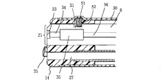
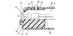
図1ないし図7は本発明の第1実施例に係わり、図1はカバー式内視鏡の構成を示す全体図、図2は図1の先端カバー部材の先端面の構成を示す構成図、図3は図2の送気送水ノズルの形状を示す断面図、図4はカバー用内視鏡を装着した第1の状態における図2のA−A線断面を示す断面図、図5はカバー用内視鏡を装着した第2の状態における図2のA−A線断面を示す断面図、図6は図4に示した第1の状態での送気送水ノズルの作用を説明する説明図、図7は図5に示した第2の状態での送気送水ノズルの作用を説明する説明図である。
【0013】
(構成)
図1に示す第1実施例のカバー式内視鏡2は、電子内視鏡で構成された内視鏡カバー用内視鏡(以下、カバー用内視鏡と略す)3と、このカバー用内視鏡3が装着されるチャンネル付き内視鏡カバー(以下、内視鏡カバーと略す)4とで構成される。
【0014】
カバー用内視鏡3は、可撓性の挿入部5と、この挿入部5の後端に設けた操作部6と、この操作部6から延出されたユニバーサルコード7とから構成される。カバー用内視鏡3の先端部には先端構成部8が設けられている。
【0015】
一方、カバー用内視鏡3を覆う汚染防止用の内視鏡カバー4は、挿入部カバー部11、操作部カバー12、ユニバーサルコードカバー13によって構成されていて、前記先端構成部8を被覆するよう挿入部カバー部11先端には先端カバー部材14が設けてある。これら内視鏡カバー4の各部は全て、内視鏡検査に使用される前に予め滅菌されているものが使用され、内視鏡検査に使用した後は廃棄される。
【0016】
上記挿入部カバー部11は、上記内視鏡カバー4のうち、カバー用内視鏡3の挿入部5を覆う部分及びその基端近傍を覆う部分で構成される。
【0017】
操作部カバー12は、カバー用内視鏡3の操作部6を覆うカバー部分である。また、ユニバーサルコードカバー13は、カバー用内視鏡3のユニバーサルコード7を覆う部分である。
【0018】
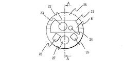
図2に示すように、先端カバー部材14の先端面には開口部21が設けてあり、先端構成部8と先端カバー部材14の位置決めとして先端カバー部材6の開口部21縁部には支持部22が設けられている。
【0019】
先端構成部5は観察窓23、照明窓24を有し、図示しない光源装置からの照明光がカバー用内視鏡3の挿入部5内に挿通された図示しないライトガイドを伝送し照明窓24より図示しない観察部位に照射され、その戻り光を観察窓23より入射するようになっている。
【0020】
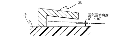
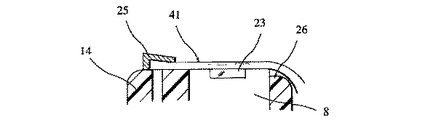
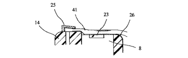
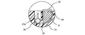
一方、先端カバー部材14先端には、送気送水方向が観察窓23が位置する方向となるよう設けた送気送水ノズル25があり、先端カバー部材14の送気送水の下流側となる外周面には切欠部26が設けてある。また、挿入部カバー部11には先端カバー部材14の先端で開口し処置具等を挿通させる処置具チャンネル27が設けられている。ここで、送気送水ノズル25は、その拡大断面である図3に示すように、先端カバー部材14の先端面に対して送気送水角度が0°〜10°となるように形成されている。
【0021】
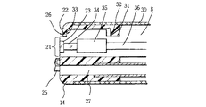
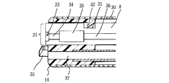
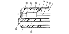
図2のA−A線断面である図4に示すように、先端構成部8には溝部31が設けてあり、その溝部31と係合するよう先端カバー部材14には係止爪32が設けられており、先端カバー部材14は外皮30により覆われ、係止爪32が径方向外側に押圧された場合、係止爪32を支持する係止爪32近傍の先端カバー部材14が弾性変形するようになっている。この場合、係止爪32と溝部31の係合面に部品のばらつき等により狭間が生じても狭間は0.5mm未満とする。
【0022】
また、先端構成部8と先端カバー部材14の位置決めとして先端構成部8には突き当て部33が設けられていて、先端カバー部材6の開口部21縁部に設けられた支持部22と突き当て部33が当接した場合には、先端構成部8の先端面と先端カバー部材14の先端面が同面となる構成となっている。
【0023】
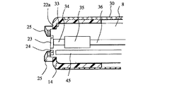
なお、観察窓23から入射した図示しない観察部位からの戻り光は、対物レンズ系34を介して撮像部35で撮像され、撮像信号は撮像ケーブル36により挿入部5内を伝送し外部の画像出力装置(図示せず)に出力され、信号処理された後、観察部位の画像が図示しないモニタに表示されるようになっている。
【0024】
(作用)
このように構成されたカバー式内視鏡2では、先端構成部8と先端カバー部材14に装着する際には、突き当て部33が係止爪32を径方向に押し上げ、係止爪32が径方向に押し上げられた状態で挿入され、係止爪32近傍の係止爪32を支持する先端カバー部材14の弾性力が働くことで、係止爪32が溝部31に係合し挿入完となる。
【0025】
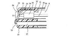
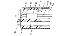
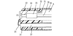
挿入が完了し、先端構成部8が先端カバー部材14に装着した状態では、係止爪32と溝部31の寸法のばらつき等により狭間が生じる可能性がある。この狭間によって、先端構成部8は先端カバー部材14に対し軸方向に移動するが、図4に示したように、軸方向先端側への移動量は先端構成部8に設けた突き当て部33と支持部22の当接によって規制され、先端構成部8の先端面は先端カバー部材14の先端面とほぼ同一面になる。また、軸方向基端側への移動は、図5に示すように、係止爪32と溝部31の係合により規制される。つまり、先端構成部8の移動量は、0.5mm以内に規制される。
【0026】
この先端カバー部材14の先端面に対し移動する先端構成部8の先端面において、先端カバー部材14に設けられた送気送水ノズル25は、図3に示したように送気送水角が0°〜10°であるため、図6及び図7に示すように水流(あるいは気流)41が先端構成部8先端面にほぼ平行に流出するため、図6のように先端構成部8の先端面と先端カバー部材14の先端面とがほぼ同一面となる場合でも、図7のように先端構成部8と先端カバー部材14とに段差が生じた場合でも、確実に観察窓部分に送気、送水をする作用がある。
【0027】
また、開口部21が観察窓23、照明窓24の縁部から離れて両者共通の開口部21としていることで観察窓23,照明窓24近辺に先端構成部8と先端カバー部材14の嵌合による狭間,段差が生じず、観察窓23,照明窓24付近には残水が起きにくくなっている。
【0028】
また、先端カバー部材14外周面に切欠部26を設けたことにより送気送水ノズル25から出た水、空気が先端構成部8先端面及び先端カバー部材14先端面上には残りにくくなっている。
【0029】
(効果)
従って、本実施例のカバー式内視鏡2では、先端構成部8の先端面の先端カバー部材14の先端面に対する位置の移動を内側方向に規制し、それに合う送気送水ノズル25を用いたため、たとえ、先端構成部8と先端カバー部材14の固定に若干のがたつきがあっても、洗滌能力は十分に確保できる。つまり、固定法に少々のがたつきがあっても、何ら洗滌能力には問題ないという効果がある。
【0030】
また、開口部21を観察窓23、照明窓24部分と共通とし、開口部21を大きく取ることで、観察窓23付近に残水が生じにくく、視野けられ等の光学的不具合が起きにくいという効果がある。
【0031】
さらに、先端カバー部材8端部に切欠部26を設けたことでさらに一層水切れが良くなるという効果がある。
【0032】
次に、第2実施例について説明する。図8ないし図14は本発明の第2実施例に係わり、図8は先端カバー部材の先端面の構成を示す構成図、図9はカバー用内視鏡を装着した図8のB−B線断面を示す断面図、図10は図8の送気送水ノズルの形状を示す断面図、図11はカバー用内視鏡を装着した第1の状態における図8のA−A線断面を示す断面図、図12はカバー用内視鏡を装着した第2の状態における図8のA−A線断面を示す断面図、図13は図11に示した第1の状態での送気送水ノズルの作用を説明する説明図、図14は図12に示した第2の状態での送気送水ノズルの作用を説明する説明図である。第2実施例は第1実施例とほとんど同じであるので、異なる構成のみ説明し、同一の構成には同じ符号を付け説明は省略する。
【0033】
(構成)
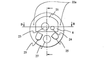
第2実施例では、先端カバー部材14の開口部21において、図8に示すように、送気送水の流路以外の部分に支持部22aを設け、図8のB−B線断面である図9に示すように、先端構成部8の前記支持部22aに対向する部分に突き当て部33が設けられている。
【0034】
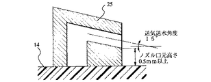
また、先端カバー部材14先端には、送気送水ノズル25を備えており、図10に示すように、前記送気送水ノズル25は、送気送水角度15°、ノズル口元高さ0.5mm以上に設定してある。
【0035】
なお、支持部22aと突き当て部33とが当接した場合には、図11に示すように、先端構成部8の先端面が先端カバー部材14の先端面から0.5mm突出するよう構成されており、図12のように係止爪32と溝部31で係合している面に狭間が生じて係合が十分でない場合で、先端構成部8が軸方向基端側へ多少移動するような場合でも、最悪先端カバー部材14の先端面と先端構成部8の先端面がほぼ同面となるよう構成されている。
【0036】
その他の構成は第1実施例と同じである。
【0037】
(作用)
本実施例では、突き当て部33、支持部22a及び係止爪32、溝部31は、第1実施例と同様の作用をし、先端構成部8の先端面の移動量は先端カバー部材14の先端面より外側へ0.5mm以内に規制される。
【0038】
次に、先端カバー部材14の先端面に対し移動する先端構成部8の先端面において、先端カバー部材14に設けられた送気送水ノズル25は送気送水角度15°で観察窓23に対し斜方から送気送水を行う。
【0039】
つまり、図13のような先端構成部8が先端カバー部材14から突出した場合には、一度先端構成部8の先端面に水(もしくは空気)を当てて、その後観察窓23上を水流(気流)41が通ることとなる。
【0040】
また、図14のような先端構成部8と先端カバー部材14が同一面となる場合には、送気送水ノズル25による水流(気流)41が直接観察窓23に当たる。
【0041】
なお、先端構成部8と先端カバー部材14との面が、図13と図14の中間となるような場合にも、図13のように作用をする。
【0042】
その他の作用は第1実施例と同じである。
【0043】
(効果)
従って、本実施例によれば、先端構成部8の先端面の先端カバー部材14の先端面に対する位置の移動を先端面より外側に規制し、その範囲で洗滌能力をもつ送気送水ノズル25を設けたことにより、第1実施例と同様に、たとえ先端構成部8と先端カバー部材14の固定に若干のがたつきがあっても洗滌能力は十分に確保できる。つまり、固定法に少々のがたつきがあっても何ら洗滌能力には問題ないという効果がある。
【0044】
また、先端構成部8の先端面を先端カバー部材14の先端面から突出させる方向で先端面の位置の変動幅を規制しているため、先端構成部8の先端面と先端カバー部材14の先端面との境界に落差が生じ、水が先端構成部8の先端面から外部に流れやすく、残水が起きにくいため、残水による視野の妨げが起きることを防ぐ効果がある。
【0045】
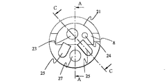
次に、第3実施例について説明する。図15ないし図20は本発明の第3実施例に係わり、図15は先端カバー部材の先端面の構成を示す構成図、図16はカバー用内視鏡を装着した図15のC−C線断面を示す断面図、図17はカバー用内視鏡を装着した第1の状態における図15のA−A線断面を示す断面図、図18はカバー用内視鏡を装着した第2の状態における図15のA−A線断面を示す断面図、図19は図18に示した第2の状態での送気送水ノズルの作用を説明する説明図、図20は図17に示した第1の状態での送気送水ノズルの作用を説明する説明図である。第3実施例は第1実施例とほとんど同じであるので、異なる構成のみ説明し、同一の構成には同じ符号を付け説明は省略する。
【0046】
(構成)
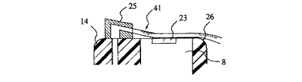
第3実施例では、図15のように先端カバー部材14において、観察上視野に入ってこない程度まで長くした送気送水ノズル25を開口部21に覆い被せる形で設置する。この場合、送気送水ノズル25が第1実施例における支持部22を兼ねる構成となる。
【0047】
また、先端構成部8の先端面が送気送水ノズル25に当接した場合は、図16に示すように、先端構成部8の先端面が先端カバー部材14の先端面と同面になるよう構成されており、また、図17に示すように、先端構成部8の軸方向基端側への移動は係止爪32と溝部31との当接により規制するよう構成している。その他の構成は第1実施例と同じである。
【0048】
(作用)
本実施例では、第1実施例と同様な作用により、先端構成部8を先端カバー部材14に挿入し終わると、先端構成部8と先端カバー部材14が係止爪32と溝部31の係合によって固定される。この際、係止爪32と溝部31が係合する面には、はめ合いの関係上、部品上の寸法のばらつきにより、狭間が生じる。この狭間により先端構成部8は先端カバー部材14に対し軸方向に移動するが、軸方向先端側への移動量は、図18に示すように、先端構成部8の先端面と送気送水ノズル25の当接によって規制され、先端構成部8の先端面は先端カバー部材14の先端面と同面になる。
【0049】
また、軸方向基端側への移動は係止爪32と溝部32の係合により規制される。つまり、先端構成部8の移動量は0.5mm以内に規制される(図17参照)。
【0050】
開口部21に覆い被せるよう設置した送気送水ノズル25は、図19に示すような先端構成部8の先端面が先端カバー部材14の先端面と同面になっている場合の他、図20に示すような先端構成部8と先端カバー部材14の嵌合による段差がある場合での、段差等の障害を回避して、水流41(気流)により観察窓23に直に送気送水を行える作用がある。
【0051】
その他の作用は第1実施例と同じである。
【0052】
(効果)
従って、本実施例によれば、先端構成部8の先端面の先端カバー部材14の先端面に対する位置の移動を先端面より内側にしその範囲で洗滌能力をもつ送気送水ノズル25を設けたため、先端構成部8と先端カバー部材14の固定に0.5mm程度のがたつきがあっても洗滌能力と水切れ性能は十分に確保できる。
【0053】
また、送気送水ノズル25を長くし、観察窓23に近づけたことによって、直に観察窓23に対し送気送水が行え、また、先端カバー部材14と先端構成部8との嵌合による段差、狭間等の障害を回避でき、洗滌性、水切れ性が向上するという効果がある。
【0054】
なお、本実施例において、送気送水ノズル25は全体を長く開口部21に覆い被せずともノズルの口元部分を伸ばしても同様の効果が得られる。
【0055】
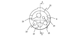
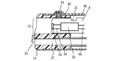
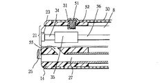
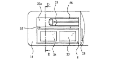
次に、第4実施例について説明する。図21ないし図27は本発明の第4実施例に係わり、図21は先端カバー部材の先端面の構成を示す構成図、図22はカバー用内視鏡を装着した図21のA−A線断面を示す断面図、図23はカバー用内視鏡の装着開始状態における図21のA−A線断面を示す断面図、図24はカバー用内視鏡の装着終了状態における図21のA−A線断面を示す断面図、図25はカバー用内視鏡を装着した先端カバー部材の第1の変形例の図21におけるA−A線断面を示す断面図、図26はカバー用内視鏡を装着した先端カバー部材の第2の変形例である側視型の先端カバー部材の構成を示す構成図、図27は図26のD−D線断面を示す断面図である。第4実施例は第1実施例とほとんど同じであるので、異なる構成のみ説明し、同一の構成には同じ符号を付け説明は省略する。
【0056】
(構成)
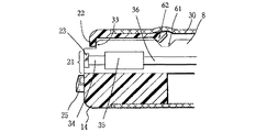
本実施例においては、図21に示すように、先端カバー部材14の先端面の構成は第1実施例と同様であり、図21のA−A線断面である図22に示すように、先端カバー部材14には、第1実施例で先端構成部8に設けた溝部31と係合する係止爪32の代わりに、固定ピン51とその固定ピン51に嵌合する穴部52を設けている。また、固定ピン51は外皮30が弾性変形した場合には、その弾性力が伝わるよう設けられている。ここで固定ピン51と穴部52の嵌合、及び固定ピン51と溝31とのはめ合いでの隙間は、部品バラツキを含めても0.5mm以内となるよう設けている。
【0057】
また、この時先端構成部8が軸方向先端側に移動した場合、移動量が最大の時、先端構成部8先端面が先端カバー部材14の先端面とほぼ同面となるよう構成されている。なお、図21において、2つの送気送水ノズル25のうち観察窓23から遠い方を送水専用とする。
【0058】
その他の構成は第1実施例と同じである。
【0059】
(作用)
本実施例では、先端構成部8が先端カバー部材14に挿入する際、図23に示すように、先端構成部8の先端にある斜面が固定ピン51を押し上げ挿入され、先端構成部8の挿入がさらに進み、外皮30の弾性力により固定ピン51が中心方向に押され、図24に示すように、溝部31に固定ピン51が嵌合すると先端構成部8と先端カバー部材14の固定は完了となる。
【0060】
先端構成部8と先端カバー部材14の固定が完了した場合、固定ピン51と溝部31とで嵌合している部分には隙間があり、先端構成部8は先端カバー部材14に対し軸方向に移動する。この時軸方向先端側に移動した場合には、先端構成部8の先端面は先端カバー部材14の先端面とほぼ同一面上になり(図22参照)、また、軸方向基端側に移動した場合には、先端構成部8の先端面が先端カバー部材14の先端面から最大でも0.5mm内側に入った状態に規制できる(図24参照)。
【0061】
この先端カバー部材14の先端面に対し移動する先端構成部8の先端面において、先端カバー部材14に設けられた送気送水ノズル25は、第1実施例と同じ作用をする。
【0062】
(効果)
従って、本実施例によれば、先端構成部8の先端面の先端カバー部材14の先端面に対する位置の移動量を送気送水ノズル25の洗滌能力範囲内に規制したため、先端構成部8と先端カバー部材14の固定に0.5mm程度のがたつきがあっても、第1実施例と同様に、洗滌能力、水切れ性能は十分に確保できる。
【0063】
また、開口部21縁部に支持部22を設けていないため、開口部21を大きく取ることができ、観察窓23,照明窓24近傍に残水が起きるような先端カバー部材14と先端構成部8との嵌合による狭間や段差は生じない。
【0064】
なお、送気送水ノズル25において、観察窓23から遠い方を送水用ノズルとすることで、ノズル口元に残水が起きた場合でもその残水が視野に入る可能性はより少なくなる。
【0065】
また、上記第1〜第4実施例において、図25のように先端カバー部材14に処置具チャンネル27と先端カバー部材14の先端構成部8が挿入される空間に導通孔55を設けてやることにより、先端カバー部材14を先端構成部8の狭間に入り込んだ水及び汚物を処置具チャンネル27を通じ回収し、除去することができる。
【0066】
さらに、側視型内視鏡においては、図26及び図26のD−D線断面である図27に示すように、処置具チャンネル27のチャンネル開口部27aと先端カバー部材14に先端構成部8が挿入される空間との間に導通口55を設けることにより、先端構成部8と先端カバー部材14との間に入った水もしくは汚物を導通口55からチャンネル開口部27aを通じ処置具チャンネル27に挿通される吸引チューブ56から回収できることより、より観察窓23上及び照明窓24上の水切れが良くなる。
【0067】
次に、本発明の参考例について説明する。
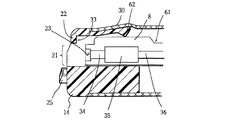
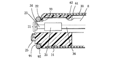
まず、第1参考例について説明する。図28ないし図30は本発明の第1参考例に係わり、図28は先端カバー部材の構成を示す断面図、図29は図28の先端カバー部材へのカバー用内視鏡の装着状態を示す断面図、図30は図28の溝部及び係止爪の作用を説明する拡大図である。第1参考例は第1実施例とほとんど同じであるので、異なる構成のみ説明し、同一の構成には同じ符号を付け説明は省略する。
【0068】
(構成)
本参考例では、先端構成部8には溝部61が設けてあり、その溝部61と係合するよう先端カバー部材14には係止爪62が設けられており、少なくとも係止爪62周辺は弾性部材から形成されている。
【0069】
また、先端カバー部材14の先端面には開口部21が設けてあり、先端構成部9と先端カバー部材14の位置決めとして、先端構成部8には突き当て部33が先端カバー部材14の開口部21縁部には支持部22が設けられている。
【0070】
なお、溝部61の先端側基板側の面は斜面を成しておりこの斜面に係合するよう係止爪62にも斜面が設けられている。
【0071】
また、突き当て部33と溝部61との距離より支持部22から係止爪62の距離を短く設定してある。
【0072】
その他の構成は第1実施例と同じである。
【0073】
(作用)
このように構成された本参考例においては、先端構成部8を先端カバー部材14に装着する際には、図29に示すように、突き当て部33が係止爪62を径方向に押し上げ挿入され溝部61に係止されることで装着完となる。
【0074】
装着が完了すると、支持部22から係止爪62までの距離は突き当て部33と溝部71までの距離より短いため、係止爪62周辺は弾性変形した状態で係止爪62と溝部61が係合する。
【0075】
この場合、弾性変形による弾性力により係止爪62が溝部61を、図30の矢印の方向に押圧する。すると、先端構成部8は軸方向先端側を径方向に押圧され、突き当て部33は支持部22と、また先端構成部8の径方向中心側の面と先端カバー部材14の径方向中心側の面は密着状態となる。
【0076】
その他の作用は第1実施例と同じである。
【0077】
(効果)
従って、本参考例では、先端構成部8と先端カバー部材14が送気送水ノズル25側で密着することにより、両者に狭間が無くなり送気送水時の障害となる部分が減り、第1実施例と同様に、安定した送気送水が行える効果がある。
【0078】
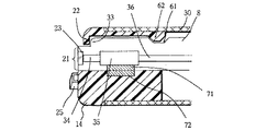
次に、第2参考例について説明する。図31は本発明の第2参考例に係る先端カバー部材の構成を示す断面図である。第2参考例は第1参考例とほとんど同じであるので、異なる構成のみ説明し、同一の構成には同じ符号を付け説明は省略する。
【0079】
(構成)
本第2参考例では、第1参考例と同様に、先端構成部8には溝部61を有し、その溝部61と係合するよう係止爪62が先端カバー部材14に設けられている。この場合、突き当て部33と支持部22の当接及び係止爪62と溝部61の係合により、先端構成部8と先端カバー部材14が位置決めするよう構成されている。
【0080】
また、先端構成部8の外周面には磁石71が設けてあり、先端カバー部材14にはその磁石71に対向する位置に磁石71と引力を発する向きに向けた磁石72が設けてある。
【0081】
その他の構成は第1参考例と同じである。
【0082】
(作用)
本第2参考例においては、先端構成部8が先端カバー部材14に挿入されると係止爪62と溝部61に係合する。その際軸方向先端側には突き当て部33と支持部22の当接により移動が規制され、先端構成部8と先端カバー部材14の位置決めされ、先端構成部8と先端カバー部材14の固定が完了する。また、磁石71、72の磁力による引力で先端構成部8と先端カバー部材14が密着する。
【0083】
その他の作用、効果は第1参考例と同じである。
【0084】
なお、磁石71、72による磁力でなくとも、粘着性のある物質を磁石の代わりに設けても同様の効果は得られる。
【0085】
次に、第3参考例について説明する。図32は本発明の第3参考例に係る先端カバー部材の構成を示す断面図である。第3参考例は第1参考例とほとんど同じであるので、異なる構成のみ説明し、同一の構成には同じ符号を付け説明は省略する。
【0086】
(構成)
本第3参考例では、第1参考例の係止爪62及び溝部61の代わりに、先端カバー部材14には、下穴貫通しためねじ部81が設けてあり、また先端カバー部材14の外周に設けられた外皮30の前記めねじ部81に対向する部分には貫通穴82が設けてあり、そのめねじ部81、貫通穴82に対し外部から固定ビス83を取り付けてある。この固定ビス83のねじ部長さは、外皮30の厚さ、先端カバー部材14の厚さ、先端カバー部材14と先端構成部8の狭間を合わせた長さよりも長いものとなっている。
【0087】
その他の構成は第1参考例と同じである。
【0088】
(作用)
本第1参考例においては、先端構成部8と先端カバー部材14に挿入し、突き当て部33が支持部22に当接し、先端構成部8の先端面と先端カバー部材14の先端面との位置決めをした後、外部から固定ビス83を締めることにより固定ビス83が先端構成部8を径方向中心側に押圧し、先端カバー部材14と密着状態にすることで両者を固定し、固定完了となる。
【0089】
その他の作用、効果は第1参考例と同じである。
【0090】
次に、第4参考例について説明する。図33は本発明の第4参考例に係る先端カバー部材の構成を示す断面図である。第4参考例は第1参考例とほとんど同じであるので、異なる構成のみ説明し、同一の構成には同じ符号を付け説明は省略する。
【0091】
(構成)
本第4参考例では、先端カバー部材8の先端面の外周全周部分に切欠部91を設け、その切欠部91には先端構成部8と先端カバー部材14を外挿するOリング92が備えてある。
【0092】
その他の構成は第1参考例と同じである。
【0093】
(作用)
本第4参考例においては、係止爪62と溝部61との係合と支持部22と突き当て部33の当接により、先端構成部8と先端カバー部材14の固定が完了する。その後Oリング92を切欠部91に外挿することで、Oリング92は先端構成部8と先端カバー部材14とをその弾性力で押圧し両者を密着させる。
【0094】
その他の作用、効果は第1参考例と同じである。
【0095】
なお、本発明は上記各実施例に限らず、各実施例間で発明の要旨を逸脱しない範囲で組み換え可能であることは言うまでもない。
【0096】
[付記]
(付記項1) 観察窓と照明窓とを先端の先端構成部に有するカバー用内視鏡と、
前記カバー用内視鏡の挿入部を外挿し、先端には前記観察窓と前記照明窓とに対向する部分に開口部を有し、先端面には送気送水ノズルを備えた先端カバー部材を有する内視鏡カバーと
からなるカバー式内視鏡において、
前記先端構成部の先端面位置と前記送気送水ノズルの口元高さ位置とが挿入方向に対して同位置か、あるいは前記送気送水ノズルの口元高さ位置の方が先端に位置する
ことを特徴とするカバー式内視鏡。
【0097】
(付記項2) 前記先端構成部の先端面と前記先端カバー部材の先端面との挿入方向位置を同一面、あるいは段差を構成する規制手段を備えた
ことを特徴とする付記項1に記載のカバー式内視鏡。
【0098】
(付記項3) 前記規制手段は、前記先端構成部と前記先端カバー部材との間に設けた挿入方向の当接面と、周方向の少なくとも1つの凹凸部である
ことを特徴とする付記項2に記載のカバー式内視鏡。
【0099】
(付記項4) 前記規制手段は、前記先端構成部と前記送気送水ノズルの一部である
ことを特徴とする付記項2に記載のカバー式内視鏡。
【0100】
(付記項5) 観察窓と照明窓とを先端の先端構成部に有するカバー用内視鏡と、
前記カバー用内視鏡の挿入部を外挿し、先端には前記観察窓と前記照明窓とに対向する部分に開口部を有し、先端面には送気送水ノズルを備えた先端カバー部材を有する内視鏡カバーと
からなるカバー式内視鏡において、
前記先端カバー部材の内部の少なくとも一部で、前記先端構成部が密着している
ことを特徴とするカバー式内視鏡。
【0101】
(付記項6) 観察窓と照明窓とを先端の先端構成部に有するカバー用内視鏡と、
前記カバー用内視鏡の挿入部を外挿し、先端には前記観察窓と前記照明窓とに対向する部分に開口部を有し、先端面には送気送水ノズルを備えた先端カバー部材を有する内視鏡カバーと
からなるカバー式内視鏡において、
前記先端カバー部材の内部の少なくとも一部で、前記先端構成部が前記送気送水ノズル側で密着している
ことを特徴とするカバー式内視鏡。
【0102】
(付記項7) 観察窓と照明窓を先端部の先端構成部に有するカバー用内視鏡と、
前記カバー用内視鏡の挿入部を外挿し、先端には前記観察窓と照明窓と対向する部分に開口部を設け、先端面には送気、送水ノズル備えた先端カバー部材を有する内視鏡カバーと
の組み合わせから構成されるカバー式内視鏡において、
前記先端カバー部材上の送気送水ノズルから先端構成部上の観察窓に至る部分において、先端カバー部材と先端構成部とに段差を設け、前記段差に合う送気送水ノズルを設けた
ことを特徴とするカバー式内視鏡。
【0103】
(付記項8) 前記先端カバー部材と前記先端構成部から成る前記段差は、前記先端構成部の方が内側になるよう規制した
ことを特徴とする付記項7に記載のカバー式内視鏡。
【0104】
(付記項9) 前記先端カバー部材と前記先端構成部から成る前記段差は、前記先端構成部の方が外側になるよう規制した
ことを特徴とする付記項7に記載のカバー式内視鏡。
【0105】
(付記項10) 前記送気送水ノズルの送気送水角度が0°〜10°である
ことを特徴とする付記項8に記載のカバー式内視鏡。
【0106】
(付記項11) 前記送気送水ノズルの送気送水角度が15°である
ことを特徴とする付記項9に記載のカバー式内視鏡。
【0107】
(付記項12) 前記先端構成部の先端面の位置を規制する規制手段を備え、
前記規制手段は、前記先端カバー部材の前記開口部に設けた支持部と前記先端構成部の外周に設けた突き当て部との当接から成る
ことを特徴とする付記項7に記載のカバー式内視鏡。
【0108】
(付記項13) 前記支持部が前記開口部全周にある
ことを特徴とする付記項12に記載のカバー式内視鏡。
【0109】
(付記項14) 前記支持部が前記開口部の一部分に設けた
ことを特徴とする付記項12に記載のカバー式内視鏡。
【0110】
(付記項15) 前記支持部を送気送水時に水もしくは気体が通る部分以外の部分に設けた
ことを特徴とする付記項14に記載のカバー式内視鏡。
【0111】
(付記項16) 前記送気送水ノズルを前記開口部上に覆い被せた状態で設けることにより、前記送気送水ノズルが前記先端構成部の位置を規制する前記支持部となる
ことを特徴とする付記項12に記載のカバー式内視鏡。
【0112】
(付記項17) 前記先端カバー部材と前記先端構成部とから成る前記段差において、前記先端構成部の方が常に前記開口部より内側となるようにした
ことを特徴とする付記項8に記載のカバー式内視鏡。
【0113】
(付記項18) 前記先端カバー部材と前記先端構成部とから成る前記段差において、前記先端構成部の方が常に前記開口部より外側となるようにした
ことを特徴とする付記項9に記載のカバー式内視鏡。
【0114】
(付記項19) 前記先端カバー部材と前記先端構成部から成る前記段差は、前記先端構成部の方が内側に0.5mm未満となるよう規制する
ことを特徴とする付記項8、12、17のいずれか1つに記載のカバー式内視鏡。
【0115】
(付記項20) 前記先端カバー部材と前記先端構成部から成る前記段差は、前記先端構成部の方が外側に0.5mm未満となるよう規制する
ことを特徴とする付記項8、12、17のいずれか1つに記載のカバー式内視鏡。
【0116】
(付記項21) 前記先端カバー部材の前記観察窓と前記照明窓と対向する部分は、共通の1つの前記開口部によって開口している
ことを特徴とする付記項7に記載のカバー式内視鏡。
【0117】
(付記項22) 前記送気送水ノズルが複数の場合、前記観察窓から遠い方を送水用とした
ことを特徴とする付記項7に記載のカバー式内視鏡。
【0118】
(付記項23) 前記先端カバー部材において、前記先端カバー部材の外周面に水切れが良いよう切欠部を設けた
ことを特徴とする付記項7に記載のカバー式内視鏡。
【0119】
(付記項24) 前記切欠部は、前記送気送水ノズルの下流側に設けた
ことを特徴とする付記項23に記載のカバー式内視鏡。
【0120】
(付記項25) 前記先端カバー部材において、前記先端カバー部材上で水切れが良いよう前記先端カバー部材を前記送気送水ノズルの下流側には設けない
ことを特徴とする付記項7に記載のカバー式内視鏡。
【0121】
(付記項26)
観察窓と照明窓を先端部の先端構成部に有するカバー用内視鏡と、
前記カバー用内視鏡の挿入部を外挿し、先端には前記観察窓と照明窓と対向する部分に開口部を設け先端面には送気、送水ノズルを備えた先端カバー部材を有する内視鏡カバーとの組み合わせから構成されるカバー式内視鏡において、
前記先端構成部と前記先端カバー部材とが先端面で送気送水の妨げにならないよう前記送気送水ノズル側に於いて密着している
ことを特徴としたカバー式内視鏡。
【0122】
(付記項27) 前記先端構成部と前記先端カバー部材とが前記先端カバー部材の弾性力により密着している
ことを特徴とする付記項26に記載のカバー式内視鏡。
【0123】
(付記項28) 前記先端構成部と前記先端カバー部材とが外部からの係止手段により密着している
ことを特徴とする付記項26に記載のカバー式内視鏡。
【0124】
(付記項29) 外部から前記先端構成部5を弾性部材で締め付けることにより、前記先端構成部と前記先端カバー部材が密着している
ことを特徴とする付記項28に記載のカバー式内視鏡。
【0125】
(付記項30) 外部から前記先端カバー部材と前記先端構成部をビス止めすることにより両者が密着している
ことを特徴とする付記項28に記載のカバー式内視鏡。
【0126】
(付記項31) 前記先端構成部と前記先端カバー部材が磁力により密着している
ことを特徴とする付記項27に記載のカバー式内視鏡。
【0127】
(付記項32) 前記先端構成部と前記先端カバー部材が粘着力により密着している
ことを特徴とする付記項27に記載のカバー式内視鏡。
【0128】
(付記項33) 前記弾性部材がOリングから成る
ことを特徴とする付記項29に記載のカバー式内視鏡。
【0129】
【発明の効果】
以上説明したように本発明のカバー式内視鏡によれば、先端構成部の先端面位置と送気送水ノズルの口元高さ位置とが挿入方向に対して同位置か、あるいは送気送水ノズルの口元高さ位置の方が先端に位置させているので、内視鏡カバーとカバー用内視鏡の固定時の固定方法によるがたつきや、製造時の部品の寸法のばらつきにより先端構成部の先端面の位置が変動しても、送気、送水等洗滌に不具合が生じることがないという効果がある。
【図面の簡単な説明】
【図1】本発明の第1実施例に係るカバー式内視鏡の構成を示す全体図
【図2】図1の先端カバー部材の先端面の構成を示す構成図
【図3】図2の送気送水ノズルの形状を示す断面図
【図4】カバー用内視鏡を装着した第1の状態における図2のA−A線断面を示す断面図
【図5】カバー用内視鏡を装着した第2の状態における図2のA−A線断面を示す断面図
【図6】図4に示した第1の状態での送気送水ノズルの作用を説明する説明図
【図7】図5に示した第2の状態での送気送水ノズルの作用を説明する説明図
【図8】本発明の第2実施例に係る先端カバー部材の先端面の構成を示す構成図
【図9】カバー用内視鏡を装着した図8のB−B線断面を示す断面図
【図10】図8の送気送水ノズルの形状を示す断面図
【図11】カバー用内視鏡を装着した第1の状態における図8のA−A線断面を示す断面図
【図12】カバー用内視鏡を装着した第2の状態における図8のA−A線断面を示す断面図
【図13】図11に示した第1の状態での送気送水ノズルの作用を説明する説明図
【図14】図12に示した第2の状態での送気送水ノズルの作用を説明する説明図
【図15】本発明の第3実施例に係る先端カバー部材の先端面の構成を示す構成図
【図16】カバー用内視鏡を装着した図15のC−C線断面を示す断面図
【図17】カバー用内視鏡を装着した第1の状態における図15のA−A線断面を示す断面図
【図18】カバー用内視鏡を装着した第2の状態における図15のA−A線断面を示す断面図
【図19】図18に示した第2の状態での送気送水ノズルの作用を説明する説明図
【図20】図17に示した第1の状態での送気送水ノズルの作用を説明する説明図
【図21】本発明の第4実施例に係る先端カバー部材の先端面の構成を示す構成図
【図22】カバー用内視鏡を装着した図21のA−A線断面を示す断面図
【図23】カバー用内視鏡の装着開始状態における図21のA−A線断面を示す断面図
【図24】カバー用内視鏡の装着終了状態における図21のA−A線断面を示す断面図
【図25】カバー用内視鏡を装着した先端カバー部材の第1の変形例の図21におけるA−A線断面を示す断面図
【図26】カバー用内視鏡を装着した先端カバー部材の第2の変形例である側視型の先端カバー部材の構成を示す構成図
【図27】図26のD−D線断面を示す断面図
【図28】本発明の第1参考例に係る先端カバー部材の構成を示す断面図
【図29】図28の先端カバー部材へのカバー用内視鏡の装着状態を示す断面図
【図30】図28の溝部及び係止爪の作用を説明する拡大図
【図31】本発明の第2参考例に係る先端カバー部材の構成を示す断面図
【図32】本発明の第3参考例に係る先端カバー部材の構成を示す断面図
【図33】本発明の第4参考例に係る先端カバー部材の構成を示す断面図
【符号の説明】
2…カバー式内視鏡
3…カバー用内視鏡
4…内視鏡カバー
5…挿入部
6…操作部
7…ユニバーサルコード
8…先端構成部
11…挿入部カバー部
12…操作部カバー
13…ユニバーサルコードカバー
14…先端カバー部材
21…開口部
22,22a…支持部
23…観察窓
24…照明窓
25…送気送水ノズル
26,91…切欠部
27…処置具チャンネル
27a…処置具チャンネル開口部
30…外皮
31,61…溝部
32,62…係止爪
33…突き当て部
34…対物レンズ系
35…撮像部
36…撮像ケーブル
41…水流
51…固定ピン
52…穴部
55…導通口
56…吸引チューブ
71,72…磁石
81…めねじ部
82…貫通穴
83…固定ビス
92…Oリング[0001]
[Industrial applications]
The present invention provides a cover endoscope having an observation window and an illumination window at the distal end portion of the distal end, and a distal end cover member provided with an air supply / water supply nozzle on the distal end surface by externally inserting the insertion portion of the cover endoscope. A cover-type endoscope comprising an endoscope cover having the cover.
[0002]
[Prior art]
2. Description of the Related Art Conventionally, an endoscope used for observation inside a human body or the like is known in which an insertion portion is covered with a protective tube in order to prevent body fluid or the like from adhering to the insertion portion into a body cavity. . After use of the endoscope, the protective tube is removed and replaced with a new protective tube. Therefore, it is possible to prevent the insertion portion from being contaminated, and it is not necessary to wash them, so that the trouble of washing can be saved.
[0003]
Specifically, for example, as shown in FIG. 2 of US Pat. No. 4,809,678, there is a device in which the entire insertion portion is covered with a cover provided with a transparent portion on the front surface of the observation optical system. The fixing of the insertion portion cover and the endoscope insertion portion is performed by the frictional force of the elastic end provided on the cover hand side.
[0004]
As shown in FIG. 3 of US Pat. No. 4,809,678, a replaceable distal end cover is provided at the distal end of the endoscope, and the periphery of the proximal end side of the distal end cover is fixed by the frictional force of the elastic end of the insertion portion cover having an open distal end. There is also. The details of the method of fixing the distal end cover and the endoscope distal end are not described.
[0005]
Separately, as in the case of Japanese Utility Model Application Laid-Open No. 58-74212 and Japanese Utility Model Application Laid-open No. 58-77318, a type in which the insertion portion cover having an open front surface of the observation optical system is fixed watertight from the outer surface by a separate locking member is proposed. Have been.
[0006]
In Japanese Patent Application No. 5-111873, a seal member is provided between the distal end cover member of the endoscope cover and the distal end component of the cover endoscope, and both are fixed. Further, in Japanese Patent Application No. 5-176971 and US Pat. No. 5,193,525, the observation window and the illumination window are made to protrude and fitted into the opening corresponding to the above-mentioned portion provided at the end of the endoscope cover. What is fixed is disclosed.
[0007]
[Problems to be solved by the invention]
However, in Japanese Utility Model Application Laid-Open No. 58-74212, the cover endoscope and the endoscope cover are fixed in a watertight state from the outside by a separate locking body. Although the member and the distal end of the cover endoscope are fixed in a water-tight state by a member, there is a possibility that the fixed state of the two cannot be reliably maintained with these conventional techniques, that is, a certain amount of both may be axially displaced. Stable air supply is possible when the tip surface of the tip component moves from inside to outside from the tip surface of the tip cover member, as well as optical defects such as the possibility of movement and visibility. The effect of water supply is not obtained, and depending on the amount of movement, water supply and air supply are not performed as expected, and there is a possibility that cleaning and running out of water may occur.
[0008]
In Japanese Patent Application No. 5-176971 and the CPUs 5,193,525, since the observation window and the illumination window are fitted with the opening at the tip of the tip cover member, a step or a gap is formed around the observation window and the illumination window. Residual water after water supply is likely to occur at the site, and there is a possibility that an optical defect such as water droplets being seen in the field of view or covering the entire observation window with water.
[0009]
The present invention has been made in view of the above circumstances, and with a simple configuration, the endoscope cover and the endoscope for the cover have a looseness due to a fixing method at the time of fixing, and a variation in dimensions of parts during manufacturing. Accordingly, it is an object of the present invention to provide a cover-type endoscope which does not cause a problem in cleaning such as air supply and water supply even when the position of the distal end surface of the distal end portion changes.
[0010]
[Means for Solving the Problems]
A first cover-type endoscope of the present invention includes a cover endoscope having an observation window and an illumination window at a distal end component, and an insertion portion of the cover endoscope. A cover-type endoscope having an opening in a portion opposed to the observation window and the illumination window, and an endoscope cover having a tip cover member provided with an air / water nozzle on a tip surface, The distal end portion of the endoscope cover and the distal end cover portion of the endoscope cover,
The front face of the tip component and the rear face of the tip cover member can abut, and the locking claw or fixing pin provided on the tip cover member and the rear face of the groove provided in the tip component can abut. Or a locking claw or a fixing pin provided on the distal end cover member and a rearward surface and a forward surface of the groove provided on the distal end component can be brought into contact with each other.A locking means for locking the tip cover to the tip component,But,The distal end surface of the cover endoscope is substantially the same as the distal end surface of the endoscope cover provided with an air / water supply nozzle.SameFrom the position where the end surface for the cover is movable within a range of 0.5 mm or less between the end surface of the endoscope cover and a position behind the end surface having the air / water supply nozzle in the endoscope cover. The air supply / water supply nozzle is formed such that the air supply / water supply angle is 0 ° to 10 ° with respect to a distal end surface of the endoscope cover provided with the air supply / water supply nozzle. It is characterized by having done.
Further, the second cover-type endoscope of the present invention includes an endoscope for a cover having an observation window and an illumination window at a distal end component, and an insertion portion of the endoscope for a cover, A cover type endoscope having an opening at a portion facing the observation window and the illumination window, and an endoscope cover having a tip cover member provided with an air / water supply nozzle at a tip end surface. The distal end portion of the endoscope cover and the distal end cover portion of the endoscope coverThe locking claws or fixing pins provided on the distal end cover member and the rearward facing surface and the forward facing surface provided on the distal end component can be brought into contact with each other.A locking means for locking the tip cover to the tip component,But,The distal end surface of the cover endoscope is substantially the same as the distal end surface of the endoscope cover provided with an air / water supply nozzle.SameFrom the position, the distal end surface of the cover endoscope is movably regulated between a position forward of the distal end surface provided with the air / water supply nozzle in the endoscope cover, and locked. Preferably, the air / water supply nozzle has a mouth height equal to or greater than the movable distance.
[0011]
【Example】
Hereinafter, embodiments of the present invention will be described with reference to the drawings.
[0012]
1 to 7 relate to a first embodiment of the present invention, FIG. 1 is an overall view showing a configuration of a cover type endoscope, FIG. 2 is a configuration diagram showing a configuration of a distal end surface of a distal end cover member of FIG. 1, 3 is a cross-sectional view showing the shape of the air / water supply nozzle of FIG. 2, FIG. 4 is a cross-sectional view showing a cross section taken along line AA of FIG. 2 in a first state in which a cover endoscope is mounted, and FIG. FIG. 6 is a cross-sectional view showing a cross section taken along line AA of FIG. 2 in a second state in which the endoscope is mounted, and FIG. 6 is an explanatory view illustrating the operation of the air / water supply nozzle in the first state shown in FIG. FIG. 7 is an explanatory view for explaining the operation of the air / water supply nozzle in the second state shown in FIG.
[0013]
(Constitution)
A cover-
[0014]
The cover endoscope 3 includes a flexible insertion portion 5, an
[0015]
On the other hand, an
[0016]
The insertion
[0017]
The
[0018]
As shown in FIG. 2, an
[0019]
The distal end component 5 has an
[0020]
On the other hand, at the tip of the distal
[0021]
As shown in FIG. 4 which is a cross section taken along the line AA in FIG. 2, a
[0022]
In order to position the
[0023]
The return light from the observation site (not shown) incident from the
[0024]
(Action)
In the cover-
[0025]
When the insertion is completed and the
[0026]
At the distal end surface of the
[0027]
In addition, the
[0028]
In addition, the provision of the
[0029]
(effect)
Therefore, in the cover-
[0030]
Further, by making the
[0031]
Further, the provision of the
[0032]
Next, a second embodiment will be described. 8 to 14 relate to a second embodiment of the present invention. FIG. 8 is a configuration diagram showing a configuration of a distal end surface of a distal end cover member. FIG. 9 is a BB line of FIG. FIG. 10 is a cross-sectional view showing a cross section, FIG. 10 is a cross-sectional view showing the shape of the air / water supply nozzle of FIG. 8, and FIG. 11 is a cross-sectional view showing a cross section taken along line AA of FIG. FIG. 12 is a cross-sectional view showing a cross section taken along the line AA of FIG. 8 in a second state in which the endoscope for a cover is mounted. FIG. 13 is a view of the air / water supply nozzle in the first state shown in FIG. FIG. 14 is an explanatory diagram for explaining the operation, and FIG. 14 is an explanatory diagram for explaining the operation of the air / water supply nozzle in the second state shown in FIG. Since the second embodiment is almost the same as the first embodiment, only different configurations will be described, and the same configurations will be denoted by the same reference numerals and description thereof will be omitted.
[0033]
(Constitution)
In the second embodiment, as shown in FIG. 8, a
[0034]
Further, an air supply /
[0035]
When the
[0036]
Other configurations are the same as those of the first embodiment.
[0037]
(Action)
In the present embodiment, the butting
[0038]
Next, on the distal end surface of the
[0039]
That is, when the
[0040]
When the
[0041]
It should be noted that, even when the surface of the
[0042]
Other operations are the same as those of the first embodiment.
[0043]
(effect)
Therefore, according to the present embodiment, the movement of the position of the distal end surface of the
[0044]
Further, since the variation width of the position of the distal end surface is regulated in a direction in which the distal end surface of the
[0045]
Next, a third embodiment will be described. 15 to 20 relate to the third embodiment of the present invention. FIG. 15 is a configuration diagram showing the configuration of the distal end surface of the distal end cover member. FIG. 16 is a line CC of FIG. FIG. 17 is a cross-sectional view showing a cross section, FIG. 17 is a cross-sectional view showing a cross section taken along line AA of FIG. 15 in a first state in which the cover endoscope is mounted, and FIG. 18 is a second state in which the cover endoscope is mounted. FIG. 19 is a cross-sectional view showing a cross section taken along line AA of FIG. 15, FIG. 19 is an explanatory view illustrating the operation of the air / water supply nozzle in the second state shown in FIG. 18, and FIG. It is explanatory drawing explaining the effect | action of the air supply / water supply nozzle in the state of FIG. Since the third embodiment is almost the same as the first embodiment, only different configurations will be described.
[0046]
(Constitution)
In the third embodiment, as shown in FIG. 15, the air /
[0047]
When the distal end surface of the
[0048]
(Action)
In the present embodiment, when the
[0049]
The movement toward the base end in the axial direction is restricted by the engagement between the locking
[0050]
The air /
[0051]
Other operations are the same as those of the first embodiment.
[0052]
(effect)
Therefore, according to the present embodiment, since the movement of the position of the distal end surface of the
[0053]
Further, by making the air /
[0054]
In this embodiment, the same effect can be obtained even if the mouth portion of the air /
[0055]
Next, a fourth embodiment will be described. 21 to 27 relate to a fourth embodiment of the present invention, FIG. 21 is a configuration diagram showing a configuration of a distal end surface of a distal end cover member, and FIG. 22 is a line AA of FIG. 21 equipped with a cover endoscope. 23 is a cross-sectional view showing a cross section, FIG. 23 is a cross-sectional view showing a cross section taken along the line AA of FIG. 21 in a state where mounting of the cover endoscope is started, and FIG. FIG. 25 is a cross-sectional view showing a cross section taken along line AA, FIG. 25 is a cross-sectional view showing a cross section taken along line AA in FIG. 21 of a first modification of the distal end cover member equipped with the endoscope for a cover, and FIG. FIG. 27 is a configuration diagram showing a configuration of a side view type front end cover member which is a second modified example of the front end cover member equipped with. Since the fourth embodiment is almost the same as the first embodiment, only different configurations will be described, and the same configurations will be denoted by the same reference numerals and description thereof will be omitted.
[0056]
(Constitution)
In the present embodiment, as shown in FIG. 21, the configuration of the distal end surface of the distal
[0057]
Further, at this time, when the
[0058]
Other configurations are the same as those of the first embodiment.
[0059]
(Action)
In this embodiment, when the
[0060]
When the fixing of the
[0061]
On the distal end surface of the
[0062]
(effect)
Therefore, according to the present embodiment, the amount of movement of the position of the distal end surface of the
[0063]
In addition, since the supporting
[0064]
In the air /
[0065]
In the first to fourth embodiments, the
[0066]
Further, in the side-view type endoscope, as shown in FIG. 26 and FIG. 27 which is a cross-sectional view taken along the line DD of FIG. Is provided between the distal
[0067]
Next, a reference example of the present invention will be described.
First,First reference exampleWill be described. FIG. 28 to FIG.First reference example28 is a cross-sectional view showing the configuration of the distal end cover member, FIG. 29 is a cross-sectional view showing the mounting state of the cover endoscope on the distal end cover member of FIG. 28, and FIG. It is an enlarged view explaining the effect | action of a nail.First reference exampleAre almost the same as those in the first embodiment, only different configurations will be described, and the same configurations will be denoted by the same reference numerals and description thereof will be omitted.
[0068]
(Constitution)
BookReference exampleIn the embodiment, a
[0069]
An
[0070]
The surface of the
[0071]
Further, the distance between the
[0072]
Other configurations are the same as those of the first embodiment.
[0073]
(Action)
Book composed in this wayReference exampleIn mounting the
[0074]
When the mounting is completed, the distance between the
[0075]
In this case, the locking
[0076]
Other operations are the same as those of the first embodiment.
[0077]
(effect)
Therefore, the bookReference exampleIn this case, the
[0078]
next,Second reference exampleWill be described. FIG.Second reference exampleIt is sectional drawing which shows the structure of the front-end | tip cover member concerning this.Second reference exampleIsFirst reference exampleTherefore, only different configurations will be described, and the same configurations will be denoted by the same reference numerals and description thereof will be omitted.
[0079]
(Constitution)
BookSecond reference exampleThenFirst reference exampleSimilarly to the above, the
[0080]
Further, a
[0081]
Other configurations areFirst reference exampleIs the same as
[0082]
(Action)
BookSecond reference exampleIn, when the
[0083]
Other actions and effectsFirst reference exampleIs the same as
[0084]
It should be noted that the same effect can be obtained by providing a sticky substance instead of the magnets, instead of the magnetic force by the
[0085]
next,Third reference exampleWill be described. FIG.Third reference exampleIt is sectional drawing which shows the structure of the front-end | tip cover member concerning this.Third reference exampleIsFirst reference exampleTherefore, only different configurations will be described, and the same configurations will be denoted by the same reference numerals and description thereof will be omitted.
[0086]
(Constitution)
BookThird reference exampleThenFirst reference exampleInstead of the locking
[0087]
Other configurations areFirst reference exampleIs the same as
[0088]
(Action)
BookFirst reference exampleIn the above, after being inserted into the
[0089]
Other actions and effectsFirst reference exampleIs the same as
[0090]
next,Fourth reference exampleWill be described. FIG.Fourth reference exampleIt is sectional drawing which shows the structure of the front-end | tip cover member concerning this.Fourth reference exampleIsFirst reference exampleTherefore, only different configurations will be described, and the same configurations will be denoted by the same reference numerals and description thereof will be omitted.
[0091]
(Constitution)
BookFourth reference exampleIn this embodiment, a
[0092]
Other configurations areFirst reference exampleIs the same as
[0093]
(Action)
BookFourth reference exampleIn this case, the fixing of the
[0094]
Other actions and effectsFirst reference exampleIs the same as
[0095]
It is needless to say that the present invention is not limited to the above embodiments, and can be recombined between the embodiments without departing from the spirit of the invention.
[0096]
[Appendix]
(Additional Item 1) An endoscope for a cover having an observation window and an illumination window at the distal end component,
Extrapolate the insertion part of the endoscope for the cover, at the tip has an opening at a portion facing the observation window and the illumination window, a tip cover member provided with an air / water nozzle on the tip surface. With an endoscope cover
In a cover type endoscope consisting of
The tip surface position of the tip component and the mouth height position of the air / water nozzle are the same with respect to the insertion direction, or the mouth height position of the air / water nozzle is located at the tip.
A cover-type endoscope, characterized in that:
[0097]
(Additional Item 2) A restricting means is provided which defines the insertion direction position of the distal end surface of the distal end component and the distal end surface of the distal end cover member on the same plane or a step.
2. The cover-type endoscope according to claim 1, wherein
[0098]
(Additional Item 3) The regulating means is a contact surface in the insertion direction provided between the distal end component and the distal end cover member, and at least one uneven portion in the circumferential direction.
3. The cover-type endoscope according to
[0099]
(Additional Item 4) The restricting means is a part of the distal end component and the air / water supply nozzle.
3. The cover-type endoscope according to
[0100]
(Additional Item 5) An endoscope for a cover having an observation window and an illumination window at the distal end component,
Extrapolate the insertion part of the endoscope for the cover, at the tip has an opening at a portion facing the observation window and the illumination window, a tip cover member provided with an air / water nozzle on the tip surface. With an endoscope cover
In a cover type endoscope consisting of
At least a part of the inside of the tip cover member, the tip component is in close contact
A cover-type endoscope, characterized in that:
[0101]
(Additional Item 6) An endoscope for a cover having an observation window and an illumination window at the distal end component,
Extrapolate the insertion part of the endoscope for the cover, at the tip has an opening at a portion facing the observation window and the illumination window, a tip cover member provided with an air / water nozzle on the tip surface. With an endoscope cover
In a cover type endoscope consisting of
At least a part of the inside of the tip cover member, the tip component is in close contact with the air / water supply nozzle side.
A cover-type endoscope, characterized in that:
[0102]
(Additional Item 7) An endoscope for a cover having an observation window and an illumination window at the distal end component of the distal end portion,
An insertion section of the cover endoscope is extrapolated, an opening is provided at a portion at a tip opposite to the observation window and the illumination window, and an endoscope having a tip cover member provided with air supply and water supply nozzles at a tip surface. With mirror cover
In a cover type endoscope composed of a combination of
In the portion from the air / water nozzle on the tip cover member to the observation window on the tip component, a step was provided between the tip cover member and the tip component, and an air / water nozzle matching the step was provided.
A cover-type endoscope, characterized in that:
[0103]
(Additional Item 8) The step formed by the front end cover member and the front end component is regulated such that the front end component is inside.
8. The cover-type endoscope according to claim 7, wherein:
[0104]
(Additional Item 9) The step formed by the tip cover member and the tip component is regulated such that the tip component is located outside.
8. The cover-type endoscope according to claim 7, wherein:
[0105]
(Supplementary Item 10) The air / water angle of the air / water nozzle is 0 ° to 10 °.
9. The cover-type endoscope according to
[0106]
(Supplementary Item 11) The air / water supply angle of the air / water supply nozzle is 15 °.
10. The cover-type endoscope according to additional item 9, wherein:
[0107]
(Supplementary Item 12) A regulating unit that regulates a position of a tip end surface of the tip end component,
The restricting means comprises an abutment between a support provided at the opening of the tip cover member and an abutment provided on the outer periphery of the tip component.
8. The cover-type endoscope according to claim 7, wherein:
[0108]
(Additional Item 13) The support portion is located all around the opening.
13. The cover-type endoscope according to
[0109]
(Additional Item 14) The support portion is provided in a part of the opening.
13. The cover-type endoscope according to
[0110]
(Additional Item 15) The support portion is provided in a portion other than a portion through which water or gas passes during air / water supply.
15. The cover-type endoscope according to
[0111]
(Supplementary Note 16) By providing the air / water nozzle over the opening, the air / water nozzle serves as the support portion that regulates the position of the distal end component.
13. The cover-type endoscope according to
[0112]
(Supplementary Note 17) In the step formed by the tip cover member and the tip component, the tip component is always located inside the opening.
9. The cover-type endoscope according to
[0113]
(Additional Item 18) In the step formed by the tip cover member and the tip component, the tip component is always located outside the opening.
10. The cover-type endoscope according to additional item 9, wherein:
[0114]
(Additional Item 19) The step formed by the distal end cover member and the distal end component regulates the distal end component to be less than 0.5 mm inward.
The cover-type endoscope according to any one of
[0115]
(Supplementary Item 20) The step formed by the distal end cover member and the distal end constituent portion regulates the distal end constituent portion to be less than 0.5 mm outward.
The cover-type endoscope according to any one of
[0116]
(Additional Item 21) A portion of the distal end cover member facing the observation window and the illumination window is opened by one common opening.
8. The cover-type endoscope according to claim 7, wherein:
[0117]
(Additional item 22) When there are a plurality of the air / water supply nozzles, the one far from the observation window is used for water supply.
8. The cover-type endoscope according to claim 7, wherein:
[0118]
(Additional Item 23) In the distal end cover member, a cutout portion is provided on the outer peripheral surface of the distal end cover member so that the drainage is good.
8. The cover-type endoscope according to claim 7, wherein:
[0119]
(Additional Item 24) The notch is provided on the downstream side of the air / water supply nozzle.
24. The cover-type endoscope according to
[0120]
(Additional Item 25) In the distal end cover member, the distal end cover member is not provided on the downstream side of the air / water supply nozzle so that drainage on the distal end cover member is good.
8. The cover-type endoscope according to claim 7, wherein:
[0121]
(Appendix 26)
An endoscope for a cover having an observation window and an illumination window at the distal end portion of the distal end portion,
An insertion section of the cover endoscope is extrapolated, and an opening is provided at a distal end portion at a portion facing the observation window and the illumination window, and a distal end surface has a distal end cover member provided with an air supply and a water supply nozzle. In a cover type endoscope composed of a combination with a mirror cover,
The distal end component and the distal end cover member are in close contact with each other on the air / water supply nozzle side so as not to hinder the air / water supply at the distal end surface.
A cover-type endoscope characterized in that:
[0122]
(Additional Item 27) The distal end component and the distal end cover member are in close contact with each other by the elastic force of the distal end cover member.
27. The cover-type endoscope according to
[0123]
(Additional Item 28) The distal end component and the distal end cover member are in close contact with each other by an external locking means.
27. The cover-type endoscope according to
[0124]
(Supplementary Item 29) The distal end component and the distal end cover member are in close contact with each other by fastening the distal end component 5 from outside with an elastic member.
29. The cover-type endoscope according to attachment 28, wherein:
[0125]
(Additional item 30) The tip cover member and the tip component are screwed from the outside so that they are in close contact with each other.
29. The cover-type endoscope according to attachment 28, wherein:
[0126]
(Additional Item 31) The distal end component and the distal end cover member are closely adhered by magnetic force.
28. The cover-type endoscope according to
[0127]
(Additional Item 32) The distal end component and the distal end cover member are in close contact with each other by adhesive force.
28. The cover-type endoscope according to
[0128]
(Additional Item 33) The Elastic Member is an O-ring
[0129]
【The invention's effect】
As described above, according to the cover-type endoscope of the present invention, the distal end surface position of the distal end component and the mouth height position of the air / water supply nozzle are the same in the insertion direction, or the air / water supply nozzle The mouth height position is located at the front end, so the end component may be loose due to the looseness of the endoscope cover and the endoscope for the cover when the cover endoscope is fixed, and the dimensional variation of the parts during manufacturing. Even if the position of the front end surface is changed, there is an effect that no trouble occurs in cleaning such as air supply and water supply.
[Brief description of the drawings]
FIG. 1 is an overall view showing a configuration of a cover type endoscope according to a first embodiment of the present invention.
FIG. 2 is a configuration diagram showing a configuration of a distal end surface of the distal end cover member of FIG. 1;
FIG. 3 is a sectional view showing the shape of the air / water supply nozzle of FIG. 2;
FIG. 4 is a cross-sectional view showing a cross section taken along line AA of FIG. 2 in a first state in which a cover endoscope is mounted.
FIG. 5 is a cross-sectional view showing a cross section taken along line AA of FIG. 2 in a second state in which the endoscope for a cover is mounted.
FIG. 6 is an explanatory diagram for explaining the operation of the air / water supply nozzle in the first state shown in FIG. 4;
FIG. 7 is an explanatory diagram for explaining the operation of the air / water supply nozzle in the second state shown in FIG. 5;
FIG. 8 is a configuration diagram showing a configuration of a distal end surface of a distal end cover member according to a second embodiment of the present invention.
9 is a cross-sectional view showing a cross section taken along line BB of FIG. 8 with the endoscope for a cover attached.
FIG. 10 is a sectional view showing the shape of the air / water supply nozzle of FIG. 8;
11 is a cross-sectional view showing a cross section taken along line AA of FIG. 8 in a first state in which the cover endoscope is mounted.
FIG. 12 is a cross-sectional view showing a cross section taken along line AA of FIG. 8 in a second state in which the cover endoscope is mounted.
FIG. 13 is an explanatory diagram for explaining the operation of the air / water supply nozzle in the first state shown in FIG. 11;
FIG. 14 is an explanatory view illustrating the operation of the air / water supply nozzle in the second state shown in FIG. 12;
FIG. 15 is a configuration diagram showing a configuration of a distal end surface of a distal end cover member according to a third embodiment of the present invention.
16 is a cross-sectional view showing a cross section taken along line CC of FIG. 15 with the cover endoscope attached.
17 is a cross-sectional view showing a cross section taken along line AA of FIG. 15 in a first state in which the endoscope for a cover is mounted.
18 is a cross-sectional view showing a cross section taken along line AA of FIG. 15 in a second state in which the cover endoscope is mounted.
FIG. 19 is an explanatory diagram illustrating the operation of the air / water supply nozzle in the second state shown in FIG. 18;
FIG. 20 is an explanatory diagram illustrating the operation of the air / water supply nozzle in the first state shown in FIG. 17;
FIG. 21 is a configuration diagram showing a configuration of a distal end surface of a distal end cover member according to a fourth embodiment of the present invention.
22 is a cross-sectional view showing a cross section taken along line AA of FIG. 21 with the cover endoscope mounted.
23 is a cross-sectional view showing a cross section taken along line AA of FIG. 21 in a state where mounting of the endoscope for a cover is started.
24 is a cross-sectional view showing a cross section taken along line AA of FIG. 21 in a state where the mounting of the cover endoscope is completed.
FIG. 25 is a cross-sectional view showing a cross section taken along line AA in FIG. 21 of a first modified example of the distal end cover member equipped with the cover endoscope;
FIG. 26 is a configuration diagram showing a configuration of a side-view type distal end cover member which is a second modified example of the distal end cover member to which the cover endoscope is attached.
FIG. 27 is a sectional view showing a section taken along line DD of FIG. 26;
FIG. 28 of the present invention.First reference exampleSectional view showing the configuration of the tip cover member according to FIG.
29 is a cross-sectional view showing a state where the cover endoscope is attached to the distal end cover member of FIG. 28;
FIG. 30 is an enlarged view illustrating the operation of the groove and the locking claw in FIG. 28;
FIG. 31 of the present invention.Second reference exampleSectional view showing the configuration of the tip cover member according to FIG.
FIG. 32 of the present invention.Third reference exampleSectional view showing the configuration of the tip cover member according to FIG.
FIG. 33 of the present invention.Fourth reference exampleSectional view showing the configuration of the tip cover member according to FIG.
[Explanation of symbols]
2. Cover type endoscope
3. Endoscope for cover
4: Endoscope cover
5. Insertion part
6 Operation unit
7… Universal cord
8 Tip configuration
11 ... insert part cover part
12 ... Operation unit cover
13. Universal code cover
14. Tip cover member
21 ... Opening
22, 22a ... support part
23 Observation window
24 ... Lighting window
25 ... Air / water nozzle
26, 91 ... Notch
27… Treatment tool channel
27a: treatment instrument channel opening
30 ... skin
31, 61 ... groove
32, 62 ... locking claw
33 ... Butting part
34 Objective lens system
35 ... Imaging unit
36 ... Imaging cable
41 ... water current
51 ... fixed pin
52 ... hole
55 ... conduction port
56 ... Suction tube
71, 72 ... magnet
81… Female thread
82 ... Through-hole
83 ... fixed screw
92… O-ring
Claims (2)
前記カバー用内視鏡の先端構成部と前記内視鏡カバーの先端カバー部には、
先端構成部の前向面と先端カバー部材の後向面とが当接し得るとともに先端カバー部材に設けた係止爪又は固定ピンと先端構成部に設けた溝部の後向面とが当接し得えてなる、
あるいは先端カバー部材に設けた係止爪又は固定ピンと先端構成部に設けた溝部の後向面及び前向面とが当接し得えてなる、
前記先端構成部に前記先端カバー部を係止する係止手段を有し、
前記係止手段が、
前記カバー用内視鏡の先端面が前記内視鏡カバーにおける送気送水ノズルを備えた先端面と略面一となる位置から、
前記カバー用内視鏡の先端面が前記内視鏡カバーにおける送気送水ノズルを備えた先端面より後方となる位置との間で0.5mm以内の範囲内で移動可能に規制し、係止するものであり、
前記送気送水ノズルは、前記内視鏡カバーにおける送気送水ノズルを備えた先端面に対して送気送水角度が0°〜10°になるように形成した
ことを特徴とするカバー式内視鏡。An endoscope for a cover having an observation window and an illumination window at the distal end constituent portion of the distal end, and an insertion portion of the endoscope for the cover is extrapolated, and a distal end is provided at a portion facing the observation window and the illumination window. In a cover-type endoscope having an opening and an endoscope cover having a distal end cover member provided with an air supply / water supply nozzle on the distal end surface,
The distal end portion of the endoscope cover and the distal end cover portion of the endoscope cover ,
The front face of the tip component and the rear face of the tip cover member can abut, and the locking claw or fixing pin provided on the tip cover member and the rear face of the groove provided in the tip component can abut. Become,
Alternatively, a locking claw or a fixing pin provided on the distal end cover member can be brought into contact with a rearward surface and a forward surface of the groove provided on the distal end component,
A locking means for locking the distal end cover portion to the distal end configuration portion,
The locking means ,
From a position where the distal end surface of the cover endoscope is substantially flush with the distal end surface provided with the air / water supply nozzle in the endoscope cover,
The end surface of the cover endoscope is regulated to be movable within a range of 0.5 mm or less between a position behind the end surface of the endoscope cover provided with the air / water supply nozzle and locked. To do
The cover type endoscope, wherein the air supply / water supply nozzle is formed such that an air supply / water supply angle with respect to a distal end surface of the endoscope cover provided with the air supply / water supply nozzle is 0 ° to 10 °. mirror.
前記カバー用内視鏡の先端構成部と前記内視鏡カバーの先端カバー部には、
先端カバー部材に設けた係止爪又は固定ピンと先端構成部に設けた後向面及び前向面とが当接し得えてなる、
前記先端構成部に前記先端カバー部を係止する係止手段を有し、
前記係止手段が、
前記カバー用内視鏡の先端面が前記内視鏡カバーにおける送気送水ノズルを備えた先端面と略面一となる位置から、
前記カバー用内視鏡の先端面が前記内視鏡カバーにおける送気送水ノズルを備えた先端面より前方となる位置との間で移動可能に規制し、係止するものであり、
前記送気送水ノズルは、前記移動可能距離以上の口元高さとした
ことを特徴とするカバー式内視鏡。An endoscope for a cover having an observation window and an illumination window at the distal end constituent portion of the distal end, and an insertion portion of the endoscope for the cover is extrapolated, and a distal end is provided at a portion facing the observation window and the illumination window. In a cover-type endoscope having an opening and an endoscope cover having a distal end cover member provided with an air supply / water supply nozzle on the distal end surface,
The distal end portion of the endoscope cover and the distal end cover portion of the endoscope cover ,
A locking claw or a fixing pin provided on the distal end cover member can be brought into contact with the rearward surface and the forward surface provided on the distal end component,
A locking means for locking the distal end cover portion to the distal end configuration portion,
The locking means ,
From a position where the distal end surface of the cover endoscope is substantially flush with the distal end surface provided with the air / water supply nozzle in the endoscope cover,
The distal end surface of the cover endoscope is regulated so as to be movable between a position in front of the distal end surface provided with the air / water supply nozzle in the endoscope cover, and is locked.
The cover type endoscope, wherein the air supply / water supply nozzle has a mouth height equal to or greater than the movable distance.
Priority Applications (1)
| Application Number | Priority Date | Filing Date | Title |
|---|---|---|---|
| JP00452095A JP3540407B2 (en) | 1995-01-13 | 1995-01-13 | Cover-type endoscope |
Applications Claiming Priority (1)
| Application Number | Priority Date | Filing Date | Title |
|---|---|---|---|
| JP00452095A JP3540407B2 (en) | 1995-01-13 | 1995-01-13 | Cover-type endoscope |
Publications (2)
| Publication Number | Publication Date |
|---|---|
| JPH08191791A JPH08191791A (en) | 1996-07-30 |
| JP3540407B2 true JP3540407B2 (en) | 2004-07-07 |
Family
ID=11586336
Family Applications (1)
| Application Number | Title | Priority Date | Filing Date |
|---|---|---|---|
| JP00452095A Expired - Fee Related JP3540407B2 (en) | 1995-01-13 | 1995-01-13 | Cover-type endoscope |
Country Status (1)
| Country | Link |
|---|---|
| JP (1) | JP3540407B2 (en) |
Cited By (3)
| Publication number | Priority date | Publication date | Assignee | Title |
|---|---|---|---|---|
| JP2012120701A (en) * | 2010-12-08 | 2012-06-28 | Fujifilm Corp | Endoscope |
| US12004708B2 (en) | 2020-04-30 | 2024-06-11 | Gyrus Acmi, Inc. | Insertion sheath for modular disposable endoscope components |
| US12004717B2 (en) | 2019-12-20 | 2024-06-11 | Gyrus Acmi, Inc. | Endoscope with detachable camera module |
Families Citing this family (9)
| Publication number | Priority date | Publication date | Assignee | Title |
|---|---|---|---|---|
| JP3191092B2 (en) * | 1997-09-26 | 2001-07-23 | 技術研究組合医療福祉機器研究所 | Guide manipulator and work support device |
| JP4745725B2 (en) * | 2005-06-13 | 2011-08-10 | Hoya株式会社 | End of the endoscope |
| US8016753B2 (en) | 2005-06-09 | 2011-09-13 | Hoya Corporation | Endoscope |
| JP2011120863A (en) * | 2009-11-11 | 2011-06-23 | Fujifilm Corp | Endoscope |
| WO2017002588A1 (en) * | 2015-06-30 | 2017-01-05 | オリンパス株式会社 | Insertion apparatus and endoscope equipped with insertion apparatus |
| US11039848B2 (en) | 2016-11-16 | 2021-06-22 | Cilag Gmbh International | Surgical instrument with spot coagulation control and algorithm |
| JPWO2018179792A1 (en) * | 2017-03-31 | 2019-11-07 | Hoya株式会社 | Endoscope |
| CN116784784B (en) * | 2023-08-24 | 2023-11-17 | 湖南省华芯医疗器械有限公司 | Nozzle assembly, endoscope front end assembly and endoscope |
| DE102023129148A1 (en) * | 2023-10-24 | 2025-04-24 | Ambu A/S | Endoscope with a clot-breaking channel |
-
1995
- 1995-01-13 JP JP00452095A patent/JP3540407B2/en not_active Expired - Fee Related
Cited By (3)
| Publication number | Priority date | Publication date | Assignee | Title |
|---|---|---|---|---|
| JP2012120701A (en) * | 2010-12-08 | 2012-06-28 | Fujifilm Corp | Endoscope |
| US12004717B2 (en) | 2019-12-20 | 2024-06-11 | Gyrus Acmi, Inc. | Endoscope with detachable camera module |
| US12004708B2 (en) | 2020-04-30 | 2024-06-11 | Gyrus Acmi, Inc. | Insertion sheath for modular disposable endoscope components |
Also Published As
| Publication number | Publication date |
|---|---|
| JPH08191791A (en) | 1996-07-30 |
Similar Documents
| Publication | Publication Date | Title |
|---|---|---|
| JP3540407B2 (en) | Cover-type endoscope | |
| US5685823A (en) | End structure of endoscope | |
| US8587718B2 (en) | Image pickup unit and manufacturing method of image pickup unit | |
| CN103260498B (en) | endoscope | |
| US20070213591A1 (en) | Disposable Cap for Endoscope | |
| CN112423646A (en) | Distal end portion of endoscope | |
| CN100496377C (en) | Endoscope and method for repairing endoscope | |
| JP2003250753A (en) | Hood for endoscope | |
| US20130085328A1 (en) | Camera module for endoscope and endoscope | |
| JPH11313795A (en) | Endoscope | |
| JP3665443B2 (en) | Endoscope | |
| JPH05103748A (en) | Endoscopic catheter device | |
| CN100376198C (en) | Covers for Endoscopes | |
| JP2000089136A (en) | Endoscope optical system drive mechanism | |
| JPH07313439A (en) | End of endoscope | |
| JP3345183B2 (en) | Endoscope tip | |
| JPH10248792A (en) | Hood for endoscope | |
| JP3306223B2 (en) | Tip of side-viewing type endoscope | |
| JP2940630B2 (en) | Endoscope | |
| JP3272515B2 (en) | Endoscope tip | |
| JPH0636085B2 (en) | Endoscope | |
| JPH08140923A (en) | End of endoscope | |
| JP2005052359A (en) | Endoscope hood device | |
| JP2836751B2 (en) | Endoscope tip attachment attachment device | |
| JPH07171091A (en) | End of endoscope |
Legal Events
| Date | Code | Title | Description |
|---|---|---|---|
| A02 | Decision of refusal |
Free format text: JAPANESE INTERMEDIATE CODE: A02 Effective date: 20031209 |
|
| A521 | Written amendment |
Free format text: JAPANESE INTERMEDIATE CODE: A523 Effective date: 20040209 |
|
| A911 | Transfer of reconsideration by examiner before appeal (zenchi) |
Free format text: JAPANESE INTERMEDIATE CODE: A911 Effective date: 20040223 |
|
| TRDD | Decision of grant or rejection written | ||
| A01 | Written decision to grant a patent or to grant a registration (utility model) |
Free format text: JAPANESE INTERMEDIATE CODE: A01 Effective date: 20040316 |
|
| A61 | First payment of annual fees (during grant procedure) |
Free format text: JAPANESE INTERMEDIATE CODE: A61 Effective date: 20040325 |
|
| FPAY | Renewal fee payment (event date is renewal date of database) |
Free format text: PAYMENT UNTIL: 20090402 Year of fee payment: 5 |
|
| FPAY | Renewal fee payment (event date is renewal date of database) |
Free format text: PAYMENT UNTIL: 20090402 Year of fee payment: 5 |
|
| FPAY | Renewal fee payment (event date is renewal date of database) |
Free format text: PAYMENT UNTIL: 20100402 Year of fee payment: 6 |
|
| FPAY | Renewal fee payment (event date is renewal date of database) |
Free format text: PAYMENT UNTIL: 20110402 Year of fee payment: 7 |
|
| LAPS | Cancellation because of no payment of annual fees |