EP3540528A1 - Timepiece comprising a mechanical movement the oscillating rate of which is controlled by an electronic device - Google Patents
Timepiece comprising a mechanical movement the oscillating rate of which is controlled by an electronic device Download PDFInfo
- Publication number
- EP3540528A1 EP3540528A1 EP18162191.3A EP18162191A EP3540528A1 EP 3540528 A1 EP3540528 A1 EP 3540528A1 EP 18162191 A EP18162191 A EP 18162191A EP 3540528 A1 EP3540528 A1 EP 3540528A1
- Authority
- EP
- European Patent Office
- Prior art keywords
- regulating device
- mechanical
- period
- electrodes
- spiral
- Prior art date
- Legal status (The legal status is an assumption and is not a legal conclusion. Google has not performed a legal analysis and makes no representation as to the accuracy of the status listed.)
- Granted
Links
- 230000001105 regulatory effect Effects 0.000 claims abstract description 39
- 230000033228 biological regulation Effects 0.000 claims abstract description 28
- 230000005021 gait Effects 0.000 claims abstract description 3
- 230000010355 oscillation Effects 0.000 claims description 30
- 239000000463 material Substances 0.000 claims description 15
- VYPSYNLAJGMNEJ-UHFFFAOYSA-N Silicium dioxide Chemical compound O=[Si]=O VYPSYNLAJGMNEJ-UHFFFAOYSA-N 0.000 claims description 6
- 239000013078 crystal Substances 0.000 claims description 5
- 238000005259 measurement Methods 0.000 claims description 5
- 102100033265 Integrator complex subunit 2 Human genes 0.000 claims description 4
- 108050002021 Integrator complex subunit 2 Proteins 0.000 claims description 4
- 229910052814 silicon oxide Inorganic materials 0.000 claims description 4
- 102100024061 Integrator complex subunit 1 Human genes 0.000 claims description 3
- 101710092857 Integrator complex subunit 1 Proteins 0.000 claims description 3
- 238000012550 audit Methods 0.000 claims description 3
- 229910052710 silicon Inorganic materials 0.000 claims description 3
- 239000010703 silicon Substances 0.000 claims description 3
- PMHQVHHXPFUNSP-UHFFFAOYSA-M copper(1+);methylsulfanylmethane;bromide Chemical compound Br[Cu].CSC PMHQVHHXPFUNSP-UHFFFAOYSA-M 0.000 claims description 2
- 206010054197 Gait deviation Diseases 0.000 abstract description 3
- 230000007935 neutral effect Effects 0.000 description 9
- 230000002457 bidirectional effect Effects 0.000 description 6
- 239000003990 capacitor Substances 0.000 description 6
- 230000010363 phase shift Effects 0.000 description 4
- XUIMIQQOPSSXEZ-UHFFFAOYSA-N Silicon Chemical group [Si] XUIMIQQOPSSXEZ-UHFFFAOYSA-N 0.000 description 3
- 238000010586 diagram Methods 0.000 description 3
- 238000000034 method Methods 0.000 description 3
- 230000000630 rising effect Effects 0.000 description 3
- 101100171060 Caenorhabditis elegans div-1 gene Proteins 0.000 description 2
- 230000001186 cumulative effect Effects 0.000 description 2
- 239000010453 quartz Substances 0.000 description 2
- PIGFYZPCRLYGLF-UHFFFAOYSA-N Aluminum nitride Chemical compound [Al]#N PIGFYZPCRLYGLF-UHFFFAOYSA-N 0.000 description 1
- 101000767160 Saccharomyces cerevisiae (strain ATCC 204508 / S288c) Intracellular protein transport protein USO1 Proteins 0.000 description 1
- 230000000295 complement effect Effects 0.000 description 1
- 230000006835 compression Effects 0.000 description 1
- 238000007906 compression Methods 0.000 description 1
- 230000003247 decreasing effect Effects 0.000 description 1
- 230000000593 degrading effect Effects 0.000 description 1
- 230000000694 effects Effects 0.000 description 1
- 229910052751 metal Inorganic materials 0.000 description 1
- 239000002184 metal Substances 0.000 description 1
- 230000008520 organization Effects 0.000 description 1
- 230000002123 temporal effect Effects 0.000 description 1
- 230000001960 triggered effect Effects 0.000 description 1
Images


Classifications
-
- G—PHYSICS
- G04—HOROLOGY
- G04C—ELECTROMECHANICAL CLOCKS OR WATCHES
- G04C3/00—Electromechanical clocks or watches independent of other time-pieces and in which the movement is maintained by electric means
- G04C3/04—Electromechanical clocks or watches independent of other time-pieces and in which the movement is maintained by electric means wherein movement is regulated by a balance
- G04C3/047—Electromechanical clocks or watches independent of other time-pieces and in which the movement is maintained by electric means wherein movement is regulated by a balance using other coupling means, e.g. electrostrictive, magnetostrictive
-
- G—PHYSICS
- G04—HOROLOGY
- G04B—MECHANICALLY-DRIVEN CLOCKS OR WATCHES; MECHANICAL PARTS OF CLOCKS OR WATCHES IN GENERAL; TIME PIECES USING THE POSITION OF THE SUN, MOON OR STARS
- G04B17/00—Mechanisms for stabilising frequency
- G04B17/04—Oscillators acting by spring tension
- G04B17/06—Oscillators with hairsprings, e.g. balance
- G04B17/063—Balance construction
-
- G—PHYSICS
- G04—HOROLOGY
- G04B—MECHANICALLY-DRIVEN CLOCKS OR WATCHES; MECHANICAL PARTS OF CLOCKS OR WATCHES IN GENERAL; TIME PIECES USING THE POSITION OF THE SUN, MOON OR STARS
- G04B17/00—Mechanisms for stabilising frequency
- G04B17/04—Oscillators acting by spring tension
- G04B17/06—Oscillators with hairsprings, e.g. balance
- G04B17/066—Manufacture of the spiral spring
-
- G—PHYSICS
- G04—HOROLOGY
- G04B—MECHANICALLY-DRIVEN CLOCKS OR WATCHES; MECHANICAL PARTS OF CLOCKS OR WATCHES IN GENERAL; TIME PIECES USING THE POSITION OF THE SUN, MOON OR STARS
- G04B17/00—Mechanisms for stabilising frequency
- G04B17/20—Compensation of mechanisms for stabilising frequency
- G04B17/22—Compensation of mechanisms for stabilising frequency for the effect of variations of temperature
- G04B17/227—Compensation of mechanisms for stabilising frequency for the effect of variations of temperature composition and manufacture of the material used
-
- G—PHYSICS
- G04—HOROLOGY
- G04B—MECHANICALLY-DRIVEN CLOCKS OR WATCHES; MECHANICAL PARTS OF CLOCKS OR WATCHES IN GENERAL; TIME PIECES USING THE POSITION OF THE SUN, MOON OR STARS
- G04B17/00—Mechanisms for stabilising frequency
- G04B17/20—Compensation of mechanisms for stabilising frequency
- G04B17/28—Compensation of mechanisms for stabilising frequency for the effect of imbalance of the weights, e.g. tourbillon
Definitions
- the present invention relates to a timepiece comprising a mechanical movement, provided with a mechanical oscillator which is formed by a balance and a hairspring, and an electronic control device for regulating the frequency of the mechanical oscillator which controls the movement of the mechanical movement.
- the electronic control device comprises an auxiliary oscillator of the electronic type that is generally more accurate than the mechanical oscillator, in particular a quartz oscillator, and a measuring device arranged to be able to measure, if necessary, a time drift of the oscillator. mechanical oscillator relative to the auxiliary oscillator.
- the hairspring consists of a piezoelectric material or has two side layers of piezoelectric material on a silicon core, two external side electrodes being arranged on the side surfaces of the hairspring. These two electrodes are connected to the electronic control circuit which comprises a plurality of switchable capacitors arranged in parallel and connected to the two electrodes of the spiral.
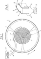
- Figure 1 only the mechanical resonator 2 of the mechanical movement of the timepiece, this resonator comprising a rocker 4 oscillating about a geometric axis 6 and a spiral 8 whose terminal curve 10 passes conventionally through a stud 12 secured to a balance bridge (not shown) of the mechanical movement.
- the Figure 2 schematically shows a portion of the spiral 8.
- This spiral is formed by a central body 14 of silicon, two side layers 16, 18 of piezoelectric material, in particular aluminum nitride (AlN), and two external metal electrodes 20, 22.
- the two electrodes are connected by conductive wires 26, 28 (schematic representation) to an electronic control circuit 24.
- the Figure 3 (which reproduces the figure 1 the previous document considered with some additional information from the figures 2 and 7 ) shows the general arrangement of the regulating device 32 which is incorporated in the timepiece in question and in particular the electronic control circuit 24.
- This circuit 24 comprises a first capacitor 34 connected to the two electrodes of the piezoelectric spiral and a plurality switchable capacitors 36a to 36d which are arranged in parallel with the first capacitor, so as to form a variable capacity Cv so as to be able to vary the value of the capacitance connected to the electrodes of the spiral and thus vary, according to the teaching of the document, the rigidity of the spiral.
- the circuit 24 further comprises a comparator 38 whose two inputs are respectively connected to the two electrodes of the spiral 8, this comparator being provided to provide a logic signal making it possible to determine, by successive changes in the logic state of this logic signal, the passages by zero of the voltage induced between the two electrodes of the spiral.
- the logic signal is supplied to a logic circuit 40 which also receives a reference signal from a clock circuit 42 associated with a crystal resonator 44. On the basis of a comparison between the reference signal and the logic signal provided speak comparator 38, the logic circuit 40 controls the switches of the switchable capacitors 36a to 36d.
- a full-wave rectifier circuit 46 conventionally formed of a four-diode bridge, which supplies a DC voltage V DC and charges a storage capacitor 48.
- This electrical energy supplied by the piezoelectric hairspring allows a supply of the device 32. It is therefore an autonomous electrical system because it is self-powered in that the electrical energy comes from the mechanical energy supplied to the mechanical resonator 2 including the piezoelectric spiral 8, when the resonator mechanical oscillates, forms an electromechanical transducer (an electric current generator).
- the electronic control circuit 24 can only reduce the oscillation frequency of the mechanical resonator 2 by increasing the value of the variable capacitance Cv.
- This finding is confirmed by the graph of the Figure 4 which shows the curve 50 giving the deviation as a function of the value of the variable capacitance Cv. It can be seen that the difference obtained is always less than zero and increases in absolute value as the value of the variable capacity increases.
- the control system requires that the natural frequency of the mechanical oscillator (frequency in the absence of regulation) is greater than the nominal frequency (reference frequency) of this mechanical oscillator.
- the present invention aims to propose a timepiece, provided with a mechanical resonator comprising a spiral formed at least partially of a piezoelectric material and an electronic control system associated with the piezoelectric spiral, which does not present the disadvantages of the timepiece of the prior art described above, in particular that can be associated with a mechanical movement whose gait is initially set optimally, that is to say to the best of its ability.
- the object of the invention is to provide an electronic control system which is discrete and autonomous thanks to the use of a piezoelectric spiral and which is really complementary to the mechanical movement by making it possible to increase its precision without degrading otherwise a optimal initial setting of this mechanical movement.
- the invention relates to a timepiece comprising a mechanical watch movement, provided with a mechanical oscillator formed by a balance and a hairspring and arranged to clock the movement of the watch movement, and a control device for regulating the frequency of the mechanical oscillator, said regulator comprising an auxiliary time base formed by an auxiliary oscillator and providing a reference frequency signal, and a device for measuring a time drift in the movement of the watch movement relative to a frequency set point for the mechanical oscillator which is determined by the auxiliary time base.
- the hairspring is formed at least partially by a piezoelectric material and by at least two electrodes arranged so as to be able to present between them an induced voltage generated by the material piezoelectric when the latter is placed under mechanical stress during an oscillation of the mechanical oscillator, the two electrodes being electrically connected to the regulating device which is arranged to be able to vary the impedance of the regulation system, formed by the piezoelectric material, said at least two electrodes and the regulating device, as a function of a measurement signal of the time drift provided by the measuring device.
- the regulating device is arranged in such a way as to be able to momentarily vary the electrical resistance generated by this regulating device between the two electrodes of the spiral and in order to be able to generate temporally separated regulation pulses, each consisting of a momentary decrease of this electrical resistance relative to a nominal electrical resistance which is generated by the regulating device between said two electrodes outside the regulation pulses.
- each of the aforementioned control pulses generates a gait deviation for the mechanical movement which is variable as a function of the instant of its beginning in a half-period of the mechanical oscillator.
- the regulating device is arranged to be able to determine whether a time drift measured by the measuring device corresponds to at least some advance or at least some delay and to generate at least one control pulse with a pulse start provided selectively , depending on whether the measured time drift corresponds to said at least some advance or at least a certain delay in said first time zone or in said second time zone of respectively at least one half-period of the mechanical oscillator.
- the characteristics of the timepiece according to the invention it is therefore possible to correct both an advance and a delay in the running of a mechanical movement by acting by regulation pulses, each having a limited duration, which vary the resistance between the two spiral electrodes in different time zones of corresponding half-periods according to whether an advance or a delay has been detected in the course of the mechanical movement.
- the regulating device comprises a switch arranged between the two electrodes of the spring, this switch being controlled by a control circuit which is arranged to momentarily close this switch so as to make it conductive during the control pulses. which then define short-circuit pulses.
- the timepiece according to the invention comprises, as the timepiece of the prior art described above, a mechanical watch movement provided with a mechanical oscillator formed by a balance and a piezoelectric spiral and arranged to clock the running of the movement watchmaker.
- the timepiece comprises a regulating device 62 whose electrical circuit diagram is shown in FIG. Figure 5 .
- This regulating device which is intended to regulate the frequency of the mechanical oscillator, comprises an electronic control circuit 52 and an auxiliary time base which is formed by an auxiliary oscillator and which supplies a reference frequency signal to the electronic circuit regulation.
- This time base comprises, for example, a quartz resonator 44 and a clock circuit 42 which supplies the reference frequency signal to a divider having at least two stages DIV1 and DIV2.
- the piezoelectric spiral 8 is formed at least partially by a piezoelectric material and by at least two electrodes 20, 22 (see FIG. Figures 2 , 5 and 11 ) which are arranged so as to be able to present between them an induced voltage U (t) by said piezoelectric material when the latter is subjected to mechanical stress during an oscillation of the mechanical oscillator (see FIG. Figure 7 ).
- the two electrodes are electrically connected to the electronic control circuit 52.
- the electronic control circuit comprises a device for measuring a possible time drift in the movement of the watch movement relative to a reference frequency for the mechanical oscillator which is determined by the auxiliary time base 42,44.
- the measurement device is formed by a hysteresis comparator 54 whose two inputs are connected to the two electrodes 20,22 of the piezoelectric coil 8. It will be noted that in the example given, the electrode 20 is electrically connected to an input of comparator 54 via the mass of the regulating device.
- the hysteresis comparator provides a digital 'Comp' signal (see Figures 5 and 7 ) whose logic state changes just after each passage of the mechanical oscillator by its neutral position (angular position ⁇ (t) equal to zero), more particularly after each zero crossing of the mechanical resonator forming the mechanical oscillator.
- the induced voltage U (t) generated by the piezoelectric spiral is zero during the passage of the mechanical resonator by its neutral position (angular position 'zero'), while it is maximum, for a given load applied between the two electrodes, when the mechanical resonator is in one or the other of its two extreme positions (defining the amplitude of the mechanical oscillator respectively on both sides of the neutral position).
- the signal 'Comp' is supplied, on the one hand, to a first input 'Up' of a bidirectional counter CB forming the measurement device and, on the other hand, to a control logic circuit 56.
- the bidirectional counter is thus incremented by one unit at each oscillation period of the mechanical oscillator. It therefore continuously receives a measurement of the instantaneous oscillation frequency of the mechanical oscillator.
- the bidirectional counter receives at its second input 'Down' a clock signal S hor supplied by the frequency divider DIV1 and DIV2, this clock signal defining a reference frequency for the mechanical oscillator which is determined by the oscillator auxiliary auxiliary time base.
- the bidirectional counter supplies the control logic circuit 56 with a signal corresponding to a cumulative error over time between the oscillation frequency of the mechanical oscillator and the reference frequency, this cumulative error defining the time drift of the oscillator. mechanical oscillator relative to the auxiliary oscillator.
- the regulating device is arranged in such a way as to be able to momentarily vary the electrical resistance generated by this regulating device between the two electrodes of the piezoelectric spiral as a function of a signal for measuring the time drift of the walking of the timepiece which is provided by a device for measuring this time drift. More particularly, the regulating device is arranged to be able to generate temporally separated regulation pulses and each consisting of a momentary reduction of the above-mentioned electrical resistance with respect to a nominal electrical resistance which is generated by the control device. regulation between the two electrodes outside the control pulses.
- the regulation device 62 comprises a switch 60 arranged between the two electrodes of the spring, this switch being controlled by the control logic circuit 56 which is arranged to momentarily close this switch so as to make it conductive during said control pulses, which then define short-circuit pulses.
- the abscissa of the graph of the Figure 6 corresponds to the time interval ⁇ t between the beginning of the short-circuit pulses in the respective oscillation periods and the beginning of the half-period considered in these oscillation periods.
- the deviation in seconds per day [s / d] is given according to the moment when the short-circuit pulses start on a half-period of 100 ms, between two successive passes of the mechanical resonator by its neutral position. during each of the successive oscillation periods.
- the short-circuit pulses each last 10 ms in the example shown, but this is not limiting.
- the electronic control circuit is arranged to be able to determine if a time drift measured by the measuring device corresponds to at least some advance (CB> N1) or at least some delay (CB ⁇ -N2), the state of the bidirectional counter CB being supplied to the control logic circuit 56 by the signal S DT which gives the state of the bidirectional counter.
- the regulating device is arranged to generate at least one control pulse with a selectively provided start, depending on whether the measured time drift corresponds to said at least some advance or audit at least some delay, in the first time zone ZT1 or in said second time zone ZT2 of respectively at least one half-period of the mechanical oscillator.
- a limited duration short-circuit pulse starting in the first time zone generates a certain delay for the mechanical oscillator (negative phase shift) which can correct at least partly a detected advance in the running of the timepiece
- a short-duration pulse of a limited duration beginning in the second time zone generates a certain advance for the mechanical oscillator (positive phase shift) which can correct at least partly a detected delay in the running of the piece of watchmaking.
- the Figures 9 and 10 show the graph of the induced voltage U (t) between the electrodes of the piezoelectric spiral during a short-circuit pulse beginning respectively at the instant ti in the first time zone ZT1 of any oscillation period and at the instant t 2 in the second time zone ZT2 of any oscillation period, respectively before and after a passage of the mechanical oscillator by an extreme position between two successive passages of this mechanical oscillator by its neutral position defining the half-period considered (see Figure 7 ).
- the regulation pulses each have a duration less than one quarter of the reference period which is equal to the inverse of said reference frequency for the mechanical oscillator.
- the duration of the regulation pulses is less than or equal to one-tenth of a set period. At most one control pulse is generated per half-period of the mechanical oscillator and preferably at most one regulation pulse per oscillation period. Then, the regulating device is arranged to generate at least one control pulse with a selectively provided start, depending on whether the measured time drift corresponds to at least some advance or at least some delay, in a first interval Int1 located at within the first time zone ZT1, for which the difference in direction given by said characteristic function 66 is greater, in absolute values, than at least half of a maximum deviation of this characteristic function on the first zone time, or in a second interval Int2 located within the second time zone ZT2 and for which the difference in direction given by the characteristic function is greater than at least half of a maximum deviation of this characteristic function on the second time zone.
- a relatively large effect is ensured during the control pulses, in particular during short-circuit pulses.
- a regulation method according to the invention is described which is implemented by the regulating device 62, this regulation method being in accordance with the characteristics of the invention previously described.
- the hysteresis comparator 54 supplies a signal 'Comp' to the control logic circuit 56, which also receives a signal S DT for measuring the time drift of the mechanical oscillator, and therefore of the timepiece considered .
- Each rising edge and each falling edge of the signal 'Comp' indicate that the mechanical resonator has just passed through its neutral position, respectively during two successive alternations of the mechanical oscillator.
- the control circuit selectively provides a control signal S com to a timer 58 which controls a transistor 60 forming the switch by applying a signal Dcc thereto.
- control circuit determines the instant of the beginning of each short-circuit pulse 88a, 88b by triggering or resetting the timer ('Timer') which directly turns on / off the transistor 60 (closed switch), the timer determining the duration T R of each short-circuit pulse.
- the timer opens the switch again so that the transistor 60 is no longer passing, that is to say non-conducting.
- the control logic circuit is associated with a time counter CT which makes it possible to measure at least two time intervals ⁇ t 1 and ⁇ t 2 in order to be able to selectively trigger the timer 58 in the first interval Int 1 and the second interval Int2 of one half-period, as considered in Figure 6 , depending on whether the control circuit has determined a certain advance or a certain delay, namely a positive or negative time drift, in the step of the mechanical oscillator. More precisely, when the control circuit detects in the signal 'Comp' a falling edge (or alternatively a rising edge), it resets ('reset') the counter CT.
- the control circuit waits a time interval ⁇ t 1 to activate the timer by a signal S com (1), this timer then generating a DC signal D (1) which turns transistor 60 on at time ti (in the first time zone ZT1, preferably in the first interval Int1) for a duration T R , thus generating a first short-circuit pulse 88a which generates a negative phase shift in the oscillation of the mechanical oscillator (increase of a period of oscillation and therefore decrease of the instantaneous frequency).
- the control circuit waits a time interval ⁇ t 2 to activate the timer by a signal S com (2), this timer then generates a DC signal D (2) which turns on transistor 60 at time t 2 (in the second time zone ZT2, preferably in the second interval Int2) also for a duration T R , thereby generating a second pulse of short circuit 88b which generates a positive phase shift in the oscillation of the mechanical oscillator (decrease of a period of oscillation / increase of the instantaneous frequency).
- the algorithm given by the organization chart of the Figure 8 can present various variants.
- a subsequence when a certain advance or a certain delay has been found, in which a plurality of short-circuit pulses are performed in a respective plurality of oscillation periods.
- the plurality of short-circuit pulses is carried out in successive oscillation periods or another variant in which these short-circuit pulses are periodically made every N oscillation periods.
- N being an integer greater than one (N> 1).
- This spiral 70 shown in cross section, comprises a central body 72 of silicon, a layer of silicon oxide 74 deposited on the surface of the central body so as to thermally compensate the spiral, a conductive layer 76 deposited on the silicon oxide layer, and a piezoelectric material deposited in the form of a piezoelectric layer 78 on the conductive layer 76.
- Two electrodes 20a and 22a are arranged on the piezoelectric layer 78 respectively of the two lateral sides of the hairspring (the two electrodes being able to partly cover the lower and upper sides of the hairspring without however joining).
- the first part 80a and the second part 80b of the piezoelectric layer respectively extending on the two lateral sides of the central body 72 have, by their growth from the conductive layer 76, respective crystallographic structures which are symmetrical with respect to a plane median 84 parallel to these two lateral sides.
- the piezoelectric layer has two same same piezoelectric axes 82a, 82b which are perpendicular to the piezoelectric layer and of opposite directions. There is therefore a reversal of the sign of the induced voltage between the internal electrode and each of the two external lateral electrodes for the same mechanical stress.
- the piezoelectric layer consists of an aluminum nitride crystal formed by a growth of this crystal from the conductive layer 76 (internal electrode) and perpendicular to it.
Landscapes
- Physics & Mathematics (AREA)
- General Physics & Mathematics (AREA)
- Engineering & Computer Science (AREA)
- Manufacturing & Machinery (AREA)
- Metallurgy (AREA)
- Oscillators With Electromechanical Resonators (AREA)
- Electric Clocks (AREA)
Abstract
La pièce d'horlogerie comprend un oscillateur mécanique, formé par un balancier et un spiral piézoélectrique (8), et un dispositif de régulation (62) pour réguler la fréquence de l'oscillateur mécanique qui est agencé pour pouvoir engendrer des impulsions de régulation (Dcc) temporellement séparées et consistant chacune en une diminution momentanée d'une résistance électrique appliquée par le dispositif de régulation entre deux électrodes (20, 22) du spiral relativement à une résistance électrique nominale. Chaque impulsion de régulation engendre un écart de marche qui est variable en fonction de l'instant de son début dans une demi-période de l'oscillateur mécanique, la fonction caractéristique de cet écart de marche relativement à l'instant où débute au moins une impulsion de régulation respectivement dans au moins une demi-période de l'oscillateur mécanique étant négative sur une première zone temporelle de ladite au moins une demi-période et positive sur une deuxième zone temporelle de ladite au moins une demi-période.The timepiece comprises a mechanical oscillator, formed by a balance and a piezoelectric spiral (8), and a regulating device (62) for regulating the frequency of the mechanical oscillator which is arranged to be able to generate regulation pulses ( Dcc) temporally separated and each consisting of a momentary reduction of an electrical resistance applied by the regulating device between two spiral electrodes (20, 22) relative to a nominal electrical resistance. Each regulation pulse generates a gait deviation which is variable as a function of the moment of its beginning in a half-period of the mechanical oscillator, the characteristic function of this difference of gait relative to the moment when at least one control pulse respectively in at least half a period of the mechanical oscillator being negative on a first time zone of said at least half a period and positive on a second time zone of said at least half a period.
Description
La présente invention concerne une pièce d'horlogerie comprenant un mouvement mécanique, muni d'un oscillateur mécanique qui est formé par un balancier et un spiral, et un dispositif électronique de régulation pour réguler la fréquence de l'oscillateur mécanique qui contrôle la marche du mouvement mécanique.The present invention relates to a timepiece comprising a mechanical movement, provided with a mechanical oscillator which is formed by a balance and a hairspring, and an electronic control device for regulating the frequency of the mechanical oscillator which controls the movement of the mechanical movement.
En particulier, le dispositif électronique de régulation comprend un oscillateur auxiliaire du type électronique généralement plus précis que l'oscillateur mécanique, en particulier un oscillateur à quartz, et un dispositif de mesure agencé pour pouvoir mesurer, le cas échéant, une dérive temporelle de l'oscillateur mécanique relativement à l'oscillateur auxiliaire.In particular, the electronic control device comprises an auxiliary oscillator of the electronic type that is generally more accurate than the mechanical oscillator, in particular a quartz oscillator, and a measuring device arranged to be able to measure, if necessary, a time drift of the oscillator. mechanical oscillator relative to the auxiliary oscillator.
Plusieurs documents concernent la régulation électronique d'un oscillateur mécanique dans une pièce d'horlogerie. En particulier, la demande de brevet
A l'aide des
La
De plus, il est prévu à la suite du circuit de capacités commutables un circuit redresseur double alternance 46, formé classiquement d'un pont à quatre diodes, qui fournit une tension continue VDC et charge une capacité de stockage 48. Cette énergie électrique fournie par le spiral piézoélectrique permet une alimentation du dispositif 32. On a donc un système électrique autonome car il est autoalimenté en ce sens que l'énergie électrique provient de l'énergie mécanique fournie au résonateur mécanique 2 dont le spiral piézoélectrique 8, lorsque le résonateur mécanique oscille, forme un transducteur électromécanique (un générateur de courant électrique).In addition, there is provided, following the switchable capacitance circuit, a full-
Comme indiqué dans le document
La présente invention a pour but de proposer une pièce d'horlogerie, munie d'un résonateur mécanique comprenant un spiral formé au moins partiellement d'un matériau piézoélectrique et d'un système de régulation électronique associé au spiral piézoélectrique, qui ne présente pas les inconvénients de la pièce d'horlogerie de l'art antérieur précédemment décrite, en particulier qui puisse être associé à un mouvement mécanique dont la marche est réglée initialement de manière optimale, c'est-à-dire au mieux de ses possibilités. Ainsi, l'invention a pour objectif de fournir un système de régulation électronique qui soit discret et autonome grâce à l'utilisation d'un spiral piézoélectrique et qui soit réellement complémentaire au mouvement mécanique en permettant d'augmenter sa précision sans dégrader par ailleurs un réglage initial optimal de ce mouvement mécanique.The present invention aims to propose a timepiece, provided with a mechanical resonator comprising a spiral formed at least partially of a piezoelectric material and an electronic control system associated with the piezoelectric spiral, which does not present the disadvantages of the timepiece of the prior art described above, in particular that can be associated with a mechanical movement whose gait is initially set optimally, that is to say to the best of its ability. Thus, the object of the invention is to provide an electronic control system which is discrete and autonomous thanks to the use of a piezoelectric spiral and which is really complementary to the mechanical movement by making it possible to increase its precision without degrading otherwise a optimal initial setting of this mechanical movement.
L'invention a pour objet une pièce d'horlogerie comprenant un mouvement horloger mécanique, muni d'un oscillateur mécanique formé par un balancier et un spiral et agencé pour cadencer la marche du mouvement horloger, et un dispositif de régulation pour réguler la fréquence de l'oscillateur mécanique, ce dispositif de régulation comprenant une base de temps auxiliaire, formée par un oscillateur auxiliaire et fournissant un signal de fréquence de référence, et un dispositif de mesure d'une dérive temporelle dans la marche du mouvement horloger relativement à une fréquence de consigne pour l'oscillateur mécanique qui est déterminée par la base de temps auxiliaire. Le spiral est formé au moins partiellement par un matériau piézoélectrique et par au moins deux électrodes agencées de manière à pouvoir présenter entre elles une tension induite générée par le matériau piézoélectrique lorsque ce dernier est mis sous contrainte mécanique lors d'une oscillation de l'oscillateur mécanique, les deux électrodes étant reliées électriquement au dispositif de régulation qui est agencé pour pouvoir varier l'impédance du système de régulation, formé par le matériau piézoélectrique, lesdites au moins deux électrodes et le dispositif de régulation, en fonction d'un signal de mesure de la dérive temporelle fourni par le dispositif de mesure. Plus particulièrement, selon l'invention, le dispositif de régulation est agencé de manière à pouvoir varier momentanément la résistance électrique engendrée par ce dispositif de régulation entre les deux électrodes du spiral et pour pouvoir engendrer des impulsions de régulation temporellement séparées et consistant chacune en une diminution momentanée de cette résistance électrique relativement à une résistance électrique nominale qui est engendrée par le dispositif de régulation entre lesdites deux électrodes en dehors des impulsions de régulation. Selon une caractéristique physique remarquable mise en lumière par les inventeurs, chacune des impulsions de régulation susmentionnées engendre un écart de marche pour le mouvement mécanique qui est variable en fonction de l'instant de son début dans une demi-période de l'oscillateur mécanique, la fonction caractéristique de cet écart de marche relativement à l'instant où débute au moins une impulsion de régulation respectivement dans au moins une demi-période de l'oscillateur mécanique étant négative sur une première zone temporelle de cette au moins une demi-période et positive sur une deuxième zone temporelle de cette au moins une demi-période. Le dispositif de régulation est agencé pour pouvoir déterminer si une dérive temporelle mesurée par le dispositif de mesure correspond à au moins une certaine avance ou à au moins un certain retard et pour engendrer au moins une impulsion de régulation avec un début d'impulsion prévu sélectivement, selon que la dérive temporelle mesurée correspond à ladite au moins une certaine avance ou audit au moins un certain retard, dans ladite première zone temporelle ou dans ladite deuxième zone temporelle de respectivement au moins une demi-période de l'oscillateur mécanique.The invention relates to a timepiece comprising a mechanical watch movement, provided with a mechanical oscillator formed by a balance and a hairspring and arranged to clock the movement of the watch movement, and a control device for regulating the frequency of the mechanical oscillator, said regulator comprising an auxiliary time base formed by an auxiliary oscillator and providing a reference frequency signal, and a device for measuring a time drift in the movement of the watch movement relative to a frequency set point for the mechanical oscillator which is determined by the auxiliary time base. The hairspring is formed at least partially by a piezoelectric material and by at least two electrodes arranged so as to be able to present between them an induced voltage generated by the material piezoelectric when the latter is placed under mechanical stress during an oscillation of the mechanical oscillator, the two electrodes being electrically connected to the regulating device which is arranged to be able to vary the impedance of the regulation system, formed by the piezoelectric material, said at least two electrodes and the regulating device, as a function of a measurement signal of the time drift provided by the measuring device. More particularly, according to the invention, the regulating device is arranged in such a way as to be able to momentarily vary the electrical resistance generated by this regulating device between the two electrodes of the spiral and in order to be able to generate temporally separated regulation pulses, each consisting of a momentary decrease of this electrical resistance relative to a nominal electrical resistance which is generated by the regulating device between said two electrodes outside the regulation pulses. According to a remarkable physical characteristic brought to light by the inventors, each of the aforementioned control pulses generates a gait deviation for the mechanical movement which is variable as a function of the instant of its beginning in a half-period of the mechanical oscillator. the characteristic function of this difference in operation relative to the moment when at least one control pulse respectively starts in at least half a period of the mechanical oscillator being negative on a first time zone of this at least half a period and positive on a second time zone of this at least half a period. The regulating device is arranged to be able to determine whether a time drift measured by the measuring device corresponds to at least some advance or at least some delay and to generate at least one control pulse with a pulse start provided selectively , depending on whether the measured time drift corresponds to said at least some advance or at least a certain delay in said first time zone or in said second time zone of respectively at least one half-period of the mechanical oscillator.
Grâce aux caractéristiques de la pièce d'horlogerie selon l'invention, il est donc possible de corriger aussi bien une avance qu'un retard dans la marche d'un mouvement mécanique en agissant par des impulsions de régulation, ayant chacune une durée limitée, qui varient la résistance entre les deux électrodes du spiral dans des zones temporelles différentes de demi-périodes correspondantes selon qu'une avance ou un retard a été détecté dans la marche du mouvement mécanique.Thanks to the characteristics of the timepiece according to the invention, it is therefore possible to correct both an advance and a delay in the running of a mechanical movement by acting by regulation pulses, each having a limited duration, which vary the resistance between the two spiral electrodes in different time zones of corresponding half-periods according to whether an advance or a delay has been detected in the course of the mechanical movement.
Dans un mode de réalisation préféré, le dispositif de régulation comprend un interrupteur agencé entre les deux électrodes du spiral, cet interrupteur étant commandé par un circuit de commande qui est agencé pour fermer momentanément cet interrupteur de manière à le rendre conducteur durant les impulsions de régulation, lesquelles définissent alors des impulsions de court-circuit.In a preferred embodiment, the regulating device comprises a switch arranged between the two electrodes of the spring, this switch being controlled by a control circuit which is arranged to momentarily close this switch so as to make it conductive during the control pulses. which then define short-circuit pulses.
L'invention sera décrite ci-après de manière plus détaillée à l'aide des dessins annexés, donnés à titre d'exemples nullement limitatifs, dans lesquels :
- La
Figure 1 , déjà décrite, montre une pièce d'horlogerie de l'art antérieur comprenant un résonateur mécanique horloger, ayant un spiral piézoélectrique, et un circuit électronique de régulation qui est relié aux deux électrodes du spiral piézoélectrique ; - La
Figure 2 est un agrandissement d'une portion du spiral piézoélectrique de laFigure 1 ; - La
Figure 3 montre partiellement le schéma électrique du dispositif de régulation de la pièce d'horlogerie de laFigure 1 ; - La
Figure 4 donne l'écart de marche pour la pièce d'horlogerie des figures précédentes en fonction d'une capacité variable appliquée entre les deux électrodes du spiral piézoélectrique ; - La
Figure 5 montre le schéma électrique d'un dispositif de régulation incorporé dans un mode de réalisation d'une pièce d'horlogerie selon l'invention qui comprend un résonateur mécanique avec un spiral piézoélectrique ; - La
Figure 6 montre l'écart de marche par jour, pour la pièce d'horlogerie selon l'invention, qui est engendré par le dispositif de régulation de laFigure 5 en fonction du début d'impulsions de court-circuit, au cours de périodes d'oscillation respectives, sur une demi-période entre deux passages par la position neutre du résonateur mécanique dans chacune de ces périodes d'oscillation ; - La
Figure 7 montre un mode de génération des impulsions de court-circuit dans le dispositif de régulation de laFigure 5 en fonction d'une dérive temporelle mesurée dans la marche de la pièce d'horlogerie ; - La
Figure 8 est un organigramme d'un procédé de régulation implémenté dans le dispositif de régulation de laFigure 5 ; - Les
Figures 9 et 10 montrent le graphe de la tension induite entre les électrodes du spiral piézoélectrique lors d'une impulsion de court-circuit produite respectivement avant et après un passage du résonateur mécanique par une position extrême (entre deux passages successifs du résonateur mécanique par sa position neutre) ; et - La
Figure 11 est une coupe transversale d'un mode de réalisation préféré d'un spiral piézoélectrique formant le résonateur mécanique d'une pièce d'horlogerie selon l'invention.
- The
Figure 1 , already described, shows a timepiece of the prior art comprising a clock mechanical resonator, having a piezoelectric spiral, and an electronic control circuit which is connected to the two electrodes of the piezoelectric spiral; - The
Figure 2 is an enlargement of a portion of the piezoelectric spiral of theFigure 1 ; - The
Figure 3 partially shows the electrical diagram of the control device of the timepiece of theFigure 1 ; - The
Figure 4 gives the time difference for the timepiece of the preceding figures as a function of a variable capacitance applied between the two electrodes of the piezoelectric spiral; - The
Figure 5 shows the electrical diagram of a control device incorporated in an embodiment of a timepiece according to the invention which comprises a mechanical resonator with a piezoelectric spiral; - The
Figure 6 shows the time difference per day, for the timepiece according to the invention, which is generated by the control device of theFigure 5 as a function of the beginning of short-circuit pulses, during respective oscillation periods, over a half-period between two passages by the neutral position of the mechanical resonator in each of these oscillation periods; - The
Figure 7 shows a mode of generating the short-circuit pulses in the control device of theFigure 5 according to a time drift measured in the running of the timepiece; - The
Figure 8 is a flowchart of a control method implemented in the control device of theFigure 5 ; - The
Figures 9 and 10 show the graph of the induced voltage between the electrodes of the piezoelectric spiral during a short-circuit pulse produced respectively before and after a passage of the mechanical resonator by an extreme position (between two successive passages of the mechanical resonator by its neutral position); and - The
Figure 11 is a cross section of a preferred embodiment of a piezoelectric spiral forming the mechanical resonator of a timepiece according to the invention.
La pièce d'horlogerie selon l'invention comprend, comme la pièce d'horlogerie de l'art antérieur décrite précédemment, un mouvement horloger mécanique muni d'un oscillateur mécanique formé par un balancier et un spiral piézoélectrique et agencé pour cadencer la marche du mouvement horloger. Ensuite, la pièce d'horlogerie comprend un dispositif de régulation 62 dont le schéma électrique est représenté à la
Le circuit électronique de régulation comprend un dispositif de mesure d'une dérive temporelle éventuelle dans la marche du mouvement horloger relativement à une fréquence de consigne pour l'oscillateur mécanique qui est déterminée par la base de temps auxiliaire 42,44. Dans le mode de réalisation représenté à la
Le signal 'Comp' est fourni, d'une part, à une première entrée 'Up' d'un compteur bidirectionnel CB formant le dispositif de mesure et, d'autre part, à un circuit logique de commande 56. Le compteur bidirectionnel est ainsi incrémenté d'une unité à chaque période d'oscillation de l'oscillateur mécanique. Il reçoit donc en continu une mesure de la fréquence d'oscillation instantanée de l'oscillateur mécanique. Le compteur bidirectionnel reçoit à sa deuxième entrée 'Down' un signal d'horloge Shor fourni par le diviseur de fréquence DIV1 et DIV2, ce signal d'horloge définissant une fréquence de consigne pour l'oscillateur mécanique qui est déterminée par l'oscillateur auxiliaire de la base de temps auxiliaire. Ainsi, le compteur bidirectionnel fournit au circuit logique de commande 56 un signal correspondant à une erreur cumulée au cours du temps entre la fréquence d'oscillation de l'oscillateur mécanique et la fréquence de consigne, cette erreur cumulée définissant la dérive temporelle de l'oscillateur mécanique relativement à l'oscillateur auxiliaire.The signal 'Comp' is supplied, on the one hand, to a first input 'Up' of a bidirectional counter CB forming the measurement device and, on the other hand, to a
De manière générale, le dispositif de régulation selon l'invention est agencé de manière à pouvoir varier momentanément la résistance électrique engendrée par ce dispositif de régulation entre les deux électrodes du spiral piézoélectrique en fonction d'un signal de mesure de la dérive temporelle de la marche de la pièce d'horlogerie qui est fourni par un dispositif de mesure de cette dérive temporelle. Plus particulièrement, le dispositif de régulation est agencé pour pouvoir engendrer des impulsions de régulation temporellement séparées et consistant chacune en une diminution momentanée de la résistance électrique susmentionnée relativement à une résistance électrique nominale qui est engendrée par le dispositif de régulation entre les deux électrodes en dehors des impulsions de régulation. Ainsi, on a un système de régulation de la marche de la pièce d'horlogerie, et donc de la fréquence moyenne de l'oscillateur mécanique, qui est formé par le matériau piézoélectrique du spiral 8, les deux électrodes 20,22 de ce spiral et le dispositif de régulation selon l'invention.In general, the regulating device according to the invention is arranged in such a way as to be able to momentarily vary the electrical resistance generated by this regulating device between the two electrodes of the piezoelectric spiral as a function of a signal for measuring the time drift of the walking of the timepiece which is provided by a device for measuring this time drift. More particularly, the regulating device is arranged to be able to generate temporally separated regulation pulses and each consisting of a momentary reduction of the above-mentioned electrical resistance with respect to a nominal electrical resistance which is generated by the control device. regulation between the two electrodes outside the control pulses. Thus, there is a system for regulating the step of the timepiece, and therefore of the average frequency of the mechanical oscillator, which is formed by the piezoelectric material of the
Dans un mode de réalisation préféré, le dispositif de régulation 62 comprend un interrupteur 60 agencé entre les deux électrodes du spiral, cet interrupteur étant commandé par le circuit logique de commande 56 qui est agencé pour fermer momentanément cet interrupteur de manière à le rendre conducteur durant lesdites impulsions de régulation, lesquelles définissent alors des impulsions de court-circuit.In a preferred embodiment, the
Dans le cadre de l'invention, les inventeurs ont mis en lumière que les impulsions de régulation mentionnées précédemment engendrent chacune un écart de marche pour le mouvement mécanique qui est variable en fonction de l'instant du début de l'impulsion de régulation considérée dans une demi-période de l'oscillateur mécanique. Cette observation est représentée à la
Le circuit électronique de régulation est agencé pour pouvoir déterminer si une dérive temporelle mesurée par le dispositif de mesure correspond à au moins une certaine avance (CB > N1) ou à au moins un certain retard (CB < -N2), l'état du compteur bidirectionnel CB étant fourni au circuit logique de commande 56 par le signal SDT qui donne l'état du compteur bidirectionnel. Le dispositif de régulation est agencé pour engendrer au moins une impulsion de régulation avec un début prévu sélectivement, selon que la dérive temporelle mesurée correspond à ladite au moins une certaine avance ou audit au moins un certain retard, dans la première zone temporelle ZT1 ou dans ladite deuxième zone temporelle ZT2 de respectivement au moins une demi-période de l'oscillateur mécanique. En effet, une impulsion de court-circuit de durée limitée débutant dans la première zone temporelle engendre un certain retard pour l'oscillateur mécanique (déphasage négatif) qui peut corriger au moins en partie une avance détectée dans la marche de la pièce d'horlogerie, alors qu'une impulsion de court-circuit de durée limitée débutant dans la deuxième zone temporelle engendre une certaine avance pour l'oscillateur mécanique (déphasage positif) qui peut corriger au moins en partie un retard détecté dans la marche de la pièce d'horlogerie.The electronic control circuit is arranged to be able to determine if a time drift measured by the measuring device corresponds to at least some advance (CB> N1) or at least some delay (CB <-N2), the state of the bidirectional counter CB being supplied to the
Les
Dans une variante générale, les impulsions de régulation ont chacune une durée inférieure au quart de la période de consigne qui est égale à l'inverse de ladite fréquence de consigne pour l'oscillateur mécanique.In a general variant, the regulation pulses each have a duration less than one quarter of the reference period which is equal to the inverse of said reference frequency for the mechanical oscillator.
Dans une variante de réalisation préférée, la durée des impulsions de régulation est inférieure ou égale à un dixième d'une période de consigne. Au plus une impulsion de régulation est engendrée par demi-période de l'oscillateur mécanique et de préférence au plus une impulsion de régulation par période d'oscillation. Ensuite, le dispositif de régulation est agencé pour engendrer au moins une impulsion de régulation avec un début prévu sélectivement, selon que la dérive temporelle mesurée correspond à au moins une certaine avance ou à au moins un certain retard, dans un premier intervalle Int1 situé à l'intérieur de la première zone temporelle ZT1, pour lequel l'écart de marche donné par ladite fonction caractéristique 66 est supérieur, en valeurs absolues, à au moins la moitié d'un écart de marche maximal de cette fonction caractéristique sur la première zone temporelle, ou dans un deuxième intervalle Int2 situé à l'intérieur de la deuxième zone temporelle ZT2 et pour lequel l'écart de marche donné par la fonction caractéristique est supérieur à au moins la moitié d'un écart de marche maximal de cette fonction caractéristique sur la deuxième zone temporelle. Ainsi, on assure un effet relativement important lors des impulsions de régulation, en particulier lors des impulsions de court-circuit.In a preferred embodiment variant, the duration of the regulation pulses is less than or equal to one-tenth of a set period. At most one control pulse is generated per half-period of the mechanical oscillator and preferably at most one regulation pulse per oscillation period. Then, the regulating device is arranged to generate at least one control pulse with a selectively provided start, depending on whether the measured time drift corresponds to at least some advance or at least some delay, in a first interval Int1 located at within the first time zone ZT1, for which the difference in direction given by said
En référence aux
En exploitant la fonction caractéristique 66 décrite précédemment, le circuit logique de commande est associé à un compteur temporelle CT qui permet de mesurer au moins deux intervalles de temps Δt1 et Δt2 pour pouvoir déclencher sélectivement le minuteur 58 dans le premier intervalle Int1 et le deuxième intervalle Int2 d'une demi-période, telle que considérée à la
On notera que l'algorithme donné par l'organigramme de la
A l'aide de la
Dans la variante particulière représentée à la
Claims (7)
Priority Applications (4)
| Application Number | Priority Date | Filing Date | Title |
|---|---|---|---|
| EP18162191.3A EP3540528B1 (en) | 2018-03-16 | 2018-03-16 | Timepiece comprising a mechanical movement the oscillating rate of which is controlled by an electronic device |
| JP2019042361A JP6797227B2 (en) | 2018-03-16 | 2019-03-08 | A timekeeper with a mechanical movement whose speed is controlled by an electronic device |
| CN201910193381.2A CN110275420B (en) | 2018-03-16 | 2019-03-14 | Timepiece comprising a mechanical movement and an electronic device for adjusting the rate of the movement |
| US16/354,217 US11415946B2 (en) | 2018-03-16 | 2019-03-15 | Timepiece comprising a mechanical movement whose rate is regulated by an electronic device |
Applications Claiming Priority (1)
| Application Number | Priority Date | Filing Date | Title |
|---|---|---|---|
| EP18162191.3A EP3540528B1 (en) | 2018-03-16 | 2018-03-16 | Timepiece comprising a mechanical movement the oscillating rate of which is controlled by an electronic device |
Publications (2)
| Publication Number | Publication Date |
|---|---|
| EP3540528A1 true EP3540528A1 (en) | 2019-09-18 |
| EP3540528B1 EP3540528B1 (en) | 2020-08-05 |
Family
ID=61691302
Family Applications (1)
| Application Number | Title | Priority Date | Filing Date |
|---|---|---|---|
| EP18162191.3A Active EP3540528B1 (en) | 2018-03-16 | 2018-03-16 | Timepiece comprising a mechanical movement the oscillating rate of which is controlled by an electronic device |
Country Status (4)
| Country | Link |
|---|---|
| US (1) | US11415946B2 (en) |
| EP (1) | EP3540528B1 (en) |
| JP (1) | JP6797227B2 (en) |
| CN (1) | CN110275420B (en) |
Cited By (2)
| Publication number | Priority date | Publication date | Assignee | Title |
|---|---|---|---|---|
| EP4099100A1 (en) | 2021-06-02 | 2022-12-07 | The Swatch Group Research and Development Ltd | Timepiece movement provided with an oscillator comprising a piezoelectric hairspring |
| EP4130890A1 (en) | 2021-08-04 | 2023-02-08 | The Swatch Group Research and Development Ltd | Timepiece movement provided with an oscillator comprising a piezoelectric hairspring |
Families Citing this family (1)
| Publication number | Priority date | Publication date | Assignee | Title |
|---|---|---|---|---|
| EP3629103B1 (en) * | 2018-09-28 | 2021-05-12 | The Swatch Group Research and Development Ltd | Timepiece comprising a mechanical movement of which the oscillation precision is regulated by an electronic device |
Citations (6)
| Publication number | Priority date | Publication date | Assignee | Title |
|---|---|---|---|---|
| EP1164441A1 (en) * | 1999-12-24 | 2001-12-19 | Seiko Instruments Inc. | Mechanical timepiece having train wheel operation controller |
| US20130051191A1 (en) | 2010-04-21 | 2013-02-28 | Team Smartfish Gmbh | Controller for a clockwork mechanism, and corresponding method |
| EP2590035A1 (en) * | 2011-11-01 | 2013-05-08 | The Swatch Group Research and Development Ltd. | Circuit for self-regulating the oscillation frequency of an oscillating mechanical system and device including same |
| US20150051191A1 (en) | 2013-08-15 | 2015-02-19 | Medicinova, Inc. | Treatment of alcoholism using ibudilast |
| CH709279A2 (en) * | 2014-02-17 | 2015-08-28 | Swatch Group Res & Dev Ltd | Regulation of a clockwork resonator by acting on the rigidity of an elastic return means. |
| CH710603A2 (en) * | 2015-01-09 | 2016-07-15 | Sigatec Sa | Clock spring spiral clock adjustable frequency. |
Family Cites Families (10)
| Publication number | Priority date | Publication date | Assignee | Title |
|---|---|---|---|---|
| CH568597B5 (en) * | 1971-12-10 | 1975-10-31 | Dixi Sa | |
| JPS4996771A (en) * | 1972-11-10 | 1974-09-12 | ||
| US4340948A (en) * | 1980-04-24 | 1982-07-20 | General Time Corporation | Single-coil balance wheel for driving a mechanical movement |
| JP3767388B2 (en) * | 2001-01-30 | 2006-04-19 | セイコーエプソン株式会社 | Piezoelectric governor and electronic device using the piezoelectric governor |
| EP1605323A3 (en) * | 2004-04-13 | 2006-07-12 | Coredem S.A. | Spiral spring for mechanical clockwork |
| JP4692967B2 (en) * | 2006-01-27 | 2011-06-01 | セイコーインスツル株式会社 | Calendar clock with two date wheels arranged eccentrically |
| EP2104008A1 (en) * | 2008-03-20 | 2009-09-23 | Nivarox-FAR S.A. | Single-body regulating organ and method for manufacturing same |
| CH704693B1 (en) * | 2010-07-16 | 2015-08-14 | Eta Sa Manufacture Horlogère Suisse | A method of adjusting the oscillation frequency, and / or adjusting the inertia, and / or balancing a movable component of a clockwork movement, or a clockwork balance-spring assembly. |
| CH705679B1 (en) * | 2011-10-28 | 2017-01-31 | Swatch Group Res & Dev Ltd | A circuit for self-regulating the oscillation frequency of an oscillating mechanical system, and a device comprising the same. |
| EP3252545B1 (en) * | 2016-06-03 | 2019-10-16 | The Swatch Group Research and Development Ltd. | Timepiece mechanism with balance wheel inertia adjustment |
-
2018
- 2018-03-16 EP EP18162191.3A patent/EP3540528B1/en active Active
-
2019
- 2019-03-08 JP JP2019042361A patent/JP6797227B2/en active Active
- 2019-03-14 CN CN201910193381.2A patent/CN110275420B/en active Active
- 2019-03-15 US US16/354,217 patent/US11415946B2/en active Active
Patent Citations (6)
| Publication number | Priority date | Publication date | Assignee | Title |
|---|---|---|---|---|
| EP1164441A1 (en) * | 1999-12-24 | 2001-12-19 | Seiko Instruments Inc. | Mechanical timepiece having train wheel operation controller |
| US20130051191A1 (en) | 2010-04-21 | 2013-02-28 | Team Smartfish Gmbh | Controller for a clockwork mechanism, and corresponding method |
| EP2590035A1 (en) * | 2011-11-01 | 2013-05-08 | The Swatch Group Research and Development Ltd. | Circuit for self-regulating the oscillation frequency of an oscillating mechanical system and device including same |
| US20150051191A1 (en) | 2013-08-15 | 2015-02-19 | Medicinova, Inc. | Treatment of alcoholism using ibudilast |
| CH709279A2 (en) * | 2014-02-17 | 2015-08-28 | Swatch Group Res & Dev Ltd | Regulation of a clockwork resonator by acting on the rigidity of an elastic return means. |
| CH710603A2 (en) * | 2015-01-09 | 2016-07-15 | Sigatec Sa | Clock spring spiral clock adjustable frequency. |
Cited By (2)
| Publication number | Priority date | Publication date | Assignee | Title |
|---|---|---|---|---|
| EP4099100A1 (en) | 2021-06-02 | 2022-12-07 | The Swatch Group Research and Development Ltd | Timepiece movement provided with an oscillator comprising a piezoelectric hairspring |
| EP4130890A1 (en) | 2021-08-04 | 2023-02-08 | The Swatch Group Research and Development Ltd | Timepiece movement provided with an oscillator comprising a piezoelectric hairspring |
Also Published As
| Publication number | Publication date |
|---|---|
| CN110275420A (en) | 2019-09-24 |
| JP2019158882A (en) | 2019-09-19 |
| US20190286063A1 (en) | 2019-09-19 |
| JP6797227B2 (en) | 2020-12-09 |
| EP3540528B1 (en) | 2020-08-05 |
| CN110275420B (en) | 2020-11-27 |
| US11415946B2 (en) | 2022-08-16 |
Similar Documents
| Publication | Publication Date | Title |
|---|---|---|
| EP3629103B1 (en) | Timepiece comprising a mechanical movement of which the oscillation precision is regulated by an electronic device | |
| EP3540528B1 (en) | Timepiece comprising a mechanical movement the oscillating rate of which is controlled by an electronic device | |
| EP3629104B1 (en) | Mechanical timepiece comprising an electronic device for regulating the time keeping precision of the timepiece | |
| EP3620867A1 (en) | Timepiece comprising a mechanical oscillator whose average frequency is synchronised to that of a reference electronic oscillator | |
| EP0171635A1 (en) | Method and apparatus to recognise the position of the rotor of a stepping motor | |
| EP3457223A1 (en) | Piezoelectric element for a frequency self-regulation circuit, and oscillating mechanical system and device including the same | |
| CH713306A2 (en) | Watchmaking assembly comprising a mechanical oscillator associated with a device for regulating its average frequency. | |
| CH714794A2 (en) | Timepiece comprising a mechanical movement whose movement is regulated by an electronic device. | |
| EP3502797B1 (en) | Timepiece comprising a mechanical oscillator associated with a control system | |
| EP3502796B1 (en) | Timepiece comprising a mechanical oscillator associated with a control system | |
| EP3457224B1 (en) | Piezoelectric element for a frequency self-regulation circuit, oscillating mechanical system and device including the same, and method for manufacturing the piezoelectric element | |
| EP4099100A1 (en) | Timepiece movement provided with an oscillator comprising a piezoelectric hairspring | |
| CH715392A2 (en) | Timepiece comprising a mechanical movement, the progress of which is regulated by an electronic device. | |
| EP3502798B1 (en) | Timepiece comprising a mechanical oscillator associated with a control system | |
| EP2590035A1 (en) | Circuit for self-regulating the oscillation frequency of an oscillating mechanical system and device including same | |
| CH715399A2 (en) | Timepiece comprising a mechanical oscillator associated with an electronic device for regulating its average frequency. | |
| EP4130890B1 (en) | Timepiece movement provided with an oscillator comprising a piezoelectric hairspring | |
| CH718897A2 (en) | Watch movement equipped with an oscillator comprising a piezoelectric hairspring. | |
| CH718689A2 (en) | Watch movement fitted with an oscillator comprising a piezoelectric hairspring. | |
| EP0371256B1 (en) | Apparatus for measuring a physical quantity | |
| EP4009119A1 (en) | Timepiece movement provided with a generator and a circuit for controlling the frequency of rotation of said generator | |
| EP0848306B1 (en) | Time piece having an electric energy generator | |
| CH718138A2 (en) | Clock movement equipped with a generator and a circuit for regulating the frequency of rotation of this generator. | |
| CH715295A2 (en) | Timepiece including a mechanical oscillator whose average frequency is synchronized with that of a reference electronic oscillator. | |
| CH714143A2 (en) | Piezoelectric element for a frequency self-regulating circuit, and oscillating mechanical system and device comprising same. |
Legal Events
| Date | Code | Title | Description |
|---|---|---|---|
| PUAI | Public reference made under article 153(3) epc to a published international application that has entered the european phase |
Free format text: ORIGINAL CODE: 0009012 |
|
| STAA | Information on the status of an ep patent application or granted ep patent |
Free format text: STATUS: THE APPLICATION HAS BEEN PUBLISHED |
|
| AK | Designated contracting states |
Kind code of ref document: A1 Designated state(s): AL AT BE BG CH CY CZ DE DK EE ES FI FR GB GR HR HU IE IS IT LI LT LU LV MC MK MT NL NO PL PT RO RS SE SI SK SM TR |
|
| AX | Request for extension of the european patent |
Extension state: BA ME |
|
| STAA | Information on the status of an ep patent application or granted ep patent |
Free format text: STATUS: REQUEST FOR EXAMINATION WAS MADE |
|
| 17P | Request for examination filed |
Effective date: 20200318 |
|
| GRAP | Despatch of communication of intention to grant a patent |
Free format text: ORIGINAL CODE: EPIDOSNIGR1 |
|
| RBV | Designated contracting states (corrected) |
Designated state(s): AL AT BE BG CH CY CZ DE DK EE ES FI FR GB GR HR HU IE IS IT LI LT LU LV MC MK MT NL NO PL PT RO RS SE SI SK SM TR |
|
| STAA | Information on the status of an ep patent application or granted ep patent |
Free format text: STATUS: GRANT OF PATENT IS INTENDED |
|
| INTG | Intention to grant announced |
Effective date: 20200423 |
|
| RIN1 | Information on inventor provided before grant (corrected) |
Inventor name: NAGY, LAURENT Inventor name: HAEMMERLI, ALEXANDRE Inventor name: TOMBEZ, LIONEL |
|
| GRAS | Grant fee paid |
Free format text: ORIGINAL CODE: EPIDOSNIGR3 |
|
| GRAA | (expected) grant |
Free format text: ORIGINAL CODE: 0009210 |
|
| STAA | Information on the status of an ep patent application or granted ep patent |
Free format text: STATUS: THE PATENT HAS BEEN GRANTED |
|
| AK | Designated contracting states |
Kind code of ref document: B1 Designated state(s): AL AT BE BG CH CY CZ DE DK EE ES FI FR GB GR HR HU IE IS IT LI LT LU LV MC MK MT NL NO PL PT RO RS SE SI SK SM TR |
|
| REG | Reference to a national code |
Ref country code: GB Ref legal event code: FG4D Free format text: NOT ENGLISH |
|
| REG | Reference to a national code |
Ref country code: CH Ref legal event code: EP |
|
| REG | Reference to a national code |
Ref country code: AT Ref legal event code: REF Ref document number: 1299575 Country of ref document: AT Kind code of ref document: T Effective date: 20200815 |
|
| REG | Reference to a national code |
Ref country code: DE Ref legal event code: R096 Ref document number: 602018006541 Country of ref document: DE |
|
| REG | Reference to a national code |
Ref country code: CH Ref legal event code: NV Representative=s name: ICB INGENIEURS CONSEILS EN BREVETS SA, CH |
|
| REG | Reference to a national code |
Ref country code: IE Ref legal event code: FG4D Free format text: LANGUAGE OF EP DOCUMENT: FRENCH |
|
| REG | Reference to a national code |
Ref country code: LT Ref legal event code: MG4D |
|
| REG | Reference to a national code |
Ref country code: NL Ref legal event code: MP Effective date: 20200805 |
|
| REG | Reference to a national code |
Ref country code: AT Ref legal event code: MK05 Ref document number: 1299575 Country of ref document: AT Kind code of ref document: T Effective date: 20200805 |
|
| PG25 | Lapsed in a contracting state [announced via postgrant information from national office to epo] |
Ref country code: FI Free format text: LAPSE BECAUSE OF FAILURE TO SUBMIT A TRANSLATION OF THE DESCRIPTION OR TO PAY THE FEE WITHIN THE PRESCRIBED TIME-LIMIT Effective date: 20200805 Ref country code: SE Free format text: LAPSE BECAUSE OF FAILURE TO SUBMIT A TRANSLATION OF THE DESCRIPTION OR TO PAY THE FEE WITHIN THE PRESCRIBED TIME-LIMIT Effective date: 20200805 Ref country code: NO Free format text: LAPSE BECAUSE OF FAILURE TO SUBMIT A TRANSLATION OF THE DESCRIPTION OR TO PAY THE FEE WITHIN THE PRESCRIBED TIME-LIMIT Effective date: 20201105 Ref country code: ES Free format text: LAPSE BECAUSE OF FAILURE TO SUBMIT A TRANSLATION OF THE DESCRIPTION OR TO PAY THE FEE WITHIN THE PRESCRIBED TIME-LIMIT Effective date: 20200805 Ref country code: GR Free format text: LAPSE BECAUSE OF FAILURE TO SUBMIT A TRANSLATION OF THE DESCRIPTION OR TO PAY THE FEE WITHIN THE PRESCRIBED TIME-LIMIT Effective date: 20201106 Ref country code: PT Free format text: LAPSE BECAUSE OF FAILURE TO SUBMIT A TRANSLATION OF THE DESCRIPTION OR TO PAY THE FEE WITHIN THE PRESCRIBED TIME-LIMIT Effective date: 20201207 Ref country code: AT Free format text: LAPSE BECAUSE OF FAILURE TO SUBMIT A TRANSLATION OF THE DESCRIPTION OR TO PAY THE FEE WITHIN THE PRESCRIBED TIME-LIMIT Effective date: 20200805 Ref country code: HR Free format text: LAPSE BECAUSE OF FAILURE TO SUBMIT A TRANSLATION OF THE DESCRIPTION OR TO PAY THE FEE WITHIN THE PRESCRIBED TIME-LIMIT Effective date: 20200805 Ref country code: LT Free format text: LAPSE BECAUSE OF FAILURE TO SUBMIT A TRANSLATION OF THE DESCRIPTION OR TO PAY THE FEE WITHIN THE PRESCRIBED TIME-LIMIT Effective date: 20200805 Ref country code: BG Free format text: LAPSE BECAUSE OF FAILURE TO SUBMIT A TRANSLATION OF THE DESCRIPTION OR TO PAY THE FEE WITHIN THE PRESCRIBED TIME-LIMIT Effective date: 20201105 |
|
| PG25 | Lapsed in a contracting state [announced via postgrant information from national office to epo] |
Ref country code: NL Free format text: LAPSE BECAUSE OF FAILURE TO SUBMIT A TRANSLATION OF THE DESCRIPTION OR TO PAY THE FEE WITHIN THE PRESCRIBED TIME-LIMIT Effective date: 20200805 Ref country code: PL Free format text: LAPSE BECAUSE OF FAILURE TO SUBMIT A TRANSLATION OF THE DESCRIPTION OR TO PAY THE FEE WITHIN THE PRESCRIBED TIME-LIMIT Effective date: 20200805 Ref country code: LV Free format text: LAPSE BECAUSE OF FAILURE TO SUBMIT A TRANSLATION OF THE DESCRIPTION OR TO PAY THE FEE WITHIN THE PRESCRIBED TIME-LIMIT Effective date: 20200805 Ref country code: RS Free format text: LAPSE BECAUSE OF FAILURE TO SUBMIT A TRANSLATION OF THE DESCRIPTION OR TO PAY THE FEE WITHIN THE PRESCRIBED TIME-LIMIT Effective date: 20200805 Ref country code: IS Free format text: LAPSE BECAUSE OF FAILURE TO SUBMIT A TRANSLATION OF THE DESCRIPTION OR TO PAY THE FEE WITHIN THE PRESCRIBED TIME-LIMIT Effective date: 20201205 |
|
| PG25 | Lapsed in a contracting state [announced via postgrant information from national office to epo] |
Ref country code: SM Free format text: LAPSE BECAUSE OF FAILURE TO SUBMIT A TRANSLATION OF THE DESCRIPTION OR TO PAY THE FEE WITHIN THE PRESCRIBED TIME-LIMIT Effective date: 20200805 Ref country code: EE Free format text: LAPSE BECAUSE OF FAILURE TO SUBMIT A TRANSLATION OF THE DESCRIPTION OR TO PAY THE FEE WITHIN THE PRESCRIBED TIME-LIMIT Effective date: 20200805 Ref country code: RO Free format text: LAPSE BECAUSE OF FAILURE TO SUBMIT A TRANSLATION OF THE DESCRIPTION OR TO PAY THE FEE WITHIN THE PRESCRIBED TIME-LIMIT Effective date: 20200805 Ref country code: DK Free format text: LAPSE BECAUSE OF FAILURE TO SUBMIT A TRANSLATION OF THE DESCRIPTION OR TO PAY THE FEE WITHIN THE PRESCRIBED TIME-LIMIT Effective date: 20200805 Ref country code: CZ Free format text: LAPSE BECAUSE OF FAILURE TO SUBMIT A TRANSLATION OF THE DESCRIPTION OR TO PAY THE FEE WITHIN THE PRESCRIBED TIME-LIMIT Effective date: 20200805 |
|
| REG | Reference to a national code |
Ref country code: DE Ref legal event code: R097 Ref document number: 602018006541 Country of ref document: DE |
|
| PG25 | Lapsed in a contracting state [announced via postgrant information from national office to epo] |
Ref country code: AL Free format text: LAPSE BECAUSE OF FAILURE TO SUBMIT A TRANSLATION OF THE DESCRIPTION OR TO PAY THE FEE WITHIN THE PRESCRIBED TIME-LIMIT Effective date: 20200805 |
|
| PLBE | No opposition filed within time limit |
Free format text: ORIGINAL CODE: 0009261 |
|
| STAA | Information on the status of an ep patent application or granted ep patent |
Free format text: STATUS: NO OPPOSITION FILED WITHIN TIME LIMIT |
|
| PG25 | Lapsed in a contracting state [announced via postgrant information from national office to epo] |
Ref country code: SK Free format text: LAPSE BECAUSE OF FAILURE TO SUBMIT A TRANSLATION OF THE DESCRIPTION OR TO PAY THE FEE WITHIN THE PRESCRIBED TIME-LIMIT Effective date: 20200805 |
|
| 26N | No opposition filed |
Effective date: 20210507 |
|
| PG25 | Lapsed in a contracting state [announced via postgrant information from national office to epo] |
Ref country code: IT Free format text: LAPSE BECAUSE OF FAILURE TO SUBMIT A TRANSLATION OF THE DESCRIPTION OR TO PAY THE FEE WITHIN THE PRESCRIBED TIME-LIMIT Effective date: 20200805 |
|
| PG25 | Lapsed in a contracting state [announced via postgrant information from national office to epo] |
Ref country code: SI Free format text: LAPSE BECAUSE OF FAILURE TO SUBMIT A TRANSLATION OF THE DESCRIPTION OR TO PAY THE FEE WITHIN THE PRESCRIBED TIME-LIMIT Effective date: 20200805 |
|
| PG25 | Lapsed in a contracting state [announced via postgrant information from national office to epo] |
Ref country code: MC Free format text: LAPSE BECAUSE OF FAILURE TO SUBMIT A TRANSLATION OF THE DESCRIPTION OR TO PAY THE FEE WITHIN THE PRESCRIBED TIME-LIMIT Effective date: 20200805 |
|
| REG | Reference to a national code |
Ref country code: BE Ref legal event code: MM Effective date: 20210331 |
|
| PG25 | Lapsed in a contracting state [announced via postgrant information from national office to epo] |
Ref country code: LU Free format text: LAPSE BECAUSE OF NON-PAYMENT OF DUE FEES Effective date: 20210316 Ref country code: IE Free format text: LAPSE BECAUSE OF NON-PAYMENT OF DUE FEES Effective date: 20210316 |
|
| PG25 | Lapsed in a contracting state [announced via postgrant information from national office to epo] |
Ref country code: BE Free format text: LAPSE BECAUSE OF NON-PAYMENT OF DUE FEES Effective date: 20210331 |
|
| GBPC | Gb: european patent ceased through non-payment of renewal fee |
Effective date: 20220316 |
|
| PG25 | Lapsed in a contracting state [announced via postgrant information from national office to epo] |
Ref country code: GB Free format text: LAPSE BECAUSE OF NON-PAYMENT OF DUE FEES Effective date: 20220316 |
|
| PGFP | Annual fee paid to national office [announced via postgrant information from national office to epo] |
Ref country code: FR Payment date: 20230222 Year of fee payment: 6 |
|
| PG25 | Lapsed in a contracting state [announced via postgrant information from national office to epo] |
Ref country code: CY Free format text: LAPSE BECAUSE OF FAILURE TO SUBMIT A TRANSLATION OF THE DESCRIPTION OR TO PAY THE FEE WITHIN THE PRESCRIBED TIME-LIMIT Effective date: 20200805 |
|
| P01 | Opt-out of the competence of the unified patent court (upc) registered |
Effective date: 20230615 |
|
| PG25 | Lapsed in a contracting state [announced via postgrant information from national office to epo] |
Ref country code: HU Free format text: LAPSE BECAUSE OF FAILURE TO SUBMIT A TRANSLATION OF THE DESCRIPTION OR TO PAY THE FEE WITHIN THE PRESCRIBED TIME-LIMIT; INVALID AB INITIO Effective date: 20180316 |
|
| PGFP | Annual fee paid to national office [announced via postgrant information from national office to epo] |
Ref country code: CH Payment date: 20230401 Year of fee payment: 6 |
|
| PG25 | Lapsed in a contracting state [announced via postgrant information from national office to epo] |
Ref country code: MK Free format text: LAPSE BECAUSE OF FAILURE TO SUBMIT A TRANSLATION OF THE DESCRIPTION OR TO PAY THE FEE WITHIN THE PRESCRIBED TIME-LIMIT Effective date: 20200805 |
|
| PGFP | Annual fee paid to national office [announced via postgrant information from national office to epo] |
Ref country code: DE Payment date: 20240220 Year of fee payment: 7 |