EP3540197B1 - Gasturbinenanlage und betriebsverfahren dafür - Google Patents
Gasturbinenanlage und betriebsverfahren dafür Download PDFInfo
- Publication number
- EP3540197B1 EP3540197B1 EP17869962.5A EP17869962A EP3540197B1 EP 3540197 B1 EP3540197 B1 EP 3540197B1 EP 17869962 A EP17869962 A EP 17869962A EP 3540197 B1 EP3540197 B1 EP 3540197B1
- Authority
- EP
- European Patent Office
- Prior art keywords
- gas
- ammonia
- decomposition
- gas turbine
- exhaust gas
- Prior art date
- Legal status (The legal status is an assumption and is not a legal conclusion. Google has not performed a legal analysis and makes no representation as to the accuracy of the status listed.)
- Active
Links
Images







Classifications
-
- F—MECHANICAL ENGINEERING; LIGHTING; HEATING; WEAPONS; BLASTING
- F02—COMBUSTION ENGINES; HOT-GAS OR COMBUSTION-PRODUCT ENGINE PLANTS
- F02C—GAS-TURBINE PLANTS; AIR INTAKES FOR JET-PROPULSION PLANTS; CONTROLLING FUEL SUPPLY IN AIR-BREATHING JET-PROPULSION PLANTS
- F02C9/00—Controlling gas-turbine plants; Controlling fuel supply in air- breathing jet-propulsion plants
- F02C9/26—Control of fuel supply
-
- F—MECHANICAL ENGINEERING; LIGHTING; HEATING; WEAPONS; BLASTING
- F01—MACHINES OR ENGINES IN GENERAL; ENGINE PLANTS IN GENERAL; STEAM ENGINES
- F01K—STEAM ENGINE PLANTS; STEAM ACCUMULATORS; ENGINE PLANTS NOT OTHERWISE PROVIDED FOR; ENGINES USING SPECIAL WORKING FLUIDS OR CYCLES
- F01K23/00—Plants characterised by more than one engine delivering power external to the plant, the engines being driven by different fluids
- F01K23/02—Plants characterised by more than one engine delivering power external to the plant, the engines being driven by different fluids the engine cycles being thermally coupled
- F01K23/06—Plants characterised by more than one engine delivering power external to the plant, the engines being driven by different fluids the engine cycles being thermally coupled combustion heat from one cycle heating the fluid in another cycle
- F01K23/10—Plants characterised by more than one engine delivering power external to the plant, the engines being driven by different fluids the engine cycles being thermally coupled combustion heat from one cycle heating the fluid in another cycle with exhaust fluid of one cycle heating the fluid in another cycle
-
- F—MECHANICAL ENGINEERING; LIGHTING; HEATING; WEAPONS; BLASTING
- F02—COMBUSTION ENGINES; HOT-GAS OR COMBUSTION-PRODUCT ENGINE PLANTS
- F02C—GAS-TURBINE PLANTS; AIR INTAKES FOR JET-PROPULSION PLANTS; CONTROLLING FUEL SUPPLY IN AIR-BREATHING JET-PROPULSION PLANTS
- F02C3/00—Gas-turbine plants characterised by the use of combustion products as the working fluid
- F02C3/20—Gas-turbine plants characterised by the use of combustion products as the working fluid using a special fuel, oxidant, or dilution fluid to generate the combustion products
-
- F—MECHANICAL ENGINEERING; LIGHTING; HEATING; WEAPONS; BLASTING
- F02—COMBUSTION ENGINES; HOT-GAS OR COMBUSTION-PRODUCT ENGINE PLANTS
- F02C—GAS-TURBINE PLANTS; AIR INTAKES FOR JET-PROPULSION PLANTS; CONTROLLING FUEL SUPPLY IN AIR-BREATHING JET-PROPULSION PLANTS
- F02C3/00—Gas-turbine plants characterised by the use of combustion products as the working fluid
- F02C3/20—Gas-turbine plants characterised by the use of combustion products as the working fluid using a special fuel, oxidant, or dilution fluid to generate the combustion products
- F02C3/22—Gas-turbine plants characterised by the use of combustion products as the working fluid using a special fuel, oxidant, or dilution fluid to generate the combustion products the fuel or oxidant being gaseous at standard temperature and pressure
-
- F—MECHANICAL ENGINEERING; LIGHTING; HEATING; WEAPONS; BLASTING
- F02—COMBUSTION ENGINES; HOT-GAS OR COMBUSTION-PRODUCT ENGINE PLANTS
- F02C—GAS-TURBINE PLANTS; AIR INTAKES FOR JET-PROPULSION PLANTS; CONTROLLING FUEL SUPPLY IN AIR-BREATHING JET-PROPULSION PLANTS
- F02C6/00—Plural gas-turbine plants; Combinations of gas-turbine plants with other apparatus; Adaptations of gas-turbine plants for special use
- F02C6/18—Plural gas-turbine plants; Combinations of gas-turbine plants with other apparatus; Adaptations of gas-turbine plants for special use using the waste heat of gas-turbine plants outside the plants themselves, e.g. gas-turbine power heat plants
-
- F—MECHANICAL ENGINEERING; LIGHTING; HEATING; WEAPONS; BLASTING
- F02—COMBUSTION ENGINES; HOT-GAS OR COMBUSTION-PRODUCT ENGINE PLANTS
- F02C—GAS-TURBINE PLANTS; AIR INTAKES FOR JET-PROPULSION PLANTS; CONTROLLING FUEL SUPPLY IN AIR-BREATHING JET-PROPULSION PLANTS
- F02C9/00—Controlling gas-turbine plants; Controlling fuel supply in air- breathing jet-propulsion plants
- F02C9/26—Control of fuel supply
- F02C9/40—Control of fuel supply specially adapted to the use of a special fuel or a plurality of fuels
-
- F—MECHANICAL ENGINEERING; LIGHTING; HEATING; WEAPONS; BLASTING
- F23—COMBUSTION APPARATUS; COMBUSTION PROCESSES
- F23R—GENERATING COMBUSTION PRODUCTS OF HIGH PRESSURE OR HIGH VELOCITY, e.g. GAS-TURBINE COMBUSTION CHAMBERS
- F23R3/00—Continuous combustion chambers using liquid or gaseous fuel
- F23R3/28—Continuous combustion chambers using liquid or gaseous fuel characterised by the fuel supply
- F23R3/36—Supply of different fuels
-
- F—MECHANICAL ENGINEERING; LIGHTING; HEATING; WEAPONS; BLASTING
- F02—COMBUSTION ENGINES; HOT-GAS OR COMBUSTION-PRODUCT ENGINE PLANTS
- F02C—GAS-TURBINE PLANTS; AIR INTAKES FOR JET-PROPULSION PLANTS; CONTROLLING FUEL SUPPLY IN AIR-BREATHING JET-PROPULSION PLANTS
- F02C7/00—Features, components parts, details or accessories, not provided for in, or of interest apart form groups F02C1/00 - F02C6/00; Air intakes for jet-propulsion plants
- F02C7/22—Fuel supply systems
-
- Y—GENERAL TAGGING OF NEW TECHNOLOGICAL DEVELOPMENTS; GENERAL TAGGING OF CROSS-SECTIONAL TECHNOLOGIES SPANNING OVER SEVERAL SECTIONS OF THE IPC; TECHNICAL SUBJECTS COVERED BY FORMER USPC CROSS-REFERENCE ART COLLECTIONS [XRACs] AND DIGESTS
- Y02—TECHNOLOGIES OR APPLICATIONS FOR MITIGATION OR ADAPTATION AGAINST CLIMATE CHANGE
- Y02E—REDUCTION OF GREENHOUSE GAS [GHG] EMISSIONS, RELATED TO ENERGY GENERATION, TRANSMISSION OR DISTRIBUTION
- Y02E20/00—Combustion technologies with mitigation potential
- Y02E20/16—Combined cycle power plant [CCPP], or combined cycle gas turbine [CCGT]
Definitions
- the present invention relates to a gas turbine plant that includes a gas turbine to be driven by combusting fuel and uses ammonia as at least a part of the fuel, and to an operating method for the gas turbine plant.
- the plant disclosed in PTL 1 to be described below is one example of gas turbine plants.
- This plant includes a gas turbine, a booster pump that increases the pressure of liquid ammonia stored in an ammonia tank up to a pressure at which the liquid ammonia is allowed to be fed to the gas turbine, and an ammonia decomposition device that decomposes the liquid ammonia of which the pressure has been increased by the booster pump into hydrogen gas and nitrogen gas.
- the ammonia decomposition device exchanges heat between the liquid ammonia of which the pressure has been increased by the booster pump and exhaust gas which has been exhausted from the gas turbine, to heat the liquid ammonia and decompose the liquid ammonia into hydrogen gas and nitrogen gas.
- PTL 2 discloses a gas turbine engine that uses ammonia as fuel so as to achieve combustion without producing CO 2 , and uses the action of ammonia in reducing NOx so as to reduce the amount of NOx discharged into the atmosphere.
- the gas turbine engine includes an exhaust passage in which a catalyst capable of selectively reducing NOx contained in exhaust gas in the presence of ammonia is arranged, wherein fuel feeding means for feeding fuel comprised of gaseous ammonia in a combustion chamber of the gas turbine engine is provided, and ammonia is fed to one or both of an inside of an intake passage of the gas turbine engine or an inside of an exhaust passage upstream of the catalyst so as to reduce the NOx contained in the exhaust gas at the catalyst by fed ammonia.
- the gas turbine system comprises a gas turbine and an exhaust heat recovery unit connected to the gas turbine via a flow path, wherein the gas turbine comprises a compressor for compressing air and a combustor for combusting fuel by using compressed air obtained from the compressor, and wherein the exhaust heat recovery unit comprises a reformer that generates hydrogen-containing gas by reforming reaction of ammonia.
- the hydrogen-containing gas generated by the reformer is supplied to the combustor via the flow path.
- PTL 4 discloses a power generation facility that allows to precisely control its power output during operation.
- the power generation facility comprises a compressor for compressing air, a combustor for combusting fuel by using compressed air obtained from the compressor, and a gas turbine for expanding combustion gas obtained from the combustor and for driving a power generator, wherein the power generation facility is configured such that, when the output of the power generation facility declines, ammonia is loaded into the combustor so to increase output of the gas turbine and to cover demand output from an electric power system.
- PTL 5 discloses a gas turbine engine that can be operated using ammonia as a fuel.
- the gas turbine engine comprises a mixing zone for mixing ammonia with air so as to form a combustible mixture, a compressing zone for compressing the combustible mixture obtained from the mixing zone, a cracking zone for cracking a portion of the ammonia contained in the combustible mixture into hydrogen gas and nitrogen gas, a combustion zone for combusting the combustible mixture and the cracked portion of ammonia, and a turbine zone for expanding the combustion products of the combustible mixture and the cracked portion of ammonia and for extracting energy from the combustion products.
- a reduction in the NOx concentration of the exhaust gas exhausted from the gas turbine plant is desired in the gas turbine plant.
- an object of the invention is to provide a gas turbine plant that can reduce NOx concentration even though ammonia is used as at least a part of fuel, and an operating method for the gas turbine plant.
- the invention is defined by the claims.
- the invention thus relates to a gas turbine plant as defined in claim 1.
- the gas turbine plant includes: a gas turbine that combusts fuel, is driven by combustion gas generated through combustion of the fuel, and exhausts the combustion gas as exhaust gas; a heating device that heats ammonia and thermally decomposes the ammonia to convert the ammonia into decomposition gas including hydrogen gas and nitrogen gas; a decomposition gas line that sends the decomposition gas flowing out of the heating device to the gas turbine; and a decomposition gas compressor that is provided on the decomposition gas line and increases a pressure of the decomposition gas flowing out of the heating device to a pressure equal to or higher than a feed pressure at which the decomposition gas is allowed to be fed to the gas turbine, wherein the decomposition gas of which the pressure has been increased by the decomposition gas compressor is supplied to the gas turbine as at least a part of the fuel.
- low-pressure ammonia having a pressure lower than the feed pressure is thermally decomposed by the heating device, and the pressure of decomposition gas generated through the thermal decomposition is then increased up to a pressure equal to or higher than the feed pressure by the decomposition gas compressor.
- the thermal decomposition of ammonia in the heating device is facilitated in the gas turbine plant, so that the amount of residual ammonia gas included in the decomposition gas can be reduced. Accordingly, the amount of NOx included in the combustion gas generated through the combustion of the decomposition gas can be reduced in the gas turbine plant.
- the gas turbine plant may further include a cooler that is provided on the decomposition gas line at a position closer to the heating device than the decomposition gas compressor is and cools the decomposition gas flowing out of the heating device.
- the decomposition gas flowing out of the heating device is immediately cooled by the cooler in this gas turbine plant, the generation of ammonia gas caused by the recombination of hydrogen gas and nitrogen gas included in the decomposition gas can be suppressed.
- the cooler may have capability for cooling the decomposition gas to a temperature of 100°C or less.
- the decomposition gas can be cooled to a temperature of 100°C or less by the cooler in this gas turbine plant, the generation of ammonia gas caused by the recombination of hydrogen gas and nitrogen gas included in the decomposition gas can be further suppressed.
- Any one of the above-described gas turbine plants may further include a boost cooler that cools the decomposition gas of which the pressure is being increased by the decomposition gas compressor.
- the boost efficiency of the decomposition gas compressor can be improved. For this reason, energy required to drive the decomposition gas compressor can be reduced in the gas turbine plant. Further, since the temperature rise of the decomposition gas is suppressed, the recombination of hydrogen gas and nitrogen gas included in the decomposition gas can be suppressed.
- the decomposition gas compressor may include a plurality of partial boosters that are connected in series and sequentially increase the pressure of the decomposition gas, and the boost cooler may be disposed between two partial boosters which are adjacent to each other among the plurality of partial boosters.
- the heating device may have capability for heating the ammonia up to a temperature of 500°C or more.
- ammonia is heated up to a temperature of 500°C or more in this gas turbine plant, the concentration of residual ammonia gas included in the decomposition gas can be reduced.
- the heating device may include a reactor that heats and thermally decomposes ammonia gas to generate the decomposition gas.
- the reactor may include a catalyst that comes in contact with the ammonia gas and facilitates the thermal decomposition of the ammonia gas.
- the heating device may include an evaporator that heats and vaporizes liquid ammonia to convert the liquid ammonia into the ammonia gas.
- the heating device may include a preheater that heats the liquid ammonia not yet heated by the evaporator.
- a pressure of the ammonia present in the heating device may be lower than the feed pressure and may be 0.3 MPa or more.
- the decomposition gas compressor of this gas turbine plant has only to increase the pressure of gas which is higher than that of the gas turbine plant to be described later, up to the same feed pressure as that of the gas turbine plant to be described later, energy required to drive the decomposition gas compressor is smaller than that of the gas turbine plant to be described later. Accordingly, this gas turbine plant is more advantageous than the gas turbine plant to be described later in terms of power generation efficiency.
- Any one of the above-described gas turbine plants may further include a pressure reducer that reduces a pressure of the ammonia and then sends the ammonia to the heating device.
- the concentration of residual gas ammonia included in the decomposition gas generated in the heating device can be reduced. Accordingly, the amount of NOx included in the combustion gas generated through the combustion of the decomposition gas can be reduced in the gas turbine plant.
- the pressure reducer may have capability for reducing the pressure of the ammonia to a pressure lower than 0.3 MPa.
- liquid ammonia passes through the pressure reducer under a normal temperature environment in this gas turbine plant, the liquid ammonia can be vaporized and converted into gas ammonia due to a reduction in the pressure of ammonia. For this reason, an evaporator for vaporizing liquid ammonia can be omitted.
- any one of the above-described gas turbine plants including the pressure reducer may further include a preheater that exchanges heat between the ammonia of which the pressure has been reduced by the pressure reducer and an external medium to heat the ammonia and then sends the ammonia to the heating device as ammonia gas.
- a preheater that exchanges heat between the ammonia of which the pressure has been reduced by the pressure reducer and an external medium to heat the ammonia and then sends the ammonia to the heating device as ammonia gas.
- any one of the above-described gas turbine plants may further include a natural gas line that sends natural gas to the gas turbine as at least a part of the fuel, and an adjuster that adjusts a ratio of a flow rate of the decomposition gas to a flow rate of all fuel gas including the natural gas and the decomposition gas supplied to the gas turbine.
- the concentration of NOx included in the exhaust gas of the gas turbine can be adjusted by the adjustment of the ratio of the flow rate of the decomposition gas to the flow rate of all fuel gas.
- the gas turbine plant including the adjuster may further include a control device that instructs the adjuster of a value relating to the ratio of the flow rate of the decomposition gas to the flow rate of the all fuel gas that is a value predetermined according to a pressure of the ammonia present in the heating device.
- the predetermined value relating to the ratio of the flow rate of the decomposition gas to the flow rate of the all fuel gas may be reduced as the pressure of the ammonia present in the heating device increases.
- the concentration of residual ammonia gas included in the decomposition gas increases as the pressure of the ammonia present in the heating device increases. For this reason, the amount of NOx included in the combustion gas generated through the combustion of the decomposition gas increases as the pressure of ammonia present in the heating device increases. Accordingly, as in this gas turbine plant, the amount of NOx included in the combustion gas can be reduced in a case where a predetermined value relating to the ratio of the flow rate of the decomposition gas to the flow rate of all fuel gas is reduced as the pressure of ammonia present in the heating device increases.
- the heating device may use the heat of the exhaust gas exhausted from the gas turbine as a heat source for heating the ammonia.
- any one of the above-described gas turbine plants may further include an exhaust gas line through which the exhaust gas exhausted from the gas turbine flows, and the heating device may include a heat exchanger that is provided on the exhaust gas line and exchanges heat between the exhaust gas as a heat medium and the ammonia to heat the ammonia.
- the gas turbine plant including the exhaust gas line may further include a boiler that is provided on the exhaust gas line and exchanges heat between water and the exhaust gas to heat the water and convert the water to steam;
- the exhaust gas line may include a first exhaust gas line and a second exhaust gas line;
- the boiler may be provided on the first exhaust gas line; and
- the heat exchanger may be provided on the second exhaust gas line.
- an existing general gas turbine plant including a gas turbine and a boiler can be easily modified into this gas turbine plant. Further, even in a case where the temperature of the exhaust gas does not reach a temperature required for the decomposition of ammonia at the time of start of the gas turbine, or the like, the heat of the exhaust gas can be effectively used in the heat recovery steam generator in this gas turbine plant.
- the gas turbine plant including the first exhaust gas line and the second exhaust gas line may further include a switcher that changes a flow of the exhaust gas between a first state where the exhaust gas flows through only the first exhaust gas line of the first and second exhaust gas lines and a second state where the exhaust gas flows through at least the second exhaust gas line.
- the gas turbine plant including the switcher may further include: a thermometer that measures the temperature of the exhaust gas having not yet flowed into the heating device; and a control device that instructs an ammonia supply source which supplies the ammonia to the heating device to supply the ammonia and instructs the switcher to switch to the second state from the first state, on condition at least that the temperature measured by the thermometer is higher than a temperature at which the ammonia can be thermally decomposed in the heating device.
- the exhaust gas After the temperature of the exhaust gas reaches a temperature equal to or higher than a predetermined temperature, the exhaust gas starts to flow into the heating device and ammonia starts to be supplied to the heating device from the ammonia supply source in this gas turbine plant. For this reason, ammonia is heated up to a high temperature from the start of the supply of ammonia to the heat exchanger from the ammonia supply source in the gas turbine plant, so that decomposition gas including a small amount of residual ammonia gas can be generated. Accordingly, in the gas turbine plant, the amount of NOx included in the combustion gas generated through the combustion of the decomposition gas can be reduced from the start of the supply of ammonia to the heat exchanger from the ammonia supply source.
- the heating device may include a heat exchanger that exchanges heat between a heat medium and the ammonia to heat the ammonia.
- the gas turbine plant may further include: a thermometer that measures the temperature of the heat medium having not yet flowed into the heat exchanger; and a control device that instructs an ammonia supply source which supplies the ammonia to the heat exchanger to supply the ammonia, on condition at least that the temperature measured by the thermometer is higher than a temperature at which the ammonia can be thermally decomposed in the heat exchanger.
- the invention in a second aspect for achieving the object, relates to an operating method for a gas turbine plant including a gas turbine that combusts fuel, is driven by combustion gas generated through combustion of the fuel, and exhausts the combustion gas as exhaust gas as defined in claim 15.
- the operating method includes: a heating step of heating ammonia and thermally decomposing the ammonia to convert the ammonia into decomposition gas including hydrogen gas and nitrogen gas; a boosting step of increasing a pressure of the decomposition gas to a pressure equal to or higher than a feed pressure at which the decomposition gas is allowed to be fed to the gas turbine; and a decomposition gas supply step of supplying the decomposition gas of which the pressure has been increased in the boosting step to the gas turbine as at least a part of the fuel.
- the operating method for a gas turbine plant may further include a cooling step of cooling the decomposition gas of which the pressure is not yet increased in the boosting step and increasing the pressure of the cooled decomposition gas in the boosting step.
- the decomposition gas may be cooled to a temperature of 100°C or less in the cooling step.
- any one of the above-described operating methods for a gas turbine plant may further include a boosting-cooling step of cooling the decomposition gas of which the pressure is being increased in the boosting step.
- the ammonia may be heated up to a temperature of 500°C or more in the heating step.
- the heating step may include a reaction step of heating and thermally decomposing ammonia gas to generate the decomposition gas.
- the thermal decomposition of the ammonia gas may be facilitated by a catalyst in the reaction step.
- the heating step may include an evaporation step of heating and vaporizing liquid ammonia to convert the liquid ammonia into the ammonia gas.
- the heating step may include a preheating step of heating the liquid ammonia not yet heated in the evaporation step.
- ammonia of which the pressure is lower than the feed pressure and is 0.3 MPa or more may be received in the heating step.
- Any one of the above-described operating methods for a gas turbine plant may further include a pressure reducing step of reducing the pressure of the ammonia before the heating step.
- the pressure of the ammonia may be reduced to a pressure lower than 0.3 MPa in the pressure reducing step.
- Any one of the above-described operating methods for a gas turbine plant including the pressure reducing step may further include a preheating step of exchanging heat between the ammonia of which the pressure has been reduced in the pressure reducing step and an external medium to heat the ammonia before the heating step.
- Any one of the above-described operating methods for a gas turbine plant may further include a natural gas supply step of supplying natural gas to the gas turbine as at least a part of the fuel, and an adjustment step of adjusting a ratio of a flow rate of the decomposition gas to a flow rate of all fuel gas including the natural gas and the decomposition gas supplied to the gas turbine.
- the ratio of the flow rate of the decomposition gas to the flow rate of the all fuel gas may be set to a value predetermined according to the pressure of the ammonia which is being subjected to the heating step, in the adjustment step.
- the predetermined value relating to the ratio of the flow rate of the decomposition gas to the flow rate of the all fuel gas may be reduced as the pressure of the ammonia being subjected to the heating step increases.
- the heat of the exhaust gas exhausted from the gas turbine may be used in the heating step as a heat source for heating the ammonia.
- the heating step may include a heat exchange step of using the exhaust gas exhausted from the gas turbine as a heat medium and exchanging heat between the heat medium and the ammonia to heat the ammonia.
- the operating method for a gas turbine plant which uses the exhaust gas as the heat medium may further include a steam generation step of exchanging heat between water and the exhaust gas exhausted from the gas turbine to heat the water and convert the water to steam, and a branching step of allowing the exhaust gas exhausted from the gas turbine to branch into first exhaust gas and second exhaust gas. Heat may be exchanged between the first exhaust gas and the water in the steam generation step, and heat may be exchanged between the second exhaust gas and the ammonia in the heat exchange step.
- the operating method for a gas turbine plant including the branching step may further include a switching step of changing a flow of the exhaust gas between a first state where only the first exhaust gas of the first exhaust gas and the second exhaust gas flows and a second state where at least the second exhaust gas flows.
- the operating method for a gas turbine plant including the switching step may further include: a temperature measurement step of measuring the temperature of the exhaust gas that is not yet subjected to heat exchange in the heat exchange step; and an ammonia supply step of allowing the ammonia supplied from an ammonia supply source to be subjected to the heat exchange step on condition at least that the temperature measured in the temperature measurement step is higher than a temperature at which the ammonia can be thermally decomposed in the heat exchange step.
- the first state may be switched to the second state on condition at least that the temperature measured in the temperature measurement step is higher than a temperature at which the ammonia can be thermally decomposed in the heat exchange step.
- the heating step may include a heat exchange step of exchanging heat between a heat medium and the ammonia to heat the ammonia.
- the operating method may further include: a temperature measurement step of measuring the temperature of the heat medium that is not yet subjected to heat exchange in the heat exchange step; and an ammonia supply step of allowing the ammonia supplied from an ammonia supply source to be subjected to the heat exchange step on condition at least that the temperature measured in the temperature measurement step is higher than a temperature at which the ammonia can be thermally decomposed in the heat exchange step.
- the gas turbine plant of the invention includes: a gas turbine that combusts fuel, is driven by combustion gas generated through combustion of the fuel, and exhausts the combustion gas as exhaust gas; a first exhaust gas line and a second exhaust gas line through which the exhaust gas exhausted from the gas turbine flows; a boiler that is provided on the first exhaust gas line and exchanges heat between water and the exhaust gas to heat the water and convert the water to steam; a heat exchanger that is provided on the second exhaust gas line and exchanges heat between ammonia and the exhaust gas to decompose the ammonia into decomposition gas including hydrogen gas and nitrogen gas with the heat of the heat medium; a decomposition gas line that sends the decomposition gas flowing out of the heat exchanger to the gas turbine as at least a part of the fuel; and a switcher that changes a flow of the exhaust gas between a first state where the exhaust gas flows through only the first exhaust gas line of the first and second exhaust gas lines and a second state where the exhaust gas flows through at least the second exhaust gas line.
- the exhaust gas can be sent to the heat exchanger when a condition for thermally decomposing ammonia by the heat exchanger is satisfied.
- an existing general gas turbine plant including a gas turbine and a heat recovery steam generator can be easily modified into this gas turbine plant. Furthermore, even in a case where the temperature of the exhaust gas does not reach a temperature required for the decomposition of ammonia at the time of start of the gas turbine, or the like, the heat of the exhaust gas can be effectively used in the heat recovery steam generator in the gas turbine plant.
- the gas turbine plant may further include: a thermometer that measures the temperature of the exhaust gas having not yet flowed into the heat exchanger; and a control device that instructs an ammonia supply source which supplies the ammonia to the heat exchanger to supply the ammonia and instructs the switcher to switch to the second state from the first state, on condition at least that the temperature measured by the thermometer is higher than a temperature at which the ammonia can be thermally decomposed in the heat exchanger.
- a thermometer that measures the temperature of the exhaust gas having not yet flowed into the heat exchanger
- a control device that instructs an ammonia supply source which supplies the ammonia to the heat exchanger to supply the ammonia and instructs the switcher to switch to the second state from the first state, on condition at least that the temperature measured by the thermometer is higher than a temperature at which the ammonia can be thermally decomposed in the heat exchanger.
- the exhaust gas After the temperature of the exhaust gas reaches a temperature equal to or higher than a predetermined temperature, the exhaust gas starts to flow into the heat exchanger and ammonia starts to be supplied to the heat exchanger from the ammonia supply source in this gas turbine plant. For this reason, ammonia is heated up to a high temperature from the start of the supply of ammonia to the heat exchanger from the ammonia supply source in the gas turbine plant, so that decomposition gas including a small amount of residual ammonia gas can be generated. Accordingly, in the gas turbine plant, the amount of NOx included in the combustion gas generated through the combustion of the decomposition gas can be reduced from the start of the supply of ammonia to the heat exchanger from the ammonia supply source.
- Any one of the above-described gas turbine plants may further include a natural gas line that sends natural gas to the gas turbine as at least a part of the fuel.
- the gas turbine plant including the natural gas line may further include an adjuster that adjusts a ratio of a flow rate of the decomposition gas to a flow rate of all fuel gas including the natural gas and the decomposition gas supplied to the gas turbine.
- the gas turbine plant including the adjuster may further include a control device that instructs the adjuster of a value relating to the ratio of the flow rate of the decomposition gas to the flow rate of the all fuel gas that is a value predetermined according to a pressure of the ammonia present in the heat exchanger.
- the operating method for a gas turbine plant of the invention is an operating method for a gas turbine plant including a gas turbine that combusts fuel, is driven by combustion gas generated through combustion of the fuel, and exhausts the combustion gas as exhaust gas.
- the operating method includes: a branching step of allowing the exhaust gas exhausted from the gas turbine to branch into first exhaust gas and second exhaust gas; a steam generation step of exchanging heat between water and the first exhaust gas to heat the water and convert the water to steam; a heat exchange step of exchanging heat between ammonia and the second exhaust gas to decompose the ammonia into decomposition gas including hydrogen gas and nitrogen gas with the heat of the heat medium; a decomposition gas supply step of sending the decomposition gas to the gas turbine as at least a part of the fuel; and a switching step of changing a flow of the exhaust gas between a first state where only the first exhaust gas of the first exhaust gas and the second exhaust gas flows and a second state where at least the second exhaust gas flows.
- the operating method for a gas turbine plant may further include: a temperature measurement step of measuring the temperature of the exhaust gas that is not yet subjected to heat exchange in the heat exchange step; and an ammonia supply step of allowing the ammonia supplied from an ammonia supply source to be subjected to the heat exchange step on condition at least that the temperature measured in the temperature measurement step is higher than a temperature at which the ammonia can be thermally decomposed in the heat exchange step.
- the first state may be switched to the second state on condition at least that the temperature measured in the temperature measurement step is higher than a temperature at which the ammonia can be thermally decomposed in the heat exchange step.
- Any one of the above-described operating methods for a gas turbine plant may further include a natural gas supply step of supplying natural gas to the gas turbine as at least a part of the fuel.
- the operating method for a gas turbine plant including the natural gas supply step may further include an adjustment step of adjusting a ratio of a flow rate of the decomposition gas to a flow rate of all fuel gas including the natural gas and the decomposition gas supplied to the gas turbine.
- the ratio of the flow rate of the decomposition gas to the flow rate of the all fuel gas may be set to a value predetermined according to the pressure of the ammonia which is being subjected to the heat exchange step, in the adjustment step.
- the predetermined value relating to the ratio of the flow rate of the decomposition gas to the flow rate of the all fuel gas may be reduced as the pressure of the ammonia being subjected to the heat exchange step increases.
- NOx concentration can be reduced even though ammonia is used as at least a part of fuel.
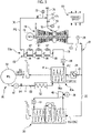
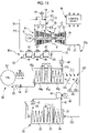
- the gas turbine plant of this embodiment includes a gas turbine 10, a generator 19 that generates electricity by the drive of the gas turbine 10, an exhaust gas line 20, a heat recovery steam generator 30, a steam turbine 40, a generator 49 that generates electricity by the drive of the steam turbine 40, a condenser 41, decomposition gas supply equipment 50 that decomposes ammonia to supply decomposition gas PG including hydrogen gas and nitrogen gas to the gas turbine 10, and a control device 99 that controls these components.
- the gas turbine 10 includes an air compressor 11 that compresses air A, a combustor 14 that combusts fuel in the air compressed by the air compressor 11 to generate combustion gas, and a turbine 15 that is driven by the combustion gas having high temperature and high pressure.
- the air compressor 11 includes a compressor rotor 12 that is rotated about an axis Ar and a compressor casing 13 that covers the compressor rotor 12.
- the turbine 15 includes a turbine rotor 16 that is rotated about the axis Ar and a turbine casing 17 that covers the turbine rotor 16.
- the compressor rotor 12 and the turbine rotor 16 are positioned on the same axis Ar, are connected to each other, and form a gas turbine rotor.
- a rotor of the generator 19 is connected to the gas turbine rotor.
- the gas turbine 10 further includes an intermediate casing 18 that is positioned between the compressor casing 13 and the turbine casing 17 and connects the compressor casing 13 to the turbine casing 17.
- the combustor 14 is mounted on the intermediate casing 18.
- the compressor casing 13, the intermediate casing 18, and the turbine casing 17 are connected to each other, and form a gas turbine casing.
- a fuel line 75 is connected to the combustor 14.
- the fuel line 75 is provided with a fuel flow meter 76 that measures the flow rate of fuel flowing through the fuel line 75 and a fuel control valve 77 that controls the flow rate of fuel flowing through the fuel line 75.
- a natural gas line 79 through which natural gas NG as a part of fuel flows is connected to the fuel line 75.
- Exhaust gas EG which is exhausted from the gas turbine 10 flows through the exhaust gas line 20.
- the exhaust gas line 20 includes a main exhaust gas line 21, a first exhaust gas line 22, and a second exhaust gas line 23.
- a first end of the main exhaust gas line 21 is connected to an exhaust port of the turbine 15.
- the first exhaust gas line 22 and the second exhaust gas line 23 are connected to a second end of the main exhaust gas line 21. That is, the exhaust gas line 20 branches into the first exhaust gas line 22 and the second exhaust gas line 23 at the second end of the main exhaust gas line 21.
- the heat recovery steam generator 30 includes an outer boiler frame 31 through which the exhaust gas EG flows, an economizer 32, an evaporator 33, and a superheater 34.
- the outer boiler frame 31 is connected to the first exhaust gas line 22. Accordingly, first exhaust gas EG1 having flowed through the first exhaust gas line 22 flows into the outer boiler frame 31. For this reason, it can also be said that the outer boiler frame 31 forms a part of the first exhaust gas line 22.
- the economizer 32 is disposed in the outer boiler frame 31, and exchanges heat between water and the exhaust gas EG to heat the water.
- a part of the evaporator 33 is disposed in the outer boiler frame 31, and the evaporator 33 exchanges heat between the water which has been heated by the economizer 32 and the exhaust gas EG to heat the water and convert the water into steam.
- the superheater 34 is disposed in the outer boiler frame 31, and exchanges heat between the steam and the exhaust gas EG to superheat the steam.
- the steam turbine 40 is driven by the steam that is generated by the heat recovery steam generator 30.
- a steam inlet of the steam turbine 40 and the superheater 34 of the heat recovery steam generator 30 are connected to each other through a steam line 42.
- the generator 49 is connected to the steam turbine 40.
- the condenser 41 is connected to a steam exhaust port of the steam turbine 40.
- the condenser 41 converts the steam which has been exhausted from the steam turbine 40 back into water.
- the water which has been generated by the condenser 41 is returned to the heat recovery steam generator 30.
- the condenser 41 and the economizer 32 of the heat recovery steam generator 30 are connected to each other through a water supply line 43.
- the decomposition gas supply equipment 50 includes an ammonia line 51, a heat exchanger 60 as a heating device, a decomposition gas line 70, a cooler 80, a decomposition gas compressor 85, the main exhaust gas line 21, the second exhaust gas line 23, a switcher 24, and a thermometer 25.
- Liquid ammonia which is supplied from an ammonia supply source 90 flows through the ammonia line 51, and the ammonia line 51 sends the liquid ammonia to the heat exchanger 60.
- the ammonia supply source 90 includes an ammonia tank 92 in which the liquid ammonia is stored, an ammonia pump 93 that pumps the liquid ammonia stored in the ammonia tank 92 to the decomposition gas supply equipment 50, and an ammonia shut-off valve 94 that is provided on the discharge side of the ammonia pump 93.
- the heat exchanger 60 as a heating device exchanges heat between the ammonia and the exhaust gas EG to decompose the ammonia into decomposition gas PG including hydrogen gas and nitrogen gas with the heat of the exhaust gas EG.
- the heat exchanger 60 includes a heat exchanger frame 61 through which the exhaust gas EG flows, a preheater 64, an evaporator 65, and a reactor 66.
- the heat exchanger frame 61 is connected to the second exhaust gas line 23. Accordingly, second exhaust gas EG2 having flowed through the second exhaust gas line 23 flows into the heat exchanger frame 61. For this reason, it can also be said that the heat exchanger frame 61 forms a part of the second exhaust gas line 23.
- the preheater 64 is connected to the ammonia line 51.
- the preheater 64 is disposed in the heat exchanger frame 61, and exchanges heat between the liquid ammonia which has been sent from the ammonia line 51 and the exhaust gas EG to heat the liquid ammonia.
- a part of the evaporator 65 is disposed in the heat exchanger frame 61, and the evaporator 65 exchanges heat between the liquid ammonia which has been heated by the preheater 64 and the exhaust gas EG to further heat the liquid ammonia and vaporize the liquid ammonia into ammonia gas.
- the reactor 66 is disposed in the heat exchanger frame 61, exchanges heat between the ammonia gas and the exhaust gas EG, and decomposes the ammonia gas into decomposition gas PG including hydrogen gas and nitrogen gas with the heat of the exhaust gas EG.
- the heat exchanger frame 61 is provided with an exhaust gas inlet 62 and an exhaust gas outlet 63.
- the preheater 64, the evaporator 65, and the reactor 66 are arranged in the heat exchanger frame 61 in this order toward the exhaust gas inlet 62 from the exhaust gas outlet 63.
- the reactor 66 includes a flow channel-forming member 67 that forms a flow channel through which ammonia gas and the decomposition gas PG flow in the heat exchanger frame 61 through which the exhaust gas EG flows, and a catalyst 68 that is provided in the flow channel formed by the flow channel-forming member 67.
- the flow channel-forming member 67 is formed of, for example, a heat transfer pipe or a combination of a plurality of plates.
- Co-CeZrOx, 4wt%Cs/Co-CeZrOx, 1wt%K/Co-CeZrOx, 10wt%Ba/Co-CeZrOx, Cs 2 O/Ru/Mg-Al, and the like are used as the catalyst 68.
- Each of these catalysts is a catalyst of which the conversion ratio of the conversion of ammonia gas into hydrogen gas and nitrogen gas is high at a temperature of 450°C to 700°C.
- a first end of the decomposition gas line 70 is connected to the reactor 66.
- a second end of the decomposition gas line 70 is connected to the fuel line 75. Accordingly, natural gas NG that has flowed into the fuel line 75 from the natural gas line 79 and the decomposition gas PG that has flowed into the fuel line 75 from the decomposition gas line 70 can be supplied to the combustor 14 as fuel.
- the cooler 80 is provided on the decomposition gas line 70.
- the cooler 80 is, for example, a heat exchanger and exchanges heat between a refrigerant and the decomposition gas PG to cool the decomposition gas PG.
- the decomposition gas compressor 85 is provided on the decomposition gas line 70 at a position closer to the combustor than the cooler 80 is.
- the decomposition gas compressor 85 increases the pressure of the decomposition gas PG which has been cooled by the cooler 80, to a feed pressure at which the decomposition gas PG is allowed to be fed to the combustor 14.
- the decomposition gas compressor 85 of this embodiment includes a plurality of partial boosters 86 that are connected in series and sequentially increase the pressure of the decomposition gas PG. Rotors of the plurality of partial boosters 86 are connected to each other and are integrally rotated as the rotor of the decomposition gas compressor.
- a boost cooler 87 is provided between two partial boosters 86 which are adjacent to each other among the plurality of partial boosters 86.
- the boost cooler 87 functions to increase boost efficiency at the downstream partial booster 86 of the two partial boosters 86 adjacent to each other, by cooling the decomposition gas PG of which the pressure has been increased by the upstream partial booster 86 and reducing the volume of the decomposition gas PG.
- the boost coolers 87 also function to suppress the recombination of hydrogen gas and nitrogen gas included in the decomposition gas PG by suppressing the temperature rise of the decomposition gas PG.
- the boost coolers 87 are not essential and may be omitted.
- the rotors of the plurality of partial boosters 86 of this embodiment are connected to each other, but the respective rotors of the plurality of partial boosters 86 may be independent of each other.
- the decomposition gas compressor 85 of this embodiment includes the plurality of partial boosters 86, but the decomposition gas compressor 85 may be formed of only one booster as long as the decomposition gas compressor 85 can increase the pressure of the decomposition gas PG to a pressure equal to or higher than the feed pressure.
- a decomposition gas flow meter 73 that measures the flow rate of the decomposition gas PG flowing through the decomposition gas line 70 and a decomposition gas control valve 72 that adjusts the flow rate of the decomposition gas PG flowing through the decomposition gas line 70 are further provided on the decomposition gas line 70 at positions closer to the combustor than the decomposition gas compressor 85 is.
- the feed pressure which is the pressure of the decomposition gas PG at which the decomposition gas PG is allowed to be fed to the combustor 14, is, for example, 5 MPa.
- the decomposition gas compressor 85 receives decomposition gas PG of which the pressure is lower than 5 MPa as the feed pressure, and increases the pressure of the decomposition gas PG to 5 MPa or more.
- the ammonia pump 93 increases the pressure of the liquid ammonia which has been sent from the ammonia tank 92, and sends this liquid ammonia to the heat exchanger 60. It is preferable to increase the pressure of liquid ammonia to at least 0.3 MPa or more by the ammonia pump 93 to send ammonia to the heat exchanger 60.
- the discharge pressure of the ammonia pump 93 is 0.3 MPa or more and lower than the feed pressure (for example, 5 MPa).
- the discharge pressure of the ammonia pump 93 is, for example, 1 MPa.
- the pressure of ammonia present in the heat exchanger 60 is 0.3 MPa or more and lower than the feed pressure (for example, 5 MPa), and is, for example, 1 MPa.
- the pressure of ammonia present in the heat exchanger 60 that is, the pressure of ammonia received by the heat exchanger 60 is 0.3 MPa or more in this embodiment, but is more preferably 1 MPa or more.
- the switcher 24 is provided on the second exhaust gas line 23.
- the switcher 24 changes the flow of the exhaust gas EG between a first state where the exhaust gas EG (first exhaust gas EG1) flows through only the first exhaust gas line 22 and a second state where the exhaust gas EG (second exhaust gas EG2) flows through at least the second exhaust gas line 23.
- the exhaust gas EG flows not only through the second exhaust gas line 23 but also through the first exhaust gas line 22.
- the switcher 24 includes a damper valve that is provided on the second exhaust gas line 23 and a valve actuator that drives the damper valve.
- the switcher 24 may be provided at the position of the second end of the main exhaust gas line 21, that is, at a position where the first exhaust gas line 22 and the second exhaust gas line 23 branch from the main exhaust gas line 21.
- the thermometer 25 is provided on the main exhaust gas line 21, and measures the temperature of the exhaust gas EG that flows through the main exhaust gas line 21.
- the control device 99 controls the switcher 24, the fuel control valve 77, the decomposition gas control valve 72, and the like according to various commands that are input from the outside, or the temperature that is measured by the thermometer 25 provided on the main exhaust gas line 21, the flow rate that is measured by the fuel flow meter 76 provided on the fuel line 75, the flow rate that is measured by the decomposition gas flow meter 73 provided on the decomposition gas line 70, and the like.
- an adjuster 71 for adjusting a ratio of the flow rate of the decomposition gas PG to the flow rate of all fuel gas which includes the natural gas NG and the decomposition gas PG supplied to the gas turbine 10, includes the fuel control valve 77 and the decomposition gas control valve 72.
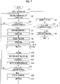
- the decomposition gas control valve 72 and the ammonia shut-off valve 94 are in a closed state. Further, the switcher 24 is in the first state where the exhaust gas EG (first exhaust gas EG1) flows through only the first exhaust gas line 22. At the time of start of the gas turbine 10, only the natural gas NG of fuel of the gas turbine 10 is supplied to the combustor 14. For this purpose, the decomposition gas control valve 72 is closed as described above at the time of start of the gas turbine 10. In a case where the gas turbine 10 is to be started, first, the control device 99 obtains the calorific value of fuel at which an output corresponding to a load represented by a load command input from the outside can be obtained.
- the control device 99 determines the opening degree of the fuel control valve 77 corresponding to the flow rate of the natural gas NG at which the calorific value of fuel can be met, and instructs the fuel control valve 77 of this opening degree.
- the natural gas NG is supplied to the combustor 14 of the gas turbine 10 through the natural gas line 79 and the fuel line 75 (S1: natural gas supply step).
- fuel is combusted in the compressed air and combustion gas having high temperature and high pressure is generated.
- the combustion gas is sent into the turbine casing 17, and rotates the turbine rotor 16.
- the generator 19 connected to the gas turbine 10 generates electricity.
- the combustion gas which has rotated the turbine rotor 16 is exhausted from the gas turbine 10 as the exhaust gas EG and flows into the heat recovery steam generator 30 through the main exhaust gas line 21 and the first exhaust gas line 22.
- the heat recovery steam generator 30 converts water into steam with the heat of the exhaust gas EG while the exhaust gas EG passes through the heat recovery steam generator 30 (S2: steam generation step). Specifically, heat is exchanged between water and the exhaust gas EG in the economizer 32 of the heat recovery steam generator 30, so that this water is heated. This water is further heated by the exhaust gas EG in the evaporator 33 of the heat recovery steam generator 30, and is converted into steam.
- This steam is further superheated by the exhaust gas EG in the superheater 34 of the heat recovery steam generator 30, and is converted into superheated steam.
- This superheated steam is sent to the steam turbine 40 through the steam line 42, and drives the steam turbine 40.
- the generator 49 connected to the steam turbine 40 generates electricity.
- Steam exhausted from the steam turbine 40 is cooled by the condenser 41, and is converted into water. This water is returned to the economizer 32 of the heat recovery steam generator 30 through the water supply line 43.
- the control device 99 determines whether or not a stop condition of the gas turbine 10 is satisfied (S3: GT stop condition determination step).
- the stop condition of the gas turbine 10 includes, for example, that a load represented by a load command input from the outside is 0, that an emergency stop command or the like is received from the gas turbine 10, and the like. If the control device 99 determines that the stop condition is not satisfied, the control device 99 repeats the determination of whether or not the stop condition is satisfied until the stop condition is satisfied. Meanwhile, fuel is supplied to the gas turbine 10 and the heat recovery steam generator 30 continues to generate steam. If the control device 99 determines that the stop condition is satisfied, the control device 99 stops the supply of fuel to the combustor 14 (S4: fuel supply stopping step). In the fuel supply stopping step (S4), the control device 99 outputs an instruction to the fuel control valve 77 to be closed. As a result, the fuel control valve 77 reaches a closed state, and the supply of fuel to the combustor 14 is stopped.
- thermometer 25 measures the temperature of the exhaust gas EG that flows through the main exhaust gas line 21 (S5: exhaust gas temperature measurement step).
- the control device 99 determines whether or not a supply condition of the decomposition gas PG is satisfied (S6: PG supply condition determination step).
- the supply condition of the decomposition gas PG includes that the ammonia supply source 90 is in a state of being able to supply ammonia to the decomposition gas supply equipment 50, that the temperature of the exhaust gas EG is equal to or higher than a predetermined temperature, and the like.
- the state of the ammonia supply source 90 being able to supply ammonia to the decomposition gas supply equipment 50 is, for example, a state where the amount of ammonia stored in the ammonia tank 92 is equal to or larger than a predetermined amount.
- the control device 99 receives a state signal output from a control device for the ammonia supply source 90 as to whether or not the ammonia supply source 90 is in the state of being able to supply ammonia, and makes the determination according to the contents represented by the state signal. Further, the control device 99 determines whether or not the temperature of the exhaust gas EG is equal to or higher than a predetermined temperature on the basis of the temperature that is measured by the thermometer 25.
- the flow rate of the natural gas NG supplied to the combustor 14 gradually increases while the gas turbine 10 is started. For this reason, the flow rate of the exhaust gas EG exhausted from the gas turbine 10 gradually increases and the temperature of the exhaust gas EG gradually rises.
- the temperature of the exhaust gas EG is, for example, 650°C or more in this embodiment.
- the temperature of 650°C which is the lowest temperature of the exhaust gas EG exhausted from the gas turbine 10 having reached the steady operating state is used as the predetermined temperature in this embodiment. This temperature is a temperature that is higher than a temperature at which ammonia can be thermally decomposed in the heat exchanger 60.
- the control device 99 determines that the supply condition of the decomposition gas PG is satisfied.
- the control device 99 determines that the supply condition of the decomposition gas PG is satisfied, the control device 99 instructs the switcher 24 to be in the second state.
- the switcher 24 is switched to the second state from the first state, and the exhaust gas EG exhausted from the gas turbine 10 branches so that the exhaust gas EG (second exhaust gas EG2) flows through the second exhaust gas line 23 while a state where the exhaust gas EG (first exhaust gas EG1) flows through the first exhaust gas line 22 is maintained (S7: switching/branching step).
- the control device 99 instructs the ammonia supply source 90 to supply ammonia.
- control device 99 instructs the ammonia shut-off valve 94 to be opened and instructs the ammonia pump 93 to be driven.
- These instructions are sent to the ammonia pump 93 and the ammonia shut-off valve 94 from the control device 99 of the gas turbine plant through the control device for the ammonia supply source 90.
- ammonia supplied from the ammonia supply source 90 starts to be supplied to the heat exchanger 60 (S8: ammonia supply step).
- the ammonia After ammonia is supplied to the heat exchanger 60, the ammonia starts to be heated by heat exchange between the ammonia and the exhaust gas EG having a temperature of 650°C or more (S11: heating step (heat exchange step)).
- the heating step (S11) first, the preheater 64 exchanges heat between liquid ammonia which has been supplied from the ammonia supply source 90 and the exhaust gas EG to heat the liquid ammonia (S12: preheating step).
- the temperature of the liquid ammonia which has been supplied from the ammonia supply source 90 is 15°C and the pressure of the liquid ammonia is 1 MPa.
- the liquid ammonia having a pressure of 1 MPa evaporates at a temperature of 25°C.
- the liquid ammonia having a temperature of 15°C is heated and converted into liquid ammonia having a temperature of about 25°C.
- the evaporator 65 exchanges heat between the liquid ammonia having a temperature of about 25°C and the exhaust gas EG to heat and vaporize the liquid ammonia and convert the liquid ammonia into ammonia gas having a temperature of 25°C (S13: evaporation step).
- the reactor 66 exchanges heat between the ammonia gas having a temperature of 25°C and the exhaust gas EG to heat and thermally decompose the ammonia gas, decompose the ammonia gas into hydrogen gas and nitrogen gas, and convert the ammonia gas into decomposition gas PG having a temperature of about 600°C (S14: reaction step).
- the reaction step (S14) the thermal decomposition of the ammonia gas is facilitated by the catalyst 68 provided in the reactor 66.
- ammonia gas it is preferable for the decomposition of ammonia gas that ammonia be heated up to a high temperature under low pressure.
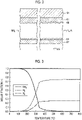
- the molar fractions of ammonia gas, hydrogen gas, and nitrogen gas which are obtained under an environment where (cesium oxide+ruthenium) catalyst (for example, Cs 2 O/Ru/Mg-Al having been described above) is used as the catalyst 68 at a pressure of 1 MPa, are shown in Fig. 3 .
- the temperature exceeds about 100°C the ammonia gas starts to decompose and the molar fraction of the ammonia gas gradually reduces.
- the molar fractions of the hydrogen gas and the nitrogen gas gradually increase conversely. Accordingly, it is necessary to heat the ammonia gas to a temperature higher than 100°C to increase the kinetic energy of the ammonia gas to be equal to or larger than active energy under this environment.
- the molar fraction of the ammonia gas rapidly reduces. After the temperature exceeds 400°C, the molar fraction of the ammonia gas reaches 0.05 or less. Then, after the temperature reaches 600°C, the molar fraction of the ammonia gas reaches substantially 0. Since the temperature of gas flowing out of the reactor 66 is set to 600°C in this embodiment, the molar fraction of the ammonia gas reaches substantially 0 and most of the ammonia gas becomes hydrogen gas and nitrogen gas.
- ammonia gas remains slightly in the gas flowing out of the reactor 66. Specifically, 0.49 mol% of ammonia gas remains. Accordingly, hydrogen gas, nitrogen gas, and a slight amount of ammonia gas are included in the gas flowing out of the reactor 66, that is, the decomposition gas PG.
- the heating step (S11) ends with the reaction step (S14).
- the decomposition gas PG which has a temperature of 600°C and has flowed in from the heat exchanger 60 is cooled by the cooler 80 (S15: cooling step).
- the cooling step (S15) heat is exchanged between the decomposition gas PG having a temperature of 600°C and a refrigerant and the decomposition gas PG is cooled to a temperature lower than 100°C.
- the decomposition gas PG having a temperature of 600°C is converted into decomposition gas PG having a temperature of, for example, 40°C by the cooler 80. Since the decomposition gas PG is cooled to a temperature lower than 100°C as described above, the generation of ammonia gas caused by the recombination of hydrogen gas and nitrogen gas included in the decomposition gas PG can be suppressed.
- the decomposition gas PG which has been cooled by the cooler 80 is cooled by the boost coolers 87 while the pressure of the decomposition gas PG is increased to a pressure equal to or higher than the feed pressure (for example, 5 MPa) by the plurality of partial boosters 86 of the decomposition gas compressor 85 (S16: boosting/boosting-cooling step). Since the decomposition gas PG of which the pressure is being increased is cooled by the boost coolers 87 as described above, the boost efficiency of the plurality of boosters can be improved. Accordingly, energy required to drive the plurality of partial boosters 86 can be reduced. In addition, since the temperature rise of the decomposition gas PG is suppressed, the recombination of hydrogen gas and nitrogen gas included in the decomposition gas PG can be suppressed.
- the decomposition gas PG flows into the fuel line 75.
- the natural gas NG which has been supplied from the natural gas line 79 also flows into the fuel line 75.
- the flow rate of the decomposition gas PG and the natural gas NG which have flowed into the fuel line 75 is adjusted by the fuel control valve 77. Accordingly, the ratio of the flow rate of the decomposition gas PG to the flow rate of all fuel gas which includes the natural gas NG and the decomposition gas PG is adjusted by the adjuster 71 that includes the decomposition gas control valve 72 and the fuel control valve 77 (S17: flow ratio adjustment step).
- a predetermined value relating to the ratio of the flow rate of the decomposition gas PG to the flow rate of all fuel gas is stored in the control device 99.
- the predetermined value is a value determined so that, for example, NOx concentration in the exhaust gas EG is less than an environmental standard. NOx concentration in the exhaust gas EG exhausted from the gas turbine 10 increases with an increase in the amount of residual ammonia gas included in the decomposition gas PG. As described above, the decomposition of ammonia gas is suppressed and the amount of the residual ammonia gas increases as pressure under a decomposition reaction environment increases. For this reason, the above-mentioned predetermined value is reduced to reduce the NOx concentration in the exhaust gas EG as pressure under a decomposition reaction environment, that is, pressure in the heat exchanger 60 increases.
- the control device 99 obtains the calorific value of fuel at which an output corresponding to a load represented by a load command can be obtained.
- the control device 99 obtains the flow rate of all fuel gas and the flow rate of the decomposition gas which are to be obtained when the above-mentioned ratio of the flow rate is set to the predetermined value, on the basis of this calorific value of fuel.
- the control device 99 determines the opening degree of the decomposition gas control valve 72 corresponding to the flow rate of the decomposition gas, and instructs the decomposition gas control valve 72 of this opening degree.
- the control device 99 obtains the opening degree of the fuel control valve 77 corresponding to the flow rate of all fuel gas, and instructs the fuel control valve 77 of this opening degree.
- the decomposition gas PG and the natural gas NG which have flowed into the fuel line 75 are supplied to the combustor 14 after passing through the fuel control valve 77 (S18: decomposition gas supply step).
- the decomposition gas PG and the natural gas NG as fuel are combusted in the air that has been compressed by the air compressor 11.
- combustion gas having high temperature and high pressure is generated.
- This combustion gas is sent into the turbine casing 17, and is exhausted from the gas turbine 10 after rotating the turbine rotor 16.
- a part of the exhaust gas EG which has been exhausted from the gas turbine 10 is used to heat water in the heat recovery steam generator 30 as the first exhaust gas EG1.
- the second exhaust gas EG2 which is the rest of the exhaust gas EG is used to heat ammonia in the heat exchanger 60.
- the control device 99 determines whether or not the supply condition of the decomposition gas PG is satisfied (S19: PG supply condition determination step). If the supply condition of the decomposition gas PG is satisfied, the steps from the heating step (S11) to the PG supply condition determination step (S19) having been described above are repeatedly performed. On the other hand, if the control device 99 determines that the supply condition of the decomposition gas PG is not satisfied in the PG supply condition determination step (S19), the control device 99 instructs the ammonia supply source 90 to stop supplying ammonia.
- control device 99 instructs the ammonia pump 93 to stop and instructs the ammonia shut-off valve 94 to be closed. As a result, the supply of ammonia to the heat exchanger 60 from the ammonia supply source 90 is stopped (S20: ammonia supply stopping step).
- the control device 99 instructs the ammonia supply source 90 to stop supplying ammonia
- the control device 99 instructs the switcher 24 to return to the first state from the second state (S21: switching step).
- the exhaust gas EG exhausted from the gas turbine 10 does not flow through the second exhaust gas line 23 and flows through only the first exhaust gas line 22.
- the first exhaust gas EG1 is supplied to the heat recovery steam generator 30 from the first exhaust gas line 22 even after the supply condition of the decomposition gas PG is no longer satisfied, and steam continues to be generated by the heat recovery steam generator 30.
- processing After the switching step (S21) is performed, processing returns to the temperature measurement step (S5) again. Then, if the temperature measured in the temperature measurement step (S5) satisfies the supply condition of the decomposition gas PG, the supply of ammonia from the ammonia supply source 90 is started (S8) and the supply of the decomposition gas PG to the combustor 14 is started (S18) as described above.
- control device 99 determines that the stop condition of the gas turbine 10 is satisfied (S3), the control device 99 outputs an instruction to the fuel control valve 77 to be closed, and stops the supply of fuel to the combustor 14 (S4) as described above. Since the flow rate of fuel supplied to the combustor 14 gradually reduces in the fuel supply stopping step (S4), the temperature of the exhaust gas EG gradually lowers. For this reason, before the flow rate of fuel supplied to the combustor 14 reaches 0, the supply condition of the decomposition gas PG stops to be satisfied and the supply of ammonia from the ammonia supply source 90 is stopped (S20).
- low-pressure ammonia having a pressure lower than the feed pressure is received and is thermally decomposed by the heat exchanger 60, and the pressure of decomposition gas PG generated through the thermal decomposition is then increased up to a pressure equal to or higher than the feed pressure by the decomposition gas compressor 85. For this reason, the thermal decomposition of ammonia in the heat exchanger 60 is facilitated, so that the amount of the residual ammonia gas included in the decomposition gas PG can be reduced.
- the decomposition gas PG flowing out of the heat exchanger 60 is immediately cooled by the cooler 80 not including a catalyst, the generation of ammonia gas caused by the recombination of hydrogen gas and nitrogen gas included in the decomposition gas PG can be suppressed. Accordingly, the amount of NOx included in the combustion gas generated through the combustion of the decomposition gas PG can be reduced in this embodiment.
- the ratio of the flow rate of the decomposition gas PG to the flow rate of all fuel can be increased.
- the gas turbine plant of this embodiment is a plant where the decomposition gas supply equipment 50 is added to a general gas turbine plant including the gas turbine 10 and the heat recovery steam generator 30. For this reason, in this embodiment, an existing general gas turbine plant can be easily modified into the gas turbine plant. Further, even in a case where the temperature of the exhaust gas EG does not reach a temperature required for the decomposition of ammonia at the time of start of the gas turbine 10, or the like, the heat of the exhaust gas EG can be effectively used in the heat recovery steam generator 30 in the gas turbine plant of this embodiment.
- the exhaust gas EG starts to flow into the heat exchanger 60 (S7) and ammonia starts to be supplied to the heat exchanger 60 from the ammonia supply source 90 (S8) in this embodiment.
- ammonia is heated up to a high temperature from the start of the supply of ammonia to the heat exchanger 60 from the ammonia supply source 90 in this embodiment, so that decomposition gas PG including a small amount of residual ammonia gas can be generated.
- the amount of NOx included in the combustion gas generated through the combustion of the decomposition gas PG can be reduced from the start of the supply of ammonia to the heat exchanger 60 from the ammonia supply source 90.
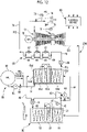
- the gas turbine plant of this embodiment includes a pressure reducer 52 and a preheater 53 instead of the preheater 64 and the evaporator 65 of the gas turbine plant of the first embodiment.
- Both the pressure reducer 52 and the preheater 53 are components of decomposition gas supply equipment 50a of this embodiment.
- the pressure reducer 52 is provided on the ammonia line 51 that extends from the ammonia supply source 90.
- the pressure reducer 52 reduces the pressure of liquid ammonia which flows through the ammonia line 51 to a pressure lower than 0.3 MPa.
- Liquid ammonia having a pressure of 0.3 MPa is vaporized at a temperature of about 0°C and is converted into ammonia gas. For this reason, when an environment where the pressure reducer 52 is disposed is higher than 0°C, the liquid ammonia can be vaporized and converted into ammonia gas while passing through the pressure reducer 52, before the liquid ammonia is heated by a heat exchanger 60a.
- the discharge pressure of the ammonia pump 93 of this embodiment is, for example, 1 MPa as exemplified in the first embodiment.
- the pressure reducer 52 of this embodiment reduces the pressure of the liquid ammonia which has been sent from the ammonia pump 93, to, for example, 0.1 MPa, that is, about atmospheric pressure.
- Liquid ammonia having a pressure of 0.1 MPa is vaporized at a temperature of about -30°C and is converted into ammonia gas.
- the pressure reducer 52 is disposed under an environment higher than -30°C. For this reason, the liquid ammonia can be almost reliably vaporized and converted into ammonia gas while passing through the pressure reducer 52, before the liquid ammonia is heated by the heat exchanger 60a.
- the preheater 53 is provided on the ammonia line 51 at a position closer to the heat exchanger 60a than the pressure reducer 52 is.
- the preheater 53 uses river water, seawater, atmospheric air, or the like as an external medium, and exchanges heat between the external medium and ammonia to heat the ammonia. While the ammonia passes through the preheater 53, the ammonia is heated up to a temperature in the range of about 15°C to 25°C, depending on the temperature of the external medium, and the like.
- the pressure of liquid ammonia is reduced to about 0.3 MPa (here, a pressure lower than 0.3 MPa) by the pressure reducer 52, the liquid ammonia can be almost reliably converted into ammonia gas while passing through the preheater 53.
- the heat exchanger 60a of this embodiment includes a reactor 66a and a heat exchanger frame 61a and does not include the preheater 64 and the evaporator 65 of the heat exchanger 60 of the first embodiment.
- the reactor 66a includes a catalyst that facilitates the thermal decomposition of ammonia gas as with the reactor 66 of the first embodiment.
- the reactor 66a heats and thermally decomposes ammonia gas which has a temperature in the range of about 15°C to 25°C, with the heat of the exhaust gas EG, decomposes the ammonia gas into hydrogen gas and nitrogen gas, and converts the ammonia gas into decomposition gas PG having a temperature of about 600°C as in the first embodiment.
- the heat exchanger 60a of this embodiment does not include the preheater 64 and the evaporator 65 and includes only the reactor 66a.
- the heat exchanger 60 of the first embodiment includes the preheater 64, the evaporator 65, and the reactor 66.
- the temperature of ammonia flowing into the heat exchanger 60a of this embodiment and the temperature of ammonia flowing into the heat exchanger 60 of the first embodiment are substantially equal to each other.
- the temperature of decomposition gas PG flowing out of the heat exchanger 60a of this embodiment and the temperature of decomposition gas PG flowing out of the heat exchanger 60 of the first embodiment are equal to each other. For this reason, the heat-transfer area of the heat exchanger 60a of this embodiment and the heat-transfer area of the heat exchanger 60 of the first embodiment are substantially equal to each other.
- the decomposition gas PG flowing out of the heat exchanger 60a is guided to the combustor 14 through the decomposition gas line 70 and the fuel line 75 as in the first embodiment.
- the decomposition gas PG is cooled by the cooler 80 while passing through the decomposition gas line 70 as in the first embodiment.
- the pressure of the decomposition gas PG is increased to a pressure equal to or higher than the feed pressure (for example, 5 MPa) by the decomposition gas compressor 85.
- the decomposition gas PG is supplied to the combustor 14.
- the molar fractions of ammonia gas, hydrogen gas, and nitrogen gas which are obtained under an environment where (cesium oxide+ruthenium) catalyst (for example, Cs 2 O/Ru/Mg-Al having been described above) is used as the catalyst at a pressure of 0.1 MPa, are shown in Fig. 6 .
- the temperature exceeds about 100°C the ammonia gas starts to decompose and the molar fraction of the ammonia gas gradually reduces as in the case of 1 MPa.
- the molar fractions of the hydrogen gas and the nitrogen gas gradually increase conversely.
- the temperature exceeds about 200°C the molar fraction of the ammonia gas rapidly reduces.
- the molar fraction of the ammonia gas After the temperature exceeds 350°C, the molar fraction of the ammonia gas reaches 0.01 or less. Then, after the temperature reaches 600°C, the molar fraction of the ammonia gas reaches substantially 0. Since the temperature of gas flowing out of the reactor 66a is set to 600°C also in this embodiment, the molar fraction of the ammonia gas reaches substantially 0 and most of the ammonia gas becomes hydrogen gas and nitrogen gas. Here, even in a case where the temperature of gas flowing out of the reactor 66a is 600°C, ammonia gas remains very slightly in the gas flowing out of the reactor 66a. Specifically, 0.05 mol% of ammonia gas remains.
- the concentration (0.05 mol%) of residual ammonia gas included in the decomposition gas PG in this embodiment is lower than the concentration (0.49 mol%) of the residual ammonia gas included in the decomposition gas PG in the first embodiment.
- the reason for this is that the pressure of ammonia gas under a decomposition reaction environment, that is, pressure in the heat exchanger 60a is lower than that of the first embodiment.
- S1 to S8 are also performed in the gas turbine plant of this embodiment as in the gas turbine plant of the first embodiment.
- the pressure of liquid ammonia supplied from the ammonia supply source 90 is reduced by the pressure reducer 52 in this embodiment (S9: pressure reducing step).
- the ammonia of which the pressure has been reduced by the pressure reducer 52 is heated by the preheater 53 disposed outside the heat exchanger 60a (S10: preheating step).
- the preheater 53 uses river water, seawater, atmospheric air, or the like as an external medium, and exchanges heat between the external medium and ammonia to heat the ammonia up to a temperature in the range of about 15°C to 25°C. As a result, ammonia having passed through the preheater 53 is almost reliably converted into ammonia gas as described above.
- the ammonia gas generated from the preheater 53 flows into the heat exchanger 60a as a heating device, and is heated by heat exchange with the exhaust gas EG in the heat exchanger 60a (S11a: heating step (heat exchange step)).
- the reactor 66a of the heat exchanger 60a exchanges heat between the ammonia gas and the exhaust gas EG to heat and thermally decompose the ammonia gas and convert the ammonia gas into decomposition gas PG (S14a: reaction step).
- the decomposition gas PG flowing out of the heat exchanger 60a is subjected to the cooling step (S15) performed in the cooler 80, an increase in pressure performed in the decomposition gas compressor 85, the boosting-cooling step (S16) performed by the boost coolers 87, and the adjustment step (S17) performed in the adjuster 71, and is supplied to the combustor 14 (S18).
- the concentration of the residual gas ammonia included in the decomposition gas PG generated through the thermal decomposition of gas ammonia in the heat exchanger 60a in this embodiment is even lower than that in the first embodiment.
- a predetermined value relating to the ratio of the flow rate of the decomposition gas PG to the flow rate of all fuel gas in the adjustment step (S17) of this embodiment, that is, the ratio stored in the control device 99 is larger than that of the first embodiment. Accordingly, the amount of the decomposition gas PG supplied to the combustor 14 in this embodiment is larger than that in the first embodiment.
- the control device 99 determines whether or not the supply condition of the decomposition gas PG is satisfied (S19: PG supply condition determination step). If the supply condition of the decomposition gas PG is satisfied, the steps from the pressure reducing step (S9) to the PG supply condition determination step (S19) are repeatedly performed. On the other hand, if the control device 99 determines that the supply condition of the decomposition gas PG is not satisfied in the PG supply condition determination step (S19), the control device 99 instructs the ammonia supply source 90 to stop supplying ammonia as in the first embodiment. As a result, the supply of ammonia to the heat exchanger 60a from the ammonia supply source 90 is stopped (S20: ammonia supply stopping step).
- the control device 99 instructs the ammonia supply source 90 to stop supplying ammonia
- the control device 99 instructs the switcher 24 to return to the first state from the second state as in the first embodiment (S21: switching step).
- the exhaust gas EG exhausted from the gas turbine 10 does not flow through the second exhaust gas line 23 and flows through only the first exhaust gas line 22. Then, processing returns to the temperature measurement step (S5).
- low-pressure ammonia having a pressure lower than the feed pressure is received and is thermally decomposed by the heat exchanger 60a, and the pressure of decomposition gas PG generated through the thermal decomposition is then increased up to a pressure equal to or higher than the feed pressure by the decomposition gas compressor 85.
- the amount of NOx included in the combustion gas generated through the combustion of the decomposition gas PG can be reduced also in this embodiment, and the ratio of the flow rate of the decomposition gas PG to the flow rate of all fuel can be increased.
- the molar fraction of the residual ammonia gas can be reduced to lower than 0.1 if the low-pressure ammonia is heated up to a temperature of 500°C or more by the heat exchangers 60 and 60a. For this reason, it is preferable that the low-pressure ammonia be heated up to a temperature of 500°C or more in the heat exchangers 60 and 60a, and it is more preferable that the low-pressure ammonia be heated up to a temperature of 600°C or more in the heat exchangers 60 and 60a.
- the molar fraction of the residual ammonia gas at the feed pressure (for example, 5 MPa) is shown in Fig. 9 to be used to describe a third embodiment.
- an existing general gas turbine plant can be easily changed into the gas turbine plant of this embodiment for the same reason as the reason described in the first embodiment.
- the amount of NOx included in the combustion gas generated through the combustion of the decomposition gas PG can be reduced from the start of the supply of ammonia to the heat exchanger 60a from the ammonia supply source 90.
- the concentration of the residual gas ammonia included in the decomposition gas PG generated through the thermal decomposition of gas ammonia in the heat exchanger 60a in this embodiment can be reduced to even lower than that in the first embodiment.
- the amount of NOx included in the combustion gas generated through the combustion of the decomposition gas PG in this embodiment can be made smaller than that in the first embodiment, and the ratio of the flow rate of the decomposition gas PG to the flow rate of all fuel can be increased.
- this embodiment has advantages in that the concentration of residual gas ammonia included in the decomposition gas PG can be reduced, and that the ratio of the flow rate of the decomposition gas PG to the flow rate of all fuel can be increased, as compared to the first embodiment.
- this embodiment is more disadvantageous than the first embodiment in terms of equipment cost and power generation efficiency.
- the pressure reducer 52 is added to the gas turbine plant of the first embodiment.
- the pressure of the decomposition gas PG flowing out of the heat exchanger 60a in this embodiment is lower than that in the first embodiment, the pressure of the decomposition gas PG needs to be increased up to a pressure equal to or higher than the same feed pressure as that of the first embodiment by the decomposition gas compressor 85.
- a decomposition gas compressor 85 which has boosting capacity higher than that of the decomposition gas compressor 85 of the first embodiment is required. Accordingly, this embodiment is more disadvantageous than the first embodiment in terms of equipment cost. Further, since the decomposition gas compressor 85 of this embodiment needs to increase the pressure of gas which is lower than that of the first embodiment up to a pressure equal to or higher than the same feed pressure as that of the first embodiment, energy required to drive the decomposition gas compressor 85 is larger than that of the first embodiment. Accordingly, this embodiment is more disadvantageous than the first embodiment in terms of power generation efficiency.
- liquid ammonia which has a pressure not lower than 0.3 MPa that is the pressure required for the transport of liquid ammonia is made to flow as is into the heat exchanger 60 in the first embodiment
- the pressure reducer 52 is not necessary.
- the pressure of the decomposition gas PG flowing out of the heat exchanger 60 in the first embodiment is higher than that in the second embodiment, a decomposition gas compressor 85 which has boosting capacity lower than that of the decomposition gas compressor 85 of the second embodiment is enough. Accordingly, the first embodiment is more advantageous than the second embodiment in terms of equipment cost.
- the decomposition gas compressor 85 of the first embodiment has only to increase the pressure of gas which is higher than that of the second embodiment up to a pressure equal to or higher than the same feed pressure as that of the second embodiment, energy required to drive the decomposition gas compressor 85 is smaller than that of the second embodiment. Accordingly, the first embodiment is more advantageous than the second embodiment in terms of power generation efficiency.
- each of the first and second embodiments has advantages and disadvantages with respect to the other embodiment. For this reason, it is preferable that which of the first and second embodiments to select be determined by comparing and weighing the advantages of the second embodiment and the disadvantages of the second embodiment, that is, the advantages of the first embodiment.
- the preheater 53 disposed outside the heat exchanger 60a may be omitted and a preheater may be provided as a part of the heat exchanger 60a.
- this preheater exchanges heat between ammonia gas and the exhaust gas EG to heat the ammonia gas.
- the pressure of liquid ammonia which has been sent from the ammonia pump 93 is to be reduced to a pressure of 0.1 MPa by the pressure reducer 52, the liquid ammonia can be almost reliably converted into ammonia gas by the pressure reducer 52. Accordingly, a preheater as a part of the heat exchanger 60a is not provided and the preheater 53 disposed outside the heat exchanger 60a may be omitted.
- the flow rate of hydrogen gas supplied to the combustor 14 increases in a case where the ratio of the flow rate of the decomposition gas PG to the flow rate of all fuel is high.
- a combustor 14 suitable for the combustion of hydrogen gas be used as the combustor 14 in a case where the ratio of the flow rate of the decomposition gas PG to the flow rate of all fuel is high.
- a combustor 14 suitable for the combustion of hydrogen gas be used as the combustor 14.
- an ammonia supply source 90b of this embodiment supplies ammonia which has a pressure equal to or higher than a feed pressure (for example, 5 MPa) to a heat exchanger 60 as a heating device of the gas turbine plant of this embodiment. That is, an ammonia pump 93b of the ammonia supply source 90b of this embodiment increases the pressure of liquid ammonia which has been sent from the ammonia tank 92 to a pressure equal to or higher than the feed pressure (for example, 5 MPa), and sends the liquid ammonia to the heat exchanger 60.
- a feed pressure for example, 5 MPa
- the heat exchanger 60 of the gas turbine plant of this embodiment includes a preheater 64, an evaporator 65, and a reactor 66 as with the heat exchanger 60 of the first embodiment.
- the reactor 66 and a fuel line 75 are connected to each other through a decomposition gas line 70 as in the first embodiment.
- the decomposition gas line 70 is provided with a decomposition gas flow meter 73 and a decomposition gas control valve 72.
- the decomposition gas line 70 is not provided with the cooler 80, the decomposition gas compressor 85, and the boost coolers 87 of the first embodiment. That is, decomposition gas supply equipment 50b of this embodiment is equipment where the cooler 80, the decomposition gas compressor 85, and the boost coolers 87 are omitted from the decomposition gas supply equipment 50 of the first embodiment.
- the molar fractions of ammonia gas, hydrogen gas, and nitrogen gas which are obtained under an environment where (cesium oxide+ruthenium) catalyst (for example, Cs 2 O/Ru/Mg-Al having been described above) is used as a catalyst at a pressure of 5 MPa, are shown in Fig. 9 .
- the temperature exceeds about 100°C the ammonia gas starts to decompose and the molar fraction of the ammonia gas gradually reduces as in the cases of 1 MPa and 0.1 MPa.
- the molar fractions of the hydrogen gas and the nitrogen gas gradually increase conversely.
- the temperature exceeds about 200°C the molar fraction of the ammonia gas rapidly reduces.
- the molar fraction of the ammonia gas After the temperature exceeds 500°C, the molar fraction of the ammonia gas reaches about 0.05. At the pressure of 5 MPa, even when the temperature of the ammonia gas reaches 600°C, the molar fraction of the ammonia gas is close to 0 but does not reach substantially 0. Accordingly, in this embodiment, ammonia gas remains in the gas flowing out of the reactor 66 even in a case where the temperature of gas flowing out of the reactor 66 is 600°C. Specifically, 2.3 mol% of ammonia gas remains. The concentration (2.3 mol%) of residual ammonia gas included in the decomposition gas PG in this embodiment is higher than the concentration (0.49 mol%) of the residual ammonia gas included in the decomposition gas PG in the first embodiment. The reason for this is that the pressure of ammonia gas under a decomposition reaction environment, that is, pressure in the heat exchanger 60 is higher than that of the first embodiment.
- S1 to S8 are also performed in the gas turbine plant of this embodiment as in the gas turbine plant of the first embodiment.
- the heating step (S11) performed by the heat exchanger 60 is performed also in this embodiment as in the first embodiment.
- the preheating step (S12) performed by the preheater 64, the evaporation step (S13) performed by the evaporator 65, and the reaction step (S14) performed by the reactor 66 are performed also in the heating step (S11).
- the decomposition gas PG flowing out of the heat exchanger 60 is not subjected to the cooling step (S15) and the boosting/boosting-cooling step (S16) and is supplied to the combustor 14 (S18) after the ratio of the flow rate of the decomposition gas PG to the flow rate of all fuel gas is adjusted by the adjuster 71 (S17: adjustment step).
- the concentration of residual gas ammonia included in the decomposition gas PG generated through the thermal decomposition of gas ammonia in the heat exchanger 60 in this embodiment is higher than that in the first embodiment.
- a predetermined value relating to the ratio of the flow rate of the decomposition gas PG to the flow rate of all fuel gas in the adjustment step (S17) of this embodiment, that is, the ratio stored in the control device 99 is smaller than that of the first embodiment. Accordingly, the amount of the decomposition gas PG supplied to the combustor 14 in this embodiment is smaller than that in the first embodiment.
- the control device 99 determines whether or not the supply condition of the decomposition gas PG is satisfied (S19: PG supply condition determination step). If the supply condition of the decomposition gas PG is satisfied, the steps from the heating step (S11) to the PG supply condition determination step (S19) are repeatedly performed. On the other hand, if the control device 99 determines that the supply condition of the decomposition gas PG is not satisfied in the PG supply condition determination step (S19), the control device 99 instructs the ammonia supply source 90 to stop supplying ammonia as in the first embodiment. As a result, the supply of ammonia to the heat exchanger 60 from the ammonia supply source 90 is stopped (S20: ammonia supply stopping step).
- the control device 99 instructs the ammonia supply source 90 to stop supplying ammonia
- the control device 99 instructs the switcher 24 to return to the first state from the second state as in the first embodiment (S21: switching step).
- the exhaust gas EG exhausted from the gas turbine 10 does not flow through the second exhaust gas line 23 and flows through only the first exhaust gas line 22. Then, processing returns to the temperature measurement step (S5).
- an existing general gas turbine plant can be easily changed into the gas turbine plant of this embodiment for the same reason as the reason described in the first embodiment. Further, even in a case where the temperature of the exhaust gas EG does not reach a temperature required for the decomposition of ammonia at the time of start of the gas turbine 10, or the like, the heat of the exhaust gas EG can be effectively used in the heat recovery steam generator 30 also in the gas turbine plant of this embodiment.
- the exhaust gas EG starts to flow into the heat exchanger 60 (S7) and ammonia starts to be supplied to the heat exchanger 60 from the ammonia supply source 90 (S8) also in this embodiment.
- the amount of NOx included in the combustion gas generated through the combustion of the decomposition gas PG can be reduced from the start of the supply of ammonia to the heat exchanger 60 from the ammonia supply source 90 as in the first embodiment.
- the concentration of the residual gas ammonia included in the decomposition gas PG generated through the thermal decomposition of gas ammonia in the heat exchanger 60 in this embodiment is higher than that in the first embodiment. For this reason, the amount of NOx included in the combustion gas generated through the combustion of the decomposition gas PG is larger, and the ratio of the flow rate of the decomposition gas PG to the flow rate of all fuel is lower, in this embodiment than in in the first embodiment.
- the decomposition gas PG is used as a part of fuel of the combustion gas but the cooler 80, the decomposition gas compressor 85, and the boost coolers 87 of the first embodiment are not provided in this embodiment, equipment cost can be significantly reduced.
- the decomposition gas compressor 85 is not provided and energy required to drive the decomposition gas compressor 85 is not necessary in this embodiment, this embodiment is more advantageous than the first embodiment in terms of power generation efficiency.
- the gas turbine plant of this modification example is a plant where the heat recovery steam generator 30, the steam turbine 40, the condenser 41, the first exhaust gas line 22, and the switcher 24 are omitted from the gas turbine plant of the first embodiment. For this reason, in the gas turbine plant of this modification example, an exhaust gas line 20c does not branch and the exhaust gas line 20c is connected to the heat exchanger 60 as a heating device.
- the steam generation step (S3) of the gas turbine plant of the first embodiment is not performed in the gas turbine plant. Further, since the exhaust gas line 20c does not branch and the switcher 24 is not provided in the gas turbine plant of this modification example, the switching/branching step (S7) and the switching step (S21) of the gas turbine plant of the first embodiment are not performed in this gas turbine plant. Accordingly, if the control device 99 determines that the supply condition of the decomposition gas PG is satisfied in the PG supply condition determination step (S6), the switching/branching step (S7) is not performed and the ammonia supply step (S8) is immediately performed in this modification example.
- ammonia supplied from the ammonia supply source 90 starts to be supplied to the heat exchanger 60 after the supply condition of the decomposition gas PG is satisfied. Accordingly, the amount of NOx included in the combustion gas generated through the combustion of the decomposition gas PG can be reduced from the start of the supply of ammonia to the heat exchanger 60 from the ammonia supply source 90. Further, after the control device 99 determines that the supply condition of the decomposition gas PG is not satisfied in the PG supply condition determination step (S19) and the ammonia supply stopping step (S20) is performed, the switching step (S21) is not performed and processing immediately returns to the temperature measurement step (S5) in this modification example.
- This modification example is a modification example of the first embodiment, but the second embodiment may also be modified in the same way as this modification example. That is, the heat recovery steam generator 30, the steam turbine 40, the condenser 41, the first exhaust gas line 22, and the switcher 24 may be omitted from the gas turbine plant of the second embodiment.
- the gas turbine plant of this modification example is a plant that uses steam as an object (heat medium) to be subjected to heat exchange with ammonia in a heat exchanger 60d as a heating device.
- the heat exchanger 60d of this modification example includes a heat exchanger frame 61d through which steam flows, a preheater 64d that is disposed in the heat exchanger frame 61d, an evaporator 65d of which a part is disposed in the heat exchanger frame 61, and a reactor 66d that is disposed in the heat exchanger frame 61d.
- the heat exchanger frame 61d is provided with a steam inlet 62d and a steam outlet 63d.
- the preheater 64d, the evaporator 65d, and the reactor 66d are arranged in the heat exchanger frame 61d in this order toward the steam inlet 62d from the steam outlet 63d.
- the steam line 42 which connects the superheater 34 of the heat recovery steam generator 30 to the steam turbine 40 is provided with a thermometer 47 that measures the temperature of steam flowing through the steam line 42.
- a first end of a heat exchange steam line 44 is connected to the steam line 42.
- a second end of the heat exchange steam line 44 is connected to the steam inlet 62d of the heat exchanger frame 61d.
- the heat exchange steam line 44 is provided with a steam control valve 45 that adjusts the flow rate of steam flowing through the heat exchange steam line 44.
- a first end of a steam recovery line 46 is connected to the steam outlet 63d of the heat exchanger frame 61d.
- a second end of the steam recovery line 46 is connected to the condenser 41.
- Exhaust gas EG is not supplied to the heat exchanger 60d of this modification example. Therefore, an exhaust gas line 20d of this modification example is connected to the heat recovery steam generator 30 without branching. Accordingly, the exhaust gas line 20d of this modification example is not provided with a switcher 24.
- Exhaust gas EG is not supplied to the heat exchanger 60d of this modification example as described above. For this reason, in the temperature measurement step (S5), the temperature of steam flowing through the steam line 42 is measured by the thermometer 47 instead of the measurement of the temperature of exhaust gas EG. Further, the supply condition of the decomposition gas PG determined in the PG supply condition determination step (S6, S19) does not include a condition that the temperature of exhaust gas EG is equal to or higher than a predetermined temperature, and instead includes a condition that the temperature of steam flowing through the steam line 42 is equal to or higher than a predetermined temperature.
- a heat exchange steam supply step is performed instead of the switching/branching step (S7).
- the control device 99 instructs the steam control valve 45 to be opened.
- the steam control valve 45 is opened, and a part of steam flowing through the steam line 42 is supplied to the heat exchanger 60d through the heat exchange steam line 44.
- the ammonia supply step (S8) is performed as in the first embodiment.
- the switching step (S21) is not performed and a heat exchange steam supply stopping step is performed in this modification example.
- processing returns to the temperature measurement step (S5) after the heat exchange steam supply stopping step is performed.
- this modification example steam exhausted from the heat exchanger 60d returns to the condenser 41.
- a reheater may be provided in the heat recovery steam generator 30, and steam exhausted from the heat exchanger 60d may be sent to the reheater and may be sent to the steam line 42 after being superheated by the reheater.
- this modification example is a modification example of the first embodiment, but the second embodiment may also be modified in the same way as this modification example. That is, exhaust gas EG is not supplied to the heat exchanger of the gas turbine plant of the second embodiment, and steam generated by the heat recovery steam generator 30 may be supplied instead.
- the gas turbine plant of this modification example is a gas turbine plant in which a preheater 64, an evaporator 65, and a reactor 66 used to decompose ammonia are arranged in an outer boiler frame 31e of a heat recovery steam generator 30e.
- a heat exchanger as a heating device of this modification example includes the outer boiler frame 31e of the heat recovery steam generator 30e and the preheater 64, the evaporator 65, and the reactor 66 that are used to decompose ammonia.
- the heat exchanger 60 which is independent of the heat recovery steam generator 30 as in the first embodiment is not present in this modification example.
- an exhaust gas line 20e of this modification example is connected to the outer boiler frame 31e of the heat recovery steam generator 30e without branching.
- the switching/branching step (S7) and the switching step (S21) of the gas turbine plant of the first embodiment are not performed in this gas turbine plant as in the first modification example.
- This modification example is a modification example of the first embodiment, but the second embodiment may also be modified in the same way as this modification example. That is, the preheater 64, the evaporator 65, and the reactor 66 which are used to decompose ammonia may be arranged in the outer boiler frame 31 of the heat recovery steam generator 30 of the gas turbine plant of the second embodiment.
- the gas turbine plant of this modification example is a gas turbine plant where an incinerator 30f and a third exhaust gas line 29 guiding exhaust gas exhausted from the incinerator 30f to the main exhaust gas line 21 are added to the gas turbine plant of the first embodiment.
- wastes X and the like including combustible materials and air A are fed to the incinerator 30f.
- the wastes X and the like are combusted in the air A.
- a first end of the third exhaust gas line 29 is connected to the incinerator 30f.
- a second end of the third exhaust gas line 29 is connected to the main exhaust gas line 21.
- the thermometer 25 is provided on the main exhaust gas line 21, on the downstream side of a position where the main exhaust gas line 21 and the third exhaust gas line 29 are connected to each other.
- exhaust gas EG exhausted from the gas turbine 10 and exhaust gas exhausted from the incinerator 30f are guided to the heat exchanger 60 and the heat recovery steam generator 30.
- the heat exchanger 60 heats ammonia using at least one of the exhaust gas EG exhausted from the gas turbine 10 and the exhaust gas exhausted from the incinerator 30f as a heat medium.
- the heat recovery steam generator 30 heats water using at least one of the exhaust gas EG exhausted from the gas turbine 10 and the exhaust gas exhausted from the incinerator 30f as a heat medium.
- the heat of the exhaust gas exhausted from the incinerator 30f may be used as a heat source which heats ammonia, other than the heat of the exhaust gas EG exhausted from the gas turbine 10.
- the exhaust gas EG exhausted from the gas turbine 10 and the exhaust gas exhausted from the incinerator 30f can be introduced into the heat exchanger 60 in this modification example, but only the exhaust gas exhausted from the incinerator 30f may be introduced into the heat exchanger 60.
- this modification example is a modification example of the first embodiment, but the second and third embodiments may also be modified in the same way as this modification example.
- the gas turbine plant of this modification example is a gas turbine plant that includes a heating device 100 which includes a sunlight reflecting device 101 and a heater 60g, instead of the heat exchanger 60 as a heating device of the gas turbine plant of the first embodiment.
- the sunlight reflecting device 101 includes a reflective mirror 102 and a mirror drive unit 103 that changes the direction of the reflective mirror 102 to allow sunlight to be guided to the heater 60g.
- the heater 60g includes a preheater 64g, an evaporator 65g, and a reactor 66g. That is, solar energy is used as a heat source which heats ammonia in this modification example. For this reason, in the gas turbine plant of this modification example, an exhaust gas line 20g is connected to the heat recovery steam generator 30 without branching.
- This modification example is a modification example of the first embodiment, but the second embodiment may also be modified in the same way.
- a heat source other than the heat of the exhaust gas EG exhausted from the gas turbine 10 may be used as a heat source that heats ammonia.
- a heat source include the waste heat exhausted from a chemical process, the waste heat exhausted from a steel mill, the heat of combustion gas of biomass fuel, and the like in addition to the heat of the exhaust gas exhausted from the incinerator 30f and solar energy.
- the adjuster 71 which adjusts the flow ratio includes the fuel control valve 77 provided on the fuel line 75 and the decomposition gas control valve 72 provided on the decomposition gas line 70.
- the adjuster which adjusts the flow ratio may include a natural gas NG control valve provided on the natural gas line 79 and the decomposition gas control valve 72 provided on the decomposition gas line 70.
- each of the gas turbine plants of the first and second embodiments and the first to fifth modification examples having been described above includes the cooler 80.
- the coolers 80 may be omitted in these gas turbine plants.
- the amount of ammonia gas flowing into the combustor 14 may increase.
- NOx concentration can be reduced even though ammonia is used as at least a part of fuel.
Landscapes
- Engineering & Computer Science (AREA)
- Chemical & Material Sciences (AREA)
- Combustion & Propulsion (AREA)
- Mechanical Engineering (AREA)
- General Engineering & Computer Science (AREA)
- Engine Equipment That Uses Special Cycles (AREA)
Claims (15)
- Gasturbinenanlage, umfassend:eine Gasturbine (10), welche Brennstoff verbrennt, mithilfe des durch Verbrennung des Brennstoffs erzeugten Verbrennungsgases angetrieben wird, und das Verbrennungsgas als Abgas (EG) ausstößt;eine Heizvorrichtung (60, 60a, 60d, 60g), welche Ammoniak erwärmt und das Ammoniak thermisch zersetzt, um das Ammoniak in ein Wasserstoffgas und Stickstoffgas umfassendes Zersetzungsgas (PG) umzuwandeln; undeine Zersetzungsgasleitung (70), welche das aus der Heizvorrichtung (60, 60a, 60d, 60g) ausströmende Zersetzungsgas (PG) zur Gasturbine (10) leitet;dadurch gekennzeichnet, dass die Gasturbinenanlage weiterhin einen Zersetzungsgasverdichter (85) umfasst, welcher an der Zersetzungsgasleitung (70) bereitgestellt ist und welcher den Druck des aus der Heizvorrichtung (60, 60a, 60d, 60g) ausströmenden Zersetzungsgases (PG) auf einen Druck erhöht, der gleich hoch oder höher als der Einspeisedruck ist, bei welchem das Zersetzungsgas (PG) in die Gasturbine (10) eingespeist werden darf, wobei das Zersetzungsgas (PG), dessen Druck mithilfe des Zersetzungsgasverdichters (85) erhöht worden ist, der Gasturbine (10) als zumindest Teil des Brennstoffs zugeführt wird.
- Gasturbinenanlage gemäß Anspruch 1, weiterhin umfassend:
einen Kühler (80), welcher an einer Position der Zersetzungsgasleitung (70) bereitgestellt ist, die näher an der Heizvorrichtung (60, 60a, 60d, 60g) liegt als der Zersetzungsgasverdichter (85), und welcher das aus der Heizvorrichtung (60, 60a, 60d, 60g) ausströmende Zersetzungsgas (PG) kühlt. - Gasturbinenanlage gemäß Anspruch 1 oder 2, weiterhin umfassend:
einen Verstärkungskühler (87), welcher das Zersetzungsgas (PG) kühlt, dessen Druck mithilfe des Zersetzungsgasverdichters (85) erhöht wird. - Gasturbinenanlage gemäß einem der Ansprüche 1 bis 3, wobei die Heizvorrichtung (60, 60a, 60d, 60g) einen Reaktor (66, 66a, 66d, 66g) umfasst, welcher Ammoniakgas erwärmt und thermisch zersetzt, um das Zersetzungsgas (PG) zu erzeugen.
- Gasturbinenanlage gemäß Anspruch 4, wobei der Reaktor (66, 66a, 66d, 66g) einen Katalysator (68) umfasst, welcher mit dem Ammoniakgas in Kontakt gelangt und die thermische Zersetzung des Ammoniakgases erleichtert.
- Gasturbinenanlage gemäß Anspruch 4 oder 5, wobei die Heizvorrichtung (60, 60d, 60g) einen Verdampfer (65, 65d, 65g) umfasst, welcher flüssiges Ammoniak erwärmt und verdampft, um das flüssige Ammoniak in das Ammoniakgas umzuwandeln.
- Gasturbinenanlage gemäß Anspruch 6, wobei die Heizvorrichtung (60, 60d, 60g) einen Vorerhitzer (64, 64d, 64g) umfasst, welcher das noch nicht mithilfe des Verdampfers (65, 65d, 65g) erwärmte flüssige Ammoniak erwärmt.
- Gasturbinenanlage gemäß einem der Ansprüche 1 bis 7, wobei die Heizvorrichtung (60, 60a, 60d, 60g) derart konfiguriert ist, dass der Druck des in der Heizvorrichtung (60, 60a, 60d, 60g) vorhandenen Ammoniaks niedriger als der Einspeisedruck ist und 0.3 MPa oder mehr beträgt.
- Gasturbinenanlage gemäß einem der Ansprüche 1 bis 5, weiterhin umfassend:
einen Druckminderer (52), welcher den Druck des Ammoniaks verringert und welcher das Ammoniak anschließend zur Heizvorrichtung (60a) leitet. - Gasturbinenanlage gemäß Anspruch 9, weiterhin umfassend:
einen Vorerhitzer (53), welcher Wärme zwischen dem Ammoniak, dessen Druck mithilfe des Druckminderers (52) verringert worden ist, und einem externen Medium austauscht, um das Ammoniak zu erwärmen, und welcher das Ammoniak anschließend als Ammoniakgas zur Heizvorrichtung (60a) leitet. - Gasturbinenanlage gemäß einem der Ansprüche 1 bis 10, weiterhin umfassend:eine Erdgasleitung (79), welche der Gasturbine (10) Erdgas (NG) als zumindest Teil des Brennstoffs zuführt; undeine Einstellvorrichtung (71), welche das Verhältnis von der Strömungsrate des Zersetzungsgases (PG) zur Strömungsrate des gesamten der Gasturbine (10) zugeführten Brennstoffgases, umfassend das Erdgas (NG) und das Zersetzungsgas (PG), einstellt.
- Gasturbinenanlage gemäß einem der Ansprüche 1 bis 11, weiterhin umfassend:eine Abgasleitung (20, 20c, 20d, 20e, 20g), durch welche das von der Gasturbine (10) ausgestoßene Abgas (EG) strömt,wobei die Heizvorrichtung (60, 60a, 60d, 60g) einen Wärmetauscher umfasst, welcher an der Abgasleitung (20, 20c, 20d, 20e, 20g) bereitgestellt ist und welcher Wärme zwischen dem Abgas (EG) als Wärmemedium und dem Ammoniak austauscht, um das Ammoniak zu erwärmen.
- Gasturbinenanlage gemäß Anspruch 12, weiterhin umfassend:einen Kessel (30), welcher an der Abgasleitung (20) bereitgestellt ist und welcher Wärme zwischen Wasser und dem Abgas (EG) austauscht, um das Wasser zu erwärmen und das Wasser in Dampf umzuwandeln,wobei die Abgasleitung (20) eine erste Abgasleitung (22) und eine zweite Abgasleitung (23) umfasst,der Kessel (30) an der ersten Abgasleitung (22) bereitgestellt ist, undder Wärmetauscher an der zweiten Abgasleitung (23) bereitgestellt ist.
- Gasturbinenanlage gemäß Anspruch 13, weiterhin umfassend:
eine Umschaltvorrichtung (24), welche einen Strom des Abgases (EG) zwischen einem ersten Zustand, in dem das Abgas (EG) lediglich durch die erste Abgasleitung (22) der ersten und zweiten Abgasleitungen (22, 23) strömt, und einem zweiten Zustand, in dem das Abgas (EG) zumindest durch die zweite Abgasleitung (23) strömt, verändert. - Betriebsverfahren für eine Gasturbinenanlage, die eine Gasturbine (10) umfasst, welche Brennstoff verbrennt, mithilfe des durch Verbrennung des Brennstoffs erzeugten Verbrennungsgases angetrieben wird, und das Verbrennungsgas als Abgas (EG) ausstößt, wobei das Verfahren einen Erwärmungsschritt (S11) in Form des Erwärmens von Ammoniak und des thermischen Zersetzens des Ammoniaks umfasst, um das Ammoniak in ein Wasserstoffgas und Stickstoffgas umfassendes Zersetzungsgas (PG) umzuwandeln;
dadurch gekennzeichnet, dass das Verfahren weiterhin umfasst:einen Verstärkungsschritt (S16) in Form des Erhöhens des Drucks des Zersetzungsgases (PG) auf einen Druck, der gleich hoch oder höher als der Einspeisedruck ist, bei welchem das Zersetzungsgas (PG) in die Gasturbine (10) eingespeist werden darf; undeinen Zersetzungsgaszuführschritt (S18) in Form des Zuführens des Zersetzungsgases (PG), dessen Druck im Rahmen des Verstärkungsschritts (S16) erhöht worden ist, zu der Gasturbine (10) als zumindest Teil des Brennstoffs.
Applications Claiming Priority (2)
| Application Number | Priority Date | Filing Date | Title |
|---|---|---|---|
| JP2016218042A JP6707013B2 (ja) | 2016-11-08 | 2016-11-08 | ガスタービンプラント、及びその運転方法 |
| PCT/JP2017/038183 WO2018088184A1 (ja) | 2016-11-08 | 2017-10-23 | ガスタービンプラント、及びその運転方法 |
Publications (3)
| Publication Number | Publication Date |
|---|---|
| EP3540197A1 EP3540197A1 (de) | 2019-09-18 |
| EP3540197A4 EP3540197A4 (de) | 2020-06-10 |
| EP3540197B1 true EP3540197B1 (de) | 2022-08-10 |
Family
ID=62109276
Family Applications (1)
| Application Number | Title | Priority Date | Filing Date |
|---|---|---|---|
| EP17869962.5A Active EP3540197B1 (de) | 2016-11-08 | 2017-10-23 | Gasturbinenanlage und betriebsverfahren dafür |
Country Status (4)
| Country | Link |
|---|---|
| US (1) | US11156168B2 (de) |
| EP (1) | EP3540197B1 (de) |
| JP (1) | JP6707013B2 (de) |
| WO (1) | WO2018088184A1 (de) |
Cited By (1)
| Publication number | Priority date | Publication date | Assignee | Title |
|---|---|---|---|---|
| US12228059B2 (en) * | 2021-07-13 | 2025-02-18 | Mitsubishi Heavy Industries, Ltd. | Gas turbine facility and method for suppressing discharge of ammonia from gas turbine facility |
Families Citing this family (59)
| Publication number | Priority date | Publication date | Assignee | Title |
|---|---|---|---|---|
| US11085335B2 (en) * | 2017-12-07 | 2021-08-10 | Mitsubishi Power, Ltd. | Remodeling method of combined cycle plant, distribution duct, and combined cycle plant |
| JP7285098B2 (ja) | 2019-03-15 | 2023-06-01 | 三菱重工業株式会社 | アンモニア分解設備、これを備えるガスタービンプラント、アンモニア分解方法 |
| JP7269761B2 (ja) | 2019-03-15 | 2023-05-09 | 三菱重工業株式会社 | 原料流体の処理プラント、及び原料流体の処理方法 |
| JP2020147478A (ja) * | 2019-03-15 | 2020-09-17 | 三菱日立パワーシステムズ株式会社 | アンモニア分解設備、これを備えるガスタービンプラント、アンモニア分解方法 |
| JP7408823B2 (ja) * | 2020-01-29 | 2024-01-05 | シーメンス エナジー グローバル ゲゼルシャフト ミット ベシュレンクテル ハフツング ウント コンパニー コマンディートゲゼルシャフト | 補助モジュール付きプラント |
| CN111878182B (zh) * | 2020-06-24 | 2022-08-23 | 中国能源建设集团华东电力试验研究院有限公司 | 660mw超临界机组旁路控制系统及其控制方法 |
| US12006865B2 (en) * | 2020-11-20 | 2024-06-11 | Rtx Corporation | Cracking and separation of ammonia fuel |
| US20220162989A1 (en) * | 2020-11-20 | 2022-05-26 | Raytheon Technologies Corporation | Engine using cracked ammonia fuel |
| JP7619824B2 (ja) * | 2021-02-15 | 2025-01-22 | 三菱重工業株式会社 | ガスタービンプラント、及びその燃料供給方法 |
| CN116802391A (zh) * | 2021-02-15 | 2023-09-22 | 三菱重工业株式会社 | 燃料供给方法、燃料供给设备、具备该燃料供给设备的燃料燃烧设备以及燃气轮机设备 |
| US11859535B2 (en) | 2021-03-09 | 2024-01-02 | Rtx Corporation | Fuel-cooled engine component(s) |
| JP7626200B2 (ja) | 2021-03-30 | 2025-02-04 | 株式会社Ihi | ガスタービンシステム |
| AU2022251107B2 (en) | 2021-03-30 | 2025-08-21 | Ihi Corporation | Gas turbine system |
| CN117120710A (zh) * | 2021-04-14 | 2023-11-24 | 株式会社Ihi | 燃烧装置及燃气轮机系统 |
| US12215655B2 (en) | 2021-04-19 | 2025-02-04 | Innio Jenbacher Gmbh & Co Og | Internal combustion engine |
| US11724245B2 (en) | 2021-08-13 | 2023-08-15 | Amogy Inc. | Integrated heat exchanger reactors for renewable fuel delivery systems |
| US11994061B2 (en) | 2021-05-14 | 2024-05-28 | Amogy Inc. | Methods for reforming ammonia |
| KR102524094B1 (ko) * | 2021-06-07 | 2023-04-20 | (주)지이에스 | Lng 암모니아 혼소엔진의 연료공급 시스템 |
| JP2024521417A (ja) | 2021-06-11 | 2024-05-31 | アモジー インコーポレイテッド | アンモニアを処理するためのシステムおよび方法 |
| JP7548442B2 (ja) * | 2021-07-14 | 2024-09-10 | 株式会社Ihi | ガスタービンシステム |
| US11539063B1 (en) | 2021-08-17 | 2022-12-27 | Amogy Inc. | Systems and methods for processing hydrogen |
| TWI880740B (zh) * | 2021-09-30 | 2025-04-11 | 日商三菱重工業股份有限公司 | 發電設備 |
| EP4412947A1 (de) * | 2021-10-06 | 2024-08-14 | Saudi Arabian Oil Company | Kombinierte wasserstoff- und stromerzeugung aus wässriger ammoniakeinspeisung |
| US11820657B2 (en) | 2021-10-06 | 2023-11-21 | Saudi Arabian Oil Company | Combined hydrogen and electricity production from aqueous ammonia feed |
| KR102536353B1 (ko) | 2021-10-27 | 2023-05-26 | 두산에너빌리티 주식회사 | 복합 발전 시스템 및 복합 발전 시스템의 운영 방법 |
| KR102583688B1 (ko) * | 2022-02-14 | 2023-09-26 | 두산에너빌리티 주식회사 | 복합 발전 시스템 및 복합 발전 시스템의 구동 방법 |
| KR102538689B1 (ko) * | 2022-02-15 | 2023-05-30 | 두산에너빌리티 주식회사 | 복합 발전 시스템 및 복합 발전 시스템의 구동 방법 |
| US11802508B2 (en) | 2022-03-30 | 2023-10-31 | Rtx Corporation | Efficient turbine engine using integrated ammonia fuel processing |
| KR20230161180A (ko) * | 2022-05-18 | 2023-11-27 | 삼성물산 주식회사 | 복합 화력 발전 장치 |
| KR102663870B1 (ko) * | 2022-05-27 | 2024-05-03 | 두산에너빌리티 주식회사 | 암모니아 기화 시스템, 이를 포함하는 발전 시스템 및 발전 시스템의 제어방법 |
| CN115217565A (zh) * | 2022-07-07 | 2022-10-21 | 上海发电设备成套设计研究院有限责任公司 | 一种采用氨燃料的联合发电装置系统及方法 |
| CN115306555B (zh) * | 2022-08-29 | 2024-08-20 | 哈尔滨工业大学 | 用余热分解氨制合成气再热的燃气轮机发电系统及方法 |
| JP7843670B2 (ja) * | 2022-09-08 | 2026-04-10 | 三菱重工業株式会社 | 熱機関システム |
| US11834334B1 (en) | 2022-10-06 | 2023-12-05 | Amogy Inc. | Systems and methods of processing ammonia |
| KR102748819B1 (ko) * | 2022-10-06 | 2024-12-31 | 두산에너빌리티 주식회사 | 복합 발전 시스템 및 복합 발전 시스템의 구동 방법 |
| CN115585061B (zh) * | 2022-10-18 | 2023-06-02 | 南京工程学院 | 一种基于氨合成与裂解的全天候冷热电多联产系统和方法 |
| US11795055B1 (en) | 2022-10-21 | 2023-10-24 | Amogy Inc. | Systems and methods for processing ammonia |
| US11866328B1 (en) | 2022-10-21 | 2024-01-09 | Amogy Inc. | Systems and methods for processing ammonia |
| IT202300017664A1 (it) | 2023-08-28 | 2025-02-28 | Nuovo Pignone Tecnologie Srl | Sistema ausiliario di turbina a gas per il condizionamento dell'nh3 |
| JP2025539656A (ja) | 2022-12-23 | 2025-12-05 | ヌオーヴォ・ピニォーネ・テクノロジー・ソチエタ・レスポンサビリタ・リミタータ | Nh3調整用ガスタービン補助システム |
| IT202200026685A1 (it) | 2022-12-23 | 2024-06-23 | Nuovo Pignone Tecnologie Srl | Sistema ausiliario di turbinaa gas per il condizionamento di NH3 |
| KR102767234B1 (ko) * | 2023-02-06 | 2025-02-11 | 두산에너빌리티 주식회사 | 복합 발전 시스템 및 복합 발전 시스템의 구동 방법 |
| KR102897162B1 (ko) | 2023-05-30 | 2025-12-09 | 두산에너빌리티 주식회사 | 암모니아 분해 시스템을 포함하는 가스터빈 플랜트 |
| US12264621B2 (en) | 2023-05-30 | 2025-04-01 | Doosan Enerbility Co., Ltd. | Gas turbine plant with ammonia decomposition system |
| US12385433B2 (en) | 2023-05-30 | 2025-08-12 | Doosan Enerbility Co., Ltd. | Gas turbine plant with ammonia decomposition system |
| KR102921605B1 (ko) | 2023-05-30 | 2026-02-02 | 두산에너빌리티 주식회사 | 암모니아 분해 시스템을 포함하는 가스터빈 플랜트 |
| KR102897161B1 (ko) | 2023-05-30 | 2025-12-09 | 두산에너빌리티 주식회사 | 암모니아 분해 시스템을 포함하는 가스터빈 플랜트 |
| KR20240171446A (ko) | 2023-05-30 | 2024-12-09 | 두산에너빌리티 주식회사 | 암모니아 분해 시스템을 포함하는 가스터빈 플랜트 |
| KR102934144B1 (ko) * | 2023-06-19 | 2026-03-06 | 한국전력공사 | 석탄화력 발전소 암모니아 예열시스템 및 이를 이용한 암모니아 예열 방법 |
| US12523171B2 (en) * | 2023-08-25 | 2026-01-13 | Ge Vernova Infrastructure Technology Llc | Flash-atomizing ammonia in a gas turbine combustor |
| IT202300017655A1 (it) | 2023-08-28 | 2025-02-28 | Nuovo Pignone Tecnologie Srl | Sistema ausiliario di turbina a gas per il condizionamento dell'nh3 |
| IT202300017637A1 (it) | 2023-08-28 | 2025-02-28 | Nuovo Pignone Tecnologie Srl | Sistema ausiliario di turbina a gas per il condizionamento dell'nh3 |
| US12338766B1 (en) * | 2023-12-12 | 2025-06-24 | Rtx Corporation | Steam injected turbine engine steam generation control |
| JP2026001905A (ja) * | 2024-06-20 | 2026-01-08 | 三菱重工業株式会社 | プラントの制御装置、プラント、プラントの制御方法、およびプログラム |
| JP2026001906A (ja) * | 2024-06-20 | 2026-01-08 | 三菱重工業株式会社 | 熱処理設備 |
| US12467403B1 (en) * | 2024-06-28 | 2025-11-11 | Pratt & Whitney Canada Corp. | Powerplant fuel system utilizing ammonia |
| WO2026012849A1 (en) * | 2024-07-09 | 2026-01-15 | Nuovo Pignone Tecnologie - S.R.L. | A reactor system for the conversion of hydrogen to ammonia and vice versa |
| EP4691968A1 (de) * | 2024-08-09 | 2026-02-11 | L'air Liquide, Societe Anonyme Pour L'etude Et L'exploitation Des Procedes Georges Claude | Verfahren zur herstellung eines wasserstoffprodukts |
| CN119358455B (zh) * | 2024-11-22 | 2025-08-22 | 辽宁石油化工大学 | 基于质量流量加权的燃气轮机换热性能优化数值分析方法 |
Family Cites Families (10)
| Publication number | Priority date | Publication date | Assignee | Title |
|---|---|---|---|---|
| US3313103A (en) * | 1965-08-25 | 1967-04-11 | Gen Motors Corp | Gas turbine combustion process |
| JP2948351B2 (ja) * | 1991-05-17 | 1999-09-13 | 三菱重工業株式会社 | タービンプラント |
| JP3934928B2 (ja) * | 2001-12-07 | 2007-06-20 | 株式会社東芝 | 水素分離改質ガスタービンシステム |
| CN102159314B (zh) | 2008-09-17 | 2016-08-03 | 株式会社日本触媒 | 氨分解催化剂及其制备方法以及氨处理方法 |
| CN102272428B (zh) * | 2009-01-14 | 2014-06-11 | 丰田自动车株式会社 | 发动机 |
| CN103348104B (zh) * | 2011-03-18 | 2015-12-23 | 日野自动车株式会社 | 尿素水重整器及使用了尿素水重整器的废气净化装置 |
| JP2012255420A (ja) * | 2011-06-10 | 2012-12-27 | Nippon Shokubai Co Ltd | ガスタービンシステム |
| EP3026016A1 (de) * | 2014-11-27 | 2016-06-01 | Casale SA | Verfahren zur Modernisierung einer Ammoniakanlage |
| JP6482021B2 (ja) * | 2015-03-26 | 2019-03-13 | 一般財団法人電力中央研究所 | 発電設備 |
| GB2544552A (en) * | 2015-11-20 | 2017-05-24 | Siemens Ag | A gas turbine system |
-
2016
- 2016-11-08 JP JP2016218042A patent/JP6707013B2/ja active Active
-
2017
- 2017-10-23 US US16/337,073 patent/US11156168B2/en active Active
- 2017-10-23 WO PCT/JP2017/038183 patent/WO2018088184A1/ja not_active Ceased
- 2017-10-23 EP EP17869962.5A patent/EP3540197B1/de active Active
Cited By (1)
| Publication number | Priority date | Publication date | Assignee | Title |
|---|---|---|---|---|
| US12228059B2 (en) * | 2021-07-13 | 2025-02-18 | Mitsubishi Heavy Industries, Ltd. | Gas turbine facility and method for suppressing discharge of ammonia from gas turbine facility |
Also Published As
| Publication number | Publication date |
|---|---|
| EP3540197A1 (de) | 2019-09-18 |
| JP6707013B2 (ja) | 2020-06-10 |
| JP2018076794A (ja) | 2018-05-17 |
| WO2018088184A1 (ja) | 2018-05-17 |
| US20200032676A1 (en) | 2020-01-30 |
| US11156168B2 (en) | 2021-10-26 |
| EP3540197A4 (de) | 2020-06-10 |
Similar Documents
| Publication | Publication Date | Title |
|---|---|---|
| EP3540197B1 (de) | Gasturbinenanlage und betriebsverfahren dafür | |
| US12497919B2 (en) | Raw material fluid treatment plant and raw material fluid treatment method | |
| CN113544372B (zh) | 氨分解设备、具备该氨分解设备的燃气轮机成套设备、氨分解方法 | |
| RU2215165C2 (ru) | Способ регенерации тепла выхлопных газов в преобразователе органической энергии с помощью промежуточного жидкостного цикла (варианты) и система регенерации тепла выхлопных газов | |
| RU2085754C1 (ru) | Способ непрерывного преобразования энергии в газотурбинной установке и газотурбинная установка для его осуществления | |
| US8080344B2 (en) | Fuel cell hybrid power generation system | |
| US5669216A (en) | Process and device for generating mechanical energy | |
| US9638102B2 (en) | Power generation system and method for starting power generation system | |
| EP4230847B1 (de) | Kombiniertes stromerzeugungssystem und ansteuerungsverfahren dafür | |
| JP2005038817A (ja) | 燃料電池・常圧タービン・ハイブリッドシステム | |
| US12092021B2 (en) | Hydrogen hybrid cycle system | |
| WO2011082949A2 (en) | Combined cycle power plant and method of operating such power plant | |
| EP3844371B1 (de) | System zur erzeugung von energie in einem arbeitsfluid aus wasserstoff und sauerstoff und verfahren zum betrieb dieses systems | |
| EP3869599A1 (de) | Umkehrbares wasserelektrolysesystem und verfahren zum betrieb davon | |
| JP2002298889A (ja) | 固体電解質型燃料電池システム | |
| WO2019032755A1 (en) | HYBRID HYDROGEN CYCLE SYSTEM | |
| US20200318538A1 (en) | Hydrogen Hybrid Cycle System | |
| JP4209015B2 (ja) | 固体電解質燃料電池複合発電プラントシステム | |
| JP4578787B2 (ja) | ハイブリッド型燃料電池システム | |
| White | Hybrid gas turbine and fuel cell systems in perspective review | |
| JP2009097389A (ja) | エネルギー回収機能を備えた減圧設備 | |
| KR20200115754A (ko) | 연료전지 입구측 압력 조절 기능을 구비한 양방향 수전해 시스템 | |
| RU2444637C2 (ru) | Способ генерации энергии | |
| EP3410013B1 (de) | Verbrennungsgasversorgungssystem | |
| JPH0963608A (ja) | 燃料電池発電設備 |
Legal Events
| Date | Code | Title | Description |
|---|---|---|---|
| STAA | Information on the status of an ep patent application or granted ep patent |
Free format text: STATUS: THE INTERNATIONAL PUBLICATION HAS BEEN MADE |
|
| PUAI | Public reference made under article 153(3) epc to a published international application that has entered the european phase |
Free format text: ORIGINAL CODE: 0009012 |
|
| STAA | Information on the status of an ep patent application or granted ep patent |
Free format text: STATUS: REQUEST FOR EXAMINATION WAS MADE |
|
| 17P | Request for examination filed |
Effective date: 20190329 |
|
| AK | Designated contracting states |
Kind code of ref document: A1 Designated state(s): AL AT BE BG CH CY CZ DE DK EE ES FI FR GB GR HR HU IE IS IT LI LT LU LV MC MK MT NL NO PL PT RO RS SE SI SK SM TR |
|
| AX | Request for extension of the european patent |
Extension state: BA ME |
|
| DAV | Request for validation of the european patent (deleted) | ||
| DAX | Request for extension of the european patent (deleted) | ||
| A4 | Supplementary search report drawn up and despatched |
Effective date: 20200512 |
|
| RIC1 | Information provided on ipc code assigned before grant |
Ipc: F02C 6/18 20060101ALI20200506BHEP Ipc: F02C 9/40 20060101ALI20200506BHEP Ipc: F23R 3/36 20060101ALI20200506BHEP Ipc: F01K 23/10 20060101ALI20200506BHEP Ipc: F02C 7/22 20060101AFI20200506BHEP Ipc: F02C 3/22 20060101ALI20200506BHEP Ipc: F02C 6/00 20060101ALI20200506BHEP |
|
| RAP1 | Party data changed (applicant data changed or rights of an application transferred) |
Owner name: MITSUBISHI POWER, LTD. |
|
| GRAP | Despatch of communication of intention to grant a patent |
Free format text: ORIGINAL CODE: EPIDOSNIGR1 |
|
| STAA | Information on the status of an ep patent application or granted ep patent |
Free format text: STATUS: GRANT OF PATENT IS INTENDED |
|
| RAP1 | Party data changed (applicant data changed or rights of an application transferred) |
Owner name: MITSUBISHI HEAVY INDUSTRIES, LTD. |
|
| INTG | Intention to grant announced |
Effective date: 20220504 |
|
| GRAS | Grant fee paid |
Free format text: ORIGINAL CODE: EPIDOSNIGR3 |
|
| GRAA | (expected) grant |
Free format text: ORIGINAL CODE: 0009210 |
|
| STAA | Information on the status of an ep patent application or granted ep patent |
Free format text: STATUS: THE PATENT HAS BEEN GRANTED |
|
| AK | Designated contracting states |
Kind code of ref document: B1 Designated state(s): AL AT BE BG CH CY CZ DE DK EE ES FI FR GB GR HR HU IE IS IT LI LT LU LV MC MK MT NL NO PL PT RO RS SE SI SK SM TR |
|
| REG | Reference to a national code |
Ref country code: AT Ref legal event code: REF Ref document number: 1510708 Country of ref document: AT Kind code of ref document: T Effective date: 20220815 Ref country code: CH Ref legal event code: EP |
|
| REG | Reference to a national code |
Ref country code: IE Ref legal event code: FG4D |
|
| REG | Reference to a national code |
Ref country code: DE Ref legal event code: R096 Ref document number: 602017060604 Country of ref document: DE |
|
| REG | Reference to a national code |
Ref country code: NO Ref legal event code: T2 Effective date: 20220810 |
|
| REG | Reference to a national code |
Ref country code: NL Ref legal event code: FP |
|
| REG | Reference to a national code |
Ref country code: LT Ref legal event code: MG9D |
|
| PG25 | Lapsed in a contracting state [announced via postgrant information from national office to epo] |
Ref country code: SE Free format text: LAPSE BECAUSE OF FAILURE TO SUBMIT A TRANSLATION OF THE DESCRIPTION OR TO PAY THE FEE WITHIN THE PRESCRIBED TIME-LIMIT Effective date: 20220810 Ref country code: RS Free format text: LAPSE BECAUSE OF FAILURE TO SUBMIT A TRANSLATION OF THE DESCRIPTION OR TO PAY THE FEE WITHIN THE PRESCRIBED TIME-LIMIT Effective date: 20220810 Ref country code: PT Free format text: LAPSE BECAUSE OF FAILURE TO SUBMIT A TRANSLATION OF THE DESCRIPTION OR TO PAY THE FEE WITHIN THE PRESCRIBED TIME-LIMIT Effective date: 20221212 Ref country code: LV Free format text: LAPSE BECAUSE OF FAILURE TO SUBMIT A TRANSLATION OF THE DESCRIPTION OR TO PAY THE FEE WITHIN THE PRESCRIBED TIME-LIMIT Effective date: 20220810 Ref country code: LT Free format text: LAPSE BECAUSE OF FAILURE TO SUBMIT A TRANSLATION OF THE DESCRIPTION OR TO PAY THE FEE WITHIN THE PRESCRIBED TIME-LIMIT Effective date: 20220810 Ref country code: FI Free format text: LAPSE BECAUSE OF FAILURE TO SUBMIT A TRANSLATION OF THE DESCRIPTION OR TO PAY THE FEE WITHIN THE PRESCRIBED TIME-LIMIT Effective date: 20220810 |
|
| REG | Reference to a national code |
Ref country code: AT Ref legal event code: MK05 Ref document number: 1510708 Country of ref document: AT Kind code of ref document: T Effective date: 20220810 |
|
| PG25 | Lapsed in a contracting state [announced via postgrant information from national office to epo] |
Ref country code: PL Free format text: LAPSE BECAUSE OF FAILURE TO SUBMIT A TRANSLATION OF THE DESCRIPTION OR TO PAY THE FEE WITHIN THE PRESCRIBED TIME-LIMIT Effective date: 20220810 Ref country code: IS Free format text: LAPSE BECAUSE OF FAILURE TO SUBMIT A TRANSLATION OF THE DESCRIPTION OR TO PAY THE FEE WITHIN THE PRESCRIBED TIME-LIMIT Effective date: 20221210 Ref country code: HR Free format text: LAPSE BECAUSE OF FAILURE TO SUBMIT A TRANSLATION OF THE DESCRIPTION OR TO PAY THE FEE WITHIN THE PRESCRIBED TIME-LIMIT Effective date: 20220810 Ref country code: GR Free format text: LAPSE BECAUSE OF FAILURE TO SUBMIT A TRANSLATION OF THE DESCRIPTION OR TO PAY THE FEE WITHIN THE PRESCRIBED TIME-LIMIT Effective date: 20221111 |
|
| PG25 | Lapsed in a contracting state [announced via postgrant information from national office to epo] |
Ref country code: SM Free format text: LAPSE BECAUSE OF FAILURE TO SUBMIT A TRANSLATION OF THE DESCRIPTION OR TO PAY THE FEE WITHIN THE PRESCRIBED TIME-LIMIT Effective date: 20220810 Ref country code: RO Free format text: LAPSE BECAUSE OF FAILURE TO SUBMIT A TRANSLATION OF THE DESCRIPTION OR TO PAY THE FEE WITHIN THE PRESCRIBED TIME-LIMIT Effective date: 20220810 Ref country code: ES Free format text: LAPSE BECAUSE OF FAILURE TO SUBMIT A TRANSLATION OF THE DESCRIPTION OR TO PAY THE FEE WITHIN THE PRESCRIBED TIME-LIMIT Effective date: 20220810 Ref country code: DK Free format text: LAPSE BECAUSE OF FAILURE TO SUBMIT A TRANSLATION OF THE DESCRIPTION OR TO PAY THE FEE WITHIN THE PRESCRIBED TIME-LIMIT Effective date: 20220810 Ref country code: CZ Free format text: LAPSE BECAUSE OF FAILURE TO SUBMIT A TRANSLATION OF THE DESCRIPTION OR TO PAY THE FEE WITHIN THE PRESCRIBED TIME-LIMIT Effective date: 20220810 Ref country code: AT Free format text: LAPSE BECAUSE OF FAILURE TO SUBMIT A TRANSLATION OF THE DESCRIPTION OR TO PAY THE FEE WITHIN THE PRESCRIBED TIME-LIMIT Effective date: 20220810 |
|
| REG | Reference to a national code |
Ref country code: DE Ref legal event code: R097 Ref document number: 602017060604 Country of ref document: DE |
|
| PG25 | Lapsed in a contracting state [announced via postgrant information from national office to epo] |
Ref country code: SK Free format text: LAPSE BECAUSE OF FAILURE TO SUBMIT A TRANSLATION OF THE DESCRIPTION OR TO PAY THE FEE WITHIN THE PRESCRIBED TIME-LIMIT Effective date: 20220810 Ref country code: MC Free format text: LAPSE BECAUSE OF FAILURE TO SUBMIT A TRANSLATION OF THE DESCRIPTION OR TO PAY THE FEE WITHIN THE PRESCRIBED TIME-LIMIT Effective date: 20220810 Ref country code: EE Free format text: LAPSE BECAUSE OF FAILURE TO SUBMIT A TRANSLATION OF THE DESCRIPTION OR TO PAY THE FEE WITHIN THE PRESCRIBED TIME-LIMIT Effective date: 20220810 |
|
| REG | Reference to a national code |
Ref country code: CH Ref legal event code: PL |
|
| PLBE | No opposition filed within time limit |
Free format text: ORIGINAL CODE: 0009261 |
|
| STAA | Information on the status of an ep patent application or granted ep patent |
Free format text: STATUS: NO OPPOSITION FILED WITHIN TIME LIMIT |
|
| REG | Reference to a national code |
Ref country code: BE Ref legal event code: MM Effective date: 20221031 |
|
| PG25 | Lapsed in a contracting state [announced via postgrant information from national office to epo] |
Ref country code: LU Free format text: LAPSE BECAUSE OF NON-PAYMENT OF DUE FEES Effective date: 20221023 Ref country code: AL Free format text: LAPSE BECAUSE OF FAILURE TO SUBMIT A TRANSLATION OF THE DESCRIPTION OR TO PAY THE FEE WITHIN THE PRESCRIBED TIME-LIMIT Effective date: 20220810 |
|
| 26N | No opposition filed |
Effective date: 20230511 |
|
| PG25 | Lapsed in a contracting state [announced via postgrant information from national office to epo] |
Ref country code: LI Free format text: LAPSE BECAUSE OF NON-PAYMENT OF DUE FEES Effective date: 20221031 Ref country code: FR Free format text: LAPSE BECAUSE OF NON-PAYMENT OF DUE FEES Effective date: 20221031 Ref country code: CH Free format text: LAPSE BECAUSE OF NON-PAYMENT OF DUE FEES Effective date: 20221031 |
|
| PG25 | Lapsed in a contracting state [announced via postgrant information from national office to epo] |
Ref country code: SI Free format text: LAPSE BECAUSE OF FAILURE TO SUBMIT A TRANSLATION OF THE DESCRIPTION OR TO PAY THE FEE WITHIN THE PRESCRIBED TIME-LIMIT Effective date: 20220810 |
|
| PG25 | Lapsed in a contracting state [announced via postgrant information from national office to epo] |
Ref country code: BE Free format text: LAPSE BECAUSE OF NON-PAYMENT OF DUE FEES Effective date: 20221031 |
|
| PG25 | Lapsed in a contracting state [announced via postgrant information from national office to epo] |
Ref country code: IE Free format text: LAPSE BECAUSE OF NON-PAYMENT OF DUE FEES Effective date: 20221023 |
|
| PG25 | Lapsed in a contracting state [announced via postgrant information from national office to epo] |
Ref country code: HU Free format text: LAPSE BECAUSE OF FAILURE TO SUBMIT A TRANSLATION OF THE DESCRIPTION OR TO PAY THE FEE WITHIN THE PRESCRIBED TIME-LIMIT; INVALID AB INITIO Effective date: 20171023 |
|
| PG25 | Lapsed in a contracting state [announced via postgrant information from national office to epo] |
Ref country code: CY Free format text: LAPSE BECAUSE OF FAILURE TO SUBMIT A TRANSLATION OF THE DESCRIPTION OR TO PAY THE FEE WITHIN THE PRESCRIBED TIME-LIMIT Effective date: 20220810 |
|
| PG25 | Lapsed in a contracting state [announced via postgrant information from national office to epo] |
Ref country code: MK Free format text: LAPSE BECAUSE OF FAILURE TO SUBMIT A TRANSLATION OF THE DESCRIPTION OR TO PAY THE FEE WITHIN THE PRESCRIBED TIME-LIMIT Effective date: 20220810 Ref country code: IT Free format text: LAPSE BECAUSE OF FAILURE TO SUBMIT A TRANSLATION OF THE DESCRIPTION OR TO PAY THE FEE WITHIN THE PRESCRIBED TIME-LIMIT Effective date: 20220810 |
|
| PG25 | Lapsed in a contracting state [announced via postgrant information from national office to epo] |
Ref country code: BG Free format text: LAPSE BECAUSE OF FAILURE TO SUBMIT A TRANSLATION OF THE DESCRIPTION OR TO PAY THE FEE WITHIN THE PRESCRIBED TIME-LIMIT Effective date: 20220810 |
|
| PG25 | Lapsed in a contracting state [announced via postgrant information from national office to epo] |
Ref country code: MT Free format text: LAPSE BECAUSE OF FAILURE TO SUBMIT A TRANSLATION OF THE DESCRIPTION OR TO PAY THE FEE WITHIN THE PRESCRIBED TIME-LIMIT Effective date: 20220810 |
|
| PGFP | Annual fee paid to national office [announced via postgrant information from national office to epo] |
Ref country code: NL Payment date: 20250912 Year of fee payment: 9 |
|
| PGFP | Annual fee paid to national office [announced via postgrant information from national office to epo] |
Ref country code: GB Payment date: 20250904 Year of fee payment: 9 |
|
| PG25 | Lapsed in a contracting state [announced via postgrant information from national office to epo] |
Ref country code: TR Free format text: LAPSE BECAUSE OF FAILURE TO SUBMIT A TRANSLATION OF THE DESCRIPTION OR TO PAY THE FEE WITHIN THE PRESCRIBED TIME-LIMIT Effective date: 20220810 |
|
| PGFP | Annual fee paid to national office [announced via postgrant information from national office to epo] |
Ref country code: DE Payment date: 20250902 Year of fee payment: 9 |
|
| PGFP | Annual fee paid to national office [announced via postgrant information from national office to epo] |
Ref country code: NO Payment date: 20251009 Year of fee payment: 9 |