EP3540158A1 - Schliesszapfen - Google Patents
Schliesszapfen Download PDFInfo
- Publication number
- EP3540158A1 EP3540158A1 EP19159631.1A EP19159631A EP3540158A1 EP 3540158 A1 EP3540158 A1 EP 3540158A1 EP 19159631 A EP19159631 A EP 19159631A EP 3540158 A1 EP3540158 A1 EP 3540158A1
- Authority
- EP
- European Patent Office
- Prior art keywords
- locking pin
- head part
- deformable material
- plastically deformable
- foot part
- Prior art date
- Legal status (The legal status is an assumption and is not a legal conclusion. Google has not performed a legal analysis and makes no representation as to the accuracy of the status listed.)
- Granted
Links
Images
Classifications
-
- E—FIXED CONSTRUCTIONS
- E05—LOCKS; KEYS; WINDOW OR DOOR FITTINGS; SAFES
- E05C—BOLTS OR FASTENING DEVICES FOR WINGS, SPECIALLY FOR DOORS OR WINDOWS
- E05C9/00—Arrangements of simultaneously actuated bolts or other securing devices at well-separated positions on the same wing
- E05C9/18—Details of fastening means or of fixed retaining means for the ends of bars
- E05C9/1825—Fastening means
- E05C9/1833—Fastening means performing sliding movements
- E05C9/185—Fastening means performing sliding movements parallel with actuating bar
- E05C9/1858—Fastening means performing sliding movements parallel with actuating bar of the roller bolt type
-
- E—FIXED CONSTRUCTIONS
- E05—LOCKS; KEYS; WINDOW OR DOOR FITTINGS; SAFES
- E05B—LOCKS; ACCESSORIES THEREFOR; HANDCUFFS
- E05B17/00—Accessories in connection with locks
- E05B17/0041—Damping means
-
- E—FIXED CONSTRUCTIONS
- E05—LOCKS; KEYS; WINDOW OR DOOR FITTINGS; SAFES
- E05B—LOCKS; ACCESSORIES THEREFOR; HANDCUFFS
- E05B17/00—Accessories in connection with locks
- E05B17/0045—Silencing devices; Noise reduction
Definitions
- the invention relates to a locking pin for a closure of an espagnolette fitting of a window, a French window or the like provided with a provided for attachment to a drive rod of the espagnolette foot, with a provided for engaging in a striking plate of the closure headboard and with a bearing gap between the footboard and headboard.
- a locking pin with a shaft mounted on a mushroom roller is for example from the DE 20 2012 000 211 U1 known.
- this locking pin secures a snap ring, the axial position of the mushroom roller on the shaft.
- the snap ring is arranged in a bearing gap between mushroom roller and shaft.
- the invention is based on the problem of designing a locking pin of the type mentioned so that tolerances between the foot and headboard are easily compensated.
- the plastically deformable material compensates for tolerances in the bearing gap.
- the head part is therefore held in its axial position relative to the foot part.
- the material is deformable and thus provides permanent lubrication properties in the bearing gap for sure.
- the plastically deformable material therefore allows a uniform rolling of the head without chatter marks or noises to produce. It may be sufficient that the plastically deformable material is arranged only in a portion of the bearing gap.
- the material preferably has largely constant properties over the temperature range typical for a door or a window.
- a tilting of the head part, even with large tolerances in the bearing gap can be reliably prevented according to another advantageous embodiment of the invention, when the plastically deformable material extends over the entire height of the bearing gap.
- the plastically deformable material according to another advantageous embodiment of the invention can support a height of the head part relative to the foot part, when the bearing gap is formed as an axial guide of the head part relative to the foot part.
- the head part can be adjusted to the intended height against the plastic deformation of the material present in the bearing gap material. There, the head part remains in its position, since no axial forces are introduced into the head part during operation of the closure.
- the axial guidance can be structurally particularly easy to produce, if the adjoining the bearing gap surface of the foot part is longer than that of the head part.
- the head part can be rolled on the foot part particularly smoothly when the plastically deformable material has viscous properties.
- plastically deformable material can be used according to another advantageous embodiment of the invention inexpensive commercial goods when the plastically deformable material is a polyester resin.
- a polyester resin is used in practice as a permanently plastic universal seal for sealing machine, gear and motor housings and is known for example under the trade name Plast-o-Seal Weicon GmbH & Co KG.
- a drainage of the plastically deformable material of the locking pin can be reliably avoided according to another advantageous embodiment of the invention, if at least one of the bearing gap limiting surface of the head part or the foot part a high roughness to increase the adhesion with the plastically deformable material.
- the head part or the foot part has recesses for increasing the adhesion with the plastically deformable material. Furthermore, this design allows height fixing of the axially displaceable relative to the footboard headboard.
- the axial mobility of the head part can be easily limited according to another advantageous embodiment of the invention, when the foot has at its free end a circumferential retaining collar for engaging behind the head part.
- An intended suit of the closure can be easily adjusted according to another advantageous embodiment of the invention, when an axis of the head part is offset to an axis of the foot part.
- the bias of the head part relative to the strike plate can be adjusted by turning the pin in the drive rod.
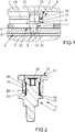
- FIG. 1 shows a locked in a frame 1 sash 2 of a window, a door, a French window or the like with a closure 3 of an unspecified espagnolette 4.
- the closure 3 has a riveted to a drive rod 5 locking pin 6 and a fixed in the frame 1 strike plate 7.
- the locking pin 6 has a cylindrical pin 8.
- the drive rod 5 is guided longitudinally displaceable in the wing 2 on a fixed face-plate 9.
- the faceplate 9 has a slot 10 for performing a foot portion 11 of the lock pin 6.
- a head portion 12 of the lock pin 6 is located with a cladding surface 13 at an edge 14 of the striker plate 7 at. Further shows FIG.
- the head part 12 is thus arranged eccentrically to the foot part 11. This allows the bias of the lateral surface 13 against the edge 14 by a rotation of the foot part 11 relative to the drive rod 5 change.
- the foot part 11 has a peripheral bearing collar 17, which slides over the face plate 9 during operation of the closure 3.
- the head part 12 has a mushroom head 18 which engages behind the edge 14 of the striking plate 7.
- FIG. 2 shows the locking pin 6 FIG. 1 in an enlarged sectional view.
- the head part 12 is designed sleeve-shaped and the foot part 11 has a shaft 19 for supporting the head part 12.
- the shaft 19 of the foot part 11 is longer than the shaft 19 directly opposite guide surface 20 of the head part 12, so that the head part 12 can be moved axially relative to the foot part 11.
- a arranged at the free end of the foot part 11 circumferential retaining collar 21 is produced by upsetting the shaft 19 and engages behind the head part 12. The circumferential retaining collar 21 thus forms a stop for the maximum axial displacement of the head part 12 relative to the foot part eleventh
- a bearing gap 22 Between the shaft 19 of the foot part 11 and the head part 12 is a bearing gap 22.
- a drain-proof, plastically deformable material 23 is arranged.
- the plastically deformable material 23 compensates for tolerances between the head part 12 and the foot part 11 and ensures sliding properties of the head part 12 with respect to the foot part 11.
- the plastically deformable material 23 holds the head part 12 in the set axial Location.
- the plastically deformable material 23 is a polyester resin, which is also used in practice for seals of motor housings.
- the foot part 11 also has an internal tooth 24 for attachment of a turning tool. This allows the bias of the head portion 12 against the in FIG. 1 set shown edge 14 of the striker plate 7.
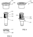
- FIG. 3 shows a further embodiment of a Schl thoroughlyzapfens 106 in an exploded view.
- This embodiment differs from that of FIG. 1 only in that a bearing collar 117 is disposed on an insert 125.
- To mount the insert 125 can be plugged onto a foot 111.
- a shaft 119 of the foot part 111 has an increased roughness 126 formed as a corrugation to increase the adhesion with plastically deformable material 123.
- the plastically deformable material 123 is shown only over a portion of the shaft 119.
- the plastically deformable material 123 passes, as in FIG. 2 shown in the assembled state in a bearing gap, not shown in this exploded view, between the head part 112 and shaft 119 of the foot part 111.
- FIG. 4 shows a further embodiment of the locking pin 206 in an exploded view.
- a foot 211 has on a shaft 219 a plurality of recesses 227, which are exemplary groove-shaped. These recesses 227 produce an increased adhesion of a plastically deformable material 223 on the shaft 219.
- the plastically deformable material 223 is also shown here only over a portion of the shaft 219 and passes, as in FIG. 2 shown in the assembled state between the head part 212 and shaft 219 of the foot part 211st
Landscapes
- Engineering & Computer Science (AREA)
- Mechanical Engineering (AREA)
- Lock And Its Accessories (AREA)
- Specific Sealing Or Ventilating Devices For Doors And Windows (AREA)
Abstract
Description
- Die Erfindung betrifft einen Schließzapfen für einen Verschluss eines Treibstangenbeschlages eines Fensters, einer Fenstertür oder dergleichen mit einem zur Befestigung an einer Treibstange des Treibstangenbeschlages vorgesehenen Fußteil, mit einem zum Eingreifen in ein Schließblech des Verschlusses vorgesehenen Kopfteil und mit einem Lagerspalt zwischen Fußteil und Kopfteil.
- Ein Schließzapfen mit einer auf einem Schaft gelagerten Pilzrolle ist beispielsweise aus der
DE 20 2012 000 211 U1 bekannt. Bei diesem Schließzapfen sichert ein Sprengring die axiale Lage der Pilzrolle auf dem Schaft. Der Sprengring ist in einem Lagerspalt zwischen Pilzrolle und Schaft angeordnet. Nachteilig bei dem bekannten Schließzapfen ist, dass Toleranzen zwischen Pilzrolle und Schaft zu einer erhöhten Betätigungskraft bei der Betätigung des Treibstangenbeschlages führen. Weiterhin können störende Geräusche entstehen. - Weiterhin ist aus der
EP 1 683 938 B1 ein Verschluss mit einem Schließzapfen bekannt geworden, bei dem das Kopfteil eine Übergangs- oder Presspassung in dem Fußteil hat. Hierdurch lässt sich die Höhe des Kopfteils durch Verschieben mit einem vorgesehenen Kraftaufwand einfach einstellen. Nachteilig bei diesem Schließzapfen ist jedoch, dass einer Drehbewegung des Kopfteils gegenüber dem Fußteil durch die Übergangs- oder Presspassung ein Widerstand entgegen gesetzt ist. Weiterhin erfordert die Übergangs- oder Presspassung sehr enge Toleranzen der Bauteile. - Der Erfindung liegt das Problem zugrunde, einen Schließzapfen der eingangs genannten Art so zu gestalten, dass Toleranzen zwischen Fußteil und Kopfteil einfach ausgeglichen werden.
- Dieses Problem wird erfindungsgemäß dadurch gelöst, dass in dem Lagerspalt ein ablauffestes, plastisch verformbares Material angeordnet ist.
- Durch diese Gestaltung gleicht das plastisch verformbare Material Toleranzen in dem Lagerspalt aus. Das Kopfteil wird daher in seiner axialen Lage gegenüber dem Fußteil gehalten. Jedoch ist das Material verformbar und stellt damit dauerhaft Schmiereigenschaften im Lagerspalt sicher. Das plastisch verformbare Material ermöglicht daher ein gleichmäßiges Abrollen des Kopfteils ohne Rattermarken oder Geräusche zu erzeugen. Dabei kann es genügen, dass das plastisch verformbare Material nur in einem Teilbereich des Lagerspaltes angeordnet ist. Vorzugsweise weist das Material über den für eine Tür oder ein Fenster typischen Temperaturbereich weitgehend konstante Eigenschaften auf.
- Ein Verkanten des Kopfteils auch bei großen Toleranzen im Lagerspalt lässt sich gemäß einer anderen vorteilhaften Weiterbildung der Erfindung zuverlässig verhindern, wenn sich das plastisch verformbare Material über die gesamte Höhe des Lagerspaltes erstreckt.
- Das plastisch verformbare Material vermag gemäß einer anderen vorteilhaften Weiterbildung der Erfindung eine Höhe des Kopfteils gegenüber dem Fußteil abzustützen, wenn der Lagerspalt als Axialführung des Kopfteils gegenüber dem Fußteil ausgebildet ist. Durch diese Gestaltung lässt sich das Kopfteil gegen die plastische Verformung des im Lagerspalt befindlichen Materials auf die vorgesehene Höhe einstellen. Dort verharrt das Kopfteil in seiner Position, da im Betrieb des Verschlusses keine Axialkräfte in das Kopfteil eingeleitet werden. Die Axialführung lässt sich konstruktiv besonders einfach erzeugen, wenn die an den Lagerspalt angrenzende Fläche des Fußteils länger ist als die des Kopfteils.
- Das Kopfteil lässt sich gemäß einer anderen vorteilhaften Weiterbildung der Erfindung besonders leichtgängig auf dem Fußteil abrollen, wenn das plastisch verformbare Material viskose Eigenschaften aufweist.
- Als plastisch verformbares Material lässt sich gemäß einer anderen vorteilhaften Weiterbildung der Erfindung kostengünstige Handelsware einsetzen, wenn das plastisch verformbare Material ein Polyesterharz ist. Ein solches Polyesterharz wird in der Praxis als dauerplastische Universaldichtung zur Abdichtung von Maschinen-, Getriebe- und Motorgehäusen eingesetzt und ist beispielsweise unter dem Handelsnamen Plast-o-Seal der Firma Weicon GmbH & Co KG bekannt.
- Ein Ablaufen des plastisch verformbaren Materials von dem Schließzapfen lässt sich gemäß einer anderen vorteilhaften Weiterbildung der Erfindung zuverlässig vermeiden, wenn zumindest eine der den Lagerspalt begrenzenden Fläche des Kopfteils oder des Fußteils eine hohe Rauigkeit zur Erhöhung der Adhäsion mit dem plastisch verformbaren Material aufweist.
- Zur Verbesserung der Ablauffestigkeit des plastisch verformbaren Materials trägt es gemäß einer anderen vorteilhaften Weiterbildung der Erfindung bei, wenn das Kopfteil oder das Fußteil Vertiefungen zur Erhöhung der Adhäsion mit dem plastisch verformbaren Material aufweist. Weiterhin ermöglicht diese Gestaltung eine Höhenfixierung des axial gegenüber dem Fußteil verschieblichen Kopfteils.
- Die axiale Beweglichkeit des Kopfteils lässt sich gemäß einer anderen vorteilhaften Weiterbildung der Erfindung einfach begrenzen, wenn das Fußteil an seinem freien Ende einen umlaufenden Haltebund zur Hintergreifung des Kopfteils hat.
- Zur Vereinfachung der Montage des Schließzapfens an der Treibstange trägt es gemäß einer anderen vorteilhaften Weiterbildung der Erfindung bei, wenn das Fußteil einen zur Befestigung an der Treibstange vorgesehenen Zapfen hat.
- Ein vorgesehener Anzug des Verschlusses lässt sich gemäß einer anderen vorteilhaften Weiterbildung der Erfindung einfach einstellen, wenn eine Achse des Kopfteils zu einer Achse des Fußteils versetzt ist. Durch diese Gestaltung lässt sich durch Verdrehen des Zapfens in der Treibstange die Vorspannung des Kopfteils gegenüber dem Schließblech verstellen.
- Die Erfindung lässt zahlreiche Ausführungsformen zu. Zur weiteren Verdeutlichung ihres Grundprinzips sind mehrere davon in der Zeichnung dargestellt und werden nachfolgend beschrieben. Diese zeigt in
- Fig. 1
- eine Schnittdarstellung eines Verschlusses,
- Fig. 2
- einen Längsschnitt durch einen Schließzapfen des Verschlusses aus
Figur 1 , - Fig. 3
- eine Explosionsdarstellung einer weiteren Ausführungsform des Schließzapfens,
- Fig. 4
- eine Explosionsdarstellung einer weiteren Ausführungsform des Schließzapfens.
-
Figur 1 zeigt einen in einem Rahmen 1 verriegelten Flügel 2 eines Fensters, einer Tür, einer Fenstertür oder dergleichen mit einem Verschluss 3 eines nicht näher dargestellten Treibstangenbeschlages 4. Der Verschluss 3 hat einen mit einer Treibstange 5 vernieteten Schließzapfen 6 und ein in dem Rahmen 1 befestigtes Schließblech 7. Zur Vernietung in der Treibstange 5 hat der Schließzapfen 6 einen zylindrischen Zapfen 8. Die Treibstange 5 ist im Flügel 2 an einer feststehenden Stulpschiene 9 längsverschieblich geführt. Die Stulpschiene 9 hat ein Langloch 10 zur Durchführung eines Fußteils 11 des Schließzapfens 6. Ein Kopfteil 12 des Schließzapfens 6 liegt mit einer Mantelfäche 13 an einer Kante 14 des Schließblechs 7 an. Weiterhin zeigtFigur 1 , dass eine Achse 15 des Fußteils 11 gegen über einer Achse 16 des Kopfteils 12 versetzt ist. Das Kopfteil 12 ist damit exzentrisch zum Fußteil 11 angeordnet. Damit lässt sich die Vorspannung der Mantelfläche 13 gegen die Kante 14 durch ein Verdrehen des Fußteils 11 gegenüber der Treibstange 5 verändern. Das Fußteil 11 hat einen umlaufenden Lagerbund 17, welcher im Betrieb des Verschlusses 3 über die Stulpschiene 9 gleitet. Das Kopfteil 12 hat einen Pilzkopf 18, welcher die Kante 14 des Schließblechs 7 hintergreift. -
Figur 2 zeigt den Schließzapfen 6 ausFigur 1 in einer vergrößerten Schnittdarstellung. Hierbei ist zu erkennen, dass das Kopfteil 12 hülsenförmig gestaltet ist und das Fußteil 11 einen Schaft 19 zur Lagerung des Kopfteils 12 hat. Der Schaft 19 des Fußteils 11 ist länger als eine dem Schaft 19 unmittelbar gegenüberstehende Führungsfläche 20 des Kopfteils 12, so dass sich das Kopfteil 12 axial gegenüber dem Fußteil 11 verschieben lässt. Ein an dem freien Ende des Fußteils 11 angeordneter umlaufender Haltebund 21 ist durch aufstauchen des Schaftes 19 erzeugt und hintergreift das Kopfteil 12. Der umlaufende Haltebund 21 bildet damit einen Anschlag für die maximale axiale Verschiebung des Kopfteils 12 gegenüber dem Fußteil 11. - Zwischen dem Schaft 19 des Fußteils 11 und dem Kopfteil 12 befindet sich ein Lagerspalt 22. In dem Lagerspalt 22 ist ein ablauffestes, plastisch verformbares Material 23 angeordnet. Das plastisch verformbare Material 23 gleicht Toleranzen zwischen Kopfteil 12 und Fußteil 11 aus und stellt Gleiteigenschaften des Kopfteils 12 gegenüber dem Fußteil 11 sicher. Zudem hält das plastisch verformbare Material 23 das Kopfteil 12 in der eingestellten axialen Lage. Das plastisch verformbare Material 23 ist ein Polyesterharz, welches in der Praxis auch für Abdichtungen von Motorengehäusen verwendet wird.
- Das Fußteil 11 hat zudem einen Innenvielzahn 24 zum Ansetzen eines Drehwerkzeuges. Damit lässt sich die Vorspannung des Kopfteils 12 gegen die in
Figur 1 dargestellte Kante 14 des Schließblechs 7 einstellen. -
Figur 3 zeigt eine weitere Ausführungsform eines Schleißzapfens 106 in einer Explosionsdarstellung. Diese Ausführungsform unterscheidet sich von der ausFigur 1 nur dadurch, dass ein Lagerbund 117 auf einem Einlegeteil 125 angeordnet ist. Zur Montage kann das Einlegeteil 125 auf einem Fußteil 111 aufgesteckt werden. Ein Schaft 119 des Fußteils 111 hat eine als Riffelung ausgebildete erhöhte Rauigkeit 126 zur Erhöhung der Adhäsion mit plastisch verformbaren Material 123. Zur Verdeutlichung ist das plastisch verformbare Material 123 nur über einem Teilbereich des Schaftes 119 dargestellt. Das plastisch verformbare Material 123 gelangt, wie inFigur 2 dargestellt, im montierten Zustand in einen in dieser Explosionsdarstellung nicht dargestellten Lagerspalt zwischen Kopfteil 112 und Schaft 119 des Fußteils 111. -
Figur 4 zeigt eine weitere Ausführungsform des Schließzapfens 206 in einer Explosionsdarstellung. Ein Fußteil 211 weist auf einem Schaft 219 mehrere Vertiefungen 227 auf, die beispielhaft rillenförmig sind. Diese Vertiefungen 227 erzeugen eine erhöhte Adhäsion eines plastisch verformbaren Materials 223 auf dem Schaft 219. Zur Verdeutlichung ist das plastisch verformbare Material 223 auch hier nur über einem Teilbereich des Schaftes 219 dargestellt und gelangt, wie inFigur 2 dargestellt, im montierten Zustand zwischen Kopfteil 212 und Schaft 219 des Fußteils 211.
Claims (10)
- Schließzapfen (6, 106, 206) für einen Verschluss (3) eines Treibstangenbeschlages (4) eines Fensters, einer Fenstertür oder dergleichen mit einem zur Befestigung an einer Treibstange (5) des Treibstangenbeschlages (4) vorgesehenen Fußteil (11, 111, 211), mit einem zum Eingreifen in ein Schließblech (7) des Verschlusses (3) vorgesehenen Kopfteil (12, 112, 212) und mit einem Lagerspalt (22) zwischen Fußteil (11, 111, 112) und Kopfteil (12, 112, 212), dadurch gekennzeichnet, dass in dem Lagerspalt (22) ein ablauffestes, plastisch verformbares Material (23, 123, 223) angeordnet ist.
- Schließzapfen nach Anspruch 1, dadurch gekennzeichnet, dass das plastisch verformbare Material (23, 123, 223) über die gesamte Höhe des Lagerspaltes (22) erstreckt.
- Schließzapfen nach Anspruch 1 oder 2, dadurch gekennzeichnet, dass der Lagerspalt (22) als Axialführung des Kopfteils (12, 112, 212) gegenüber dem Fußteil (11, 111, 112) ausgebildet ist.
- Schließzapfen nach zumindest einem der vorhergehenden Ansprüche, dadurch gekennzeichnet, dass das plastisch verformbare Material (23, 123, 223) viskose Eigenschaften aufweist.
- Schließzapfen nach zumindest einem der vorhergehenden Ansprüche, dadurch gekennzeichnet, dass das plastisch verformbare Material (23, 123, 223) ein Polyesterharz ist.
- Schließzapfen nach zumindest einem der vorhergehenden Ansprüche, dadurch gekennzeichnet, dass zumindest eine der den Lagerspalt (22) begrenzenden Fläche des Kopfteils (12, 112, 212) oder des Fußteils (11, 111, 112) eine hohe Rauhigkeit (126) zur Erhöhung der Adhäsion mit dem plastisch verformbaren Material (23, 123, 223) aufweist.
- Schließzapfen nach zumindest einem der vorhergehenden Ansprüche, dadurch gekennzeichnet, dass das Kopfteil (12, 112, 212) oder des Fußteil (11, 111, 112) Vertiefungen (227) zur Erhöhung der Adhäsion mit dem plastisch verformbaren Material (23, 123, 223) aufweist.
- Schließzapfen nach zumindest einem der vorhergehenden Ansprüche, dadurch gekennzeichnet, dass das Fußteil (11, 111, 112) an seinem freien Ende einen umlaufenden Haltebund (21, 121) zur Hintergreifung des Kopfteils (12, 112, 212) hat.
- Schließzapfen nach zumindest einem der vorhergehenden Ansprüche, dadurch gekennzeichnet, dass das Fußteil (11, 111, 112) einen zur Befestigung an der Treibstange (5) vorgesehenen Zapfen (8) hat.
- Schließzapfen nach zumindest einem der vorhergehenden Ansprüche, dadurch gekennzeichnet, dass eine Achse (16) des Kopfteils (12, 112, 212) zu einer Achse (15) des Fußteils (11, 111, 112) versetzt ist.
Applications Claiming Priority (1)
| Application Number | Priority Date | Filing Date | Title |
|---|---|---|---|
| DE102018203958.5A DE102018203958A1 (de) | 2018-03-15 | 2018-03-15 | Schließzapfen |
Publications (2)
| Publication Number | Publication Date |
|---|---|
| EP3540158A1 true EP3540158A1 (de) | 2019-09-18 |
| EP3540158B1 EP3540158B1 (de) | 2020-09-23 |
Family
ID=65628629
Family Applications (1)
| Application Number | Title | Priority Date | Filing Date |
|---|---|---|---|
| EP19159631.1A Active EP3540158B1 (de) | 2018-03-15 | 2019-02-27 | Schliesszapfen |
Country Status (3)
| Country | Link |
|---|---|
| EP (1) | EP3540158B1 (de) |
| DE (1) | DE102018203958A1 (de) |
| ES (1) | ES2828362T3 (de) |
Families Citing this family (1)
| Publication number | Priority date | Publication date | Assignee | Title |
|---|---|---|---|---|
| DE102022102457A1 (de) | 2022-02-02 | 2023-08-03 | Maco Technologie Gmbh | Adapterbeschlag für ein fenster oder eine tür zur realisierung einer sparlüftungsfunktion |
Citations (7)
| Publication number | Priority date | Publication date | Assignee | Title |
|---|---|---|---|---|
| DE2003284A1 (de) * | 1970-01-26 | 1971-08-26 | Schenning Theodor Karl Peter | Fenster- oder Tuerbeschlag |
| DE3009135A1 (de) * | 1980-03-10 | 1981-10-01 | Siegenia-Frank Kg, 5900 Siegen | Riegelzapfen fuer fluegelverschluesse von fenstern, tueren o.dgl. |
| DE3203421A1 (de) * | 1982-02-02 | 1983-08-11 | Wilhelm Weidtmann Gmbh & Co Kg, 5620 Velbert | Verfahren zum herstellen eines schliesszapfens fuer den beschlag von fenstern, tueren od.dgl. |
| DE202007010599U1 (de) * | 2007-07-12 | 2007-10-18 | Siegenia-Aubi Kg | Verschlussbolzen |
| GB2448340A (en) * | 2007-04-12 | 2008-10-15 | Avocet Hardware Ltd | A resilient keep arrangement |
| DE202012000211U1 (de) | 2012-01-11 | 2012-02-23 | Selve Fenstertechnik Gmbh | Vorrichtung zum einbruchsicheren Verschließen von Fenstern und Türen |
| EP1683938B1 (de) | 2005-01-18 | 2012-11-21 | Aug. Winkhaus GmbH & Co. KG | Verschluss für einen Treibstangenbeschlag |
-
2018
- 2018-03-15 DE DE102018203958.5A patent/DE102018203958A1/de not_active Withdrawn
-
2019
- 2019-02-27 EP EP19159631.1A patent/EP3540158B1/de active Active
- 2019-02-27 ES ES19159631T patent/ES2828362T3/es active Active
Patent Citations (7)
| Publication number | Priority date | Publication date | Assignee | Title |
|---|---|---|---|---|
| DE2003284A1 (de) * | 1970-01-26 | 1971-08-26 | Schenning Theodor Karl Peter | Fenster- oder Tuerbeschlag |
| DE3009135A1 (de) * | 1980-03-10 | 1981-10-01 | Siegenia-Frank Kg, 5900 Siegen | Riegelzapfen fuer fluegelverschluesse von fenstern, tueren o.dgl. |
| DE3203421A1 (de) * | 1982-02-02 | 1983-08-11 | Wilhelm Weidtmann Gmbh & Co Kg, 5620 Velbert | Verfahren zum herstellen eines schliesszapfens fuer den beschlag von fenstern, tueren od.dgl. |
| EP1683938B1 (de) | 2005-01-18 | 2012-11-21 | Aug. Winkhaus GmbH & Co. KG | Verschluss für einen Treibstangenbeschlag |
| GB2448340A (en) * | 2007-04-12 | 2008-10-15 | Avocet Hardware Ltd | A resilient keep arrangement |
| DE202007010599U1 (de) * | 2007-07-12 | 2007-10-18 | Siegenia-Aubi Kg | Verschlussbolzen |
| DE202012000211U1 (de) | 2012-01-11 | 2012-02-23 | Selve Fenstertechnik Gmbh | Vorrichtung zum einbruchsicheren Verschließen von Fenstern und Türen |
Also Published As
| Publication number | Publication date |
|---|---|
| DE102018203958A1 (de) | 2019-09-19 |
| ES2828362T3 (es) | 2021-05-26 |
| EP3540158B1 (de) | 2020-09-23 |
Similar Documents
| Publication | Publication Date | Title |
|---|---|---|
| EP2063155B1 (de) | Vorrichtung zur Drehsicherung eines axial beweglich an einem Montagebauteil gehaltenen Gleitringes einer Gleitringdichtungsanordnung | |
| EP1978187B1 (de) | Beschlaganordnung für ein Fenster, eine Tür oder dergleichen | |
| DE102007043391A1 (de) | Aktuator mit verlagerbarem Ausleger | |
| EP2546438B1 (de) | Zur verschieblichen Montage in einer einen Hinterschnitt aufweisenden Beschlagnut vorgesehenes Beschlagteil | |
| EP3540158A1 (de) | Schliesszapfen | |
| EP3809010A1 (de) | Reibungsdämpfer | |
| EP0713947B1 (de) | Drehbetätigungseinrichtung an einem Schaltgetriebe eines Fensters, einer Tür o.dgl. | |
| AT409023B (de) | Drehbetätigungseinrichtung | |
| DE10203006B4 (de) | Beschlag für einen Fahrzeugsitz | |
| EP1683938B1 (de) | Verschluss für einen Treibstangenbeschlag | |
| DE112014002753B4 (de) | Lenksäulenbaugruppe | |
| DE19601119C2 (de) | Drehbetätigungseinrichtung mit Blendhülse | |
| DE19909268B4 (de) | Verschluß zur Verriegelung eines schwenkbaren Flügels | |
| EP2343422A1 (de) | Beschlagbaugruppe für ein Fenster, eine Tür, eine Klappe oder dergleichen | |
| EP1757760B1 (de) | Beschlagteil für einen Treibstangenbeschlag | |
| EP1798360B1 (de) | Beschlagteil für einen Treibstangenbeschlag | |
| DE102016220854B4 (de) | Verstellvorrichtung | |
| EP3511491B1 (de) | Schliesszapfen für einen verschluss eines treibstangenbeschlages | |
| DE102019131900A1 (de) | Wellgetriebeanordnung | |
| DE9314325U1 (de) | Flügelscharnier | |
| EP0916791B1 (de) | Schliessmechanismus mit Führungsvorrichtung zum Führen eines längsbeweglich in einem Halteelement gehaltenen Stangenelements eines Schliessmechanismus | |
| DE19916940B4 (de) | Schließzapfen | |
| DE202004004769U1 (de) | Beschlaganordnung | |
| DE3009135A1 (de) | Riegelzapfen fuer fluegelverschluesse von fenstern, tueren o.dgl. | |
| EP1867818B1 (de) | Verschluss für einen Treibstangenbeschlag und Fenster, Fenstertür oder dergleichen mit einem solchen Verschluss |
Legal Events
| Date | Code | Title | Description |
|---|---|---|---|
| PUAI | Public reference made under article 153(3) epc to a published international application that has entered the european phase |
Free format text: ORIGINAL CODE: 0009012 |
|
| STAA | Information on the status of an ep patent application or granted ep patent |
Free format text: STATUS: THE APPLICATION HAS BEEN PUBLISHED |
|
| AK | Designated contracting states |
Kind code of ref document: A1 Designated state(s): AL AT BE BG CH CY CZ DE DK EE ES FI FR GB GR HR HU IE IS IT LI LT LU LV MC MK MT NL NO PL PT RO RS SE SI SK SM TR |
|
| AX | Request for extension of the european patent |
Extension state: BA ME |
|
| STAA | Information on the status of an ep patent application or granted ep patent |
Free format text: STATUS: REQUEST FOR EXAMINATION WAS MADE |
|
| GRAJ | Information related to disapproval of communication of intention to grant by the applicant or resumption of examination proceedings by the epo deleted |
Free format text: ORIGINAL CODE: EPIDOSDIGR1 |
|
| GRAP | Despatch of communication of intention to grant a patent |
Free format text: ORIGINAL CODE: EPIDOSNIGR1 |
|
| 17P | Request for examination filed |
Effective date: 20200220 |
|
| RBV | Designated contracting states (corrected) |
Designated state(s): AL AT BE BG CH CY CZ DE DK EE ES FI FR GB GR HR HU IE IS IT LI LT LU LV MC MK MT NL NO PL PT RO RS SE SI SK SM TR |
|
| GRAP | Despatch of communication of intention to grant a patent |
Free format text: ORIGINAL CODE: EPIDOSNIGR1 |
|
| STAA | Information on the status of an ep patent application or granted ep patent |
Free format text: STATUS: GRANT OF PATENT IS INTENDED |
|
| INTG | Intention to grant announced |
Effective date: 20200422 |
|
| GRAS | Grant fee paid |
Free format text: ORIGINAL CODE: EPIDOSNIGR3 |
|
| GRAA | (expected) grant |
Free format text: ORIGINAL CODE: 0009210 |
|
| STAA | Information on the status of an ep patent application or granted ep patent |
Free format text: STATUS: THE PATENT HAS BEEN GRANTED |
|
| AK | Designated contracting states |
Kind code of ref document: B1 Designated state(s): AL AT BE BG CH CY CZ DE DK EE ES FI FR GB GR HR HU IE IS IT LI LT LU LV MC MK MT NL NO PL PT RO RS SE SI SK SM TR |
|
| REG | Reference to a national code |
Ref country code: GB Ref legal event code: FG4D Free format text: NOT ENGLISH |
|
| REG | Reference to a national code |
Ref country code: CH Ref legal event code: EP |
|
| REG | Reference to a national code |
Ref country code: DE Ref legal event code: R096 Ref document number: 502019000242 Country of ref document: DE |
|
| REG | Reference to a national code |
Ref country code: IE Ref legal event code: FG4D Free format text: LANGUAGE OF EP DOCUMENT: GERMAN |
|
| REG | Reference to a national code |
Ref country code: AT Ref legal event code: REF Ref document number: 1316528 Country of ref document: AT Kind code of ref document: T Effective date: 20201015 |
|
| REG | Reference to a national code |
Ref country code: SE Ref legal event code: TRGR |
|
| PG25 | Lapsed in a contracting state [announced via postgrant information from national office to epo] |
Ref country code: HR Free format text: LAPSE BECAUSE OF FAILURE TO SUBMIT A TRANSLATION OF THE DESCRIPTION OR TO PAY THE FEE WITHIN THE PRESCRIBED TIME-LIMIT Effective date: 20200923 Ref country code: NO Free format text: LAPSE BECAUSE OF FAILURE TO SUBMIT A TRANSLATION OF THE DESCRIPTION OR TO PAY THE FEE WITHIN THE PRESCRIBED TIME-LIMIT Effective date: 20201223 Ref country code: GR Free format text: LAPSE BECAUSE OF FAILURE TO SUBMIT A TRANSLATION OF THE DESCRIPTION OR TO PAY THE FEE WITHIN THE PRESCRIBED TIME-LIMIT Effective date: 20201224 Ref country code: FI Free format text: LAPSE BECAUSE OF FAILURE TO SUBMIT A TRANSLATION OF THE DESCRIPTION OR TO PAY THE FEE WITHIN THE PRESCRIBED TIME-LIMIT Effective date: 20200923 Ref country code: BG Free format text: LAPSE BECAUSE OF FAILURE TO SUBMIT A TRANSLATION OF THE DESCRIPTION OR TO PAY THE FEE WITHIN THE PRESCRIBED TIME-LIMIT Effective date: 20201223 |
|
| PG25 | Lapsed in a contracting state [announced via postgrant information from national office to epo] |
Ref country code: LV Free format text: LAPSE BECAUSE OF FAILURE TO SUBMIT A TRANSLATION OF THE DESCRIPTION OR TO PAY THE FEE WITHIN THE PRESCRIBED TIME-LIMIT Effective date: 20200923 Ref country code: RS Free format text: LAPSE BECAUSE OF FAILURE TO SUBMIT A TRANSLATION OF THE DESCRIPTION OR TO PAY THE FEE WITHIN THE PRESCRIBED TIME-LIMIT Effective date: 20200923 |
|
| REG | Reference to a national code |
Ref country code: NL Ref legal event code: MP Effective date: 20200923 |
|
| REG | Reference to a national code |
Ref country code: LT Ref legal event code: MG4D |
|
| PG25 | Lapsed in a contracting state [announced via postgrant information from national office to epo] |
Ref country code: SM Free format text: LAPSE BECAUSE OF FAILURE TO SUBMIT A TRANSLATION OF THE DESCRIPTION OR TO PAY THE FEE WITHIN THE PRESCRIBED TIME-LIMIT Effective date: 20200923 Ref country code: LT Free format text: LAPSE BECAUSE OF FAILURE TO SUBMIT A TRANSLATION OF THE DESCRIPTION OR TO PAY THE FEE WITHIN THE PRESCRIBED TIME-LIMIT Effective date: 20200923 Ref country code: PT Free format text: LAPSE BECAUSE OF FAILURE TO SUBMIT A TRANSLATION OF THE DESCRIPTION OR TO PAY THE FEE WITHIN THE PRESCRIBED TIME-LIMIT Effective date: 20210125 Ref country code: RO Free format text: LAPSE BECAUSE OF FAILURE TO SUBMIT A TRANSLATION OF THE DESCRIPTION OR TO PAY THE FEE WITHIN THE PRESCRIBED TIME-LIMIT Effective date: 20200923 Ref country code: CZ Free format text: LAPSE BECAUSE OF FAILURE TO SUBMIT A TRANSLATION OF THE DESCRIPTION OR TO PAY THE FEE WITHIN THE PRESCRIBED TIME-LIMIT Effective date: 20200923 Ref country code: EE Free format text: LAPSE BECAUSE OF FAILURE TO SUBMIT A TRANSLATION OF THE DESCRIPTION OR TO PAY THE FEE WITHIN THE PRESCRIBED TIME-LIMIT Effective date: 20200923 |
|
| REG | Reference to a national code |
Ref country code: ES Ref legal event code: FG2A Ref document number: 2828362 Country of ref document: ES Kind code of ref document: T3 Effective date: 20210526 |
|
| PG25 | Lapsed in a contracting state [announced via postgrant information from national office to epo] |
Ref country code: AL Free format text: LAPSE BECAUSE OF FAILURE TO SUBMIT A TRANSLATION OF THE DESCRIPTION OR TO PAY THE FEE WITHIN THE PRESCRIBED TIME-LIMIT Effective date: 20200923 Ref country code: PL Free format text: LAPSE BECAUSE OF FAILURE TO SUBMIT A TRANSLATION OF THE DESCRIPTION OR TO PAY THE FEE WITHIN THE PRESCRIBED TIME-LIMIT Effective date: 20200923 Ref country code: IS Free format text: LAPSE BECAUSE OF FAILURE TO SUBMIT A TRANSLATION OF THE DESCRIPTION OR TO PAY THE FEE WITHIN THE PRESCRIBED TIME-LIMIT Effective date: 20210123 |
|
| REG | Reference to a national code |
Ref country code: DE Ref legal event code: R097 Ref document number: 502019000242 Country of ref document: DE |
|
| PG25 | Lapsed in a contracting state [announced via postgrant information from national office to epo] |
Ref country code: SK Free format text: LAPSE BECAUSE OF FAILURE TO SUBMIT A TRANSLATION OF THE DESCRIPTION OR TO PAY THE FEE WITHIN THE PRESCRIBED TIME-LIMIT Effective date: 20200923 |
|
| PLBE | No opposition filed within time limit |
Free format text: ORIGINAL CODE: 0009261 |
|
| STAA | Information on the status of an ep patent application or granted ep patent |
Free format text: STATUS: NO OPPOSITION FILED WITHIN TIME LIMIT |
|
| PG25 | Lapsed in a contracting state [announced via postgrant information from national office to epo] |
Ref country code: DK Free format text: LAPSE BECAUSE OF FAILURE TO SUBMIT A TRANSLATION OF THE DESCRIPTION OR TO PAY THE FEE WITHIN THE PRESCRIBED TIME-LIMIT Effective date: 20200923 Ref country code: SI Free format text: LAPSE BECAUSE OF FAILURE TO SUBMIT A TRANSLATION OF THE DESCRIPTION OR TO PAY THE FEE WITHIN THE PRESCRIBED TIME-LIMIT Effective date: 20200923 |
|
| 26N | No opposition filed |
Effective date: 20210624 |
|
| PG25 | Lapsed in a contracting state [announced via postgrant information from national office to epo] |
Ref country code: MC Free format text: LAPSE BECAUSE OF FAILURE TO SUBMIT A TRANSLATION OF THE DESCRIPTION OR TO PAY THE FEE WITHIN THE PRESCRIBED TIME-LIMIT Effective date: 20200923 |
|
| PG25 | Lapsed in a contracting state [announced via postgrant information from national office to epo] |
Ref country code: LU Free format text: LAPSE BECAUSE OF NON-PAYMENT OF DUE FEES Effective date: 20210227 |
|
| PG25 | Lapsed in a contracting state [announced via postgrant information from national office to epo] |
Ref country code: IE Free format text: LAPSE BECAUSE OF NON-PAYMENT OF DUE FEES Effective date: 20210227 |
|
| REG | Reference to a national code |
Ref country code: CH Ref legal event code: PL |
|
| PG25 | Lapsed in a contracting state [announced via postgrant information from national office to epo] |
Ref country code: LI Free format text: LAPSE BECAUSE OF NON-PAYMENT OF DUE FEES Effective date: 20220228 Ref country code: CH Free format text: LAPSE BECAUSE OF NON-PAYMENT OF DUE FEES Effective date: 20220228 |
|
| P01 | Opt-out of the competence of the unified patent court (upc) registered |
Effective date: 20230516 |
|
| PG25 | Lapsed in a contracting state [announced via postgrant information from national office to epo] |
Ref country code: NL Free format text: LAPSE BECAUSE OF NON-PAYMENT OF DUE FEES Effective date: 20200923 Ref country code: CY Free format text: LAPSE BECAUSE OF FAILURE TO SUBMIT A TRANSLATION OF THE DESCRIPTION OR TO PAY THE FEE WITHIN THE PRESCRIBED TIME-LIMIT Effective date: 20200923 |
|
| PG25 | Lapsed in a contracting state [announced via postgrant information from national office to epo] |
Ref country code: HU Free format text: LAPSE BECAUSE OF FAILURE TO SUBMIT A TRANSLATION OF THE DESCRIPTION OR TO PAY THE FEE WITHIN THE PRESCRIBED TIME-LIMIT; INVALID AB INITIO Effective date: 20190227 |
|
| GBPC | Gb: european patent ceased through non-payment of renewal fee |
Effective date: 20230227 |
|
| PG25 | Lapsed in a contracting state [announced via postgrant information from national office to epo] |
Ref country code: GB Free format text: LAPSE BECAUSE OF NON-PAYMENT OF DUE FEES Effective date: 20230227 |
|
| PG25 | Lapsed in a contracting state [announced via postgrant information from national office to epo] |
Ref country code: GB Free format text: LAPSE BECAUSE OF NON-PAYMENT OF DUE FEES Effective date: 20230227 |
|
| PG25 | Lapsed in a contracting state [announced via postgrant information from national office to epo] |
Ref country code: MK Free format text: LAPSE BECAUSE OF FAILURE TO SUBMIT A TRANSLATION OF THE DESCRIPTION OR TO PAY THE FEE WITHIN THE PRESCRIBED TIME-LIMIT Effective date: 20200923 |
|
| PG25 | Lapsed in a contracting state [announced via postgrant information from national office to epo] |
Ref country code: MT Free format text: LAPSE BECAUSE OF FAILURE TO SUBMIT A TRANSLATION OF THE DESCRIPTION OR TO PAY THE FEE WITHIN THE PRESCRIBED TIME-LIMIT Effective date: 20200923 |
|
| REG | Reference to a national code |
Ref country code: DE Ref legal event code: R081 Ref document number: 502019000242 Country of ref document: DE Owner name: AUG. WINKHAUS SE & CO. KG, DE Free format text: FORMER OWNER: AUG. WINKHAUS GMBH & CO. KG, 48291 TELGTE, DE Ref country code: DE Ref legal event code: R081 Ref document number: 502019000242 Country of ref document: DE Owner name: AUG. WINKHAUS SE, DE Free format text: FORMER OWNER: AUG. WINKHAUS GMBH & CO. KG, 48291 TELGTE, DE |
|
| REG | Reference to a national code |
Ref country code: DE Ref legal event code: R081 Ref document number: 502019000242 Country of ref document: DE Owner name: AUG. WINKHAUS SE, DE Free format text: FORMER OWNER: AUG. WINKHAUS SE & CO. KG, 48291 TELGTE, DE |
|
| PG25 | Lapsed in a contracting state [announced via postgrant information from national office to epo] |
Ref country code: TR Free format text: LAPSE BECAUSE OF FAILURE TO SUBMIT A TRANSLATION OF THE DESCRIPTION OR TO PAY THE FEE WITHIN THE PRESCRIBED TIME-LIMIT Effective date: 20200923 |
|
| PGFP | Annual fee paid to national office [announced via postgrant information from national office to epo] |
Ref country code: SE Payment date: 20260218 Year of fee payment: 8 |
|
| PGFP | Annual fee paid to national office [announced via postgrant information from national office to epo] |
Ref country code: ES Payment date: 20260319 Year of fee payment: 8 |
|
| PGFP | Annual fee paid to national office [announced via postgrant information from national office to epo] |
Ref country code: DE Payment date: 20260217 Year of fee payment: 8 |
|
| PGFP | Annual fee paid to national office [announced via postgrant information from national office to epo] |
Ref country code: AT Payment date: 20260216 Year of fee payment: 8 |
|
| PGFP | Annual fee paid to national office [announced via postgrant information from national office to epo] |
Ref country code: BE Payment date: 20260218 Year of fee payment: 8 Ref country code: IT Payment date: 20260227 Year of fee payment: 8 |
|
| PGFP | Annual fee paid to national office [announced via postgrant information from national office to epo] |
Ref country code: FR Payment date: 20260219 Year of fee payment: 8 |