EP3539854A1 - Rear brake hose layout structure for saddle riding vehicle - Google Patents
Rear brake hose layout structure for saddle riding vehicle Download PDFInfo
- Publication number
- EP3539854A1 EP3539854A1 EP19159858.0A EP19159858A EP3539854A1 EP 3539854 A1 EP3539854 A1 EP 3539854A1 EP 19159858 A EP19159858 A EP 19159858A EP 3539854 A1 EP3539854 A1 EP 3539854A1
- Authority
- EP
- European Patent Office
- Prior art keywords
- brake hose
- swing arm
- hose
- disposed
- brake
- Prior art date
- Legal status (The legal status is an assumption and is not a legal conclusion. Google has not performed a legal analysis and makes no representation as to the accuracy of the status listed.)
- Granted
Links
- 239000000725 suspension Substances 0.000 claims description 32
- 239000002184 metal Substances 0.000 claims description 18
- 230000001681 protective effect Effects 0.000 claims description 5
- 238000005452 bending Methods 0.000 description 5
- 230000009191 jumping Effects 0.000 description 3
- 230000002411 adverse Effects 0.000 description 2
- 229910000831 Steel Inorganic materials 0.000 description 1
- 238000002485 combustion reaction Methods 0.000 description 1
- 230000000694 effects Effects 0.000 description 1
- 230000014509 gene expression Effects 0.000 description 1
- 238000012986 modification Methods 0.000 description 1
- 230000004048 modification Effects 0.000 description 1
- 238000007665 sagging Methods 0.000 description 1
- 239000010959 steel Substances 0.000 description 1
Images


Classifications
-
- B—PERFORMING OPERATIONS; TRANSPORTING
- B62—LAND VEHICLES FOR TRAVELLING OTHERWISE THAN ON RAILS
- B62J—CYCLE SADDLES OR SEATS; AUXILIARY DEVICES OR ACCESSORIES SPECIALLY ADAPTED TO CYCLES AND NOT OTHERWISE PROVIDED FOR, e.g. ARTICLE CARRIERS OR CYCLE PROTECTORS
- B62J15/00—Mud-guards for wheels
Definitions
- the present invention relates to a rear brake hose layout structure for a saddle riding vehicle.
- Rear brake devices for motorcycles include a brake pedal disposed on the right side in a transverse direction of a vehicle body frame.
- a brake hose extends from a master cylinder coupled to the brake pedal to a rear end portion of a swing arm that supports a rear wheel, where the brake hose is coupled to a brake caliper.
- a brake hose passage interconnecting a master cylinder coupled to a brake pedal and a caliper extends forwardly of the pivoted portion of a swing arm.
- Patent Document 1 Japanese Patent Laid-open No. 2006-21628
- Patent Document 1 discloses that a brake hose is disposed on a swing arm and has a large part exposed to the tread of a rear wheel as viewed in a side elevation of the vehicle.
- a rear brake hose layout structure for a saddle riding vehicle including: a swing arm (12) including an arm body (12a), a pivot portion (12c), and an intermediate portion (12b) that interconnects the arm body (12a) and the pivot portion (12c); a brake hose (40) having at least a portion disposed on an upper surface of the swing arm (12); and a fender (31) mounted on the swing arm (12) and covering the swing arm (12) and a rear wheel (3) from above.
- the fender (31) has a forward extension (31a) covering at least a portion of an upper surface of the intermediate portion (12b) of the swing arm (12), and the forward extension (31a) overlaps the brake hose (40) as viewed in side elevation.
- the rear brake hose layout structure may further include a suspension (27) having a lower end (27a) connected to a central rear portion (12f) of the intermediate portion (12b) of the swing arm (12).
- the swing arm (12) may include a side wall (12e) disposed on a side of the intermediate portion (12b) and extending upwardly, and the brake hose (40) may lie between the suspension (27) and the side wall (12e).
- the fender (31) may have a recess (31c), a gap (50) which does not overlap the swing arm (12) as viewed in plan may be defined rearwardly of the intermediate portion (12b) of the swing arm (12), and the brake hose (40) may extend through the gap (50) and may be disposed inwardly of the arm body (12a).
- the swing arm (12) may have a bent portion (12d) on a junction, which faces the rear wheel (3), between the intermediate portion (12b) and the arm body (12a), and the fender (31) may be disposed above and cover a portion of the brake hose (40) that is disposed along the bent portion (12d).
- the portion of the brake hose (40) that is disposed along the bent portion (12d) may include at least a portion constructed as a metal pipe (46), and the brake hose (40) may include a combination of the metal pipe (46) and a hose (41, 44, 48).
- the rear brake hose layout structure may further include a protective member (52) disposed between the portion of the brake hose (40) that is disposed along the bent portion (12d) and the rear wheel (3).
- the brake hose (40) may have a joint (45) interconnecting the hose (41, 44, 48) and the metal pipe (46), and the joint (45) may be offset rearwardly from a maximum-diameter portion (27b) of the suspension (27).
- the rear brake hose layout structure for a saddle riding vehicle includes: a swing arm including an arm body, a pivot portion, and an intermediate portion that interconnects the arm body and the pivot portion; a brake hose having at least a portion disposed on an upper surface of the swing arm; and a fender mounted on the swing arm and covering the swing arm and a rear wheel from above, the fender having a forward extension covering at least a portion of an upper surface of the intermediate portion of the swing arm, the forward extension overlapping the brake hose as viewed in side elevation.
- the fender blocks jumping pebbles ahead of the intermediate portion of the swing arm, protecting the brake hose over the upper surface of the intermediate portion from pebbles. Since the forward extension of the fender conceals the brake hose as viewed in side elevation, the appearance of the vehicle is improved.
- the rear brake hose layout structure includes a suspension having a lower end connected to a central rear portion of the intermediate portion of the swing arm, the swing arm including a linear protruding portion disposed on a side of the intermediate portion and extending longitudinally of the vehicle, the brake hose lying between the suspension and the linear protruding portion.
- the brake hose is concealed by the linear protruding portion and is less visible sideways with respect to the vehicle. As the brake hose lies between the suspension and the linear protruding portion, the brake hose can be disposed in a position that is less visible. The layout of the brake hose does not adversely affect the behavior of the suspension.
- the fender has a recess, a gap which does not overlap the swing arm as viewed in plan is defined rearwardly of the intermediate portion of the swing arm, and the brake hose extends through the gap and is disposed inwardly of the arm body.
- the brake hose can be placed forwardly of the intermediate portion of the swing arm that is protected from jumping pebbles by the fender, and can be disposed inwardly of the arm body without extending around the fender.
- the overall length of the brake hose is not increased, and the brake hose is disposed within the swing arm and is less visible, thereby improving the appearance of the vehicle.
- the swing arm has a bent portion on a junction, which faces the rear wheel, between the intermediate portion and the arm body, and the fender is disposed above and covers a portion of the brake hose that is disposed along the bent portion. Therefore, the fender conceals the brake hose disposed along the bent portion, thereby improving the appearance of the vehicle.
- the portion of the brake hose that is disposed along the bent portion includes at least a portion constructed as a metal pipe, and the brake hose includes a combination of the metal pipe and a hose.
- the brake hose can be placed in a small space, using the metal pipe that is smaller in outside diameter than hoses and has a smaller allowable bending radius than the hoses. The freedom with which to lay the brake hose in position is increased, and the appearance of the vehicle is improved by concealing the brake hose.
- the rear brake hose layout structure further includes a protective member disposed between the portion of the brake hose that is disposed along the bent portion and the rear wheel.
- the protective member thus disposed protects the portion of the brake hose disposed along the bent portion. The appearance of the vehicle is thus improved by placing the brake hose along the bent portion and hence concealing and protecting the brake hose.
- the brake hose has a joint interconnecting the hose and the metal pipe, and the joint is offset rearwardly from a maximum-diameter portion of the suspension.
- the joint reliably holds the metal pipe, and is held out of contact with the suspension. Therefore, the joint does not adversely affect the behavior of the suspension.
- the brake hose that is placed over the upper surface of the swing arm is less visible from outside of the vehicle, thereby improving the appearance of the vehicle.
- a rear brake hose layout structure according to an embodiment of the present invention will hereinafter be described with reference to the drawings.
- directions such as forward, rearward, leftward, rightward, upward, and downward directions and other directional expressions shall be in accord with those with respect to a vehicle body unless specified otherwise.
- the reference symbols FR represent a forward direction, UP an upward direction, and LH a leftward direction.
- FIG. 1 is a right side elevational view of a motorcycle 1 according to an embodiment of the present invention.
- FIG. 2 is a fragmentary right side elevational view illustrating an inner fender mount portion of a swing arm. Of all components of the motorcycle 1 that are available in pairs of left and right components, only those disposed on the right side of the motorcycle, together with reference symbols representing them, are illustrated in FIG. 1 .
- the motorcycle 1 includes an engine 10 as a power unit supported on a vehicle body frame F and a front wheel 2 and a rear wheel 3 that are disposed respectively in front and rear positions.
- the front wheel 2 is supported on a front fork 11 steerably supported on a front end of the vehicle body frame F.
- the rear wheel 3 is supported on a swing arm 12 disposed on a rear portion of the vehicle body frame F.
- the motorcycle 1 is a saddle riding vehicle that includes a seat 13 that the rider sits astride.
- the seat 13 is disposed on an upper surface of the rear portion of the vehicle body frame F.
- the vehicle body frame F includes a pair of left and right main frames 18 that support the engine 10 in the form of an internal combustion engine, and a rear frame 16 extending rearwardly from the main frames 18.
- a head pipe 17 is connected to front ends of the main frames 18.
- the main frames 18 include a pair of left and right main tubes 22 extending rearwardly and downwardly from a rear surface of the head pipe 17, and a pair of left and right pivot frames 23 extending downwardly from rear ends of the main tubes 22.
- the main tubes 22 that extend rearwardly and downwardly have respective front end portions that are spaced from each other by a larger distance transversely across the vehicle body frame F and respective rear end portions that are spaced from each other by a smaller distance transversely across the vehicle body frame F.
- the pivot frames 23 are connected to each other by a cross member, not depicted, that extends transversely across the vehicle body frame F.
- the front fork 11 is supported by a steering shaft, not depicted, pivotally supported by the head pipe 17, a top bridge 24 fixed to an upper end of the steering shaft, and a bottom bridge 25 fixed to a lower end of the steering shaft.
- the front wheel 2 is rotatably supported on a lower end portion of the front fork 11.
- a handle 21 that is used by the rider to steer the front wheel 2 is mounted on the top bridge 24.
- the swing arm 12 extends rearwardly from the main frames 18 has a front end portion pivotally supported on a pivot shaft 26 disposed on the pivot frames 23 and extending transversely across the vehicle body frame F.
- the swing arm 12 is vertically swingable about the pivot shaft 26.
- the rear wheel 3 is rotatably supported on a rear end portion of the swing arm 12.
- a suspension 27 as a damper device is disposed between and coupled to the swing arm 12 and the main frames 18.
- the engine 10 is supported on the main frames 18. Output power from the engine 10 is available from an output shaft thereof that projects on the left side of the motorcycle 1, and is transmitted to the rear wheel 3 by a chain, not depicted, that is trained around a sprocket on the output shaft of the engine 10 and a sprocket on the rear wheel 3.
- the engine 10 includes an exhaust pipe 28 extending forwardly from an exhaust port on a front surface of the engine 10, then extends transversely to one side, i.e., the right side, of the motorcycle 1, and then extends rearwardly.
- the exhaust pipe 28 has a rear end connected to a muffler 29.
- a pair of steps 32 are disposed respectively on the left and right sides of the motorcycle 1 below the pivot frames 23.
- a shift pedal not depicted, is disposed in the vicinity of the step 32 on the left side of the motorcycle 1.
- a brake pedal 33 is disposed in the vicinity of the step 32 on the right side of the motorcycle 1.
- the motorcycle 1 includes a front fender 2a mounted on the front fork 11 in covering relation to an upper portion of the front wheel 2, and a rear fender 3a extending in overhanging relation to the rear wheel 3.
- An inner fender 31 that covers an upper portion of the rear wheel 3 is mounted on the swing arm 12 below the rear fender 3a.
- a brake caliper 11a is mounted on the front fork 11 for braking the front wheel 2 in response to operation of a brake lever, not depicted, mounted on the handle 21.
- a brake caliper 34 is mounted on a rear portion of the swing arm 12 disposed on the right side of the motorcycle 1 for braking the rear wheel 3 in response to operation of the brake pedal 33.
- a master cylinder 35 is connected to the brake pedal 33 through a link rod 33a.
- the master cylinder 35 is connected to the brake caliper 34 for braking the rear wheel 3 by a brake hose 40.
- the master cylinder 35 is mounted on a plate 23b that is mounted on the right pivot frame 23.
- the master cylinder 35 has an upper portion inclined forwardly and is connected to a hose 41 of the brake hose 40 and a reservoir hose 42.
- the hose 41 is connected to an upper end portion of the master cylinder 35.
- the master cylinder 35 transmits hydraulic pressure through the hose 41 to working oil in the brake hose 40, transmitting the operation of the brake pedal 33 to the brake caliper 34.
- the reservoir hose 42 is connected to a vertically intermediate portion of the master cylinder 35, which is connected to an oil reservoir, not depicted, through the reservoir hose 42.
- the master cylinder 35 is replenished with working oil from the oil reservoir through the reservoir hose 42.
- FIG. 3 is a fragmentary plan view, partly cross section, illustrating a suspension mount portion of the swing arm 12.
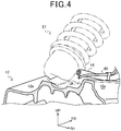
- FIG. 4 is a fragmentary perspective view, partly cross section, illustrating the shape of an upper surface of the swing arm 12.
- FIG. 5 is a fragmentary perspective view illustrating the layout of the brake hose 40 on a bent portion of the swing arm 12.
- FIG. 6 is a perspective view illustrating the connected configuration of the brake hose 40.
- the brake hose 40 includes the hose 41 connected to the master cylinder 35, a first joint 43, a front hose 44, a second joint 45, a pipe 46, a third joint 47, and a rear hose 48.
- the hose 41, the front hose 44, and the rear hose 48 are pressure-resistant rubber hoses.
- the first joint 43 and the second joint 45 are metal members.
- the hose 41 interconnects the master cylinder 35 and the first joint 43 that is mounted on the right main frame 18 above a pair of left and right front pivot portions 12c of the swing arm 12.
- the front hose 44 has a front end connected to the first joint 43 and extends rearwardly with respect to the motorcycle 1.
- the front hose 44 has a rear end connected to the second joint 45.
- the pipe 46 in the form of a metal pipe has a front end connected to the second joint 45 and a rear end connected to the third joint 47.
- the pipe 46 which may be a steel pipe or the like, has an outside diameter smaller than the pressure-resistant rubber hoses that have a pressure-resistant capability equivalent to the pipe 46.
- the pipe 46 can have an allowable bending radius smaller than the pressure-resistant rubber hoses.
- the rear hose 48 has a front end connected to the third joint 47 and a rear end connected to the brake caliper 34.
- the master cylinder 35 is thus connected to the brake caliper 34 by the brake hose 40, so that the brake caliper 34 can be hydraulically operated when the master cylinder 35 is operated by the brake pedal 33.
- the anti-lock brake system has a valve unit, not depicted, and a power module, not depicted, that are connected to the first joint 43.
- the anti-lock brake system controls braking forces generated by the brake caliper 34 depending on the vehicle speed detected by a vehicle speed sensor, not depicted, on the motorcycle 1.
- the anti-lock brake system is effective to prevent the rear wheel 3 from being locked, thereby keeping the motorcycle 1 stable in its direction of travel.
- the front pivot portions 12c of the swing arm 12 are pivotally connected to the respective pivot frames 23 by the pivot shaft 26.
- the left and right front pivot portions 12c are disposed in left and right positions on the motorcycle 1 and have respective rear portions connected to an intermediate portion 12b.
- the intermediate portion 12b joins the left and right front pivot portions 12c to each other, and has a pair of left and right suspension supports 12g centrally on a rear portion thereof.
- the suspension 27 has a lower end 27a swingably supported between the left and right suspension supports 12g.
- the swing arm 12 has a pair of left and right arm bodies 12a having respective front ends connected to left and right sides of the rear portion of the intermediate portion 12b.
- the rear wheel 3 is rotatably supported between respective rear end portions of the left and right arm bodies 12a.
- the swing arm 12 has on an upper surface thereof a side wall 12e of the motorcycle 1 that extends from the right pivot portion 12c to the intermediate portion 12b.
- the side wall 12e increases the vertical effective cross-sectional area of a rear portion of the pivot portion 12c, thereby increasing the vertical flexural rigidity of the swing arm 12.
- the junction between the intermediate portion 12b and the right arm body 12a has a bent portion 12d on a side thereof which faces the rear wheel 3, i.e., on an inner side extending transversely of the motorcycle 1.
- the bent portion 12d has an arcuate surface that is recessed obliquely rightwardly and forwardly, smoothly joining a rear surface of the intermediate portion 12b and a left side surface of the right arm body 12a as viewed in plan.
- the inner fender 31 is mounted on an upper surface of the swing arm 12 and covers a front upper portion of the rear wheel 3.
- the inner fender 31 is in the form of a plate extending obliquely rearwardly and upwardly and has a transversely central portion protruding upwardly.
- the inner fender 31 includes a forward extension 31a on a right side thereof, extending forwardly over the intermediate portion 12b of the swing arm 12.
- the forward extension 31a extends along the direction in which the side wall 12e of the swing arm 12 extends.
- the inner fender 31 is disposed such that a front portion of the forward extension 31a overlaps part of a rear portion of the side wall 12e.
- the inner fender 31 includes a central arcuate portion 31b that protrudes forwardly and extends along part of an outer circumferential surface of the rear wheel 3.
- the arcuate portion 31b has a distal end substantially aligned with a rear surface of the intermediate portion 12b as viewed in plan.
- a recess 31c is defined between the forward extension 31a and the arcuate portion 31b.
- a gap 50 is defined between the rear surface of the intermediate portion 12b and the recess 31c in the inner fender 31 as viewed in plan.
- the pipe 46 of the brake hose 40 extends rearwardly through the gap 50.
- the first joint 43 of the brake hose 40 is mounted on the right main frame 18 above the right pivot portion 12c of the swing arm 12.
- the front hose 44 extends from an upper surface of the right pivot portion 12c along a left side of the side wall 12e and is disposed inwardly of left and right outer side surfaces of the swing arm 12.
- the second joint 45 is disposed on an upper surface of the rear portion of the intermediate portion 12b of the swing arm 12.
- the second joint 45 is disposed between the suspension 27 and the forward extension 31a of the inner fender 31 as viewed in plan.
- the second joint 45 is fixed to an upper portion of a right side surface of the intermediate portion 12b by a stay 51. As illustrated in FIG. 2 , the second joint 45 is disposed so as not overlap an adjustment ring 27b that is a maximum-diameter portion of the suspension 27 as viewed in side elevation. In other words, the second joint 45 is offset rearwardly from the adjustment ring 27b.
- the second joint 45 is disposed such that a portion of the second joint 45 overlaps the forward extension 31a as viewed in side elevation.
- the stay 51 by which the second joint 45 is fixed to the intermediate portion 12b extends leftwardly from the upper portion of the right side surface of the intermediate portion 12b, and extends below the forward extension 31a over an upper surface of the swing arm 12.
- the stay 51 thus allows the second joint 45 to be disposed leftwardly of the forward extension 31a.
- the front hose 44 that interconnects the first joint 43 and the second joint 45 extends longitudinally along a left side surface 12f of the side wall 12e.
- the front hose 44 lies between the forward extension 31a and the suspension 27, and includes a portion overlapping the forward extension 31a as viewed in side elevation.
- the pipe 46 is connected to the second joint 45. As illustrated in FIG. 5 , the pipe 46 extends from the upper surface of the rear portion of the intermediate portion 12b downwardly through the gap 50 between the inner fender 31 and the rear surface of the intermediate portion 12b. The pipe 46 then extends from the upper surface of the rear portion of the intermediate portion 12b rearwardly along the bent portion 12d.
- the pipe 46 that extends along the bent portion 12d is protected by a cover stay 52 that is disposed between the rear wheel 3 and the bent portion 12d of the swing arm 12.
- the cover stay 52 is shaped along the bent portion 12d.
- the portion of the pipe 46 that extends along the bent portion 12d has an upper surface and a portion facing a tread 3b of the rear wheel 3, covered with the cover stay 52.
- a cover tube 46a is mounted on the length of the pipe 46 that is covered with the cover stay 52, keeping the pipe 46 out of contact with the cover stay 52.
- the cover stay 52 has an upper end portion 52a extending upwardly and projecting beyond the upper surface of the intermediate portion 12b.
- the cover stay 52 is of such a shape that it includes a portion beneath the upper end portion 52a, extending rearwardly along the bent portion 12d of the swing arm 12.
- the cover stay 52 may be made of a metal sheet pressed to shape.
- the cover stay 52 and the inner fender 31 are fixed to an upper surface of the swing arm 12 by a bolt 55.
- the cover stay 52 has a rear end portion also fixed to the upper surface of the swing arm 12 by a bolt 54.
- the third joint 47 is also fixed to the swing arm 12 at the rear end portion of the cover stay 52. Specifically, the third joint 47 is fixed to a left side surface, which faces the rear wheel 3, of the right arm body 12a of the swing arm 12.
- the pipe 46 that extends between the cover stay 52 and the bent portion 12d is connected to the third joint 47.
- the front end of the rear hose 48 is connected to the third joint 47.
- the rear hose 48 extends rearwardly along the left side surface of the right arm body 12a of the swing arm 12.
- the rear end of the rear hose 48 is connected to the brake caliper 34.
- a cable 60 from the vehicle speed sensor, not depicted, of the anti-lock brake system may extend from the first joint 43 of the brake hose 40 along the rear hose 48.
- the vehicle speed sensor is disposed in the vicinity of the brake caliper 34 for detecting the rotational speed of the rear wheel 3.
- the anti-lock brake system is connected to the brake caliper 34 through the brake hose 40.
- the inner fender 31 is mounted on the upper surface of the swing arm 12, the front upper portion of the rear wheel 3 is covered with the inner fender 31.
- the upper surface of the swing arm 12 that extends from the pivot portions 12c to the intermediate portion 12b is disposed behind the inner fender 31 away from the tread 3b of the rear wheel 3. Therefore, the upper surface of the swing arm 12 that extends from the pivot portions 12c to the intermediate portion 12b is protected by the inner fender 31 from pebbles that are caused to jump off the ground by the rear wheel 3.
- the brake hose 40 extends over the upper surface of the swing arm 12 that extends from the pivot portions 12c to the intermediate portion 12b, the brake hose 40 is also protected by the inner fender 31 from pebbles that are caused to jump off the ground by the rear wheel 3.
- the hose 41 of the brake hose 40 that is connected to the master cylinder 35 extends over the right pivot portion 12c and is connected to the first joint 43 that is mounted on the right main frame 18. Since the master cylinder 35 and the first joint 43 are mounted on the right main frame 18, no excessive load will be applied to the hose 41 irrespectively of how much the swing arm 12 swings.
- the first joint 43 and the second joint 45 that is mounted on the intermediate portion 12b of the swing arm 12 are interconnected by the front hose 44.
- the front hose 44 interconnects the first joint 43 and the second joint 45 while sagging slightly in itself. Therefore, even when the swing arm 12 swings, no extra force is imposed on the front hose 44.
- the front hose 44 As the front hose 44 is disposed inwardly of the side wall 12e of the swing arm 12, the front hose 44 tends to contact the side wall 12e of the swing arm 12 even when the front hose 44 moves unexpectedly. Accordingly, the range in which the front hose 44 moves unexpectedly is minimized.
- the front hose 44 extends over the swing arm 12 between the suspension 27 and the forward extension 31a of the inner fender 31, the front hose 44 interconnects the first joint 43 and the second joint 45 over a short distance.
- the forward extension 31a of the inner fender 31 overlaps the front hose 44. Therefore, a portion of the front hose 44 is concealed from view by the inner fender 31. Certain complex structural details of the brake hose 40 are thus less liable to be seen sideways, resulting in an improvement of the design properties of the appearance of the motorcycle 1. In addition, the front hose 44 is less susceptible to physical contact with obstacles.
- the second joint 45 is offset from the adjustment ring 27b that is a maximum-diameter portion of the suspension 27. Therefore, the suspension 27 and the second joint 45 are kept out of physical interference with each other.
- the second joint 45 and the third joint 47 are interconnected by the pipe 46
- the second joint 45 and the third joint 47 are interconnected by a pipe that is smaller in diameter than the pressure-resistant rubber hoses. Therefore, a large clearance is available between the pipe 46 and the rear surface of the swing arm 12 and also between the pipe 46 and the recess 31c in the inner fender 31.
- the pipe 46 can have a smaller allowable bending radius than the pressure-resistant rubber hoses.
- the smaller allowable bending radius of the pipe 46 is advantageous when the pipe 46 is bent and laid in position.
- the pipe 46 can thus be placed along a short path over the surface of the swing arm 12.
- the pipe 46 Since the pipe 46 is covered with the cover stay 52, the pipe 46 is protected by the cover stay 52 from pebbles that are caused to jump off the ground toward the pipe 46 by the rear wheel 3 as it rotates.
- the pipe 46 is disposed along the bent portion 12d of the swing arm 12.
- the pipe 46 can thus be placed along the surface of the swing arm 12 that faces the rear wheel 3 without being unduly bent. Therefore, the pipe 46 can be placed closely to the bent portion 12d, leaving a large interval between the rear wheel 3 and the pipe 46.
- the inner fender 31 includes the forward extension 31a that covers at least a portion of the upper surface of the intermediate portion 12b of the swing arm 12, and the forward extension 31a overlaps the brake hose 40 as viewed in side elevation. Consequently, the inner fender 31 makes complex structural details of the brake hose 40 less visible sideways, resulting in an improvement of the design properties of the appearance of the motorcycle 1.
- the lower end 27a of the suspension 27 is connected to the suspension supports 12g disposed centrally on the rear portion of the intermediate portion 12b of the swing arm 12.
- the intermediate portion 12b has on a side thereof the side wall 12e that is a linear protruding portion extending longitudinally of the motorcycle 1.
- the brake hose 40 lies between the suspension 27 and the side wall 12e. Therefore, complex structural details of the brake hose 40 are less visible sideways, resulting in an improvement of the design properties of the appearance of the motorcycle 1.
- the side wall 12e restricts the front hose 44 from moving, minimizing unexpected movement of the front hose 44.
- the inner fender 31 has the recess 31c, defining the gap 50 that does not overlap the swing arm 12 as viewed in plan, behind the intermediate portion 12b of the swing arm 12.
- the brake hose 40 extends through the gap 50 and is disposed inwardly of the right arm body 12a of the swing arm 12. The brake hose 40 and the inner fender 31 are thus less liable to physically interfere with each other. As the brake hose 40 does not need to be placed around the inner fender 31, the overall length of the brake hose 40 is reduced.
- the swing arm 12 has the bent portion 12d on the junction, facing the rear wheel 3, between the intermediate portion 12b and the right arm body 12a of the swing arm 12, and the inner fender 31 is disposed above and covers the portion of the brake hose 40 that extends along the bent portion j12d. Accordingly, complex structural details of the brake hose 40 are less visible from above, resulting in an improvement of the design properties of the appearance of the motorcycle 1.
- a portion of the brake hose 40 that is disposed along the bent portion 12d includes at least a portion constructed as the pipe 46 made of metal, and the brake hose 40 includes a combination of the metal pipe 46, the hose 41, the front hose 44, and the rear hose 48. Therefore, the brake hose 40 can be laid in position with increased freedom.
- the pipe 40 can be smaller in diameter than the other hose components of the brake hose 40.
- the pipe 46 can thus be placed with clearances in regions where large clearances are not available. As the pipe 46 is smaller in diameter, its allowable bending radius can be reduced, resulting in an increase in the freedom with which to lay the brake hose 40 in position.
- the cover stay 52 as a protective member is disposed between the portion of the brake hose 40 that is disposed along the bent portion 12d of the swing arm 12 and the rear wheel 3.
- the brake hose 40 is thus protected by the cover stay 52 while achieving an improvement of the design properties of the appearance of the motorcycle 1.
- the metal pipe 46 that is disposed along the bent portion 12d is protected, resulting in an increase in the durability of the brake hose 40.
- the brake hose 40 includes the second joint 45 that interconnects the front hose 44 and the metal pipe 46.
- the second joint 45 is offset rearwardly from the adjustment ring 27b that is a maximum-diameter portion of the suspension 27.
- the brake hose 40 is less likely to physically interfere with the suspension 27.
- the brake hose 40 is thus made less visible from outside of the motorcycle 1, while avoiding physical interference between the brake hose 40 and the suspension 27. The design properties of the appearance of the motorcycle 1 are thus improved.
- the rear brake hose layout structure includes a swing arm 12 including an arm body 12a, a pivot portion 12c, and an intermediate portion 12b that interconnects the arm body 12a and the pivot portion 12c, a brake hose 40 having at least a portion disposed on an upper surface of the swing arm 12, and a fender 31 mounted on the swing arm 12 and covering the swing arm 12 and a rear wheel 3 from above.
- the fender 31 has a forward extension 31a covering at least a portion of an upper surface of the intermediate portion 12b of the swing arm 12. The forward extension 31a overlaps the brake hose 40 as viewed in side elevation.
Abstract
Description
- The present invention relates to a rear brake hose layout structure for a saddle riding vehicle.
- Rear brake devices for motorcycles include a brake pedal disposed on the right side in a transverse direction of a vehicle body frame. A brake hose extends from a master cylinder coupled to the brake pedal to a rear end portion of a swing arm that supports a rear wheel, where the brake hose is coupled to a brake caliper.
- It has been desirable on motorcycles to protect a brake hose for a rear wheel brake system from pebbles caused to jump off the ground by the rear wheel as a drive wheel. It has also been desirable to improve the appearance of a swing arm and its periphery where the brake hose is disposed, thereby improving the appearance of the motorcycles.
- For example, as disclosed in Patent Document 1, a brake hose passage interconnecting a master cylinder coupled to a brake pedal and a caliper extends forwardly of the pivoted portion of a swing arm.
- [Patent Document 1]
Japanese Patent Laid-open No.2006-21628 - Patent Document 1 discloses that a brake hose is disposed on a swing arm and has a large part exposed to the tread of a rear wheel as viewed in a side elevation of the vehicle.
- Therefore, it is desirable to protect the brake hose from jumping pebbles while the vehicle is traveling and also to improve the appearance of the vehicle.
- In view of the conventional shortcomings described above, it is an object of the present invention to provide a rear brake hose layout structure that protects a brake hose on a saddle riding vehicle and improves the appearance of the vehicle.
- According to the present invention, there is provided a rear brake hose layout structure for a saddle riding vehicle, including: a swing arm (12) including an arm body (12a), a pivot portion (12c), and an intermediate portion (12b) that interconnects the arm body (12a) and the pivot portion (12c); a brake hose (40) having at least a portion disposed on an upper surface of the swing arm (12); and a fender (31) mounted on the swing arm (12) and covering the swing arm (12) and a rear wheel (3) from above. The fender (31) has a forward extension (31a) covering at least a portion of an upper surface of the intermediate portion (12b) of the swing arm (12), and the forward extension (31a) overlaps the brake hose (40) as viewed in side elevation.
- In the above invention, the rear brake hose layout structure may further include a suspension (27) having a lower end (27a) connected to a central rear portion (12f) of the intermediate portion (12b) of the swing arm (12). The swing arm (12) may include a side wall (12e) disposed on a side of the intermediate portion (12b) and extending upwardly, and the brake hose (40) may lie between the suspension (27) and the side wall (12e).
- In the above invention, the fender (31) may have a recess (31c), a gap (50) which does not overlap the swing arm (12) as viewed in plan may be defined rearwardly of the intermediate portion (12b) of the swing arm (12), and the brake hose (40) may extend through the gap (50) and may be disposed inwardly of the arm body (12a).
- In the above invention, the swing arm (12) may have a bent portion (12d) on a junction, which faces the rear wheel (3), between the intermediate portion (12b) and the arm body (12a), and the fender (31) may be disposed above and cover a portion of the brake hose (40) that is disposed along the bent portion (12d).
- In the above invention, the portion of the brake hose (40) that is disposed along the bent portion (12d) may include at least a portion constructed as a metal pipe (46), and the brake hose (40) may include a combination of the metal pipe (46) and a hose (41, 44, 48).
- In the above invention, the rear brake hose layout structure may further include a protective member (52) disposed between the portion of the brake hose (40) that is disposed along the bent portion (12d) and the rear wheel (3).
- In the above invention, the brake hose (40) may have a joint (45) interconnecting the hose (41, 44, 48) and the metal pipe (46), and the joint (45) may be offset rearwardly from a maximum-diameter portion (27b) of the suspension (27).
- The rear brake hose layout structure for a saddle riding vehicle according to the present invention includes: a swing arm including an arm body, a pivot portion, and an intermediate portion that interconnects the arm body and the pivot portion; a brake hose having at least a portion disposed on an upper surface of the swing arm; and a fender mounted on the swing arm and covering the swing arm and a rear wheel from above, the fender having a forward extension covering at least a portion of an upper surface of the intermediate portion of the swing arm, the forward extension overlapping the brake hose as viewed in side elevation.
- With this arrangement, the fender blocks jumping pebbles ahead of the intermediate portion of the swing arm, protecting the brake hose over the upper surface of the intermediate portion from pebbles. Since the forward extension of the fender conceals the brake hose as viewed in side elevation, the appearance of the vehicle is improved.
- In the above invention, the rear brake hose layout structure includes a suspension having a lower end connected to a central rear portion of the intermediate portion of the swing arm, the swing arm including a linear protruding portion disposed on a side of the intermediate portion and extending longitudinally of the vehicle, the brake hose lying between the suspension and the linear protruding portion. The brake hose is concealed by the linear protruding portion and is less visible sideways with respect to the vehicle. As the brake hose lies between the suspension and the linear protruding portion, the brake hose can be disposed in a position that is less visible. The layout of the brake hose does not adversely affect the behavior of the suspension.
- In the above invention, the fender has a recess, a gap which does not overlap the swing arm as viewed in plan is defined rearwardly of the intermediate portion of the swing arm, and the brake hose extends through the gap and is disposed inwardly of the arm body. The brake hose can be placed forwardly of the intermediate portion of the swing arm that is protected from jumping pebbles by the fender, and can be disposed inwardly of the arm body without extending around the fender. The overall length of the brake hose is not increased, and the brake hose is disposed within the swing arm and is less visible, thereby improving the appearance of the vehicle.
- In the above invention, the swing arm has a bent portion on a junction, which faces the rear wheel, between the intermediate portion and the arm body, and the fender is disposed above and covers a portion of the brake hose that is disposed along the bent portion. Therefore, the fender conceals the brake hose disposed along the bent portion, thereby improving the appearance of the vehicle.
- In the above invention, the portion of the brake hose that is disposed along the bent portion includes at least a portion constructed as a metal pipe, and the brake hose includes a combination of the metal pipe and a hose. The brake hose can be placed in a small space, using the metal pipe that is smaller in outside diameter than hoses and has a smaller allowable bending radius than the hoses. The freedom with which to lay the brake hose in position is increased, and the appearance of the vehicle is improved by concealing the brake hose.
- In the above invention, the rear brake hose layout structure further includes a protective member disposed between the portion of the brake hose that is disposed along the bent portion and the rear wheel. The protective member thus disposed protects the portion of the brake hose disposed along the bent portion. The appearance of the vehicle is thus improved by placing the brake hose along the bent portion and hence concealing and protecting the brake hose.
- In the above invention, the brake hose has a joint interconnecting the hose and the metal pipe, and the joint is offset rearwardly from a maximum-diameter portion of the suspension. The joint reliably holds the metal pipe, and is held out of contact with the suspension. Therefore, the joint does not adversely affect the behavior of the suspension. The brake hose that is placed over the upper surface of the swing arm is less visible from outside of the vehicle, thereby improving the appearance of the vehicle.
-
-
FIG. 1 is a right side elevational view of a motorcycle according to an embodiment of the present invention. -
FIG. 2 is a fragmentary right side elevational view illustrating an inner fender mount portion of a swing arm. -
FIG. 3 is a fragmentary plan view, partly cross section, illustrating a suspension mount portion of the swing arm. -
FIG. 4 is a fragmentary perspective view, partly cross section, illustrating the shape of an upper surface of the swing arm. -
FIG. 5 is a fragmentary perspective view illustrating the layout of a brake hose on a bent portion of the swing arm. -
FIG. 6 is a perspective view illustrating the connected configuration of the brake hose. - A rear brake hose layout structure according to an embodiment of the present invention will hereinafter be described with reference to the drawings. In the description that follows, directions such as forward, rearward, leftward, rightward, upward, and downward directions and other directional expressions shall be in accord with those with respect to a vehicle body unless specified otherwise. In the drawings, the reference symbols FR represent a forward direction, UP an upward direction, and LH a leftward direction.
-
FIG. 1 is a right side elevational view of a motorcycle 1 according to an embodiment of the present invention.FIG. 2 is a fragmentary right side elevational view illustrating an inner fender mount portion of a swing arm. Of all components of the motorcycle 1 that are available in pairs of left and right components, only those disposed on the right side of the motorcycle, together with reference symbols representing them, are illustrated inFIG. 1 . - As illustrated in
FIG. 1 , the motorcycle 1 includes anengine 10 as a power unit supported on a vehicle body frame F and afront wheel 2 and arear wheel 3 that are disposed respectively in front and rear positions. - The
front wheel 2 is supported on afront fork 11 steerably supported on a front end of the vehicle body frame F. Therear wheel 3 is supported on aswing arm 12 disposed on a rear portion of the vehicle body frame F. The motorcycle 1 is a saddle riding vehicle that includes aseat 13 that the rider sits astride. Theseat 13 is disposed on an upper surface of the rear portion of the vehicle body frame F. - The vehicle body frame F includes a pair of left and right
main frames 18 that support theengine 10 in the form of an internal combustion engine, and arear frame 16 extending rearwardly from the main frames 18. - A
head pipe 17 is connected to front ends of the main frames 18. - The
main frames 18 include a pair of left and rightmain tubes 22 extending rearwardly and downwardly from a rear surface of thehead pipe 17, and a pair of left and right pivot frames 23 extending downwardly from rear ends of themain tubes 22. - The
main tubes 22 that extend rearwardly and downwardly have respective front end portions that are spaced from each other by a larger distance transversely across the vehicle body frame F and respective rear end portions that are spaced from each other by a smaller distance transversely across the vehicle body frame F. - The pivot frames 23 are connected to each other by a cross member, not depicted, that extends transversely across the vehicle body frame F.
- The
front fork 11 is supported by a steering shaft, not depicted, pivotally supported by thehead pipe 17, atop bridge 24 fixed to an upper end of the steering shaft, and abottom bridge 25 fixed to a lower end of the steering shaft. - The
front wheel 2 is rotatably supported on a lower end portion of thefront fork 11. Ahandle 21 that is used by the rider to steer thefront wheel 2 is mounted on thetop bridge 24. - The
swing arm 12 extends rearwardly from themain frames 18 has a front end portion pivotally supported on apivot shaft 26 disposed on the pivot frames 23 and extending transversely across the vehicle body frame F. Theswing arm 12 is vertically swingable about thepivot shaft 26. - The
rear wheel 3 is rotatably supported on a rear end portion of theswing arm 12. Asuspension 27 as a damper device is disposed between and coupled to theswing arm 12 and the main frames 18. - The
engine 10 is supported on the main frames 18. Output power from theengine 10 is available from an output shaft thereof that projects on the left side of the motorcycle 1, and is transmitted to therear wheel 3 by a chain, not depicted, that is trained around a sprocket on the output shaft of theengine 10 and a sprocket on therear wheel 3. - The
engine 10 includes anexhaust pipe 28 extending forwardly from an exhaust port on a front surface of theengine 10, then extends transversely to one side, i.e., the right side, of the motorcycle 1, and then extends rearwardly. Theexhaust pipe 28 has a rear end connected to amuffler 29. - A pair of
steps 32 are disposed respectively on the left and right sides of the motorcycle 1 below the pivot frames 23. A shift pedal, not depicted, is disposed in the vicinity of thestep 32 on the left side of the motorcycle 1. Abrake pedal 33 is disposed in the vicinity of thestep 32 on the right side of the motorcycle 1. - The motorcycle 1 includes a
front fender 2a mounted on thefront fork 11 in covering relation to an upper portion of thefront wheel 2, and arear fender 3a extending in overhanging relation to therear wheel 3. - An
inner fender 31 that covers an upper portion of therear wheel 3 is mounted on theswing arm 12 below therear fender 3a. - A
brake caliper 11a is mounted on thefront fork 11 for braking thefront wheel 2 in response to operation of a brake lever, not depicted, mounted on thehandle 21. - A
brake caliper 34 is mounted on a rear portion of theswing arm 12 disposed on the right side of the motorcycle 1 for braking therear wheel 3 in response to operation of thebrake pedal 33. - As illustrated in
FIG. 2 , amaster cylinder 35 is connected to thebrake pedal 33 through alink rod 33a. Themaster cylinder 35 is connected to thebrake caliper 34 for braking therear wheel 3 by abrake hose 40. - The
master cylinder 35 is mounted on aplate 23b that is mounted on theright pivot frame 23. Themaster cylinder 35 has an upper portion inclined forwardly and is connected to ahose 41 of thebrake hose 40 and areservoir hose 42. - The
hose 41 is connected to an upper end portion of themaster cylinder 35. When thebrake pedal 33 is operated, themaster cylinder 35 transmits hydraulic pressure through thehose 41 to working oil in thebrake hose 40, transmitting the operation of thebrake pedal 33 to thebrake caliper 34. - The
reservoir hose 42 is connected to a vertically intermediate portion of themaster cylinder 35, which is connected to an oil reservoir, not depicted, through thereservoir hose 42. Themaster cylinder 35 is replenished with working oil from the oil reservoir through thereservoir hose 42. -
FIG. 3 is a fragmentary plan view, partly cross section, illustrating a suspension mount portion of theswing arm 12.FIG. 4 is a fragmentary perspective view, partly cross section, illustrating the shape of an upper surface of theswing arm 12.FIG. 5 is a fragmentary perspective view illustrating the layout of thebrake hose 40 on a bent portion of theswing arm 12.FIG. 6 is a perspective view illustrating the connected configuration of thebrake hose 40. - As illustrated in
FIGS. 3 and6 , thebrake hose 40 includes thehose 41 connected to themaster cylinder 35, a first joint 43, afront hose 44, a second joint 45, apipe 46, a third joint 47, and arear hose 48. - The
hose 41, thefront hose 44, and therear hose 48 are pressure-resistant rubber hoses. The first joint 43 and the second joint 45 are metal members. - The
hose 41 interconnects themaster cylinder 35 and the first joint 43 that is mounted on the rightmain frame 18 above a pair of left and rightfront pivot portions 12c of theswing arm 12. - The
front hose 44 has a front end connected to the first joint 43 and extends rearwardly with respect to the motorcycle 1. Thefront hose 44 has a rear end connected to the second joint 45. - The
pipe 46 in the form of a metal pipe has a front end connected to the second joint 45 and a rear end connected to the third joint 47. Thepipe 46, which may be a steel pipe or the like, has an outside diameter smaller than the pressure-resistant rubber hoses that have a pressure-resistant capability equivalent to thepipe 46. Thepipe 46 can have an allowable bending radius smaller than the pressure-resistant rubber hoses. - The
rear hose 48 has a front end connected to the third joint 47 and a rear end connected to thebrake caliper 34. - The
master cylinder 35 is thus connected to thebrake caliper 34 by thebrake hose 40, so that thebrake caliper 34 can be hydraulically operated when themaster cylinder 35 is operated by thebrake pedal 33. - If the motorcycle 1 incorporates an anti-lock brake system, then the anti-lock brake system has a valve unit, not depicted, and a power module, not depicted, that are connected to the first joint 43. The anti-lock brake system controls braking forces generated by the
brake caliper 34 depending on the vehicle speed detected by a vehicle speed sensor, not depicted, on the motorcycle 1. When thebrake pedal 33 is abruptly operated, the anti-lock brake system is effective to prevent therear wheel 3 from being locked, thereby keeping the motorcycle 1 stable in its direction of travel. - The
front pivot portions 12c of theswing arm 12 are pivotally connected to the respective pivot frames 23 by thepivot shaft 26. - Specifically, the left and right
front pivot portions 12c are disposed in left and right positions on the motorcycle 1 and have respective rear portions connected to anintermediate portion 12b. - The
intermediate portion 12b joins the left and rightfront pivot portions 12c to each other, and has a pair of left and right suspension supports 12g centrally on a rear portion thereof. Thesuspension 27 has alower end 27a swingably supported between the left and right suspension supports 12g. - The
swing arm 12 has a pair of left andright arm bodies 12a having respective front ends connected to left and right sides of the rear portion of theintermediate portion 12b. Therear wheel 3 is rotatably supported between respective rear end portions of the left andright arm bodies 12a. - As illustrated in
FIGS. 3 and4 , theswing arm 12 has on an upper surface thereof aside wall 12e of the motorcycle 1 that extends from theright pivot portion 12c to theintermediate portion 12b. Theside wall 12e increases the vertical effective cross-sectional area of a rear portion of thepivot portion 12c, thereby increasing the vertical flexural rigidity of theswing arm 12. - As illustrated in
FIG. 3 , the junction between theintermediate portion 12b and theright arm body 12a has abent portion 12d on a side thereof which faces therear wheel 3, i.e., on an inner side extending transversely of the motorcycle 1. Thebent portion 12d has an arcuate surface that is recessed obliquely rightwardly and forwardly, smoothly joining a rear surface of theintermediate portion 12b and a left side surface of theright arm body 12a as viewed in plan. - As illustrated in
FIGS. 2 and3 , theinner fender 31 is mounted on an upper surface of theswing arm 12 and covers a front upper portion of therear wheel 3. Theinner fender 31 is in the form of a plate extending obliquely rearwardly and upwardly and has a transversely central portion protruding upwardly. - The
inner fender 31 includes a forward extension 31a on a right side thereof, extending forwardly over theintermediate portion 12b of theswing arm 12. The forward extension 31a extends along the direction in which theside wall 12e of theswing arm 12 extends. Theinner fender 31 is disposed such that a front portion of the forward extension 31a overlaps part of a rear portion of theside wall 12e. - The
inner fender 31 includes a centralarcuate portion 31b that protrudes forwardly and extends along part of an outer circumferential surface of therear wheel 3. Thearcuate portion 31b has a distal end substantially aligned with a rear surface of theintermediate portion 12b as viewed in plan. - A
recess 31c is defined between the forward extension 31a and thearcuate portion 31b. - A
gap 50 is defined between the rear surface of theintermediate portion 12b and therecess 31c in theinner fender 31 as viewed in plan. Thepipe 46 of thebrake hose 40 extends rearwardly through thegap 50. - The first joint 43 of the
brake hose 40 is mounted on the rightmain frame 18 above theright pivot portion 12c of theswing arm 12. Thefront hose 44 extends from an upper surface of theright pivot portion 12c along a left side of theside wall 12e and is disposed inwardly of left and right outer side surfaces of theswing arm 12. - The second joint 45 is disposed on an upper surface of the rear portion of the
intermediate portion 12b of theswing arm 12. The second joint 45 is disposed between thesuspension 27 and the forward extension 31a of theinner fender 31 as viewed in plan. - The second joint 45 is fixed to an upper portion of a right side surface of the
intermediate portion 12b by astay 51. As illustrated inFIG. 2 , the second joint 45 is disposed so as not overlap anadjustment ring 27b that is a maximum-diameter portion of thesuspension 27 as viewed in side elevation. In other words, the second joint 45 is offset rearwardly from theadjustment ring 27b. - The second joint 45 is disposed such that a portion of the second joint 45 overlaps the forward extension 31a as viewed in side elevation.
- The
stay 51 by which the second joint 45 is fixed to theintermediate portion 12b extends leftwardly from the upper portion of the right side surface of theintermediate portion 12b, and extends below the forward extension 31a over an upper surface of theswing arm 12. Thestay 51 thus allows the second joint 45 to be disposed leftwardly of the forward extension 31a. - The
front hose 44 that interconnects the first joint 43 and the second joint 45 extends longitudinally along aleft side surface 12f of theside wall 12e. Thefront hose 44 lies between the forward extension 31a and thesuspension 27, and includes a portion overlapping the forward extension 31a as viewed in side elevation. - The
pipe 46 is connected to the second joint 45. As illustrated inFIG. 5 , thepipe 46 extends from the upper surface of the rear portion of theintermediate portion 12b downwardly through thegap 50 between theinner fender 31 and the rear surface of theintermediate portion 12b. Thepipe 46 then extends from the upper surface of the rear portion of theintermediate portion 12b rearwardly along thebent portion 12d. - The
pipe 46 that extends along thebent portion 12d is protected by acover stay 52 that is disposed between therear wheel 3 and thebent portion 12d of theswing arm 12. The cover stay 52 is shaped along thebent portion 12d. - The portion of the
pipe 46 that extends along thebent portion 12d has an upper surface and a portion facing atread 3b of therear wheel 3, covered with thecover stay 52. - A
cover tube 46a is mounted on the length of thepipe 46 that is covered with thecover stay 52, keeping thepipe 46 out of contact with thecover stay 52. - The cover stay 52 has an
upper end portion 52a extending upwardly and projecting beyond the upper surface of theintermediate portion 12b. The cover stay 52 is of such a shape that it includes a portion beneath theupper end portion 52a, extending rearwardly along thebent portion 12d of theswing arm 12. The cover stay 52 may be made of a metal sheet pressed to shape. - The cover stay 52 and the
inner fender 31 are fixed to an upper surface of theswing arm 12 by abolt 55. The cover stay 52 has a rear end portion also fixed to the upper surface of theswing arm 12 by abolt 54. - The third joint 47 is also fixed to the
swing arm 12 at the rear end portion of thecover stay 52. Specifically, the third joint 47 is fixed to a left side surface, which faces therear wheel 3, of theright arm body 12a of theswing arm 12. - The
pipe 46 that extends between thecover stay 52 and thebent portion 12d is connected to the third joint 47. - The front end of the
rear hose 48 is connected to the third joint 47. Therear hose 48 extends rearwardly along the left side surface of theright arm body 12a of theswing arm 12. The rear end of therear hose 48 is connected to thebrake caliper 34. - A
cable 60 from the vehicle speed sensor, not depicted, of the anti-lock brake system may extend from the first joint 43 of thebrake hose 40 along therear hose 48. The vehicle speed sensor is disposed in the vicinity of thebrake caliper 34 for detecting the rotational speed of therear wheel 3. The anti-lock brake system is connected to thebrake caliper 34 through thebrake hose 40. As thecable 60 extends along thebrake hose 40, thecable 60 achieves the same advantages as those achieved by thebrake hose 40 that extends as described above. - Operation and advantages of the rear brake hose layout structure will be described below.
- Since the
inner fender 31 is mounted on the upper surface of theswing arm 12, the front upper portion of therear wheel 3 is covered with theinner fender 31. The upper surface of theswing arm 12 that extends from thepivot portions 12c to theintermediate portion 12b is disposed behind theinner fender 31 away from thetread 3b of therear wheel 3. Therefore, the upper surface of theswing arm 12 that extends from thepivot portions 12c to theintermediate portion 12b is protected by theinner fender 31 from pebbles that are caused to jump off the ground by therear wheel 3. - Furthermore, since the
brake hose 40 extends over the upper surface of theswing arm 12 that extends from thepivot portions 12c to theintermediate portion 12b, thebrake hose 40 is also protected by theinner fender 31 from pebbles that are caused to jump off the ground by therear wheel 3. - The
hose 41 of thebrake hose 40 that is connected to themaster cylinder 35 extends over theright pivot portion 12c and is connected to the first joint 43 that is mounted on the rightmain frame 18. Since themaster cylinder 35 and the first joint 43 are mounted on the rightmain frame 18, no excessive load will be applied to thehose 41 irrespectively of how much theswing arm 12 swings. - The first joint 43 and the second joint 45 that is mounted on the
intermediate portion 12b of theswing arm 12 are interconnected by thefront hose 44. When the motorcycle 1 travels, theswing arm 12 swings with respect to the main frames 18. Thefront hose 44 interconnects the first joint 43 and the second joint 45 while sagging slightly in itself. Therefore, even when theswing arm 12 swings, no extra force is imposed on thefront hose 44. - As the
front hose 44 is disposed inwardly of theside wall 12e of theswing arm 12, thefront hose 44 tends to contact theside wall 12e of theswing arm 12 even when thefront hose 44 moves unexpectedly. Accordingly, the range in which thefront hose 44 moves unexpectedly is minimized. - Since the
front hose 44 extends over theswing arm 12 between thesuspension 27 and the forward extension 31a of theinner fender 31, thefront hose 44 interconnects the first joint 43 and the second joint 45 over a short distance. - In a side elevation of the motorcycle 1, the forward extension 31a of the
inner fender 31 overlaps thefront hose 44. Therefore, a portion of thefront hose 44 is concealed from view by theinner fender 31. Certain complex structural details of thebrake hose 40 are thus less liable to be seen sideways, resulting in an improvement of the design properties of the appearance of the motorcycle 1. In addition, thefront hose 44 is less susceptible to physical contact with obstacles. - Furthermore, as the second joint 45 is concealed from view by the
inner fender 31, certain complex structural details of the hydraulic piping are thus less liable to be seen sideways. - The second joint 45 is offset from the
adjustment ring 27b that is a maximum-diameter portion of thesuspension 27. Therefore, thesuspension 27 and the second joint 45 are kept out of physical interference with each other. - Inasmuch as the second joint 45 and the third joint 47 are interconnected by the
pipe 46, the second joint 45 and the third joint 47 are interconnected by a pipe that is smaller in diameter than the pressure-resistant rubber hoses. Therefore, a large clearance is available between thepipe 46 and the rear surface of theswing arm 12 and also between thepipe 46 and therecess 31c in theinner fender 31. - The
pipe 46 can have a smaller allowable bending radius than the pressure-resistant rubber hoses. The smaller allowable bending radius of thepipe 46 is advantageous when thepipe 46 is bent and laid in position. Thepipe 46 can thus be placed along a short path over the surface of theswing arm 12. - Since the
pipe 46 is covered with thecover stay 52, thepipe 46 is protected by the cover stay 52 from pebbles that are caused to jump off the ground toward thepipe 46 by therear wheel 3 as it rotates. - The
pipe 46 is disposed along thebent portion 12d of theswing arm 12. Thepipe 46 can thus be placed along the surface of theswing arm 12 that faces therear wheel 3 without being unduly bent. Therefore, thepipe 46 can be placed closely to thebent portion 12d, leaving a large interval between therear wheel 3 and thepipe 46. - According to the embodiment of the present invention, as described above, the
inner fender 31 includes the forward extension 31a that covers at least a portion of the upper surface of theintermediate portion 12b of theswing arm 12, and the forward extension 31a overlaps thebrake hose 40 as viewed in side elevation. Consequently, theinner fender 31 makes complex structural details of thebrake hose 40 less visible sideways, resulting in an improvement of the design properties of the appearance of the motorcycle 1. - The
lower end 27a of thesuspension 27 is connected to the suspension supports 12g disposed centrally on the rear portion of theintermediate portion 12b of theswing arm 12. Theintermediate portion 12b has on a side thereof theside wall 12e that is a linear protruding portion extending longitudinally of the motorcycle 1. Thebrake hose 40 lies between thesuspension 27 and theside wall 12e. Therefore, complex structural details of thebrake hose 40 are less visible sideways, resulting in an improvement of the design properties of the appearance of the motorcycle 1. In addition, theside wall 12e restricts thefront hose 44 from moving, minimizing unexpected movement of thefront hose 44. - The
inner fender 31 has therecess 31c, defining thegap 50 that does not overlap theswing arm 12 as viewed in plan, behind theintermediate portion 12b of theswing arm 12. Thebrake hose 40 extends through thegap 50 and is disposed inwardly of theright arm body 12a of theswing arm 12. Thebrake hose 40 and theinner fender 31 are thus less liable to physically interfere with each other. As thebrake hose 40 does not need to be placed around theinner fender 31, the overall length of thebrake hose 40 is reduced. - The
swing arm 12 has thebent portion 12d on the junction, facing therear wheel 3, between theintermediate portion 12b and theright arm body 12a of theswing arm 12, and theinner fender 31 is disposed above and covers the portion of thebrake hose 40 that extends along the bent portion j12d. Accordingly, complex structural details of thebrake hose 40 are less visible from above, resulting in an improvement of the design properties of the appearance of the motorcycle 1. - A portion of the
brake hose 40 that is disposed along thebent portion 12d includes at least a portion constructed as thepipe 46 made of metal, and thebrake hose 40 includes a combination of themetal pipe 46, thehose 41, thefront hose 44, and therear hose 48. Therefore, thebrake hose 40 can be laid in position with increased freedom. Thepipe 40 can be smaller in diameter than the other hose components of thebrake hose 40. Thepipe 46 can thus be placed with clearances in regions where large clearances are not available. As thepipe 46 is smaller in diameter, its allowable bending radius can be reduced, resulting in an increase in the freedom with which to lay thebrake hose 40 in position. - The cover stay 52 as a protective member is disposed between the portion of the
brake hose 40 that is disposed along thebent portion 12d of theswing arm 12 and therear wheel 3. Thebrake hose 40 is thus protected by the cover stay 52 while achieving an improvement of the design properties of the appearance of the motorcycle 1. Themetal pipe 46 that is disposed along thebent portion 12d is protected, resulting in an increase in the durability of thebrake hose 40. - The
brake hose 40 includes the second joint 45 that interconnects thefront hose 44 and themetal pipe 46. The second joint 45 is offset rearwardly from theadjustment ring 27b that is a maximum-diameter portion of thesuspension 27. Thebrake hose 40 is less likely to physically interfere with thesuspension 27. Thebrake hose 40 is thus made less visible from outside of the motorcycle 1, while avoiding physical interference between thebrake hose 40 and thesuspension 27. The design properties of the appearance of the motorcycle 1 are thus improved. - The embodiment described above merely represents an aspect of the present invention by way of example, and various changes and modifications may be made therein without departing from the scope of the invention.
- To provide a rear brake hose layout structure that protects a brake hose on a saddle riding vehicle and improves the appearance of the vehicle.
- The rear brake hose layout structure includes a
swing arm 12 including anarm body 12a, apivot portion 12c, and anintermediate portion 12b that interconnects thearm body 12a and thepivot portion 12c, abrake hose 40 having at least a portion disposed on an upper surface of theswing arm 12, and afender 31 mounted on theswing arm 12 and covering theswing arm 12 and arear wheel 3 from above. Thefender 31 has a forward extension 31a covering at least a portion of an upper surface of theintermediate portion 12b of theswing arm 12. The forward extension 31a overlaps thebrake hose 40 as viewed in side elevation. -
- 3
- Rear wheel
- 3b
- Tread
- 12
- Swing arm
- 12a
- Arm body
- 12b
- Intermediate portion
- 12d
- Bent portion
- 12e
- Side wall
- 27
- Suspension
- 27b
- Adjustment ring
- 31
- Inner fender
- 31a
- Forward extension
- 31b
- Arcuate portion
- 31c
- Recess
- 40
- Brake hose
- 41
- Hose
- 42
- Reservoir hose
- 43
- First joint
- 44
- Front hose
- 45
- Second joint
- 46
- Pipe
- 46a
- Cover tube
- 47
- Third joint
- 48
- Rear hose
- 50
- Gap
- 51
- Stay
- 52
- Cover stay
- 52a
- Upper end portion
Claims (7)
- A rear brake hose layout structure for a saddle riding vehicle, comprising:a swing arm (12) including an arm body (12a), a pivot portion (12c), and an intermediate portion (12b) that interconnects the arm body (12a) and the pivot portion (12c);a brake hose (40) having at least a portion disposed on an upper surface of the swing arm (12); anda fender (31) mounted on the swing arm (12) and covering the swing arm (12) and a rear wheel (3) from above, characterized in thatthe fender (31) has a forward extension (31a) covering at least a portion of an upper surface of the intermediate portion (12b) of the swing arm (12), andthe forward extension (31a) overlaps the brake hose (40) as viewed in side elevation.
- The rear brake hose layout structure for a saddle riding vehicle according to claim 1, further comprising:a suspension (27) having a lower end (27a) connected to a central rear portion (12f) of the intermediate portion (12b) of the swing arm (12),wherein the swing arm (12) includes a side wall (12e) disposed on a side of the intermediate portion (12b) and extending upwardly, andthe brake hose (40) lies between the suspension (27) and the side wall (12e).
- The rear brake hose layout structure for a saddle riding vehicle according to claim 1 or 2, wherein the fender (31) has a recess (31c),
a gap (50) which does not overlap the swing arm (12) as viewed in plan is defined rearwardly of the intermediate portion (12b) of the swing arm (12), and
the brake hose (40) extends through the gap (50) and is disposed inwardly of the arm body (12a). - The rear brake hose layout structure for a saddle riding vehicle according to claim 2 or 3, wherein the swing arm (12) has a bent portion (12d) on a junction, which faces the rear wheel (3), between the intermediate portion (12b) and the arm body (12a), and
the fender (31) is disposed above and covers a portion of the brake hose (40) that is disposed along the bent portion (12d). - The rear brake hose layout structure for a saddle riding vehicle according to claim 4, wherein the portion of the brake hose (40) that is disposed along the bent portion (12d) includes at least a portion constructed as a metal pipe (46), and
the brake hose (40) includes a combination of the metal pipe (46) and a hose (41, 44, 48). - The rear brake hose layout structure for a saddle riding vehicle according to claim 4 or 5, further comprising:
a protective member (52) disposed between the portion of the brake hose (40) that is disposed along the bent portion (12d) and the rear wheel (3). - The rear brake hose layout structure for a saddle riding vehicle according to claim 5 or 6, wherein the brake hose (40) has a joint (45) interconnecting the hose (41, 44, 48) and the metal pipe (46), and
the joint (45) is offset rearwardly from a maximum-diameter portion (27b) of the suspension (27).
Applications Claiming Priority (1)
| Application Number | Priority Date | Filing Date | Title |
|---|---|---|---|
| JP2018047513A JP6773704B2 (en) | 2018-03-15 | 2018-03-15 | Rear brake hose layout structure for saddle-riding vehicles |
Publications (2)
| Publication Number | Publication Date |
|---|---|
| EP3539854A1 true EP3539854A1 (en) | 2019-09-18 |
| EP3539854B1 EP3539854B1 (en) | 2021-06-23 |
Family
ID=65635481
Family Applications (1)
| Application Number | Title | Priority Date | Filing Date |
|---|---|---|---|
| EP19159858.0A Active EP3539854B1 (en) | 2018-03-15 | 2019-02-28 | Rear brake hose layout structure for saddle riding vehicle |
Country Status (2)
| Country | Link |
|---|---|
| EP (1) | EP3539854B1 (en) |
| JP (1) | JP6773704B2 (en) |
Cited By (1)
| Publication number | Priority date | Publication date | Assignee | Title |
|---|---|---|---|---|
| CN110843972A (en) * | 2018-08-21 | 2020-02-28 | 本田技研工业株式会社 | Straddle type vehicle |
Families Citing this family (2)
| Publication number | Priority date | Publication date | Assignee | Title |
|---|---|---|---|---|
| JP7148487B2 (en) * | 2019-12-23 | 2022-10-05 | 本田技研工業株式会社 | saddle-riding vehicle |
| JP7142657B2 (en) * | 2020-02-03 | 2022-09-27 | 本田技研工業株式会社 | saddle-riding vehicle |
Citations (6)
| Publication number | Priority date | Publication date | Assignee | Title |
|---|---|---|---|---|
| JPH03253486A (en) * | 1990-03-05 | 1991-11-12 | Yamaha Motor Co Ltd | Structure of disposing brake hose of motorcycle |
| JP2000344170A (en) * | 1999-06-08 | 2000-12-12 | Honda Motor Co Ltd | Front wheel steering device for motorcycle |
| JP2006021628A (en) | 2004-07-07 | 2006-01-26 | Yamaha Motor Co Ltd | Motorcycle |
| JP2009067133A (en) * | 2007-09-11 | 2009-04-02 | Honda Motor Co Ltd | Interlocking braking device of motorcycle |
| EP2540603A2 (en) * | 2011-06-29 | 2013-01-02 | Honda Motor Co., Ltd. | Saddle type vehicle |
| CN104843129A (en) * | 2015-05-14 | 2015-08-19 | 厦门厦杏摩托有限公司 | Rear brake device of motorcycle |
Family Cites Families (7)
| Publication number | Priority date | Publication date | Assignee | Title |
|---|---|---|---|---|
| JPH08324419A (en) * | 1995-05-30 | 1996-12-10 | Suzuki Motor Corp | Rear brake hose holding structure of motor cycle |
| JP4557109B2 (en) * | 2000-09-12 | 2010-10-06 | ヤマハ発動機株式会社 | Motorcycle |
| JP4113695B2 (en) * | 2001-08-31 | 2008-07-09 | 本田技研工業株式会社 | Rear fender structure |
| JP5415733B2 (en) * | 2008-09-19 | 2014-02-12 | 川崎重工業株式会社 | Fender structure |
| JP5300142B2 (en) * | 2009-08-31 | 2013-09-25 | 本田技研工業株式会社 | Motorcycle |
| JP6077784B2 (en) * | 2012-08-21 | 2017-02-08 | 川崎重工業株式会社 | Clamp structure for motorcycle rope |
| JP6268134B2 (en) * | 2015-09-08 | 2018-01-24 | 本田技研工業株式会社 | Fender structure of saddle riding type vehicle |
-
2018
- 2018-03-15 JP JP2018047513A patent/JP6773704B2/en active Active
-
2019
- 2019-02-28 EP EP19159858.0A patent/EP3539854B1/en active Active
Patent Citations (6)
| Publication number | Priority date | Publication date | Assignee | Title |
|---|---|---|---|---|
| JPH03253486A (en) * | 1990-03-05 | 1991-11-12 | Yamaha Motor Co Ltd | Structure of disposing brake hose of motorcycle |
| JP2000344170A (en) * | 1999-06-08 | 2000-12-12 | Honda Motor Co Ltd | Front wheel steering device for motorcycle |
| JP2006021628A (en) | 2004-07-07 | 2006-01-26 | Yamaha Motor Co Ltd | Motorcycle |
| JP2009067133A (en) * | 2007-09-11 | 2009-04-02 | Honda Motor Co Ltd | Interlocking braking device of motorcycle |
| EP2540603A2 (en) * | 2011-06-29 | 2013-01-02 | Honda Motor Co., Ltd. | Saddle type vehicle |
| CN104843129A (en) * | 2015-05-14 | 2015-08-19 | 厦门厦杏摩托有限公司 | Rear brake device of motorcycle |
Cited By (2)
| Publication number | Priority date | Publication date | Assignee | Title |
|---|---|---|---|---|
| CN110843972A (en) * | 2018-08-21 | 2020-02-28 | 本田技研工业株式会社 | Straddle type vehicle |
| CN110843972B (en) * | 2018-08-21 | 2021-03-30 | 本田技研工业株式会社 | Straddle type vehicle |
Also Published As
| Publication number | Publication date |
|---|---|
| JP2019156246A (en) | 2019-09-19 |
| EP3539854B1 (en) | 2021-06-23 |
| JP6773704B2 (en) | 2020-10-21 |
Similar Documents
| Publication | Publication Date | Title |
|---|---|---|
| EP3539854B1 (en) | Rear brake hose layout structure for saddle riding vehicle | |
| KR101260588B1 (en) | Brake device of saddle type vehicle | |
| US10093385B2 (en) | Straddle-type vehicle | |
| US20130009378A1 (en) | Brake device for saddled vehicle | |
| US9022157B2 (en) | Motorcycle | |
| US9809268B2 (en) | Step structure of motorcycle | |
| JP2007099098A (en) | Motorcycle | |
| US20080054585A1 (en) | Fender structure for motorcycle | |
| JP2005082040A (en) | Swing arm type suspension device | |
| JP5760513B2 (en) | Saddle riding vehicle | |
| JP2014080057A (en) | Rear brake device for motor bicycle | |
| JP4594203B2 (en) | Motorcycle | |
| US8960701B2 (en) | Two-wheeled motor vehicle and front fork for the same | |
| JP6800197B2 (en) | Saddle-type vehicle | |
| CN112351935B (en) | Oxygen sensor arrangement structure of motorcycle | |
| EP3257733B1 (en) | Motorcycle | |
| EP3480094B1 (en) | Saddle-riding type vehicle | |
| US9505458B2 (en) | Link mechanism protection structure for saddle type vehicle | |
| EP3533699B1 (en) | Engine hanger structure of a saddled vehicle | |
| US9399498B2 (en) | Foot pedal structure for saddle-type vehicle | |
| JP6816086B2 (en) | Saddle-type vehicle | |
| JP7061670B2 (en) | Saddle-type vehicle | |
| US20240002005A1 (en) | Straddled vehicle | |
| JP6951477B2 (en) | Saddle-type vehicle | |
| JP2006021628A (en) | Motorcycle |
Legal Events
| Date | Code | Title | Description |
|---|---|---|---|
| PUAI | Public reference made under article 153(3) epc to a published international application that has entered the european phase |
Free format text: ORIGINAL CODE: 0009012 |
|
| STAA | Information on the status of an ep patent application or granted ep patent |
Free format text: STATUS: REQUEST FOR EXAMINATION WAS MADE |
|
| 17P | Request for examination filed |
Effective date: 20190228 |
|
| AK | Designated contracting states |
Kind code of ref document: A1 Designated state(s): AL AT BE BG CH CY CZ DE DK EE ES FI FR GB GR HR HU IE IS IT LI LT LU LV MC MK MT NL NO PL PT RO RS SE SI SK SM TR |
|
| AX | Request for extension of the european patent |
Extension state: BA ME |
|
| STAA | Information on the status of an ep patent application or granted ep patent |
Free format text: STATUS: EXAMINATION IS IN PROGRESS |
|
| 17Q | First examination report despatched |
Effective date: 20200701 |
|
| GRAP | Despatch of communication of intention to grant a patent |
Free format text: ORIGINAL CODE: EPIDOSNIGR1 |
|
| STAA | Information on the status of an ep patent application or granted ep patent |
Free format text: STATUS: GRANT OF PATENT IS INTENDED |
|
| INTG | Intention to grant announced |
Effective date: 20210119 |
|
| GRAS | Grant fee paid |
Free format text: ORIGINAL CODE: EPIDOSNIGR3 |
|
| GRAA | (expected) grant |
Free format text: ORIGINAL CODE: 0009210 |
|
| STAA | Information on the status of an ep patent application or granted ep patent |
Free format text: STATUS: THE PATENT HAS BEEN GRANTED |
|
| AK | Designated contracting states |
Kind code of ref document: B1 Designated state(s): AL AT BE BG CH CY CZ DE DK EE ES FI FR GB GR HR HU IE IS IT LI LT LU LV MC MK MT NL NO PL PT RO RS SE SI SK SM TR |
|
| REG | Reference to a national code |
Ref country code: GB Ref legal event code: FG4D |
|
| REG | Reference to a national code |
Ref country code: CH Ref legal event code: EP |
|
| REG | Reference to a national code |
Ref country code: DE Ref legal event code: R096 Ref document number: 602019005465 Country of ref document: DE Ref country code: AT Ref legal event code: REF Ref document number: 1404091 Country of ref document: AT Kind code of ref document: T Effective date: 20210715 |
|
| REG | Reference to a national code |
Ref country code: IE Ref legal event code: FG4D |
|
| REG | Reference to a national code |
Ref country code: LT Ref legal event code: MG9D |
|
| PG25 | Lapsed in a contracting state [announced via postgrant information from national office to epo] |
Ref country code: BG Free format text: LAPSE BECAUSE OF FAILURE TO SUBMIT A TRANSLATION OF THE DESCRIPTION OR TO PAY THE FEE WITHIN THE PRESCRIBED TIME-LIMIT Effective date: 20210923 Ref country code: FI Free format text: LAPSE BECAUSE OF FAILURE TO SUBMIT A TRANSLATION OF THE DESCRIPTION OR TO PAY THE FEE WITHIN THE PRESCRIBED TIME-LIMIT Effective date: 20210623 Ref country code: HR Free format text: LAPSE BECAUSE OF FAILURE TO SUBMIT A TRANSLATION OF THE DESCRIPTION OR TO PAY THE FEE WITHIN THE PRESCRIBED TIME-LIMIT Effective date: 20210623 Ref country code: LT Free format text: LAPSE BECAUSE OF FAILURE TO SUBMIT A TRANSLATION OF THE DESCRIPTION OR TO PAY THE FEE WITHIN THE PRESCRIBED TIME-LIMIT Effective date: 20210623 |
|
| REG | Reference to a national code |
Ref country code: AT Ref legal event code: MK05 Ref document number: 1404091 Country of ref document: AT Kind code of ref document: T Effective date: 20210623 |
|
| PG25 | Lapsed in a contracting state [announced via postgrant information from national office to epo] |
Ref country code: GR Free format text: LAPSE BECAUSE OF FAILURE TO SUBMIT A TRANSLATION OF THE DESCRIPTION OR TO PAY THE FEE WITHIN THE PRESCRIBED TIME-LIMIT Effective date: 20210924 Ref country code: NO Free format text: LAPSE BECAUSE OF FAILURE TO SUBMIT A TRANSLATION OF THE DESCRIPTION OR TO PAY THE FEE WITHIN THE PRESCRIBED TIME-LIMIT Effective date: 20210923 Ref country code: LV Free format text: LAPSE BECAUSE OF FAILURE TO SUBMIT A TRANSLATION OF THE DESCRIPTION OR TO PAY THE FEE WITHIN THE PRESCRIBED TIME-LIMIT Effective date: 20210623 Ref country code: RS Free format text: LAPSE BECAUSE OF FAILURE TO SUBMIT A TRANSLATION OF THE DESCRIPTION OR TO PAY THE FEE WITHIN THE PRESCRIBED TIME-LIMIT Effective date: 20210623 Ref country code: SE Free format text: LAPSE BECAUSE OF FAILURE TO SUBMIT A TRANSLATION OF THE DESCRIPTION OR TO PAY THE FEE WITHIN THE PRESCRIBED TIME-LIMIT Effective date: 20210623 |
|
| REG | Reference to a national code |
Ref country code: NL Ref legal event code: MP Effective date: 20210623 |
|
| PG25 | Lapsed in a contracting state [announced via postgrant information from national office to epo] |
Ref country code: ES Free format text: LAPSE BECAUSE OF FAILURE TO SUBMIT A TRANSLATION OF THE DESCRIPTION OR TO PAY THE FEE WITHIN THE PRESCRIBED TIME-LIMIT Effective date: 20210623 Ref country code: EE Free format text: LAPSE BECAUSE OF FAILURE TO SUBMIT A TRANSLATION OF THE DESCRIPTION OR TO PAY THE FEE WITHIN THE PRESCRIBED TIME-LIMIT Effective date: 20210623 Ref country code: SK Free format text: LAPSE BECAUSE OF FAILURE TO SUBMIT A TRANSLATION OF THE DESCRIPTION OR TO PAY THE FEE WITHIN THE PRESCRIBED TIME-LIMIT Effective date: 20210623 Ref country code: SM Free format text: LAPSE BECAUSE OF FAILURE TO SUBMIT A TRANSLATION OF THE DESCRIPTION OR TO PAY THE FEE WITHIN THE PRESCRIBED TIME-LIMIT Effective date: 20210623 Ref country code: PT Free format text: LAPSE BECAUSE OF FAILURE TO SUBMIT A TRANSLATION OF THE DESCRIPTION OR TO PAY THE FEE WITHIN THE PRESCRIBED TIME-LIMIT Effective date: 20211025 Ref country code: RO Free format text: LAPSE BECAUSE OF FAILURE TO SUBMIT A TRANSLATION OF THE DESCRIPTION OR TO PAY THE FEE WITHIN THE PRESCRIBED TIME-LIMIT Effective date: 20210623 Ref country code: NL Free format text: LAPSE BECAUSE OF FAILURE TO SUBMIT A TRANSLATION OF THE DESCRIPTION OR TO PAY THE FEE WITHIN THE PRESCRIBED TIME-LIMIT Effective date: 20210623 Ref country code: CZ Free format text: LAPSE BECAUSE OF FAILURE TO SUBMIT A TRANSLATION OF THE DESCRIPTION OR TO PAY THE FEE WITHIN THE PRESCRIBED TIME-LIMIT Effective date: 20210623 Ref country code: AT Free format text: LAPSE BECAUSE OF FAILURE TO SUBMIT A TRANSLATION OF THE DESCRIPTION OR TO PAY THE FEE WITHIN THE PRESCRIBED TIME-LIMIT Effective date: 20210623 |
|
| PG25 | Lapsed in a contracting state [announced via postgrant information from national office to epo] |
Ref country code: PL Free format text: LAPSE BECAUSE OF FAILURE TO SUBMIT A TRANSLATION OF THE DESCRIPTION OR TO PAY THE FEE WITHIN THE PRESCRIBED TIME-LIMIT Effective date: 20210623 |
|
| REG | Reference to a national code |
Ref country code: DE Ref legal event code: R097 Ref document number: 602019005465 Country of ref document: DE |
|
| PG25 | Lapsed in a contracting state [announced via postgrant information from national office to epo] |
Ref country code: DK Free format text: LAPSE BECAUSE OF FAILURE TO SUBMIT A TRANSLATION OF THE DESCRIPTION OR TO PAY THE FEE WITHIN THE PRESCRIBED TIME-LIMIT Effective date: 20210623 |
|
| PLBE | No opposition filed within time limit |
Free format text: ORIGINAL CODE: 0009261 |
|
| STAA | Information on the status of an ep patent application or granted ep patent |
Free format text: STATUS: NO OPPOSITION FILED WITHIN TIME LIMIT |
|
| 26N | No opposition filed |
Effective date: 20220324 |
|
| PG25 | Lapsed in a contracting state [announced via postgrant information from national office to epo] |
Ref country code: AL Free format text: LAPSE BECAUSE OF FAILURE TO SUBMIT A TRANSLATION OF THE DESCRIPTION OR TO PAY THE FEE WITHIN THE PRESCRIBED TIME-LIMIT Effective date: 20210623 |
|
| PG25 | Lapsed in a contracting state [announced via postgrant information from national office to epo] |
Ref country code: IT Free format text: LAPSE BECAUSE OF FAILURE TO SUBMIT A TRANSLATION OF THE DESCRIPTION OR TO PAY THE FEE WITHIN THE PRESCRIBED TIME-LIMIT Effective date: 20210623 |
|
| REG | Reference to a national code |
Ref country code: DE Ref legal event code: R084 Ref document number: 602019005465 Country of ref document: DE |
|
| PG25 | Lapsed in a contracting state [announced via postgrant information from national office to epo] |
Ref country code: MC Free format text: LAPSE BECAUSE OF FAILURE TO SUBMIT A TRANSLATION OF THE DESCRIPTION OR TO PAY THE FEE WITHIN THE PRESCRIBED TIME-LIMIT Effective date: 20210623 |
|
| REG | Reference to a national code |
Ref country code: CH Ref legal event code: PL |
|
| REG | Reference to a national code |
Ref country code: BE Ref legal event code: MM Effective date: 20220228 |
|
| PG25 | Lapsed in a contracting state [announced via postgrant information from national office to epo] |
Ref country code: LU Free format text: LAPSE BECAUSE OF NON-PAYMENT OF DUE FEES Effective date: 20220228 |
|
| PG25 | Lapsed in a contracting state [announced via postgrant information from national office to epo] |
Ref country code: FR Free format text: LAPSE BECAUSE OF NON-PAYMENT OF DUE FEES Effective date: 20220228 |
|
| PG25 | Lapsed in a contracting state [announced via postgrant information from national office to epo] |
Ref country code: LI Free format text: LAPSE BECAUSE OF NON-PAYMENT OF DUE FEES Effective date: 20220228 Ref country code: IE Free format text: LAPSE BECAUSE OF NON-PAYMENT OF DUE FEES Effective date: 20220228 Ref country code: CH Free format text: LAPSE BECAUSE OF NON-PAYMENT OF DUE FEES Effective date: 20220228 |
|
| PG25 | Lapsed in a contracting state [announced via postgrant information from national office to epo] |
Ref country code: BE Free format text: LAPSE BECAUSE OF NON-PAYMENT OF DUE FEES Effective date: 20220228 |
|
| PGFP | Annual fee paid to national office [announced via postgrant information from national office to epo] |
Ref country code: DE Payment date: 20221230 Year of fee payment: 5 |
|
| GBPC | Gb: european patent ceased through non-payment of renewal fee |
Effective date: 20230228 |
|
| PG25 | Lapsed in a contracting state [announced via postgrant information from national office to epo] |
Ref country code: GB Free format text: LAPSE BECAUSE OF NON-PAYMENT OF DUE FEES Effective date: 20230228 |
|
| PG25 | Lapsed in a contracting state [announced via postgrant information from national office to epo] |
Ref country code: GB Free format text: LAPSE BECAUSE OF NON-PAYMENT OF DUE FEES Effective date: 20230228 |