EP3539822B1 - Zurrpunkt - Google Patents
Zurrpunkt Download PDFInfo
- Publication number
- EP3539822B1 EP3539822B1 EP19170656.3A EP19170656A EP3539822B1 EP 3539822 B1 EP3539822 B1 EP 3539822B1 EP 19170656 A EP19170656 A EP 19170656A EP 3539822 B1 EP3539822 B1 EP 3539822B1
- Authority
- EP
- European Patent Office
- Prior art keywords
- lashing
- bracket
- loading surface
- lashing point
- point according
- Prior art date
- Legal status (The legal status is an assumption and is not a legal conclusion. Google has not performed a legal analysis and makes no representation as to the accuracy of the status listed.)
- Active
Links
Images



Classifications
-
- B—PERFORMING OPERATIONS; TRANSPORTING
- B60—VEHICLES IN GENERAL
- B60P—VEHICLES ADAPTED FOR LOAD TRANSPORTATION OR TO TRANSPORT, TO CARRY, OR TO COMPRISE SPECIAL LOADS OR OBJECTS
- B60P7/00—Securing or covering of load on vehicles
- B60P7/06—Securing of load
- B60P7/08—Securing to the vehicle floor or sides
- B60P7/0807—Attachment points
Definitions
- the invention relates to a lashing point in a loading area according to the features in the preamble of claim 1.
- Lashing points count, for example, through the German utility model DE 20 2008 008 418 U1 to the state of the art.
- Such lashing points have a pivot axis for a bracket that can be pulled out of a pocket and moved into a lashing position.
- the lashing of the load on the loading area takes place under tensile load of the bracket, which automatically assumes an angular position in the longitudinal direction of the lashing device.
- a minimum angle to the loading area should not be undercut.
- the bracket should be supported on a rear wall of the lashing point and not on devices on the loading area, such as light grids. This is to prevent damage to the Avoid loading space. It has been proposed to crimp the rear wall so that the angled bracket comes flat against an upper side of the rear wall.
- the invention is based on the object of showing a lashing point in or on a loading area, which is optimized with regard to the tension peaks in the bracket even with forces which act below the minimum adjustable angle.
- the invention relates to a lashing point for a loading area, in particular in or on a loading area of a transport vehicle.
- the lashing point comprises a bracket with lateral guide pins.
- the guide pins can be pivoted about an axis below the loading area and in particular parallel to the loading area.
- the guide pins are guided in scenes.
- the bracket can be moved from a rest position into a lashing position. In the lashing position, it protrudes above the loading area. In the lashing position at the upper end of the link, the bracket can be pivoted about the axis.
- the bracket has at least one support cam at a distance from the axis on the side that can be pivoted in the lashing position in the direction of the loading surface.
- the support cam is a thickening on the side that can be pivoted towards the loading area. This thickening has the function of coming into contact with a counter bearing.
- the counter bearing itself can be part of the loading area.
- the counter bearing is preferably a component of the lashing point itself. In the lashing position, the bracket is supported downwards against the loading surface or a support arranged on the loading surface in a pulling direction that is smaller than the smallest attainable angle of the bracket.
- the support cam is designed in such a way that the forces generated at the contact surface with the support are as possible be introduced evenly into the bracket. In particular, the support cam is designed so that there is no notch effect in the area of the support.
- the smallest angle that is to be included between the bracket and the loading area is determined by the size and position of the at least one support cam. It is considered advantageous if the support cam is as large as possible from the axis, since the distance between the support cam and the axis determines the length of the lever arm and thus also the size of the torque introduced into the bracket.
- the size of the support cam is to be understood as meaning that the support cam has a certain height. The height is measured in the axial direction of the eyelet surrounded by the bracket.
- the support cam should also have a certain width at its base. In the transition area to the bracket, the support cam is therefore in particular wider than at its free end.
- the transitions between the support cams and the bracket are preferably rounded, so that the stresses are transferred evenly from the support cams to the bracket.
- the bracket is preferably designed to be closed around the circumference.
- the bracket has a left and a right leg.
- a support cam can preferably be arranged on both the left and the right leg. If the geometric conditions allow the eyelet in the bracket to be located completely above the loading area, it is also possible to design the support cam as a continuous strip below the eyelet. It is essential that the lashing point is evenly loaded. This is achieved in particular by means of support cams that are far away from one another, so that the lashing point is supported as large as possible, multiple times.
- the at least one support cam should also preferably have a support surface which is arranged parallel to the loading surface when the smallest angle is reached.
- the support cam can be configured, for example, triangular in cross-section, the base of this triangle being connected to the pivotable side of the bracket.
- a flank forms the support surface.
- the other flank remains free.
- the flanks of the support cam which is triangular in cross-section, could be each at an angle of 30 ° to the base, that is, to the side of the bracket.
- the bracket is supported to a certain extent horizontally, that is, in the plane of the loading area. An upper side of a rear wall of the lashing point can serve for this purpose.
- the top of the rear wall preferably runs in the plane of the loading area. In contrast to the state of the art, the rear wall no longer has to be bent. The top of the rear wall is therefore at a greater distance from the pivot axis. With a tensile load below the smallest achievable angle, smaller bending moments occur in the area of the support cam than with a support that is closer to the pivot axis.
- the at least one support cam also has the function that the bracket is even better secured against automatically slipping back into the backdrop.
- Another advantage is that the operator can visually determine with certainty whether a minimum angle of, for example, 30 ° has been undershot when lashing or whether the lashing point is even subject to bending.
- the link has a widened section for inserting the guide pins into the link.
- the widened section is arranged at a distance from an upper end and a lower end of the link.
- the insertion of the guide pins into the link takes place via the widened section.
- the gate is primarily intended for linear guidance of the bracket from a rest position to a lashing position.
- a pivoting about the guide pin between the rest position and the lashing position is preferably carried out only within the scope of the manufacturing tolerances.
- the guide pins are not circular. Circular pins have the disadvantage that the lashing point can pivot around the axis even in the rest position. This can lead to rattling of the lashing point while a transport vehicle is in motion.
- the guide pins therefore have diametrically arranged flats for the linear guide.
- the backdrop has a circular extension at its upper end, so that the flattened Guide pins can be pivoted about their common axis there and / or a taper at the lower end, so that the bracket cannot pivot in the rest position. In any case, the bracket can be pivoted in the lashing position.
- the rear wall is connected to side walls in which the scenes are located. It is also provided that the side walls and the connecting links are welded together so that a C-shaped housing is created. This prefabricated housing is not yet connected to the bracket. This takes place shortly before assembly.
- the bracket with its flattened guide pin can be used in the widened section of the backdrop. This is also possible if the side walls are already at a fixed distance from one another and are connected to one another via the rear wall.
- the guide pins do not have any thickenings or upsets at the end. They have a constant cross-section over their length. In particular, they do not protrude with their free ends to the outside beyond the scenes in the side walls.
- the bracket which can be pivoted about the axis in the area of the section, only has enough free space that it can be pivoted against the rear wall on the one hand, which in no way allows the guide pin to slide out of the link guide, and on the other hand via the pivot limit that the rear wall opposite, is prevented from pivoting out.
- the swivel limiter is located above the widened section.
- the lashing point is preferably inserted into a profile beam with a C-shaped cross section.
- the open side of the C-shaped profile beam faces the loading area, the loading area being flush with one of the two legs of the C-shaped profile beam.
- an opening is arranged which is open at the top, that is, towards the loading area.
- the housing of the lashing point consisting of the rear wall and the two, can be inserted into this pocket for assembly Sidewalls, can be used with the suspended bracket.
- the opening in the profile spar is also so wide open on the side of the profile spar, that is, away from the loading area, that the profile spar forms the pivot limit for the bracket.
- the side walls can now be welded to the profile beam so that they are easily accessible from the outside.
- the figures show a lashing point 1 which is inserted into a profile beam 3 which forms a circumferential boundary of a loading area 2 of a transport vehicle which is otherwise not shown in detail.
- the profile beam 3 has a C-shaped cross section with an upper leg 4, and a lower leg 5 and with a web 6 connecting the two legs 4, 5.
- the profile beam 3 is designed to be open towards the loading area 2.
- the lashing point 1 comprises a bracket 7 which is pivotably mounted in a housing 8 and can be displaced in a vertically guided manner.
- vertical means perpendicular to the loading area 2 and denotes the vertical direction in the figures.
- the housing 8 is fixed by means of welding in a recess 9 of the profile beam 3 that is open at the top and partially open to the outside.
- the recess 9 extends in the upper leg 4 of the profile spar 3 and over part of the height of its web 6.
- the housing 8 has two side walls 10 oriented transversely to the profile beam 3. In these side walls 10 there are curved slides 11.
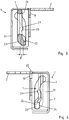
- Figure 5 shows that the curved links 11 are each composed of a largely vertical lower leg 12, a curved upper leg 13 and a circular segment-shaped widening 14 adjoining the curved leg 13.
- a rear wall 18 also belongs to the housing 8.
- the rear wall 18 extends between the side walls 10 and is welded to them in a manner not shown in detail.
- a circular opening 19 is located inside the rear wall 18 to reduce weight.
- the rear wall 18 extends into the plane of the loading area 2 and has an upper side 20 which runs parallel to the loading area 2.
- the housing 8 is prefabricated, that is, the side walls 10 connected to one another via the rear wall 18 together with the bracket 7 are inserted into the opening 19 in the profile beam 3 and welded to it.
- Figure 1 shows the bracket 7 in the rest position.
- the bracket 7 has an oval eyelet 21, into which a hook of a lashing device (not shown in detail), such as a lashing chain, can be hung in the extended position.
- the bracket 7 has two diametrically opposite guide pins 21 at one end. Above the guide pins 22, the bracket 7 has bends 23, through which the bracket 7 is offset by a distance B from a central axis of the link 11 ( Figure 3 ).
- Figure 4 shows that the guide pins 22 have flattened areas 24, 25 arranged diametrically.
- the flattened areas 24, 25 are at a distance from one another so that the guide pins 22 can be displaced with slight play in the longitudinal direction of the slotted link 11, in the position shown in FIG Figure 4 and in the curved upper leg 13 of the link 11, however, cannot be pivoted at will. This is only possible around the axis A in the circular segment-shaped extension 14 at the upper end 16 ( Figures 6 and 8th ). Before inserting the lashing point 1 into the profile beam 3, this must also be done in the area of the widened section 15 ( Figure 5 ) possible, after insertion only to a limited extent.
- FIGS. 2 , 5 and 6 show the bracket 7 in a lashing position. It is pivoted in the direction of the loading area 2.
- the guide pin 22 is located in the circular segment-shaped extension 14 at the upper end 16.
- Figure 5 shows that the bracket 7 with its side 26 pivotable to the loading area 2 assumes an angle W of 30 ° with the loading area 2. This is the smallest attainable angle W.
- the angle W is determined by the size and position of a support cam 27 which rests on the upper side 20 of the rear wall 18.
- the support cam 27 is configured to be triangular in cross section.
- a support cam 27 is located on each leg of the bracket 7 or on both sides of the eyelet 21.
- the Figures 7 and 8 show the bracket 7 in a further position.
- the bracket 7 is pivoted outwards over the web 6 of the profile beam 3. It is in a horizontal position, but can be lowered a little further until it encounters a pivoting limiter 29.
- the pivot limit 29 is of the Opening 19 is formed in the profile beam 3.
- This pivot limitation 29 or lower edge of the opening 19 is located above the widened section 15 ( Figure 8 ). Above means closer to loading area 2.
- This pivot limitation 29 prevents the bracket 7, when it is located with its guide pin 22 in the area of the widened section 15, from being pivoted to such an extent that it can be removed from the two slotted links 11.
- the guide pins 22 do not have to have any thickenings at the ends. They are only prevented from being able to be removed from the side walls 10 by the pivot limiter 29.
- the guide pins 22 can therefore be made so short that they do not protrude beyond the outer sides of the housing 8 or the slotted links 11, but are essentially flush with the slotted guides 11 or the side walls 10.
Landscapes
- Engineering & Computer Science (AREA)
- Transportation (AREA)
- Mechanical Engineering (AREA)
- Fittings On The Vehicle Exterior For Carrying Loads, And Devices For Holding Or Mounting Articles (AREA)
Description
- Die Erfindung betrifft einen Zurrpunkt in einer Ladefläche gemäß den Merkmalen im Oberbegriff des Anspruchs 1.
- Zurrpunkte zählen zum Beispiel durch das deutsche Gebrauchsmuster
DE 20 2008 008 418 U1 zum Stand der Technik. Derartige Zurrpunkte besitzen eine Schwenkachse für einen Bügel, der aus einer Tasche herausgezogen und in eine Zurrstellung verlagert werden kann. Das Verzurren der Ladung auf der Ladefläche erfolgt unter Zugbelastung des Bügels, der selbsttätig eine Winkellage in Längsrichtung des Zurrmittels einnimmt. Hierbei sollte ein minimaler Winkel zur Ladefläche nicht unterschritten werden. Es ist bekannt, dass sich der Bügel an einer Rückwand des Zurrpunktes abstützen soll und nicht an Einrichtungen auf der Ladefläche, wie zum Beispiel Lichtgitter. Dadurch soll die Beschädigung der Ladefläche vermieden werden. Es ist vorgeschlagen worden, die Rückwand abzukröpfen, damit der abgewinkelte Bügel flächig an einer Oberseite der Rückwand zur Anlage kommt. Allerdings wird der Abstand zwischen der Schwenkachse und der Rückwand dadurch verkleinert. Bei einer Zugbelastung, die einem Winkel kleiner als dem minimal einstellbaren Winkel des Bügels entspricht, wird der Bügel im Kontaktbereich mit der Rückwand daher stark auf Biegung beansprucht, was zu unerwünschten Spannungsspitzen führen kann. - Aus der
NL 1 029 062 C2 US 3 904 154 A ,US 4 167 273 A undDE 10 2011 101 907 A1 bekannt. - Der Erfindung liegt die Aufgabe zugrunde, einen Zurrpunkt in oder an einer Ladefläche aufzuzeigen, welcher hinsichtlich der Spannungsspitzen im Bügel auch bei Kräften, die unterhalb des minimal einstellbaren Winkels angreifen optimiert ist.
- Diese Aufgabe ist bei einem Zurrpunkt mit den Merkmalen des Anspruchs 1 gelöst.
- Vorteilhafte Weiterbildungen der Erfindung sind Gegenstand der Unteransprüche.
- Die Erfindung betrifft einen Zurrpunkt für eine Ladefläche, insbesondere in einer oder an einer Ladefläche eines Transportfahrzeugs. Der Zurrpunkt umfasst einen Bügel mit seitlichen Führungszapfen. Die Führungszapfen sind um eine Achse unterhalb der Ladefläche und insbesondere parallel zur Ladefläche verschwenkbar. Die Führungszapfen sind dabei in Kulissen geführt. Dadurch ist der Bügel von einer Ruhestellung in eine Zurrstellung verschiebbar. In der Zurrstellung ragt er nach oben über die Ladefläche hinaus. In der Zurrstellung am oberen Ende der Kulissen ist der Bügel um die Achse verschwenkbar. Erfindungsgemäß ist vorgesehen, dass der Bügel an der in der Zurrstellung in Richtung zur Ladefläche verschwenkbaren Seite mindestens einen Stütznocken im Abstand von der Achse aufweist.
- Der Stütznocken ist eine Verdickung an der zur Ladefläche verschwenkbaren Seite. Diese Verdickung hat die Funktion in Kontakt mit einem Gegenlager zu gelangen. Das Gegenlager selbst kann Bestandteil der Ladefläche sein. Vorzugsweise handelt es sich bei dem Gegenlager um ein Bauteil des Zurrpunktes selbst. In der Zurrstellung wird der Bügel bei einer Zugrichtung, die kleiner ist als der kleinste erreichbare Winkel des Bügels, nach unten gegen die Ladefläche bzw. ein an der Ladefläche angeordnetes Auflager gestützt. Der Stütznocken ist so gestaltet, dass die an der Kontaktfläche mit dem Auflager entstehenden Kräfte möglichst gleichmäßig in den Bügel eingeleitet werden. Insbesondere ist der Stütznocken so gestaltet, dass es zu keiner Kerbwirkung im Bereich des Auflagers kommt.
- Der kleinste Winkel, der zwischen dem Bügel und der Ladefläche einzuschließen ist, wird von der Größe und Position des wenigstens einen Stütznockens bestimmt. Es wird als vorteilhaft angesehen, wenn der Stütznocken sich in einem möglichst großen Abstand von der Achse befindet, da der Abstand zwischen Stütznocken und Achse die Länge des Hebelarmes bestimmt und damit auch die Größe des in den Bügel eingebrachten Drehmoments. Die Größe des Stütznockens ist so zu verstehen, dass der Stütznocken eine gewisse Höhe hat. Die Höhe wird in Axialrichtung der von dem Bügel umgebenen Öse gemessen. Der Stütznocken sollte auch eine gewisse Breite an seiner Basis haben. Im Übergangsbereich zu dem Bügel ist der Stütznocken daher insbesondere breiter als an seinem freien Ende. Die Übergänge zwischen Stütznocken und Bügel sind vorzugsweise gerundet, so dass die Spannungen gleichmäßig von dem Stütznocken in den Bügel übertragen werden.
- Der Bügel ist vorzugsweise umfänglich geschlossen ausgebildet. Der Bügel besitzt einen linken und einen rechten Schenkel. Für eine gleichmäßige Abstützung kann vorzugsweise sowohl am linken als auch am rechten Schenkel jeweils ein Stütznocken angeordnet sein. Wenn es die geometrischen Verhältnisse zulassen, dass sich die Öse im Bügel komplett oberhalb der Ladefläche befindet, ist es auch möglich, den Stütznocken als durchgehende Leiste unterhalb der Öse auszugestalten. Wesentlich ist, dass der Zurrpunkt gleichmäßig belastet wird. Dies wird insbesondere durch Stütznocken erreicht, die weit voneinander entfernt sind, so dass eine möglichst großflächige, mehrfache Abstützung des Zurrpunkts gegeben ist.
- Der wenigstens eine Stütznocken soll zudem vorzugsweise eine Stützfläche aufweisen, die bei Erreichen des kleinsten Winkels parallel zu der Ladefläche angeordnet ist. Der Stütznocken kann zu diesem Zweck im Querschnitt zum Beispiel dreieckförmig konfiguriert sein, wobei die Basis dieses Dreiecks mit der verschwenkbaren Seite des Bügels verbunden ist. Eine Flanke bildet die Stützfläche. Die andere Flanke bleibt frei. Bei einem minimal einstellbaren Winkel von zum Beispiel 30° könnten die Flanken des im Querschnitt dreieckförmigen Stütznockens jeweils im Winkel von 30° zur Basis, das heißt, zur Seite des Bügels verlaufen. Der Bügel stützt sich dabei gewissermaßen horizontal, das heißt, in der Ebene der Ladefläche ab. Hierzu kann eine Oberseite einer Rückwand des Zurrpunktes dienen. Die Oberseite der Rückwand verläuft dabei vorzugsweise in der Ebene der Ladefläche. Die Rückwand muss - anders als im Stand der Technik - hierbei nicht mehr abgekröpft sein. Die Oberseite der Rückwand befindet sich dadurch in größerem Abstand von der Schwenkachse. Bei einer Zugbelastung unterhalb des kleinsten erreichbaren Winkels treten daher im Bereich des Stütznockens kleinere Biegemomente auf, als bei einer Abstützung, die näher an der Schwenkachse erfolgt.
- Der wenigstens eine Stütznocken hat ferner die Funktion, dass der Bügel noch besser gegen selbsttätiges Zurückrutschen in die Kulisse gesichert ist.
- Ein weiterer Vorteil ist, dass der Bediener visuell sicher feststellen kann, ob ein minimaler Winkel von zum Beispiel 30° beim Verzurren unterschritten wurde bzw. ob der Zurrpunkt überhaupt auf Biegung beansprucht wird.
- In vorteilhafter Weiterbildung der Erfindung ist vorgesehen, dass die Kulisse einen verbreiterten Abschnitt besitzt, zum Einsetzen der Führungszapfen in die Kulisse. Der verbreiterte Abschnitt ist in einem Abstand von einem oberen Ende und einem unteren Ende der Kulisse angeordnet. Bei der Erfindung ist vorgesehen, dass das Einsetzen der Führungszapfens in die Kulisse über den verbreiterten Abschnitt erfolgt.
- Die Kulisse ist primär zur Linearführung des Bügels von einer Ruhestellung in eine Zurrstellung vorgesehen. Ein Verschwenken um die Führungszapfen zwischen der Ruhestellung und der Zurrstellung erfolgt bevorzugt nur im Rahmen der Fertigungstoleranzen. Das heißt, dass die Führungszapfen nicht kreisrund sind. Kreisrunde Zapfen haben den Nachteil, dass der Zurrpunkt auch in der Ruhestellung um die Achse verschwenken kann. Dies kann zu Klappern des Zurrpunkts während der Fahrt eines Transportfahrzeugs führen. Die Führungszapfen besitzen daher diametral angeordnete Abflachungen zur Linearführung. Die Kulisse besitzt an ihrem oberen Ende eine kreisförmige Erweiterung, so dass die abgeflachten Führungszapfen dort um ihre gemeinsame Achse verschwenkbar sind und/oder am unteren Ende eine Verjüngung, so dass der Bügel in der Ruhestellung nicht verschwenken kann. In jedem Fall ist der Bügel in der Zurrstellung verschwenkbar.
- Es ist vorgesehen, dass die Rückwand mit Seitenwänden verbunden ist, in denen sich die Kulissen befinden. Es ist ferner vorgesehen, die Seitenwände und die Kulissen miteinander zu verschweißen, so dass ein C-förmiges Gehäuse entsteht. Dieses vorgefertigte Gehäuse ist noch nicht mit dem Bügel verbunden. Dies erfolgt erst kurz vor der Montage. Hierzu kann der Bügel mit seinen abgeflachten Führungszapfen in den verbreiterten Abschnitt der Kulisse eingesetzt werden. Das ist auch dann möglich, wenn die Seitenwände bereits einen festen Abstand zueinander haben und über die Rückwand miteinander verbunden sind.
- Die Führungszapfen besitzen keine endseitigen Verdickungen oder Anstauchungen. Sie besitzen einen über ihre Länge gleichbleibenden Querschnitt. Insbesondere stehen sie nicht mit ihren freien Enden nach außen über die Kulissen in den Seitenwänden vor.
- Um in der Einbaulage ein Herausgleiten der Führungszapfen aus der Kulisse zu verhindern, muss sichergestellt werden, dass es im Bereich des verbreiterten Abschnitts eine Schwenkbegrenzung gibt. Das bedeutet, dass der im Bereich des Abschnitts um die Achse verschwenkbare Bügel nur so viel Freiraum hat, dass er einerseits gegen die Rückwand verschwenkt werden kann, was keinesfalls ein Herausgleiten des Führungszapfens aus der Kulissenführung ermöglicht, und andererseits über die Schwenkbegrenzung, die der Rückwand gegenüberliegt, an dem Herausschwenken gehindert ist. In praktischer Anwendung befindet sich die Schwenkbegrenzung oberhalb des verbreiterten Abschnitts.
- Der Zurrpunkt ist vorzugsweise in einen Profilholm mit C-förmigem Querschnitt eingesetzt. Die offene Seite des C-förmigen Profilholms weist zur Ladefläche, wobei die Ladefläche mit einem der beiden Schenkel des C-förmigen Profilholms abschließt. In diesem C-förmigen Profilholm ist eine Öffnung angeordnet, die nach oben, das heißt, zur Ladefläche hin offen ist. In diese Tasche kann zur Montage das Gehäuse des Zurrpunkts, bestehend aus der Rückwand und den beiden Seitenwänden, mit dem eingehängten Bügel eingesetzt werden. Die Öffnung im Profilholm ist auch zur Seite des Profilholms, das heißt, von der Ladefläche weg so weit geöffnet, dass der Profilholm die Schwenkbegrenzung für den Bügel bildet. Die Seitenwände können nun leicht zugänglich von außen mit dem Profilholm verschweißt werden.
- Die Erfindung wird nachfolgend anhand eines in den Zeichnungen dargestellten Ausführungsbeispiels näher erläutert. Es zeigen:
- Figur 1
- in der Perspektive einen Längenabschnitt eines Profilholms seitlich einer Ladefläche mit einem darin integrierten Zurrpunkt in der Ruhestellung;
- Figur 2
- den Zurrpunkt der
Figur 1 in einer Zurrstellung; - Figur 3
- einen Querschnitt durch die Darstellung der
Figur 1 mit einer vertikalen Schnittebene; - Figur 4
- eine Darstellung des Zurrpunkts der
Figur 1 in Richtung des Pfeils IV ausFigur 1 ; - Figur 5
- einen vertikalen Querschnitt durch die Darstellung des Zurrpunkts der
Figur 2 in Blickrichtung des Pfeils V inFigur 2 ; - Figur 6
- eine Seitenansicht des Zurrpunkts in Blickrichtung des Pfeils VI in
Figur 6 ; - Figur 7
- den Zurrpunkt der
Figur 1 in einer weiteren Perspektive und - Figur 8
- den Zurrpunkt in der Position gemäß
Figur 7 aus Blickrichtung des Pfeils VIII inFigur 7 . - Die Figuren zeigen einen Zurrpunkt 1, der in einen eine umfangseitige Begrenzung einer Ladefläche 2 eines ansonsten nicht näher dargestellten Transportfahrzeugs bildenden Profilholm 3 eingesetzt ist. Der Profilholm 3 hat einen C-förmigen Querschnitt mit einem oberen Schenkel 4, und einem unteren Schenkel 5 sowie mit einen die beiden Schenkel 4, 5 verbindenden Steg 6. Der Profilholm 3 ist zur Ladefläche 2 hin offen ausgebildet.
- Der Zurrpunkt 1 umfasst einen Bügel 7, welcher in einem Gehäuse 8 schwenkbar gelagert sowie vertikal geführt verschiebbar ist. Vertikal bedeutet in diesem Zusammenhang senkrecht zur Ladefläche 2 und bezeichnet die Hochrichtung in den Figuren.
- Das Gehäuse 8 ist mittels Schweißung in einer nach oben offenen und teilweise zur Außenseite hin offenen Aussparung 9 des Profilsholms 3 fixiert. Die Aussparung 9 erstreckt sich im oberen Schenkel 4 des Profilholms 3 sowie über einen Teil der Höhe seines Stegs 6.
- Das Gehäuse 8 besitzt zwei quer zum Profilholm 3 ausgerichtete Seitenwände 10. In diesen Seitenwänden 10 befinden sich gekrümmte Kulissen 11.
Figur 5 zeigt, dass die gekrümmten Kulissen 11 sich jeweils aus einem weitgehend vertikalen unteren Schenkel 12, einem gekrümmten oberen Schenkel 13 sowie einer sich an den gekrümmten Schenkel 13 anschließenden kreisabschnittsförmigen Erweiterung 14 zusammensetzen. - Im unteren Schenkel 12 befindet sich ein verbreiterter Abschnitt 15, der im Abstand vom oberen Ende 16 und dem unteren Ende 17 an der Kulisse 11 angeordnet ist (
Figur 5 ). - Zum Gehäuse 8 gehört ferner eine Rückwand 18. Die Rückwand 18 erstreckt sich zwischen den Seitenwänden 10 und ist mit diesen in nicht näher dargestellter Weise verschweißt. Innerhalb der Rückwand 18 befindet sich zur Gewichtsreduzierung eine kreisrunde Öffnung 19. Die Rückwand 18 erstreckt sich bis in die Ebene der Ladefläche 2 und besitzt eine Oberseite 20, die parallel zur Ladefläche 2 verläuft.
- Das Gehäuse 8 wird vorgefertigt, das heißt, die miteinander über die Rückwand 18 verbundenen Seitenwänden 10 zusammen mit dem Bügel 7 werden in die Öffnung 19 in den Profilholm 3 eingesetzt und mit diesem verschweißt.
Figur 1 zeigt dabei den Bügel 7 in der Ruhestellung. - Der Bügel 7 besitzt eine ovale Öse 21, in die bei ausgefahrener Position ein Haken eines nicht näher dargestellten Zurrgeschirrs, wie beispielsweise eine Zurrkette, eingehängt werden kann. Der Bügel 7 besitzt an einem Ende zwei einander diametral abgewandte Führungszapfen 21. Oberhalb der Führungszapfen 22 besitzt der Bügel 7 Abkröpfungen 23, durch welche der Bügel 7 um einen Abstand B zu einer Mittelachse der Kulisse 11 versetzt ist (
Figur 3 ). -
Figur 4 zeigt, dass die Führungszapfen 22 diametral angeordnete Abflachungen 24, 25 besitzen. Die Abflachungen 24, 25 befinden sich in einem Abstand zueinander, so dass die Führungszapfen 22 mit leichtem Spiel in Längsrichtung der Kulissen 11 verschoben werden können, in der dargestellten Position gemäßFigur 4 und in dem gekrümmten oberen Schenkel 13 der Kulisse 11 jedoch nicht beliebig verschwenkt werden können. Das ist nur um die Achse A in der kreisabschnittsförmigen Erweiterung 14 am oberen Ende 16 möglich (Figuren 6 und8 ). Vor dem Einsetzen des Zurrpunkts 1 in den Profilholm 3 ist das auch im Bereich des verbreiterten Abschnitts 15 (Figur 5 ) möglich, nach dem Einsetzen nur noch begrenzt. - Die
Figuren 2 ,5 und 6 zeigen den Bügel 7 in einer Zurrposition. Er ist in Richtung zur Ladefläche 2 verschwenkt. Der Führungszapfen 22 befindet sich in der kreisabschnittsförmigen Erweiterung 14 am oberen Ende 16.Figur 5 zeigt, dass der Bügel 7 mit seiner der zur Ladefläche 2 verschwenkbaren Seite 26 einen Winkel W von 30° mit der Ladefläche 2 einnimmt. Dies ist der kleinste erreichbare Winkel W. Der Winkel W wird durch die Größe und Position eines Stütznockens 27 bestimmt, der auf der Oberseite 20 der Rückwand 18 aufliegt. Der Stütznocken 27 ist im Querschnitt dreieckförmig konfiguriert. Je ein Stütznocken 27 befindet sich an jedem Schenkel des Bügels 7 bzw. beiderseits der Öse 21. Eine Stützfläche 28 des Stütznockens 27, die mit der Oberseite 20 der Rückwand 18 in Kontakt steht, ist abgeflacht und steht in einem Winkel W zur Seite 26 des Bügels 7 (Figur 3 ). Dadurch liegt der Stütznocken 27 flach auf der Oberseite 20 der Rückwand 18 auf. - Die
Figuren 7 und 8 zeigen den Bügel 7 in einer weiteren Position. Der Bügel 7 ist nach außen über den Steg 6 des Profilholms 3 geschwenkt. Er befindet sich in einer horizontalen Position, kann allerdings noch ein wenig weiter abgesenkt werden, bis er auf eine Schwenkbegrenzung 29 stößt. Die Schwenkbegrenzung 29 wird von der Öffnung 19 im Profilholm 3 gebildet. Diese Schwenkbegrenzung 29 bzw. Unterkante der Öffnung 19 befindet sich oberhalb des verbreiterten Abschnitts 15 (Figur 8 ). Oberhalb meint damit näher zur Ladefläche 2 hin. Diese Schwenkbegrenzung 29 verhindert, dass sich der Bügel 7, wenn er sich mit seinen Führungszapfen 22 im Bereich des verbreiterten Abschnitts 15 befindet, so weit verschwenkt werden kann, dass er aus den beiden Kulissen 11 entnommen werden kann. - Ein Vorteil dieser Anordnung ist, dass die Führungszapfen 22 keine endseitigen Verdickungen aufweisen müssen. Sie werden einzig durch die Schwenkbegrenzung 29 daran gehindert, aus den Seitenwänden 10 entnommen werden zu können. Die Führungszapfen 22 können daher so kurz gestaltet sein, dass sie nicht über die Außenseiten des Gehäuses 8 bzw. die Kulissen 11 vorstehen, sondern im Wesentlichen bündig mit den Kulissen 11 bzw. den Seitenwänden 10 abschließen.
-
- 1 -
- Zurrpunkt
- 2 -
- Ladefläche
- 3 -
- Profil holm
- 4 -
- oberer Schenkel von 3
- 5 -
- unterer Schenkel von 3
- 6 -
- Steg von 3
- 7 -
- Bügel
- 8 -
- Gehäuse
- 9 -
- Aussparung in 3
- 10 -
- Seitenwände von 8
- 11 -
- Kulissen in 10
- 12 -
- vertikaler Schenkel von 11
- 13 -
- gekrümmter Schenkel von 11
- 14 -
- Erweiterung von 11
- 15 -
- verbreiterter Abschnitt in 11
- 16 -
- oberes Ende von 11
- 17 -
- unteres Ende von 11
- 18 -
- Rückwand von 8
- 19 -
- Öffnung
- 20 -
- Oberseite von 18
- 21 -
- Öse
- 22 -
- Führungszapfen
- 23 -
- Abkröpfung
- 24 -
- Abflachung an 22
- 25 -
- Abflachung an 22
- 26 -
- Seite von 7
- 27 -
- Stütznocken
- 28 -
- Stützfläche von 27
- 29 -
- Schwenkbegrenzung
- A -
- Achse
- B -
- Abstand
- W -
- Winkel
Claims (10)
- Zurrpunkt in oder an einer Ladefläche, der einen Bügel (7) mit seitlichen Führungszapfen (22) aufweist, die um eine Achse (A) unterhalb zur Ladefläche (2) verschwenkbar und in Kulissen (11) geführt sind, so dass der Bügel (7) von einer Ruhestellung in eine Zurrstellung verschiebbar ist und in der Zurrstellung nach oben über die Ladefläche (2) ragt und in der Zurrstellung in Richtung zur Ladefläche (2) um die Achse (A) verschwenkbar ist, dadurch gekennzeichnet, dass der Bügel (7) an seiner in der Zurrstellung in Richtung zu Ladefläche (2) verschwenkbaren Seite (26) mindestens einen Stütznocken (27) im Abstand von der Achse (A) aufweist.
- Zurrpunkt nach Anspruch 1, dadurch gekennzeichnet, dass ein kleinster Winkel (W), der zwischen dem Bügel (7) und der Ladefläche (2) einzuschließen ist von der Größe und Position des wenigstens einen Stütznockens (27) bestimmt ist.
- Zurrpunkt nach Anspruch 1 oder 2, dadurch gekennzeichnet, dass der Bügel (7) an seiner zur Ladefläche (2) verschwenkbaren Seite (26) zwei Stütznocken (27) aufweist.
- Zurrpunkt nach Anspruch 2 oder 3, dadurch gekennzeichnet, dass der wenigstens eine Stütznocken (27) eine Stützfläche (28) aufweist, die bei Erreichen des kleinsten Winkels (W) parallel zu Ladefläche (2) angeordnet ist.
- Zurrpunkt nach einem der Ansprüche 1 bis 4, dadurch gekennzeichnet, dass der wenigstens eine Stütznocken (27) bei Erreichen des kleinsten Winkels (W) an einer Oberseite (20) einer Rückwand (18) des Zurrpunktes (1) abgestützt ist.
- Zurrpunkt nach Anspruch 5, dadurch gekennzeichnet, dass die Oberseite (20) der Rückwand (18) in der Ladefläche (2) angeordnet ist.
- Zurrpunkt nach einem der Ansprüche 1 bis 6, dadurch gekennzeichnet, dass die Kulisse (11) einen verbreiterten Abschnitt (15) besitzt, zum Einsetzen der Führungszapfen (22) in die Kulisse (11), wobei der verbreiterte Abschnitt (15) in einem Abstand von einem oberen Ende (16) und einem unteren Ende (17) der Kulisse (11) angeordnet ist.
- Zurrpunkt nach Anspruch 7, dadurch gekennzeichnet, dass die Rückwand (18) mit Seitenwänden (10) verbunden ist, in denen sich die Kulissen (11) befinden und ein C-förmiges Gehäuse (8) bilden, wobei die der Rückwand (18) gegenüberliegende Seite des Gehäuses (8) in der Einbaulage des Gehäuses (8) an der Ladefläche (2) eine Schwenkbegrenzung (29) aufweist, die sich oberhalb des verbreiterten Abschnittes (15) befindet.
- Zurrpunkt nach einem der Ansprüche 1 bis 8, dadurch gekennzeichnet, dass die Führungszapfen (22) über ihre Länge einen gleichbleibenden Querschnitt besitzen.
- Zurrpunkt nach einem der Ansprüche 1 bis 9, dadurch gekennzeichnet, dass die Kulissen (11) an ihren oberen Enden (16) kreisförmig erweitert sind, wobei die Führungszapfen (22) diametral angeordnete Abflachungen (24, 25) besitzen, deren Abstand (B) eine lineare Verlagerung in den Kulissen (11) ermöglicht und in der Einbaulage nur in der Zurrstellung am oberen Ende (16) der Kulissen (11) ein Verschwenken um die Achse (A) ermöglichen.
Priority Applications (1)
| Application Number | Priority Date | Filing Date | Title |
|---|---|---|---|
| PL19170656T PL3539822T3 (pl) | 2015-02-17 | 2016-02-17 | Punkt mocowania |
Applications Claiming Priority (2)
| Application Number | Priority Date | Filing Date | Title |
|---|---|---|---|
| DE201520100750 DE202015100750U1 (de) | 2015-02-17 | 2015-02-17 | Zurrpunkt |
| EP16156145.1A EP3059119B1 (de) | 2015-02-17 | 2016-02-17 | Zurrpunkt |
Related Parent Applications (1)
| Application Number | Title | Priority Date | Filing Date |
|---|---|---|---|
| EP16156145.1A Division EP3059119B1 (de) | 2015-02-17 | 2016-02-17 | Zurrpunkt |
Publications (2)
| Publication Number | Publication Date |
|---|---|
| EP3539822A1 EP3539822A1 (de) | 2019-09-18 |
| EP3539822B1 true EP3539822B1 (de) | 2021-01-06 |
Family
ID=52693739
Family Applications (2)
| Application Number | Title | Priority Date | Filing Date |
|---|---|---|---|
| EP19170656.3A Active EP3539822B1 (de) | 2015-02-17 | 2016-02-17 | Zurrpunkt |
| EP16156145.1A Active EP3059119B1 (de) | 2015-02-17 | 2016-02-17 | Zurrpunkt |
Family Applications After (1)
| Application Number | Title | Priority Date | Filing Date |
|---|---|---|---|
| EP16156145.1A Active EP3059119B1 (de) | 2015-02-17 | 2016-02-17 | Zurrpunkt |
Country Status (3)
| Country | Link |
|---|---|
| EP (2) | EP3539822B1 (de) |
| DE (1) | DE202015100750U1 (de) |
| PL (2) | PL3059119T3 (de) |
Families Citing this family (8)
| Publication number | Priority date | Publication date | Assignee | Title |
|---|---|---|---|---|
| DE102015211295B4 (de) * | 2015-06-18 | 2022-06-09 | Bos Gmbh & Co. Kg | Vorrichtung zum Sichern von Ladegut in einem Laderaum eines Kraftfahrzeugs |
| FR3058688B1 (fr) * | 2016-11-16 | 2018-12-07 | Pommier | Agencement d'arrimage d'objets sur une surface, notamment d'un plancher de chargement d'un vehicule de transport de cargaisons |
| DE202017101234U1 (de) | 2017-03-03 | 2018-06-05 | Thiele Gmbh & Co. Kg | Anschlagpunkt oder Zurrpunkt mit Magnet |
| FR3065411B1 (fr) * | 2017-04-24 | 2021-02-26 | Urben | Systeme d'arrimage d'une charge et support de plancher correspondant |
| DE202017104826U1 (de) * | 2017-08-10 | 2018-11-15 | Thiele Gmbh & Co. Kg | Zurrpunkt mit Magnetarretierung |
| DE202018102543U1 (de) * | 2018-05-07 | 2019-08-08 | Thiele Gmbh & Co. Kg | Zurrpunkt mit Montagestellung |
| DE202019101641U1 (de) | 2019-03-21 | 2020-06-23 | Thiele Gmbh & Co. Kg | Zurrpunkt mit Montagestellung |
| DE102020109274B3 (de) * | 2019-04-05 | 2020-08-13 | Thiele Gmbh & Co Kg | Zurröse mit Mittelstück zur Anordnung an einer Ladefläche eines Transportfahrzeuges |
Family Cites Families (10)
| Publication number | Priority date | Publication date | Assignee | Title |
|---|---|---|---|---|
| US3904154A (en) * | 1974-05-13 | 1975-09-09 | Us Navy | Securing system for jet engine testing of aircraft |
| CH612381A5 (de) * | 1976-12-08 | 1979-07-31 | Alusuisse | |
| US4360300A (en) | 1980-09-22 | 1982-11-23 | Illinois Railway Equipment Company | Self-resetting snubbing anchoring and releasing lading strapping on railway freight cars |
| DE3935267C2 (de) | 1989-10-24 | 1994-02-10 | Man Nutzfahrzeuge Ag | Zurrabstützung für die Ladebrücke eines Lkw |
| DE29500242U1 (de) | 1995-01-09 | 1996-05-09 | Plogmann, Kurt, 49082 Osnabrück | Verzurrhalterung an einem Lastkraftwagen |
| DE19841992C1 (de) | 1998-09-04 | 1999-10-28 | Rud Ketten Rieger & Dietz | Anschlußvorrichtung |
| NL1029061C2 (nl) * | 2005-05-17 | 2006-11-20 | Konink Nooteboom Trailers B V | Inrichting voor het bevestigen van lading op een laadvlak. |
| DE202006007916U1 (de) | 2006-05-17 | 2006-08-24 | Koninklijke Nooteboom Trailers B.V. | Vorrichtung zum Befestigen von Ladung auf einer Ladefläche |
| DE202008008418U1 (de) | 2008-06-13 | 2008-10-23 | Thiele Gmbh & Co. Kg | Zurrpunkt in einer Begrenzung einer Ladefläche eines Transportfahrzeugs |
| DE102011101907B4 (de) * | 2011-05-18 | 2021-10-28 | CIMC Silvergreen GmbH | Vorrichtung zur ladungssicherung |
-
2015
- 2015-02-17 DE DE201520100750 patent/DE202015100750U1/de not_active Expired - Lifetime
-
2016
- 2016-02-17 PL PL16156145T patent/PL3059119T3/pl unknown
- 2016-02-17 EP EP19170656.3A patent/EP3539822B1/de active Active
- 2016-02-17 PL PL19170656T patent/PL3539822T3/pl unknown
- 2016-02-17 EP EP16156145.1A patent/EP3059119B1/de active Active
Non-Patent Citations (1)
| Title |
|---|
| None * |
Also Published As
| Publication number | Publication date |
|---|---|
| EP3059119B1 (de) | 2019-05-01 |
| PL3059119T3 (pl) | 2019-09-30 |
| PL3539822T3 (pl) | 2021-07-05 |
| EP3059119A1 (de) | 2016-08-24 |
| EP3539822A1 (de) | 2019-09-18 |
| DE202015100750U1 (de) | 2015-03-03 |
Similar Documents
| Publication | Publication Date | Title |
|---|---|---|
| EP3539822B1 (de) | Zurrpunkt | |
| DE4314538C2 (de) | Überrollschutz-Vorrichtung für ein Kraftfahrzeug | |
| DE20101388U1 (de) | Zahnstange | |
| EP2686578B1 (de) | Vorrichtung zum anschlagen von kettengliedern | |
| DE102014102626B4 (de) | Kettenglied für eine Energieführungskette | |
| EP3691958B1 (de) | Kippvorrichtung für das fahrerhaus eines lastkraftwagens | |
| EP3106421B1 (de) | Teleskopstange | |
| DE102013009486B3 (de) | Baumständer | |
| EP3838669A1 (de) | Sperrbalken zur anordnung in einem laderaum eines fahrzeugs | |
| EP2807053B1 (de) | Vorrichtung zum bewegen von lasten innerhalb eines fahrzeugs, fahrzeug sowie verfahren zum bewegen von lasten innerhalb eines fahrzeugs | |
| DE4026157A1 (de) | Befestigungsvorrichtung | |
| DE102015117860A1 (de) | Schwenkbares Blockschloss | |
| DE202008008417U1 (de) | Verriegelung zum Verriegeln eines Containers auf einer Auflage | |
| EP2784222A1 (de) | Leitplankenvorrichtung, insbesondere Leitplankenüberleitungssystem, mit Verriegelungseinheit und Kurzabsenkung | |
| AT505880B1 (de) | Verbindungselement für eine gliederkette | |
| EP1580070A2 (de) | Maschine mit einer Hebeeinrichtung | |
| DE102016121013A1 (de) | Flachgliederkette | |
| EP2826365B1 (de) | Zaunelement | |
| DE102020109274B3 (de) | Zurröse mit Mittelstück zur Anordnung an einer Ladefläche eines Transportfahrzeuges | |
| DE202011052388U1 (de) | Markise | |
| DE102019114076B4 (de) | Schwenkvorrichtung für ein fahrzeug | |
| DE10343915B4 (de) | Kastenaufbau | |
| EP3495308A1 (de) | Containeraufhängevorrichtung | |
| CH714223A2 (de) | Steuerlitzenkupplung für Lamellenstoren. | |
| DE102022105030A1 (de) | Fahrzeug |
Legal Events
| Date | Code | Title | Description |
|---|---|---|---|
| PUAI | Public reference made under article 153(3) epc to a published international application that has entered the european phase |
Free format text: ORIGINAL CODE: 0009012 |
|
| STAA | Information on the status of an ep patent application or granted ep patent |
Free format text: STATUS: THE APPLICATION HAS BEEN PUBLISHED |
|
| AC | Divisional application: reference to earlier application |
Ref document number: 3059119 Country of ref document: EP Kind code of ref document: P |
|
| AK | Designated contracting states |
Kind code of ref document: A1 Designated state(s): AL AT BE BG CH CY CZ DE DK EE ES FI FR GB GR HR HU IE IS IT LI LT LU LV MC MK MT NL NO PL PT RO RS SE SI SK SM TR |
|
| STAA | Information on the status of an ep patent application or granted ep patent |
Free format text: STATUS: REQUEST FOR EXAMINATION WAS MADE |
|
| 17P | Request for examination filed |
Effective date: 20200311 |
|
| GRAP | Despatch of communication of intention to grant a patent |
Free format text: ORIGINAL CODE: EPIDOSNIGR1 |
|
| STAA | Information on the status of an ep patent application or granted ep patent |
Free format text: STATUS: GRANT OF PATENT IS INTENDED |
|
| INTG | Intention to grant announced |
Effective date: 20200608 |
|
| GRAJ | Information related to disapproval of communication of intention to grant by the applicant or resumption of examination proceedings by the epo deleted |
Free format text: ORIGINAL CODE: EPIDOSDIGR1 |
|
| STAA | Information on the status of an ep patent application or granted ep patent |
Free format text: STATUS: REQUEST FOR EXAMINATION WAS MADE |
|
| GRAS | Grant fee paid |
Free format text: ORIGINAL CODE: EPIDOSNIGR3 |
|
| STAA | Information on the status of an ep patent application or granted ep patent |
Free format text: STATUS: GRANT OF PATENT IS INTENDED |
|
| GRAP | Despatch of communication of intention to grant a patent |
Free format text: ORIGINAL CODE: EPIDOSNIGR1 |
|
| INTC | Intention to grant announced (deleted) | ||
| GRAA | (expected) grant |
Free format text: ORIGINAL CODE: 0009210 |
|
| STAA | Information on the status of an ep patent application or granted ep patent |
Free format text: STATUS: THE PATENT HAS BEEN GRANTED |
|
| INTG | Intention to grant announced |
Effective date: 20201119 |
|
| AC | Divisional application: reference to earlier application |
Ref document number: 3059119 Country of ref document: EP Kind code of ref document: P |
|
| AK | Designated contracting states |
Kind code of ref document: B1 Designated state(s): AL AT BE BG CH CY CZ DE DK EE ES FI FR GB GR HR HU IE IS IT LI LT LU LV MC MK MT NL NO PL PT RO RS SE SI SK SM TR |
|
| REG | Reference to a national code |
Ref country code: GB Ref legal event code: FG4D Free format text: NOT ENGLISH |
|
| REG | Reference to a national code |
Ref country code: AT Ref legal event code: REF Ref document number: 1352001 Country of ref document: AT Kind code of ref document: T Effective date: 20210115 Ref country code: CH Ref legal event code: EP |
|
| REG | Reference to a national code |
Ref country code: DE Ref legal event code: R096 Ref document number: 502016012166 Country of ref document: DE |
|
| REG | Reference to a national code |
Ref country code: IE Ref legal event code: FG4D Free format text: LANGUAGE OF EP DOCUMENT: GERMAN |
|
| REG | Reference to a national code |
Ref country code: NL Ref legal event code: FP |
|
| REG | Reference to a national code |
Ref country code: LT Ref legal event code: MG9D |
|
| PG25 | Lapsed in a contracting state [announced via postgrant information from national office to epo] |
Ref country code: PT Free format text: LAPSE BECAUSE OF FAILURE TO SUBMIT A TRANSLATION OF THE DESCRIPTION OR TO PAY THE FEE WITHIN THE PRESCRIBED TIME-LIMIT Effective date: 20210506 Ref country code: NO Free format text: LAPSE BECAUSE OF FAILURE TO SUBMIT A TRANSLATION OF THE DESCRIPTION OR TO PAY THE FEE WITHIN THE PRESCRIBED TIME-LIMIT Effective date: 20210406 Ref country code: LT Free format text: LAPSE BECAUSE OF FAILURE TO SUBMIT A TRANSLATION OF THE DESCRIPTION OR TO PAY THE FEE WITHIN THE PRESCRIBED TIME-LIMIT Effective date: 20210106 Ref country code: FI Free format text: LAPSE BECAUSE OF FAILURE TO SUBMIT A TRANSLATION OF THE DESCRIPTION OR TO PAY THE FEE WITHIN THE PRESCRIBED TIME-LIMIT Effective date: 20210106 Ref country code: HR Free format text: LAPSE BECAUSE OF FAILURE TO SUBMIT A TRANSLATION OF THE DESCRIPTION OR TO PAY THE FEE WITHIN THE PRESCRIBED TIME-LIMIT Effective date: 20210106 Ref country code: GR Free format text: LAPSE BECAUSE OF FAILURE TO SUBMIT A TRANSLATION OF THE DESCRIPTION OR TO PAY THE FEE WITHIN THE PRESCRIBED TIME-LIMIT Effective date: 20210407 Ref country code: BG Free format text: LAPSE BECAUSE OF FAILURE TO SUBMIT A TRANSLATION OF THE DESCRIPTION OR TO PAY THE FEE WITHIN THE PRESCRIBED TIME-LIMIT Effective date: 20210406 |
|
| PG25 | Lapsed in a contracting state [announced via postgrant information from national office to epo] |
Ref country code: SE Free format text: LAPSE BECAUSE OF FAILURE TO SUBMIT A TRANSLATION OF THE DESCRIPTION OR TO PAY THE FEE WITHIN THE PRESCRIBED TIME-LIMIT Effective date: 20210106 Ref country code: LV Free format text: LAPSE BECAUSE OF FAILURE TO SUBMIT A TRANSLATION OF THE DESCRIPTION OR TO PAY THE FEE WITHIN THE PRESCRIBED TIME-LIMIT Effective date: 20210106 Ref country code: RS Free format text: LAPSE BECAUSE OF FAILURE TO SUBMIT A TRANSLATION OF THE DESCRIPTION OR TO PAY THE FEE WITHIN THE PRESCRIBED TIME-LIMIT Effective date: 20210106 |
|
| PG25 | Lapsed in a contracting state [announced via postgrant information from national office to epo] |
Ref country code: IS Free format text: LAPSE BECAUSE OF FAILURE TO SUBMIT A TRANSLATION OF THE DESCRIPTION OR TO PAY THE FEE WITHIN THE PRESCRIBED TIME-LIMIT Effective date: 20210506 |
|
| REG | Reference to a national code |
Ref country code: DE Ref legal event code: R097 Ref document number: 502016012166 Country of ref document: DE |
|
| PG25 | Lapsed in a contracting state [announced via postgrant information from national office to epo] |
Ref country code: EE Free format text: LAPSE BECAUSE OF FAILURE TO SUBMIT A TRANSLATION OF THE DESCRIPTION OR TO PAY THE FEE WITHIN THE PRESCRIBED TIME-LIMIT Effective date: 20210106 Ref country code: CH Free format text: LAPSE BECAUSE OF NON-PAYMENT OF DUE FEES Effective date: 20210228 Ref country code: MC Free format text: LAPSE BECAUSE OF FAILURE TO SUBMIT A TRANSLATION OF THE DESCRIPTION OR TO PAY THE FEE WITHIN THE PRESCRIBED TIME-LIMIT Effective date: 20210106 Ref country code: LI Free format text: LAPSE BECAUSE OF NON-PAYMENT OF DUE FEES Effective date: 20210228 Ref country code: SM Free format text: LAPSE BECAUSE OF FAILURE TO SUBMIT A TRANSLATION OF THE DESCRIPTION OR TO PAY THE FEE WITHIN THE PRESCRIBED TIME-LIMIT Effective date: 20210106 |
|
| PLBE | No opposition filed within time limit |
Free format text: ORIGINAL CODE: 0009261 |
|
| STAA | Information on the status of an ep patent application or granted ep patent |
Free format text: STATUS: NO OPPOSITION FILED WITHIN TIME LIMIT |
|
| PG25 | Lapsed in a contracting state [announced via postgrant information from national office to epo] |
Ref country code: RO Free format text: LAPSE BECAUSE OF FAILURE TO SUBMIT A TRANSLATION OF THE DESCRIPTION OR TO PAY THE FEE WITHIN THE PRESCRIBED TIME-LIMIT Effective date: 20210106 Ref country code: SK Free format text: LAPSE BECAUSE OF FAILURE TO SUBMIT A TRANSLATION OF THE DESCRIPTION OR TO PAY THE FEE WITHIN THE PRESCRIBED TIME-LIMIT Effective date: 20210106 Ref country code: DK Free format text: LAPSE BECAUSE OF FAILURE TO SUBMIT A TRANSLATION OF THE DESCRIPTION OR TO PAY THE FEE WITHIN THE PRESCRIBED TIME-LIMIT Effective date: 20210106 |
|
| 26N | No opposition filed |
Effective date: 20211007 |
|
| PG25 | Lapsed in a contracting state [announced via postgrant information from national office to epo] |
Ref country code: AL Free format text: LAPSE BECAUSE OF FAILURE TO SUBMIT A TRANSLATION OF THE DESCRIPTION OR TO PAY THE FEE WITHIN THE PRESCRIBED TIME-LIMIT Effective date: 20210106 Ref country code: ES Free format text: LAPSE BECAUSE OF FAILURE TO SUBMIT A TRANSLATION OF THE DESCRIPTION OR TO PAY THE FEE WITHIN THE PRESCRIBED TIME-LIMIT Effective date: 20210106 |
|
| PG25 | Lapsed in a contracting state [announced via postgrant information from national office to epo] |
Ref country code: SI Free format text: LAPSE BECAUSE OF FAILURE TO SUBMIT A TRANSLATION OF THE DESCRIPTION OR TO PAY THE FEE WITHIN THE PRESCRIBED TIME-LIMIT Effective date: 20210106 |
|
| PG25 | Lapsed in a contracting state [announced via postgrant information from national office to epo] |
Ref country code: IS Free format text: LAPSE BECAUSE OF FAILURE TO SUBMIT A TRANSLATION OF THE DESCRIPTION OR TO PAY THE FEE WITHIN THE PRESCRIBED TIME-LIMIT Effective date: 20210506 |
|
| PG25 | Lapsed in a contracting state [announced via postgrant information from national office to epo] |
Ref country code: CY Free format text: LAPSE BECAUSE OF FAILURE TO SUBMIT A TRANSLATION OF THE DESCRIPTION OR TO PAY THE FEE WITHIN THE PRESCRIBED TIME-LIMIT Effective date: 20210106 |
|
| PG25 | Lapsed in a contracting state [announced via postgrant information from national office to epo] |
Ref country code: HU Free format text: LAPSE BECAUSE OF FAILURE TO SUBMIT A TRANSLATION OF THE DESCRIPTION OR TO PAY THE FEE WITHIN THE PRESCRIBED TIME-LIMIT; INVALID AB INITIO Effective date: 20160217 |
|
| PG25 | Lapsed in a contracting state [announced via postgrant information from national office to epo] |
Ref country code: MK Free format text: LAPSE BECAUSE OF FAILURE TO SUBMIT A TRANSLATION OF THE DESCRIPTION OR TO PAY THE FEE WITHIN THE PRESCRIBED TIME-LIMIT Effective date: 20210106 |
|
| PG25 | Lapsed in a contracting state [announced via postgrant information from national office to epo] |
Ref country code: MT Free format text: LAPSE BECAUSE OF FAILURE TO SUBMIT A TRANSLATION OF THE DESCRIPTION OR TO PAY THE FEE WITHIN THE PRESCRIBED TIME-LIMIT Effective date: 20210106 |
|
| PGFP | Annual fee paid to national office [announced via postgrant information from national office to epo] |
Ref country code: CZ Payment date: 20250212 Year of fee payment: 10 |
|
| PG25 | Lapsed in a contracting state [announced via postgrant information from national office to epo] |
Ref country code: TR Free format text: LAPSE BECAUSE OF FAILURE TO SUBMIT A TRANSLATION OF THE DESCRIPTION OR TO PAY THE FEE WITHIN THE PRESCRIBED TIME-LIMIT Effective date: 20210106 |
|
| PGFP | Annual fee paid to national office [announced via postgrant information from national office to epo] |
Ref country code: NL Payment date: 20260218 Year of fee payment: 11 Ref country code: LU Payment date: 20260218 Year of fee payment: 11 |
|
| PGFP | Annual fee paid to national office [announced via postgrant information from national office to epo] |
Ref country code: GB Payment date: 20260219 Year of fee payment: 11 |
|
| PGFP | Annual fee paid to national office [announced via postgrant information from national office to epo] |
Ref country code: DE Payment date: 20260224 Year of fee payment: 11 Ref country code: IE Payment date: 20260218 Year of fee payment: 11 |
|
| PGFP | Annual fee paid to national office [announced via postgrant information from national office to epo] |
Ref country code: AT Payment date: 20260219 Year of fee payment: 11 |
|
| PGFP | Annual fee paid to national office [announced via postgrant information from national office to epo] |
Ref country code: BE Payment date: 20260218 Year of fee payment: 11 Ref country code: IT Payment date: 20260224 Year of fee payment: 11 |
|
| PGFP | Annual fee paid to national office [announced via postgrant information from national office to epo] |
Ref country code: FR Payment date: 20260218 Year of fee payment: 11 |
|
| PGFP | Annual fee paid to national office [announced via postgrant information from national office to epo] |
Ref country code: PL Payment date: 20260206 Year of fee payment: 11 |