EP3539661A1 - Inkubationsrinne sowie inkubationswanne mit mehreren inkubationsrinnen - Google Patents
Inkubationsrinne sowie inkubationswanne mit mehreren inkubationsrinnen Download PDFInfo
- Publication number
- EP3539661A1 EP3539661A1 EP18161240.9A EP18161240A EP3539661A1 EP 3539661 A1 EP3539661 A1 EP 3539661A1 EP 18161240 A EP18161240 A EP 18161240A EP 3539661 A1 EP3539661 A1 EP 3539661A1
- Authority
- EP
- European Patent Office
- Prior art keywords
- incubation
- receiving area
- receiving
- width
- test strip
- Prior art date
- Legal status (The legal status is an assumption and is not a legal conclusion. Google has not performed a legal analysis and makes no representation as to the accuracy of the status listed.)
- Granted
Links
Images



Classifications
-
- B—PERFORMING OPERATIONS; TRANSPORTING
- B01—PHYSICAL OR CHEMICAL PROCESSES OR APPARATUS IN GENERAL
- B01L—CHEMICAL OR PHYSICAL LABORATORY APPARATUS FOR GENERAL USE
- B01L3/00—Containers or dishes for laboratory use, e.g. laboratory glassware; Droppers
-
- B—PERFORMING OPERATIONS; TRANSPORTING
- B01—PHYSICAL OR CHEMICAL PROCESSES OR APPARATUS IN GENERAL
- B01L—CHEMICAL OR PHYSICAL LABORATORY APPARATUS FOR GENERAL USE
- B01L3/00—Containers or dishes for laboratory use, e.g. laboratory glassware; Droppers
- B01L3/52—Containers specially adapted for storing or dispensing a reagent
-
- B—PERFORMING OPERATIONS; TRANSPORTING
- B01—PHYSICAL OR CHEMICAL PROCESSES OR APPARATUS IN GENERAL
- B01L—CHEMICAL OR PHYSICAL LABORATORY APPARATUS FOR GENERAL USE
- B01L3/00—Containers or dishes for laboratory use, e.g. laboratory glassware; Droppers
- B01L3/50—Containers for the purpose of retaining a material to be analysed, e.g. test tubes
-
- B—PERFORMING OPERATIONS; TRANSPORTING
- B01—PHYSICAL OR CHEMICAL PROCESSES OR APPARATUS IN GENERAL
- B01L—CHEMICAL OR PHYSICAL LABORATORY APPARATUS FOR GENERAL USE
- B01L3/00—Containers or dishes for laboratory use, e.g. laboratory glassware; Droppers
- B01L3/50—Containers for the purpose of retaining a material to be analysed, e.g. test tubes
- B01L3/508—Rigid containers without fluid transport within
- B01L3/5085—Rigid containers without fluid transport within for multiple samples, e.g. microtitration plates
- B01L3/50855—Rigid containers without fluid transport within for multiple samples, e.g. microtitration plates using modular assemblies of strips or of individual wells
-
- B—PERFORMING OPERATIONS; TRANSPORTING
- B01—PHYSICAL OR CHEMICAL PROCESSES OR APPARATUS IN GENERAL
- B01L—CHEMICAL OR PHYSICAL LABORATORY APPARATUS FOR GENERAL USE
- B01L9/00—Supporting devices; Holding devices
- B01L9/52—Supports specially adapted for flat sample carriers, e.g. for plates, slides, chips
-
- G—PHYSICS
- G01—MEASURING; TESTING
- G01N—INVESTIGATING OR ANALYSING MATERIALS BY DETERMINING THEIR CHEMICAL OR PHYSICAL PROPERTIES
- G01N33/00—Investigating or analysing materials by specific methods not covered by groups G01N1/00 - G01N31/00
- G01N33/48—Biological material, e.g. blood, urine; Haemocytometers
- G01N33/50—Chemical analysis of biological material, e.g. blood, urine; Testing involving biospecific ligand binding methods; Immunological testing
- G01N33/53—Immunoassay; Biospecific binding assay; Materials therefor
- G01N33/5302—Apparatus specially adapted for immunological test procedures
-
- G—PHYSICS
- G01—MEASURING; TESTING
- G01N—INVESTIGATING OR ANALYSING MATERIALS BY DETERMINING THEIR CHEMICAL OR PHYSICAL PROPERTIES
- G01N33/00—Investigating or analysing materials by specific methods not covered by groups G01N1/00 - G01N31/00
- G01N33/48—Biological material, e.g. blood, urine; Haemocytometers
- G01N33/50—Chemical analysis of biological material, e.g. blood, urine; Testing involving biospecific ligand binding methods; Immunological testing
- G01N33/53—Immunoassay; Biospecific binding assay; Materials therefor
- G01N33/543—Immunoassay; Biospecific binding assay; Materials therefor with an insoluble carrier for immobilising immunochemicals
- G01N33/54366—Apparatus specially adapted for solid-phase testing
-
- G—PHYSICS
- G01—MEASURING; TESTING
- G01N—INVESTIGATING OR ANALYSING MATERIALS BY DETERMINING THEIR CHEMICAL OR PHYSICAL PROPERTIES
- G01N33/00—Investigating or analysing materials by specific methods not covered by groups G01N1/00 - G01N31/00
- G01N33/48—Biological material, e.g. blood, urine; Haemocytometers
- G01N33/50—Chemical analysis of biological material, e.g. blood, urine; Testing involving biospecific ligand binding methods; Immunological testing
- G01N33/53—Immunoassay; Biospecific binding assay; Materials therefor
- G01N33/543—Immunoassay; Biospecific binding assay; Materials therefor with an insoluble carrier for immobilising immunochemicals
- G01N33/54366—Apparatus specially adapted for solid-phase testing
- G01N33/54386—Analytical elements
- G01N33/54387—Immunochromatographic test strips
-
- B—PERFORMING OPERATIONS; TRANSPORTING
- B01—PHYSICAL OR CHEMICAL PROCESSES OR APPARATUS IN GENERAL
- B01L—CHEMICAL OR PHYSICAL LABORATORY APPARATUS FOR GENERAL USE
- B01L2200/00—Solutions for specific problems relating to chemical or physical laboratory apparatus
- B01L2200/02—Adapting objects or devices to another
- B01L2200/026—Fluid interfacing between devices or objects, e.g. connectors, inlet details
-
- B—PERFORMING OPERATIONS; TRANSPORTING
- B01—PHYSICAL OR CHEMICAL PROCESSES OR APPARATUS IN GENERAL
- B01L—CHEMICAL OR PHYSICAL LABORATORY APPARATUS FOR GENERAL USE
- B01L2200/00—Solutions for specific problems relating to chemical or physical laboratory apparatus
- B01L2200/16—Reagents, handling or storing thereof
-
- B—PERFORMING OPERATIONS; TRANSPORTING
- B01—PHYSICAL OR CHEMICAL PROCESSES OR APPARATUS IN GENERAL
- B01L—CHEMICAL OR PHYSICAL LABORATORY APPARATUS FOR GENERAL USE
- B01L2300/00—Additional constructional details
- B01L2300/06—Auxiliary integrated devices, integrated components
- B01L2300/0627—Sensor or part of a sensor is integrated
- B01L2300/0663—Whole sensors
-
- B—PERFORMING OPERATIONS; TRANSPORTING
- B01—PHYSICAL OR CHEMICAL PROCESSES OR APPARATUS IN GENERAL
- B01L—CHEMICAL OR PHYSICAL LABORATORY APPARATUS FOR GENERAL USE
- B01L2300/00—Additional constructional details
- B01L2300/08—Geometry, shape and general structure
- B01L2300/0809—Geometry, shape and general structure rectangular shaped
- B01L2300/0825—Test strips
-
- B—PERFORMING OPERATIONS; TRANSPORTING
- B01—PHYSICAL OR CHEMICAL PROCESSES OR APPARATUS IN GENERAL
- B01L—CHEMICAL OR PHYSICAL LABORATORY APPARATUS FOR GENERAL USE
- B01L2300/00—Additional constructional details
- B01L2300/08—Geometry, shape and general structure
- B01L2300/0848—Specific forms of parts of containers
-
- G—PHYSICS
- G01—MEASURING; TESTING
- G01N—INVESTIGATING OR ANALYSING MATERIALS BY DETERMINING THEIR CHEMICAL OR PHYSICAL PROPERTIES
- G01N35/00—Automatic analysis not limited to methods or materials provided for in any single one of groups G01N1/00 - G01N33/00; Handling materials therefor
- G01N35/00029—Automatic analysis not limited to methods or materials provided for in any single one of groups G01N1/00 - G01N33/00; Handling materials therefor provided with flat sample substrates, e.g. slides
- G01N2035/00099—Characterised by type of test elements
- G01N2035/00108—Test strips, e.g. paper
-
- G—PHYSICS
- G01—MEASURING; TESTING
- G01N—INVESTIGATING OR ANALYSING MATERIALS BY DETERMINING THEIR CHEMICAL OR PHYSICAL PROPERTIES
- G01N35/00—Automatic analysis not limited to methods or materials provided for in any single one of groups G01N1/00 - G01N33/00; Handling materials therefor
- G01N2035/00346—Heating or cooling arrangements
- G01N2035/00356—Holding samples at elevated temperature (incubation)
Definitions
- the invention relates to an elongated incubation trough having a recess open to an upper side of the incubation trough and extending along a longitudinal direction of the incubation trough. Further, the incubation trough has a bottom which bounds the trough to a bottom of the incubation trough.
- the recess has a first receiving area for receiving an elongate test strip. In a preferred recording of the test strip in the first receiving area of the test strip is facing with its back to the ground and coated on its front with at least one analytical reagent.
- the recess further has a second receiving area, which is designed to receive an end portion of a fluid line, wherein the second receiving area is in fluid communication with the first receiving area. According to the invention, it is provided that a width of the first receiving area at ground level is greater than a width of the first receiving area at ground level.
- the disease may occur as a result of the formation of autoantibodies or the antibodies are formed in response to the disease, for example, in response to invasion of disease-causing viruses.
- exemplary diseases include infections, inflammatory diseases such as rheumatoid diseases, metabolic diseases such as diabetes and neurological diseases.
- test strips are also referred to as test strips, which are usually placed in incubation channels for incubation with liquid reagents, so that the test strip comes into contact with the reagent liquid in the incubation channel for a certain time.
- test strip usually has an elongated extent and a front and a back.
- the test strip is usually in the manner in the incubation channel that it rests with its back on the bottom of the incubation channel or the floor facing and that its front side faces the top of the Incubationsrinne.
- an analytical reagent on the front side or the test strip is coated on the front side with an analytical reagent.
- reagent liquid As part of a detection method of medical laboratory diagnostics using a previously mentioned test strip and an incubation trough more than one reagent liquid are usually used. After inserting the test strip into the incubation trough, a first reagent liquid is first introduced into the incubation trough and exposed to the test strip of this reagent liquid, after a certain time, which can be specified by the manufacturer of the test strip or test method to remove the reagent liquid again from the incubation trough is. In a further step, it may then be provided to introduce a further reagent liquid into the incubation trough in order to then expose the test strip to this further reagent liquid, it being possible to remove this reagent liquid from the incubation trough at even later time.
- the test strip can then be removed from the incubation channel in order to carry out a diagnosis or diagnosis by evaluating or viewing the test strip.
- diagnosis or diagnosis by evaluating or viewing the test strip.
- step diagnostics in which first a sensitive screening and then a specific confirmation are performed.
- ELISA enzyme-linked immunosorbent assay
- immuno-blot strips in particular western blot strips, dot blot strips or line blot strips, are used as confirmatory test.
- incubation troughs which can be used for various analytical and diagnostic test systems or tests.
- EP 3025780 A1 The applicant describes embodiments of incubation troughs in which it is intended, on the one hand, to connect a plurality of incubation troughs by means of mutually corresponding fastening means of the respective incubation troughs to form a composite of incubation troughs as an incubation trough.
- the object of the present invention is to allow for a reagent strip to be brought into a minimization of the reagent liquid to be used, in order to allow the user savings because reagents are sometimes expensive.
- the object of the invention is achieved by an elongated Incubationsrinne according to claim 1.
- the proposed elongate incubation trough has a recess open to an upper side of the incubation trough, which extends along a longitudinal direction of the incubation trough. Further, the incubation trough has a bottom which bounds the trough to a bottom of the incubation trough.
- the recess has a first receiving area for receiving an elongate test strip. In a preferred recording of the test strip in the first receiving area of the test strip is facing with its back to the ground and coated on its front with at least one analytical reagent.
- the recess further has a second receiving area, which is designed to receive an end portion of a fluid line, wherein the second receiving area is in fluid communication with the first receiving area. According to the invention, it is provided that a width of the first receiving area at ground level is greater than a width of the first receiving area at ground level.
- Such end portions of fluid lines for receiving a reagent liquid usually have a certain minimum width to ensure a minimum flow rate per unit time.
- the width of the end portion of the fluid line or the width of the second receiving area would determine the width for the first receiving area and thus a relevant Affect the volume of the first recording area. Since usually a certain minimum filling level of the first receiving area is necessary for adequate contacting of the test strip with reagent liquid, then the minimum width of the fluid line or the width of the second receiving area as the same width for the first receiving area would also have a significant influence on the amount to be used Have reagent liquid. In other words, the width of the second receiving area would determine the volume of the first receiving area and thus also the volume of reagent liquid to be used.
- the incubation troughs known from the state of the art are designed such that they have a substantially constant width, in particular at a floor level of the incubation trough. Therefore, it may occur in the prior art that the constant width provided there determines the total volume into which reagent liquid must be introduced to adequately cover the test strip. Usually, this requires a certain filling level of the incubation trough. Because the incubation channel according to the invention is set narrower in the first receiving area than in the second receiving area, the necessary filling height of the incubation channel results even with a smaller volume of reagent liquid than in the prior art, wherein it is still ensured that a conventional end portion a fluid line with a conventional dimensioning can be introduced into the second receiving area.
- the second receiving area may also be provided to receive an end portion of a fluid line for a processing step to introduce reagent liquid into the recess.
- a width of a receiving area preferably means a respective maximum width of a respective receiving area.
- the test strip faces the bottom when it is received in the first receiving area with its rear side and is also coated on its front side with at least one analytical reagent.
- the incubation trough is equipped with the test strip.
- the incubation channel is characterized in that the bottom along the first receiving area and along the second receiving area has a consistently constant ground level.
- the floor is formed along a two-dimensional ground plane, wherein further, a lateral boundary of the first receiving area along the longitudinal direction by two respective, mutually opposite longitudinal walls is formed, wherein at least one of the longitudinal walls in the manner obliquely to the ground plane, that the first receiving area narrowed from the top to the bottom.
- both of the longitudinal walls are inclined to the ground plane, so that there is a conical course of the cross section perpendicular to the longitudinal direction of the first receiving area from the top side to the ground plane.
- the second receiving region is located at an end region of the recess of the incubation trough.
- the second receiving area at the end region is delimited at the end by a transverse wall which extends from the bottom of the second receiving area upwards to the top and extends substantially transversely to the longitudinal direction of the incubation channel, wherein the transverse wall opposite the bottom of the second receiving area an obtuse angle greater than 90 °.
- the second receiving area In a transition from the second receiving area to the first receiving area, the second receiving area preferably has at least one rounding narrowing from the second receiving area to the first receiving area, preferably at ground level.
- the width of the second receiving area at ground level is preferably at least 4.5 mm and the width of the first receiving area at ground level is less than 3 mm.
- the first receiving area on its upper side has a width of at least 6 mm.
- two of the incubation troughs arranged parallel to one another each have a respective central axis or axis of symmetry in the longitudinal direction, wherein the respective central axes or symmetry axes have a spacing in the range from 8.5 mm to 9.5 mm.
- test strip means a preferably elongate carrier that is chemically sufficiently inert to conventional solvents, especially aqueous-based, and coated with a reagent suitable for a desired chemical reaction, in particular an analytical method, particularly preferably a laboratory diagnostic method, is suitable.
- the material of the test strip may be a membrane capable of taking up biological material or binding biological material.
- the test strip comprises or consists of nitrocellulose or polyvinylidene fluoride (PVDF).
- PVDF polyvinylidene fluoride
- To a test strip is preferably bound a biological material.
- the biological material is preferably selected from the group consisting of peptides / proteins, lipids, nucleic acids, saccharides, combinations and fusion molecules thereof.
- the biological material is a peptide / protein having a length of 2-500 amino acids (AS), 5- 450 AS, 10-400 AS, 20-350 AS, 30-300 AS, 50-250 AS, 80 - 200 AS, 100 - 150 AS or 115 - 135 AS.
- AS 2-500 amino acids
- the biological material is preferably applied as a discrete band on the test strip material, and the biological material preferably further has a content of at least 50, at least 60, at least 70, at least 80, at least 85, at least 90, at least 95, at least 97, at least 99 or 100% by weight based on the total weight and / or mole% based on the total composition of the band.
- the test strip material and the biological material may be a nitrocellulose strip having an antigen.
- the term "elongated” as used herein means that the aspect ratio of the longer to the shorter side in the order of increasing preference is at least 5: 1, 7.5: 1, 10: 1, 15: 1 or greater is.
- the term "coated" as used herein is understood to mean that the reagent is connected to the test strip in such a way that a liquid in contact with the front side of the strip also comes into contact with the reagent.
- the reagent may be blotted or dispensed or dispensed on the surface of the front panel, or the test strip may have a substantially uniform concentration of the reagent at each location. Suitable test strips are described in the prior art and are commercially available, for example line blots from the company EUROIMMUN Medical Laboratory Diagnostics AG, Lübeck.
- the term "analytical reagent" as used herein means a chemical compound that chemically or physically reacts with an analyte contained in a sample or other aqueous solution to be assayed. This reaction can be detected.
- the analytical reagent is an antigen, especially an epitope-containing polypeptide, to which an antibody to be detected, preferably autoantibodies, binds from a sample to be examined, whereupon the resulting antigen-antibody complex can be detected by means of a further, enzyme-conjugated antibody .
- the analytical reagent may be, for example, a pH-dependent dye that assumes a certain indicative color when exposed to a solution having a particular pH.
- the term "incubation trough” as used herein means a preferably liquid-tight container having a bottom, two longitudinal walls and two transverse walls.
- the incubation trough is elongated to accommodate a test strip can.
- the aspect ratio of the transverse wall to the longitudinal wall is at least 1: 5, 1:10 or greater.
- the incubation trough preferably consists of a material which is resistant to aqueous solutions, for example polystyrene, polyethylene or polypropylene.
- the incubation tray is equipped with a test strip and, optionally, contained in a package.
- test strip may preferably be a blot strip having reagents which may be suitable for detection of gangliosides, as disclosed in the patent application EP2952898 A1 known.
- a “test strip” may also preferably be a blot strip having reagents which may be suitable for detection of macadamia, as disclosed in the patent application EP3196209 A1 known.
- a “test strip” may further preferably be a blot strip having reagents which may become a blot strip Detection of Echinococcus may be suitable, as from the patent application EP EP3156798 known.
- a "test strip” may further preferably be a blot strip having reagents which may be suitable for detecting Ara h 7 isotype 7.0201, as disclosed in the patent application EP3244212 A1 known.
- the incubation trough contains a liquid next to the test strip.
- This can be a sample to be examined, a washing solution or a solution containing chemical reagents. Preservatives or analytes act.
- the incubation trough can be used purely manually by manually introducing and removing the required reagents for chemical reactions, especially analytical or diagnostic tests.
- the incubation trough or the composite is introduced into a device which carries out numerous, ideally all steps fully automatically, if possible without the presence of expert personnel being required.
- a device is equipped for storage, as well as for introducing and aspirating suitable buffers and reagents, ideally in addition to making suitable images of the fully processed test strip.
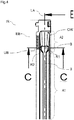
- FIG. 1a shows an incubation channel IR which extends longitudinally along a longitudinal axis LA.
- the incubation channel IR has a depression V, wherein the depression V in turn has a first receiving region A1 and a second receiving region A2.
- the first receiving area A1 is designed to receive an elongated test strip.
- the second receiving region A2 is designed to receive an end piece of a fluid line.
- the second receiving region A2 is preferably located in an end region EB of the incubation channel IR.
- the incubation channel IR can be pivoted about its transverse axis QA, which is perpendicular to the longitudinal axis LA, in order to effect an exchange of reagent liquid between the first receiving region A1 and the second receiving region A2. Furthermore, by a pivoting about the transverse axis QA, a distribution of reagent liquid in the first receiving area A1 can be effected in order to bring a test strip located in the first receiving area A1 completely into contact with reagent liquid.
- the FIG. 1b shows a first sectional view S1 of the Incubationsrinne along a section axis AA, as in the FIG. 1a located.
- the FIG. 1b in this case shows the depression V of the incubation channel IR in the region of the first receiving region A1.
- the depression V of the incubation channel IR is bounded by a bottom B towards the bottom US of the incubation channel IR.
- the Figure 1c shows a second step view S2 along the axis CC, as in FIG FIG. 1a located.
- the Figure 1c in this case shows the depression V of the incubation channel IR in the region of the second receiving region A2.
- the depression V of the incubation channel IR is also limited here by a bottom B to the underside US of the incubation channel IR.
- FIG. 2 shows the proposed Incubationsrinne IR in a side view in a section along the longitudinal axis LA and along the points EE of the FIG. 1a ,
- the first receiving region A1 in which preferably a test strip T is inserted, which is inserted with its rear side RS towards the lower side US or the bottom B of the incubation channel.
- the test strip T is coated on its front side VS with an analytical reagent.
- the test strip T is not necessarily part of the proposed incubation channel IR, but this may be preferred.
- the Indian FIG. 2 illustrated and preferably present test strip T is in the FIGS. 1a, b, c such as 3 to 8 not explicitly shown.
- the depression V is essentially formed by the first receiving region A1 into the second receiving region A2.
- the incubation channel IR is limited in the second receiving region A2 by a transverse wall QW end.
- FIG. 2 Further shown in FIG. 2 is a floor level BE, or ground level BH, along which the floor B extends.
- FIG. 3 shows the proposed Incubationsrinne IR again in an oblique view.
- FIG. 5 shows the sectional view S1 and thus a cross section of the first receiving area A1 and the recess V of the FIG. 1a along the axis AA.
- the width BR1 of the bottom B is the width which results for the recess or the first receiving area at ground level BH or ground level BE.
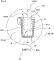
- FIG. 6 shows the sectional view S2 and thus a cross section of the first receiving area A2 and the recess V of the FIG. 1a along the axis CC.
- the width BR2 of the bottom B is the width which results for the recess or the first receiving area at ground level BH or ground level BE.
- FIG. 6 shows in dash-dot representation a fluid line FL, which is introduced with its end portion EA in the second receiving area A2, for example, to suck off reagent liquid or to introduce reagent liquid into the recess.
- FIG. 3 shows the bottom B, which according to the embodiment shown here, both in the region of the first receiving area A1 and the second receiving area A2 a consistently constant ground level BH, as in the Figures 5 and 6 drawn, has.
- a fluidic coupling between these two receiving areas A1, A2 is maximized, so that reagent liquid can be exchanged particularly easily between these two receiving areas A1, A2.
- transverse axis QA pivoted, so that the reagent liquid moves between the ends E1, E2 of the incubation channel IR back and forth. This is intended to achieve application of reagent liquid in a uniform manner to the surface of the test strip.
- the reagent liquid can go over particularly well from the second receiving area A2 in the first receiving area A1 and back again. If the reagent liquid is then sucked off at a later time in a later processing step by means of an end section of a fluid line which can be introduced into the second receiving region A2, the constant ground level also ensures that a maximum of reagent liquid from the depression V or the receiving areas A1, A2 can be removed. This ensures that only a minimum of reagent liquid remains in the incubation channel after such a suction step, before then preferably a new, further reagent liquid is introduced into the incubation channel or its second receiving region A2 for a further processing step.
- the bottom B extends along both receiving areas A1, A2 with a constant ground level on a common two-dimensional ground plane of the two receiving areas A1, A2 as a continuous area over these two receiving areas A1, A2.
- FIG. 5 In addition to the bottom B in the first receiving area further shows a lateral boundary of the first receiving area along the longitudinal direction by two respective, opposite longitudinal walls W1, W2. At least one of the longitudinal walls W1 extends obliquely in relation to the ground plane BE or to the ground B in such a way that the first receiving area A1 narrows from the upper side OS of the incubation channel IR or the first receiving area A1 to the underside US of the incubation channel IR.
- a width BA1 of the first receiving area A1 on the upper side OS is greater than the width BR1 of the first receiving area A1 on the ground B or at ground level BH.
- the first receiving region A1 narrows from the upper side OS toward the underside US or towards the bottom B, a test strip, which is only marginally narrower than the bottom of the first receiving region, can be inserted into the first receiving region A1 from the upper side OS be inserted more easily than if both longitudinal walls W1, W2 would be perpendicular to the ground plane BE and would form such a constant width of the first receiving area A1, which would be only marginally wider than the test tire at any height.
- such a constant width of the first receiving area A1 then would require a user to position the test strip for introduction into the first receiving area A1 very exactly at the level of the top OS with respect to a longitudinal direction, a transverse direction and / or rotation Align so that the test strip can then be correctly inserted into the first receiving area A1.
- the test strip can be inserted more easily by the user, since a tolerance compensation, a positioning of the test strip with respect to the first receiving area A1 is achieved.
- both longitudinal walls W1, W2 are inclined in relation to the ground plane BE, so that a conical course of the cross-section Q of the first receiving area A1 results from the upper side OS towards the ground plane BE or towards the bottom B.
- the cross-section Q is symmetrical to a central axis or surface normal FN, which is orthogonal to the ground plane BE.
- FIG. 1a further shows that the second receiving area A2 is located at an end region EB of the cavity V of the incubation trough. This end region EB as well as further details are more accurate at FIG. 4 shown.
- the FIG. 4 shows that the second receiving area A2 at the end region EB is delimited at the end by a transverse wall QW which extends from the bottom B of the second receiving area A2 upwards to the top of the second receiving area or the incubation channel IR.
- the transverse wall QW also extends substantially transversely to the longitudinal direction of the incubation channel IR.
- the transverse wall QW is also in the FIG. 3 marked as well as in the FIG. 2 , According to the FIG. 2 has, like the transverse wall QW with respect to the bottom B of the second receiving area A2 an obtuse angle QWI, which is greater than 90 °.
- reagent liquid is located in the incubation channel and if the incubation channel is rotated or tilted over its transverse axis towards the end region EB of the incubation channel IR at the end of a processing step, then in the second receiving region A2 the transverse wall QW or its profile proposed here can be used larger amount of reagent liquid are taken as if the transverse wall QW would be perpendicular to the bottom B and the bottom plane BE.
- the FIG. 4 further shows a transition area or a transition UB of the second receiving area A2, which borders on the first receiving area A1.
- the second receiving region A2 has respective narrowing curves R1, R2, preferably at the level or level of the bottom B.
- transition UB Due to such an embodiment of the transition UB, it is possible that despite different widths of the receiving areas A1, A2 at ground level or ground level a transition of reagent liquid from the second receiving area A2 to the first receiving area A1 is maximized. If, for example, an angular configuration of the transitional area UB between the receiving areas A1, A2 would be provided by rectangular corners in the transition area UB, then reagent liquid would flow less favorably from the second receiving area A2 to the first receiving area A1.
- corner areas proposed here with angles of 90 ° or less than 90 ° at the level of the bottom B or on the ground level BE is advantageous, since in such corner regions a reagent liquid could form greater adhesion forces due to surface tension than on round shaped edge areas, so that reagent liquid could remain in the second receiving area A2 and just could not pass into the first transition area A1. This would result in an inhomogeneous distribution of reagent liquid in the well and thus also in the receiving areas A1, A2 during a processing step, so that a homogeneous or even coverage of the test strip with reagent liquid could possibly not be achieved.
- the in the FIG. 6 drawn width BR2 of the second receiving area A2 is preferably at least 4.5 mm, preferably at least 5 mm, more preferably at least 5.5 mm.
- This width BR2 of the second receiving area A2 can also be referred to as the maximum width of the second receiving area A2.
- the in the FIG. 5 drawn width BR1 of the first receiving area A1 at ground level is preferably less than 3 mm, preferably less than 2.75 mm, more preferably less than 2.6 mm, preferably less than 2.5 mm.
- the longitudinal walls W1, W2 have a different height.
- these walls W1, W2 may have the same height.
- a first top side OS of the first receiving area A1 would result.
- a further upper side OS1 of the first receiving area could be defined, as in FIG FIG. 5 located.
- the first top OS is in the FIG. 5 a width BA1 of the first receiving area A1 drawn.
- a corresponding width of the first receiving area can be determined for the upper side OS1 shown there.
- OS1 has a width BA1 of at least 6 mm, preferably at least 6.5 mm.
- the FIG. 5 shows an opening angle WO1, which is given by an angular position of the two longitudinal walls W1, W2.
- This opening angle WO1 is the opening angle of the recess V in the first receiving area A1.
- This opening angle is preferably 21 °.
- the longitudinal wall W1 preferably has an angle WW1 of at least 7 °, preferably at least 8 °, more preferably at least 10 °, with respect to a surface normal FN of the ground plane BE or of the ground B.
- the angle WW1 of the longitudinal wall W1 does not exceed the value of 20 °, preferably 15 °, with respect to the surface normal FN of the ground plane BE or of the bottom B.
- the same can be provided for the other longitudinal wall W2. In this way it can be achieved that in the context of a camera evaluation or automated image analysis of the test strip by means of a view of the Incubationsrinne from above, as in the FIG. 1a can be performed without too great a degree of obstructive image artifacts.
- Such an image evaluation is usually carried out with the aid of illumination light, which shines from above into the incubation channel, so that a reflection of the illumination light on the insides of the longitudinal walls W1, W2 back to the camera is minimized by the angle WW1 having a certain value does not exceed. If a certain angle value were exceeded by the angle WW1, then automated image analysis could be made more difficult by such reflection effects on the walls W1, W2. If the longitudinal walls W1, W2 exceed the angle values proposed here, then such a reflection effect could be present to an excessive extent and an automated image analysis can be made more difficult.
- the Indian FIG. 2 drawn angles QWI which the transverse wall QW has with respect to the bottom B of the second receiving area A2, is preferably an angle in the range of 110 ° to 150 °, preferably 120 ° to 140 °, more preferably 125 ° to 135 °.
- the incubation trough proposed here is preferably produced by means of a plastic injection molding process. Due to the here selected dimensioning of width values and / or angle values proposed here, it is possible to replace the proposed incubation channel when manufactured by injection molding of an injection mold without significant mechanical resistance.
- a system with an incubation trough proposed here and also with a test strip described here is also proposed to use a here proposed system for the detection of biological material, preferably by inserting a test strip described here in an incubation trough proposed here, introducing at least one reagent liquid into the incubation trough for incubating the test strip, removing or sucking the reagent liquid from the incubation trough , Washing the test strip with at least one liquid wash buffer and detecting formation of at least one band on the test strip for detection of a biological material.
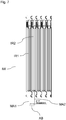
- FIG. 7 shows a proposed incubation tub IW with several incubation channels IR1, IR2, which are preferably arranged parallel to each other.
- the respective incubation channels IR1, IR2 have mutually corresponding fastening elements in order to obtain the incubation tub IW by joining the incubation channels IR1, IR2 together.
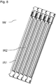
- FIG. 8 shows the proposed incubation tray with the mutually parallel incubation channels IR1, IR2 from an oblique view.
Landscapes
- Health & Medical Sciences (AREA)
- Immunology (AREA)
- Life Sciences & Earth Sciences (AREA)
- Chemical & Material Sciences (AREA)
- Engineering & Computer Science (AREA)
- Hematology (AREA)
- Molecular Biology (AREA)
- Biomedical Technology (AREA)
- Urology & Nephrology (AREA)
- General Health & Medical Sciences (AREA)
- Analytical Chemistry (AREA)
- Chemical Kinetics & Catalysis (AREA)
- Clinical Laboratory Science (AREA)
- Medicinal Chemistry (AREA)
- Biotechnology (AREA)
- Microbiology (AREA)
- Cell Biology (AREA)
- Food Science & Technology (AREA)
- Physics & Mathematics (AREA)
- Biochemistry (AREA)
- General Physics & Mathematics (AREA)
- Pathology (AREA)
- Apparatus Associated With Microorganisms And Enzymes (AREA)
- Automatic Analysis And Handling Materials Therefor (AREA)
Abstract
Description
- Die Erfindung betrifft eine längliche Inkubationsrinne, welche eine zu einer Oberseite der Inkubationsrinne hin offene Vertiefung aufweist, welche sich entlang einer Längsrichtung der Inkubationsrinne erstreckt. Ferner weist die Inkubationsrinne einen Boden auf, welcher die Vertiefung zu einer Unterseite der Inkubationsrinne hin begrenzt. Die Vertiefung weist einen ersten Aufnahmebereich zur Aufnahme eines länglichen Teststreifens auf. Bei einer bevorzugten Aufnahme des Teststreifens in den ersten Aufnahmebereiches ist der Teststreifen mit seiner Rückseite dem Boden zugewandt und auf seiner Vorderseite mit wenigstens einem analytischen Reagenz beschichtet. Erfindungsgemäß weist die Vertiefung ferner einen zweiten Aufnahmebereich auf, welcher zur Aufnahme eines Endabschnittes einer Fluidleitung ausgebildet ist, wobei der zweite Aufnahmebereich mit dem ersten Aufnahmebereich fluidisch in Verbindung steht. Erfindungsgemäß ist es vorgesehen, dass eine Breite des ersten Aufnahmebereiches auf Bodenhöhe größer ist als eine Breite des ersten Aufnahmebereichs auf Bodenhöhe.
- Auf dem Gebiet der medizinischen Labordiagnostik sind unterschiedliche Testsysteme bekannt, mit denen Patientenproben auf das Vorhandensein spezifischer Antikörper untersucht werden können. Durch solche Nachweise ist es möglich, Rückschlüsse auf das Auftreten von Krankheiten zu ziehen, die zusammen mit derartigen spezifischen Antikörpern auftreten. Die Krankheit kann als Folge der Bildung von Autoantikörpern auftreten oder die Antikörper werden als Reaktion auf die Krankheit gebildet, beispielsweise als Reaktion auf das Eindringen von krankheitserregenden Viren. Beispielhafte Krankheiten umfassen Infektionen, entzündliche Krankheiten wie rheumatoide Krankheiten, Stoffwechselkrankheiten wie Diabetes und neurologische Erkrankungen.
- Derartige Streifen werden auch als Teststreifen bezeichnet, welche zur Inkubation mit flüssigen Reagenzien üblicherweise in Inkubationsrinnen eingelegt werden, so dass der Teststreifen in der Inkubationsrinne für eine gewisse Zeit mit der Reagenzienflüssigkeit in Kontakt kommt.
- Ein solcher Teststreifen hat üblicherweise eine längliche Ausdehnung sowie eine Vorderseite und eine Rückseite. Der Teststreifen liegt üblicherweise in der Art in der Inkubationsrinne, dass er mit seiner Rückseite auf dem Boden der Inkubationsrinne aufliegt bzw. dem Boden zugewandt ist und dass seine Vorderseite der Oberseite der Inkubationsrinne zugewandt ist. Üblicherweise befindet sich auf der Vorderseite ein analytisches Reagenz bzw. der Teststreifen ist auf der Vorderseite mit einem analytischen Reagenz beschichtet.
- Im Rahmen eines Nachweisverfahrens der medizinischen Labordiagnostik unter Verwendung eines zuvor genannten Teststreifens sowie einer Inkubationsrinne werden üblicherweise mehr als eine Reagenzienflüssigkeit verwendet. Nach Einlegen des Teststreifens in die Inkubationsrinne wird zunächst eine erste Reagenzflüssigkeit in die Inkubationsrinne eingebracht und der Teststreifen dieser Reagenzienflüssigkeit ausgesetzt, wobei nach einer gewissen Zeit, welche durch den Hersteller des Teststreifens bzw. Testverfahrens vorgegeben werden kann, die Reagenzienflüssigkeit wieder aus der Inkubationsrinne zu entfernen ist. In einem weiteren Schritt kann dann vorgesehen sein, eine weitere Reagenzienflüssigkeit in die Inkubationsrinne einzubringen, um den Teststreifen dann dieser weiteren Reagenzflüssigkeit auszusetzen, wobei zu einem noch späteren Zeitpunkt es vorgesehen sein kann, auch diese Reagenzienflüssigkeit wieder aus der Inkubationsrinne zu entfernen.
Nach Durchführung derartiger Prozessierungsschritte kann der Teststreifen dann aus der Inkubationsrinne entnommen werden, um mittels Auswertung bzw. Betrachtung des Teststreifens eine Befundung bzw. Diagnose durchzuführen. Üblicherweise erfolgt der Nachweis von diagnostisch relevanten Antikörpern im Wege einer sogenannten Stufendiagnostik, bei der zunächst ein empfindliches Screening und dann eine spezifische Bestätigung durchgeführt werden. In der Routineserologie werden hierbei für das Screening oftmals ELISA (Enzyme-linked immunosorbent assay) verwendet, während als Bestätigungstest vornehmlich Immuno-Blotstreifen, insbesonderer Westernblot-Streifen, Dot Blot-Streifen oder Linienblot- Streifen eingesetzt werden. - Da der Bedarf an derartigen Testsystemen erheblich ist und die zum Einsatz kommenden Reagenzien oft hochpreisig, schwer zu beschaffen und nur in geringen Mengen verfügbar sind, ist eine Vereinfachung und Optimierung der Abläufe bei der Durchführung des jeweiligen Tests unerlässlich. Insbesondere müssen die verwendeten analytisch-diagnostischen Gerätschaften die möglichst störungsfreie und einfache parallele Durchführung zahlreicher Tests im Hochdurchsatzmaßstab ermöglichen. Jede Vereinfachung von Verfahrens-, Wartungs- oder Reinigungsschritten, jeder Ausschluß von noch so geringen Gefahrenquellen und jede Minimierung der Mengen der einzusetzenden Reagenzien führt für den Anwender zu erheblichen Einsparungen.
- Im Stand der Technik ist eine Reihe von Inkubationsrinnen beschrieben, welche für verschiedene analytische und diagnostische Testsysteme bzw. Tests eingesetzt werden können.
In der PatentanmeldungEP 3025780 A1 der Anmelderin sind Ausführungsformen von Inkubationsrinnen beschrieben, bei welchen es zum einen vorgesehen ist, mehrere Inkubationsrinnen mittels zueinander korrespondierender Befestigungsmittel der jeweiligen Inkubationsrinnen zu einem Verbund von Inkubationsrinnen als eine Inkubationswanne zusammenzuschließen. - Ferner ist es aus der Patentanmeldung
EP 3025779 A1 der Anmelderin bekannt, dass zur Fixierung bzw. Positionierung des Teststreifens im Bodenbereich der Inkubationsrinne Halteelemente in Form von aus Wänden der Inkubationsrinne hervorstehender Vorsprünge vorgesehen sein können. - Aufgabe der vorliegenden Erfindung ist es, für ein Zusammenbringen eines Teststreifens mit Reagenzienflüssigkeit in eine Minimierung der einzusetzenden Reagenzienflüssigkeit zu ermöglichen, um dem Anwender Einsparungen zu ermöglichen, da Reagenzien mitunter hochpreisig sind.
- Die erfindungsgemäße Aufgabe wird gelöst durch eine längliche Inkubationsrinne nach dem Patentanspruch 1.
- Die vorgeschlagene längliche Inkubationsrinne weist eine zu einer Oberseite der Inkubationsrinne hin offene Vertiefung auf, welche sich entlang einer Längsrichtung der Inkubationsrinne erstreckt. Ferner weist die Inkubationsrinne einen Boden auf, welcher die Vertiefung zu einer Unterseite der Inkubationsrinne hin begrenzt. Die Vertiefung weist einen ersten Aufnahmebereich zur Aufnahme eines länglichen Teststreifens auf. Bei einer bevorzugten Aufnahme des Teststreifens in den ersten Aufnahmebereiches ist der Teststreifen mit seiner Rückseite dem Boden zugewandt und auf seiner Vorderseite mit wenigstens einem analytischen Reagenz beschichtet. Erfindungsgemäß weist die Vertiefung ferner einen zweiten Aufnahmebereich auf, welcher zur Aufnahme eines Endabschnittes einer Fluidleitung ausgebildet ist, wobei der zweite Aufnahmebereich mit dem ersten Aufnahmebereich fluidisch in Verbindung steht. Erfindungsgemäß ist es vorgesehen, dass eine Breite des ersten Aufnahmebereiches auf Bodenhöhe größer ist als eine Breite des ersten Aufnahmebereichs auf Bodenhöhe.
- Um einen oder mehrere mögliche Vorteile der Erfindung zu erfassen, wird die Funktionsweise der vorgeschlagenen Inkubationsrinne im Folgenden zunächst näher erläutert.
- Wie zuvor erwähnt ist es üblich, dass nach Einbringen einer Reagenzienflüssigkeit in die Inkubationsrinne, um den Teststreifen dieser Reagenzien Flüssigkeit auszusetzen, es nach einem gewissen Zeitraum notwendig ist, diese Reagenzienflüssigkeit auch wieder aus der Inkubationsrinne zu entfernen, beispielsweise um eine Reaktion zwischen der Reagenzienflüssigkeit und einem auf der Vorderseite des Teststreifens befindlichen analytischen Reagenz anzuhalten. Hierzu kann es vorgesehen sein, mittels einer Fluidleitung eines Automaten oder aber einer Pipette einen Endabschnitt einer solchen Fluidleitung in den zweiten Aufnahmebereichs einzubringen, um dann die Reagenzienflüssigkeit bzw. einen größeren Teil der Reagenzienflüssigkeit aus der Vertiefung der Inkubationsrinne abzusaugen. Derartige Endabschnitte von Fluidleitungen zur Aufnahme einer Reagenzienflüssigkeit weisen meistens eine gewisse Mindestbreite zur Gewährleistung einer mindesten Flussmenge pro Zeiteinheit auf. Hätten der erste und der zweite Aufnahmebereich eine gemeinsame gleiche Breite, welche sich ausschließlich an der Mindestbreite der Fluidleitung orientieren würde, so würde die Breite des Endabschnittes der Fluidleitung bzw. die Breite des zweiten Aufnahmebereiches die Breite auch für den ersten Aufnahmebereich bestimmen und somit einen maßgeblichen Einfluss auf das Volumen des ersten Aufnahmebereiches haben. Da üblicherweise eine gewisse Mindestfüllhöhe des ersten Aufnahmebereiches für eine ausreichende Kontaktierung des Teststreifens mit Reagenzienflüssigkeit notwendig ist, würde dann also die Mindestbreite der Fluidleitung bzw. die Breite des zweiten Aufnahmebereiches als gleiche breite für den ersten Aufnahmebereich auch einen wesentlichen Einfluss auf die zu verwendende Menge an Reagenzienflüssigkeit haben. Mit anderen Worten: die Breite des zweiten Aufnahmebereiches würde das Volumen des ersten Aufnahmebereiches mitbestimmen und so auch das zu verwendende Volumen an Reagenzienflüssigkeit.
- Dadurch, dass erfindungsgemäß der erste Aufnahmebereich zur Aufnahme des Teststreifens vorgesehen ist und eine geringere Breite aufweist als die Breite des zweiten Aufnahmebereiches, welcher zur separaten Aufnahme des Endabschnittes der Fluidleitung vorgesehen ist, kann
- zum einen gewährleistet werden, dass die Breite des zweiten Aufnahmebereiches eine Mindestbreite für einen Endabschnitt einer Fluidleitung aufweist und dass somit eine mindeste Flussmenge pro Zeiteinheit abgesaugt werden kann,
- und es kann ferner gewährleistet werden, dass ein Volumen des ersten Aufnahmebereiches, in welchen sich der Teststreifen befindet, minimiert bzw. reduziert wird.
- Hierdurch kann also insgesamt die notwendige Menge an Reagenzienflüssigkeit zur Bedeckung des Teststreifens minimiert bzw. reduziert werden, ohne neue Anforderungen an Endabschnitte von Fluidleitungen oder daran angeschlossene Pumpen zur fluidischen Förderung der Reagenzienflüssigkeit zu stellen.
- Die aus dem Zustand der Technik bekannten Inkubationsrinnen sind derart ausgestaltet, dass sie im Wesentlichen eine konstante Breite insbesondere auf einer Bodenhöhe der Inkubationsrinne aufweisen. Daher kann es in Stand der Technik vorkommen, dass die dort vorgesehene konstante Breite das Gesamtvolumen bestimmt, in welches Reagenzienflüssigkeit eingebracht werden muss, um den Teststreifen hinreichend zu bedecken. Üblicherweise ist hierfür eine gewisse Füllhöhe der Inkubationsrinne notwendig. Dadurch, dass die erfindungsgemäße Inkubationsrinne in dem ersten Aufnahmebereich schmaler aufgestellt ist als in dem zweiten Aufnahmebereich, ergibt sich die notwendige Füllhöhe der Inkubationsrinne bereits bei einer geringeren Volumenmenge an Reagenzienflüssigkeit als nach dem Stand der Technik, wobei immer noch gewährleistet ist, dass ein üblicher Endabschnitt einer Fluidleitung mit einer üblichen Dimensionierung in den zweiten Aufnahmebereich eingebracht werden kann.
- Vorteilhafte Ausführungsformen der Erfindung sind Gegenstand der abhängigen Ansprüche und werden in der folgenden Beschreibung unter teilweiser Bezugnahme auf die Figuren näher erläutert.
- Vorzugsweise kann der zweite Aufnahmebereich auch dazu vorgesehen sein, einen Endabschnitt einer Fluidleitung für einen Prozessionsschritt aufzunehmen, um Reagenzienflüssigkeit in die Vertiefung einzubringen.
- Vorzugsweise ist im Sinne dieser Anmeldung mit einer Breite eines Aufnahmebereiches eine jeweilige maximale Breite eines jeweiligen Aufnahmebereiches gemeint.
- Vorzugsweise ist der der Teststreifen bei Aufnahme in den ersten Aufnahmebereich mit seiner Rückseite dem Boden zugewandt und ist ferner seiner Vorderseite mit wenigstens einem analytischen Reagenz beschichtet.
- Vorzugsweise ist die Inkubationsrinne mit dem Teststreifen bestückt.
- Vorzugsweise ist die Inkubationsrinne ist dadurch gekennzeichnet, dass der Boden entlang des ersten Aufnahmebereichs und entlang des zweiten Aufnahmebereichs eine durchgängig konstante Bodenhöhe aufweist.
- Vorzugsweise ist der Boden entlang einer zweidimensionalen Bodenebene ausgebildet, wobei ferner eine seitliche Begrenzung des ersten Aufnahmebereiches entlang der Längsrichtung durch zwei jeweilige, sich einander gegenüberliegende Längswände gebildet wird, wobei wenigstens eine der Längswände in der Weise schräg zur Bodenebene verläuft, dass der erste Aufnahmebereich sich von der Oberseite her hin zum Boden verengt.
- Vorzugsweise stehen beide der Längswände schräg zur Bodenebene, so dass sich von der Oberseite her ein zur Bodenebene hin konischer Verlauf des Querschnittes senkrecht zur Längsrichtung des ersten Aufnahmebereiches ergibt.
- Vorzugsweise befindet sich der zweite Aufnahmebereich an einem Endbereich der Vertiefung der Inkubationsrinne.
- Vorzugsweise wird der zweite Aufnahmebereich an dem Endbereich endseitig durch eine Querwand begrenzt, welche von dem Boden des zweiten Aufnahmebereiches her nach oben hin zur Oberseite verläuft und im Wesentlichen Quer zur Längsrichtung der Inkubationsrinne verläuft, wobei die Querwand gegenüber dem Boden des zweiten Aufnahmebereiches einen stumpfen Winkel größer als 90° aufweist.
- Vorzugsweise weist der zweite Aufnahmebereich in einem Übergang von dem zweiten Aufnahmebereich hin zum ersten Aufnahmebereich wenigstens eine sich von dem zweiten Aufnahmebereich hin zu dem ersten Aufnahmebereich verengende Rundung auf, bevorzugt auf Bodenebene.
- Vorzugsweise beträgt die Breite des zweiten Aufnahmebereiches auf Bodenhöhe mindestens 4,5 mm sowie die Breite des ersten Aufnahmebereiches auf Bodenhöhe weniger als 3 mm.
- Vorzugsweise weist der erste Aufnahmebereich an seiner Oberseite eine Breite von mindestens 6 mm auf.
- Vorgeschlagen wird ferner eine Inkubationswanne mit mehreren, vorzugsweise parallel zueinander angeordneten Inkubationsrinnen, welche erfindungsgemäß oder aber nach einer der vorteilhaften Ausführungsform ausgebildet sind.
- Vorzugsweise weisen zwei der parallel zueinander angeordneten Inkubationsrinnen jeweils eine jeweilige Mittelachse bzw. Symmetrieachse in Längsrichtung auf, wobei die jeweiligen Mittelachsen bzw. Symmetrieachsen zu einander einen Abstand im Bereich von 8,5 mm bis 9,5 mm aufweisen.
- In einer bevorzugten Ausführungsform wird unter dem Begriff "Teststreifen", wie hierin verwendet, ein bevorzugt länglicher Träger verstanden, der gegen übliche Lösungsmittel, insbesondere auf wässriger Basis, chemisch ausreichend inert ist und mit einem Reagenz beschichtet ist, das für eine erwünschte chemische Reaktion, insbesondere ein analytisches Verfahren, besonders bevorzugt ein labordiagnostisches Verfahren, geeignet ist. Das Material des Teststreifens kann eine Membran sein, die in der Lage ist, biologisches Material aufzunehmen bzw. biologisches Material zu binden. In verschiedenen Ausführungsformen der Erfindung umfasst oder besteht der Teststreifen aus Nitrocellulose oder Polyvinylidenfluorid (PVDF). An einen Teststreifen ist vorzugsweise ein biologisches Material gebunden. Das biologische Material ist bevorzugt ausgewählt aus der Gruppe bestehend aus Peptide/Proteine, Lipide, Nukleinsäuren, Saccharide, Kombinationen und Fusionsmoleküle davon. In weiteren bevorzugten Ausführungsformen ist das biologische Material ein Peptid/Protein, das eine Länge von 2 - 500 Aminosäuren (AS), 5 - 450 AS, 10 - 400 AS, 20 - 350 AS, 30 - 300 AS, 50 - 250 AS, 80 - 200 AS, 100 - 150 AS oder 115 - 135 AS besitzt. Ferner ist das biologische Material vorzugsweise als diskrete Bande auf dem Teststreifenmaterial aufgetragen und das biologische Material besitzt ferner bevorzugt dabei einen Anteil von mindestens 50, mindestens 60, mindestens 70, mindestens 80, mindestens 85, mindestens 90, mindestens 95, mindestens 97, mindestens 99 oder 100 Gewichts-% bezogen auf das Gesamtgewicht und/oder Mol-% bezogen auf die Gesamtzusammensetzung der Bande.Bevorzugt kann es sich bei dem Teststreifenmaterial und dem biologischen Material um einen Nitrocellulosestreifen mit einem Antigen handeln.
- In einer bevorzugten Ausführungsform, wird unter dem Begriff "länglich", wie hierin verwendet, dass das Längenverhältnis der längeren zur kürzeren Seite in der Reihenfolge zunehmender Bevorzugung wenigstens 5:1, 7,5:1, 10:1, 15:1 oder größer beträgt.
- In einer weiteren bevorzugten Ausführungsform wird unter dem Begriff "beschichtet", wie hierin verwendet, verstanden, dass das Reagenz derart mit dem Teststreifen verbunden ist, dass eine mit der Vorderseite des Streifens in Kontakt stehende Flüssigkeit auch mit Kontakt mit dem Reagenz tritt. Beispielsweise kann das Reagenz auf der Oberfläche der Vorderseite aufgeblottet bzw. appliziert oder dispensiert sein, oder der Teststreifen kann an jeder Stelle eine im Wesentlichen einheitliche Konzentration des Reagenz aufweisen. Geeignete Teststreifen sind im Stand der Technik beschrieben und im Handel erhältlich, beispielsweise Linienblots von der Firma EUROIMMUN Medizinische Labordiagnostika AG, Lübeck.
In einer bevorzugten Ausführungsform wird unter dem Begriff "analytische Reagenz", wie hierin verwendet, eine chemische Verbindung verstanden, die mit einem in einer Probe oder sonstigen zu untersuchenden wässrigen Lösung enthaltenen Analyten chemisch oder physikalisch reagiert. Diese Reaktion kann nachgewiesen werden. Beispielsweise handelt es sich bei dem analytischen Reagenz um ein Antigen, besonders ein epitophaltiges Polypeptid, an das ein nachzuweisender Antikörper, bevorzugt Autoantikörper, aus einer zu untersuchenden Probe bindet, worauf der entstehende Antigen-Antikörper-Komplex mittels eines weiteren, enzymkonjugierten Antkörpers nachgewiesen werden kann. Alternativ kann es sich bei dem analytischen Reagenz z.B. um einen pH-abhängigen Farbstoff handeln, der eine bestimmte indikative Farbe annimmt, wenn er gegenüber einer Lösung mit einem bestimmten pH-Wert exponiert wird. - In einer bevorzugten Ausführungsform wird unter dem Begriff "Inkubationsrinne", wie hierin verwendet, ein bevorzugt flüssigkeitsdichter Behälter mit einem Boden, zwei Längswänden und zwei Querwänden verstanden. Die Inkubationsrinne ist länglich ausgestaltet, um einen Teststreifen aufnehmen zu können. Bei einer Inkubationsrinne rechteckigem Umfang beträgt das Längenverhältnis von Querwand zu Längswand wenigstens 1:5, 1:10 oder größer. Bevorzugt besteht die Inkubationswanne aus einem gegenüber wässrigen Lösungen resistenten Material, beispielsweise Polystyrol, Polyethylen oder Polypropylen. In einer bevorzugten Ausführungsform ist die Inkubationswanne mit einem Teststreifen bestückt und, optional, in einer Verpackung enthalten.
- Ein "Teststreifen" kann vorzugsweise ein Blotstreifen sein, welcher Reagenzien aufweist, die zu einem Nachweis von Ganglioside geeignet sein können, wie aus der Patentanmeldung
EP2952898 A1 bekannt. Ein "Teststreifen" kann ferner vorzugsweise ein Blotstreifen sein, welcher Reagenzien aufweist, die zu einem Nachweis von Macadamia geeignet sein können, wie aus der PatentanmeldungEP3196209 A1 bekannt. Ein "Teststreifen" kann ferner vorzugsweise ein Blotstreifen sein, welcher Reagenzien aufweist, die zu einem Nachweis von Echinococcus geeignet sein können, wie aus der Patentanmeldung EPEP3156798 bekannt. Ein "Teststreifen" kann ferner vorzugsweise ein Blotstreifen sein, welcher Reagenzien aufweist, die zu einem Nachweis von Ara h 7 isotype 7.0201 geeignet sein können, wie aus der PatentanmeldungEP3244212 A1 bekannt. - In einer weiteren bevorzugten Ausführungsform enthält die Inkubationsrinne neben dem Teststreifen eine Flüssigkeit. Dabei kann es sich um eine zu untersuchende Probe, eine Waschlösung oder eine Lösung mit chemischen Reagenzien. Konservierungsmitteln oder Analyten handeln.
Die Inkubationsrinne kann rein manuell durch händisches Einbringen und Entfernen der benötigten Reagenzien für chemische Reaktionen, besonders analytische oder diagnostische Tests verwendet werden. Bevorzugt wird die Inkubationsrinne bzw. der Verbund aber in eine Vorrichtung eingebracht, die zahlreiche, idealerweise alle Schritte vollautomatisch ausführt, möglichst ohne dass die Anwesenheit von fachkundigem Personal erforderlich ist. Eine solche Vorrichtung ist zur Bevorratung sowie zum Einbringen und Absaugen von geeigneten Puffern und Reagenzien ausgestattet, idealerweise zusätzlich zur Anfertigung geeigneter Bildaufnahmen vom voll prozessierten Teststreifen. - Im Folgenden wird die Erfindung anhand spezieller Ausführungsformen ohne Beschränkung des allgemeinen Erfindungsgedankens anhand der Figuren näher erläutert. Dabei zeigen:
-
Figur 1a eine Inkubationsrinne gemäß einer bevorzugten Ausführungsform in einer Aufsicht, -
Figur 1b eine erste Schnittansicht der Ausführungsform der Inkubationsrinne, -
Figur 1C eine zweite Schnittansicht der Ausführungsform der Inkubationsrinne, -
Figur 2 eine Seitenansicht der Ausführungsform der Inkubationsrinne, -
Figur 3 eine Schrägansicht der Ausführungsform der Inkubationsrinne, -
Figur 4 eine Detailansicht der Ausführungsform der Inkubationsrinne, -
Figur 5 die erste Schnittansicht der Ausführungsform der Inkubationsrinne im Detail, -
Figur 6 die zweite Schnittansicht der Ausführungsform der Inkubationsrinne im Detail, -
Figur 7 eine bevorzugte Ausführungsform einer Inkubationswanne in einer Aufsicht, -
Figur 8 eine Schrägansicht der Ausführungsform der Inkubationswanne. - Die
Figur 1a zeigt eine Inkubationsrinne IR, welche sich in Längsrichtung entlang einer Längsachse LA erstreckt. - Die Inkubationsrinne IR weist eine Vertiefung V auf, wobei die Vertiefung V wiederum einen ersten Aufnahmebereich A1 sowie ein zweiten Aufnahmebereichs A2 aufweist. Der erste Aufnahmebereich A1 ist zur Aufnahme eines länglich ausgedehnten Teststreifens ausgebildet. Der zweite Aufnahmebereich A2 ist zur Aufnahme eines Endstücks einer Fluidleitung ausgebildet. Der zweite Aufnahmebereich A2 befindet sich vorzugsweise in einem Endbereich EB der Inkubationsrinne IR. Die Inkubationsrinne IR kann um ihre Querachse QA, welche senkrecht zur Längsachse LA steht, geschwenkt bzw. gedreht werden, um einen Austausch von Reagenzienflüssigkeit zwischen dem ersten Aufnahmebereich A1 und dem zweiten Aufnahmebereich A2 zu bewirken. Ferner kann durch ein Hin- und Herschwenken um die Querachse QA eine Verteilung von Reagenzienflüssigkeit in dem ersten Aufnahmebereich A1 bewirkt werden, um einen im ersten Aufnahmebereich A1 befindlichen Teststreifen vollständig mit Reagenzienflüssigkeit in Kontakt zu bringen.
- Die
Figur 1b zeigt eine erste Schnittansicht S1 der Inkubationsrinne entlang einer Schnittachse A-A, wie in derFigur 1a eingezeichnet. DieFigur 1b zeigt hierbei die Vertiefung V der Inkubationsrinne IR im Bereich des ersten Aufnahmebereiches A1. Die Vertiefung V der Inkubationsrinne IR ist durch einen Boden B zur Unterseite US der Inkubationsrinne IR hin begrenzt. - Die
Figur 1c zeigt eine zweite Schrittansicht S2 entlang der Achse C-C, wie in derFigur 1a eingezeichnet. DieFigur 1c zeigt hierbei die Vertiefung V der Inkubationsrinne IR im Bereich des zweiten Aufnahmebereiches A2. Die Vertiefung V der Inkubationsrinne IR ist auch hier durch einen Boden B zur Unterseite US der Inkubationsrinne IR hin begrenzt. - Diese Schnittansichten S1, S2 sind detaillierter an den
Figuren 5 bzw. 6 dargestellt und werden später noch genauer erläutert. - Die
Figur 2 zeigt die vorgeschlagene Inkubationsrinne IR in einer Seitenansicht bei einem Schnitt entlang der Längsachse LA bzw. entlang der Punkte E-E aus derFigur 1a . Klar erkennbar ist auch hier der erste Aufnahmebereich A1, in welchen vorzugsweise ein Teststreifen T eingelegt ist, welcher mit seiner Rückseite RS zur Unterseite US bzw. dem Boden B der Inkubationsrinne hin eingelegt ist. Üblicherweise ist der Teststreifen T auf seiner Vorderseite VS mit einem analytischen Reagenz beschichtet. Der Teststreifen T ist nicht notwendigerweise Bestandteil der vorgeschlagenen Inkubationsrinne IR, kann dies aber vorzugsweise sein. Der in derFigur 2 dargestellte und vorzugsweise vorhandene Teststreifen T ist in dieFiguren 1a, b, c sowie3 bis 8 nicht explizit dargestellt. - Wie hier klar ersichtlich wird, wird die Vertiefung V im Wesentlichen durch den ersten Aufnahmebereich A1 in den zweiten Aufnahmebereich A2 gebildet. Die Inkubationsrinne IR ist in dem zweiten Aufnahmebereich A2 durch eine Querwand QW endseitig begrenzt.
- Ferner dargestellt in
Figur 2 ist eine Bodenebene BE bzw. Bodenhöhe BH, entlang welcher sich der Boden B erstreckt. - Die
Figur 3 zeigt die vorgeschlagene Inkubationsrinne IR noch einmal in einer Schrägansicht. - Die
Figur 5 zeigt die Schnittansicht S1 und somit einen Querschnitt ersten Aufnahmebereiches A1 bzw. der Vertiefung V aus derFigur 1a entlang der Achse A-A. Die Breite BR1 des Bodens B ist jene Breite, welche sich für die Vertiefung bzw. den ersten Aufnahmebereich auf Bodenhöhe BH bzw. Bodenebene BE ergibt. - Die
Figur 6 zeigt die Schnittansicht S2 und somit einen Querschnitt ersten Aufnahmebereiches A2 bzw. der Vertiefung V aus derFigur 1a entlang der Achse C-C. Die Breite BR2 des Bodens B ist jene Breite, welche sich für die Vertiefung bzw. den ersten Aufnahmebereich auf Bodenhöhe BH bzw. Bodenebene BE ergibt. - Vergleicht man die Breite BR1 des ersten Aufnahmebereiches A1 aus der
Figur 5 mit der Breite BR2 des zweiten Aufnahmebereiches A2 aus derFigur 6 , so wird ersichtlich, dass die Breite BR2 des zweiten Aufnahmebereichs A2 auf Bodenhöhe BH bzw. Bodenebene BE größer ist als die Breite BR1 des ersten Aufnahmebereiches A1. Diese unterschiedliche Dimensionierung der Breite BR1 des ersten Aufnahmebereiches A1 auf Bodenhöhe und der Breite BR2 des zweiten Aufnahmebereiches A2 auf Bodenhöhe ergibt den zuvor im Detail erläuterten Vorteil, dass ein Gesamtvolumen der Vertiefung V, siehe auchFigur 1a sowie 2, gegenüber einer hier nicht dargestellten Ausführungsform einer Inkubationsrinne reduziert wird, bei welcher eine gemeinsame und gleiche bzw. konstante Breite für beide Aufnahmebereiche durch eine Breite einer Fluidleitung bzw. deren Endabschnitt vorgegeben werden würde. - Die
Figur 6 zeigt in Strichpunktdarstellung eine Fluidleitung FL, welche mit ihrem Endabschnitt EA in den zweiten Aufnahmebereich A2 eingebracht werden ist, beispielsweise um Reagenzienflüssigkeit abzusaugen oder aber um Reagenzflüssigkeit in die Vertiefung einzubringen. - Die
Figur 3 zeigt den Boden B, welcher gemäß der hier gezeigten Ausführungsform sowohl im Bereich des ersten Aufnahmebereiches A1 als auch des zweiten Aufnahmebereiches A2 eine durchgängig konstante Bodenhöhe BH, wie in denFiguren 5 und6 eingezeichnet, aufweist. Hierdurch wird eine fluidische Kopplung zwischen diesen beiden Aufnahmebereichen A1, A2 maximiert, so dass Reagenzienflüssigkeit besonders einfach zwischen diesen beiden Aufnahmebereichen A1, A2 ausgetauscht werden kann. Beispielsweise wird im Rahmen einer Prozessierung üblicherweise die Inkubationsrinne um die in derFigur 1a gezeigte Querachse QA geschwenkt, so dass die Reagenzienflüssigkeit sich zwischen den Enden E1, E2 der Inkubationsrinne IR hin und her bewegt. Hierdurch soll ein Aufbringen von Reagenzienflüssigkeit in gleichmäßiger Weise auf die Oberfläche des Teststreifens erreicht werden. - Aufgrund der durchgängig konstanten Bodenhöhe BH, welche auch in den
Figuren 5 und6 eingezeichnet ist, kann die Reagenzienflüssigkeit besonders gut von dem zweiten Aufnahmebereich A2 in den ersten Aufnahmebereich A1 und auch wieder zurück übergehen. Wird zu einem späteren Zeitpunkt in einem späteren Prozessierungsschritt mittels eines Endabschnittes einer Fluidleitung, welche in den zweiten Aufnahmebereich A2 eingebracht werden kann, die Reagenzienflüssigkeit dann abgesaugt, so ist durch die konstante Bodenhöhe auch gesichert, dass ein Maximum an Reagenzienflüssigkeit aus der Vertiefung V bzw. den Aufnahmebereichen A1, A2 entnommen werden kann. Somit wird sichergestellt, dass nach einem solchen Absaugeschritt nur ein Minimum an Reagenzienflüssigkeit in der Inkubationsrinne verbleibt, bevor dann vorzugsweise eine neue, weitere Reagenzienflüssigkeit für einen weiteren Prozessierungsschritt in die Inkubationsrinne bzw. deren zweiten Aufnahmebereich A2 eingebracht wird. - Mit anderen Worten kann gesagt werden, dass der Boden B für den ersten und den zweiten Aufnahmebereich A1, A2 entlang einer zweidimensionalen Bodenebene BE, wie in den
Figuren 5 und6 eingezeichnet, ausgebildet ist. - Mit wieder anderen Worten kann gesagt werden, dass sich der Boden B entlang beider Aufnahmebereiche A1, A2 mit einer konstanten Bodenhöhe auf einer gemeinsamen zweidimensionalen Bodenebene der beiden Aufnahmebereiche A1, A2 als eine über diese beiden Aufnahmebereiche A1, A2 durchgängige Fläche erstreckt.
- Die
Figur 5 zeigt neben des Bodens B in dem ersten Aufnahmebereich ferner eine seitliche Begrenzung des ersten Aufnahmebereiches entlang der Längsrichtung durch zwei jeweilige, sich einander gegenüberliegende Längswände W1, W2. Wenigstens eine der Längswände W1 verläuft in der Weise schräg zur Bodenebene BE bzw. zum Boden B, dass der erste Aufnahmebereich A1 sich von der Oberseite OS der Inkubationsrinne IR bzw. des ersten Aufnahmebereiches A1 hin zur Unterseite US der Inkubationsrinne IR verengt. Somit ist eine Breite BA1 des ersten Aufnahmebereiches A1 an der Oberseite OS größer als die Breite BR1 des ersten Aufnahmebereiches A1 am Boden B bzw. auf Bodenhöhe BH. - Dadurch, dass der erste Aufnahmebereich A1 sich von der Oberseite OS hin zur Unterseite US bzw. hin zum Boden B verengt, kann ein Teststreifen, welcher nur unwesentlich schmaler als der Boden des ersten Aufnahmebereiches ist, von der Oberseite OS her in diesen ersten Aufnahmebereich A1 leichter eingelegt werden, als wenn beide Längswände W1, W2 senkrecht zur Bodenebene BE stehen würden und eine solche konstante Breite des ersten Aufnahmebereiches A1 ausbilden würden, welche auf einer jeglichen Höhe nur unwesentlich breiter als der testreifen wäre. In einem solchen Fall einer solchen konstanten Breite des ersten Aufnahmebereiches A1 müsste dann nämlich ein Anwender den Teststreifen für eine Einbringen in den ersten Aufnahmebereich A1 sehr genau auf Höhe der Oberseite OS in Bezug auf eine Längsrichtung, eine Querrichtung und/oder eine Rotation positionieren bzw. ausrichten, damit der Teststreifen dann korrekt in den ersten Aufnahmebereich A1 eingebracht werden kann. Dadurch, dass wenigstens eine der Längswände W1, W2 schräg zur Bodenebene BE verläuft und dass sich der erste Aufnahmebereich A1 von der Oberseite OS her hin zum Boden B verengt, so dass eine Breite des ersten Aufnahmebereichs A1 an der Oberseite OS größer ist als die Breite des ersten Aufnahmebereiches BA1 auf Bodenhöhe BH bzw. am Boden B, kann der Teststreifen durch den Anwender einfacher eingelegt werden, da hierdurch ein Toleranzausgleich eine Positionierung des Teststreifens gegenüber dem ersten Aufnahmebereich A1 erreicht wird.
- Vorzugsweise stehen beide Längswände W1, W2 in der Weise schräg zur Bodenebene BE, so dass sich von der Oberseite OS her hin zur Bodenebene BE bzw. hin zum Boden B ein konischer Verlauf des Querschnittes Q des ersten Aufnahmebereiches A1 ergibt. Vorzugsweise ist der Querschnitt Q symmetrisch zu einer Mittelachse bzw. Flächennormalen FN, welche orthogonal zur Bodenebene BE steht. Hierdurch wird der zuvor erwähnte Toleranzausgleich bei der Positionierung des Teststreifens gegenüber dem ersten Aufnahmebereich A1 in beide Richtungen bzw. nach links und rechts hin in gleicher Weise erreicht.
- Die
Figur 1a zeigt ferner auf, dass der zweite Aufnahmebereich A2 sich an einem Endbereich EB der Vertiefung V der Inkubationsrinne befindet. Dieser Endbereich EB sowie weitere Details hierzu sind genauer an derFigur 4 dargestellt. - Die
Figur 4 zeigt, dass der zweite Aufnahmebereich A2 an dem Endbereich EB endseitig durch eine Querwand QW begrenzt wird, welche von dem Boden B des zweiten Aufnahmebereiches A2 her nach oben hin zur Oberseite des zweiten Aufnahmebereiches bzw. der Inkubationsrinne IR verläuft. Die Querwand QW verläuft ferner im Wesentlichen quer zur Längsrichtung der Inkubationsrinne IR. Die Querwand QW ist ferner in derFigur 3 eingezeichnet sowie auch in derFigur 2 . Gemäß derFigur 2 weist wie Querwand QW gegenüber dem Boden B des zweiten Aufnahmebereiches A2 einen stumpfen Winkel QWI auf, welcher größer als 90° ist. - Befindet sich Reagenzienflüssigkeit in der Inkubationsrinne und wird am Ende eines Prozessierungsschrittes die Inkubationsrinne über ihre Querachse hin zu dem Endbereich EB der Inkubationsrinne IR gedreht bzw. verkippt, so kann in dem zweiten Aufnahmebereich A2 durch die hier vorgeschlagene Ausgestaltung der Querwand QW bzw. deren Verlauf eine größere Menge an Reagenzienflüssigkeit aufgenommen werden, als wenn die Querwand QW senkrecht zum Boden B bzw. der Bodenebene BE verlaufen würde.
- Die
Figur 4 zeigt ferner einen Übergangsbereich bzw. einen Übergang UB des zweiten Aufnahmebereiches A2, welcher an den ersten Aufnahmebereich A1 grenzt. Der zweite Aufnahmebereich A2 weist in dem Übergang UB von dem zweiten Aufnahmebereich A2 hin zum ersten Aufnahmebereich A1 jeweilige sich verengende Rundungen R1, R2 auf, bevorzugt auf der Höhe bzw. Ebene des Bodens B. - Aufgrund einer solchen Ausgestaltung des Übergangs UB wird es ermöglicht, dass trotz unterschiedlicher Breiten der Aufnahmebereiche A1, A2 auf Bodenebene bzw. Bodenhöhe ein Übergang von Reagenzienflüssigkeit von dem zweiten Aufnahmebereich A2 hin zum ersten Aufnahmebereich A1 maximiert wird. Würde in dem Übergangsbereich UB beispielsweise eine eckige Ausgestaltung des Übergangsbereiches UB zwischen den Aufnahmebereichen A1, A2 durch rechtwinklige Ecken gegeben sein, so würde Reagenzienflüssigkeit von dem zweiten Aufnahmebereich A2 hin zum ersten Aufnahmebereich A1 schlechter fließen. Ferner ist die hier vorgeschlagene Vermeidung von Eckbereichen mit Winkeln von 90° oder kleiner als 90° auf der Höhe des Bodens B bzw. auf Bodenebene BE vorteilhaft, da in derartigen Eckbereichen eine Reagenzienflüssigkeit aufgrund von Oberflächenspannung größere Adhäsionskräfte ausbilden könnte als an rund geformten Randbereichen, so dass Reagenzienflüssigkeit in dem zweiten Aufnahmebereich A2 verbleiben könnte und eben nicht in den ersten Übergangsbereich A1 übergehen könnte. Hierdurch würde sich während eines Prozessierungsschrittes eine inhomogene Verteilung von Reagenzienflüssigkeit in der Vertiefung und somit auch in den Aufnahmebereichen A1, A2 ergeben, so dass eine homogene bzw. gleichmäßige Bedeckung des Teststreifens mit Reagenzienflüssigkeit möglicherweise nicht erreicht werden könnte.
- Die in der
Figur 6 eingezeichnete Breite BR2 des zweiten Aufnahmebereiches A2 beträgt vorzugsweise mindestens 4,5 mm, bevorzugt mindestens 5 mm, noch bevorzugter mindestens 5,5 mm. Diese Breite BR2 des zweiten Aufnahmebereiches A2 kann auch als die maximale Breite des zweiten Aufnahmebereiches A2 bezeichnet werden. Die in derFigur 5 eingezeichnete Breite BR1 des ersten Aufnahmebereichs A1 auf Bodenhöhe beträgt vorzugsweise weniger als 3 mm, bevorzugt weniger als 2,75 mm, noch bevorzugter weniger als 2,6 mm, bevorzugt sind weniger als 2,5 mm. - Gemäß der in der
Figur 5 vorgeschlagenen Ausführungsform des ersten Aufnahmebereiches weisen die Längswände W1, W2 eine unterschiedliche Höhe auf. Vorzugsweise können diese Wände W1, W2 eine gleiche Höhe aufweisen. Für den Fall, dass die Wandhöhe der Wände W1, W2 gleich ist, würde sich eine erste Oberseite OS des ersten Aufnahmebereiches A1 ergeben. Bei einer geringeren Höhe der Längswand W2 gegenüber der Längswand W1 ließe sich eine weitere Oberseite OS1 des ersten Aufnahmebereiches definieren, wie in derFigur 5 eingezeichnet. - Für den zuerst genannten Fall der ersten Oberseite OS ist in der
Figur 5 eine Breite BA1 des ersten Aufnahmebereiches A1 eingezeichnet. Für den Fall, dass die Längswände W1, W2 unterschiedliche Längen aufweisen, lässt sich für die dort eingezeichnete Oberseite OS1 eine korrespondierende Breite des ersten Aufnahmebereiches ermitteln. Für beide dieser Fälle kann vorgeschlagen werden, dass der erste Aufnahmebereich A1 an seiner Oberseite OS, OS1 eine Breite BA1 von mindestens 6 mm, bevorzugt mindestens 6,5 mm aufweist. - Durch die hier vorgeschlagenen Maße für die Breiten BR2 sowie BR1 der Aufnahmebereiche A2, A1 als auch der Breite BA1 des ersten Aufnahmebereiches A1 an seiner Oberseite OS, OS1 wird erreicht, dass eine Minimierung des Volumens der Vertiefung V bzw. des ersten Aufnahmebereichs A1 auch bei Einhaltung eines mindesten Breitenmaßes an der Oberseite OS, OS1 der Inkubationsrinne IR erreicht wird. Somit kann dir hier vorgeschlagene Inkubationsrinne IR in einem standardisierten Automaten verwendet werden, welcher eine solche Mindestbreite erfordern kann.
- Die
Figur 5 zeigt einen Öffnungswinkel WO1, welcher durch eine Winkelstellung der beiden Längswände W1, W2 gegeben ist. Dieser Öffnungswinkel WO1 ist der Öffnungswinkel der Vertiefung V in dem ersten Aufnahmebereich A1. Dieser Öffnungswinkel beträgt bevorzugt 21°. Vorzugsweise weist die Längswand W1 gegenüber einer Flächennormalen FN der Bodenebene BE bzw. des Bodens B einen Winkel WW1 von mindestens 7°, bevorzugt mindestens 8°, bevorzugter mindestens 10° auf. Vorzugsweise gilt gleiches für die andere Längswand W2. - Durch eine schräge Ausbildung wenigstens einer oder beider der Längswände W1, W2 wird erreicht, dass bei Produktionsverfahren, wie beispielsweise Spritzgussverfahren oder Tiefziehverfahren, zum Herstellen der Inkubationsrinne aus Kunststoffen fertigungstechnische Probleme beim Ablösen eines Fertigungswerkzeuges vom Kunststoff vermieden werden. Insbesondere rechte Winkel zwischen dem Boden B und den Wänden W1, W2 könnten hierbei ein Ablösen des Werkzeuges vom Werkstoff bzw. Kunststoff erschweren.
- Vorzugsweise ist es vorgesehen, dass der Winkel WW1 der Längswand W1 gegenüber der Flächennormalen FN der Bodenebene BE bzw. des Bodens B den Wert von 20°, bevorzugt 15° nicht überschreitet. Gleiches kann für die andere Längswand W2 vorgesehen sein. Hierdurch kann es erreicht werden, dass im Rahmen einer Kameraauswertung bzw. automatisierten Bildauswertung des Teststreifens mittels einer Ansicht der Inkubationsrinne von oben, wie in der
Figur 1a darstellt, ohne ein zu großes Maß an hinderlichen Bildartefakten durchgeführt werden kann. Eine solche Bildauswertung erfolgt meist unter Zuhilfenahme von Beleuchtungslicht, welches von oben in die Inkubationsrinne hinein scheint, so dass eine Rückspiegelung des Beleuchtungslichtes an den Innenseiten der Längswände W1, W2 zurück zur Kamera dadurch minimiert wird, dass der Winkel WW1 einen gewissen Wert nicht überschreitet. Würde ein bestimmter Winkelwert durch den Winkel WW1 überschritten werden, so könnte automatisierte Bildauswertung durch solche Rückspiegelungseffekte an den Wänden W1, W2 erschwert werden. Würden die Längswände W1, W2 die hier vorgeschlagenen Winkelwerte überschreiten, so könnte ein solcher Rückspiegelungseffekt zu einem zu starken Maße vorliegen und eine automatisierte Bildauswertung erschwert werden. - Der in der
Figur 2 eingezeichnete Winkel QWI, welchen die Querwand QW gegenüber dem Boden B des zweiten Aufnahmebereiches A2 aufweist, ist vorzugsweise ein Winkel in dem Bereich von 110° bis 150°, bevorzugt 120° bis 140°, noch bevorzugter 125° bis135°. - Die hier vorgeschlagene Inkubationsrinne ist vorzugsweise mittels eines Kunststoffspritzverfahrens hergestellt. Aufgrund der hier gewählten Dimensionierung von hier vorgeschlagenen Breitenwerten und/oder Winkelwerten wird es möglich, die vorgeschlagene Inkubationsrinne bei Herstellung mittels Spritzgussverfahren von einer Spritzgussform ohne wesentliche mechanische Widerstände abzulösen.
- Vorgeschlagen wird ferner ein System mit einer hier vorgeschlagenen Inkubationsrinne und ferner mit einem hier beschriebenen Teststreifen. Vorgeschlagen wird ferner eine Verwendung eines hier vorgeschlagenen Systems zum Nachweis von biologischem Material, vorzugsweise mittels Einlegen eines hier beschriebenen Teststreifens in eine hier vorgeschlagene Inkubationsrinne, Einbringen von wenigstens einer Reagenzienflüssigkeit in die Inkubationsrinne zum Inkubieren des Teststreifens, Entfernen bzw. Absaugen der Reagenzienflüssigkeit aus der Inkubationsrinne, Waschen des Teststreifens mit wenigstens einem flüssigen Waschpuffer sowie Detektieren einer Ausbildung wenigstens einer Bande auf dem Teststreifen zum Nachweis eines biologischen Materials.
- Die
Figur 7 zeigt eine vorgeschlagene Inkubationswanne IW mit mehreren Inkubationsrinnen IR1, IR2, welche vorzugsweise parallel zueinander angeordnet sind. Vorzugsweise weisen die jeweiligen Inkubationsrinnen IR1, IR2 zueinander korrespondierende Befestigungselemente auf, um die Inkubationswanne IW durch Aneinanderfügen der Inkubationsrinnen IR1, IR2 zu erhalten. - Die
Figur 8 zeigt die vorgeschlagene Inkubationswanne mit den parallel zueinander angeordneten Inkubationsrinnen IR1, IR2 aus einer Schrägansicht. - Gemäß der
Figur 7 weisen die zueinander parallel angeordneten Inkubationsrinnen IR1, IR2 jeweils eine jeweilige Mittelachse MA1, MA2 in Längsrichtung auf. Bei der hier vorgeschlagenen Inkubationswanne IW weisen die Mittelachsen MA1, MA2 der Inkubationsrinnen IR1, IR2 zueinander einen Abstand AB voneinander auf, welcher vorzugsweise im Bereich von 8,5 mm bis 9,5 mm, bevorzugt 8,75 mm bis 9,25 mm, noch bevorzugter 8,9 mm bis 9,1 mm liegt. Durch Einhaltung dieses Abstandsmaßes AB der Inkubationsrinnen IR1, IR2 bzw. ihrer Mittelachsen MA1, MA2 wird es ermöglicht, dass die Inkubationswanne IW in einem Standardautomaten verwendet werden kann, ohne Anpassung an dem Automaten vornehmen zu müssen bzw. ohne besondere Adapter zur Verwendung der Wanne IW in einem solchen Automaten vorsehen zu müssen. - AB
- - Abstand
- A1
- - Aufnahmebereich 1
- A2
- - Aufnahmebereich 2
- B
- - Boden
- BA1
- - Breite an Oberseite des ersten Aufnahmebereiches
- BE
- - Bodenebene
- BH
- - Bodenhöhe
- BR1
- - Breite auf Bodenhöhe
- BR2
- - Breite auf Bodenhöhe
- EA
- - Endabschnitt
- EB
- - Endbereich
- E1
- - Ende 1
- E2
- - Ende 2
- FL
- - Fluidleitung
- FN
- - Flächennormale
- IR1
- - Inkubationsrinne 1
- IR 2
- - Inkubationsrinne 2
- IW
- - Inkubationswanne
- LA
- - Längsachse
- MA1
- - Mittelachse 1
- MA2
- - Mittelachse 2
- OS
- - Oberseite
- Q
- - Querschnitt
- QA
- - Querachse
- QW
- - Querwand
- QWI
- - Winkel
- R1
- - Rundung 1
- R2
- - Rundung 2
- RS
- - Rückseite
- S1
- - Schnittansicht 1
- S2
- - Schnittansicht 2
- T
- - Teststreifen
- UB
- - Übergang
- US
- - Unterseite
- V
- - Vertiefung
- VS
- - Vorderseite
- W1
- - Längswand 1
- W2
- - Längswand 2
- WO1
- - Öffnungswinkel
- WW1
- - Winkel
- WW2
- - Winkel
Claims (16)
- Längliche Inkubationsrinne (IR),
aufweisend eine zu einer Oberseite (OS) der Inkubationsrinne (IR) hin offene Vertiefung (V), welche sich entlang einer Längsrichtung der Inkubationsrinne (IR) erstreckt, sowie einen Boden (B), welcher die Vertiefung (V) zu einer Unterseite (US) der Inkubationsrinne (IR) hin begrenzt,
wobei die Vertiefung (V) einen ersten Aufnahmebereich (A1) zur Aufnahme eines länglichen Teststreifens (T) aufweist,
dadurch gekennzeichnet, dass die Vertiefung (V) ferner einen zweiten Aufnahmebereich (A2) zur Aufnahme eines Endabschnittes (EA) einer Fluidleitung (FL) aufweist, wobei der zweite Aufnahmebereich (A2) mit dem ersten Aufnahmebereich (A1) fluidisch in Verbindung steht,
und dass ferner eine Breite (BR2) des zweiten Aufnahmebereiches (A2) auf Bodenhöhe (BH) größer ist als eine Breite (BR1) des ersten Aufnahmebereiches (A1) auf Bodenhöhe (BH). - Inkubationsrinne nach Anspruch 1,
wobei der Teststreifen bei Aufnahme in den ersten Aufnahmebereich mit seiner Rückseite (RS) dem Boden (B) zugewandt ist und ferner seiner Vorderseite (VS) mit wenigstens einem analytischen Reagenz beschichtet ist. - Inkubationsrinne (IR) nach Anspruch 1,
dadurch gekennzeichnet, dass der Boden (B) entlang des ersten Aufnahmebereichs (A1) und entlang des zweiten Aufnahmebereichs (A2) eine durchgängig konstante Bodenhöhe (BH) aufweist. - Inkubationsrinne nach Anspruch 1,
dadurch gekennzeichnet, dass der Boden (B) entlang einer zweidimensionalen Bodenebene (BE) gebildet ist,
dass ferner eine seitliche Begrenzung des ersten Aufnahmebereiches (A1) entlang der Längsrichtung durch zwei jeweilige, sich einander gegenüberliegende Längswände (W1, W2) gebildet wird, wobei wenigstens eine der Längswände (W1) in der Weise schräg zur Bodenebene (BE) verläuft, dass der erste Aufnahmebereich (A1) sich von der Oberseite (OS) her hin zum Boden (B) verengt. - Inkubationsrinne (IR) nach Anspruch 4,
dadurch gekennzeichnet, dass beide der Längswände (W1, W2) schräg zur Bodenebene (BE) stehen, so dass sich von der Oberseite (OS) her ein zur Bodenebene (BE) hin konischer Verlauf des Querschnittes (Q) des ersten Aufnahmebereiches (A1) ergibt. - Inkubationsrinne nach Anspruch 1,
dadurch gekennzeichnet, dass sich der zweite Aufnahmebereich (A2) an einem Endbereich (EB) der Vertiefung (V) der Inkubationsrinne (IR) befindet. - Inkubationsrinne nach Anspruch 6,
dass der zweite Aufnahmebereich (A2) an dem Endbereich (EB) endseitig durch eine Querwand (QW) begrenzt wird, welche von dem Boden (B) des zweiten Aufnahmebereiches (A2) her nach oben hin zur Oberseite (OS) verläuft und im Wesentlichen Quer zur Längsrichtung der Inkubationsrinne (IR) verläuft,
und dass die Querwand (QW) gegenüber dem Boden (B) des zweiten Aufnahmebereiches (A2) einen stumpfen Winkel (QWI) größer als 90° aufweist. - Inkubationsrinne nach Anspruch 1,
dadurch gekennzeichnet, dass der zweite Aufnahmebereich (A2) in einem Übergang (UB) von dem zweiten Aufnahmebereich (A2) hin zum ersten Aufnahmebereich (A1) wenigstens eine sich von dem zweiten Aufnahmebereich (A2) hin zu dem ersten Aufnahmebereich (A1) verengende Rundung (R1, R2) aufweist, bevorzugt auf Bodenebene (BE). - Inkubationsrinne nach Anspruch 1,
dadurch gekennzeichnet, dass die Breite (BR2) des zweiten Aufnahmebereiches (A2) auf Bodenhöhe mindestens 4,5 mm beträgt,
und dass die Breite des ersten Aufnahmebereiches (A1) auf Bodenhöhe weniger als 3 mm beträgt. - Inkubationsrinne nach Anspruch 1,
dadurch gekennzeichnet, dass der erste Aufnahmebereich (A1) an seiner Oberseite (OS, OS1) eine Breite (BR1) von mindestens 6 mm aufweist. - Inkubationsrinne nach Anspruch 4,
dadurch gekennzeichnet, dass die wenigstens eine Längswand (W1) gegenüber einer Flächennormalen (FN) der Bodenebene (BE) einen Winkel (WW1) von mindestens 7°aufweist. - Inkubationsrinne nach Anspruch 7,
dadurch gekennzeichnet, dass die Querwand (QW) gegenüber dem Boden (B) des zweiten Aufnahmebereiches (A2) einen Winkel (QWI) in dem Bereich von 110° bis 150° aufweist. - Inkubationswanne (IW) mit mehreren, vorzugsweise parallel zueinander angeordneten Inkubationsrinnen (IR1, IR2) nach einem der vorhergehenden Ansprüche.
- Inkubationswanne nach Anspruch 13,
wobei zwei der parallel zueinander angeordneten Inkubationsrinnen (IR1, IR2) jeweils eine jeweilige Mittelachse (MA1, MA2) in Längsrichtung aufweisen,
dadurch gekennzeichnet, dass die jeweiligen Mittelachsen (MA1, MA2) zu einander einen Abstand (AB) im Bereich von 8,5 mm bis 9,5 mm aufweisen. - System
mit einer Inkubationsrinne nach einem der Ansprüche 1 bis 12
und ferner mit wenigstens einem Teststreifen, welcher auf wenigstens einer Seite mit wenigstens einem analytischen Reagenz beschichtet ist. - Verwendung eines Systems nach Anspruch 15 zum Nachweis von biologischem Material.
Priority Applications (4)
| Application Number | Priority Date | Filing Date | Title |
|---|---|---|---|
| EP18161240.9A EP3539661B1 (de) | 2018-03-12 | 2018-03-12 | Inkubationsrinne sowie inkubationswanne mit mehreren inkubationsrinnen |
| US16/298,322 US11504718B2 (en) | 2018-03-12 | 2019-03-11 | Incubation trough and incubation tray with a plurality of incubation troughs |
| BR102019004663-5A BR102019004663B1 (pt) | 2018-03-12 | 2019-03-11 | Calha de incubação alongada, bandeja de incubação, sistema e uso desse sistema |
| CN201910182222.2A CN110252432B (zh) | 2018-03-12 | 2019-03-12 | 培养槽以及具有多个培养槽的培养盘 |
Applications Claiming Priority (1)
| Application Number | Priority Date | Filing Date | Title |
|---|---|---|---|
| EP18161240.9A EP3539661B1 (de) | 2018-03-12 | 2018-03-12 | Inkubationsrinne sowie inkubationswanne mit mehreren inkubationsrinnen |
Publications (2)
| Publication Number | Publication Date |
|---|---|
| EP3539661A1 true EP3539661A1 (de) | 2019-09-18 |
| EP3539661B1 EP3539661B1 (de) | 2024-06-05 |
Family
ID=61626978
Family Applications (1)
| Application Number | Title | Priority Date | Filing Date |
|---|---|---|---|
| EP18161240.9A Active EP3539661B1 (de) | 2018-03-12 | 2018-03-12 | Inkubationsrinne sowie inkubationswanne mit mehreren inkubationsrinnen |
Country Status (3)
| Country | Link |
|---|---|
| US (1) | US11504718B2 (de) |
| EP (1) | EP3539661B1 (de) |
| CN (1) | CN110252432B (de) |
Families Citing this family (4)
| Publication number | Priority date | Publication date | Assignee | Title |
|---|---|---|---|---|
| CN111793562A (zh) * | 2020-06-23 | 2020-10-20 | 深圳市智恩博科技有限公司 | 一种培养皿及其应用 |
| CN111896746A (zh) * | 2020-07-31 | 2020-11-06 | 复旦大学附属中山医院 | 一种Western blot多抗体整膜自动孵育盒 |
| CN112680346A (zh) * | 2020-12-31 | 2021-04-20 | 徐州医科大学 | 离体电生理组织孵育装置 |
| CN113125739B (zh) * | 2021-04-16 | 2022-07-26 | 杭州浙大迪迅生物基因工程有限公司 | 一种荧光芯片定量检测试剂盒 |
Citations (11)
| Publication number | Priority date | Publication date | Assignee | Title |
|---|---|---|---|---|
| EP0720020A1 (de) * | 1994-12-30 | 1996-07-03 | Ortho Pharmaceutical Corporation | Gerät und Verfahren zum Test trockener Blutflecken mit der Western-Blot-Prozedur |
| US20070237687A1 (en) * | 2006-04-07 | 2007-10-11 | Sleeper Gregory D | Fluid retaining assembly and method of using the same |
| DE202012004404U1 (de) * | 2012-05-03 | 2012-06-11 | Euroimmun Medizinische Labordiagnostika Ag | Testkit für die Labordiagnostik |
| CN103091482A (zh) * | 2013-01-11 | 2013-05-08 | 苏州浩欧博生物医药有限公司 | 一种酶联免疫法中用于放置检测条的容器 |
| EP2952898A1 (de) | 2014-06-06 | 2015-12-09 | Euroimmun Medizinische Labordiagnostika AG | Diagnose einer neurologischen Krankheit |
| EP3025780A1 (de) | 2014-11-26 | 2016-06-01 | Euroimmun Medizinische Labordiagnostika AG | Inkubationswanne |
| EP3025779A1 (de) | 2014-11-26 | 2016-06-01 | Euroimmun Medizinische Labordiagnostika AG | Inkubationswanne |
| EP3085446A1 (de) * | 2015-04-24 | 2016-10-26 | Euroimmun Medizinische Labordiagnostika AG | Inkubationsrinne |
| EP3156798A1 (de) | 2015-10-16 | 2017-04-19 | Euroimmun Medizinische Labordiagnostika AG | Neuartiger assay zur diagnose von helminthinfektionen |
| EP3196209A1 (de) | 2016-01-25 | 2017-07-26 | Euroimmun Medizinische Labordiagnostika AG | Ein macadamia-allergen |
| EP3244212A1 (de) | 2017-02-15 | 2017-11-15 | Euroimmun Medizinische Labordiagnostika AG | Verbesserter assay zur diagnose von erdnussallergie |
Family Cites Families (8)
| Publication number | Priority date | Publication date | Assignee | Title |
|---|---|---|---|---|
| DE202007014923U1 (de) * | 2007-10-24 | 2009-02-26 | Bioscitec Gmbh | Wannenförmiges Behältnis für optisch zu analysierende Testobjekte und Herstellungsvorrichtung dafür |
| JP2009264606A (ja) | 2008-04-22 | 2009-11-12 | Daikin Ind Ltd | 冷凍装置 |
| KR101135084B1 (ko) | 2008-12-23 | 2012-04-16 | 한국전자통신연구원 | 미세 유체 소자 및 미세 유체 분석 장치 |
| DE202011106093U1 (de) * | 2011-09-24 | 2011-10-19 | Euroimmun Medizinische Labordiagnostika Ag | Kalibrationsstreifen für einen Immunoblot |
| US10914737B2 (en) * | 2013-04-24 | 2021-02-09 | Euroimmun Medizinische Labordiagnostika Ag | Method for automated evaluation of incubated immunoblot strips |
| TWM486769U (zh) | 2014-04-17 | 2014-09-21 | Biotec Photochemistry Ltd | 可協助疾病判斷的定量測試裝置 |
| CN204154723U (zh) * | 2014-10-14 | 2015-02-11 | 杭州浙大迪迅生物基因工程有限公司 | 一种免疫印迹检测板反应装置 |
| CN205199533U (zh) | 2015-12-17 | 2016-05-04 | 广州万孚生物技术股份有限公司 | 一种检测用微流控芯片 |
-
2018
- 2018-03-12 EP EP18161240.9A patent/EP3539661B1/de active Active
-
2019
- 2019-03-11 US US16/298,322 patent/US11504718B2/en active Active
- 2019-03-12 CN CN201910182222.2A patent/CN110252432B/zh active Active
Patent Citations (11)
| Publication number | Priority date | Publication date | Assignee | Title |
|---|---|---|---|---|
| EP0720020A1 (de) * | 1994-12-30 | 1996-07-03 | Ortho Pharmaceutical Corporation | Gerät und Verfahren zum Test trockener Blutflecken mit der Western-Blot-Prozedur |
| US20070237687A1 (en) * | 2006-04-07 | 2007-10-11 | Sleeper Gregory D | Fluid retaining assembly and method of using the same |
| DE202012004404U1 (de) * | 2012-05-03 | 2012-06-11 | Euroimmun Medizinische Labordiagnostika Ag | Testkit für die Labordiagnostik |
| CN103091482A (zh) * | 2013-01-11 | 2013-05-08 | 苏州浩欧博生物医药有限公司 | 一种酶联免疫法中用于放置检测条的容器 |
| EP2952898A1 (de) | 2014-06-06 | 2015-12-09 | Euroimmun Medizinische Labordiagnostika AG | Diagnose einer neurologischen Krankheit |
| EP3025780A1 (de) | 2014-11-26 | 2016-06-01 | Euroimmun Medizinische Labordiagnostika AG | Inkubationswanne |
| EP3025779A1 (de) | 2014-11-26 | 2016-06-01 | Euroimmun Medizinische Labordiagnostika AG | Inkubationswanne |
| EP3085446A1 (de) * | 2015-04-24 | 2016-10-26 | Euroimmun Medizinische Labordiagnostika AG | Inkubationsrinne |
| EP3156798A1 (de) | 2015-10-16 | 2017-04-19 | Euroimmun Medizinische Labordiagnostika AG | Neuartiger assay zur diagnose von helminthinfektionen |
| EP3196209A1 (de) | 2016-01-25 | 2017-07-26 | Euroimmun Medizinische Labordiagnostika AG | Ein macadamia-allergen |
| EP3244212A1 (de) | 2017-02-15 | 2017-11-15 | Euroimmun Medizinische Labordiagnostika AG | Verbesserter assay zur diagnose von erdnussallergie |
Also Published As
| Publication number | Publication date |
|---|---|
| CN110252432B (zh) | 2022-07-19 |
| US20190275524A1 (en) | 2019-09-12 |
| EP3539661B1 (de) | 2024-06-05 |
| CN110252432A (zh) | 2019-09-20 |
| BR102019004663A2 (pt) | 2019-09-10 |
| US11504718B2 (en) | 2022-11-22 |
Similar Documents
| Publication | Publication Date | Title |
|---|---|---|
| DE69111150T2 (de) | Selbstdosierende Flüssigkeitsanalysenvorrichtung. | |
| EP3539661B1 (de) | Inkubationsrinne sowie inkubationswanne mit mehreren inkubationsrinnen | |
| DE3884471T2 (de) | Membran-Einlagen beinhaltende mehrlöchrige Platte. | |
| EP0816831B1 (de) | Teststreifenauswertegerät | |
| DE69524324T2 (de) | Pipettierspitze | |
| DE69021529T2 (de) | Reaktionsgefäss. | |
| DE3246873A1 (de) | Mit immunologischer agglutinationsreaktion arbeitendes analysiergeraet | |
| DE3876270T2 (de) | Automatisches analytisches verfahren mit verwendung von chemisch-analytischen objekttraegern. | |
| EP3025780B1 (de) | Inkubationswanne | |
| WO1999026071A1 (de) | Mehrkanalsystem zur durchführung chemischer, biologischer und/oder biochemischer analyseverfahren | |
| EP3025779B1 (de) | Inkubationswanne mit teststreifen | |
| DE29623464U1 (de) | Kapillare Mikroküvette | |
| DE60027009T2 (de) | Schwach bindende vorrichtung zur rückhaltung von flüssigkeiten und zur filterung | |
| EP2493617B1 (de) | Anordnung zur wahlweisen durchführung eines klinisch-chemischen tests oder eines elisa-tests | |
| WO2012084615A1 (de) | Verfahren zum mischen wenigstens einer probenlösung mit wenigstens einem reagenz und vorrichtung | |
| EP1522343A1 (de) | Analytisches Testelement umfassend ein Netzwerk zur Bildung eines Kapillarkanals | |
| EP3684515B1 (de) | Inkubationsvorrichtung sowie system mit inkubationsvorrichtung und wipptisch | |
| DE69413643T2 (de) | Probentraeger | |
| EP2959297B1 (de) | Neues poc-testsystem und verfahren | |
| DE3346532A1 (de) | Verfahren zum steuern eines analysiergeraets fuer chemische analysen | |
| WO2003029813A2 (de) | Teststreifen für den nachweis von prionproteinen | |
| CH712081A2 (de) | Vorrichtung zum visuellen Nachweis von Analyten in einer flüssigen Probe. | |
| EP0530186B1 (de) | Objektträger für nasse oder feuchte präparate, z.b. blut | |
| DE69208491T2 (de) | Reaktionsgefäss zur optischen Messung von Flüssigkeiten | |
| WO1997018895A2 (de) | Einwegauftragsvorrichtung sowie kit |
Legal Events
| Date | Code | Title | Description |
|---|---|---|---|
| PUAI | Public reference made under article 153(3) epc to a published international application that has entered the european phase |
Free format text: ORIGINAL CODE: 0009012 |
|
| STAA | Information on the status of an ep patent application or granted ep patent |
Free format text: STATUS: THE APPLICATION HAS BEEN PUBLISHED |
|
| AK | Designated contracting states |
Kind code of ref document: A1 Designated state(s): AL AT BE BG CH CY CZ DE DK EE ES FI FR GB GR HR HU IE IS IT LI LT LU LV MC MK MT NL NO PL PT RO RS SE SI SK SM TR |
|
| AX | Request for extension of the european patent |
Extension state: BA ME |
|
| STAA | Information on the status of an ep patent application or granted ep patent |
Free format text: STATUS: REQUEST FOR EXAMINATION WAS MADE |
|
| 17P | Request for examination filed |
Effective date: 20200221 |
|
| RBV | Designated contracting states (corrected) |
Designated state(s): AL AT BE BG CH CY CZ DE DK EE ES FI FR GB GR HR HU IE IS IT LI LT LU LV MC MK MT NL NO PL PT RO RS SE SI SK SM TR |
|
| STAA | Information on the status of an ep patent application or granted ep patent |
Free format text: STATUS: EXAMINATION IS IN PROGRESS |
|
| 17Q | First examination report despatched |
Effective date: 20210406 |
|
| GRAP | Despatch of communication of intention to grant a patent |
Free format text: ORIGINAL CODE: EPIDOSNIGR1 |
|
| STAA | Information on the status of an ep patent application or granted ep patent |
Free format text: STATUS: GRANT OF PATENT IS INTENDED |
|
| INTG | Intention to grant announced |
Effective date: 20240109 |
|
| GRAS | Grant fee paid |
Free format text: ORIGINAL CODE: EPIDOSNIGR3 |
|
| GRAA | (expected) grant |
Free format text: ORIGINAL CODE: 0009210 |
|
| STAA | Information on the status of an ep patent application or granted ep patent |
Free format text: STATUS: THE PATENT HAS BEEN GRANTED |
|
| AK | Designated contracting states |
Kind code of ref document: B1 Designated state(s): AL AT BE BG CH CY CZ DE DK EE ES FI FR GB GR HR HU IE IS IT LI LT LU LV MC MK MT NL NO PL PT RO RS SE SI SK SM TR |
|
| REG | Reference to a national code |
Ref country code: GB Ref legal event code: FG4D Free format text: NOT ENGLISH |
|
| REG | Reference to a national code |
Ref country code: CH Ref legal event code: EP |
|
| REG | Reference to a national code |
Ref country code: DE Ref legal event code: R096 Ref document number: 502018014698 Country of ref document: DE |
|
| REG | Reference to a national code |
Ref country code: IE Ref legal event code: FG4D Free format text: LANGUAGE OF EP DOCUMENT: GERMAN |
|
| P01 | Opt-out of the competence of the unified patent court (upc) registered |
Free format text: CASE NUMBER: APP_33522/2024 Effective date: 20240605 |
|
| REG | Reference to a national code |
Ref country code: LT Ref legal event code: MG9D |
|
| PG25 | Lapsed in a contracting state [announced via postgrant information from national office to epo] |
Ref country code: BG Free format text: LAPSE BECAUSE OF FAILURE TO SUBMIT A TRANSLATION OF THE DESCRIPTION OR TO PAY THE FEE WITHIN THE PRESCRIBED TIME-LIMIT Effective date: 20240605 |
|
| REG | Reference to a national code |
Ref country code: NL Ref legal event code: MP Effective date: 20240605 |
|
| PG25 | Lapsed in a contracting state [announced via postgrant information from national office to epo] |
Ref country code: FI Free format text: LAPSE BECAUSE OF FAILURE TO SUBMIT A TRANSLATION OF THE DESCRIPTION OR TO PAY THE FEE WITHIN THE PRESCRIBED TIME-LIMIT Effective date: 20240605 Ref country code: HR Free format text: LAPSE BECAUSE OF FAILURE TO SUBMIT A TRANSLATION OF THE DESCRIPTION OR TO PAY THE FEE WITHIN THE PRESCRIBED TIME-LIMIT Effective date: 20240605 |
|
| PG25 | Lapsed in a contracting state [announced via postgrant information from national office to epo] |
Ref country code: GR Free format text: LAPSE BECAUSE OF FAILURE TO SUBMIT A TRANSLATION OF THE DESCRIPTION OR TO PAY THE FEE WITHIN THE PRESCRIBED TIME-LIMIT Effective date: 20240906 |
|
| PG25 | Lapsed in a contracting state [announced via postgrant information from national office to epo] |
Ref country code: ES Free format text: LAPSE BECAUSE OF FAILURE TO SUBMIT A TRANSLATION OF THE DESCRIPTION OR TO PAY THE FEE WITHIN THE PRESCRIBED TIME-LIMIT Effective date: 20240605 |
|
| PG25 | Lapsed in a contracting state [announced via postgrant information from national office to epo] |
Ref country code: LV Free format text: LAPSE BECAUSE OF FAILURE TO SUBMIT A TRANSLATION OF THE DESCRIPTION OR TO PAY THE FEE WITHIN THE PRESCRIBED TIME-LIMIT Effective date: 20240605 |
|
| PG25 | Lapsed in a contracting state [announced via postgrant information from national office to epo] |
Ref country code: NO Free format text: LAPSE BECAUSE OF FAILURE TO SUBMIT A TRANSLATION OF THE DESCRIPTION OR TO PAY THE FEE WITHIN THE PRESCRIBED TIME-LIMIT Effective date: 20240905 Ref country code: LV Free format text: LAPSE BECAUSE OF FAILURE TO SUBMIT A TRANSLATION OF THE DESCRIPTION OR TO PAY THE FEE WITHIN THE PRESCRIBED TIME-LIMIT Effective date: 20240605 Ref country code: HR Free format text: LAPSE BECAUSE OF FAILURE TO SUBMIT A TRANSLATION OF THE DESCRIPTION OR TO PAY THE FEE WITHIN THE PRESCRIBED TIME-LIMIT Effective date: 20240605 Ref country code: GR Free format text: LAPSE BECAUSE OF FAILURE TO SUBMIT A TRANSLATION OF THE DESCRIPTION OR TO PAY THE FEE WITHIN THE PRESCRIBED TIME-LIMIT Effective date: 20240906 Ref country code: FI Free format text: LAPSE BECAUSE OF FAILURE TO SUBMIT A TRANSLATION OF THE DESCRIPTION OR TO PAY THE FEE WITHIN THE PRESCRIBED TIME-LIMIT Effective date: 20240605 Ref country code: ES Free format text: LAPSE BECAUSE OF FAILURE TO SUBMIT A TRANSLATION OF THE DESCRIPTION OR TO PAY THE FEE WITHIN THE PRESCRIBED TIME-LIMIT Effective date: 20240605 Ref country code: BG Free format text: LAPSE BECAUSE OF FAILURE TO SUBMIT A TRANSLATION OF THE DESCRIPTION OR TO PAY THE FEE WITHIN THE PRESCRIBED TIME-LIMIT Effective date: 20240605 Ref country code: RS Free format text: LAPSE BECAUSE OF FAILURE TO SUBMIT A TRANSLATION OF THE DESCRIPTION OR TO PAY THE FEE WITHIN THE PRESCRIBED TIME-LIMIT Effective date: 20240905 |
|
| PG25 | Lapsed in a contracting state [announced via postgrant information from national office to epo] |
Ref country code: NL Free format text: LAPSE BECAUSE OF FAILURE TO SUBMIT A TRANSLATION OF THE DESCRIPTION OR TO PAY THE FEE WITHIN THE PRESCRIBED TIME-LIMIT Effective date: 20240605 |
|
| PG25 | Lapsed in a contracting state [announced via postgrant information from national office to epo] |
Ref country code: NL Free format text: LAPSE BECAUSE OF FAILURE TO SUBMIT A TRANSLATION OF THE DESCRIPTION OR TO PAY THE FEE WITHIN THE PRESCRIBED TIME-LIMIT Effective date: 20240605 |
|
| PG25 | Lapsed in a contracting state [announced via postgrant information from national office to epo] |
Ref country code: PT Free format text: LAPSE BECAUSE OF FAILURE TO SUBMIT A TRANSLATION OF THE DESCRIPTION OR TO PAY THE FEE WITHIN THE PRESCRIBED TIME-LIMIT Effective date: 20241007 |
|
| PG25 | Lapsed in a contracting state [announced via postgrant information from national office to epo] |
Ref country code: PT Free format text: LAPSE BECAUSE OF FAILURE TO SUBMIT A TRANSLATION OF THE DESCRIPTION OR TO PAY THE FEE WITHIN THE PRESCRIBED TIME-LIMIT Effective date: 20241007 |
|
| PG25 | Lapsed in a contracting state [announced via postgrant information from national office to epo] |
Ref country code: PL Free format text: LAPSE BECAUSE OF FAILURE TO SUBMIT A TRANSLATION OF THE DESCRIPTION OR TO PAY THE FEE WITHIN THE PRESCRIBED TIME-LIMIT Effective date: 20240605 |
|
| PG25 | Lapsed in a contracting state [announced via postgrant information from national office to epo] |
Ref country code: EE Free format text: LAPSE BECAUSE OF FAILURE TO SUBMIT A TRANSLATION OF THE DESCRIPTION OR TO PAY THE FEE WITHIN THE PRESCRIBED TIME-LIMIT Effective date: 20240605 |
|
| PG25 | Lapsed in a contracting state [announced via postgrant information from national office to epo] |
Ref country code: IS Free format text: LAPSE BECAUSE OF FAILURE TO SUBMIT A TRANSLATION OF THE DESCRIPTION OR TO PAY THE FEE WITHIN THE PRESCRIBED TIME-LIMIT Effective date: 20241005 |
|
| PG25 | Lapsed in a contracting state [announced via postgrant information from national office to epo] |
Ref country code: CZ Free format text: LAPSE BECAUSE OF FAILURE TO SUBMIT A TRANSLATION OF THE DESCRIPTION OR TO PAY THE FEE WITHIN THE PRESCRIBED TIME-LIMIT Effective date: 20240605 |
|
| PG25 | Lapsed in a contracting state [announced via postgrant information from national office to epo] |
Ref country code: RO Free format text: LAPSE BECAUSE OF FAILURE TO SUBMIT A TRANSLATION OF THE DESCRIPTION OR TO PAY THE FEE WITHIN THE PRESCRIBED TIME-LIMIT Effective date: 20240605 Ref country code: SK Free format text: LAPSE BECAUSE OF FAILURE TO SUBMIT A TRANSLATION OF THE DESCRIPTION OR TO PAY THE FEE WITHIN THE PRESCRIBED TIME-LIMIT Effective date: 20240605 |
|
| PG25 | Lapsed in a contracting state [announced via postgrant information from national office to epo] |
Ref country code: SM Free format text: LAPSE BECAUSE OF FAILURE TO SUBMIT A TRANSLATION OF THE DESCRIPTION OR TO PAY THE FEE WITHIN THE PRESCRIBED TIME-LIMIT Effective date: 20240605 |
|
| PG25 | Lapsed in a contracting state [announced via postgrant information from national office to epo] |
Ref country code: SM Free format text: LAPSE BECAUSE OF FAILURE TO SUBMIT A TRANSLATION OF THE DESCRIPTION OR TO PAY THE FEE WITHIN THE PRESCRIBED TIME-LIMIT Effective date: 20240605 Ref country code: SK Free format text: LAPSE BECAUSE OF FAILURE TO SUBMIT A TRANSLATION OF THE DESCRIPTION OR TO PAY THE FEE WITHIN THE PRESCRIBED TIME-LIMIT Effective date: 20240605 Ref country code: RO Free format text: LAPSE BECAUSE OF FAILURE TO SUBMIT A TRANSLATION OF THE DESCRIPTION OR TO PAY THE FEE WITHIN THE PRESCRIBED TIME-LIMIT Effective date: 20240605 Ref country code: PL Free format text: LAPSE BECAUSE OF FAILURE TO SUBMIT A TRANSLATION OF THE DESCRIPTION OR TO PAY THE FEE WITHIN THE PRESCRIBED TIME-LIMIT Effective date: 20240605 Ref country code: IS Free format text: LAPSE BECAUSE OF FAILURE TO SUBMIT A TRANSLATION OF THE DESCRIPTION OR TO PAY THE FEE WITHIN THE PRESCRIBED TIME-LIMIT Effective date: 20241005 Ref country code: EE Free format text: LAPSE BECAUSE OF FAILURE TO SUBMIT A TRANSLATION OF THE DESCRIPTION OR TO PAY THE FEE WITHIN THE PRESCRIBED TIME-LIMIT Effective date: 20240605 Ref country code: CZ Free format text: LAPSE BECAUSE OF FAILURE TO SUBMIT A TRANSLATION OF THE DESCRIPTION OR TO PAY THE FEE WITHIN THE PRESCRIBED TIME-LIMIT Effective date: 20240605 |
|
| PG25 | Lapsed in a contracting state [announced via postgrant information from national office to epo] |
Ref country code: IT Free format text: LAPSE BECAUSE OF FAILURE TO SUBMIT A TRANSLATION OF THE DESCRIPTION OR TO PAY THE FEE WITHIN THE PRESCRIBED TIME-LIMIT Effective date: 20240605 |
|
| REG | Reference to a national code |
Ref country code: DE Ref legal event code: R097 Ref document number: 502018014698 Country of ref document: DE |
|
| PLBE | No opposition filed within time limit |
Free format text: ORIGINAL CODE: 0009261 |
|
| STAA | Information on the status of an ep patent application or granted ep patent |
Free format text: STATUS: NO OPPOSITION FILED WITHIN TIME LIMIT |
|
| PG25 | Lapsed in a contracting state [announced via postgrant information from national office to epo] |
Ref country code: DK Free format text: LAPSE BECAUSE OF FAILURE TO SUBMIT A TRANSLATION OF THE DESCRIPTION OR TO PAY THE FEE WITHIN THE PRESCRIBED TIME-LIMIT Effective date: 20240605 |
|
| 26N | No opposition filed |
Effective date: 20250306 |
|
| PG25 | Lapsed in a contracting state [announced via postgrant information from national office to epo] |
Ref country code: SE Free format text: LAPSE BECAUSE OF FAILURE TO SUBMIT A TRANSLATION OF THE DESCRIPTION OR TO PAY THE FEE WITHIN THE PRESCRIBED TIME-LIMIT Effective date: 20240605 |
|
| PG25 | Lapsed in a contracting state [announced via postgrant information from national office to epo] |
Ref country code: MC Free format text: LAPSE BECAUSE OF FAILURE TO SUBMIT A TRANSLATION OF THE DESCRIPTION OR TO PAY THE FEE WITHIN THE PRESCRIBED TIME-LIMIT Effective date: 20240605 |
|
| REG | Reference to a national code |
Ref country code: CH Ref legal event code: H13 Free format text: ST27 STATUS EVENT CODE: U-0-0-H10-H13 (AS PROVIDED BY THE NATIONAL OFFICE) Effective date: 20251023 |
|
| PG25 | Lapsed in a contracting state [announced via postgrant information from national office to epo] |
Ref country code: LU Free format text: LAPSE BECAUSE OF NON-PAYMENT OF DUE FEES Effective date: 20250312 |
|
| GBPC | Gb: european patent ceased through non-payment of renewal fee |
Effective date: 20250312 |
|
| REG | Reference to a national code |
Ref country code: BE Ref legal event code: MM Effective date: 20250331 |
|
| PG25 | Lapsed in a contracting state [announced via postgrant information from national office to epo] |
Ref country code: GB Free format text: LAPSE BECAUSE OF NON-PAYMENT OF DUE FEES Effective date: 20250312 |
|
| PG25 | Lapsed in a contracting state [announced via postgrant information from national office to epo] |
Ref country code: FR Free format text: LAPSE BECAUSE OF NON-PAYMENT OF DUE FEES Effective date: 20250331 |
|
| PG25 | Lapsed in a contracting state [announced via postgrant information from national office to epo] |
Ref country code: BE Free format text: LAPSE BECAUSE OF NON-PAYMENT OF DUE FEES Effective date: 20250331 |
|
| PG25 | Lapsed in a contracting state [announced via postgrant information from national office to epo] |
Ref country code: CH Free format text: LAPSE BECAUSE OF NON-PAYMENT OF DUE FEES Effective date: 20250331 |
|
| PG25 | Lapsed in a contracting state [announced via postgrant information from national office to epo] |
Ref country code: IE Free format text: LAPSE BECAUSE OF NON-PAYMENT OF DUE FEES Effective date: 20250312 |
|
| PGFP | Annual fee paid to national office [announced via postgrant information from national office to epo] |
Ref country code: DE Payment date: 20260320 Year of fee payment: 9 |