EP3539579A1 - Suction port - Google Patents
Suction port Download PDFInfo
- Publication number
- EP3539579A1 EP3539579A1 EP19166574.4A EP19166574A EP3539579A1 EP 3539579 A1 EP3539579 A1 EP 3539579A1 EP 19166574 A EP19166574 A EP 19166574A EP 3539579 A1 EP3539579 A1 EP 3539579A1
- Authority
- EP
- European Patent Office
- Prior art keywords
- wound
- layer
- dressing
- wound dressing
- suction port
- Prior art date
- Legal status (The legal status is an assumption and is not a legal conclusion. Google has not performed a legal analysis and makes no representation as to the accuracy of the status listed.)
- Pending
Links
- 239000002250 absorbent Substances 0.000 claims abstract description 112
- 230000002745 absorbent Effects 0.000 claims abstract description 103
- 230000005540 biological transmission Effects 0.000 claims abstract description 85
- 210000000416 exudates and transudate Anatomy 0.000 claims abstract description 81
- 238000000034 method Methods 0.000 claims abstract description 25
- 206010052428 Wound Diseases 0.000 claims description 395
- 208000027418 Wounds and injury Diseases 0.000 claims description 395
- 239000010410 layer Substances 0.000 claims description 321
- 239000000463 material Substances 0.000 claims description 59
- 239000007788 liquid Substances 0.000 claims description 52
- 239000012530 fluid Substances 0.000 claims description 44
- 238000007789 sealing Methods 0.000 claims description 31
- 238000002560 therapeutic procedure Methods 0.000 claims description 18
- 230000000699 topical effect Effects 0.000 claims description 16
- XLYOFNOQVPJJNP-UHFFFAOYSA-N water Substances O XLYOFNOQVPJJNP-UHFFFAOYSA-N 0.000 claims description 13
- 239000004744 fabric Substances 0.000 claims description 11
- 239000006260 foam Substances 0.000 claims description 11
- 239000002245 particle Substances 0.000 claims description 11
- 125000006850 spacer group Chemical group 0.000 claims description 8
- 230000001580 bacterial effect Effects 0.000 claims description 7
- 239000004820 Pressure-sensitive adhesive Substances 0.000 claims description 6
- 230000009471 action Effects 0.000 claims description 6
- 229920006264 polyurethane film Polymers 0.000 claims description 5
- 239000012780 transparent material Substances 0.000 claims description 5
- 239000012790 adhesive layer Substances 0.000 claims description 4
- 230000000007 visual effect Effects 0.000 claims description 3
- 238000011109 contamination Methods 0.000 claims description 2
- 239000007789 gas Substances 0.000 description 18
- 239000012528 membrane Substances 0.000 description 13
- 239000000853 adhesive Substances 0.000 description 11
- 230000001070 adhesive effect Effects 0.000 description 11
- 230000004888 barrier function Effects 0.000 description 10
- 238000004891 communication Methods 0.000 description 10
- 230000005484 gravity Effects 0.000 description 10
- 238000004519 manufacturing process Methods 0.000 description 9
- 238000000465 moulding Methods 0.000 description 9
- 238000012856 packing Methods 0.000 description 9
- 210000001519 tissue Anatomy 0.000 description 9
- 230000035876 healing Effects 0.000 description 7
- 239000011148 porous material Substances 0.000 description 7
- 230000008569 process Effects 0.000 description 7
- 230000000694 effects Effects 0.000 description 6
- 239000010408 film Substances 0.000 description 6
- 230000033001 locomotion Effects 0.000 description 6
- 229920000728 polyester Polymers 0.000 description 6
- OKTJSMMVPCPJKN-UHFFFAOYSA-N Carbon Chemical compound [C] OKTJSMMVPCPJKN-UHFFFAOYSA-N 0.000 description 5
- FAPWRFPIFSIZLT-UHFFFAOYSA-M Sodium chloride Chemical compound [Na+].[Cl-] FAPWRFPIFSIZLT-UHFFFAOYSA-M 0.000 description 5
- 230000008901 benefit Effects 0.000 description 5
- 230000015572 biosynthetic process Effects 0.000 description 5
- 230000002209 hydrophobic effect Effects 0.000 description 5
- -1 polyethylene Polymers 0.000 description 5
- 229920003043 Cellulose fiber Polymers 0.000 description 4
- 239000004698 Polyethylene Substances 0.000 description 4
- 239000013039 cover film Substances 0.000 description 4
- 239000000835 fiber Substances 0.000 description 4
- 230000037361 pathway Effects 0.000 description 4
- 229920000573 polyethylene Polymers 0.000 description 4
- 239000011780 sodium chloride Substances 0.000 description 4
- 238000010521 absorption reaction Methods 0.000 description 3
- NIXOWILDQLNWCW-UHFFFAOYSA-N acrylic acid group Chemical group C(C=C)(=O)O NIXOWILDQLNWCW-UHFFFAOYSA-N 0.000 description 3
- 229920006243 acrylic copolymer Polymers 0.000 description 3
- 239000003795 chemical substances by application Substances 0.000 description 3
- 238000001914 filtration Methods 0.000 description 3
- 208000015181 infectious disease Diseases 0.000 description 3
- 150000002632 lipids Chemical class 0.000 description 3
- 229920000642 polymer Polymers 0.000 description 3
- 229920001296 polysiloxane Polymers 0.000 description 3
- 229920002635 polyurethane Polymers 0.000 description 3
- 239000004814 polyurethane Substances 0.000 description 3
- 238000003466 welding Methods 0.000 description 3
- 208000034656 Contusions Diseases 0.000 description 2
- 229920001651 Cyanoacrylate Polymers 0.000 description 2
- 239000004593 Epoxy Substances 0.000 description 2
- 239000004831 Hot glue Substances 0.000 description 2
- MWCLLHOVUTZFKS-UHFFFAOYSA-N Methyl cyanoacrylate Chemical compound COC(=O)C(=C)C#N MWCLLHOVUTZFKS-UHFFFAOYSA-N 0.000 description 2
- 206010030113 Oedema Diseases 0.000 description 2
- 229920000297 Rayon Polymers 0.000 description 2
- 230000000903 blocking effect Effects 0.000 description 2
- 230000017531 blood circulation Effects 0.000 description 2
- 229920002678 cellulose Polymers 0.000 description 2
- 239000001913 cellulose Substances 0.000 description 2
- 230000009519 contusion Effects 0.000 description 2
- 229910003460 diamond Inorganic materials 0.000 description 2
- 239000010432 diamond Substances 0.000 description 2
- 208000014674 injury Diseases 0.000 description 2
- 244000005700 microbiome Species 0.000 description 2
- 238000009581 negative-pressure wound therapy Methods 0.000 description 2
- 239000004810 polytetrafluoroethylene Substances 0.000 description 2
- 229920001343 polytetrafluoroethylene Polymers 0.000 description 2
- 229920000915 polyvinyl chloride Polymers 0.000 description 2
- 239000004800 polyvinyl chloride Substances 0.000 description 2
- 239000000565 sealant Substances 0.000 description 2
- 230000005068 transpiration Effects 0.000 description 2
- 230000008733 trauma Effects 0.000 description 2
- 239000002699 waste material Substances 0.000 description 2
- 241000284156 Clerodendrum quadriloculare Species 0.000 description 1
- 229920000858 Cyclodextrin Polymers 0.000 description 1
- 206010056340 Diabetic ulcer Diseases 0.000 description 1
- 229920006347 Elastollan Polymers 0.000 description 1
- 102000004190 Enzymes Human genes 0.000 description 1
- 108090000790 Enzymes Proteins 0.000 description 1
- 206010063560 Excessive granulation tissue Diseases 0.000 description 1
- 208000035874 Excoriation Diseases 0.000 description 1
- HEFNNWSXXWATRW-UHFFFAOYSA-N Ibuprofen Chemical compound CC(C)CC1=CC=C(C(C)C(O)=O)C=C1 HEFNNWSXXWATRW-UHFFFAOYSA-N 0.000 description 1
- 208000034693 Laceration Diseases 0.000 description 1
- 102000005741 Metalloproteases Human genes 0.000 description 1
- 108010006035 Metalloproteases Proteins 0.000 description 1
- 239000002033 PVDF binder Substances 0.000 description 1
- CYTYCFOTNPOANT-UHFFFAOYSA-N Perchloroethylene Chemical group ClC(Cl)=C(Cl)Cl CYTYCFOTNPOANT-UHFFFAOYSA-N 0.000 description 1
- 239000004743 Polypropylene Substances 0.000 description 1
- 208000004210 Pressure Ulcer Diseases 0.000 description 1
- 229920001247 Reticulated foam Polymers 0.000 description 1
- BQCADISMDOOEFD-UHFFFAOYSA-N Silver Chemical compound [Ag] BQCADISMDOOEFD-UHFFFAOYSA-N 0.000 description 1
- 208000002847 Surgical Wound Diseases 0.000 description 1
- 208000000558 Varicose Ulcer Diseases 0.000 description 1
- HCHKCACWOHOZIP-UHFFFAOYSA-N Zinc Chemical compound [Zn] HCHKCACWOHOZIP-UHFFFAOYSA-N 0.000 description 1
- RHJVJSBJAPQUOS-UHFFFAOYSA-N [S].[Ag].C1=CC=NN=C1 Chemical compound [S].[Ag].C1=CC=NN=C1 RHJVJSBJAPQUOS-UHFFFAOYSA-N 0.000 description 1
- 238000005299 abrasion Methods 0.000 description 1
- 239000003082 abrasive agent Substances 0.000 description 1
- 239000006096 absorbing agent Substances 0.000 description 1
- 230000004913 activation Effects 0.000 description 1
- 239000000654 additive Substances 0.000 description 1
- 239000000443 aerosol Substances 0.000 description 1
- 238000005054 agglomeration Methods 0.000 description 1
- 230000002776 aggregation Effects 0.000 description 1
- 230000000845 anti-microbial effect Effects 0.000 description 1
- 239000004599 antimicrobial Substances 0.000 description 1
- 230000009286 beneficial effect Effects 0.000 description 1
- 229910052799 carbon Inorganic materials 0.000 description 1
- 239000002738 chelating agent Substances 0.000 description 1
- 239000012459 cleaning agent Substances 0.000 description 1
- 150000001875 compounds Chemical group 0.000 description 1
- 230000008878 coupling Effects 0.000 description 1
- 238000010168 coupling process Methods 0.000 description 1
- 238000005859 coupling reaction Methods 0.000 description 1
- 238000005108 dry cleaning Methods 0.000 description 1
- 238000005516 engineering process Methods 0.000 description 1
- 239000003925 fat Substances 0.000 description 1
- 210000001126 granulation tissue Anatomy 0.000 description 1
- 239000003102 growth factor Substances 0.000 description 1
- 230000036074 healthy skin Effects 0.000 description 1
- 239000012943 hotmelt Substances 0.000 description 1
- 239000000416 hydrocolloid Substances 0.000 description 1
- 239000001257 hydrogen Substances 0.000 description 1
- 229910052739 hydrogen Inorganic materials 0.000 description 1
- 229960001680 ibuprofen Drugs 0.000 description 1
- 238000010348 incorporation Methods 0.000 description 1
- 230000002458 infectious effect Effects 0.000 description 1
- 238000001802 infusion Methods 0.000 description 1
- 239000003112 inhibitor Substances 0.000 description 1
- 238000000608 laser ablation Methods 0.000 description 1
- 239000004816 latex Substances 0.000 description 1
- 229920000126 latex Polymers 0.000 description 1
- 239000011159 matrix material Substances 0.000 description 1
- 239000003771 matrix metalloproteinase inhibitor Substances 0.000 description 1
- 229940121386 matrix metalloproteinase inhibitor Drugs 0.000 description 1
- 230000007246 mechanism Effects 0.000 description 1
- 239000012982 microporous membrane Substances 0.000 description 1
- 239000002480 mineral oil Substances 0.000 description 1
- 239000004745 nonwoven fabric Substances 0.000 description 1
- 239000003921 oil Substances 0.000 description 1
- 239000003960 organic solvent Substances 0.000 description 1
- 244000052769 pathogen Species 0.000 description 1
- 229920001495 poly(sodium acrylate) polymer Polymers 0.000 description 1
- 229920001155 polypropylene Polymers 0.000 description 1
- 229920002981 polyvinylidene fluoride Polymers 0.000 description 1
- 238000011176 pooling Methods 0.000 description 1
- 230000002028 premature Effects 0.000 description 1
- 230000002035 prolonged effect Effects 0.000 description 1
- 230000002940 repellent Effects 0.000 description 1
- 239000005871 repellent Substances 0.000 description 1
- 230000000717 retained effect Effects 0.000 description 1
- HFHDHCJBZVLPGP-UHFFFAOYSA-N schardinger α-dextrin Chemical compound O1C(C(C2O)O)C(CO)OC2OC(C(C2O)O)C(CO)OC2OC(C(C2O)O)C(CO)OC2OC(C(O)C2O)C(CO)OC2OC(C(C2O)O)C(CO)OC2OC2C(O)C(O)C1OC2CO HFHDHCJBZVLPGP-UHFFFAOYSA-N 0.000 description 1
- 230000028327 secretion Effects 0.000 description 1
- 239000004590 silicone sealant Substances 0.000 description 1
- 229910052709 silver Inorganic materials 0.000 description 1
- 239000004332 silver Substances 0.000 description 1
- NNMHYFLPFNGQFZ-UHFFFAOYSA-M sodium polyacrylate Chemical compound [Na+].[O-]C(=O)C=C NNMHYFLPFNGQFZ-UHFFFAOYSA-M 0.000 description 1
- 230000004936 stimulating effect Effects 0.000 description 1
- 238000003860 storage Methods 0.000 description 1
- 239000000126 substance Chemical group 0.000 description 1
- 239000004094 surface-active agent Substances 0.000 description 1
- 210000001066 surgical stoma Anatomy 0.000 description 1
- 230000008961 swelling Effects 0.000 description 1
- 229920002994 synthetic fiber Polymers 0.000 description 1
- 229950011008 tetrachloroethylene Drugs 0.000 description 1
- 230000009772 tissue formation Effects 0.000 description 1
- 238000002604 ultrasonography Methods 0.000 description 1
- 230000035899 viability Effects 0.000 description 1
- 239000011782 vitamin Substances 0.000 description 1
- 229940088594 vitamin Drugs 0.000 description 1
- 239000001993 wax Substances 0.000 description 1
- 230000029663 wound healing Effects 0.000 description 1
- 229910052725 zinc Inorganic materials 0.000 description 1
- 239000011701 zinc Substances 0.000 description 1
- 239000002076 α-tocopherol Substances 0.000 description 1
- GVJHHUAWPYXKBD-IEOSBIPESA-N α-tocopherol Chemical compound OC1=C(C)C(C)=C2O[C@@](CCC[C@H](C)CCC[C@H](C)CCCC(C)C)(C)CCC2=C1C GVJHHUAWPYXKBD-IEOSBIPESA-N 0.000 description 1
- 235000004835 α-tocopherol Nutrition 0.000 description 1
Images


Classifications
-
- A—HUMAN NECESSITIES
- A61—MEDICAL OR VETERINARY SCIENCE; HYGIENE
- A61M—DEVICES FOR INTRODUCING MEDIA INTO, OR ONTO, THE BODY; DEVICES FOR TRANSDUCING BODY MEDIA OR FOR TAKING MEDIA FROM THE BODY; DEVICES FOR PRODUCING OR ENDING SLEEP OR STUPOR
- A61M1/00—Suction or pumping devices for medical purposes; Devices for carrying-off, for treatment of, or for carrying-over, body-liquids; Drainage systems
- A61M1/71—Suction drainage systems
- A61M1/78—Means for preventing overflow or contamination of the pumping systems
- A61M1/784—Means for preventing overflow or contamination of the pumping systems by filtering, sterilising or disinfecting the exhaust air, e.g. swellable filter valves
-
- A61F13/05—
-
- A—HUMAN NECESSITIES
- A61—MEDICAL OR VETERINARY SCIENCE; HYGIENE
- A61F—FILTERS IMPLANTABLE INTO BLOOD VESSELS; PROSTHESES; DEVICES PROVIDING PATENCY TO, OR PREVENTING COLLAPSING OF, TUBULAR STRUCTURES OF THE BODY, e.g. STENTS; ORTHOPAEDIC, NURSING OR CONTRACEPTIVE DEVICES; FOMENTATION; TREATMENT OR PROTECTION OF EYES OR EARS; BANDAGES, DRESSINGS OR ABSORBENT PADS; FIRST-AID KITS
- A61F13/00—Bandages or dressings; Absorbent pads
- A61F13/02—Adhesive plasters or dressings
- A61F13/0259—Adhesive plasters or dressings characterised by the release liner covering the skin adhering layer
- A61F13/0266—Adhesive plasters or dressings characterised by the release liner covering the skin adhering layer especially adapted for wound covering/occlusive dressings
-
- A—HUMAN NECESSITIES
- A61—MEDICAL OR VETERINARY SCIENCE; HYGIENE
- A61M—DEVICES FOR INTRODUCING MEDIA INTO, OR ONTO, THE BODY; DEVICES FOR TRANSDUCING BODY MEDIA OR FOR TAKING MEDIA FROM THE BODY; DEVICES FOR PRODUCING OR ENDING SLEEP OR STUPOR
- A61M1/00—Suction or pumping devices for medical purposes; Devices for carrying-off, for treatment of, or for carrying-over, body-liquids; Drainage systems
- A61M1/88—Draining devices having means for processing the drained fluid, e.g. an absorber
-
- A—HUMAN NECESSITIES
- A61—MEDICAL OR VETERINARY SCIENCE; HYGIENE
- A61M—DEVICES FOR INTRODUCING MEDIA INTO, OR ONTO, THE BODY; DEVICES FOR TRANSDUCING BODY MEDIA OR FOR TAKING MEDIA FROM THE BODY; DEVICES FOR PRODUCING OR ENDING SLEEP OR STUPOR
- A61M1/00—Suction or pumping devices for medical purposes; Devices for carrying-off, for treatment of, or for carrying-over, body-liquids; Drainage systems
- A61M1/90—Negative pressure wound therapy devices, i.e. devices for applying suction to a wound to promote healing, e.g. including a vacuum dressing
- A61M1/91—Suction aspects of the dressing
- A61M1/912—Connectors between dressing and drainage tube
- A61M1/913—Connectors between dressing and drainage tube having a bridging element for transferring the reduced pressure from the connector to the dressing
-
- A—HUMAN NECESSITIES
- A61—MEDICAL OR VETERINARY SCIENCE; HYGIENE
- A61M—DEVICES FOR INTRODUCING MEDIA INTO, OR ONTO, THE BODY; DEVICES FOR TRANSDUCING BODY MEDIA OR FOR TAKING MEDIA FROM THE BODY; DEVICES FOR PRODUCING OR ENDING SLEEP OR STUPOR
- A61M1/00—Suction or pumping devices for medical purposes; Devices for carrying-off, for treatment of, or for carrying-over, body-liquids; Drainage systems
- A61M1/90—Negative pressure wound therapy devices, i.e. devices for applying suction to a wound to promote healing, e.g. including a vacuum dressing
- A61M1/91—Suction aspects of the dressing
- A61M1/915—Constructional details of the pressure distribution manifold
-
- A—HUMAN NECESSITIES
- A61—MEDICAL OR VETERINARY SCIENCE; HYGIENE
- A61F—FILTERS IMPLANTABLE INTO BLOOD VESSELS; PROSTHESES; DEVICES PROVIDING PATENCY TO, OR PREVENTING COLLAPSING OF, TUBULAR STRUCTURES OF THE BODY, e.g. STENTS; ORTHOPAEDIC, NURSING OR CONTRACEPTIVE DEVICES; FOMENTATION; TREATMENT OR PROTECTION OF EYES OR EARS; BANDAGES, DRESSINGS OR ABSORBENT PADS; FIRST-AID KITS
- A61F13/00—Bandages or dressings; Absorbent pads
- A61F2013/00089—Wound bandages
-
- A—HUMAN NECESSITIES
- A61—MEDICAL OR VETERINARY SCIENCE; HYGIENE
- A61M—DEVICES FOR INTRODUCING MEDIA INTO, OR ONTO, THE BODY; DEVICES FOR TRANSDUCING BODY MEDIA OR FOR TAKING MEDIA FROM THE BODY; DEVICES FOR PRODUCING OR ENDING SLEEP OR STUPOR
- A61M1/00—Suction or pumping devices for medical purposes; Devices for carrying-off, for treatment of, or for carrying-over, body-liquids; Drainage systems
- A61M1/90—Negative pressure wound therapy devices, i.e. devices for applying suction to a wound to promote healing, e.g. including a vacuum dressing
- A61M1/94—Negative pressure wound therapy devices, i.e. devices for applying suction to a wound to promote healing, e.g. including a vacuum dressing with gas supply means
-
- A—HUMAN NECESSITIES
- A61—MEDICAL OR VETERINARY SCIENCE; HYGIENE
- A61M—DEVICES FOR INTRODUCING MEDIA INTO, OR ONTO, THE BODY; DEVICES FOR TRANSDUCING BODY MEDIA OR FOR TAKING MEDIA FROM THE BODY; DEVICES FOR PRODUCING OR ENDING SLEEP OR STUPOR
- A61M2205/00—General characteristics of the apparatus
- A61M2205/15—Detection of leaks
-
- A—HUMAN NECESSITIES
- A61—MEDICAL OR VETERINARY SCIENCE; HYGIENE
- A61M—DEVICES FOR INTRODUCING MEDIA INTO, OR ONTO, THE BODY; DEVICES FOR TRANSDUCING BODY MEDIA OR FOR TAKING MEDIA FROM THE BODY; DEVICES FOR PRODUCING OR ENDING SLEEP OR STUPOR
- A61M2205/00—General characteristics of the apparatus
- A61M2205/58—Means for facilitating use, e.g. by people with impaired vision
- A61M2205/583—Means for facilitating use, e.g. by people with impaired vision by visual feedback
-
- A—HUMAN NECESSITIES
- A61—MEDICAL OR VETERINARY SCIENCE; HYGIENE
- A61M—DEVICES FOR INTRODUCING MEDIA INTO, OR ONTO, THE BODY; DEVICES FOR TRANSDUCING BODY MEDIA OR FOR TAKING MEDIA FROM THE BODY; DEVICES FOR PRODUCING OR ENDING SLEEP OR STUPOR
- A61M2205/00—General characteristics of the apparatus
- A61M2205/75—General characteristics of the apparatus with filters
- A61M2205/7536—General characteristics of the apparatus with filters allowing gas passage, but preventing liquid passage, e.g. liquophobic, hydrophobic, water-repellent membranes
-
- A—HUMAN NECESSITIES
- A61—MEDICAL OR VETERINARY SCIENCE; HYGIENE
- A61M—DEVICES FOR INTRODUCING MEDIA INTO, OR ONTO, THE BODY; DEVICES FOR TRANSDUCING BODY MEDIA OR FOR TAKING MEDIA FROM THE BODY; DEVICES FOR PRODUCING OR ENDING SLEEP OR STUPOR
- A61M2206/00—Characteristics of a physical parameter; associated device therefor
- A61M2206/10—Flow characteristics
- A61M2206/14—Static flow deviators in tubes disturbing laminar flow in tubes, e.g. archimedes screws
-
- A—HUMAN NECESSITIES
- A61—MEDICAL OR VETERINARY SCIENCE; HYGIENE
- A61M—DEVICES FOR INTRODUCING MEDIA INTO, OR ONTO, THE BODY; DEVICES FOR TRANSDUCING BODY MEDIA OR FOR TAKING MEDIA FROM THE BODY; DEVICES FOR PRODUCING OR ENDING SLEEP OR STUPOR
- A61M2207/00—Methods of manufacture, assembly or production
Definitions
- the present invention relates to a method and suction port for applying negative pressure to a wound dressing and a method of manufacturing a suction port.
- the present invention relates to a suction port useable in conjunction with a wound dressing during topical negative pressure (TNP) therapy in which the wound dressing itself acts as a waste canister to collect and store wound exudate removed from a wound site.
- TNP topical negative pressure
- TNP topical negative pressure
- TNP therapy assists in the closure and healing of wounds by reducing tissue oedema; encouraging blood flow; stimulating the formation of granulation tissue; removing excess exudates and may reduce bacterial load and thus, infection to the wound. Furthermore, TNP therapy permits less outside disturbance of the wound and promotes more rapid healing.
- TNP therapy unit which may be carried by a patient and clipped to belt or harness. A negative pressure can thus be applied at a wound site.
- a portable or non-portable therapy unit During TNP therapy a portable or non-portable therapy unit generates a negative pressure at a wound site. As fluid, including air as well as wound exudate material is removed from the wound site this must be collected in some manner remote from the wound site. With prior known therapy units the collection and storage of wound exudate material is typically carried out by a waste canister connected to a pump unit of the therapy unit. The use of a canister, however, can result in the therapy unit apparatus itself being quite bulky and expensive to manufacture. Also replacing a canister or a bag in a canister in which wound exudate is collected can be a time consuming and relatively unhygienic process.
- a suction port for applying negative pressure to a wound dressing for the application of topical negative pressure at a wound site comprising:
- a method of communicating negative pressure to a wound dressing for the application of topical negative pressure at a wound site comprising the steps of:
- a method of manufacturing a suction port for applying negative pressure to a wound dressing for the application of topical negative pressure at a wound site the suction port having a connector portion for connecting the suction port to a source of negative pressure and a sealing surface for sealing the suction port to a cover layer of a wound dressing, the method comprising: disposing a liquid impermeable gas permeable filter element of the suction port at a location to prevent a liquid entering the connector portion.
- Certain embodiments of the present invention provide the advantage that a wound dressing can be used to collect wound exudate generated during a negative pressure therapy process, whilst extending the useful lifetime of the dressing by transpiring a water component of the wound exudate.
- a pump remote from the wound dressing can be connected to the wound dressing and reused whilst the wound dressing itself is used to collect wound exudate and may then be disposed of after use.
- Figure 1 illustrates a cross section through a wound dressing 100 according to an embodiment of the invention.
- a plan view from above the wound dressing 100 is illustrated in Figure 2 with the line A-A indicating the location of the cross section shown in Figure 1 .
- Figure 1 illustrates a generalised schematic view of an apparatus 100.
- embodiments of the present invention are generally applicable to use in topical negative pressure (TNP) systems.
- TNP topical negative pressure
- negative pressure wound therapy assists in the closure and healing of many forms of "hard to heal" wounds by reducing tissue oedema; encouraging blood flow and granular tissue formation; removing excess exudate and may reduce bacterial load (and thus infection risk).
- the therapy allows for less disturbance of a wound leading to more rapid healing.
- TNP systems may also assist on the healing of surgically closed wounds by removing fluid and by helping to stabilise the tissue in the apposed position of closure.
- a further beneficial use of TNP can be found in grafts and flaps where removal of excess fluid is important and close proximity of the graft to tissue is required in order to ensure tissue viability.
- the wound dressing 100 can be located over a wound site to be treated.
- the dressing 100 forms a sealed cavity over the wound site.
- wound is to be broadly construed and encompasses open and closed wounds in which skin is torn, cut or punctured or where trauma causes a contusion.
- a wound is thus broadly defined as any damaged region of tissue where fluid may or may not be produced. Examples of such wounds include, but are not limited to, incisions, lacerations, abrasions, contusions, burns, diabetic ulcers, pressure ulcers, stoma, surgical wounds, trauma and venous ulcers or the like.
- the negative pressure range for the apparatus embodying the present invention may be between about -20 mmHg and -200 mmHg (note that these pressures are relative to normal ambient atmospheric pressure thus, -200 mmHg would be about 560 mmHg in practical terms).
- the pressure range may be between about -40 mmHg and -150 mmHg.
- a pressure range of up to -75 mmHg, up to -80 mmHg or over -80 mmHg can be used.
- a pressure range of below -75 mmHg could be used.
- a pressure range of over -100 mmHg could be used or over -150 mmHg.
- the wound site may be filled partially or completely with a wound packing material.
- This wound packing material is optional, but may be desirable in certain wounds, for example deeper wounds.
- the wound packing material can be used in addition to the wound dressing 100.
- the wound packing material generally may comprise a porous and conformable material, for example foam (including reticulated foams), and gauze.
- the wound packing material is sized or shaped to fit within the wound site so as to fill any empty spaces.
- the wound dressing 100 may then be placed over the wound site and wound packing material overlying the wound site.
- TNP When a wound packing material is used, once the wound dressing 100 is sealed over the wound site, TNP is transmitted from a pump through the wound dressing 100, through the wound packing material, and to the wound site. This negative pressure draws wound exudate and other fluids or secretions away from the wound site.
- the pressure provided may be modulated over a period of time according to one or more desired and predefined pressure profiles.
- a profile may include modulating the negative pressure between two predetermined negative pressures P1 and P2 such that pressure is held substantially constant at P1 for a pre-determined time period T1 and then adjusted by suitable means such as varying pump work or restricting fluid flow or the like, to a new predetermined pressure P2 where the pressure may be held substantially constant for a further predetermined time period T2.
- Two, three or four or more predetermined pressure values and respective time periods may be optionally utilised.
- Aptly more complex amplitude/frequency wave forms of pressure flow profiles may also be provided eg sinusoidal, sore tooth, systolic-diastolic or the like etc.
- a lower surface 101 of the wound dressing 100 is provided by an optional wound contact layer 102.
- the wound contact layer 102 can be a polyurethane layer or polyethylene layer or other flexible layer which is perforated, for example via a hot pin process, laser ablation process, ultrasound process or in some other way or otherwise made permeable to liquid and gas.
- the wound contact layer has a lower surface 101 and an upper surface 103.
- the perforations 104 are through holes in the wound contact layer which enables fluid to flow through the layer.
- the wound contact layer helps prevent tissue ingrowth into the other material of the wound dressing. The perforations are small enough to meet this requirement but still allow fluid through.
- perforations formed as slits or holes having a size ranging from 0.025 mm to 1.2 mm are considered small enough to help prevent tissue ingrowth into the wound dressing while allowing wound exudate to flow into the dressing.
- the wound contact layer helps hold the whole wound dressing together and helps to create an air tight seal around the absorbent pad in order to maintain negative pressure at the wound.
- the wound contact layer also acts as a carrier for an optional lower and upper adhesive layer (not shown).
- a lower pressure sensitive adhesive may be provided on the underside surface 101 of the wound dressing whilst an upper pressure sensitive adhesive layer may be provided on the upper surface 103 of the wound contact layer.
- the pressure sensitive adhesive which may be a silicone, hot melt, hydrocolloid or acrylic based adhesive or other such adhesives, may be formed on both sides or optionally on a selected one or none of the sides of the wound contact layer. When a lower pressure sensitive adhesive layer is utilised this helps adhere the wound dressing to the skin around a wound site.
- a layer 105 of porous material is located above the wound contact layer.
- This porous layer, or transmission layer, 105 allows transmission of fluid including liquid and gas away from a wound site into upper layers of the wound dressing.
- the transmission layer 105 ensures that an open air channel can be maintained to communicate negative pressure over the wound area even when the absorbent layer has absorbed substantial amounts of exudates.
- the layer should remain open under the typical pressures that will be applied during negative pressure wound therapy as described above, so that the whole wound site sees an equalised negative pressure.
- the layer 105 is formed of a material having a three dimensional structure that could comprise an open celled foam, a knitted or woven spacer fabric (for example Baltex 7970 weft knitted polyester) or a non-woven fabric.
- the transmission layer comprises a 3D polyester spacer fabric layer including a top layer (that is to say, a layer distal from the wound-bed in use) which is a 84/144 textured polyester, and a bottom layer (that is to say, a layer which lies proximate to the wound bed in use) which is a 100 denier flat polyester and a third layer formed sandwiched between these two layers which is a region defined by a knitted polyester viscose, cellulose or the like monofilament fibre. Other materials and other linear mass densities of fibre could of course be used.
- the top spacer fabric thus has more filaments in a yarn used to form it than the number of filaments making up the yarn used to form the bottom spacer fabric layer.
- This differential between filament counts in the spaced apart layers helps control moisture flow across the transmission layer.
- the top layer is made from a yarn having more filaments than the yarn used in the bottom layer, liquid tends to be wicked along the top layer more than the bottom layer.
- this differential tends to draw liquid away from the wound bed and into a central region of the dressing where the absorbent layer helps lock the liquid away or itself wicks the liquid onwards towards the cover layer where it can be transpired.
- the 3D fabric is treated with a dry cleaning agent (such as, but not limited to, Per Chloro Ethylene) to help remove any manufacturing products such as mineral oils, fats and/or waxes used previously which might interfere with the hydrophilic capabilities of the transmission layer.
- a dry cleaning agent such as, but not limited to, Per Chloro Ethylene
- an additional manufacturing step can subsequently be carried in which the 3D spacer fabric is washed in a hydrophilic agent (such as, but not limited to, Feran Ice 30g/l available from the Rudolph Group). This process step helps ensure that the surface tension on the materials is so low that liquid such as water can enter the fabric as soon as it contacts the 3D knit fabric. This also aids in controlling the flow of the liquid insult component of any exudates.
- a layer 110 of absorbent material is provided above the transmission layer 105.
- the absorbent material which may be a foam or non-woven natural or synthetic material and which may optionally include or be super-absorbent material forms a reservoir for fluid, particularly liquid, removed from the wound site and draws those fluids towards a cover layer 140.
- the material of the absorbent layer also prevents liquid collected in the wound dressing from flowing in a sloshing manner.
- the absorbent layer 110 also helps distribute fluid throughout the layer via a wicking action so that fluid is drawn from the wound site and stored throughout the absorbent layer. This prevents agglomeration in areas of the absorbent layer.
- the capacity of the absorbent material must be sufficient to manage the exudates flow rate of a wound when negative pressure is applied.
- the absorbent layer 110 may typically be manufactured from ALLEVYNTM foam, Freudenberg 114-224-4 and/or Chem-PositeTM11C-450.
- the absorbent layer is a layer of non-woven cellulose fibres having super-absorbent material in the form of dry particles dispersed throughout.
- Use of the cellulose fibres introduces fast wicking elements which help quickly and evenly distribute liquid taken up by the dressing.
- the juxtaposition of multiple strand-like fibres leads to strong capillary action in the fibrous pad which helps distribute liquid.
- the super-absorbent material is efficiently supplied with liquid.
- all regions of the absorbent layer are provided with liquid.
- the wicking action also assists in bringing liquid into contact with the upper cover layer to aid increase transpiration rates of the dressing.
- the wicking action also assists in delivering liquid downwards towards the wound bed when exudation slows or halts. This delivery process helps maintain the transmission layer and lower wound bed region in a moist state which helps prevent crusting within the dressing (which could lead to blockage) and helps maintain an environment optimised for wound healing.
- the absorbent layer may be an air-laid material.
- Heat fusible fibres may optionally be used to assist in holding the structure of the pad together. It will be appreciated that rather than using super-absorbing particles or in addition to such use, super-absorbing fibres may be utilised according to certain embodiments of the present invention.
- An example of a suitable material is the Product Chem-PositeTM 11 C available from Emerging Technologies Inc (ETi) in the USA.
- the absorbent layer may include synthetic stable fibres and/or bi-component stable fibres and/or natural stable fibres and/or super-absorbent fibres. Fibres in the absorbent layer may be secured together by latex bonding or thermal bonding or hydrogen bonding or a combination of any bonding technique or other securing mechanism.
- the absorbent layer is formed by fibres which operate to lock super-absorbent particles within the absorbent layer. This helps ensure that super-absorbent particles do not move external to the absorbent layer and towards an underlying wound bed. This is particularly helpful because when negative pressure is applied there is a tendency for the absorbent pad to collapse downwards and this action would push super-absorbent particle matter into a direction towards the wound bed if they were not locked away by the fibrous structure of the absorbent layer.
- the absorbent layer comprises a layer of multiple fibres.
- the fibres are strand-like and made from cellulose, polyester, viscose or the like.
- dry absorbent particles are distributed throughout the absorbent layer ready for use.
- the absorbent layer comprises a pad of cellulose fibres and a plurality of super absorbent particles.
- the absorbent layer is a non-woven layer of randomly orientated cellulose fibres.
- Super-absorber particles/fibres may be, for example, sodium polyacrylate or carbomethoxycellulose materials or the like or any material capable of absorbing many times its own weight in liquid.
- the material can absorb more than five times its own weight of 0.9% W/W saline, etc.
- the material can absorb more than 15 times its own weight of 0.9% W/W saline, etc.
- the material is capable of absorbing more than 20 times its own weight of 0.9% W/W saline, etc.
- the material is capable of absorbing more than 30 times its own weight of 0.9% W/W saline, etc.
- the particles of superabsorber are very hydrophilic and grab the fluid as it enters the dressing, swelling up on contact.
- An equilibrium is set up within the dressing core whereby moisture passes from the superabsorber into the dryer surrounding area and as it hits the top film the film switches and the fluid vapour starts to be transpired.
- a moisture gradient is established within the dressing to continually remove fluid from the wound bed and ensure the dressing does not become heavy with exudate.
- the absorbent layer includes at least one through hole located so as to underly the suction port. As illustrated in Figure 1 a single through hole can be used to produce an opening underlying the port 150. It will be appreciated that multiple openings could alternatively be utilised. Additionally should more than one port be utilised according to certain embodiments of the present invention one or multiple openings may be made in the super-absorbent layer in registration with each respective port. Although not essential to certain embodiments of the present invention the use of through holes in the super-absorbent layer provide a fluid flow pathway which is particularly unhindered and this is useful in certain circumstances.
- the thickness of the layer itself will act as a stand-off separating any overlying layer from the upper surface (that is to say the surface facing away from a wound in use) of the transmission layer 105.
- An advantage of this is that the filter of the port is thus decoupled from the material of the transmission layer. This helps reduce the likelihood that the filter will be wetted out and thus will occlude and block further operation.
- each opening in the absorbent layer provides a fluid pathway between the transmission layer directly to the wound facing surface of the filter and then onwards into the interior of the port.
- a gas impermeable, but moisture vapour permeable, cover layer 140 extends across the width of the wound dressing.
- the cover layer which may for example be a polyurethane film (for example, Elastollan SP9109) having a pressure sensitive adhesive on one side, is impermeable to gas and this layer thus operates to cover the wound and to seal a wound cavity over which the wound dressing is placed. In this way an effective chamber is made between the cover layer and a wound site where a negative pressure can be established.
- the cover layer 140 is sealed to the wound contact layer 102 in a border region 200 around the circumference of the dressing, ensuring that no air is drawn in through the border area, for example via adhesive or welding techniques.
- the cover layer 140 protects the wound from external bacterial contamination (bacterial barrier) and allows liquid from wound exudates to be transferred through the layer and evaporated from the film outer surface.
- the cover layer 140 typically comprises two layers; a polyurethane film and an adhesive pattern spread onto the film.
- the polyurethane film is moisture vapour permeable and may be manufactured from a material that has an increased water transmission rate when wet.
- the absorbent layer 110 may be of a greater area than the transmission layer 105, as illustrated in Figure 1 , such that the absorbent layer overlaps the edges of the transmission layer 105, thereby ensuring that the transmission layer does not contact the cover layer 140.
- This provides an outer channel 115 of the absorbent layer 110 that is in direct contact with the wound contact layer 102, which aids more rapid absorption of exudates to the absorbent layer. Furthermore, this outer channel 115 ensures that no liquid is able to pool around the circumference of the wound cavity, which may otherwise seep through the seal around the perimeter of the dressing leading to the formation of leaks.
- the transmission layer 105 In order to ensure that the air channel remains open when a vacuum is applied to the wound cavity, the transmission layer 105 must be sufficiently strong and non-compliant to resist the force due to the pressure differential. However, if this layer comes into contact with the relatively delicate cover layer 140, it can cause the formation of pin-hole openings in the cover layer 140 which allow air to leak into the wound cavity. This may be a particular problem when a switchable type polyurethane film is used that becomes weaker when wet.
- the absorbent layer 110 is generally formed of a relatively soft, non-abrasive material compared to the material of the transmission layer 105 and therefore does not cause the formation of pin-hole openings in the cover layer. Thus by providing an absorbent layer 110 that is of greater area than the transmission layer 105 and that overlaps the edges of the transmission layer 105, contact between the transmission layer and the cover layer is prevented, avoiding the formation of pin-hole openings in the cover layer 140.
- the absorbent layer 110 is positioned in contact with the cover layer 140. As the absorbent layer absorbs wound exudate, the exudate is drawn towards the cover layer 140, bringing the water component of the exudate into contact with the moisture vapour permeable cover layer. This water component is drawn into the cover layer itself and then evaporates from the top surface of the dressing. In this way, the water content of the wound exudate can be transpired from the dressing, reducing the volume of the remaining wound exudate that is to be absorbed by the absorbent layer 110, and increasing the time before the dressing becomes full and must be changed. This process of transpiration occurs even when negative pressure has been applied to the wound cavity, and it has been found that the pressure difference across the cover layer when a negative pressure is applied to the wound cavity has negligible impact on the moisture vapour transmission rate across the cover layer.
- An orifice 145 is provided in the cover film 140 to allow a negative pressure to be applied to the dressing 100.
- a suction port 150 is sealed to the top of the cover film 140 over the orifice 145, and communicates negative pressure through the orifice 145.
- a length of tubing 220 may be coupled at a first end to the suction port 150 and at a second end to a pump unit (not shown) to allow fluids to be pumped out of the dressing.
- the port may be adhered and sealed to the cover film 140 using an adhesive such as an acrylic, cyanoacrylate, epoxy, UV curable or hot melt adhesive.
- the port 150 is formed from a soft polymer, for example a polyethylene, a polyvinyl chloride, a silicone, or polyurethane having a hardness of 30 to 90 on the Shore A scale.
- An aperture is provided in the absorbent layer 110 beneath the orifice 145 such that the orifice is connected directly to the transmission layer 105. This allows the negative pressure applied to the port 150 to be communicated to the transmission layer 105 without passing through the absorbent layer 110. This ensures that the negative pressure applied to the wound site is not inhibited by the absorbent layer as it absorbs wound exudates.
- no aperture may be provided in the absorbent layer 110, or alternatively a plurality of apertures underlying the orifice 145 may be provided.
- one embodiment of the wound dressing 100 comprises an aperture in the absorbent layer 100 situated underneath the port 150.
- a wound facing portion of the port 150 may thus come into contact with the transmission layer 105, which can thus aid in transmitting negative pressure to the wound site even when the absorbent layer 110 is filled with wound fluids.
- Some embodiments may have the cover layer 140 be at least partly adhered to the transmission layer 105.
- the aperture is at least 1-2 mm larger than the diameter of the port 150, or the orifice 145.
- a filter element 130 that is impermeable to liquids, but permeable to gasses is provided to act as a liquid barrier, and to ensure that no liquids are able to escape from the wound dressing.
- the filter element may also function as a bacterial barrier.
- the pore size is 0.2 ⁇ m.
- Suitable materials for the filter material of the filter element 130 include 0.2 micron GoreTM expanded PTFE from the MMT range, PALL VersaporeTM 200R, and DonaldsonTM TX6628. Larger pore sizes can also be used but these may require a secondary filter layer to ensure full bioburden containment.
- the filter element can be attached or sealed to the port and/or the cover film 140 over the orifice 145.
- the filter element 130 may be moulded into the port 150, or may be adhered to both the top of the cover layer 140 and bottom of the port 150 using an adhesive such as a UV cured adhesive.
- filter element 130 More generally a microporous membrane can be used which is a thin, flat sheet of polymeric material, this contains billions of microscopic pores. Depending upon the membrane chosen these pores can range in size from 0.01 to more than 10 micrometers. Microporous membranes are available in both hydrophilic (water filtering) and hydrophobic (water repellent) forms.
- filter element 130 comprises a support layer and an acrylic co-polymer membrane formed on the support layer.
- the wound dressing 100 according to certain embodiments of the present invention uses microporous hydrophobic membranes (MHMs). Numerous polymers may be employed to form MHMs.
- PTFE polypropylene
- PVDF polypropylene
- acrylic copolymer acrylic copolymer. All of these optional polymers can be treated in order to obtain specific surface characteristics that can be both hydrophobic and oleophobic. As such these will repel liquids with low surface tensions such as multi-vitamin infusions, lipids, surfactants, oils and organic solvents.
- MHMs block liquids whilst allowing air to flow through the membranes. They are also highly efficient air filters eliminating potentially infectious aerosols and particles. A single piece of MHM is well known as an option to replace mechanical valves or vents. Incorporation of MHMs can thus reduce product assembly costs improving profits and costs/benefit ratio to a patient.
- the filter element 130 may also include an odour absorbent material, for example activated charcoal, carbon fibre cloth or Vitec Carbotec-RT Q2003073 foam, or the like.
- an odour absorbent material may form a layer of the filter element 130 or may be sandwiched between microporous hydrophobic membranes within the filter element.
- the filter element 130 thus enables gas to be exhausted through the orifice 145. Liquid, particulates and pathogens however are contained in the dressing.
- the port 150 and through hole may be located in an off-center position as illustrated in Figures 1 and 2 .
- Such a location may permit the dressing 100 to be positioned onto a patient such that the port 150 is raised in relation to the remainder of the dressing 100. So positioned, the port 150 and the filter 130 may be less likely to come into contact with wound fluids that could prematurely occlude the filter 130 so as to impair the transmission of negative pressure to the wound site.
- FIG 11 shows a plan view of a suction port 150 according to some embodiments of the invention.
- the suction port comprises a sealing surface 152 for sealing the port to a wound dressing, a connector portion 154 for connecting the suction port 150 to a source of negative pressure, and a hemispherical body portion 156 disposed between the sealing surface 152 and the connector portion 154.
- Sealing surface 152 comprises a flange that provides a substantially flat area to provide a good seal when the port 150 is sealed to the cover layer 140.
- Connector portion 154 is arranged to be coupled to the external source of negative pressure via a length of tube 220:
- the filter element 130 forms part of the bacterial barrier over the wound site, and therefore it is important that a good seal is formed and maintained around the filter element.
- a seal formed by adhering the filter element 130 to the cover layer 140 is not sufficiently reliable. This is a particular problem when a moisture vapour permeable cover layer is used, as the water vapour transpiring from the cover layer 140 can affect the adhesive, leading to breach of the seal between the filter element and the cover layer.
- FIG. 12 illustrates a cross section through the suction port 150 of Figure 11 according to some embodiments of the invention, the line A-A in Figure 11 indicating the location of the cross section.
- the suction port 150 further comprises filter element 130 arranged within the body portion 156 of the suction port 150. A seal between the suction port 150 and the filter element 130 is achieved by moulding the filter element within the body portion of the suction port 150.
- Figure 13 illustrates a cross section through the suction port 150 of Figure 11 according to some embodiments of the invention.
- the filter element 130 is sealed to the sealing surface 152 of the suction port 150.
- the filter element may be sealed to the sealing surface using an adhesive or by welding the filter element to the sealing surface.
- the filter element 130 as part of the suction port 150, as illustrated in Figures 12 and 13 , the problems associated with adhering the filter element to the cover layer 140 are avoided allowing a reliable seal to be provided. Furthermore, providing a sub-assembly having the filter element 130 included as part of the suction port 150 allows for simpler and more efficient manufacture of the wound dressing 100.
- the suction port 150 has been described in the context of the wound dressing 100 of Figure 1 , it will be understood that the embodiments of Figures 12 and 13 are applicable to any wound dressing for applying a negative pressure to a wound, wherein wound exudate drawn from the wound is retained within the dressing.
- the suction port 150 may be manufactured from a transparent material in order to allow a visual check to be made by a user for the ingress of wound exudate into the suction port 150.
- the wound dressing 100 is sealed over a wound site forming a wound cavity.
- a pump unit (illustrated in Figure 17 and described in further detail below) applies a negative pressure at a connection portion 154 of the port 150 which is communicated through the orifice 145 to the transmission layer 105. Fluid is drawn towards the orifice through the wound dressing from a wound site below the wound contact layer 102. The fluid moves towards the orifice through the transmission layer 105. As the fluid is drawn through the transmission layer 105 wound exudate is absorbed into the absorbent layer 110.
- FIG. 2 illustrates a wound dressing 100 in accordance with an embodiment of the present invention one can see the upper surface of the cover layer 140 which extends outwardly away from a centre of the dressing into a border region 200 surrounding a central raised region 201 overlying the transmission layer 105 and the absorbent layer 110.
- the general shape of the wound dressing is rectangular with rounded corner regions 202. It will be appreciated that wound dressings according to other embodiments of the present invention can be shaped differently such as square, circular or elliptical dressings, or the like.
- the wound dressing 100 may be sized as necessary for the size and type of wound it will be used in.
- the wound dressing 100 may measure between 20 and 40 cm on its long axis, and between 10 to 25 cm on its short axis.
- dressings may be provided in sizes of 10 x 20 cm, 10 x 30 cm, 10 x 40 cm, 15 x 20 cm, and 15 x 30 cm.
- the wound dressing 100 may be a square-shaped dressing with sides measuring between 15 and 25 cm (e.g., 15 x 15 cm, 20 x 20 cm and 25 x 25 cm.
- the absorbent layer 110 may have a smaller area than the overall dressing, and in some embodiments may have a length and width that are both about 3 to 10 cm shorter, more preferably about 5 cm shorter, than that of the overall dressing 100. In some rectangular-shape embodiments, the absorbent layer 110 may measure between 15 and 35 cm on its long axis, and between 5 and 10 cm on its short axis.
- absorbent layers may be provided in sizes of 5.6 x 15 cm (for 10 x 20 cm dressings), 5.6 x 25 cm (for 10 x 30 cm dressings), 5.6 x 35 cm (for 10 x 40 cm dressings), 10 x 15 cm (for 15 x 20 cm dressings), and 10 x 25 cm (for 15 x 30 cm dressings).
- the absorbent layer 110 may have sides that are between 10 and 20 cm in length (e.g., 10 x 10 cm for a 15 x 15 cm dressing, 15 x 15 cm for a 20 x 20 cm dressing, or 20 x 20 cm for a 25 x 25 cm dressing).
- the transmission layer 105 is preferably smaller than the absorbent layer, and in some embodiments may have a length and width that are both about 0.5 to 2 cm shorter, more preferably about 1 cm shorter, than that of the absorbent layer.
- the transmission layer may measure between 14 and 34 cm on its long axis and between 3 and 5 cm on its short axis.
- transmission layers may be provided in sizes of 4.6 x 14 cm (for 10 x 20 cm dressings), 4.6 x 24 cm (for 10 x 30 cm dressings), 4 x 34 cm (for 10 x 40 cm dressings), 9 x 14 cm (for 15 x 20 cm dressings), and 9 x 24 cm (for 15 x 30 cm dressings).
- the transmission layer may have sides that are between 9 and 19 cm in length (e.g., 9 x 9 cm for a 15 x 15 cm dressing, 14 x 14 cm for a 20 x 20 cm dressing, or 19 x 19 cm for a 25 x 25 cm dressing).
- the wound contact layer is optional.
- This layer is, if used, porous to water and faces an underlying wound site.
- a transmission layer 105 such as an open celled foam, or a knitted or woven spacer fabric is used to distribute gas and fluid removal such that all areas of a wound are subjected to equal pressure.
- the cover layer together with the filter layer forms a substantially liquid tight seal over the wound.
- a negative pressure is applied to the port 150 the negative pressure is communicated to the wound cavity below the cover layer. This negative pressure is thus experienced at the target wound site. Fluid including air and wound exudate is drawn through the wound contact layer and transmission layer 105.
- the wound exudate drawn through the lower layers of the wound dressing is dissipated and absorbed into the absorbent layer 110 where it is collected and stored. Air and moisture vapour is drawn upwards through the wound dressing through the filter layer and out of the dressing through the suction port. A portion of the water content of the wound exudate is drawn through the absorbent layer and into the cover layer 140 and then evaporates from the surface of the dressing.
- the port 150 along with any aperture 146 in the absorbing layer 110 situated below it, generally aligns with the mid-longitudinal axis A-A illustrated in Figure 2 .
- the port 150 and any such aperture 146 are situated closer to one end of the dressing, contrasted with a central position.
- the port may be located at a corner of the dressing 100.
- the port 150 may be located between 4 and 6 cm from the edge of the dressing, with the aperture 146 located 2 to 3 cm from the edge of the absorbent layer.
- the port 150 may be located between 5 to 8 cm from the corner of the dressing, with the aperture 146 located 3 to 5 cm from the corner of the absorbent layer.
- Certain orientations of the wound dressing may increase the likelihood of the filter element 130 becoming blocked in this way, as the movement of the wound exudate through the transmission layer may be aided by the effect of gravity.
- gravity acts to increase the rate at which wound exudate is drawn towards the orifice 145, the filter may become blocked with wound exudate more quickly.
- the wound dressing would have to be changed more frequently and before the absorbent capacity of the absorbent layer 110 has been reached.
- some embodiments of the invention include at least one element configured to reduce the rate at which wound exudate moves towards the orifice 145.
- the at least one element may increase the amount of exudate that is absorbed into the absorbent layer before reaching the orifice 145 and/or may force the wound exudate to follow a longer path through the dressing before reaching the orifice 145, thereby increasing the time before the wound dressing becomes blocked.
- FIG 3 shows a plan view of a wound dressing including baffle elements that reduce the rate at which wound exudate moves towards the orifice according to one embodiment of the invention.
- the wound dressing illustrated in Figure 3 is similar to that shown in Figures 1 and 2 , but includes a number of baffle elements 310 disposed across the central raised region 201.
- the baffle elements 310 form barriers in the central region of the dressing, which arrest the movement of wound exudate towards the orifice.
- Embodiments of baffle elements that may be used in the wound dressing described herein are preferably at least partly flexible, so as to permit the wound dressing to flex and conform with the skin of the patient surrounding the wound site.
- the baffle elements are preferably constructed so as to at least partially prevent liquid from flowing directly to the wound dressing port or orifice and its associated filter, if so provided. The baffle elements thus increase the distance that liquids may require to reach the port, which may help in absorbing these fluids into the absorbent or superabsorbent material of the wound dressing.
- the baffle element may comprise a sealing region in which the absorbent layer 110 and transmission layer 105 are absent and cover layer 140 is sealed to the wound contact layer 101.
- the baffle element presents a barrier to the motion of the wound exudate, which must therefore follow a path that avoids the baffle element.
- the time taken for the wound exudate to reach the orifice is increased.
- the baffle elements may be an insert of a substantially nonporous material, for example a closed-cell polyethylene foam, placed inside the dressing. In some cases, it may be preferable to place such an inserted baffle element in a sealing region where one or more of the absorbent layer 110 and/or transmission layer 105 are absent.
- a sealant for example a viscous curing sealant such as a silicone sealant, could be placed or injected as a thin strip so as to form a baffle element that is substantially liquid impermeable.
- Such a baffle element could be placed or injected into a region of the transmission layer 105 and/or absorbent layer 110, or also a sealing region where the absorbent layer 110 and/or transmission layer 105 are absent.
- FIG. 6 illustrates a wound dressing including a baffle element according to a further embodiment of the invention.
- a single baffle element 610 provides a cup shaped barrier between the bulk of the absorbent layer 110 and the orifice 145.
- wound exudate that is initially drawn from the wound site within the region defined by the baffle element 610, must follow a path around the outside of the cup shaped barrier to reach the orifice 145.
- the baffle element 610 reduces the effect of gravity on reducing the time taken for the wound exudate to move to the orifice 145, as for most orientations of the wound dressing at least a part of the path taken by the wound exudate will be against the force of gravity.
- Figure 4 shows a plan view of a wound dressing including the at least one element according to one embodiment of the invention in which a number of baffle elements 410 are provided that extend across the width of the central region 201 of the wound dressing, with further baffle elements 412 formed in a semi-circular path around the orifice 145.
- FIG. 5 illustrates the configuration of baffle elements 410 according to some embodiments of the invention.
- the baffle element comprises a channel of absorbent material 510 underlying the transmission layer 105.
- a channel in the absorbent layer 110 is located over the baffle element 410 so that the transmission layer is in contact with the cover layer 140 in the region of the baffle element 410.
- baffle elements may comprise one or more channels provided in the surface of the transmission layer 105 underlying and abutting the absorbent layer 110.
- the channel in the transmission layer may have a depth substantially equal to the depth of the transmission layer, or may have a depth less than the depth of the transmission layer. The dimensions of the channel may be chosen to ensure that the channel is filled by the absorbent layer 110 when negative pressure is applied to the wound dressing.
- the channel in the transmission layer comprises a channel of absorbent material in the transmission layer 105.
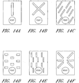
- the baffle elements may be formed into a range of shapes and patterns, for example Figures 14A to 14L illustrate wound dressings having a number of different exemplifying configurations of baffle elements.
- Figure 14A illustrates a linear baffle element in a vertical configuration aligned in the direction of the port or orifice.
- Figure 14B illustrates an X-shaped baffle element.
- Figures 14C-E illustrate embodiments of wound dressings with multiple baffle elements, aligned in a generally diagonal, horizontal, or vertical manner.
- Figure 14F illustrates baffle elements arranged in a six-armed starburst configuration, with a center portion left open.
- Figure 14G illustrates a W-shaped baffle element on the wound dressing in a position distal to the port or orifice.
- Figure 14H an 3-by-3 array of X-shaped baffle elements is provided on the wound dressing, although it will be understood that more or less X-shaped baffle elements may be used.
- Figure 14I shows an embodiment with a plurality of rectangular baffle elements, and wherein one or more baffle elements are located underneath the port in the wound dressing.
- Figures 14J-K illustrate wound dressing embodiments with longer diagonal and horizontal baffle elements.
- rectangular baffle elements are present on this embodiment of a wound dressing, wherein the baffle elements are of different sizes.
- the at least one element comprises an array of vias, or troughs, in the transmission layer 105.
- Figure 15 illustrates a transmission layer 105 that is perforated with diamond shaped vias 210.
- the vias 210 are arranged such that no linear pathway exists through the pattern of vias that does not intersect with one or more of the vias 210.
- the absorbent layer 110 When negative pressure is applied to the wound dressing, the absorbent layer 110 is drawn into the vias 210, increasing the area of the absorbent layer that comes into contact with wound exudate being drawn through the transmission layer 105.
- the vias 210 may be filled with further absorbent material for absorbing wound exudate being drawn through the transmission layer 105.
- the vias may extend through the depth of the transmission layer 105, or may extend through only part of the transmission layer.
- the vias are not limited to diamond shapes, and that any pattern of vias may be used.
- the vias will be arranged to ensure that all linear paths through the transmission layer 105 intersect with at least one via. The pattern of vias may be chosen to minimise the distance that wound exudate is able to travel though the transmission layer before encountering a via and being absorbed.
- Figure 7 illustrates a wound dressing in accordance with some embodiments of the invention in which the at least one element comprises an air channel 710 connecting the central region 201 of the wound dressing to the orifice 145.
- the air channel 710 extends from an edge region of the transmission layer 105 and connects the transmission layer to the orifice 145.
- wound exudate is drawn towards the orifice 145 by the application of negative pressure at the suction port 150.
- the air channel 710 present a relatively long serpentine path to be followed by the wound exudate before it reaches the orifice 145. This long path increases the time that negative pressure can be applied to the dressing before wound exudate traverses the distance between the transmission layer and the orifice and blocks the filter element 130, thereby increasing the time the dressing can be in use before it must be replaced.
- Figure 8 illustrates a wound dressing in accordance with one embodiment of the invention in which the at least one element comprises air channels 810 and 812 connecting the central region 201 of the wound dressing to the orifice 145.
- Channels 810 and 812 are coupled to the transmission layer at substantially opposite corners of the central region 201.
- the wound dressing shown in Figure 8 reduces the effect of gravity on the time taken for the orifice to become blocked. If the wound dressing is in an orientation in which wound exudate moves under the influence of gravity towards the edge region of the transmission layer connected to air channel 810, the effect of gravity will be to move wound exudate away from the edge region of the transmission layer coupled to air channel 812, and vice versa.
- the embodiment of Figure 8 provides alternative air channels for coupling the negative pressure to the transmission layer such that, should one air channel become blocked a remaining air channel should remain open and able to communicate the negative pressure to the transmission layer 105, thereby increasing the time before negative pressure can no longer be applied to the wound dressing and the dressing must be changed.
- FIG. 1 may depict an exemplary embodiment of the invention in accordance with the present disclosure.
- FIG. 1 may depict an exemplary embodiment of the invention.
- two or more orifices may be provided in the cover layer 140 for applying the negative pressure to the wound dressing.
- the two or more orifices can be distributed across the cover layer 140 such that if one orifice becomes blocked by wound exudate due to the wound dressing being in a particular orientation, at least one remaining orifice would be expected to remain unblocked.
- Each orifice is in fluid communication with a wound chamber defined by the wound dressing, and is therefore able to communicate the negative pressure to the wound site.
- Figure 9 illustrates a wound dressing in accordance with a further embodiment of the invention.
- the wound dressing of figure 9 is similar to that of Figure 1 but includes two orifices 145 and 845 provided in the cover layer 140.
- a fluid communication passage connects the two orifices such that a negative pressure applied to one of the orifices is communicated to the remaining orifice via the fluid communication passage.
- the orifices 145, 845 are located in opposite corner regions of the cover layer 140.
- the fluid communication passage is formed using a flexible moulding 910 on the upper surface of the cover layer 140.
- the flexible moulding may be formed from other suitable means for example a strip of transmission or open porous foam layer placed on the cover layer 140 between the orifices 145 and 845 and a further film welded or adhered over the strip thus sealing it to the cover layer and forming a passageway through the foam.
- a conduit may then be attached in a known manner to the sealing film for application of negative pressure.
- the wound dressing having two orifices is sealed over a wound site to form a wound cavity and an external source of negative pressure is applied to one of the orifices 145, 845, and the negative pressure will be communicated to the remaining orifice via the fluid communication passage.
- the negative pressure is communicated via the two orifices 145, 845 to the transmission layer 105, and thereby to the wound site. If one of the orifices 145, 845 becomes blocked due to wound exudate collecting at the orifice under the influence of gravity, the remaining orifice should remain clear, allowing negative pressure to continue to be communicated to the wound site.
- the transmission layer 105 may be omitted, and the two orifices will communicate the negative pressure to the wound site via the absorbent layer 110.
- Figure 10 illustrates a side view of the fluid communication passage of the embodiment of figure 9 .
- Moulding 910 is sealed to the top surface of the cover layer 140, and covering orifices 145 and 845.
- Gas permeable liquid impermeable filter elements 130 are provided at each orifice.
- the moulding 910 is coupled to an external source of negative pressure via a tube element 220.
- a single filter element may be used extending underneath the length of the fluid communication passage and the two orifices. While the above example embodiment has been described as having two orifices, it will be understood that more than two orifices could be used, the fluid communication passage allowing the negative pressure to be communicated between the orifices.
- Figure 16 illustrates an alternative arrangement in which a single elongate orifice 350 is provided in the cover layer 140.
- First and second ends 355, 356 of the orifice 350 are located in opposite corner regions of the cover layer 140.
- a flexible molding 360 is sealed around the orifice 350 and allows negative pressure to be communicated through the cover layer 140 along the length of the orifice 350.
- the flexible moulding 360 may be formed by any suitable means as described above in relation to flexible moulding 910.
- the wound dressing In use, the wound dressing is sealed over a wound site to form a wound cavity and an external source of negative pressure is applied to the orifice. If, due to the orientation of the wound dressing, wound exudate moves under the influence of gravity to collect around one end 355 of the orifice 350, a portion of the orifice 350 near to the end 355 will become blocked. However, a portion of the orifice near to the remaining end 356 should remain clear, allowing continued application of negative pressure to the wound site.
- the dressing can contain anti-microbial e.g. nanocrystalline silver agents on the wound contact layer and/or silver sulphur diazine in the absorbent layer. These may be used separately or together. These respectively kill micro-organisms in the wound and micro-organisms in the absorption matrix.
- active components for example, pain suppressants, such as ibuprofen, may be included.
- agents which enhance cell activity such as growth factors or that inhibit enzymes, such as matrix metalloproteinase inhibitors, such as tissue inhibitors of metalloproteinase (TIMPS) or zinc chelators could be utilised.
- odour trapping elements such as activated carbon, cyclodextrine, zealite or the like may be included in the absorbent layer or as a still further layer above the filter layer.
- the dressing may be used "up-side down", at an angle or vertical. References to upper and lower are thus used for explanation purposes only.
- FIG 17 illustrates an embodiment of a TNP wound treatment comprising a wound dressing 100 in combination with a pump 800.
- the dressing 100 may be placed over a wound as described previously, and a conduit 220 may then be connected to the port 150, although in some embodiments the dressing 100 may be provided with at least a portion of the conduit 220 preattached to the port 150.
- the dressing 100 is provided as a single article with all wound dressing elements (including the port 150) preattached and integrated into a single unit.
- the wound dressing 100 may then be connected, via the conduit 220, to a source of negative pressure such as the pump 800.
- the pump 800 is miniaturized and portable, although larger conventional pumps may also be used with the dressing 100.
- the pump 800 may be attached or mounted onto or adjacent the dressing 100.
- a connector 221 may also be provided so as to permit the conduit 220 leading to the wound dressing 100 to be disconnected from the pump, which may be useful for example during dressing changes.
- Figures 18A-D illustrate the use of an embodiment of a TNP wound treatment system being used to treat a wound site on a patient.
- Figure 18A shows a wound site 190 being cleaned and prepared for treatment.
- the healthy skin surrounding the wound site 190 is preferably cleaned and excess hair removed or shaved.
- the wound site 190 may also be irrigated with sterile saline solution if necessary.
- a skin protectant may be applied to the skin surrounding the wound site 190.
- a wound packing material such as foam or gauze, may be placed in the wound site 190. This may be preferable if the wound site 190 is a deeper wound.
- the wound dressing 100 may be positioned and placed over the wound site 190.
- the wound dressing 100 is placed with the wound contact layer 102 over and/or in contact with the wound site 190.
- an adhesive layer is provided on the lower surface 101 of the wound contact layer 102, which may in some cases be protected by an optional release layer to be removed prior to placement of the wound dressing 100 over the wound site 190.
- the dressing 100 is positioned such that the port 150 is in a raised position with respect to the remainder of the dressing 100 so as to avoid fluid pooling around the port.
- the dressing 100 is positioned so that the port 150 is not directly overlying the wound, and is level with or at a higher point than the wound.
- the edges of the dressing 100 are preferably smoothed over to avoid creases or folds.
- the dressing 100 is connected to the pump 800.
- the pump 800 is configured to apply negative pressure to the wound site via the dressing 100, and typically through a conduit.
- a connector may be used to join the conduit from the dressing 100 to the pump 800.
- the dressing 100 may in some embodiments partially collapse and present a wrinkled appearance as a result of the evacuation of some or all of the air underneath the dressing 100.
- the pump 800 may be configured to detect if any leaks are present in the dressing 100, such as at the interface between the dressing 100 and the skin surrounding the wound site 190. Should a leak be found, such leak is preferably remedied prior to continuing treatment.
- fixation strips 195 may also be attached around the edges of the dressing 100. Such fixation strips 195 may be advantageous in some situations so as to provide additional sealing against the skin of the patient surrounding the wound site 190. For example, the fixation strips 195 may provide additional sealing for when a patient is more mobile. In some cases, the fixation strips 195 may be used prior to activation of the pump 800, particularly if the dressing 100 is placed over a difficult to reach or contoured area.
- Treatment of the wound site 190 preferably continues until the wound has reached a desired level of healing.
Applications Claiming Priority (3)
| Application Number | Priority Date | Filing Date | Title |
|---|---|---|---|
| GBGB1006988.8A GB201006988D0 (en) | 2010-04-27 | 2010-04-27 | Suction port |
| PCT/GB2011/000628 WO2011135287A1 (en) | 2010-04-27 | 2011-04-21 | Suction port |
| EP11722123.4A EP2563422B8 (en) | 2010-04-27 | 2011-04-21 | Suction port |
Related Parent Applications (2)
| Application Number | Title | Priority Date | Filing Date |
|---|---|---|---|
| EP11722123.4A Division-Into EP2563422B8 (en) | 2010-04-27 | 2011-04-21 | Suction port |
| EP11722123.4A Division EP2563422B8 (en) | 2010-04-27 | 2011-04-21 | Suction port |
Publications (1)
| Publication Number | Publication Date |
|---|---|
| EP3539579A1 true EP3539579A1 (en) | 2019-09-18 |
Family
ID=42270878
Family Applications (2)
| Application Number | Title | Priority Date | Filing Date |
|---|---|---|---|
| EP11722123.4A Active EP2563422B8 (en) | 2010-04-27 | 2011-04-21 | Suction port |
| EP19166574.4A Pending EP3539579A1 (en) | 2010-04-27 | 2011-04-21 | Suction port |
Family Applications Before (1)
| Application Number | Title | Priority Date | Filing Date |
|---|---|---|---|
| EP11722123.4A Active EP2563422B8 (en) | 2010-04-27 | 2011-04-21 | Suction port |
Country Status (12)
| Country | Link |
|---|---|
| EP (2) | EP2563422B8 (zh) |
| JP (2) | JP5837049B2 (zh) |
| CN (2) | CN106943636B (zh) |
| AU (1) | AU2011247127B2 (zh) |
| BR (1) | BR112012027620A2 (zh) |
| CA (1) | CA2797595C (zh) |
| ES (1) | ES2744469T3 (zh) |
| GB (1) | GB201006988D0 (zh) |
| MX (1) | MX338433B (zh) |
| RU (1) | RU2560973C2 (zh) |
| WO (1) | WO2011135287A1 (zh) |
| ZA (1) | ZA201208055B (zh) |
Families Citing this family (65)
| Publication number | Priority date | Publication date | Assignee | Title |
|---|---|---|---|---|
| GB0224986D0 (en) | 2002-10-28 | 2002-12-04 | Smith & Nephew | Apparatus |
| GB0325129D0 (en) | 2003-10-28 | 2003-12-03 | Smith & Nephew | Apparatus in situ |
| US10058642B2 (en) | 2004-04-05 | 2018-08-28 | Bluesky Medical Group Incorporated | Reduced pressure treatment system |
| EP1922045B1 (en) | 2005-09-07 | 2012-11-07 | Tyco Healthcare Group LP | Self contained wound dressing with micropump |
| US7779625B2 (en) | 2006-05-11 | 2010-08-24 | Kalypto Medical, Inc. | Device and method for wound therapy |
| CA2705896C (en) | 2007-11-21 | 2019-01-08 | Smith & Nephew Plc | Wound dressing |
| HUE043133T2 (hu) | 2007-11-21 | 2019-07-29 | Smith & Nephew | Sebkötözés |
| GB0722820D0 (en) | 2007-11-21 | 2008-01-02 | Smith & Nephew | Vacuum assisted wound dressing |
| GB0723855D0 (en) | 2007-12-06 | 2008-01-16 | Smith & Nephew | Apparatus and method for wound volume measurement |
| US8152785B2 (en) | 2008-03-13 | 2012-04-10 | Tyco Healthcare Group Lp | Vacuum port for vacuum wound therapy |
| US9061095B2 (en) | 2010-04-27 | 2015-06-23 | Smith & Nephew Plc | Wound dressing and method of use |
| GB201015656D0 (en) | 2010-09-20 | 2010-10-27 | Smith & Nephew | Pressure control apparatus |
| AU2011333538C1 (en) | 2010-11-25 | 2015-07-30 | Bluestar Silicones France Sas | Composition I-II and products and uses thereof |
| GB201020005D0 (en) | 2010-11-25 | 2011-01-12 | Smith & Nephew | Composition 1-1 |
| CN106974683B (zh) | 2011-02-04 | 2020-02-21 | 马萨诸塞州大学 | 负压伤口闭合装置 |
| US9421132B2 (en) | 2011-02-04 | 2016-08-23 | University Of Massachusetts | Negative pressure wound closure device |
| GB201108229D0 (en) | 2011-05-17 | 2011-06-29 | Smith & Nephew | Tissue healing |
| US9084845B2 (en) | 2011-11-02 | 2015-07-21 | Smith & Nephew Plc | Reduced pressure therapy apparatuses and methods of using same |
| US20150159066A1 (en) | 2011-11-25 | 2015-06-11 | Smith & Nephew Plc | Composition, apparatus, kit and method and uses thereof |
| WO2013136181A2 (en) | 2012-03-12 | 2013-09-19 | Smith & Nephew Plc | Reduced pressure apparatus and methods |
| US9901664B2 (en) | 2012-03-20 | 2018-02-27 | Smith & Nephew Plc | Controlling operation of a reduced pressure therapy system based on dynamic duty cycle threshold determination |
| US9427505B2 (en) | 2012-05-15 | 2016-08-30 | Smith & Nephew Plc | Negative pressure wound therapy apparatus |
| CA2874396A1 (en) | 2012-05-22 | 2014-01-23 | Smith & Nephew Plc | Wound closure device |
| WO2013175310A2 (en) | 2012-05-22 | 2013-11-28 | Smith & Nephew Plc | Apparatuses and methods for wound therapy |
| DK3354293T3 (da) | 2012-05-23 | 2020-02-17 | Smith & Nephew | Apparater til sårbehandling ved negativt tryk |
| CA2874581C (en) | 2012-05-24 | 2022-06-07 | Smith & Nephew Inc. | Devices and methods for treating and closing wounds with negative pressure |
| AU2013290346B2 (en) | 2012-07-16 | 2018-06-07 | Smith & Nephew, Inc. | Negative pressure wound closure device |
| CN104661626B (zh) | 2012-08-01 | 2018-04-06 | 史密夫及内修公开有限公司 | 伤口敷料 |
| US10667955B2 (en) | 2012-08-01 | 2020-06-02 | Smith & Nephew Plc | Wound dressing and method of treatment |
| GB201317746D0 (en) | 2013-10-08 | 2013-11-20 | Smith & Nephew | PH indicator |
| EP2968016B1 (en) | 2013-03-13 | 2018-07-11 | Smith&Nephew, Inc. | Negative pressure wound closure device and systems and methods of use in treating wounds with negative pressure |
| US10159771B2 (en) | 2013-03-14 | 2018-12-25 | Smith & Nephew Plc | Compressible wound fillers and systems and methods of use in treating wounds with negative pressure |
| US10493184B2 (en) | 2013-03-15 | 2019-12-03 | Smith & Nephew Plc | Wound dressing and method of treatment |
| US10695226B2 (en) | 2013-03-15 | 2020-06-30 | Smith & Nephew Plc | Wound dressing and method of treatment |
| US20160120706A1 (en) | 2013-03-15 | 2016-05-05 | Smith & Nephew Plc | Wound dressing sealant and use thereof |
| JP6723917B2 (ja) | 2013-10-21 | 2020-07-15 | スミス アンド ネフュー インコーポレイテッド | 陰圧創傷閉鎖デバイス |
| CN103623470A (zh) * | 2013-12-10 | 2014-03-12 | 谭世令 | 一种抽胸腹水装置 |
| JP6742908B2 (ja) | 2014-01-21 | 2020-08-19 | スミス アンド ネフュー ピーエルシーSmith & Nephew Public Limited Company | 潰すことが可能な陰圧創傷治療用被覆材 |
| US11439734B2 (en) * | 2014-03-31 | 2022-09-13 | Koninklijke Philips N.V. | Breast pump and expression kit for a breast pump |
| EP3157484B1 (en) | 2014-06-18 | 2020-02-26 | Smith & Nephew plc | Wound dressing |
| JP6991067B2 (ja) | 2014-12-22 | 2022-01-12 | スミス アンド ネフュー ピーエルシー | 陰圧閉鎖療法の装置および方法 |
| EP3288509B1 (en) | 2015-04-29 | 2022-06-29 | Smith & Nephew, Inc | Negative pressure wound closure device |
| US10076594B2 (en) | 2015-05-18 | 2018-09-18 | Smith & Nephew Plc | Fluidic connector for negative pressure wound therapy |
| US10449094B2 (en) * | 2015-10-30 | 2019-10-22 | Lorain County Community College Innovation Foundation | Wound therapy device and method |
| DE102015224746A1 (de) * | 2015-12-09 | 2017-06-14 | Paul Hartmann Ag | Anschlussvorrichtung zur Verwendung bei der Unterdrucktherapie von Wunden |
| US10814049B2 (en) | 2015-12-15 | 2020-10-27 | University Of Massachusetts | Negative pressure wound closure devices and methods |
| US11471586B2 (en) | 2015-12-15 | 2022-10-18 | University Of Massachusetts | Negative pressure wound closure devices and methods |
| US10575991B2 (en) | 2015-12-15 | 2020-03-03 | University Of Massachusetts | Negative pressure wound closure devices and methods |
| CN108472160B (zh) | 2015-12-30 | 2022-02-22 | 史密夫及内修公开有限公司 | 负压伤口疗法设备 |
| EP3397219B1 (en) | 2015-12-30 | 2020-10-21 | Smith & Nephew plc | Absorbent negative pressure wound therapy dressing |
| JP1586116S (zh) | 2016-02-29 | 2017-09-19 | ||
| USD796735S1 (en) | 2016-02-29 | 2017-09-05 | Smith & Nephew Plc | Mount apparatus for portable negative pressure apparatus |
| US11771820B2 (en) | 2016-03-04 | 2023-10-03 | Smith & Nephew Plc | Negative pressure wound therapy apparatus for post breast surgery wounds |
| EP3551147B1 (en) | 2016-12-12 | 2023-08-09 | Smith & Nephew PLC | Wound dressing |
| CN106821596B (zh) * | 2016-12-22 | 2022-10-21 | 浙江海创医疗器械有限公司 | 一种低致敏性强力加压吸液敷贴 |
| US11179512B2 (en) * | 2017-06-07 | 2021-11-23 | Kci Licensing, Inc. | Multi-layer wound filler for extended wear time |
| WO2018229008A1 (en) | 2017-06-14 | 2018-12-20 | Smith & Nephew Plc | Negative pressure wound therapy apparatus |
| US20200261276A1 (en) * | 2017-11-08 | 2020-08-20 | University Of Massachusetts | Post-Operative Hybrid Dressing To Optimize Skin-Grafting Procedures In Reconstructive Surgery |
| US11224543B2 (en) | 2018-05-03 | 2022-01-18 | Kci Licensing, Inc. | Negative pressure wound therapy system with detection of full absorbent dressing |
| GB201811449D0 (en) | 2018-07-12 | 2018-08-29 | Smith & Nephew | Apparatuses and methods for negative pressure wound therapy |
| WO2020060870A1 (en) * | 2018-09-17 | 2020-03-26 | Kci Licensing, Inc. | Negative pressure wound therapy system |
| EP3906000A4 (en) | 2018-12-31 | 2022-06-22 | Clippert, Geof | CLOSABLE DRESSING |
| DE202019101382U1 (de) * | 2019-03-12 | 2020-06-15 | Lohmann & Rauscher Gmbh | Unterdruckbehandlungsanordnung |
| EP4017446A1 (en) * | 2019-08-20 | 2022-06-29 | KCI Licensing, Inc. | Gel-blocking connection assembly for absorbent negative pressure dressing |
| EP4274530A1 (en) * | 2021-01-06 | 2023-11-15 | Sunmedic AB | Negative pressure wound therapy systems |
Citations (6)
| Publication number | Priority date | Publication date | Assignee | Title |
|---|---|---|---|---|
| US20020161346A1 (en) * | 2000-11-29 | 2002-10-31 | Lockwood Jeffrey S. | Vacuum therapy and cleansing dressing for wounds |
| US20050222544A1 (en) * | 2004-04-05 | 2005-10-06 | Weston Richard S | Flexible reduced pressure treatment appliance |
| US20070265585A1 (en) * | 2006-05-11 | 2007-11-15 | Joshi Ashok V | Device and method for wound therapy |
| WO2009066106A1 (en) * | 2007-11-21 | 2009-05-28 | Smith & Nephew Plc | Wound dressing |
| US20090227969A1 (en) * | 2008-03-05 | 2009-09-10 | Jonathan Paul Jaeb | Dressing and method for applying reduced pressure to and collecting and storing fluid from a tissue site |
| WO2010008167A2 (en) * | 2008-07-14 | 2010-01-21 | Bioalpha Inc. | Medical suction head |
Family Cites Families (6)
| Publication number | Priority date | Publication date | Assignee | Title |
|---|---|---|---|---|
| MX2008009755A (es) * | 2006-02-06 | 2009-03-05 | Kci Licensing Inc | Sistemas y metodos para la conexion mejorada hacia apositos de heridas en conjunto con sistemas de presion reducida para el tratamiento de heridas. |
| RU70627U1 (ru) * | 2007-09-17 | 2008-02-10 | Вадим Владимирович Белов | Устройство для вакуумной терапии гнойных ран |
| CA2705896C (en) * | 2007-11-21 | 2019-01-08 | Smith & Nephew Plc | Wound dressing |
| GB0723874D0 (en) * | 2007-12-06 | 2008-01-16 | Smith & Nephew | Dressing |
| JP2011516170A (ja) * | 2008-04-04 | 2011-05-26 | スリーエム イノベイティブ プロパティズ カンパニー | バルブを備える医療用手当て用品及びこれを含むキット |
| MX2010013132A (es) * | 2008-05-30 | 2010-12-20 | Kci Licensing Inc | Sistemas de presion reducida para el tratamiento de heridas lineales. |
-
2010
- 2010-04-27 GB GBGB1006988.8A patent/GB201006988D0/en not_active Ceased
-
2011
- 2011-04-21 MX MX2012012548A patent/MX338433B/es active IP Right Grant
- 2011-04-21 WO PCT/GB2011/000628 patent/WO2011135287A1/en active Application Filing
- 2011-04-21 EP EP11722123.4A patent/EP2563422B8/en active Active
- 2011-04-21 CA CA2797595A patent/CA2797595C/en active Active
- 2011-04-21 BR BR112012027620A patent/BR112012027620A2/pt not_active Application Discontinuation
- 2011-04-21 CN CN201611138741.1A patent/CN106943636B/zh active Active
- 2011-04-21 CN CN201180031860.6A patent/CN103096946B/zh active Active
- 2011-04-21 AU AU2011247127A patent/AU2011247127B2/en active Active
- 2011-04-21 EP EP19166574.4A patent/EP3539579A1/en active Pending
- 2011-04-21 ES ES11722123T patent/ES2744469T3/es active Active
- 2011-04-21 JP JP2013506731A patent/JP5837049B2/ja active Active
- 2011-04-21 RU RU2012150132/14A patent/RU2560973C2/ru active
-
2012
- 2012-10-25 ZA ZA2012/08055A patent/ZA201208055B/en unknown
-
2015
- 2015-11-04 JP JP2015216563A patent/JP6275678B2/ja active Active
Patent Citations (6)
| Publication number | Priority date | Publication date | Assignee | Title |
|---|---|---|---|---|
| US20020161346A1 (en) * | 2000-11-29 | 2002-10-31 | Lockwood Jeffrey S. | Vacuum therapy and cleansing dressing for wounds |
| US20050222544A1 (en) * | 2004-04-05 | 2005-10-06 | Weston Richard S | Flexible reduced pressure treatment appliance |
| US20070265585A1 (en) * | 2006-05-11 | 2007-11-15 | Joshi Ashok V | Device and method for wound therapy |
| WO2009066106A1 (en) * | 2007-11-21 | 2009-05-28 | Smith & Nephew Plc | Wound dressing |
| US20090227969A1 (en) * | 2008-03-05 | 2009-09-10 | Jonathan Paul Jaeb | Dressing and method for applying reduced pressure to and collecting and storing fluid from a tissue site |
| WO2010008167A2 (en) * | 2008-07-14 | 2010-01-21 | Bioalpha Inc. | Medical suction head |
Also Published As
| Publication number | Publication date |
|---|---|
| EP2563422B1 (en) | 2019-06-26 |
| AU2011247127A2 (en) | 2013-02-14 |
| JP5837049B2 (ja) | 2015-12-24 |
| CN106943636A (zh) | 2017-07-14 |
| CA2797595C (en) | 2020-03-24 |
| CN106943636B (zh) | 2020-06-30 |
| EP2563422A1 (en) | 2013-03-06 |
| JP2013524973A (ja) | 2013-06-20 |
| MX338433B (es) | 2016-04-14 |
| AU2011247127A1 (en) | 2012-11-08 |
| MX2012012548A (es) | 2013-04-03 |
| CN103096946B (zh) | 2017-01-18 |
| RU2560973C2 (ru) | 2015-08-20 |
| JP6275678B2 (ja) | 2018-02-07 |
| CA2797595A1 (en) | 2011-11-03 |
| JP2016026058A (ja) | 2016-02-12 |
| ZA201208055B (en) | 2013-06-26 |
| BR112012027620A2 (pt) | 2016-08-09 |
| AU2011247127B2 (en) | 2015-05-14 |
| RU2012150132A (ru) | 2014-06-10 |
| WO2011135287A1 (en) | 2011-11-03 |
| CN103096946A (zh) | 2013-05-08 |
| GB201006988D0 (en) | 2010-06-09 |
| EP2563422B8 (en) | 2019-08-07 |
| ES2744469T3 (es) | 2020-02-25 |
Similar Documents
| Publication | Publication Date | Title |
|---|---|---|
| EP4023197B1 (en) | Wound dressing | |
| EP2563307B1 (en) | Wound dressing | |
| EP2563422B1 (en) | Suction port | |
| EP2563306B1 (en) | Wound dressing | |
| AU2015201022B2 (en) | Wound protection | |
| EP2699276B1 (en) | Blockage management | |
| US20150320604A1 (en) | Wound dressing and method of use |
Legal Events
| Date | Code | Title | Description |
|---|---|---|---|
| PUAI | Public reference made under article 153(3) epc to a published international application that has entered the european phase |
Free format text: ORIGINAL CODE: 0009012 |
|
| STAA | Information on the status of an ep patent application or granted ep patent |
Free format text: STATUS: THE APPLICATION HAS BEEN PUBLISHED |
|
| AC | Divisional application: reference to earlier application |
Ref document number: 2563422 Country of ref document: EP Kind code of ref document: P |
|
| AK | Designated contracting states |
Kind code of ref document: A1 Designated state(s): AL AT BE BG CH CY CZ DE DK EE ES FI FR GB GR HR HU IE IS IT LI LT LU LV MC MK MT NL NO PL PT RO RS SE SI SK SM TR |
|
| STAA | Information on the status of an ep patent application or granted ep patent |
Free format text: STATUS: REQUEST FOR EXAMINATION WAS MADE |
|
| 17P | Request for examination filed |
Effective date: 20200318 |
|
| RBV | Designated contracting states (corrected) |
Designated state(s): AL AT BE BG CH CY CZ DE DK EE ES FI FR GB GR HR HU IE IS IT LI LT LU LV MC MK MT NL NO PL PT RO RS SE SI SK SM TR |
|
| STAA | Information on the status of an ep patent application or granted ep patent |
Free format text: STATUS: EXAMINATION IS IN PROGRESS |
|
| 17Q | First examination report despatched |
Effective date: 20230421 |