EP3539094B2 - Vorrichtung und verfahren zur detektion der position einer vorrichtung zur versetzung eines fensters in mindestens drei unterschiedliche zustände - Google Patents
Vorrichtung und verfahren zur detektion der position einer vorrichtung zur versetzung eines fensters in mindestens drei unterschiedliche zustände Download PDFInfo
- Publication number
- EP3539094B2 EP3539094B2 EP17808347.3A EP17808347A EP3539094B2 EP 3539094 B2 EP3539094 B2 EP 3539094B2 EP 17808347 A EP17808347 A EP 17808347A EP 3539094 B2 EP3539094 B2 EP 3539094B2
- Authority
- EP
- European Patent Office
- Prior art keywords
- window
- different states
- putting
- detecting
- movable element
- Prior art date
- Legal status (The legal status is an assumption and is not a legal conclusion. Google has not performed a legal analysis and makes no representation as to the accuracy of the status listed.)
- Active
Links
Images

Classifications
-
- G—PHYSICS
- G08—SIGNALLING
- G08B—SIGNALLING OR CALLING SYSTEMS; ORDER TELEGRAPHS; ALARM SYSTEMS
- G08B13/00—Burglar, theft or intruder alarms
- G08B13/02—Mechanical actuation
- G08B13/08—Mechanical actuation by opening, e.g. of door, of window, of drawer, of shutter, of curtain, of blind
-
- E—FIXED CONSTRUCTIONS
- E05—LOCKS; KEYS; WINDOW OR DOOR FITTINGS; SAFES
- E05D—HINGES OR SUSPENSION DEVICES FOR DOORS, WINDOWS OR WINGS
- E05D15/00—Suspension arrangements for wings
- E05D15/48—Suspension arrangements for wings allowing alternative movements
- E05D15/52—Suspension arrangements for wings allowing alternative movements for opening about a vertical as well as a horizontal axis
-
- E—FIXED CONSTRUCTIONS
- E05—LOCKS; KEYS; WINDOW OR DOOR FITTINGS; SAFES
- E05F—DEVICES FOR MOVING WINGS INTO OPEN OR CLOSED POSITION; CHECKS FOR WINGS; WING FITTINGS NOT OTHERWISE PROVIDED FOR, CONCERNED WITH THE FUNCTIONING OF THE WING
- E05F11/00—Man-operated mechanisms for operating wings, including those which also operate the fastening
- E05F11/02—Man-operated mechanisms for operating wings, including those which also operate the fastening for wings in general, e.g. fanlights
- E05F11/08—Man-operated mechanisms for operating wings, including those which also operate the fastening for wings in general, e.g. fanlights with longitudinally-moving bars guided, e.g. by pivoted links, in or on the frame
- E05F11/10—Mechanisms by which a handle moves the bar
-
- G—PHYSICS
- G08—SIGNALLING
- G08B—SIGNALLING OR CALLING SYSTEMS; ORDER TELEGRAPHS; ALARM SYSTEMS
- G08B25/00—Alarm systems in which the location of the alarm condition is signalled to a central station, e.g. fire or police telegraphic systems
- G08B25/01—Alarm systems in which the location of the alarm condition is signalled to a central station, e.g. fire or police telegraphic systems characterised by the transmission medium
- G08B25/10—Alarm systems in which the location of the alarm condition is signalled to a central station, e.g. fire or police telegraphic systems characterised by the transmission medium using wireless transmission systems
-
- E—FIXED CONSTRUCTIONS
- E05—LOCKS; KEYS; WINDOW OR DOOR FITTINGS; SAFES
- E05B—LOCKS; ACCESSORIES THEREFOR; HANDCUFFS
- E05B47/00—Operating or controlling locks or other fastening devices by electric or magnetic means
- E05B2047/0048—Circuits, feeding, monitoring
- E05B2047/0067—Monitoring
- E05B2047/0068—Door closed
-
- E—FIXED CONSTRUCTIONS
- E05—LOCKS; KEYS; WINDOW OR DOOR FITTINGS; SAFES
- E05Y—INDEXING SCHEME ASSOCIATED WITH SUBCLASSES E05D AND E05F, RELATING TO CONSTRUCTION ELEMENTS, ELECTRIC CONTROL, POWER SUPPLY, POWER SIGNAL OR TRANSMISSION, USER INTERFACES, MOUNTING OR COUPLING, DETAILS, ACCESSORIES, AUXILIARY OPERATIONS NOT OTHERWISE PROVIDED FOR, APPLICATION THEREOF
- E05Y2400/00—Electronic control; Electrical power; Power supply; Power or signal transmission; User interfaces
- E05Y2400/80—User interfaces
- E05Y2400/81—Feedback to user, e.g. tactile
Definitions
- the present invention relates to a method and a device for detecting the position of a device for placing a window in at least three different states.
- Openings such as windows offer different opening possibilities.
- windows with a French, English, bellows opening mechanism or combining two opening mechanisms such as tilt-and-turn windows.
- French windows are equipped with leaf openings that pivot vertically on their edge towards the inside, with hinges on the frame. They are often supplemented by a fixed horizontal frame located under the opening leaf.
- Tilt-and-turn windows can be opened by tilting on a horizontal axis, known as a bellows, or on a vertical axis in the French style. Tilting on a horizontal axis allows in particular opening from above.
- the tilt-and-turn window can be operated in two ways, using a traditional system, similar to French windows or by vertical hinges allowing the leaf to open inwards and allowing rapid air renewal, but by not allowing an individual to enter.
- the need is felt today to be able to notify the building occupant of the state of a tilt-and-turn window.
- Patent applications US 2016/231349 , FROM 101 61 761 and the patent US 6,472,993 disclose a device and method for determining the states of a window to be monitored.
- the patent application EP 2 267 744 discloses a device for detecting the movement of an opening or a frame.
- the patent application WO 2005/066440 discloses a device making it possible to determine the position of a handle via a moving part cooperating with 3 microswitches, integrated into said handle. The status of the microswitches is transmitted by means of a radio module.
- the present invention aims to resolve the drawbacks of the prior art by proposing a method and a device for detecting the position of a device for placing a window in at least three different states.
- the device for detecting the position of the device for placing the window in at least three different states identifies the position of the device for placing the window in at least three different states such as the locking position
- the device for detecting the position of the window setting device in at least three different states identifies the position of the window setting device window in at least three different states such as the French open position
- the device for detecting the position of the device for placing the window in at least three different states identifies the position of the device for placing the window in at least three different states such as the bellows opening position.
- the invention also relates to computer programs stored on an information medium, said programs comprising instructions making it possible to implement the methods described above, when they are loaded and executed by a computer system.
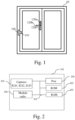
- FIG. 1 represents an opening of a building equipped with a device for detecting the position of a device for placing a window in at least three different states according to the present invention.
- Window 10 is a tilt-and-turn window.
- the oscillating system allows the window to be opened by tilting the leaf inwards, in its upper part.
- the vertical hinges are left inactive, while the leaf is held by a mechanical arm on the upper part of the window. This prevents any intrusion from the outside while leaving the passage of air free.
- This type of window is particularly widespread in residential buildings, because the oscillating system prevents any burglary while guaranteeing security. aeration.
- the window 10 includes a device for putting the opening in at least three different states.
- the device for placing the window in at least three different states has a different position for three different states of the window 10.
- the window is in a bellows opening, i.e. a tilting of the leaf towards the inside, in its upper part.
- the window is open French style.
- the window is locked, that is to say closed.
- the window 10 includes a device 100 for detecting the position of the device for placing a window in at least three different states.
- the device 100 for detecting the position of the device for placing a window in at least three different states and placed on the window frame comprises sensors which are capable of detecting the position of a movable element 110 placed on the opening of the window.
- the movable element is mechanically coupled to the device for setting the window in at least three different states and takes different positions depending on the position of the device for setting the window in at least three different states.
- the mechanical coupling is for example provided by a movable rod of the window cremone.
- the moving element is a magnet and each sensor is a flexible reed switch (ILS) which allows or not electrical contact depending on whether the magnet is in proximity to the sensor or not.
- ILS flexible reed switch
- the device 100 for detecting the position of the device for placing a window in at least three different states is powered by battery or battery.
- FIG. 2 represents an example of architecture for detecting the position of the device for placing a window in at least three different states according to the present invention.
- the processor 200 is capable of executing instructions loaded into the volatile memory 203 from the non-volatile memory 202, a storage medium, such as an SD card or the like, or a communication network.
- the processor 200 is capable of reading instructions from the volatile memory 203 and executing them.
- These instructions form a computer program which causes the implementation, by the processor 200, of all or part of the method described in relation to the Fig. 4 .
- All or part of the process described in relation to the Fig. 4 can be implemented in software form by execution of a set of instructions by a programmable machine, such as a DSP ( Digital Signal Processor in English or Digital Signal Processing Unit in French) or a microcontroller, or be implemented in software form hardware by a machine or a dedicated component, such as an FPGA ( Field-Programmable Gate Array in English or Matrice de Portes Programmable sur le Terrain in French) or an ASIC ( Application-Specific Integrated Circuit in English or Integrated Circuit Specific to a Application in French).
- a programmable machine such as a DSP ( Digital Signal Processor in English or Digital Signal Processing Unit in French) or a microcontroller
- a machine or a dedicated component such as an FPGA ( Field-Programmable Gate Array in English or Matrice de Portes Programmable sur le Terrain in French) or an ASIC ( Application-Specific Integrated Circuit in English or Integrated Circuit Specific to a Application in French).
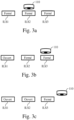
- THE Figs. 3 represent the different positions taken by a movable element placed on the window opening in relation to sensors included in the device for detecting the position of the device for placing a window in at least three different states according to the present invention.
- the movable element is a magnet and the sensors ILS1 to ILS3 are flexible blade switches which authorize or not electrical contact depending on whether the magnet 110 is in proximity or not to the sensors ILS1 to ILS3.
- the mobile element 110 is placed opposite the ILS2 sensor.
- the mobile element 110 is a magnet whose remanent magnetization and coercive field are large and which allow the movement of the flexible blades of the sensors ILS1 to ILS3 in a state allowing the passage of an electric current in the sensors ILS1 to ILS3.
- the passage of an electric current in the three sensors ILS1 to ILS3 is detected by the processor 200 as representative of the locking state of the window.
- the mobile element 110 is placed opposite the ILS3 sensor.
- the remanent magnetization and the coercive field of the magnet 110 allow the movement of the flexible blades of the ILS2 and ILS3 sensors in a state allowing the passage of an electric current in the ILS2 and ILS3 sensors and not in the ILS1 sensor.
- the passage of an electric current in the ILS2 and ILS3 sensors and not in the ILS1 sensor is detected by the processor 200 as representative of the opening state of the French window.
- the mobile element 110 is not placed opposite any of the sensors ILS1 to ILS3 but is placed near the sensor ILS3.
- the remanent magnetization and the coercive field of the magnet 110 allow the flexible blade of the ILS3 sensor to move into a state allowing the passage of an electric current in the ILS3 sensor and not in the ILS1 and ILS2 sensors.
- the passage of an electric current in the ILS3 sensor and not in the ILS1 and ILS2 sensors is detected by the processor 200 as representative of the opening state of the bellows window.
- a fourth state can also be detected.
- the mobile element 110 is not placed opposite any of the sensors ILS1 to ILS3 and is not placed near the sensor ILS3.
- the remanent magnetization and the coercive field of the magnet 110 do not allow the flexible blades of the sensors ILS1 to ILS3 to move in a state allowing the passage of an electric current in the sensors ILS1 to ILS3.
- the remanent magnetization and the coercive field of the magnet are sized to ensure compatibility with the ILS1 and ILS3 sensors as well as their positioning relative to each other.
- Fig. 4 represents an algorithm, executed by the device detecting the position of the device for placing a window in at least three different states according to the present invention.
- the present algorithm is described in an example in which it is executed by the processor 200 of the device for detecting the position of the device for placing a window in at least three different states.
- step E400 the processor 200 reads the state of the sensors ILS1 to ILS3. More precisely, the processor 200 checks whether the flexible blades of the sensors ILS1 to ILS3 are in a state allowing the passage or not of an electric current in the sensors ILS1 to ILS3.
- the processor 200 checks whether the state of the sensors ILS1 to IL3 is modified compared to the state stored in the previous execution of this algorithm.
- processor 200 If the state of the sensors ILS1 to ILS3 is modified compared to the state stored in the previous execution of this algorithm, the processor 200 goes to step E403. If not, processor 200 returns to step E400.
- the processor 200 checks whether the flexible blades of the sensors ILS1 to ILS3 are in a state allowing the passage of an electric current in the sensors ILS1 to ILS3.
- step E406 If so, the processor 200 goes to step E410.
- step E406 the processor 200 determines, from the detection of the passage of an electric current in the three sensors ILS1 to ILS3, that the window is locked.
- step E407 the processor 200 controls the transfer of a frame via the radio module 406 to a remote device.
- the remote device is, for example, a home automation gateway, an alarm center or a smart mobile phone.
- the transferred frame includes, among other things, the identifier of the device for detecting the position of the device for placing a window in at least three different states and of the identified position.
- the identified position corresponds to the state in which the window is found.
- the processor 200 memorizes the state of the sensors ILS1 and ILS3.
- step E410 the processor 200 checks if the flexible blade of the ILS1 sensor is in a state allowing the passage of an electric current in the ILS1 sensor and if the flexible blades of the ILS2 and ILS3 sensors are in a state allowing the passage of an electric current in the ILS2 and ILS3 sensors.
- step E411 If so, the processor 200 goes to step E414.
- step E411 the processor 200 determines, from the detection of the passage of an electric current in the two sensors ILS2 and ILS3 and not in the sensor ILS1 that the device for placing a window in at least three states different is in the French opening position.
- step E412 the processor 200 controls the transfer of a frame via the radio module 206 to a home automation gateway, an alarm center or a smart mobile phone.
- the transferred frame includes, among other things, the identifier of the device for detecting the position of the device for placing a window in at least three different states and of the identified position.
- the identified position corresponds to the state in which the window is found.
- the processor 200 memorizes the state of the sensors ILS1 and ILS3.
- step E414 the processor 200 checks whether the flexible blade of the sensors ILS1 and ILS2 are in a state that does not allow the passage of an electric current in the ILS1 and ILS2 sensors if the flexible blade of the sensor and ILS3 is in a state allowing the passage of an electric current in the ILS3 sensor.
- processor 200 goes to step E415. If not, processor 200 returns to step E400.
- step E415 the processor 200 determines, from the detection of the passage of an electric current in the ILS3 sensor and not in the ILS1 and ILS2 sensors that the window is in bellows opening mode.
- step E416 the processor 200 controls the transfer of a frame via the radio module 206 to an alarm center or a smartphone.
- the transferred frame includes, among other things, the identifier of the device for detecting the position of the device for placing a window in at least three different states and of the identified position.
- the identified position corresponds to a state in which the window is located.
- the processor 200 memorizes the state of the sensors ILS1 and ILS3.
Landscapes
- Physics & Mathematics (AREA)
- General Physics & Mathematics (AREA)
- Engineering & Computer Science (AREA)
- Computer Networks & Wireless Communication (AREA)
- Business, Economics & Management (AREA)
- Emergency Management (AREA)
- Mechanical Engineering (AREA)
- Power-Operated Mechanisms For Wings (AREA)
- Window Of Vehicle (AREA)
- Transmission And Conversion Of Sensor Element Output (AREA)
- Measurement Of Length, Angles, Or The Like Using Electric Or Magnetic Means (AREA)
Claims (3)
- Vorrichtung zur Erfassung (100) der Stellung einer Vorrichtung zum Versetzen eines Fensters in mindestens drei verschiedenen Zustände, wobei die mindestens drei Zustände eine Verriegelungsstellung des Fensters, eine Drehöffnungsstellung und eine Drehkippstellung sind, wobei das Fenster (10) ein auf dem Flügel des Fensters platziertes bewegliches Element (110) aufweist, das mechanisch mit der Vorrichtung zum Versetzen des Fensters in die mindestens drei verschiedenen Zustände (120a, 120b, 120c) gekoppelt ist und abhängig von der Stellung der Vorrichtung zum Versetzen des Fensters in die mindestens drei verschiedenen Zustände verschiedene Stellungen einnimmt, wobei die Zarge des Fensters die Erfassungsvorrichtung der Stellung der Vorrichtung zum Versetzen des Fensters in mindestens drei verschiedene Zustände aufweist, wobei die Erfassungsvorrichtung der Stellung der Vorrichtung zum Versetzen eines Fensters in mindestens drei verschiedene Zustände drei Sensoren aufweist, um die Stellung des beweglichen Elements zu erfassen, wobei das bewegliche Element ein Magnet ist und die Sensoren Reed-Schalter sind, wobei jeder Reed-Schalter einen elektrischen Kontakt erlaubt oder nicht, je nachdem, ob der Magnet sich in der Nähe des Reed-Schalters befindet oder nicht, wobei die Erfassungsvorrichtung der Stellung der Vorrichtung zum Versetzen des Fensters in mindestens drei verschiedene Zustände aufweist:- Einrichtungen zum Erhalt der Stellung des beweglichen Elements durch die Erfassungsvorrichtung der Stellung der Vorrichtung zum Versetzen des Fensters in mindestens drei verschiedene Zustände,- Einrichtungen zur Erfassung einer Änderung der Stellung des beweglichen Elements, die Einrichtungen zum Speichern einer vor der erhaltenen Stellung erhaltenen Stellung des beweglichen Elements und zum Vergleich der erhaltenen Stellung mit der vor der erhaltenen Stellung erhaltenen Stellung des beweglichen Elements aufweisen,- Einrichtungen zur Erkennung, durch die Erfassungsvorrichtung der Stellung der Vorrichtung zum Versetzen des Fensters in mindestens drei verschiedene Zustände, der Stellung der Vorrichtung zum Versetzen des Fensters in mindestens drei verschiedene Zustände ausgehend von der erhaltenen Stellung des beweglichen Elements,- Einrichtungen zur Übertragung, durch die Erfassungsvorrichtung der Stellung der Vorrichtung zum Versetzen des Fensters in mindestens drei verschiedene Zustände, eines Rahmens zu einer anderen Vorrichtung mittels eines Funkmoduls, wobei der Rahmen eine Kennung der Vorrichtung zum Versetzen des Fensters in mindestens drei verschiedene Zustände und die erkannte Stellung aufweist,dadurch gekennzeichnet, dass die vom Magnet abhängig von der Stellung der Vorrichtung zum Versetzen des Fensters in die mindestens drei verschiedenen Zustände eingenommenen Stellungen parallel zu einer Ebene sind, auf der die Reed-Schalter angeordnet sind, wobei eine erste Stellung einen elektrischen Kontakt für jeden Reed-Schalter bewirkt, eine zweite Stellung einen elektrischen Kontakt nur für zwei Reed-Schalter bewirkt, eine dritte Stellung einen elektrischen Kontakt nur für einen Reed-Schalter bewirkt.
- Vorrichtung nach Anspruch 1, dadurch gekennzeichnet, dass, wenn der Magnet in der ersten Stellung ist, die Erfassungsvorrichtung der Stellung der Vorrichtung zum Versetzen des Fensters in mindestens drei verschiedene Zustände die Stellung der Vorrichtung zum Versetzen des Fensters in mindestens drei verschiedene Zustände als die Verriegelungsstellung erkennt, wenn der Magnet in der zweiten Stellung ist, die Erfassungsvorrichtung der Stellung der Vorrichtung zum Versetzen des Fensters in mindestens drei verschiedene Zustände die Stellung der Vorrichtung zum Versetzen des Fensters in mindestens drei verschiedene Zustände als die Drehöffnungsstellung erkennt, wenn der Magnet in der dritten Stellung ist, die Erfassungsvorrichtung der Stellung der Vorrichtung zum Versetzen des Fensters in mindestens drei verschiedene Zustände die Stellung der Vorrichtung zum Versetzen des Fensters in mindestens drei verschiedene Zustände als die Kippöffnungsstellung erkennt.
- Verfahren zur Erfassung der Stellung einer Vorrichtung zum Versetzen eines Fensters in mindestens drei verschiedene Zustände, wobei die mindestens drei Zustände eine Verriegelungsstellung des Fensters, eine Drehöffnungsstellung und eine Drehkippstellung sind, wobei das Fenster ein auf dem Flügel des Fensters platziertes bewegliches Element aufweist, das mechanisch mit der Vorrichtung zum Versetzen des Fensters in die mindestens drei verschiedenen Zustände gekoppelt ist und abhängig von der Stellung der Vorrichtung zum Versetzen des Fensters in die mindestens drei verschiedenen Zustände verschiedene Stellungen einnimmt, wobei die Zarge des Fensters die Erfassungsvorrichtung der Stellung der Vorrichtung zum Versetzen des Fensters in mindestens drei verschiedene Zustände aufweist, wobei die Erfassungsvorrichtung der Stellung der Vorrichtung zum Versetzen eines Fensters in mindestens drei verschiedene Zustände drei Sensoren aufweist, um die Stellung des beweglichen Elements zu erfassen, wobei das bewegliche Element ein Magnet ist und die Sensoren Reed-Schalter sind, wobei jeder Reed-Schalter einen elektrischen Kontakt erlaubt oder nicht, je nachdem, ob der Magnet sich in der Nähe des Reed-Schalters befindet oder nicht, wobei das Verfahren die von der Erfassungsvorrichtung der Stellung der Vorrichtung zum Versetzen des Fensters in mindestens drei verschiedene Zustände ausgeführten Schritte aufweist:- Erhalt der Stellung des beweglichen Elements durch die Erfassungsvorrichtung der Stellung der Vorrichtung zum Versetzen des Fensters in mindestens drei verschiedene Zustände,- Erfassung einer Änderung der Stellung des beweglichen Elements, die aufweisen, durch Speichern der vor der erhaltenen Stellung erhaltenen Stellung des beweglichen Elements und durch Vergleich der erhaltenen Stellung mit der vor der erhaltenen Stellung erhaltenen Stellung des beweglichen Elements,- Erkennung, durch die Erfassungsvorrichtung der Stellung der Vorrichtung zum Versetzen des Fensters in mindestens drei verschiedene Zustände, der Stellung der Vorrichtung zum Versetzen des Fensters in mindestens drei verschiedene Zustände ausgehend von der erhaltenen Stellung des beweglichen Elements,- Übertragung, durch die Erfassungsvorrichtung der Stellung der Vorrichtung zum Versetzen des Fensters in mindestens drei verschiedene Zustände, eines Rahmens zu einer anderen Vorrichtung mittels eines Funkmoduls, wobei der Rahmen eine Kennung der Vorrichtung zum Versetzen des Fensters in mindestens drei verschiedene Zustände und die erkannte Stellung aufweist, dadurch gekennzeichnet, dass die vom Magnet abhängig von der Stellung der Vorrichtung zum Versetzen des Fensters in die mindestens drei verschiedenen Zustände eingenommenen Stellungen parallel zu einer Ebene sind, auf der die Reed-Schalter angeordnet sind, wobei eine erste Stellung einen elektrischen Kontakt für jeden Reed-Schalter bewirkt, eine zweite Stellung einen elektrischen Kontakt nur für zwei Reed-Schalter bewirkt, eine dritte Stellung einen elektrischen Kontakt nur für einen Reed-Schalter bewirkt.
Applications Claiming Priority (2)
| Application Number | Priority Date | Filing Date | Title |
|---|---|---|---|
| FR1660883A FR3058436B1 (fr) | 2016-11-10 | 2016-11-10 | Dispositif et procede de detection de la position d'un dispositif de mise d'une fenetre dans au moins trois etats differents |
| PCT/EP2017/078774 WO2018087234A1 (fr) | 2016-11-10 | 2017-11-09 | Dispositif et procede de detection de la position d'un dispositif de mise d'une fenetre dans au moins trois etats differents |
Publications (3)
| Publication Number | Publication Date |
|---|---|
| EP3539094A1 EP3539094A1 (de) | 2019-09-18 |
| EP3539094B1 EP3539094B1 (de) | 2020-09-23 |
| EP3539094B2 true EP3539094B2 (de) | 2023-09-27 |
Family
ID=58401654
Family Applications (1)
| Application Number | Title | Priority Date | Filing Date |
|---|---|---|---|
| EP17808347.3A Active EP3539094B2 (de) | 2016-11-10 | 2017-11-09 | Vorrichtung und verfahren zur detektion der position einer vorrichtung zur versetzung eines fensters in mindestens drei unterschiedliche zustände |
Country Status (4)
| Country | Link |
|---|---|
| EP (1) | EP3539094B2 (de) |
| ES (1) | ES2828067T5 (de) |
| FR (1) | FR3058436B1 (de) |
| WO (1) | WO2018087234A1 (de) |
Families Citing this family (2)
| Publication number | Priority date | Publication date | Assignee | Title |
|---|---|---|---|---|
| FR3087472B1 (fr) * | 2018-10-23 | 2020-11-13 | Delta Dore | Procede et dispositif de detection du type d'ouverture sur laquelle un dispositif de detection est installe |
| FR3116672B1 (fr) | 2020-11-25 | 2022-11-25 | Somfy Activites Sa | Procédé de gestion d’énergie, pour un détecteur de position d’une pièce de ferrure mobile d’huisserie |
Family Cites Families (11)
| Publication number | Priority date | Publication date | Assignee | Title |
|---|---|---|---|---|
| DE19518527A1 (de) | 1995-05-19 | 1996-11-21 | Winkhaus Fa August | Überwachbare Verriegelungsanordnung für ein Fenster oder eine Türe oder dergleichen |
| DE19534253A1 (de) | 1995-09-15 | 1997-03-20 | Pax Gmbh | Fenster/Tür mit Schließstellen zwischen Dreh-Kipp-Flügelrahmen und ortsfestem Blendrahmen |
| DE10017182C2 (de) | 2000-04-07 | 2003-10-16 | Seca Gmbh | Alarmvorrichtung |
| DE20017433U1 (de) | 2000-10-10 | 2001-03-29 | SeCa GmbH, 77933 Lahr | Vorrichtung zum Erfassen des Öffnungszustandes einer Tür, eines Fensters o.dgl. |
| US6472993B1 (en) * | 2001-10-16 | 2002-10-29 | Pittway Corp. | Singular housing window or door intrusion detector using earth magnetic field sensor |
| DE10161761B4 (de) * | 2001-12-15 | 2007-11-08 | Efp Bauelemente Gmbh | Mikroprozessorgesteuerte Fensterzustandskontrolle zur drahtlosen Übermittlung des Öffnungszustandes eines Fensters oder einer Tür |
| WO2005066440A1 (de) * | 2003-12-31 | 2005-07-21 | SCHÜCO International KG | Überwachungsvorrichtung für fenstergriffe |
| DE102005000182A1 (de) | 2005-12-13 | 2007-06-21 | Aug. Winkhaus Gmbh & Co. Kg | Überwachbare Verriegelungsanordnung für ein Fenster, eine Türe oder dergleichen und Verfahren zum Betrieb einer solchen Verriegelungsanordnung |
| FR2947094B1 (fr) * | 2009-06-23 | 2016-09-30 | Delta Dore | Dispositif de detection du deplacement relatif d'un ouvrant et d'un dormant d'une porte ou fenetre |
| DE102013220176A1 (de) * | 2013-10-07 | 2015-04-23 | Robert Bosch Gmbh | Vorrichtung und Verfahren zum Bestimmen eines Zustands eines zu überwachenden Objekts |
| GB2528468A (en) | 2014-07-22 | 2016-01-27 | Mighton Products Ltd | Window status sensor system |
-
2016
- 2016-11-10 FR FR1660883A patent/FR3058436B1/fr active Active
-
2017
- 2017-11-09 ES ES17808347T patent/ES2828067T5/es active Active
- 2017-11-09 WO PCT/EP2017/078774 patent/WO2018087234A1/fr not_active Ceased
- 2017-11-09 EP EP17808347.3A patent/EP3539094B2/de active Active
Also Published As
| Publication number | Publication date |
|---|---|
| ES2828067T3 (es) | 2021-05-25 |
| FR3058436A1 (fr) | 2018-05-11 |
| ES2828067T5 (es) | 2024-05-07 |
| WO2018087234A1 (fr) | 2018-05-17 |
| EP3539094A1 (de) | 2019-09-18 |
| FR3058436B1 (fr) | 2021-06-25 |
| EP3539094B1 (de) | 2020-09-23 |
Similar Documents
| Publication | Publication Date | Title |
|---|---|---|
| EP1898563B1 (de) | Fernbedienverfahren und entsprechendes System für Hausgeräte | |
| EP3539094B2 (de) | Vorrichtung und verfahren zur detektion der position einer vorrichtung zur versetzung eines fensters in mindestens drei unterschiedliche zustände | |
| CA2979477A1 (fr) | Procede et systeme de communication au sein d'une grappe de profondeur dynamique de dispositifs electroniques | |
| EP3539093B1 (de) | Verfahren und system zur zuordnung einer vorrichtung zur detektion einer position einer vorrichtung zur versetzung eines fensters in mindestens zwei verschiedene zustände, zu einer entfernten vorrichtung | |
| FR2934703A1 (fr) | Peripherique informatique et systeme d'alarme equipe d'un tel peripherique informatique | |
| EP3357201B1 (de) | Verfahren zur lokalen steuerung einer elektronischen vorrichtung | |
| EP3644291B1 (de) | Verfahren und vorrichtung zur erkennung des öffnungselementtyps, auf der eine erkennungsvorrichtung angebracht ist | |
| EP1721792A1 (de) | Fernbedienungssystem für Kraftfahrzeug mit Beschleunigungssensor und/oder Drucksensor | |
| EP1721793A1 (de) | Freihändiges Kontrollsystem für Fahrzeuge | |
| EP2887704B1 (de) | Verfahren zur Interaktion zwischen einem ersten digitalen Objekt und mindestens einem zweiten digitalen Objekt, und Interaktionssystem | |
| EP3712359B1 (de) | Vernetzte betätigungsvorrichtung für schliesssystem eines fensters oder einer tür | |
| EP3343783A1 (de) | Elektronischer detektionsschaltkreis für verglasung | |
| FR3075855B1 (fr) | Procede de reglage d'une commande d'un volet roulant | |
| EP3672209A1 (de) | Identifizierungsverfahren von kommunikationsknoten | |
| FR3038116A1 (fr) | Technique d'interaction d'un dispositif utilisateur avec un dispositif a commander | |
| EP3675463A1 (de) | Identifizierungsverfahren eines verbundenen objekts in einer netzinfrastruktur | |
| FR3096468A1 (fr) | Procédé de détermination d’au moins un emplacement pour la rétrodiffusion d’un signal ambiant | |
| EP1239648B1 (de) | Verfahren zur Adressübersetzung zwischen drahtgebundeten und drahtlosen Systemen | |
| EP3337137A2 (de) | An bedingungen geknüpfte einrichtung eines dienstes | |
| FR2894747A1 (fr) | Systeme de communication entre terminaux domotiques raccordes a internet | |
| EP3016298B1 (de) | Verfahren zur steuerung der raum- und frequenzdiversity von funkverbindungen | |
| EP3547616B1 (de) | Verfahren zur verwaltung einer elektronischen vorrichtung | |
| EP2109990A2 (de) | Sicheres telekommunikationssystem und -verfahren mit vereinfachter bedienung | |
| FR3141539A1 (fr) | Procédé de gestion de l’accès d’un utilisateur à un véhicule automobile | |
| BE1023563A9 (fr) | Capteur de détection d'objets pour portes automatiques |
Legal Events
| Date | Code | Title | Description |
|---|---|---|---|
| STAA | Information on the status of an ep patent application or granted ep patent |
Free format text: STATUS: UNKNOWN |
|
| STAA | Information on the status of an ep patent application or granted ep patent |
Free format text: STATUS: THE INTERNATIONAL PUBLICATION HAS BEEN MADE |
|
| PUAI | Public reference made under article 153(3) epc to a published international application that has entered the european phase |
Free format text: ORIGINAL CODE: 0009012 |
|
| STAA | Information on the status of an ep patent application or granted ep patent |
Free format text: STATUS: REQUEST FOR EXAMINATION WAS MADE |
|
| 17P | Request for examination filed |
Effective date: 20190607 |
|
| AK | Designated contracting states |
Kind code of ref document: A1 Designated state(s): AL AT BE BG CH CY CZ DE DK EE ES FI FR GB GR HR HU IE IS IT LI LT LU LV MC MK MT NL NO PL PT RO RS SE SI SK SM TR |
|
| AX | Request for extension of the european patent |
Extension state: BA ME |
|
| DAV | Request for validation of the european patent (deleted) | ||
| DAX | Request for extension of the european patent (deleted) | ||
| GRAP | Despatch of communication of intention to grant a patent |
Free format text: ORIGINAL CODE: EPIDOSNIGR1 |
|
| STAA | Information on the status of an ep patent application or granted ep patent |
Free format text: STATUS: GRANT OF PATENT IS INTENDED |
|
| INTG | Intention to grant announced |
Effective date: 20200506 |
|
| GRAS | Grant fee paid |
Free format text: ORIGINAL CODE: EPIDOSNIGR3 |
|
| GRAA | (expected) grant |
Free format text: ORIGINAL CODE: 0009210 |
|
| STAA | Information on the status of an ep patent application or granted ep patent |
Free format text: STATUS: THE PATENT HAS BEEN GRANTED |
|
| AK | Designated contracting states |
Kind code of ref document: B1 Designated state(s): AL AT BE BG CH CY CZ DE DK EE ES FI FR GB GR HR HU IE IS IT LI LT LU LV MC MK MT NL NO PL PT RO RS SE SI SK SM TR |
|
| REG | Reference to a national code |
Ref country code: GB Ref legal event code: FG4D Free format text: NOT ENGLISH |
|
| REG | Reference to a national code |
Ref country code: CH Ref legal event code: EP |
|
| REG | Reference to a national code |
Ref country code: DE Ref legal event code: R096 Ref document number: 602017024307 Country of ref document: DE |
|
| REG | Reference to a national code |
Ref country code: IE Ref legal event code: FG4D Free format text: LANGUAGE OF EP DOCUMENT: FRENCH |
|
| REG | Reference to a national code |
Ref country code: AT Ref legal event code: REF Ref document number: 1317171 Country of ref document: AT Kind code of ref document: T Effective date: 20201015 |
|
| PG25 | Lapsed in a contracting state [announced via postgrant information from national office to epo] |
Ref country code: GR Free format text: LAPSE BECAUSE OF FAILURE TO SUBMIT A TRANSLATION OF THE DESCRIPTION OR TO PAY THE FEE WITHIN THE PRESCRIBED TIME-LIMIT Effective date: 20201224 Ref country code: NO Free format text: LAPSE BECAUSE OF FAILURE TO SUBMIT A TRANSLATION OF THE DESCRIPTION OR TO PAY THE FEE WITHIN THE PRESCRIBED TIME-LIMIT Effective date: 20201223 Ref country code: BG Free format text: LAPSE BECAUSE OF FAILURE TO SUBMIT A TRANSLATION OF THE DESCRIPTION OR TO PAY THE FEE WITHIN THE PRESCRIBED TIME-LIMIT Effective date: 20201223 Ref country code: FI Free format text: LAPSE BECAUSE OF FAILURE TO SUBMIT A TRANSLATION OF THE DESCRIPTION OR TO PAY THE FEE WITHIN THE PRESCRIBED TIME-LIMIT Effective date: 20200923 Ref country code: HR Free format text: LAPSE BECAUSE OF FAILURE TO SUBMIT A TRANSLATION OF THE DESCRIPTION OR TO PAY THE FEE WITHIN THE PRESCRIBED TIME-LIMIT Effective date: 20200923 Ref country code: SE Free format text: LAPSE BECAUSE OF FAILURE TO SUBMIT A TRANSLATION OF THE DESCRIPTION OR TO PAY THE FEE WITHIN THE PRESCRIBED TIME-LIMIT Effective date: 20200923 |
|
| REG | Reference to a national code |
Ref country code: AT Ref legal event code: MK05 Ref document number: 1317171 Country of ref document: AT Kind code of ref document: T Effective date: 20200923 |
|
| PG25 | Lapsed in a contracting state [announced via postgrant information from national office to epo] |
Ref country code: LV Free format text: LAPSE BECAUSE OF FAILURE TO SUBMIT A TRANSLATION OF THE DESCRIPTION OR TO PAY THE FEE WITHIN THE PRESCRIBED TIME-LIMIT Effective date: 20200923 Ref country code: RS Free format text: LAPSE BECAUSE OF FAILURE TO SUBMIT A TRANSLATION OF THE DESCRIPTION OR TO PAY THE FEE WITHIN THE PRESCRIBED TIME-LIMIT Effective date: 20200923 |
|
| REG | Reference to a national code |
Ref country code: NL Ref legal event code: MP Effective date: 20200923 |
|
| REG | Reference to a national code |
Ref country code: LT Ref legal event code: MG4D |
|
| PG25 | Lapsed in a contracting state [announced via postgrant information from national office to epo] |
Ref country code: EE Free format text: LAPSE BECAUSE OF FAILURE TO SUBMIT A TRANSLATION OF THE DESCRIPTION OR TO PAY THE FEE WITHIN THE PRESCRIBED TIME-LIMIT Effective date: 20200923 Ref country code: PT Free format text: LAPSE BECAUSE OF FAILURE TO SUBMIT A TRANSLATION OF THE DESCRIPTION OR TO PAY THE FEE WITHIN THE PRESCRIBED TIME-LIMIT Effective date: 20210125 Ref country code: RO Free format text: LAPSE BECAUSE OF FAILURE TO SUBMIT A TRANSLATION OF THE DESCRIPTION OR TO PAY THE FEE WITHIN THE PRESCRIBED TIME-LIMIT Effective date: 20200923 Ref country code: CZ Free format text: LAPSE BECAUSE OF FAILURE TO SUBMIT A TRANSLATION OF THE DESCRIPTION OR TO PAY THE FEE WITHIN THE PRESCRIBED TIME-LIMIT Effective date: 20200923 Ref country code: LT Free format text: LAPSE BECAUSE OF FAILURE TO SUBMIT A TRANSLATION OF THE DESCRIPTION OR TO PAY THE FEE WITHIN THE PRESCRIBED TIME-LIMIT Effective date: 20200923 Ref country code: SM Free format text: LAPSE BECAUSE OF FAILURE TO SUBMIT A TRANSLATION OF THE DESCRIPTION OR TO PAY THE FEE WITHIN THE PRESCRIBED TIME-LIMIT Effective date: 20200923 |
|
| REG | Reference to a national code |
Ref country code: ES Ref legal event code: FG2A Ref document number: 2828067 Country of ref document: ES Kind code of ref document: T3 Effective date: 20210525 |
|
| PG25 | Lapsed in a contracting state [announced via postgrant information from national office to epo] |
Ref country code: PL Free format text: LAPSE BECAUSE OF FAILURE TO SUBMIT A TRANSLATION OF THE DESCRIPTION OR TO PAY THE FEE WITHIN THE PRESCRIBED TIME-LIMIT Effective date: 20200923 Ref country code: IS Free format text: LAPSE BECAUSE OF FAILURE TO SUBMIT A TRANSLATION OF THE DESCRIPTION OR TO PAY THE FEE WITHIN THE PRESCRIBED TIME-LIMIT Effective date: 20210123 Ref country code: AT Free format text: LAPSE BECAUSE OF FAILURE TO SUBMIT A TRANSLATION OF THE DESCRIPTION OR TO PAY THE FEE WITHIN THE PRESCRIBED TIME-LIMIT Effective date: 20200923 Ref country code: AL Free format text: LAPSE BECAUSE OF FAILURE TO SUBMIT A TRANSLATION OF THE DESCRIPTION OR TO PAY THE FEE WITHIN THE PRESCRIBED TIME-LIMIT Effective date: 20200923 |
|
| REG | Reference to a national code |
Ref country code: DE Ref legal event code: R026 Ref document number: 602017024307 Country of ref document: DE |
|
| PLBI | Opposition filed |
Free format text: ORIGINAL CODE: 0009260 |
|
| PG25 | Lapsed in a contracting state [announced via postgrant information from national office to epo] |
Ref country code: MC Free format text: LAPSE BECAUSE OF FAILURE TO SUBMIT A TRANSLATION OF THE DESCRIPTION OR TO PAY THE FEE WITHIN THE PRESCRIBED TIME-LIMIT Effective date: 20200923 Ref country code: SK Free format text: LAPSE BECAUSE OF FAILURE TO SUBMIT A TRANSLATION OF THE DESCRIPTION OR TO PAY THE FEE WITHIN THE PRESCRIBED TIME-LIMIT Effective date: 20200923 |
|
| REG | Reference to a national code |
Ref country code: CH Ref legal event code: PL |
|
| PLAX | Notice of opposition and request to file observation + time limit sent |
Free format text: ORIGINAL CODE: EPIDOSNOBS2 |
|
| 26 | Opposition filed |
Opponent name: SOMFY ACTIVITES SA Effective date: 20210604 |
|
| PG25 | Lapsed in a contracting state [announced via postgrant information from national office to epo] |
Ref country code: LU Free format text: LAPSE BECAUSE OF NON-PAYMENT OF DUE FEES Effective date: 20201109 |
|
| REG | Reference to a national code |
Ref country code: BE Ref legal event code: MM Effective date: 20201130 |
|
| PG25 | Lapsed in a contracting state [announced via postgrant information from national office to epo] |
Ref country code: SI Free format text: LAPSE BECAUSE OF FAILURE TO SUBMIT A TRANSLATION OF THE DESCRIPTION OR TO PAY THE FEE WITHIN THE PRESCRIBED TIME-LIMIT Effective date: 20200923 Ref country code: DK Free format text: LAPSE BECAUSE OF FAILURE TO SUBMIT A TRANSLATION OF THE DESCRIPTION OR TO PAY THE FEE WITHIN THE PRESCRIBED TIME-LIMIT Effective date: 20200923 Ref country code: LI Free format text: LAPSE BECAUSE OF NON-PAYMENT OF DUE FEES Effective date: 20201130 Ref country code: CH Free format text: LAPSE BECAUSE OF NON-PAYMENT OF DUE FEES Effective date: 20201130 |
|
| PG25 | Lapsed in a contracting state [announced via postgrant information from national office to epo] |
Ref country code: IE Free format text: LAPSE BECAUSE OF NON-PAYMENT OF DUE FEES Effective date: 20201109 |
|
| PLBB | Reply of patent proprietor to notice(s) of opposition received |
Free format text: ORIGINAL CODE: EPIDOSNOBS3 |
|
| PG25 | Lapsed in a contracting state [announced via postgrant information from national office to epo] |
Ref country code: TR Free format text: LAPSE BECAUSE OF FAILURE TO SUBMIT A TRANSLATION OF THE DESCRIPTION OR TO PAY THE FEE WITHIN THE PRESCRIBED TIME-LIMIT Effective date: 20200923 Ref country code: MT Free format text: LAPSE BECAUSE OF FAILURE TO SUBMIT A TRANSLATION OF THE DESCRIPTION OR TO PAY THE FEE WITHIN THE PRESCRIBED TIME-LIMIT Effective date: 20200923 Ref country code: CY Free format text: LAPSE BECAUSE OF FAILURE TO SUBMIT A TRANSLATION OF THE DESCRIPTION OR TO PAY THE FEE WITHIN THE PRESCRIBED TIME-LIMIT Effective date: 20200923 |
|
| PG25 | Lapsed in a contracting state [announced via postgrant information from national office to epo] |
Ref country code: MK Free format text: LAPSE BECAUSE OF FAILURE TO SUBMIT A TRANSLATION OF THE DESCRIPTION OR TO PAY THE FEE WITHIN THE PRESCRIBED TIME-LIMIT Effective date: 20200923 |
|
| GBPC | Gb: european patent ceased through non-payment of renewal fee |
Effective date: 20211109 |
|
| PG25 | Lapsed in a contracting state [announced via postgrant information from national office to epo] |
Ref country code: BE Free format text: LAPSE BECAUSE OF NON-PAYMENT OF DUE FEES Effective date: 20201130 |
|
| PG25 | Lapsed in a contracting state [announced via postgrant information from national office to epo] |
Ref country code: GB Free format text: LAPSE BECAUSE OF NON-PAYMENT OF DUE FEES Effective date: 20211109 |
|
| PG25 | Lapsed in a contracting state [announced via postgrant information from national office to epo] |
Ref country code: NL Free format text: LAPSE BECAUSE OF NON-PAYMENT OF DUE FEES Effective date: 20200923 |
|
| P01 | Opt-out of the competence of the unified patent court (upc) registered |
Effective date: 20230530 |
|
| PUAH | Patent maintained in amended form |
Free format text: ORIGINAL CODE: 0009272 |
|
| STAA | Information on the status of an ep patent application or granted ep patent |
Free format text: STATUS: PATENT MAINTAINED AS AMENDED |
|
| 27A | Patent maintained in amended form |
Effective date: 20230927 |
|
| AK | Designated contracting states |
Kind code of ref document: B2 Designated state(s): AL AT BE BG CH CY CZ DE DK EE ES FI FR GB GR HR HU IE IS IT LI LT LU LV MC MK MT NL NO PL PT RO RS SE SI SK SM TR |
|
| REG | Reference to a national code |
Ref country code: DE Ref legal event code: R102 Ref document number: 602017024307 Country of ref document: DE |
|
| REG | Reference to a national code |
Ref country code: DE Ref legal event code: R082 Ref document number: 602017024307 Country of ref document: DE Representative=s name: PUSCHMANN BORCHERT KAISER KLETTNER PATENTANWAE, DE |
|
| REG | Reference to a national code |
Ref country code: ES Ref legal event code: DC2A Ref document number: 2828067 Country of ref document: ES Kind code of ref document: T5 Effective date: 20240507 |
|
| PGFP | Annual fee paid to national office [announced via postgrant information from national office to epo] |
Ref country code: FR Payment date: 20241128 Year of fee payment: 8 |
|
| PGFP | Annual fee paid to national office [announced via postgrant information from national office to epo] |
Ref country code: IT Payment date: 20241126 Year of fee payment: 8 Ref country code: ES Payment date: 20241230 Year of fee payment: 8 |
|
| PGFP | Annual fee paid to national office [announced via postgrant information from national office to epo] |
Ref country code: DE Payment date: 20251119 Year of fee payment: 9 |