EP3537751A1 - Verfahren und vorrichtung zur automatischen konfiguration und basisstation - Google Patents
Verfahren und vorrichtung zur automatischen konfiguration und basisstation Download PDFInfo
- Publication number
- EP3537751A1 EP3537751A1 EP16922291.6A EP16922291A EP3537751A1 EP 3537751 A1 EP3537751 A1 EP 3537751A1 EP 16922291 A EP16922291 A EP 16922291A EP 3537751 A1 EP3537751 A1 EP 3537751A1
- Authority
- EP
- European Patent Office
- Prior art keywords
- base station
- configuration information
- node
- hardware
- information
- Prior art date
- Legal status (The legal status is an assumption and is not a legal conclusion. Google has not performed a legal analysis and makes no representation as to the accuracy of the status listed.)
- Granted
Links
Images

Classifications
-
- H—ELECTRICITY
- H04—ELECTRIC COMMUNICATION TECHNIQUE
- H04W—WIRELESS COMMUNICATION NETWORKS
- H04W16/00—Network planning, e.g. coverage or traffic planning tools; Network deployment, e.g. resource partitioning or cells structures
- H04W16/18—Network planning tools
-
- H—ELECTRICITY
- H04—ELECTRIC COMMUNICATION TECHNIQUE
- H04L—TRANSMISSION OF DIGITAL INFORMATION, e.g. TELEGRAPHIC COMMUNICATION
- H04L41/00—Arrangements for maintenance, administration or management of data switching networks, e.g. of packet switching networks
- H04L41/08—Configuration management of networks or network elements
- H04L41/0876—Aspects of the degree of configuration automation
-
- H—ELECTRICITY
- H04—ELECTRIC COMMUNICATION TECHNIQUE
- H04L—TRANSMISSION OF DIGITAL INFORMATION, e.g. TELEGRAPHIC COMMUNICATION
- H04L41/00—Arrangements for maintenance, administration or management of data switching networks, e.g. of packet switching networks
- H04L41/08—Configuration management of networks or network elements
- H04L41/0889—Techniques to speed-up the configuration process
-
- H—ELECTRICITY
- H04—ELECTRIC COMMUNICATION TECHNIQUE
- H04L—TRANSMISSION OF DIGITAL INFORMATION, e.g. TELEGRAPHIC COMMUNICATION
- H04L41/00—Arrangements for maintenance, administration or management of data switching networks, e.g. of packet switching networks
- H04L41/24—Arrangements for maintenance, administration or management of data switching networks, e.g. of packet switching networks using dedicated network management hardware
-
- H—ELECTRICITY
- H04—ELECTRIC COMMUNICATION TECHNIQUE
- H04W—WIRELESS COMMUNICATION NETWORKS
- H04W24/00—Supervisory, monitoring or testing arrangements
- H04W24/02—Arrangements for optimising operational condition
-
- H—ELECTRICITY
- H04—ELECTRIC COMMUNICATION TECHNIQUE
- H04W—WIRELESS COMMUNICATION NETWORKS
- H04W88/00—Devices specially adapted for wireless communication networks, e.g. terminals, base stations or access point devices
-
- H—ELECTRICITY
- H04—ELECTRIC COMMUNICATION TECHNIQUE
- H04L—TRANSMISSION OF DIGITAL INFORMATION, e.g. TELEGRAPHIC COMMUNICATION
- H04L41/00—Arrangements for maintenance, administration or management of data switching networks, e.g. of packet switching networks
- H04L41/08—Configuration management of networks or network elements
- H04L41/0803—Configuration setting
- H04L41/0813—Configuration setting characterised by the conditions triggering a change of settings
-
- H—ELECTRICITY
- H04—ELECTRIC COMMUNICATION TECHNIQUE
- H04L—TRANSMISSION OF DIGITAL INFORMATION, e.g. TELEGRAPHIC COMMUNICATION
- H04L41/00—Arrangements for maintenance, administration or management of data switching networks, e.g. of packet switching networks
- H04L41/08—Configuration management of networks or network elements
- H04L41/0866—Checking the configuration
- H04L41/0873—Checking configuration conflicts between network elements
-
- H—ELECTRICITY
- H04—ELECTRIC COMMUNICATION TECHNIQUE
- H04W—WIRELESS COMMUNICATION NETWORKS
- H04W88/00—Devices specially adapted for wireless communication networks, e.g. terminals, base stations or access point devices
- H04W88/08—Access point devices
Definitions
- This application relates to the communications field, and more specifically, to an auto-configuration method and apparatus, and a base station.
- Abase station in a wireless communications system includes a control node and a hardware node.
- the control node may be a baseband unit (full name: Baseband Unit, BBU for short).
- the hardware node may be a remote radio unit (English: Remote Radio Unit, RRU) or a HUB, and the HUB may be a router or a hub.
- RRU Remote Radio Unit
- the system needs to complete link configuration between hardware, hardware attribute configuration, and mapping configuration between a hardware resource and a logical resource. Then, the hardware node can properly transmit a service.
- the foregoing configuration process is completed by using an network management system (NMS) or manually according to a design and planning drawing.
- NMS network management system
- the link configuration between hardware, the hardware attribute configuration, and the mapping configuration between a hardware resource and a logical resource need to be manually completed one by one.
- base stations are deployed increasingly densely, and a quantity of hardware nodes is also increasing. If a base station is still configured in the foregoing method, a workload is very large, and correspondingly, configuration duration of the base station is also very long. Therefore, a configuration solution is urgently required, to shorten the configuration duration of the base station.
- Embodiments of this application provide an auto-configuration method and apparatus, and a base station, to shorten configuration duration of a base station.
- an auto-configuration method includes: determining physical configuration information of a base station, where the base station includes a control node and at least one hardware node, the physical configuration information of the base station indicates topology information and hardware attribute information of each node that needs to be configured, and all the nodes that need to be configured include some or all of the at least one hardware node; determining logical mapping configuration information of the base station, where the logical mapping configuration information of the base station indicates a mapping relationship between a hardware resource included in the base station and a logical resource corresponding to the hardware resource, and the hardware resource includes each node that needs to be configured; and sending the physical configuration information of the base station and the logical mapping configuration information of the base station to the base station, so that the base station configures, based on the physical configuration information of the base station and the logical mapping configuration information of the base station, each node that needs to be configured.
- the auto-configuration method in this embodiment of this application may be performed by an auto-configuration apparatus.
- the auto-configuration apparatus may be a software program, a hardware module, a combination of a software program and a hardware module, or the like. This is not limited in this embodiment of this application.
- all the nodes that need to be configured may include the at least one hardware node included in an actual connection relationship in the base station, or may be nodes that are determined by the auto-configuration apparatus based on a user requirement in the at least one hardware node included in the base station and that need to be configured.
- an actually connected node may not be configured to transmit a service, and therefore, the node may not be configured.
- the auto-configuration apparatus may prestore configuration information of the base station, and the prestored configuration information of the base station may be used to configure a node in the base station.
- the auto-configuration apparatus may determine the prestored configuration information of the base station as the physical configuration information of the base station, and then send the physical configuration information of the base station to the base station, so that the base station performs physical configuration on the node in the base station based on the physical configuration information of the base station.
- the auto-configuration apparatus may further determine the logical mapping configuration information of the base station, and the logical mapping configuration information of the base station is used to determine the logical resource corresponding to the hardware resource included in the base station.
- the physical configuration information of the base station may further include topology information and hardware attribute information of the control node, and the logical mapping configuration information of the base station may further include a logical resource corresponding to the control node. This is not limited in this embodiment of this application.
- the determining physical configuration information of a base station includes: receiving inventory configuration information of the base station that is sent by the base station, where the inventory configuration information of the base station includes inventory configuration information of the at least one hardware node, and inventory configuration information of each hardware node indicates topology information and hardware attribute information of each hardware node; and determining the physical configuration information of the base station based on the inventory configuration information of the base station.
- the prestored configuration information of the base station may not match an actual connection status of a hardware node in the base station. Therefore, the auto-configuration apparatus may determine an actual connection status, namely, the topology information, of each hardware node based on the inventory configuration information of the base station, so as to update the prestored configuration information of the base station based on the topology information, and determine updated prestored configuration information of the base station as the physical configuration information of the base station. Therefore, the physical configuration information of the base station can reflect the actual connection status of the hardware node, thereby avoiding a problem that the base station cannot work because the configuration information and the actual connection status do not match.
- the auto-configuration apparatus may determine, based on a user requirement, a specific node that needs to be configured. In other words, the auto-configuration apparatus may be used by a user to select the node to be configured. Then, the auto-configuration apparatus configures, based on user selection and with reference to the inventory configuration information of the base station, the hardware node selected by the user. Therefore, flexibility of configuration of the base station is further improved.
- the determining the physical configuration information of the base station based on the inventory configuration information of the base station includes: comparing the inventory configuration information of the base station with prestored configuration information of the base station; newly adding configuration information of a first hardware node to the prestored configuration information of the base station based on inventory configuration information of the first hardware node if the inventory configuration information of the base station includes the inventory configuration information of the first hardware node and the prestored configuration information of the base station includes no configuration information of the first hardware node; determining inventory configuration information of a second hardware node as configuration information of the second hardware node in the prestored configuration information of the base station if the inventory configuration information of the second hardware node that is included in the inventory configuration information of the base station is inconsistent with the configuration information of the second hardware node that is included in the prestored configuration information of the base station; deleting configuration information of a third hardware node in the prestored configuration information of the base station if the inventory configuration information of the base station includes no inventory configuration information of the third hardware node and
- the auto-configuration apparatus can determine the physical configuration information of the base station based on the updated prestored configuration information of the base station.
- the physical configuration information of the base station can reflect the actual connection status of the hardware node, thereby avoiding a problem that the base station cannot work because the configuration information and the actual connection status do not match.
- the determining logical mapping configuration information of the base station includes: determining a quantity of nodes that need to be configured; determining a quantity of available logical resources; and determining the mapping relationship according to a hardware resource equal-allocation principle if the quantity of nodes that need to be configured is greater than the quantity of available logical resources; or determining the mapping relationship according to a logical resource equal-allocation principle if the quantity of nodes that need to be configured is not greater than the quantity of available logical resources.
- the auto-configuration apparatus may alternatively determine the mapping relationship according to the hardware resource equal-allocation principle or the logical resource equal-allocation principle and with reference to a principle of minimizing resource occupation, and the minimizing resource occupation means minimizing occupation on a resource such as a baseband or an optical fiber.
- the auto-configuration apparatus may further determine a corresponding logical resource based on a location relationship between hardware resources, for example, try to enable hardware resources on adjacent ports to correspond to a same logical resource.
- the logical mapping configuration information of the base station is represented by using a mapping relationship between an equipment serial number of each node that needs to be configured and a logical resource corresponding to each node that needs to be configured, and all the nodes that need to be configured are in a one-to-one correspondence with the equipment serial numbers of all the nodes that need to be configured.
- the auto-configuration apparatus may alternatively establish the mapping relationship, namely, the logical mapping configuration information, between a hardware resource and a logical resource based on other identifier information that can uniquely identify a hardware node. This is not limited in this embodiment of this application.
- the method further includes: receiving configuration change information sent by the base station, where the configuration change information indicates that physical configuration information of the at least one hardware node changes; and determining incremental configuration information of the base station based on the configuration change information, where the incremental configuration information of the base station is used to configure the at least one hardware node that changes.
- the base station when the physical configuration information of the hardware node in the base station changes, the base station sends the configuration change information to the auto-configuration apparatus, so that after receiving the configuration change information, the auto-configuration apparatus may determine the incremental configuration information of the base station based on the configuration change information.
- Changed physical configuration information is not used to reconfigure all hardware nodes. Instead, the incremental configuration information of the base station is used by the base station to configure only a changed hardware node. Therefore, when physical configuration information of some nodes in the base station changes, configuration duration of the base station is further shortened.
- an auto-configuration method includes: obtaining, by a base station, inventory configuration information of the base station, where the base station includes a control node and at least one hardware node, the inventory configuration information of the base station includes inventory configuration information of the at least one hardware node, and inventory configuration information of each hardware node indicates topology information and hardware attribute information of each hardware node; sending, by the base station, the inventory configuration information of the base station to an auto-configuration apparatus, where the inventory configuration information of the base station is used to determine physical configuration information of the base station, the physical configuration information of the base station indicates topology information and hardware attribute information of each node that needs to be configured, and all the nodes that need to be configured include some or all of the at least one hardware node; receiving, by the base station, the physical configuration information of the base station and logical mapping configuration information of the base station that are sent by the auto-configuration apparatus, where the logical mapping configuration information of the base station indicates a mapping relationship between a hardware resource included in the base station
- the inventory configuration information of the base station can reflect an actual connection relationship between hardware nodes included in the base station. Therefore, the base station sends the inventory configuration information to the auto-configuration apparatus, so that the auto-configuration apparatus determines the physical configuration information of the base station based on the inventory configuration information.
- the physical configuration information of the base station is the topology information and the hardware attribute information of each node that needs to be configured in the base station.
- Each node that needs to be configured is a node that is determined by the auto-configuration apparatus and that is configured to transmit a service.
- all the nodes that need to be configured may include each node included in the actual connection relationship in the base station.
- the auto-configuration apparatus may configure each actually connected node.
- each node that needs to be configured may be a node that is determined by the auto-configuration apparatus based on a user requirement and that needs to be configured.
- an actually connected node may not be configured to transmit a service, and therefore, the node may not be configured. Therefore, the auto-configuration apparatus may configure an actually connected node in the base station based on an actual connection relationship, or may configure, based on a user requirement, a hardware node selected by a user. In this way, system configuration flexibility is further improved.
- the obtaining, by a base station, inventory configuration information of the base station includes: obtaining, by the control node, a relative location of the at least one hardware node by scanning the at least one hardware node; obtaining, by the control node, topology information of the at least one hardware node based on the relative location of the at least one hardware node; and obtaining, by the control node, hardware attribute information of the at least one hardware node based on identifier information of the at least one hardware node, where the identifier information of the at least one hardware node is in a one-to-one correspondence with the at least one hardware node.
- the control node in the base station may obtain the topology information and the hardware attribute information of each hardware node by scanning each hardware node. Therefore, the topology information of the hardware node that is obtained by the base station can reflect an actual connection relationship among all hardware nodes, so as to avoid a prior art problem that a configured hardware node cannot properly work because configuration data and an actual connection relationship do not match due to configuration of the hardware node that is performed by using an NMS or a planning drawing.
- the logical mapping configuration information of the base station is represented by using a mapping relationship between an equipment serial number of each node that needs to be configured and a logical resource corresponding to each node that needs to be configured, and all the nodes that need to be configured are in a one-to-one correspondence with the equipment serial numbers of all the nodes that need to be configured.
- an auto-configuration apparatus configured to perform the method in any one of the first aspect or the possible implementations of the first aspect.
- the auto-configuration apparatus may include units configured to perform the method in any one of the first aspect or the possible implementations of the first aspect.
- a base station configured to perform the method in any one of the second aspect or the possible implementations of the second aspect.
- the base station may include units configured to perform the method in any one of the second aspect or the possible implementations of the second aspect.
- an auto-configuration apparatus including a memory and a processor.
- the memory is configured to store an instruction
- the processor is configured to execute the instruction stored in the memory.
- execution of the instruction stored in the memory enables the processor to perform the method in any one of the first aspect or the possible implementations of the first aspect.
- a base station including a memory and a processor.
- the memory is configured to store an instruction
- the processor is configured to execute the instruction stored in the memory.
- execution of the instruction stored in the memory enables the processor to perform the method in any one of the second aspect or the possible implementations of the second aspect.
- a computer-readable storage medium configured to store a computer program.
- the computer program includes an instruction for performing any method in any one of the first aspect, the second aspect, or the possible implementations of the first aspect or the second aspect.
- the auto-configuration apparatus may determine the physical configuration information of the base station and the logical mapping configuration information of the base station, and then send the determined physical configuration information and logical mapping configuration information of the base station to the base station.
- the base station can configure, based on the physical configuration information and the logical mapping configuration information of the base station, each node that needs to be configured in the base station. Therefore, the control node and each hardware node included in the base station do not need to be manually configured one by one, so that configuration duration of the base station can be shortened.
- a Global System for Mobile Communications full name: Global System for Mobile Communications, GSM for short
- a Code Division Multiple Access full name: Code Division Multiple Access, CDMA for short
- a Wideband Code Division Multiple Access full name: Wideband Code Division Multiple Access, WCDMA for short
- a general packet radio service full name: General Packet Radio Service, GPRS for short
- a Long Term Evolution full name: Long Term Evolution, LTE for short
- a Long Term Evolution Advanced full name: Long Term Evolution Advanced, LTE-A for short
- a Universal Mobile Telecommunications System full name: Universal Mobile Telecommunications System, UMTS for short
- a 5G new radio full name: New Radio, NR for short
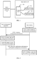
- FIG. 1 shows a communications system 100 applicable to an embodiment of this application.
- the communications system 100 may include an auto-configuration apparatus 110 and at least one base station, for example, a base station 120 shown in FIG. 1 .
- the base station 120 may be a base transceiver station (full name: Base Transceiver Station, BTS for short) in a GSM or CDMA, may be a NodeB (full name: NodeB, NB for short) in WCDMA, or may be an evolved NodeB (full name: evolved NodeB, eNB or e-NodeB for short) in LTE. This is not limited in this embodiment of this application.
- the base station 120 may include a control node 130 and at least one hardware node, for example, a hardware node 140 and a hardware node 150 shown in FIG. 1 . These hardware nodes may be directly connected to the control node 130 by using an optical fiber or a network cable, or may be indirectly connected to the control node 130 by using another hardware node.
- the control node 130 may communicate with each hardware node in the base station.
- the control node 130 may be a baseband unit (English: Baseband Unit, BBU for short).
- the hardware node may be an RRU or a HUB, and the HUB may be a router or a hub.
- the base station 120 may include one or more RRUs, the RRUs may be directly connected to the control node, or may be connected to the control node by using a HUB, and the RRUs may be cascaded.
- the auto-configuration apparatus 110 may perform physical configuration and logical configuration on the control node and the hardware node included in the base station.
- the physical configuration is mainly used to configure hardware attributes of the control node and the hardware node, and a topology relationship between the control node and the hardware node.
- the logical configuration is mainly used to bind a hardware resource to a corresponding logical resource.
- the auto-configuration apparatus may be a software program, a hardware module, a combination of a software program and a hardware module, or the like. This is not limited in this embodiment of this application.
- the auto-configuration apparatus may be an operations support subsystem (full name: Operations Support System, OSS for short).
- connection relationship between the control node and the hardware node shown in FIG. 1 a quantity of hardware nodes, and a quantity of base stations are merely an example, and are not intended to limit the protection scope of this embodiment of this application.
- An actual communications system may further include more base stations, or may include more hardware nodes or the like. This is not limited in this embodiment of this application.
- FIG. 2 is a schematic flowchart of an auto-configuration method according to an embodiment of this application, and shows detailed communication steps or operations of the method. However, these steps or operations are merely an example. Other operations or variations of the operations in FIG. 2 may be further performed in this embodiment of this application. In addition, the steps in FIG. 2 may be separately performed in a sequence different from that shown in FIG. 2 , and possibly, not all the operations in FIG. 2 need to be performed.
- FIG. 2 is a schematic flowchart of an auto-configuration method 200, described from a perspective of device interaction, according to an embodiment of this application.
- the method 200 may be applied to the communications system 100 shown in FIG. 1 .
- the method 200 includes the following steps.
- a base station obtains inventory configuration information of the base station, where the base station includes a control node and at least one hardware node, the inventory configuration information of the base station includes inventory configuration information of the at least one hardware node, and inventory configuration information of each hardware node indicates topology information and hardware attribute information of each hardware node.
- the base station includes the control node and the at least one hardware node.
- physical configuration and logical configuration need to be performed on the control node and the at least one hardware node, to properly transmit a service.
- the physical configuration is used to configure topology information and hardware attribute information of the control node and the at least one hardware node.
- the logical configuration is used to configure logical resources that can be used by the control node and the at least one hardware node to transmit a service, that is, logical resources corresponding to the control node and the at least one hardware node.
- the inventory configuration information of the base station needs to be obtained, and the inventory configuration information of the base station includes topology information and hardware attribute information of the at least one hardware node.
- the inventory configuration information of the base station may be used by an auto-configuration apparatus to determine physical configuration information of the base station.
- the physical configuration information of the base station is topology information and hardware attribute information of each node that needs to be configured in the base station.
- Each node that needs to be configured is a node that is determined by the auto-configuration apparatus and that is configured to transmit a service.
- All the nodes that need to be configured may be the at least one hardware node, or may be nodes that are determined by the auto-configuration apparatus in the at least one hardware node based on a user requirement and that need to be configured. In other words, all the nodes that need to be configured may be some or all of the at least one hardware node.
- S210 may further include:
- each hardware node in the base station is indicated by using a relative location.
- the control node may obtain the relative location of each hardware node by successively scanning all hardware nodes, so as to obtain the topology information of each hardware node.
- the topology information and the hardware attribute information of the hardware node in the base station may be obtained by the control node by scanning each hardware node. After the control node obtains the topology information and the hardware attribute information of each hardware node, the control node may further generate topology information and corresponding hardware attribute information of the control node. Therefore, the inventory configuration information of the base station may further include the topology information and the hardware attribute information of the control node. The topology information and the attribute information of the control node may be used by the auto-configuration apparatus to configure a topology relationship and a hardware attribute of the control node.
- the following uses a topology structure shown in FIG. 3 as an example to describe in detail how the base station obtains topology information of nodes shown in FIG. 3 .
- an action of scanning each hardware node may be performed by a control node BBU shown in FIG. 3 .
- the BBU initiates a hardware node scanning process.
- the BBU first finds that an optical port 5 (namely, a PN 5 shown in FIG. 3 ) of the BBU is connected to a HUB 1, then continues to perform scanning downwards from the HUB 1, and determines that the HUB 1 is connected to a HUB 2. Subsequently, the BBU successively performs scanning downwards, and learns that a HUB 3 is connected to the HUB 2.
- an optical port 1 namely, a GePort 1 in FIG. 3
- an optical port 2 namely, a GePort 2 in FIG. 3
- the topology information of each hardware node may be represented by using an attribute of the control node connected to the hardware node, information about a port connected to the hardware node, level information, and the like.
- the attribute of the control node may indicate a specific control node that controls the hardware connection.
- the attribute of the control node may be information about a cabinet number, a subrack number, and a slot ID of the BBU. If the hardware node is an RRU, the information about the port connected to the hardware node may include a port number of a HUB connected to the hardware node. If the hardware node is a HUB, the information about the port connected to the hardware node may include a port number of an RRU connected to the hardware node.
- the topology information of each hardware node in the base station may be represented in a manner shown in Table 1.
- Table 1 CN SRN SN PN mianLevel GePort Hop RHUB 1 0 0 3 5 0 0 0 0 RHUB 2 0 0 3 5 1 0 1 RHUB 3 0 0 3 5 2 0 2 PRRU 1 0 0 3 5 1 1 0 PRRU 2 0 0 3 5 1 2 0
- the CN, SRN, and SR are used to describe the attribute of the control node BBU.
- the CN, SRN, and SR respectively indicate the information about the cabinet number, the subrack number, and the slot ID of the BBU.
- the PN indicates an optical port number, that is, a specific optical port that is of the BBU and to which the hardware node is connected. In other words, information in first four columns is used to describe attribute information of the control node.
- the mianLevel indicates cascading level information
- the GePort indicates an optical port number of a connected HUB
- the HOP indicates a port number of a connected RRU.
- the topology information of the control node and the hardware node in FIG. 3 may be represented in the manner shown in Table 1.
- an identifier of a hardware node in a leftmost column of Table 1 may be an identifier that can uniquely indicate the hardware node.
- information such as a bill of materials (full name: Bill Of Materials, BOM for short) code of the hardware node may be used to identify the hardware node.
- the hardware attribute information of each hardware node may be stored in a storage unit of the hardware node, or may be stored in a storage unit of the control node. If the hardware attribute information of each hardware node is stored in a storage unit of each hardware node, the control node may obtain the hardware attribute information of each hardware node by scanning each hardware node.
- the hardware attribute information of the hardware node may include identifier information of the hardware node, and identifier information of hardware nodes are in a one-to-one correspondence with the hardware nodes. Therefore, a hardware node can be uniquely determined based on identifier information of the hardware node.
- the hardware attribute information of each hardware node may include information such as a module name, a configuration type, a quantity of transmit ports, a quantity of receive ports, an RRU type (full name: RRU Type, RT for short), and an RRU working standard (RS for short).
- the hardware attribute information of each hardware node may be represented in a manner shown in Table 2.
- the identifier information may be BOM code information of the hardware node.
- Different BOM codes may be configured for all hardware nodes to distinguish different hardware nodes, so that the hardware attribute information of each hardware node may be obtained based on the BOM codes.
- other hardware attribute information of the hardware node may be determined based on a BOM code 02310YBS.
- a module name is PRRU 3901
- a configuration type is PRRU
- an RT is MPMU
- an RS is ULFTD. It should be understood that a null part in Table 2 indicates that the hardware node does not have corresponding hardware attribute information.
- the control node in the base station may obtain the topology information and the hardware attribute information of each hardware node by scanning each hardware node. Therefore, the topology information of the hardware node that is obtained by the base station can reflect an actual connection relationship among all hardware nodes, so as to avoid a prior art problem that a configured hardware node cannot properly work because configuration data and an actual connection relationship do not match due to configuration of the hardware node that is performed by using an NMS or a planning drawing.
- the base station sends the inventory configuration information of the base station to an auto-configuration apparatus.
- the auto-configuration apparatus may establish an inventory data channel with the base station. After obtaining the inventory configuration information of the base station, the base station may send the inventory configuration information to the auto-configuration apparatus through the inventory data channel, so that the auto-configuration apparatus can generate the physical configuration information of the base station based on the inventory configuration information of the base station.
- the auto-configuration apparatus determines physical configuration information of the base station, where the base station includes the control node and the at least one hardware node, the physical configuration information of the base station indicates topology information and hardware attribute information of each node that needs to be configured, and all the nodes that need to be configured include some or all of the at least one hardware node.
- all the nodes that need to be configured may include each hardware node included in an actual connection relationship in the base station, or may be nodes that are determined by the auto-configuration apparatus based on a user requirement and that need to be configured. In other words, an actually connected node may not be configured to transmit a service, and therefore, the node may not be configured.
- the auto-configuration apparatus may prestore configuration information of the base station, and the prestored configuration information of the base station may be used to configure a node in the base station.
- the auto-configuration apparatus may determine the prestored configuration information of the base station as the physical configuration information of the base station, and then send the physical configuration information of the base station to the base station, so that the base station performs physical configuration on the node in the base station based on the physical configuration information of the base station.
- S230 may specifically include: determining the physical configuration information of the base station based on the inventory configuration information of the base station.
- the auto-configuration apparatus may determine, based on the inventory configuration information of the base station, the actual connection status, namely, the topology information, of the node included in the base station, so as to update the prestored configuration information of the base station based on the topology information.
- the auto-configuration apparatus may determine, based on a user requirement, a specific node that needs to be configured, and then configure, based on the inventory configuration information of the base station, the node that is determined by a user and that needs to be configured.
- the auto-configuration apparatus may be used by the user to select the node to be configured. Therefore, flexibility of configuration of the base station is further improved.
- the determining the physical configuration information of the base station based on the inventory configuration information of the base station may specifically include:
- the auto-configuration apparatus compares the inventory configuration information of the base station with the prestored configuration information of the base station, and determines the physical configuration information of the base station based on a difference between the inventory configuration information of the base station and the prestored configuration information of the base station. Therefore, consistency between actually installed hardware and the prestored configuration information can be ensured.
- the inventory configuration information of the base station includes the inventory configuration information of the first hardware node, but the prestored configuration information of the base station includes no configuration information of the first hardware node, the configuration information of the first hardware node is newly added to the prestored configuration information of the base station, and the newly added configuration information of the first hardware node may be determined based on the inventory configuration information of the first hardware node that is included in the inventory configuration information of the base station.
- the auto-configuration apparatus may notify the user that the configuration information of the second hardware node is inconsistent with the inventory configuration information, so that the user selects specific configuration information, and configures the second hardware node based on the configuration information.
- the auto-configuration apparatus may directly determine to configure the second hardware node based on the inventory configuration information of the second hardware node that is reported by the base station, to be specific, determine the inventory configuration information of the second hardware node as the configuration information of the second hardware node in the prestored configuration information of the base station, in other words, update the configuration information of the second hardware node in the prestored configuration information of the base station by using the inventory configuration information of the second hardware node.
- the auto-configuration apparatus may notify the user that the actual connection relationship includes no third hardware node, so that the user chooses to delete or keep the configuration information of the third hardware node, or the auto-configuration apparatus may directly determine to delete the configuration information of the third hardware node in the prestored configuration information of the base station.
- the auto-configuration apparatus may determine to keep the configuration information of the fourth hardware node.
- the auto-configuration apparatus determines the updated prestored configuration information of the base station as the physical configuration information of the base station. Therefore, the physical configuration information of the base station can reflect the actual connection status of the hardware node, thereby avoiding a problem that the base station cannot work because the configuration information and the actual connection status do not match.
- the auto-configuration apparatus determines logical mapping configuration information of the base station, where the logical mapping configuration information of the base station indicates a mapping relationship between a hardware resource included in the base station and a logical resource corresponding to the hardware resource, and the hardware resource includes each node that needs to be configured.
- the hardware resource may be some or all of the at least one hardware node included in the base station.
- the auto-configuration apparatus may determine the logical mapping configuration information of the base station.
- the logical mapping configuration information of the base station indicates the mapping relationship between a hardware resource included in the base station and a logical resource corresponding to the hardware resource, and the logical mapping configuration information of the base station may be used to determine a logical resource that can be used by each node that needs to be configured to transmit a service. Therefore, the auto-configuration apparatus may send the logical mapping configuration information of the base station to the base station, so that the base station can configure, for each node that needs to be configured, the logical resource that can be used by the node to transmit a service.
- S240 may specifically include:
- logical resources of the base station include a cell 0 and a cell 1
- hardware resources of the base station include an RRU 0 to an RRU 5.
- a quantity 6 of hardware resources is greater than a quantity 2 of logical resources, and then the auto-configuration apparatus may establish, according to the hardware resource equal-allocation principle, a mapping relationship shown in Table 3.
- Table 3 Hardware resource RRU0 RRU1 RRU2 RRU3 RRU4 RRU5 Logical resource Cell0 Cell0 Cell 0 Cell 1 Cell 1 Cell 1
- the RRU 0, the RRU 1, and the RRU 2 correspond to the cell 0, and the RRU 3, the RRU 4, and the RRU 5 correspond to the cell 1.
- the auto-configuration apparatus may establish, according to the logical resource equal-allocation principle, a mapping relationship shown in Table 4.
- Table 4 Logical resource Cell 0 Cell 1 Cell 2 Cell 3 Cell 4 Cell 5 Hardware resource RRU 0 RRU 0 RRU 0 RRU 1 RRU 1
- the RRU 0 corresponds to the cell 0, the cell 1, and the cell 2, and the RRU 1 corresponds to the cell 3, the cell 4, and the cell 5.
- the auto-configuration apparatus establishes the mapping relationship according to the hardware resource equal-allocation principle or the logical resource equal-allocation principle is merely an example implementation.
- the mapping relationship may alternatively be established according to another principle.
- the mapping relationship may be established based on a service capability of each RRU, a service volume born by each RRU, or another hardware attribute of each RRU. This is not limited in this embodiment of this application.
- the logical mapping configuration information of the base station may be represented by using a mapping relationship between an equipment serial number of each node that needs to be configured and a logical resource corresponding to each node that needs to be configured, and all the nodes that need to be configured are in a one-to-one correspondence with the equipment serial numbers of all the nodes that need to be configured.
- the auto-configuration apparatus determines the mapping relationship based on an equipment serial number of each hardware node that needs to be configured is described below with reference to a specific embodiment.
- the auto-configuration apparatus may establish a mapping relationship between an equipment serial number of a hardware resource and a logical resource based on the equipment serial number of the hardware node, so as to uniquely determine, based on the equipment serial number in the mapping relationship, a logical resource corresponding to the hardware node.
- each hardware node may be represented in a manner shown in Table 5.
- Table 5 RRU name RRU 101 RRU 102 RRU 103 RRU 104 RRU 105 RRU 106 Equipment serial number ESN 222 ESN 223 ESN 224 ESN 225 ESN 226 ESN 227
- the auto-configuration apparatus may establish a mapping relationship shown in Table 6 that is between a hardware resource and a logical resource, namely, the logical mapping configuration relationship.
- Table 6 Equipment serial number ESN 222 ESN 223 ESN 224 ESN 225 ESN 226 ESN 227 Cell number Cell 1 Cell 1 Cell 1 Cell 2 Cell 2 Cell 2
- the base station can determine, based on an equipment serial number, a logical resource corresponding to a hardware resource identified by the equipment serial number. For example, if an equipment serial number of a hardware resource is ESN 225, it may be determined that a logical resource corresponding to an RRU 104 identified by ESN 225 is a cell 2.
- the auto-configuration apparatus may alternatively establish the mapping relationship based on other indication information that can uniquely identify a hardware resource. This is not limited in this embodiment of this application.
- the auto-configuration apparatus sends the physical configuration information of the base station and the logical mapping configuration information of the base station to the base station.
- the base station configures, based on the physical configuration information of the base station and the logical mapping configuration information of the base station, each node that needs to be configured.
- the auto-configuration apparatus may send the physical configuration information of the base station and the logical mapping configuration information of the base station to the base station, so that the base station can configure, based on the physical configuration information of the base station and the logical mapping configuration information of the base station, each node that needs to be configured.
- the base station can configure, based on the physical configuration information of the base station and the logical mapping configuration information of the base station, each node that needs to be configured.
- topology information, hardware attribute information, and a corresponding logical resource of each node that needs to be configured may be configured, so that each node that needs to be configured can transmit a service on the corresponding logical resource.
- the base station may report the inventory configuration information of the base station to the auto-configuration apparatus, so that the auto-configuration apparatus may determine the physical configuration information of the base station and the logical mapping configuration information of the base station based on the inventory configuration information of the base station, and then send the determined physical configuration information and logical mapping configuration information of the base station to the base station.
- the base station can configure, based on the physical configuration information and the logical mapping configuration information of the base station, each node that needs to be configured. Therefore, the control node and each hardware node included in the base station do not need to be manually configured one by one, so that configuration duration of the base station can be shortened.
- the method 200 may further include:
- the control node in the base station may determine, by periodically scanning each hardware node, whether physical configuration information of a hardware node included in the base station changes. In the following cases, the control node may determine that the physical configuration information of the at least one hardware node changes, for example, a case in which an RRU is newly added, a case in which an RRU is deleted, or a case in which a port connected to an RRU changes.
- the base station sends the configuration change information to the auto-configuration apparatus, and the configuration change information may indicate that the physical configuration information of the hardware node included in the base station changes.
- the configuration change information may further include specific change information, for example, information indicating that an RRU 102 is newly added, and information indicating that a port connected to an RRU 103 is switched from a port 2 to a port 5.
- the auto-configuration apparatus may determine the incremental configuration information of the base station based on the configuration change information. Changed physical configuration information is not used to reconfigure all hardware nodes after the changed physical configuration information is generated. Instead, the incremental configuration information of the base station is used by the base station to configure only a changed hardware node. Therefore, when physical configuration information of some nodes in the base station changes, configuration duration of the base station can be shortened according to the auto-configuration method in this embodiment of this application.
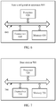
- FIG. 4 is a schematic block diagram of an auto-configuration apparatus 400 according to an embodiment of this application.
- the auto-configuration apparatus 400 includes a processing unit 410 and a sending unit 420.
- the processing unit 410 may be configured to determine physical configuration information of a base station, where the base station includes a control node and at least one hardware node, the physical configuration information of the base station indicates topology information and hardware attribute information of each node that needs to be configured, and all the nodes that need to be configured include some or all of the at least one hardware node.
- the processing unit 410 may be further configured to determine logical mapping configuration information of the base station, where the logical mapping configuration information of the base station indicates a mapping relationship between a hardware resource included in the base station and a logical resource corresponding to the hardware resource, and the hardware resource includes each node that needs to be configured.
- the sending unit 420 is configured to send the physical configuration information of the base station and the logical mapping configuration information of the base station to the base station, so that the base station configures, based on the physical configuration information of the base station and the logical mapping configuration information of the base station, each node that needs to be configured.
- the auto-configuration apparatus 400 may correspond to the auto-configuration apparatus in the auto-configuration method 200 according to the embodiment of this application, and the auto-configuration apparatus 400 may include units configured to perform a method performed by the auto-configuration apparatus in the method 200 in FIG. 2 .
- the units in the auto-configuration apparatus 400 and the foregoing other operations and/or functions are separately intended to implement corresponding procedures of the method 200 in FIG. 2 . For brevity, details are not described herein again.
- FIG. 5 is a schematic block diagram of a base station 500 according to an embodiment of this application.
- the base station 500 includes a processing unit 510, a sending unit 520, and a receiving unit 530.
- the processing unit 510 may be configured to obtain inventory configuration information of the base station, where the base station includes a control node and at least one hardware node, the inventory configuration information of the base station includes inventory configuration information of the at least one hardware node, and inventory configuration information of each hardware node indicates topology information and hardware attribute information of each hardware node.
- the sending unit 520 may be configured to send the inventory configuration information of the base station to an auto-configuration apparatus, where the inventory configuration information of the base station is used to determine physical configuration information of the base station, the physical configuration information of the base station indicates topology information and hardware attribute information of each node that needs to be configured, and all the nodes that need to be configured include some or all of the at least one hardware node.
- the receiving unit 530 may be configured to receive the physical configuration information of the base station and logical mapping configuration information of the base station that are sent by the auto-configuration apparatus, where the logical mapping configuration information of the base station indicates a mapping relationship between a hardware resource included in the base station and a logical resource corresponding to the hardware resource, and the hardware resource includes each node that needs to be configured.
- the processing unit 510 is further configured to configure, based on the physical configuration information of the base station and the logical mapping configuration information of the base station, each node that needs to be configured.
- the base station 500 may correspond to the base station in the auto-configuration method 200 according to the embodiment of this application, and the base station 500 may include units configured to perform a method performed by the base station in the method 200 in FIG. 2 .
- the units in the base station 500 and the foregoing other operations and/or functions are separately intended to implement corresponding procedures of the method 200 in FIG. 2 . For brevity, details are not described herein again.
- FIG. 6 is a schematic block diagram of an auto-configuration apparatus 600 according to another embodiment of this application.
- the auto-configuration apparatus 600 includes a transceiver 610, a processor 620, a memory 630, and a bus system 640.
- the transceiver 610, the processor 620, and the memory 630 are connected by using the bus system 640, the memory 630 is configured to store an instruction, and the processor 620 is configured to execute the instruction stored in the memory 630, so as to control the transceiver 610 to receive or send a signal.
- the memory 630 may be disposed in the processor 620, or may be independent of the processor 620.
- the auto-configuration apparatus 600 may correspond to the auto-configuration apparatus in the auto-configuration method 200 according to the embodiment of this application, and the auto-configuration apparatus 600 may include entity units configured to perform a method performed by the auto-configuration apparatus in the method 200 in FIG. 2 .
- the entity units in the auto-configuration apparatus 600 and the foregoing other operations and/or functions are separately intended to implement corresponding procedures of the method 200 in FIG. 2 . For brevity, details are not described herein again.
- FIG. 7 is a schematic block diagram of a base station 700 according to another embodiment of this application.
- the base station 700 includes a transceiver 710, a processor 720, a memory 730, and a bus system 740.
- the transceiver 710, the processor 720, and the memory 730 are connected by using the bus system 740, the memory 730 is configured to store an instruction, and the processor 720 is configured to execute the instruction stored in the memory 730, so as to control the transceiver 710 to receive or send a signal.
- the memory 730 may be disposed in the processor 720, or may be independent of the processor 720.
- the base station 700 may correspond to the base station in the auto-configuration method 200 according to the embodiment of this application, and the base station 700 may include entity units configured to perform a method performed by the base station in the method 200 in FIG. 2 .
- the entity units in the base station 700 and the foregoing other operations and/or functions are separately intended to implement corresponding procedures of the method 200 in FIG. 2 . For brevity, details are not described herein again.
- processor in the embodiments of this application may be an integrated circuit chip, and has a signal processing capability.
- steps in the foregoing method embodiment can be implemented by using a hardware integrated logical circuit in the processor, or by using instructions in a form of software.
- the foregoing processor may be a central processing unit (Central Processing Unit, "CPU” for short), or the processor may be another general purpose processor, a digital signal processor (Digital Signal Processor, “DSP” for short), an application-specific integrated circuit (Application-Specific Integrated Circuit, "ASIC” for short), a field programmable gate array (Field Programmable Gate Array, "FPGA” for short) or another programmable logic device, a discrete gate or a transistor logic device, or a discrete hardware component. It may implement or perform the method, the steps, and logical block diagrams that are disclosed in the embodiments of this application.
- the general purpose processor may be a microprocessor, or the processor may be any conventional processor or the like.
- Steps of the method disclosed with reference to the embodiments of this application may be directly performed and accomplished by a hardware decoding processor, or may be performed and accomplished by using a combination of hardware and a software unit in the decoding processor.
- the software unit may be located in a mature storage medium in the art, such as a random access memory, a flash memory, a read-only memory, a programmable read-only memory, an electrically erasable programmable memory, or a register.
- the storage medium is located in the memory, and the processor reads information in the memory and completes the steps in the foregoing method in combination with hardware of the processor.
- the memory in the embodiments of this application may be a volatile memory or a nonvolatile memory, or may include a volatile memory and a nonvolatile memory.
- the nonvolatile memory may be a read-only memory (Read-Only Memory, "ROM” for short), a programmable read-only memory (Programmable ROM, “PROM” for short), an erasable programmable read-only memory (Erasable PROM, "EPROM” for short), an electrically erasable programmable read-only memory (Electrically EPROM, "EEPROM” for short), or a flash memory.
- the volatile memory may be a random access memory (Random Access Memory, "RAM” for short), and the volatile memory is used as an external cache.
- RAMs are available, for example, a static random access memory (Static RAM, "SRAM” for short), a dynamic random access memory (Dynamic RAM, “DRAM” for short), a synchronous dynamic random access memory (Synchronous DRAM, “SDRAM” for short), a double data rate synchronous dynamic random access memory (Double Data Rate SDRAM, "DDR SDRAM” for short), an enhanced synchronous dynamic random access memory (Enhanced SDRAM, "ESDRAM” for short), a synchlink dynamic random access memory (Synchlink DRAM, "SLDRAM” for short), and a direct rambus random access memory (Direct Rambus RAM, "DR RAM” for short).
- SRAM static random access memory
- DRAM dynamic random access memory
- DRAM synchronous dynamic random access memory
- SDRAM synchronous dynamic random access memory
- Enhanced SDRAM Enhanced SDRAM
- Enhanced SDRAM synchlink dynamic random access memory
- Synchlink DRAM synchlink DRAM
- SLDRAM direct rambus random access memory
- the bus system may further include a power bus, a control bus, a status signal bus, and the like, in addition to a data bus.
- a power bus may further include a power bus, a control bus, a status signal bus, and the like, in addition to a data bus.
- various types of buses in the figure are marked as the bus system.
- steps in the foregoing method can be implemented by using a hardware integrated logical circuit in the processor, or by using instructions in a form of software.
- the steps of the auto-configuration method disclosed with reference to the embodiments of this application may be directly performed and accomplished by a hardware processor, or may be performed and accomplished by using a combination of hardware and a software unit in the processor.
- the software unit may be located in a mature storage medium in the art, such as a random access memory, a flash memory, a read-only memory, a programmable read-only memory, an electrically erasable programmable memory, or a register.
- the storage medium is located in the memory, and the processor reads information in the memory and completes the steps in the foregoing method in combination with hardware of the processor. To avoid repetition, details are not described herein.
- An embodiment of this application further provides a computer-readable storage medium.
- the computer-readable storage medium stores one or more programs, and the one or more programs include an instruction.
- the instruction When being executed by a portable electronic device including a plurality of application programs, the instruction enables the portable electronic device to perform the method in the embodiment shown in FIG. 2 .
- sequence numbers of the foregoing processes do not mean execution sequences in various embodiments of this application.
- the execution sequences of the processes should be determined according to functions and internal logic of the processes, and should not be construed as any limitation on the implementation processes of the embodiments of this application.
- the disclosed system, apparatus, and method may be implemented in other manners.
- the described apparatus embodiment is merely an example.
- the unit division is merely logical function division and may be other division in actual implementation.
- a plurality of units or components may be combined or integrated into another system, or some features may be ignored or not performed.
- the displayed or discussed mutual couplings or direct couplings or communication connections may be implemented by using some interfaces.
- the indirect couplings or communication connections between the apparatuses or units may be implemented in electronic, mechanical, or other forms.
- the units described as separate parts may or may not be physically separate, and parts displayed as units may or may not be physical units, may be located in one position, or may be distributed on a plurality of network units. Some or all of the units may be selected based on actual requirements to achieve the objectives of the solutions of the embodiments.
- the functions When the functions are implemented in the form of a software functional unit and sold or used as an independent product, the functions may be stored in a computer-readable storage medium. Based on such an understanding, the technical solutions of this application essentially, or the part contributing to the prior art, or some of the technical solutions may be implemented in a form of a software product.
- the computer software product is stored in a storage medium, and includes several instructions for instructing a computer device (which may be a personal computer, a server, or a network device) to perform all or some of the steps of the method described in the embodiments of this application.
- the foregoing storage medium includes: any medium that can store program code, such as a USB flash drive, a removable hard disk, a read-only memory (ROM, Read-Only Memory), a random access memory (RAM, Random Access Memory), a magnetic disk, or an optical disc.
- program code such as a USB flash drive, a removable hard disk, a read-only memory (ROM, Read-Only Memory), a random access memory (RAM, Random Access Memory), a magnetic disk, or an optical disc.
Landscapes
- Engineering & Computer Science (AREA)
- Computer Networks & Wireless Communication (AREA)
- Signal Processing (AREA)
- Automation & Control Theory (AREA)
- Mobile Radio Communication Systems (AREA)
Applications Claiming Priority (1)
| Application Number | Priority Date | Filing Date | Title |
|---|---|---|---|
| PCT/CN2016/107465 WO2018094726A1 (zh) | 2016-11-28 | 2016-11-28 | 自动配置的方法、装置和基站 |
Publications (3)
| Publication Number | Publication Date |
|---|---|
| EP3537751A1 true EP3537751A1 (de) | 2019-09-11 |
| EP3537751A4 EP3537751A4 (de) | 2019-11-20 |
| EP3537751B1 EP3537751B1 (de) | 2022-07-20 |
Family
ID=62194601
Family Applications (1)
| Application Number | Title | Priority Date | Filing Date |
|---|---|---|---|
| EP16922291.6A Active EP3537751B1 (de) | 2016-11-28 | 2016-11-28 | Verfahren und vorrichtung zur automatischen konfiguration und basisstation |
Country Status (5)
| Country | Link |
|---|---|
| US (1) | US11201786B2 (de) |
| EP (1) | EP3537751B1 (de) |
| CN (1) | CN109906628B (de) |
| CA (1) | CA3045198C (de) |
| WO (1) | WO2018094726A1 (de) |
Cited By (1)
| Publication number | Priority date | Publication date | Assignee | Title |
|---|---|---|---|---|
| US20230188414A1 (en) * | 2021-12-14 | 2023-06-15 | Nokia Solutions And Networks Oy | Data center management based on merging/unmerging of configurations |
Families Citing this family (9)
| Publication number | Priority date | Publication date | Assignee | Title |
|---|---|---|---|---|
| CN112351437B (zh) * | 2020-09-30 | 2021-12-24 | 联想(北京)有限公司 | 一种前传网络的数据处理方法和装置 |
| EP4231551A4 (de) * | 2020-10-14 | 2024-07-10 | Rakuten Symphony Singapore Pte. Ltd. | Computersystem und einstellverfahren |
| CN115226111A (zh) * | 2021-04-16 | 2022-10-21 | 大唐移动通信设备有限公司 | 一种网络设备配置方法及其装置 |
| CN115314111B (zh) * | 2021-05-08 | 2024-07-26 | 深圳华臻信息技术有限公司 | 一种拓扑结构生成方法、系统、计算机设备和存储介质 |
| CN113542021A (zh) * | 2021-07-05 | 2021-10-22 | 四川创智联恒科技有限公司 | 一种射频合路连接rru的自动配置方法 |
| CN116208972B (zh) * | 2021-12-01 | 2025-06-10 | 大唐移动通信设备有限公司 | 信号处理方法、装置、设备以及存储介质 |
| CN117290278B (zh) * | 2023-10-10 | 2024-11-19 | 合芯科技有限公司 | 芯片内硬件互联结构、芯片、服务器及方法 |
| US20250247285A1 (en) * | 2024-01-26 | 2025-07-31 | T-Mobile Usa, Inc. | Cellular site reset tool based on alarms or user input file |
| CN120434656A (zh) * | 2024-02-04 | 2025-08-05 | 华为技术有限公司 | 一种装置配置方法、通信装置以及系统 |
Family Cites Families (18)
| Publication number | Priority date | Publication date | Assignee | Title |
|---|---|---|---|---|
| FI980024L (fi) | 1998-01-07 | 1999-07-08 | Nokia Networks Oy | Solukkoradiojärjestelmä ja menetelmä tukiaseman yhdistämiseksi solukko radiojärjestelmään |
| DE202005021930U1 (de) * | 2005-08-01 | 2011-08-08 | Corning Cable Systems Llc | Faseroptische Auskoppelkabel und vorverbundene Baugruppen mit Toning-Teilen |
| CN101064860B (zh) * | 2006-04-29 | 2012-04-11 | 中兴通讯股份有限公司 | 蜂窝移动通信系统无线参数自动配置方法 |
| CN101166039B (zh) * | 2006-10-17 | 2012-07-11 | 中兴通讯股份有限公司 | 一种无线通信系统中远端射频单元自动发现的方法 |
| TWI481263B (zh) * | 2006-10-20 | 2015-04-11 | Interdigital Tech Corp | Lte增強b節點自行配置方法及裝置 |
| CN101094144A (zh) * | 2007-07-26 | 2007-12-26 | 华为技术有限公司 | 无线接入网的数据配置方法和系统 |
| WO2009094796A1 (fr) | 2008-01-22 | 2009-08-06 | Zte Corporation | Système et procédé pour une station de base exécutant automatiquement une configuration |
| ES2724150T3 (es) | 2008-12-18 | 2019-09-06 | Orange | Procedimiento y dispositivo de configuración de una pluralidad de puntos de acceso de una red local celular |
| CN101932143B (zh) * | 2009-06-18 | 2013-11-20 | 中兴通讯股份有限公司南京分公司 | 一种演进射频拉远单元启动自配置的方法 |
| US20130331114A1 (en) * | 2012-06-06 | 2013-12-12 | Eden Rock Communications, Llc | Adjacent network aware self organizing network system |
| CN103687088B (zh) * | 2012-09-03 | 2018-09-11 | 南京中兴软件有限责任公司 | 一种射频拉远单元自动配置的方法、系统和装置 |
| CN103297985B (zh) * | 2013-05-31 | 2016-01-27 | 华为技术有限公司 | 基站配置方法及系统 |
| CN103974287B (zh) * | 2014-04-22 | 2017-08-29 | 深圳三星通信技术研究有限公司 | 一种进行拓扑扫描的方法、基站以及bbu和rru |
| US9680695B2 (en) * | 2014-10-24 | 2017-06-13 | At&T Intellectual Property I, L.P. | Facilitating mobility dimensioning via dynamic configuration of a switch |
| US20160218912A1 (en) * | 2015-01-27 | 2016-07-28 | Nokia Solutions And Networks Oy | Quality of experience aware transport self organizing network framework |
| CN106162664B (zh) * | 2015-03-26 | 2019-07-26 | 鼎桥通信技术有限公司 | 一种基站配置信息的生成方法和系统 |
| CN107873126B (zh) * | 2015-04-15 | 2021-02-05 | 诺基亚通信公司 | 用于小小区回程的自组织网络概念 |
| WO2017070635A1 (en) * | 2015-10-22 | 2017-04-27 | Phluido, Inc. | Virtualization and orchestration of a radio access network |
-
2016
- 2016-11-28 EP EP16922291.6A patent/EP3537751B1/de active Active
- 2016-11-28 CN CN201680090623.XA patent/CN109906628B/zh active Active
- 2016-11-28 WO PCT/CN2016/107465 patent/WO2018094726A1/zh not_active Ceased
- 2016-11-28 CA CA3045198A patent/CA3045198C/en active Active
-
2019
- 2019-05-24 US US16/422,379 patent/US11201786B2/en active Active
Cited By (3)
| Publication number | Priority date | Publication date | Assignee | Title |
|---|---|---|---|---|
| US20230188414A1 (en) * | 2021-12-14 | 2023-06-15 | Nokia Solutions And Networks Oy | Data center management based on merging/unmerging of configurations |
| EP4199451A1 (de) * | 2021-12-14 | 2023-06-21 | Nokia Solutions and Networks Oy | Datenzentrumsverwaltung auf der basis des zusammenführens/lösens von konfigurationen |
| US12126492B2 (en) * | 2021-12-14 | 2024-10-22 | Nokia Solutions And Networks Oy | Data center management based on merging/unmerging of configurations |
Also Published As
| Publication number | Publication date |
|---|---|
| WO2018094726A1 (zh) | 2018-05-31 |
| US11201786B2 (en) | 2021-12-14 |
| US20190280928A1 (en) | 2019-09-12 |
| CA3045198C (en) | 2023-06-13 |
| CA3045198A1 (en) | 2018-05-31 |
| EP3537751B1 (de) | 2022-07-20 |
| CN109906628B (zh) | 2020-12-15 |
| CN109906628A (zh) | 2019-06-18 |
| EP3537751A4 (de) | 2019-11-20 |
Similar Documents
| Publication | Publication Date | Title |
|---|---|---|
| US11201786B2 (en) | Auto-configuration method and apparatus, and base station | |
| US11191076B2 (en) | Transmission configuration method and related product | |
| EP3416425B1 (de) | Verfahren, vorrichtung und drahtloskommunikationssystem zur bestimmung eines steuerungsebenenknotens | |
| EP3611948A1 (de) | Kommunikationsverfahren und zugehörige vorrichtung | |
| EP3664516B1 (de) | Verfahren und vorrichtung zur steuerung der eingeschränkten ue-fähigkeit und computerspeichermedium | |
| US11234175B2 (en) | Method for selecting cell, terminal device, and network device | |
| US10368276B2 (en) | Cell handover method, base station, and control node | |
| EP3373648A1 (de) | Wegverarbeitungsverfahren, vorrichtung und endgerät | |
| US12185121B2 (en) | Communication method and communication apparatus | |
| US20240195482A1 (en) | Machine Learning-Based Beam Selection | |
| KR102642804B1 (ko) | 다중 대역 통신 방법 및 장치 | |
| US20190110212A1 (en) | Method, apparatus, terminal and base station for wireless communication | |
| EP3154298B1 (de) | Interferenzkoordinationsverfahren und basisstation | |
| EP3592016A1 (de) | Verfahren und vorrichtung zur auswahl einer kernnetzwerkvorrichtung | |
| US10136430B2 (en) | Data transmission using frequency resources determined from frequency resource numbers | |
| CN115051918A (zh) | 网络设备的控制方法、服务器、装置及存储介质 | |
| HK40003981A (en) | Method and device for automatic configuration, and base station | |
| HK40003981B (zh) | 自动配置的方法、装置和基站 | |
| CN114765878B (zh) | 上行传输、配置方法及装置、存储介质、终端、网络侧设备 | |
| US20230413223A1 (en) | Positioning method and apparatus | |
| CN111601346B (zh) | 接入小区确定、信息配置方法和设备 | |
| CN110972146B (zh) | 无线网络的配置方法及网络设备 | |
| EP3531769A1 (de) | Informationsübertragungsverfahren und zugriffsnetzwerkvorrichtung |
Legal Events
| Date | Code | Title | Description |
|---|---|---|---|
| STAA | Information on the status of an ep patent application or granted ep patent |
Free format text: STATUS: THE INTERNATIONAL PUBLICATION HAS BEEN MADE |
|
| PUAI | Public reference made under article 153(3) epc to a published international application that has entered the european phase |
Free format text: ORIGINAL CODE: 0009012 |
|
| STAA | Information on the status of an ep patent application or granted ep patent |
Free format text: STATUS: REQUEST FOR EXAMINATION WAS MADE |
|
| 17P | Request for examination filed |
Effective date: 20190607 |
|
| AK | Designated contracting states |
Kind code of ref document: A1 Designated state(s): AL AT BE BG CH CY CZ DE DK EE ES FI FR GB GR HR HU IE IS IT LI LT LU LV MC MK MT NL NO PL PT RO RS SE SI SK SM TR |
|
| AX | Request for extension of the european patent |
Extension state: BA ME |
|
| A4 | Supplementary search report drawn up and despatched |
Effective date: 20191023 |
|
| RIC1 | Information provided on ipc code assigned before grant |
Ipc: H04W 24/02 20090101AFI20191017BHEP Ipc: H04W 88/08 20090101ALN20191017BHEP |
|
| DAV | Request for validation of the european patent (deleted) | ||
| DAX | Request for extension of the european patent (deleted) | ||
| STAA | Information on the status of an ep patent application or granted ep patent |
Free format text: STATUS: EXAMINATION IS IN PROGRESS |
|
| 17Q | First examination report despatched |
Effective date: 20201007 |
|
| REG | Reference to a national code |
Ref country code: DE Ref legal event code: R079 Ref document number: 602016073712 Country of ref document: DE Free format text: PREVIOUS MAIN CLASS: H04W0016180000 Ipc: H04W0024020000 |
|
| RIC1 | Information provided on ipc code assigned before grant |
Ipc: H04W 88/08 20090101ALN20211222BHEP Ipc: H04L 12/24 20060101ALI20211222BHEP Ipc: H04W 24/02 20090101AFI20211222BHEP |
|
| GRAP | Despatch of communication of intention to grant a patent |
Free format text: ORIGINAL CODE: EPIDOSNIGR1 |
|
| STAA | Information on the status of an ep patent application or granted ep patent |
Free format text: STATUS: GRANT OF PATENT IS INTENDED |
|
| RIC1 | Information provided on ipc code assigned before grant |
Ipc: H04W 16/18 20090101ALN20220113BHEP Ipc: H04L 41/0873 20220101ALN20220113BHEP Ipc: H04L 41/0813 20220101ALN20220113BHEP Ipc: H04W 88/08 20090101ALN20220113BHEP Ipc: H04L 41/08 20220101ALI20220113BHEP Ipc: H04L 41/12 20220101ALI20220113BHEP Ipc: H04W 24/02 20090101AFI20220113BHEP |
|
| INTG | Intention to grant announced |
Effective date: 20220204 |
|
| GRAS | Grant fee paid |
Free format text: ORIGINAL CODE: EPIDOSNIGR3 |
|
| GRAA | (expected) grant |
Free format text: ORIGINAL CODE: 0009210 |
|
| STAA | Information on the status of an ep patent application or granted ep patent |
Free format text: STATUS: THE PATENT HAS BEEN GRANTED |
|
| AK | Designated contracting states |
Kind code of ref document: B1 Designated state(s): AL AT BE BG CH CY CZ DE DK EE ES FI FR GB GR HR HU IE IS IT LI LT LU LV MC MK MT NL NO PL PT RO RS SE SI SK SM TR |
|
| REG | Reference to a national code |
Ref country code: CH Ref legal event code: EP |
|
| REG | Reference to a national code |
Ref country code: DE Ref legal event code: R096 Ref document number: 602016073712 Country of ref document: DE |
|
| REG | Reference to a national code |
Ref country code: AT Ref legal event code: REF Ref document number: 1506363 Country of ref document: AT Kind code of ref document: T Effective date: 20220815 |
|
| REG | Reference to a national code |
Ref country code: IE Ref legal event code: FG4D |
|
| REG | Reference to a national code |
Ref country code: LT Ref legal event code: MG9D |
|
| REG | Reference to a national code |
Ref country code: NL Ref legal event code: MP Effective date: 20220720 |
|
| PG25 | Lapsed in a contracting state [announced via postgrant information from national office to epo] |
Ref country code: SE Free format text: LAPSE BECAUSE OF FAILURE TO SUBMIT A TRANSLATION OF THE DESCRIPTION OR TO PAY THE FEE WITHIN THE PRESCRIBED TIME-LIMIT Effective date: 20220720 Ref country code: RS Free format text: LAPSE BECAUSE OF FAILURE TO SUBMIT A TRANSLATION OF THE DESCRIPTION OR TO PAY THE FEE WITHIN THE PRESCRIBED TIME-LIMIT Effective date: 20220720 Ref country code: PT Free format text: LAPSE BECAUSE OF FAILURE TO SUBMIT A TRANSLATION OF THE DESCRIPTION OR TO PAY THE FEE WITHIN THE PRESCRIBED TIME-LIMIT Effective date: 20221121 Ref country code: NO Free format text: LAPSE BECAUSE OF FAILURE TO SUBMIT A TRANSLATION OF THE DESCRIPTION OR TO PAY THE FEE WITHIN THE PRESCRIBED TIME-LIMIT Effective date: 20221020 Ref country code: NL Free format text: LAPSE BECAUSE OF FAILURE TO SUBMIT A TRANSLATION OF THE DESCRIPTION OR TO PAY THE FEE WITHIN THE PRESCRIBED TIME-LIMIT Effective date: 20220720 Ref country code: LV Free format text: LAPSE BECAUSE OF FAILURE TO SUBMIT A TRANSLATION OF THE DESCRIPTION OR TO PAY THE FEE WITHIN THE PRESCRIBED TIME-LIMIT Effective date: 20220720 Ref country code: LT Free format text: LAPSE BECAUSE OF FAILURE TO SUBMIT A TRANSLATION OF THE DESCRIPTION OR TO PAY THE FEE WITHIN THE PRESCRIBED TIME-LIMIT Effective date: 20220720 Ref country code: FI Free format text: LAPSE BECAUSE OF FAILURE TO SUBMIT A TRANSLATION OF THE DESCRIPTION OR TO PAY THE FEE WITHIN THE PRESCRIBED TIME-LIMIT Effective date: 20220720 Ref country code: ES Free format text: LAPSE BECAUSE OF FAILURE TO SUBMIT A TRANSLATION OF THE DESCRIPTION OR TO PAY THE FEE WITHIN THE PRESCRIBED TIME-LIMIT Effective date: 20220720 |
|
| REG | Reference to a national code |
Ref country code: AT Ref legal event code: MK05 Ref document number: 1506363 Country of ref document: AT Kind code of ref document: T Effective date: 20220720 |
|
| PG25 | Lapsed in a contracting state [announced via postgrant information from national office to epo] |
Ref country code: PL Free format text: LAPSE BECAUSE OF FAILURE TO SUBMIT A TRANSLATION OF THE DESCRIPTION OR TO PAY THE FEE WITHIN THE PRESCRIBED TIME-LIMIT Effective date: 20220720 Ref country code: IS Free format text: LAPSE BECAUSE OF FAILURE TO SUBMIT A TRANSLATION OF THE DESCRIPTION OR TO PAY THE FEE WITHIN THE PRESCRIBED TIME-LIMIT Effective date: 20221120 Ref country code: HR Free format text: LAPSE BECAUSE OF FAILURE TO SUBMIT A TRANSLATION OF THE DESCRIPTION OR TO PAY THE FEE WITHIN THE PRESCRIBED TIME-LIMIT Effective date: 20220720 Ref country code: GR Free format text: LAPSE BECAUSE OF FAILURE TO SUBMIT A TRANSLATION OF THE DESCRIPTION OR TO PAY THE FEE WITHIN THE PRESCRIBED TIME-LIMIT Effective date: 20221021 |
|
| REG | Reference to a national code |
Ref country code: DE Ref legal event code: R097 Ref document number: 602016073712 Country of ref document: DE |
|
| PG25 | Lapsed in a contracting state [announced via postgrant information from national office to epo] |
Ref country code: SM Free format text: LAPSE BECAUSE OF FAILURE TO SUBMIT A TRANSLATION OF THE DESCRIPTION OR TO PAY THE FEE WITHIN THE PRESCRIBED TIME-LIMIT Effective date: 20220720 Ref country code: RO Free format text: LAPSE BECAUSE OF FAILURE TO SUBMIT A TRANSLATION OF THE DESCRIPTION OR TO PAY THE FEE WITHIN THE PRESCRIBED TIME-LIMIT Effective date: 20220720 Ref country code: DK Free format text: LAPSE BECAUSE OF FAILURE TO SUBMIT A TRANSLATION OF THE DESCRIPTION OR TO PAY THE FEE WITHIN THE PRESCRIBED TIME-LIMIT Effective date: 20220720 Ref country code: CZ Free format text: LAPSE BECAUSE OF FAILURE TO SUBMIT A TRANSLATION OF THE DESCRIPTION OR TO PAY THE FEE WITHIN THE PRESCRIBED TIME-LIMIT Effective date: 20220720 Ref country code: AT Free format text: LAPSE BECAUSE OF FAILURE TO SUBMIT A TRANSLATION OF THE DESCRIPTION OR TO PAY THE FEE WITHIN THE PRESCRIBED TIME-LIMIT Effective date: 20220720 |
|
| PLBE | No opposition filed within time limit |
Free format text: ORIGINAL CODE: 0009261 |
|
| STAA | Information on the status of an ep patent application or granted ep patent |
Free format text: STATUS: NO OPPOSITION FILED WITHIN TIME LIMIT |
|
| PG25 | Lapsed in a contracting state [announced via postgrant information from national office to epo] |
Ref country code: SK Free format text: LAPSE BECAUSE OF FAILURE TO SUBMIT A TRANSLATION OF THE DESCRIPTION OR TO PAY THE FEE WITHIN THE PRESCRIBED TIME-LIMIT Effective date: 20220720 Ref country code: EE Free format text: LAPSE BECAUSE OF FAILURE TO SUBMIT A TRANSLATION OF THE DESCRIPTION OR TO PAY THE FEE WITHIN THE PRESCRIBED TIME-LIMIT Effective date: 20220720 |
|
| 26N | No opposition filed |
Effective date: 20230421 |
|
| PG25 | Lapsed in a contracting state [announced via postgrant information from national office to epo] |
Ref country code: MC Free format text: LAPSE BECAUSE OF FAILURE TO SUBMIT A TRANSLATION OF THE DESCRIPTION OR TO PAY THE FEE WITHIN THE PRESCRIBED TIME-LIMIT Effective date: 20220720 Ref country code: AL Free format text: LAPSE BECAUSE OF FAILURE TO SUBMIT A TRANSLATION OF THE DESCRIPTION OR TO PAY THE FEE WITHIN THE PRESCRIBED TIME-LIMIT Effective date: 20220720 |
|
| REG | Reference to a national code |
Ref country code: CH Ref legal event code: PL |
|
| REG | Reference to a national code |
Ref country code: BE Ref legal event code: MM Effective date: 20221130 |
|
| PG25 | Lapsed in a contracting state [announced via postgrant information from national office to epo] |
Ref country code: LI Free format text: LAPSE BECAUSE OF NON-PAYMENT OF DUE FEES Effective date: 20221130 Ref country code: CH Free format text: LAPSE BECAUSE OF NON-PAYMENT OF DUE FEES Effective date: 20221130 |
|
| PG25 | Lapsed in a contracting state [announced via postgrant information from national office to epo] |
Ref country code: SI Free format text: LAPSE BECAUSE OF FAILURE TO SUBMIT A TRANSLATION OF THE DESCRIPTION OR TO PAY THE FEE WITHIN THE PRESCRIBED TIME-LIMIT Effective date: 20220720 Ref country code: LU Free format text: LAPSE BECAUSE OF NON-PAYMENT OF DUE FEES Effective date: 20221128 |
|
| PG25 | Lapsed in a contracting state [announced via postgrant information from national office to epo] |
Ref country code: IE Free format text: LAPSE BECAUSE OF NON-PAYMENT OF DUE FEES Effective date: 20221128 |
|
| PG25 | Lapsed in a contracting state [announced via postgrant information from national office to epo] |
Ref country code: FR Free format text: LAPSE BECAUSE OF NON-PAYMENT OF DUE FEES Effective date: 20221130 Ref country code: BE Free format text: LAPSE BECAUSE OF NON-PAYMENT OF DUE FEES Effective date: 20221130 |
|
| PG25 | Lapsed in a contracting state [announced via postgrant information from national office to epo] |
Ref country code: HU Free format text: LAPSE BECAUSE OF FAILURE TO SUBMIT A TRANSLATION OF THE DESCRIPTION OR TO PAY THE FEE WITHIN THE PRESCRIBED TIME-LIMIT; INVALID AB INITIO Effective date: 20161128 |
|
| PG25 | Lapsed in a contracting state [announced via postgrant information from national office to epo] |
Ref country code: CY Free format text: LAPSE BECAUSE OF FAILURE TO SUBMIT A TRANSLATION OF THE DESCRIPTION OR TO PAY THE FEE WITHIN THE PRESCRIBED TIME-LIMIT Effective date: 20220720 |
|
| PG25 | Lapsed in a contracting state [announced via postgrant information from national office to epo] |
Ref country code: MK Free format text: LAPSE BECAUSE OF FAILURE TO SUBMIT A TRANSLATION OF THE DESCRIPTION OR TO PAY THE FEE WITHIN THE PRESCRIBED TIME-LIMIT Effective date: 20220720 Ref country code: IT Free format text: LAPSE BECAUSE OF FAILURE TO SUBMIT A TRANSLATION OF THE DESCRIPTION OR TO PAY THE FEE WITHIN THE PRESCRIBED TIME-LIMIT Effective date: 20220720 |
|
| PG25 | Lapsed in a contracting state [announced via postgrant information from national office to epo] |
Ref country code: TR Free format text: LAPSE BECAUSE OF FAILURE TO SUBMIT A TRANSLATION OF THE DESCRIPTION OR TO PAY THE FEE WITHIN THE PRESCRIBED TIME-LIMIT Effective date: 20220720 |
|
| PG25 | Lapsed in a contracting state [announced via postgrant information from national office to epo] |
Ref country code: BG Free format text: LAPSE BECAUSE OF FAILURE TO SUBMIT A TRANSLATION OF THE DESCRIPTION OR TO PAY THE FEE WITHIN THE PRESCRIBED TIME-LIMIT Effective date: 20220720 |
|
| PG25 | Lapsed in a contracting state [announced via postgrant information from national office to epo] |
Ref country code: MT Free format text: LAPSE BECAUSE OF FAILURE TO SUBMIT A TRANSLATION OF THE DESCRIPTION OR TO PAY THE FEE WITHIN THE PRESCRIBED TIME-LIMIT Effective date: 20220720 |
|
| PGFP | Annual fee paid to national office [announced via postgrant information from national office to epo] |
Ref country code: GB Payment date: 20250930 Year of fee payment: 10 |
|
| PGFP | Annual fee paid to national office [announced via postgrant information from national office to epo] |
Ref country code: DE Payment date: 20250930 Year of fee payment: 10 |