EP3537416A1 - Raumtemperaturregler für gebäudeheiz- und gebäudekühlsysteme, insbesondere für flächenheiz- und flächenkühlsysteme - Google Patents
Raumtemperaturregler für gebäudeheiz- und gebäudekühlsysteme, insbesondere für flächenheiz- und flächenkühlsysteme Download PDFInfo
- Publication number
- EP3537416A1 EP3537416A1 EP19159369.8A EP19159369A EP3537416A1 EP 3537416 A1 EP3537416 A1 EP 3537416A1 EP 19159369 A EP19159369 A EP 19159369A EP 3537416 A1 EP3537416 A1 EP 3537416A1
- Authority
- EP
- European Patent Office
- Prior art keywords
- room temperature
- individual light
- temperature controller
- shadow mask
- matrix
- Prior art date
- Legal status (The legal status is an assumption and is not a legal conclusion. Google has not performed a legal analysis and makes no representation as to the accuracy of the status listed.)
- Granted
Links
Images
Classifications
-
- G—PHYSICS
- G09—EDUCATION; CRYPTOGRAPHY; DISPLAY; ADVERTISING; SEALS
- G09F—DISPLAYING; ADVERTISING; SIGNS; LABELS OR NAME-PLATES; SEALS
- G09F23/00—Advertising on or in specific articles, e.g. ashtrays, letter-boxes
- G09F23/0058—Advertising on or in specific articles, e.g. ashtrays, letter-boxes on electrical household appliances, e.g. on a dishwasher, a washing machine or a refrigerator
-
- G—PHYSICS
- G09—EDUCATION; CRYPTOGRAPHY; DISPLAY; ADVERTISING; SEALS
- G09F—DISPLAYING; ADVERTISING; SIGNS; LABELS OR NAME-PLATES; SEALS
- G09F9/00—Indicating arrangements for variable information in which the information is built-up on a support by selection or combination of individual elements
- G09F9/30—Indicating arrangements for variable information in which the information is built-up on a support by selection or combination of individual elements in which the desired character or characters are formed by combining individual elements
- G09F9/33—Indicating arrangements for variable information in which the information is built-up on a support by selection or combination of individual elements in which the desired character or characters are formed by combining individual elements being semiconductor devices, e.g. diodes
-
- G—PHYSICS
- G09—EDUCATION; CRYPTOGRAPHY; DISPLAY; ADVERTISING; SEALS
- G09F—DISPLAYING; ADVERTISING; SIGNS; LABELS OR NAME-PLATES; SEALS
- G09F13/00—Illuminated signs; Luminous advertising
- G09F13/20—Illuminated signs; Luminous advertising with luminescent surfaces or parts
- G09F13/22—Illuminated signs; Luminous advertising with luminescent surfaces or parts electroluminescent
- G09F2013/222—Illuminated signs; Luminous advertising with luminescent surfaces or parts electroluminescent with LEDs
Definitions
- the present invention relates to a room temperature controller for building heating and building cooling systems, in particular for surface heating and surface cooling systems, preferably for underfloor heating systems.
- Embodiments of such room temperature regulators are constructed of a housing, the back of which is connected to a wall of the room adjacent thereto, and a board accommodated in the housing, which includes the electronic components of the room controller.
- a board accommodated in the housing which includes the electronic components of the room controller.
- pushbuttons or a rotatable adjustment device may be located on the housing.
- the housing wall facing the room can be transparent or translucent.
- the transparent or translucent housing wall is irradiated by a matrix of individual light sources on the circuit board from the rear side in such a way that the total amount of light emitted by the individual light sources provides the user with relevant information, for example the current room temperature, the set room temperature setpoint or the operating mode the surface heating and / or surface cooling system concerned.
- the irradiated surfaces of the transparent or translucent housing wall thus act as a display surface of the room controller.
- circular recesses are located above the individual light sources.
- the power supply for such room temperature controller can be done externally via led out of the wall and in the housing of the room temperature controller clamped or fixed by screw cable or on the other hand internally by a battery or a battery.
- LEDs light-emitting diodes, light-emitting diodes
- LEDs are used as individual light sources.
- the tapers to be introduced result in only a distance between the individual ones Light points of at least 2 mm and a diameter of the individual light spots of at least 1 mm can be realized. This leads to a blurred display.
- the light in the tapers is scattered by the surrounding, transparent or translucent material.
- the object of the present invention is to provide a room temperature controller for surface heating and / or surface cooling systems which overcomes the disadvantages of the prior art.
- the room temperature controller according to the invention should have a sharper display.
- the effect of light scattering by the transparent or translucent material of the housing wall can be prevented by first passing the light emitted by the individual light sources through a shadow mask whose holes are surrounded by opaque material.
- this is a thin mask, which is in particular a separate component, i.
- the shadow mask is not integrated into the housing or the circuit board of the room temperature controller according to the invention, applied directly to the matrix of the individual light sources and fixed.
- the mask can be made by laser cutting.
- the individual points of light are thus optically separated from each other, because the mask prevents the lateral scattering of the light emitted by the individual light sources.
- a reduction of the distance between the individual points of light up to 1.2 mm and the diameter of the individual points of light can be realized up to 0.5 mm, resulting in a sharper display.
- the present invention is to provide a room temperature controller for surface heating and / or surface cooling systems comprising a housing having a transparent or translucent display surface; and a board accommodated in the housing, on which a matrix of individual light sources is arranged, which are adapted to irradiate the display surface on the back, and which according to the invention is characterized in that a shadow mask is arranged between the matrix of individual light sources and the display surface, that each individual light source of the matrix at least associated with a hole of the shadow mask, wherein at least the holes of the shadow mask are surrounded by an opaque material.
- the term "opaque material" in the context of the present invention refers to the radiation emitted by each individual light source, respectively.
- the individual light sources preferably emit light in the visible wavelength range (approximately 380-780 nm).
- Opacity should mean - based on the respective wavelength - a transmittance of preferably at most about 10%, preferably at most about 5% and more preferably at most about 1%.
- the shadow mask is made entirely of opaque material. This adds to the sharpness of the display.
- a mask made entirely of opaque material is easy to manufacture.
- the shadow mask is arranged such that each individual light source of the matrix is associated with exactly one hole of the shadow mask. This also contributes to the sharpness and brightness of the display. Particularly preferably, a hole of the shadow mask is arranged above each individual light source of the matrix.
- the shadow mask is applied directly to the matrix, preferably glued. By directly applying the mask to the matrix, the sharpness and brightness of the display can be further improved.
- the distance between two individual light sources of the matrix is in the range of 1.2 mm to 1.8 mm, preferably in the range of 1.4 mm to 1.6 mm, preferably about 1.5 mm , By using the mask according to the invention, it is possible to achieve such distances between two individual light sources of the matrix in conventional production methods of the components.
- each individual light source has a diameter in the range of 0.5 mm to 0.9 mm, preferably in the range of 0.6 mm to 0.8 mm, particularly preferably about 0.7 mm.
- the use of the mask according to the invention makes it possible to use individual light sources with such a small diameter in common production methods of the components.
- the individual light sources are designed as individual LEDs. LEDs are cost-effective, easily accessible single light sources with low power consumption.
- the room temperature controller further comprises at least one operating element.
- an operating element can be used to set the room temperature setpoint and the operating mode of the surface heating and / or surface cooling system to be controlled with the room temperature controller according to the invention.
- the control element may be, for example, push buttons and / or rotatable adjustment devices, which are preferably arranged on the housing, in particular in the housing wall containing the display surface.
- the thickness of the mask is preferably in the range of 0.3 mm to 0.8 mm, particularly preferably in the range of 0.4 mm to 0.6 mm.
- a thickness of the mask of about 0.5 mm is particularly advantageous according to the invention.
- the room temperature controller according to the invention and individual parts thereof can be produced, for example, line by line or layer by layer using a line-building or layer-building manufacturing method (eg 3D printing).
- a line-building or layer-building manufacturing method eg 3D printing
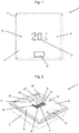
- Fig. 1 shows an embodiment of the room temperature controller 1 according to the invention in a plan view.
- the room thermostat 1 according to the invention comprises a housing 2, which has a transparent or translucent display surface 3.
- the display surface 3 is located in the space facing wall 4 of the housing 2, in the one embodiment the room temperature controller 1 according to the invention is made entirely of translucent material.
- buttons 5, 5 ', 5 " In the wall 4 of the housing 2 are controls 5, 5 ', 5 ", wherein in the in Fig. 1 illustrated embodiment of the room temperature controller 1 according to the invention two operating elements 5, 5 'are formed as touch-sensitive areas of the surface of the wall 4. These are set up to set the room temperature setpoint and are shown as a sign which should indicate the direction of the desired setting change ("plus” stands for setpoint temperature increase and "minus” for setpoint temperature decrease).
- the further operating element 5 " is designed as a touch-sensitive button.
- Fig. 2 shows a perspective view of the in Fig. 1 illustrated room temperature controller 1 according to the invention, wherein the display surface 3 comprising the housing surface is removed. It can be seen that in the housing 1, a circuit board 6 is added.
- the board 6 carries the electronic components of the room temperature controller according to the invention 1.
- On the board 6 is a matrix 7 of individual light sources 8, 8 ', 8 ", 8"', which are formed in the illustrated embodiment as LEDs.
- the individual light sources 8, 8 ', 8 ", 8"' each have a diameter of about 0.7 mm, wherein the decency between two adjacent individual light sources 8, 8 ', 8 ", 8”' is about 1.5 mm.
- a shadow mask 9 is applied directly to the matrix 7.
- the shadow mask 9 is removed from the board 6 and shown raised above this.
- the shadow mask 9 is made entirely of opaque material, here a black-colored plastic material.
- the shadow mask 9 may also be made of metal.
- the shadow mask 9 is arranged on the matrix 7 in such a way that over each individual light source 8, 8 ', 8 ", 8'" of the matrix 7 a hole 10, 10 ', 10 ", 10"' of the shadow mask 9 comes to lie.
- each individual light source 8, 8 ', 8 “, 8'” emits the light emitted by it into the respective hole 10, 10 ', 10 ", 10'” of the shadow mask 9 arranged above it. Since each hole 10, 10 ', 10 ", 10 '” is surrounded by an opaque material, the light is not scattered or emitted to the side, but through the respective hole 10, 10', 10 ", 10 '” to the interior of the housing 2 facing the back of the Room facing wall 4 of the housing 2 passed. The light then passes through the translucent material of the Housing wall 4 and is visible on the display surface 3. Due to the described guidance of the light emitted by the individual light sources 8, 8 ', 8 ", 8", a high sharpness of the display is achieved.
- the individual light sources 8, 8 ', 8 ", 8'" of the matrix 7 can be controlled in such a way that information relevant to the user results from the total light emitted by the individual light sources, for example the current room temperature, the set room temperature setpoint or the operating mode of the surface heating and / or surface cooling system to be controlled.
- the power supply of the room temperature controller 1 according to the invention can on the one hand be done directly via out of the wall and out in the housing 2 of the room temperature controller 1 according to the invention clamped or fixed by screw cable. Alternatively, the power can also be done via a recorded in the housing 2 battery or a corresponding battery.
- a temperature sensor is preferably integrated in the room thermostat 1 according to the invention.
- the room temperature controller 1 can also have a Transmitter or a transmission device which transmits this information or data in the form of electromagnetic waves (eg radio, infrared and the like) to a receiver connected to the actuators of the surface heating and surface cooling system, which sends these to the actuators
- a Transmitter or a transmission device which transmits this information or data in the form of electromagnetic waves (eg radio, infrared and the like) to a receiver connected to the actuators of the surface heating and surface cooling system, which sends these to the actuators
- electromagnetic waves eg radio, infrared and the like
Landscapes
- Physics & Mathematics (AREA)
- General Physics & Mathematics (AREA)
- Engineering & Computer Science (AREA)
- Theoretical Computer Science (AREA)
- Devices For Indicating Variable Information By Combining Individual Elements (AREA)
- Illuminated Signs And Luminous Advertising (AREA)
Abstract
Description
- Die vorliegende Erfindung bezieht sich auf einen Raumtemperaturregler für Gebäudeheiz- und Gebäudekühlsysteme, insbesondere für Flächenheiz- und Flächenkühlsysteme, vorzugsweise für Fußbodenheizungssysteme.
- Derartige Raumtemperaturregler sind im Stand der Technik durch offenkundige Vorbenutzung bekannt. Ausführungsformen derartiger Raumtemperaturregler sind aus einem Gehäuse, dessen Rückseite an einer Wand des Raums anliegend mit dieser verbunden ist, und einer in das Gehäuse aufgenommene Platine, die die elektronischen Komponenten des Raumreglers beinhaltet, aufgebaut. Zur Einstellung des Raumtemperatursollwerts und der Betriebsart des betreffenden Flächenheiz- und/oder Flächenkühlsystems können sich Druckknöpfe oder eine drehbare Einstellungsvorrichtung am Gehäuse befinden. In bekannten Raumreglern kann die dem Raum zugewandte Gehäusewand transparent oder transluzent ausgebildet sein. Die transparente oder transluzente Gehäusewand wird von einer Matrix von Einzellichtquellen auf der Platine von der Rückseite her derart bestrahlt, dass sich aus dem gesamten, von den Einzellichtquellen abgegebenen Licht für den Benutzer relevante Informationen ergeben, beispielsweise zur aktuellen Raumtemperatur, zum eingestellten Raumtemperatursollwert oder zur Betriebsart des betreffenden Flächenheiz- und/oder Flächenkühlsystems. Die bestrahlten Flächen der transparenten oder transluzenten Gehäusewand fungieren dadurch als Anzeigefläche des Raumreglers. Zur Bündelung des von den Einzellichtquellen jeweils abgestrahlten Lichts zur Gehäuseoberfläche hin befinden sich über den Einzellichtquellen kreisrunde Verjüngungen. Die Stromversorgung für derartige Raumtemperaturregler kann einerseits extern über aus der Wand herausgeführte und im Gehäuse des Raumtemperaturreglers klemmend oder durch Verschraubung fixierte Kabel oder anderseits intern durch eine Batterie oder einen Akku erfolgen. Als Einzellichtquellen werden dabei insbesondere LEDs (Light Emitting Diodes, lichemittierende Dioden) eingesetzt.
- Als nachteilig wird an den beschriebenen Raumtemperaturreglern befunden, dass aufgrund der Herstellung der transparenten oder transluzenten Gehäusewand mittels Spritzguss die einzubringenden Verjüngungen dazu führen, dass lediglich ein Abstand zwischen den einzelnen Lichtpunkten von mindestens 2 mm und ein Durchmesser der einzelnen Lichtpunkte von mindestens 1 mm realisiert werden kann. Dies führt zu einer unscharfen Anzeige. Dazu trägt zusätzlich bei, dass das Licht in den Verjüngungen durch das sie umgebende, der transparente oder transluzente Material gestreut wird.
- Vor diesem Hintergrund liegt der vorliegenden Erfindung die Aufgabe zugrunde, einen Raumtemperaturregler für Flächenheiz- und/oder Flächenkühlsysteme zur Verfügung zu stellen, der die Nachteile des Stands der Technik überwindet. Insbesondere soll der erfindungsgemäße Raumtemperaturregler über eine schärfere Anzeige verfügen.
- Diese und andere Aufgaben werden durch einen Raumtemperaturregler mit den Merkmalen des Anspruchs 1 gelöst. Bevorzugte Ausführungsformen des erfindungsgemäßen Raumtemperaturreglers sind in den abhängigen Ansprüchen beschrieben.
- Gemäß der vorliegenden Erfindung wurde erkannt, dass der Effekt der Lichtstreuung durch das transparente oder transluzente Material der Gehäusewand dadurch verhindert werden kann, dass das von den Einzellichtquellen emittierte Licht zunächst durch eine Lochmaske geleitet wird, deren Löcher von lichtundurchlässigem Material umgeben sind. Bevorzugt wird dazu eine dünne Maske, bei der es sich insbesondere um ein separates Bauteil handelt, d.h. die Lochmaske ist nicht in das Gehäuse oder die Platine des erfindungsgemäßen Raumtemperaturreglers integriert, direkt auf die Matrix der Einzellichtquellen aufgebracht und fixiert. Die Maske kann mittels Laserschneiden hergestellt werden. Die einzelnen Lichtpunkte sind somit optisch voneinander getrennt werden, weil die Maske das seitliche Streuen des von den Einzellichtquellen emittierte Lichts verhindert. Durch die Maske lässt sich eine Verringerung des Abstands zwischen den einzelnen Lichtpunkten auf bis zu 1,2 mm und des Durchmessers der einzelnen Lichtpunkte auf bis zu 0,5 mm realisieren, woraus eine schärfere Anzeige resultiert.
- Dementsprechend liegt die vorliegende Erfindung in der Bereitstellung eines Raumtemperaturreglers für Flächenheiz- und/oder Flächenkühlsysteme, der ein Gehäuse mit einer transparenten oder transluzenten Anzeigefläche; und eine in dem Gehäuse aufgenommene Platine, auf der eine Matrix von Einzellichtquellen angeordnet ist, die dazu eingerichtet sind, die Anzeigefläche rückseitig zu bestrahlen, umfasst und erfindungsgemäß dadurch gekennzeichnet ist, dass zwischen der Matrix von Einzellichtquellen und der Anzeigefläche eine Lochmaske derart angeordnet ist, dass jede Einzellichtquelle der Matrix mindestens einem Loch der Lochmaske zugeordnet ist, wobei zumindest die Löcher der Lochmaske von einem lichtundurchlässigem Material umgeben sind.
- Wie hierin verwendet, bezieht sich der Begriff "lichtundurchlässiges Material" im Zusammenhang mit der vorliegenden Erfindung jeweils auf die von der jeweiligen Einzellichtquelle emittierte Strahlung. Dabei emittieren die Einzellichtquellen bevorzugt Licht im sichtbaren Wellenlängenbereich (etwa 380 - 780 nm). Lichtundurchlässigkeit soll dabei - bezogen auf die jeweilige Wellenlänge - einen Transmissionsgrad von vorzugsweise höchstens etwa 10%, bevorzugt höchstens etwa 5% und besonders bevorzugt höchstens etwa 1% bedeuten.
- Dabei kann es von Vorteil sein, wenn die Lochmaske vollständig aus lichtundurchlässigem Material hergestellt ist. Dies trägt zur Schärfe der Anzeige bei. Darüber hinaus ist eine Maske vollständig aus lichtundurchlässigem Material leicht herzustellen.
- Es kann sich auch als günstig erweisen, wenn die Lochmaske derart angeordnet ist, dass jede Einzellichtquelle der Matrix genau einem Loch der Lochmaske zugeordnet ist. Auch das trägt zur Schärfe und zur Helligkeit der Anzeige bei. Besonders bevorzugt ist über jeder Einzellichtquelle der Matrix ein Loch der Lochmaske angeordnet.
- Ebenso kann es von Nutzen sein, wenn die Lochmaske direkt auf die Matrix aufgebracht, vorzugsweise aufgeklebt ist. Durch direktes Aufbringen der Maske auf die Matrix lassen sich die Schärfe und zur Helligkeit der Anzeige weiter verbessern.
- Es kann auch hilfreich sein, wenn der Abstand zwischen zwei Einzellichtquellen der Matrix im Bereich von 1,2 mm bis 1,8 mm, vorzugsweise im Bereich von 1,4 mm bis 1,6 mm, liegt, bevorzugt etwa 1,5 mm beträgt. Durch den erfindungsgemäßen Einsatz der Maske lassen sich solche Abstände zwischen zwei Einzellichtquellen der Matrix bei gängigen Herstellungsverfahren der Komponenten erzielen.
- Es kann sich auch als günstig erweisen, wenn jede Einzellichtquelle einen Durchmesser im Bereich von 0,5 mm bis 0,9 mm, vorzugsweise im Bereich von 0,6 mm bis 0,8 mm, besonders bevorzugt etwa 0,7 mm aufweist. Durch den erfindungsgemäßen Einsatz der Maske lassen sich Einzellichtquellen mit derart kleinem Durchmesser bei gängigen Herstellungsverfahren der Komponenten einsetzen.
- Darüber hinaus kann es von Nutzen sein, wenn die Einzellichtquellen als einzelne LEDs ausgebildet sind. LEDs stellen kostengünstige, leicht zugängliche Einzellichtquellen mit geringem Energieverbrauch dar.
- Ebenso kann es von Vorteil sein, wenn der Raumtemperaturregler weiter mindestens ein Bedienelement umfasst. Ein solches Bedienelement kann zur Einstellung des Raumtemperatursollwerts und der Betriebsart des mit dem erfindungsgemäßen Raumtemperaturregler zu regelnden Flächenheiz- und/oder Flächenkühlsystems eingesetzt werden. Bei den Bedienelement kann es sich beispielsweise um Druckknöpfe und/oder drehbare Einstellungsvorrichtungen handeln, die bevorzugt am Gehäuse, insbesondere in der die Anzeigefläche enthaltende Gehäusewand, angeordnet sind.
- Die Dicke der Maske liegt vorzugsweise im Bereich von 0,3 mm bis 0,8 mm, besonders bevorzugt im Bereich von 0,4 mm bis 0,6 mm. Eine Dicke der Maske von etwa 0,5 mm ist erfindungsgemäß besonders vorteilhaft.
- Der erfindungsgemäße Raumtemperaturregler sowie einzelne Teile davon können beispielsweise zeilenweise oder schichtweise unter Verwendung eines zeilenaufbauenden oder schichtaufbauenden Fertigungsverfahrens (z. B. 3D-Druck) hergestellt werden.
- Im Folgenden soll die vorliegende Erfindung unter Bezugnahme auf die in den Figuren dargestellte Ausführungsform im Detail erläutert werden. Dabei zeigen:
- Fig. 1
- eine Draufsicht auf eine Ausführungsform des erfindungsgemäßen Raumtemperaturreglers; und
- Fig. 2
- eine perspektivische Ansicht des in
Fig. 1 gezeigten erfindungsgemäßen Raumtemperaturreglers mit abgenommener, die Anzeigefläche umfassender Gehäusewand. -
Fig. 1 zeigt eine Ausführungsform des erfindungsgemäßen Raumtemperaturreglers 1 in einer Draufsicht. Der erfindungsgemäße Raumtemperaturregler 1 umfasst ein Gehäuse 2, das eine transparente oder transluzente Anzeigefläche 3 aufweist. Die Anzeigefläche 3 befindet sich in der zum Raum weisenden Wand 4 des Gehäuses 2, die in der eine Ausführungsform des erfindungsgemäßen Raumtemperaturreglers 1 vollständig aus transluzentem Material hergestellt ist. - In der Wand 4 des Gehäuses 2 befinden sich Bedienelemente 5, 5', 5", wobei in der in
Fig. 1 dargestellten Ausführungsform des erfindungsgemäßen Raumtemperaturreglers 1 zwei Bedienelemente 5, 5' als berührungsempfindliche Bereiche der Oberfläche der Wand 4 ausgebildet sind. Diese sind zur Einstellung des Raumtemperatursollwerts eingerichtet und als Vorzeichen dargestellt, die die Richtung der gewünschten Einstellungsänderung andeuten sollen ("Plus" steht für Solltemperaturerhöhung und "Minus" für Solltemperaturersenkung). Das weitere Bedienelement 5" ist als berührungsempfindlicher Knopf ausgebildet. -
Fig. 2 zeigt eine perspektivische Ansicht des inFig. 1 dargestellten erfindungsgemäßen Raumtemperaturreglers 1, wobei die die Anzeigefläche 3 umfassende Gehäuseoberfläche abgenommen ist. Darin ist zu erkennen, dass in das Gehäuse 1 eine Platine 6 aufgenommen ist. Die Platine 6 trägt die elektronischen Komponenten des erfindungsgemäßen Raumtemperaturreglers 1. Auf der Platine 6 ist eine Matrix 7 aus Einzellichtquellen 8, 8', 8", 8"', die in der dargestellten Ausführungsform als LEDs ausgebildet sind. Die Einzellichtquellen 8, 8', 8", 8"' weisen jeweils einen Durchmesser von etwa 0,7 mm auf, wobei der Anstand zwischen zwei benachbarten Einzellichtquellen 8, 8', 8", 8"' etwa 1,5 mm beträgt. - In dem erfindungsgemäßen Raumtemperaturregler 1 ist direkt auf die Matrix 7 eine Lochmaske 9 aufgebracht. In
Fig. 2 ist die Lochmaske 9 jedoch von der Platine 6 abgenommen und über diese angehoben dargestellt. In der gezeigten Ausführungsform ist die Lochmaske 9 vollständig aus lichtundurchlässigem Material, hier einem schwarz gefärbtem Kunststoffmaterial hergestellt. Alternativ kann die Lochmaske 9 auch aus Metall sein. Die Lochmaske 9 ist derart auf der Matrix 7 angeordnet, dass über jeder Einzellichtquelle 8, 8', 8", 8'" der Matrix 7 ein Loch 10, 10', 10", 10"' der Lochmaske 9 zu liegen kommt. Dadurch strahlt jede Einzellichtquellen 8, 8', 8", 8'" das von ihr emittierte Licht in das jeweils darüber angeordnete Loch 10, 10', 10", 10'" der Lochmaske 9. Da jedes Loch 10, 10', 10", 10'" von einem lichtundurchlässigem Material umgeben ist, wird das Licht jeweils nicht gestreut oder zur Seite abgestrahlt, sondern durch das jeweilige Loch 10, 10', 10", 10'" an die dem Inneren des Gehäuses 2 zugewandten Rückseite der dem Raum zugewandten Wand 4 des Gehäuses 2 geleitet. Das Licht tritt dann durch das transluzente Material der Gehäusewand 4 und ist so auf der Anzeigefläche 3 sichtbar. Durch die beschriebene Führung des durch die Einzellichtquellen 8, 8', 8", 8'" emittierten Lichts wird eine hohe Schärfe der Anzeige erzielt. - Die Einzellichtquellen 8, 8', 8", 8'" der Matrix 7 können so angesteuert werden, dass sich aus dem gesamten, von den Einzellichtquellen abgegebenen Licht für den Benutzer relevante Informationen ergeben, beispielsweise zur aktuellen Raumtemperatur, zum eingestellten Raumtemperatursollwert oder zur Betriebsart des zu regelnden Flächenheiz- und/oder Flächenkühlsystems.
- Die Stromversorgung des erfindungsgemäßen Raumtemperaturreglers 1 kann einerseits direkt über aus der Wand herausgeführte und im Gehäuse 2 des erfindungsgemäßen Raumtemperaturreglers 1 klemmend oder durch Verschraubung fixierte Kabel erfolgen. Alternativ kann die Stromversorgung auch über eine in das Gehäuse 2 aufgenommene Batterie oder einen entsprechenden Akku erfolgen. Zur Messung der gerade vorherrschenden Raumtemperatur ist in den erfindungsgemäßen Raumtemperaturregler 1 bevorzugt ein Temperatursensor integriert. Um die gemessene, gerade vorherrschende Raumtemperatur und die durch den Benutzer an den Bedienelementen 5, 5', 5" eingestellten Werte für die Soll-Raumtemperatur an entsprechende Stellglieder des Flächenheiz- und/oder Flächenkühlungssystems zu übermitteln, kann der erfindungsgemäße Raumtemperaturregler 1 darüber hinaus einen Sender bzw. eine Übertragungsvorrichtung umfassen, der bzw. die diese Informationen bzw. Daten in Form elektromagnetischer Wellen (z. B. Funk, Infrarot und dergleichen) an einen mit den Stellgliedern des Flächenheiz- und Flächenkühlungssystems verbundenen Empfänger übermittelt, der diese an die Stellglieder übermittelt, die diese Daten dann in entsprechende Öffnungsstellungen für die jeweiligen Heizkreise umsetzen. Alternativ kann die Übertragung der Daten bzw. Informationen auch kabelgebunden, beispielsweise durch ein BUS-System, erfolgen.
- Die vorliegende Erfindung wurde unter Bezugnahme auf die in den Figuren dargestellten Ausführungsform des erfindungsgemäßen Raumtemperaturreglers 1 im Detail erläutert. Es versteht sich, dass die vorliegende Erfindung nicht auf die dargestellten Ausführungsformen beschränkt ist. Der Umfang der vorliegenden Erfindung ergibt sich aus den beigefügten Ansprüchen.
Claims (10)
- Raumtemperaturregler (1) für Flächenheiz- und/oder Flächenkühlsysteme, umfassend- ein Gehäuse (1) mit einer transparenten oder transluzenten Anzeigefläche (2); und- eine in dem Gehäuse (1) aufgenommene Platine (6), auf der eine Matrix (7) von Einzellichtquellen (5, 5', 5", 5'") angeordnet ist, die dazu eingerichtet sind, die Anzeigefläche (2) rückseitig zu bestrahlen,dadurch gekennzeichnet, dass
zwischen der Matrix (7) von Einzellichtquellen (8, 8', 8", 8"') und der Anzeigefläche (2) eine Lochmaske (9) derart angeordnet ist, dass jede Einzellichtquelle (8, 8', 8", 8"') der Matrix (7) mindestens einem Loch (10, 10', 10", 10'") der Lochmaske (9) zugeordnet ist, wobei zumindest die Löcher (10, 10', 10", 10'") der Lochmaske (9) von einem lichtundurchlässigem Material umgeben sind. - Raumtemperaturregler (1) nach Anspruch 1, dadurch gekennzeichnet, dass die Lochmaske (9) vollständig aus lichtundurchlässigem Material hergestellt ist.
- Raumtemperaturregler (1) nach Anspruch 1 oder Anspruch 2, dadurch gekennzeichnet, dass die Lochmaske (9) derart angeordnet ist, dass jede Einzellichtquelle (8, 8', 8", 8'") der Matrix (7) genau einem Loch (10, 10', 10", 10'") der Lochmaske (9) zugeordnet ist.
- Raumtemperaturregler (1) nach einem der Ansprüche 1 bis 3, dadurch gekennzeichnet, dass die Lochmaske (9) direkt auf die Matrix (7) aufgebracht ist.
- Raumtemperaturregler (1) nach einem der Ansprüche 1 bis 4, dadurch gekennzeichnet, dass der Abstand zwischen zwei Einzellichtquellen (8, 8', 8", 8'") der Matrix (7) im Bereich von 1,2 mm bis 1,8 mm, vorzugsweise im Bereich von 1,4 mm bis 1,6 mm, liegt.
- Raumtemperaturregler (1) nach Anspruch 5, dadurch gekennzeichnet, dass der Abstand zwischen zwei Einzellichtquellen (8, 8', 8", 8"') der Matrix (7) etwa 1,5 mm beträgt.
- Raumtemperaturregler (1) nach einem der Ansprüche 1 bis 6, dadurch gekennzeichnet, dass jede Einzellichtquelle (8, 8', 8", 8'") einen Durchmesser im Bereich von 0,5 mm bis 0,9 mm, vorzugsweise im Bereich von 0,6 mm bis 0,8 mm, aufweist.
- Raumtemperaturregler (1) nach Anspruch 7, dadurch gekennzeichnet, dass jede Einzellichtquelle (8, 8', 8", 8"') einen Durchmesser von etwa 0,7 mm aufweist.
- Raumtemperaturregler (1) nach einem der Ansprüche 1 bis 8, dadurch gekennzeichnet, dass die Einzellichtquellen (8, 8', 8", 8"') als einzelne LEDs ausgebildet sind.
- Raumtemperaturregler (1) nach einem der Ansprüche 1 bis 9, dadurch gekennzeichnet, dass der Raumtemperaturregler (1) weiter mindestens ein Bedienelement (5, 5', 5") umfasst.
Applications Claiming Priority (1)
| Application Number | Priority Date | Filing Date | Title |
|---|---|---|---|
| DE202018101303.3U DE202018101303U1 (de) | 2018-03-08 | 2018-03-08 | Raumtemperaturregler für Gebäudeheiz- und Gebäudekühlsysteme, insbesondere für Flächenheiz- und Flächenkühlsysteme |
Publications (3)
| Publication Number | Publication Date |
|---|---|
| EP3537416A1 true EP3537416A1 (de) | 2019-09-11 |
| EP3537416B1 EP3537416B1 (de) | 2024-01-03 |
| EP3537416C0 EP3537416C0 (de) | 2024-01-03 |
Family
ID=65686678
Family Applications (1)
| Application Number | Title | Priority Date | Filing Date |
|---|---|---|---|
| EP19159369.8A Active EP3537416B1 (de) | 2018-03-08 | 2019-02-26 | Raumtemperaturregler für gebäudeheiz- und gebäudekühlsysteme, insbesondere für flächenheiz- und flächenkühlsysteme |
Country Status (2)
| Country | Link |
|---|---|
| EP (1) | EP3537416B1 (de) |
| DE (1) | DE202018101303U1 (de) |
Citations (3)
| Publication number | Priority date | Publication date | Assignee | Title |
|---|---|---|---|---|
| DE102010007476A1 (de) * | 2010-02-09 | 2011-08-11 | ALRE-IT Regeltechnik GmbH, 12277 | Monochromes Display mit farbig hervorgehobenen Bereichen und Regler mit einem derartigen Display |
| DE102015213290A1 (de) * | 2015-07-15 | 2017-01-19 | Robert Bosch Gmbh | Anzeigeelement für eine Anzeigeeinrichtung, Verfahren zur Herstellung eines Anzeigeelements, Anzeigeeinrichtung und Verwendung der Anzeigeeinrichtung |
| DE102016200569A1 (de) * | 2016-01-18 | 2017-07-20 | E.G.O. Elektro-Gerätebau GmbH | Anzeigeeinrichtung für ein Elektrogerät, Elektrogerät und Verfahren zur Herstellung einer solchen Anzeigeeinrichtung |
Family Cites Families (5)
| Publication number | Priority date | Publication date | Assignee | Title |
|---|---|---|---|---|
| DE3402746A1 (de) * | 1984-01-27 | 1985-08-08 | Robert Bosch Gmbh, 7000 Stuttgart | Fluessigkristallanzeige |
| CN100505000C (zh) * | 1995-12-29 | 2009-06-24 | 克里公司 | 发光二极管矩阵显示器以及激励电路 |
| DE10248475B4 (de) * | 2002-10-17 | 2008-01-24 | Bremicker Verkehrstechnik Gmbh & Co. Kg | Anzeigevorrichtung |
| US8967834B2 (en) * | 2012-05-23 | 2015-03-03 | Iluminage Beauty, Ltd. | Curved dead front display |
| JP6135492B2 (ja) * | 2013-12-16 | 2017-05-31 | 日亜化学工業株式会社 | 表示装置の製造方法 |
-
2018
- 2018-03-08 DE DE202018101303.3U patent/DE202018101303U1/de not_active Expired - Lifetime
-
2019
- 2019-02-26 EP EP19159369.8A patent/EP3537416B1/de active Active
Patent Citations (3)
| Publication number | Priority date | Publication date | Assignee | Title |
|---|---|---|---|---|
| DE102010007476A1 (de) * | 2010-02-09 | 2011-08-11 | ALRE-IT Regeltechnik GmbH, 12277 | Monochromes Display mit farbig hervorgehobenen Bereichen und Regler mit einem derartigen Display |
| DE102015213290A1 (de) * | 2015-07-15 | 2017-01-19 | Robert Bosch Gmbh | Anzeigeelement für eine Anzeigeeinrichtung, Verfahren zur Herstellung eines Anzeigeelements, Anzeigeeinrichtung und Verwendung der Anzeigeeinrichtung |
| DE102016200569A1 (de) * | 2016-01-18 | 2017-07-20 | E.G.O. Elektro-Gerätebau GmbH | Anzeigeeinrichtung für ein Elektrogerät, Elektrogerät und Verfahren zur Herstellung einer solchen Anzeigeeinrichtung |
Also Published As
| Publication number | Publication date |
|---|---|
| DE202018101303U1 (de) | 2019-06-12 |
| EP3537416B1 (de) | 2024-01-03 |
| EP3537416C0 (de) | 2024-01-03 |
Similar Documents
| Publication | Publication Date | Title |
|---|---|---|
| DE102016220768A1 (de) | Abdeckung für eine Klimaanlage und Luftverteilerkasten für eine Klimaanlage | |
| EP3045944A1 (de) | Lichtleitvorrichtung | |
| DE112016004840B4 (de) | Optischer sensor | |
| DE102022108264A1 (de) | Hinterleuchtetes Verkleidungselement, umfassend eine Funktionsschicht aus Kohlenstoffmaterial | |
| DE102012020712A1 (de) | Beleuchtungseinrichtung für ein Fahrzeugteil umfassend einen Lichtleiter und Fahrzeugteil mit einer Beleuchtungseinrichtung | |
| DE202021104561U1 (de) | Flachbauende Beleuchtungseinrichtung | |
| DE102020117696A1 (de) | Elektronisches Bedienteil | |
| DE102015007610B4 (de) | Beleuchtungseinrichtung zur segmentierten Beleuchtung, insbesondere zur Ambiente-Beleuchtung im Innenraum eines Fahrzeuges | |
| DE19738666C1 (de) | Bedieneinheit für insbesondere eine Fahrzeug-Komponente | |
| EP3537416B1 (de) | Raumtemperaturregler für gebäudeheiz- und gebäudekühlsysteme, insbesondere für flächenheiz- und flächenkühlsysteme | |
| DE102013112835A1 (de) | Lichtmodul für eine Griffeinrichtung | |
| DE102015011412A1 (de) | Verfahren zum Herstellen eines Bauteils mit einer beleuchtbaren Symbolik für eine Bedieneinrichtung eines Kraftfahrzeugs | |
| DE202015103835U1 (de) | Gehäusestruktur für eine Leuchtdiode | |
| DE102018118478A1 (de) | Verfahren zur Herstellung einer beleuchtbaren Baugruppe und beleuchtbare Baugruppe | |
| EP2191324B1 (de) | Lichtemittierendes flächenelement und verfahren zum herstellen eines lichtemittierenden flächenelementes | |
| WO2020058236A1 (de) | Lichtmodul, insbesondere zur verwendung in einer beleuchtungsvorrichtung für ein kraftfahrzeug | |
| AT512741A1 (de) | Glasverbund mit Funktionselement | |
| EP0872818B1 (de) | Bedieneinrichtung mit beleuchtetem Tastenfeld | |
| DE102006007065A1 (de) | Vorrichtung zur Hintergrundbeleuchtung einer LC-Anzeigeeinrichtung für eine Anzeige- und/oder Bedienungseinheit, insbesondere in einem Hausgerät | |
| DE102014201523B4 (de) | Bedieneinheit insbesondere für eine Fahrzeugkomponente | |
| EP1864164B1 (de) | Formteil als optischer lichtleiter | |
| DE102017104108B4 (de) | Optoelektronisches bauelement mit laserdiode | |
| DE102008024678A1 (de) | Lichtschacht mit reflexionshemmender Oberfläche und entsprechendes Herstellungsverfahren | |
| DE112019003179T5 (de) | Anzeigestruktur | |
| DE102010036237A1 (de) | Kapazitiver Berührungs- und/oder Annäherungsschalter |
Legal Events
| Date | Code | Title | Description |
|---|---|---|---|
| PUAI | Public reference made under article 153(3) epc to a published international application that has entered the european phase |
Free format text: ORIGINAL CODE: 0009012 |
|
| STAA | Information on the status of an ep patent application or granted ep patent |
Free format text: STATUS: THE APPLICATION HAS BEEN PUBLISHED |
|
| AK | Designated contracting states |
Kind code of ref document: A1 Designated state(s): AL AT BE BG CH CY CZ DE DK EE ES FI FR GB GR HR HU IE IS IT LI LT LU LV MC MK MT NL NO PL PT RO RS SE SI SK SM TR |
|
| AX | Request for extension of the european patent |
Extension state: BA ME |
|
| STAA | Information on the status of an ep patent application or granted ep patent |
Free format text: STATUS: REQUEST FOR EXAMINATION WAS MADE |
|
| 17P | Request for examination filed |
Effective date: 20200311 |
|
| RBV | Designated contracting states (corrected) |
Designated state(s): AL AT BE BG CH CY CZ DE DK EE ES FI FR GB GR HR HU IE IS IT LI LT LU LV MC MK MT NL NO PL PT RO RS SE SI SK SM TR |
|
| RAP1 | Party data changed (applicant data changed or rights of an application transferred) |
Owner name: REHAU AG + CO |
|
| STAA | Information on the status of an ep patent application or granted ep patent |
Free format text: STATUS: EXAMINATION IS IN PROGRESS |
|
| 17Q | First examination report despatched |
Effective date: 20210225 |
|
| RAP1 | Party data changed (applicant data changed or rights of an application transferred) |
Owner name: REHAU INDUSTRIES SE & CO. KG |
|
| RAP3 | Party data changed (applicant data changed or rights of an application transferred) |
Owner name: REHAU INDUSTRIES SE & CO. KG |
|
| GRAP | Despatch of communication of intention to grant a patent |
Free format text: ORIGINAL CODE: EPIDOSNIGR1 |
|
| STAA | Information on the status of an ep patent application or granted ep patent |
Free format text: STATUS: GRANT OF PATENT IS INTENDED |
|
| RIC1 | Information provided on ipc code assigned before grant |
Ipc: G09F 13/22 20060101ALN20230707BHEP Ipc: G09F 23/00 20060101ALI20230707BHEP Ipc: G09F 9/33 20060101AFI20230707BHEP |
|
| INTG | Intention to grant announced |
Effective date: 20230725 |
|
| GRAS | Grant fee paid |
Free format text: ORIGINAL CODE: EPIDOSNIGR3 |
|
| GRAA | (expected) grant |
Free format text: ORIGINAL CODE: 0009210 |
|
| STAA | Information on the status of an ep patent application or granted ep patent |
Free format text: STATUS: THE PATENT HAS BEEN GRANTED |
|
| AK | Designated contracting states |
Kind code of ref document: B1 Designated state(s): AL AT BE BG CH CY CZ DE DK EE ES FI FR GB GR HR HU IE IS IT LI LT LU LV MC MK MT NL NO PL PT RO RS SE SI SK SM TR |
|
| REG | Reference to a national code |
Ref country code: GB Ref legal event code: FG4D Free format text: NOT ENGLISH |
|
| REG | Reference to a national code |
Ref country code: CH Ref legal event code: EP |
|
| REG | Reference to a national code |
Ref country code: DE Ref legal event code: R096 Ref document number: 502019010256 Country of ref document: DE |
|
| REG | Reference to a national code |
Ref country code: IE Ref legal event code: FG4D Free format text: LANGUAGE OF EP DOCUMENT: GERMAN |
|
| U01 | Request for unitary effect filed |
Effective date: 20240130 |
|
| U07 | Unitary effect registered |
Designated state(s): AT BE BG DE DK EE FI FR IT LT LU LV MT NL PT SE SI Effective date: 20240208 |
|
| U20 | Renewal fee for the european patent with unitary effect paid |
Year of fee payment: 6 Effective date: 20240206 |
|
| PG25 | Lapsed in a contracting state [announced via postgrant information from national office to epo] |
Ref country code: ES Free format text: LAPSE BECAUSE OF FAILURE TO SUBMIT A TRANSLATION OF THE DESCRIPTION OR TO PAY THE FEE WITHIN THE PRESCRIBED TIME-LIMIT Effective date: 20240103 |
|
| PG25 | Lapsed in a contracting state [announced via postgrant information from national office to epo] |
Ref country code: ES Free format text: LAPSE BECAUSE OF FAILURE TO SUBMIT A TRANSLATION OF THE DESCRIPTION OR TO PAY THE FEE WITHIN THE PRESCRIBED TIME-LIMIT Effective date: 20240103 |
|
| PG25 | Lapsed in a contracting state [announced via postgrant information from national office to epo] |
Ref country code: IS Free format text: LAPSE BECAUSE OF FAILURE TO SUBMIT A TRANSLATION OF THE DESCRIPTION OR TO PAY THE FEE WITHIN THE PRESCRIBED TIME-LIMIT Effective date: 20240503 |
|
| PG25 | Lapsed in a contracting state [announced via postgrant information from national office to epo] |
Ref country code: GR Free format text: LAPSE BECAUSE OF FAILURE TO SUBMIT A TRANSLATION OF THE DESCRIPTION OR TO PAY THE FEE WITHIN THE PRESCRIBED TIME-LIMIT Effective date: 20240404 |
|
| PG25 | Lapsed in a contracting state [announced via postgrant information from national office to epo] |
Ref country code: HR Free format text: LAPSE BECAUSE OF FAILURE TO SUBMIT A TRANSLATION OF THE DESCRIPTION OR TO PAY THE FEE WITHIN THE PRESCRIBED TIME-LIMIT Effective date: 20240103 Ref country code: RS Free format text: LAPSE BECAUSE OF FAILURE TO SUBMIT A TRANSLATION OF THE DESCRIPTION OR TO PAY THE FEE WITHIN THE PRESCRIBED TIME-LIMIT Effective date: 20240403 |
|
| PG25 | Lapsed in a contracting state [announced via postgrant information from national office to epo] |
Ref country code: CZ Free format text: LAPSE BECAUSE OF FAILURE TO SUBMIT A TRANSLATION OF THE DESCRIPTION OR TO PAY THE FEE WITHIN THE PRESCRIBED TIME-LIMIT Effective date: 20240103 |
|
| PG25 | Lapsed in a contracting state [announced via postgrant information from national office to epo] |
Ref country code: RS Free format text: LAPSE BECAUSE OF FAILURE TO SUBMIT A TRANSLATION OF THE DESCRIPTION OR TO PAY THE FEE WITHIN THE PRESCRIBED TIME-LIMIT Effective date: 20240403 Ref country code: NO Free format text: LAPSE BECAUSE OF FAILURE TO SUBMIT A TRANSLATION OF THE DESCRIPTION OR TO PAY THE FEE WITHIN THE PRESCRIBED TIME-LIMIT Effective date: 20240403 Ref country code: IS Free format text: LAPSE BECAUSE OF FAILURE TO SUBMIT A TRANSLATION OF THE DESCRIPTION OR TO PAY THE FEE WITHIN THE PRESCRIBED TIME-LIMIT Effective date: 20240503 Ref country code: HR Free format text: LAPSE BECAUSE OF FAILURE TO SUBMIT A TRANSLATION OF THE DESCRIPTION OR TO PAY THE FEE WITHIN THE PRESCRIBED TIME-LIMIT Effective date: 20240103 Ref country code: GR Free format text: LAPSE BECAUSE OF FAILURE TO SUBMIT A TRANSLATION OF THE DESCRIPTION OR TO PAY THE FEE WITHIN THE PRESCRIBED TIME-LIMIT Effective date: 20240404 Ref country code: CZ Free format text: LAPSE BECAUSE OF FAILURE TO SUBMIT A TRANSLATION OF THE DESCRIPTION OR TO PAY THE FEE WITHIN THE PRESCRIBED TIME-LIMIT Effective date: 20240103 |
|
| PG25 | Lapsed in a contracting state [announced via postgrant information from national office to epo] |
Ref country code: PL Free format text: LAPSE BECAUSE OF FAILURE TO SUBMIT A TRANSLATION OF THE DESCRIPTION OR TO PAY THE FEE WITHIN THE PRESCRIBED TIME-LIMIT Effective date: 20240103 |
|
| PG25 | Lapsed in a contracting state [announced via postgrant information from national office to epo] |
Ref country code: PL Free format text: LAPSE BECAUSE OF FAILURE TO SUBMIT A TRANSLATION OF THE DESCRIPTION OR TO PAY THE FEE WITHIN THE PRESCRIBED TIME-LIMIT Effective date: 20240103 |
|
| REG | Reference to a national code |
Ref country code: CH Ref legal event code: PL |
|
| REG | Reference to a national code |
Ref country code: DE Ref legal event code: R097 Ref document number: 502019010256 Country of ref document: DE |
|
| PG25 | Lapsed in a contracting state [announced via postgrant information from national office to epo] |
Ref country code: SM Free format text: LAPSE BECAUSE OF FAILURE TO SUBMIT A TRANSLATION OF THE DESCRIPTION OR TO PAY THE FEE WITHIN THE PRESCRIBED TIME-LIMIT Effective date: 20240103 |
|
| PG25 | Lapsed in a contracting state [announced via postgrant information from national office to epo] |
Ref country code: CH Free format text: LAPSE BECAUSE OF NON-PAYMENT OF DUE FEES Effective date: 20240229 |
|
| PG25 | Lapsed in a contracting state [announced via postgrant information from national office to epo] |
Ref country code: SK Free format text: LAPSE BECAUSE OF FAILURE TO SUBMIT A TRANSLATION OF THE DESCRIPTION OR TO PAY THE FEE WITHIN THE PRESCRIBED TIME-LIMIT Effective date: 20240103 |
|
| PG25 | Lapsed in a contracting state [announced via postgrant information from national office to epo] |
Ref country code: SM Free format text: LAPSE BECAUSE OF FAILURE TO SUBMIT A TRANSLATION OF THE DESCRIPTION OR TO PAY THE FEE WITHIN THE PRESCRIBED TIME-LIMIT Effective date: 20240103 Ref country code: SK Free format text: LAPSE BECAUSE OF FAILURE TO SUBMIT A TRANSLATION OF THE DESCRIPTION OR TO PAY THE FEE WITHIN THE PRESCRIBED TIME-LIMIT Effective date: 20240103 Ref country code: RO Free format text: LAPSE BECAUSE OF FAILURE TO SUBMIT A TRANSLATION OF THE DESCRIPTION OR TO PAY THE FEE WITHIN THE PRESCRIBED TIME-LIMIT Effective date: 20240103 Ref country code: CH Free format text: LAPSE BECAUSE OF NON-PAYMENT OF DUE FEES Effective date: 20240229 |
|
| PLBE | No opposition filed within time limit |
Free format text: ORIGINAL CODE: 0009261 |
|
| STAA | Information on the status of an ep patent application or granted ep patent |
Free format text: STATUS: NO OPPOSITION FILED WITHIN TIME LIMIT |
|
| PG25 | Lapsed in a contracting state [announced via postgrant information from national office to epo] |
Ref country code: MC Free format text: LAPSE BECAUSE OF FAILURE TO SUBMIT A TRANSLATION OF THE DESCRIPTION OR TO PAY THE FEE WITHIN THE PRESCRIBED TIME-LIMIT Effective date: 20240103 |
|
| PG25 | Lapsed in a contracting state [announced via postgrant information from national office to epo] |
Ref country code: MC Free format text: LAPSE BECAUSE OF FAILURE TO SUBMIT A TRANSLATION OF THE DESCRIPTION OR TO PAY THE FEE WITHIN THE PRESCRIBED TIME-LIMIT Effective date: 20240103 |
|
| 26N | No opposition filed |
Effective date: 20241007 |
|
| GBPC | Gb: european patent ceased through non-payment of renewal fee |
Effective date: 20240403 |
|
| PG25 | Lapsed in a contracting state [announced via postgrant information from national office to epo] |
Ref country code: GB Free format text: LAPSE BECAUSE OF NON-PAYMENT OF DUE FEES Effective date: 20240403 |
|
| PG25 | Lapsed in a contracting state [announced via postgrant information from national office to epo] |
Ref country code: IE Free format text: LAPSE BECAUSE OF NON-PAYMENT OF DUE FEES Effective date: 20240226 |
|
| PG25 | Lapsed in a contracting state [announced via postgrant information from national office to epo] |
Ref country code: IE Free format text: LAPSE BECAUSE OF NON-PAYMENT OF DUE FEES Effective date: 20240226 Ref country code: GB Free format text: LAPSE BECAUSE OF NON-PAYMENT OF DUE FEES Effective date: 20240403 |
|
| U20 | Renewal fee for the european patent with unitary effect paid |
Year of fee payment: 7 Effective date: 20250227 |
|
| PG25 | Lapsed in a contracting state [announced via postgrant information from national office to epo] |
Ref country code: CY Free format text: LAPSE BECAUSE OF FAILURE TO SUBMIT A TRANSLATION OF THE DESCRIPTION OR TO PAY THE FEE WITHIN THE PRESCRIBED TIME-LIMIT; INVALID AB INITIO Effective date: 20190226 |
|
| PG25 | Lapsed in a contracting state [announced via postgrant information from national office to epo] |
Ref country code: HU Free format text: LAPSE BECAUSE OF FAILURE TO SUBMIT A TRANSLATION OF THE DESCRIPTION OR TO PAY THE FEE WITHIN THE PRESCRIBED TIME-LIMIT; INVALID AB INITIO Effective date: 20190226 |
|
| PG25 | Lapsed in a contracting state [announced via postgrant information from national office to epo] |
Ref country code: TR Free format text: LAPSE BECAUSE OF FAILURE TO SUBMIT A TRANSLATION OF THE DESCRIPTION OR TO PAY THE FEE WITHIN THE PRESCRIBED TIME-LIMIT Effective date: 20240103 |
|
| U20 | Renewal fee for the european patent with unitary effect paid |
Year of fee payment: 8 Effective date: 20260219 |