EP3536459B1 - Montagevorrichtung - Google Patents
Montagevorrichtung Download PDFInfo
- Publication number
- EP3536459B1 EP3536459B1 EP18160413.3A EP18160413A EP3536459B1 EP 3536459 B1 EP3536459 B1 EP 3536459B1 EP 18160413 A EP18160413 A EP 18160413A EP 3536459 B1 EP3536459 B1 EP 3536459B1
- Authority
- EP
- European Patent Office
- Prior art keywords
- fastening element
- transmission element
- stop
- mounting apparatus
- drive train
- Prior art date
- Legal status (The legal status is an assumption and is not a legal conclusion. Google has not performed a legal analysis and makes no representation as to the accuracy of the status listed.)
- Active
Links
Images


Classifications
-
- B—PERFORMING OPERATIONS; TRANSPORTING
- B25—HAND TOOLS; PORTABLE POWER-DRIVEN TOOLS; MANIPULATORS
- B25B—TOOLS OR BENCH DEVICES NOT OTHERWISE PROVIDED FOR, FOR FASTENING, CONNECTING, DISENGAGING, OR HOLDING
- B25B31/00—Hand tools for applying fasteners
-
- B—PERFORMING OPERATIONS; TRANSPORTING
- B25—HAND TOOLS; PORTABLE POWER-DRIVEN TOOLS; MANIPULATORS
- B25B—TOOLS OR BENCH DEVICES NOT OTHERWISE PROVIDED FOR, FOR FASTENING, CONNECTING, DISENGAGING, OR HOLDING
- B25B21/00—Portable power-driven screw or nut setting or loosening tools; Attachments for drilling apparatus serving the same purpose
- B25B21/002—Portable power-driven screw or nut setting or loosening tools; Attachments for drilling apparatus serving the same purpose for special purposes
-
- E—FIXED CONSTRUCTIONS
- E04—BUILDING
- E04D—ROOF COVERINGS; SKY-LIGHTS; GUTTERS; ROOF-WORKING TOOLS
- E04D15/00—Apparatus or tools for roof working
- E04D15/04—Apparatus or tools for roof working for roof coverings comprising slabs, sheets or flexible material
-
- E—FIXED CONSTRUCTIONS
- E04—BUILDING
- E04D—ROOF COVERINGS; SKY-LIGHTS; GUTTERS; ROOF-WORKING TOOLS
- E04D15/00—Apparatus or tools for roof working
- E04D15/04—Apparatus or tools for roof working for roof coverings comprising slabs, sheets or flexible material
- E04D2015/042—Fixing to the roof supporting structure
- E04D2015/045—Fixing to the roof supporting structure by nailing
-
- E—FIXED CONSTRUCTIONS
- E04—BUILDING
- E04D—ROOF COVERINGS; SKY-LIGHTS; GUTTERS; ROOF-WORKING TOOLS
- E04D15/00—Apparatus or tools for roof working
- E04D15/04—Apparatus or tools for roof working for roof coverings comprising slabs, sheets or flexible material
- E04D2015/042—Fixing to the roof supporting structure
- E04D2015/047—Fixing to the roof supporting structure by screwing
Definitions
- the present invention relates to an assembly device, in particular for assembling an insulation dowel, and a corresponding method.
- assembly tools with a transmission element and a stop washer are often used.
- An example of such an assembly tool is shown in EP 2 191 938 described.
- Assembly tools help to set the dowel in a predetermined position relative to the surface, especially the insulating material.
- the transmission element With the transmission element, a movement of the assembly tool is transmitted, for example, to an expansion element with which a dowel is fastened in a substrate.
- the stop disk is designed and arranged on the assembly tool in such a way that it touches the surface of the subsurface during assembly and thus prevents the assembly device and thus, for example, also the expansion element from being moved further into the subsurface.
- the stop disk can be arranged without deforming the surface even with softer surfaces, for example made of insulating material
- the stop disks usually have a very large diameter compared to the head of the expansion element.
- the object of the present invention is therefore to provide an assembly device with which the arrangement of the assembly device on a fastening element can be significantly simplified.
- the mounting device according to the invention can be used for mounting a wide variety of fasteners.
- their function is described using the example of the installation of an insulation dowel.
- the person skilled in the art knows that the advantages of the invention also result when other fastening means are installed.
- the assembly device has a drive train, a transmission element and a stop disk.
- the drive train is an element that can be connected in particular to a drive device, for example a cordless screwdriver.
- the drive device drives the drive train. In many cases, this causes the drive train to rotate. However, if the drive train is connected to a hammer drill, for example, this leads to a forward movement of the drive train.
- the assembly device has a transmission element.
- the transmission element can be designed in one piece with the drive train or be connected directly or indirectly to the drive train in such a way that the movement of the drive train is at least partially transmitted to the transmission element.
- the transmission element is designed to transmit its movement to a fastening element, in particular an insulation dowel, arranged on the transmission element.
- the transmission element can have at least one means at one end, for example, which can interact with at least one corresponding counter-means on the fastening element.
- the means or counter means can be, for example, one or more projections or one or more recesses. These can be designed, for example, as a slot, cross slot, hexagon or Torx.
- the transmission element can also be designed to transmit other movements than screwing or rotary movements - alternatively or additionally - to the fastening element. In the context of the present invention, this can
- Transmission element can also be realized by a bit holder in which a bit suitable for the fastening element currently being used can be arranged.
- the head of a fastening element comprises the region of the fastening element which interacts with the transmission means.
- the head of a fastening element has a larger cross section than the remaining area of the fastening element. In the context of the present invention, this does not necessarily have to be the case. According to a preferred embodiment of the invention, however, the head has a larger cross-sectional area than the remaining area of the fastening element.
- the head has a top surface that faces the transmission element. If the means and the counter-means are designed, for example, as a slot or a cross slot, there is a recess in the upper surface.
- the head has an outer surface. This is the area that is designed as a hexagon in the case of an external hexagon connection (in contrast to a fastening element with an internal hexagon, such as an Allen key). This outer surface can also be referred to as the peripheral surface of the head of the fastening element.
- the stop disk is preferably arranged in a certain position relative to the end of the transmission element on which the fastening element is arranged. This position preferably corresponds to the desired distance between the fastening element, in particular the upper surface of the head of the fastening element, and the surface of the substrate, for example the insulating material, after installation.
- the stop disk can be arranged directly or indirectly, for example on the drive train or the transmission element.
- the stop disk is arranged to be adjustable, that is to say it can be arranged in different positions so that the desired distance can be set.
- the stop disk can also be arranged detachably.
- the assembly device has a guide sleeve.
- the fastening element in particular the head of the fastening element, is received in the guide sleeve.
- the guide sleeve according to the invention helps the fitter to guide the fastening element to the transmission element or vice versa. The assembly of fastening elements can thus be considerably simplified and also accelerated.
- a sleeve is an element which is designed and arranged in such a way that it guides the head of the fastening element to the position in which it is then held by the transmission element.
- This sleeve does not necessarily have to have a closed outer surface for this.
- the guide sleeve can also be formed by several elements, preferably at least three elements, which guide the fastening element and in particular the head of the fastening element.
- the guide sleeve contacts and guides the fastening element and in particular the head of the fastening element preferably from the outside, that is to say in interaction with the outer surface of the head of the fastening element.
- the guide sleeve is designed in such a way that it is arranged around the transmission element.
- the head of the fastening element comprises the area that interacts with the transmission element and the area that is guided by the guide sleeve.
- the guide sleeve leads the transmission element so that a fastening element or the head of a fastening element is first guided into an area of the sleeve in which the transmission element is not located before it is arranged on the transmission element.
- the guide sleeve is movably and resiliently arranged on the rest of the assembly device.
- the guide sleeve can, for example, be arranged in a directly or indirectly resilient manner on the transmission element, the drive train or the stop disk.
- the resilient arrangement holds the sleeve in one position, but can be moved away from this position against the spring force.
- the sleeve is preferably arranged to be movable relative to the transmission element and / or the stop disk.
- the guide sleeve is preferably arranged in such a way that a front end of the guide sleeve protrudes in a first position with respect to the stop disk and is aligned with the stop disk in a substantially planar manner in a second position.
- the assembly device is then used in such a way that, prior to assembly, the guide sleeve protrudes from the stop disk and thus facilitates the arrangement of the fastening element on the transmission element of the assembly device.
- the assembly device is moved in the direction of the surface of the subsurface. First, the protruding guide sleeve hits the ground and is thereby moved backwards relative to the rest of the assembly device until the guide sleeve no longer protrudes from the stop disc.
- the stop disk prevents the assembly tool from moving further towards the ground as soon as the stop disk rests on the ground. However, this has no influence on the movement of the transmission element caused by the drive train.
- the movement of the transmission element is transmitted to the fastening element as long as there is an effective connection between the transmission element and the fastening element. For example, if there is a Torx or Allen connection between the transmission element and the fastening element and the drive train executes a rotary movement, for example, this rotary movement is transmitted to the fastening element as long as, in this example, the Torx or Allen key extends sufficiently far into the corresponding opening in the fastening element . So when the stop disk rests on the ground, the transmission element continues to ensure that the fastening element is moved.
- the transmission element causes the fastening element to continue to rotate and thus to move further into the ground.
- the assembly device can no longer move closer to the ground, this leads to a relative movement between the assembly device and the fastening element, in particular to a relative movement between the above-explained means of the transmission element and the counter-means on the fastening element.
- this relative movement the area in which the means and counter-means work together is reduced until there is no longer an effective connection exists and thus the movement of the transmission element is no longer transmitted to the fastening element.
- the position of the stop disk on the mounting device is adjustable. As a result, it is also possible to set the distance from the surface of the subsurface at which the effectiveness of the connection between agent and antidote ceases. It can thus be set at which position of the fastening element relative to the surface of the substrate the assembly process should end. This position can be selected depending on the nature of the subsurface. But the means and antidotes used also play a role.
- the guide sleeve is at least partially designed in the shape of a funnel.
- the sleeve or the elements that form the sleeve can form a smaller circumference in the area in which the fastening element is held on the transmission element than in an area spaced apart therefrom. If the fastening element is to be arranged on the transmission element, it can first be guided into the sleeve with the aid of the sleeve area with a larger diameter and then guided in the sleeve to the transmission element.
- the funnel-shaped configuration of the guide sleeve makes it even easier to quickly arrange the fastening element on the transmission element.
- the stop disk has a plate-shaped area and a shaft.
- the plate-shaped area is referred to as the stop plate and the shaft is referred to as the stop shaft.
- the stop plate can be attached to the drive train with the help of the stop shaft.
- the stop shaft can be designed in such a way that the guide sleeve can at least partially be moved into it.
- the spring of a resilient guide sleeve can be at least partially supported on the stop shaft.
- the stop plate does not necessarily have to have a continuous plate surface.
- different designs for the plates of stop disks are already known. The for example, plates can have openings or be designed as a circumferential ring with spokes.
- the method according to the invention is used to assemble a dowel in a substrate, the method being explained below with reference to the assembly of an insulation dowel in an insulating material.
- a mounting device is used for the assembly.
- a fastening element of the anchor is arranged on a transmission element of the assembly device.
- a guide sleeve of the assembly device guides the fastening element to the transmission element.
- a movement is transmitted from a drive train of the assembly device to the transmission element and thereby also to a fastening element arranged thereon in order to assemble the dowel.
- This movement is transmitted at least until the stop disk of the assembly device lies on the ground.
- the movement continues to be transmitted even after the stop disk rests on the substrate as long as the connection between the transmission element and the fastening element is effective.
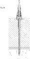
- FIG. 1 shows an embodiment of the assembly device 1 according to the invention.
- the assembly device 1 has a drive train 2, a transmission element 3, a stop disk 4 and a guide sleeve 5.
- the drive train 2 is designed to be connected to a drive unit, for example a cordless screwdriver (not shown).
- the transmission element 3 is designed to transmit a movement of the transmission element 3 to a fastening element (not shown here).
- the fastening element on the head can have a recess in the form of a cross slot and the transmission element 3 can have a corresponding projection.
- the transmission element 3 is connected to the drive train 2 in such a way that a movement of the drive train 2 leads to a corresponding movement of the transmission element 3.
- the drive train 2 and the transmission element 3 are designed in one piece.
- the person skilled in the art is also familiar with other possibilities for transferring the movement from the drive train 2 to the transmission element 3.
- the stop disk 4 is designed in order to limit the further forward movement of the assembly device 1 by resting on a surface of the subsurface.
- the surface on which the stop disk 4 rests at the end of assembly is made of a relatively soft material.
- the diameter of such a stop disk 4 is relatively large, in particular in comparison to the head of a fastening element.
- the assembly device 1 has a guide sleeve 5.
- This guide sleeve 5 guides the fastening element and in particular the head of the fastening element to the transmission element 3, so that both can be connected to one another in a simple manner.
- the guide sleeve 5 is designed at least partially funnel-shaped. As in Figure 1 As shown, the inner diameter of the guide sleeve 5 at the outer - here lower - edge is greater than in the area of the guide sleeve 5 in which the fastener head will be arranged during assembly.
- the guide sleeve 5 not only helps when arranging the assembly device 1 on the fastening element, but also assists in holding the fastening element during assembly.
- the embodiment shown of the assembly device 1 according to the invention has a resilient guide sleeve 5.
- the guide sleeve 5 can be seen in a first position into which it is pressed by a spring 6. In this first position, the guide sleeve 5 helps to arrange the assembly device 1 on the fastening element.
- the head of the fastening element ensures that the guide sleeve 5 is moved back slightly against the spring force so that the means of the transmission element 3 can engage in the countermeasure of the fastening element in the best possible way.
- This position of the guide sleeve 5 is in Figure 2a shown enlarged at the bottom right.
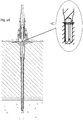
- the guide sleeve 5 touches the surface of the substrate or a plate of a dowel before the stop disk 4 rests on the surface. So that the guide sleeve 5 is not in the way during further assembly, a further forward movement of the assembly device 1 results in the guide sleeve 5 being moved further backwards against the spring force relative to the transmission element 3 and to the stop disk 4 until the guide sleeve 5 relative to the stop disk 4 no longer protrudes.
- This position of the guide sleeve 5 is in Figure 2c shown enlarged at the bottom right.
- the stop disk 4 is realized by a stop plate 4a and a stop shaft 4b.
- the stop plate 4a is designed to rest on the surface of the subsurface and thus to prevent further forward movement of the assembly device 1.
- This stop plate 4a is connected to the drive train 2 via the stop shaft 4b.
- the stop shaft 4b has at least partially an inner diameter that is larger than the outer diameter of the guide sleeve 5, so that the guide sleeve 5 can be moved at least partially into the stop shaft 4b.
- the spring 6 is supported on the stop shaft 4b. In principle, however, it is also possible for the spring 6 to be supported on the drive train 2.
- connection shaft 4b is in the in Figure 1
- the embodiment shown is also designed in such a way that it and thus also the stop plate 4a and the guide sleeve 5 can be moved relative to the drive train 2.
- the distance at the end of an assembly between the head of a fastening element and the surface of the substrate in which the fastening element is arranged can be adjusted.
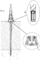
- Figure 2 illustrates the assembly according to the invention using the example of the assembly of an insulation holder in an insulation material in several steps.
- the dowel 20 with the fastening element 21 is already in the substrate 10 and the transmission element 3 of the assembly device 1 is arranged on the fastening element 21.
- the transmission element 3 has a means in the form of an external hexagon, that is to say an Allen key
- the fastening means 21 has a corresponding counter-means in the form of a recess 22 which forms a corresponding internal hexagon.
- the fastening element 21 has a head 23 with an outer surface 24.
- the guide sleeve 5 of the assembly device 1 is funnel-shaped at least on the inside and is designed in such a way that it guides the fastening element 21 on the outer surface 24 in such a way that the means of the transmission element 3, in the present example the Allen key, with the counter-means of the fastening element 21, in the present example, the recess 22 can be effectively connected.
- the transmission element 3 penetrates far into the recess 22 of the fastening element 21.
- the penetration depth is in the in Figure 2a
- the enlarged view shown at the top right is illustrated with the curly brackets.
- the fastening element 21 is a screw.
- the fastening element 21 is by a rotary movement of the
- a rotary movement of the drive train 2 of the assembly device 1 continues to cause a rotary movement of the fastening element 21 with the aid of the transmission element 3.
- This rotary movement moves the fastening element 21 further into the substrate 10. Since in this embodiment the head 23 of the fastening element 21 now rests against a stop of the plate of the dowel 20, the movement of the fastening element 21 into the substrate 10 also causes the plate of the dowel 20 to be moved into the substrate 10. If, however, the stop plate 4a of the assembly device 1 rests on the surface 11 of the substrate 10, the assembly tool 1 cannot move any further.
- the fastening element 21 moves away from the transmission element 3 and therefore in the present exemplary embodiment also the Allen key of the transmission element out of the hexagon socket of the fastening element 21 until there is no longer an effective connection.
- This position is in Figure 2d shown, the curly brackets in the enlarged view shown above on the right represents the now significantly reduced depth of penetration.
Landscapes
- Engineering & Computer Science (AREA)
- Mechanical Engineering (AREA)
- Architecture (AREA)
- Civil Engineering (AREA)
- Structural Engineering (AREA)
- Connection Of Plates (AREA)
- Auxiliary Devices For And Details Of Packaging Control (AREA)
- Telephone Function (AREA)
- Vehicle Body Suspensions (AREA)
Description
- Die vorliegende Erfindung betrifft eine Montagevorrichtung, insbesondere zur Montage eines Dämmstoffdübels sowie ein entsprechendes Verfahren.
- Zur Montage von Dübeln, insbesondere in einem Dämmstoff werden häufig Montagewerkzeuge mit einem Übertragungselement und einer Anschlagscheibe verwendet. Ein Beispiel für ein derartiges Montagewerkzeug ist in
EP 2 191 938 beschrieben. Montagewerkzeuge helfen dabei, den Dübel in einer vorbestimmten Position relativ zur Oberfläche, insbesondere des Dämmstoffs zu setzen. Mit dem Übertragungselement wird eine Bewegung des Montagewerkzeugs beispielsweise auf ein Spreizelement übertragen, mit dem ein Dübel in einem Untergrund befestigt wird. Die Anschlagscheibe ist derart ausgestaltet und an dem Montagewerkzeug angeordnet, dass sie während der Montage auf der Oberfläche des Untergrunds aufsetzt und somit verhindert, dass die Montagevorrichtung und somit beispielsweise auch das Spreizelement weiter in den Untergrund bewegt werden kann. - Damit die Anschlagscheibe auch bei weicheren Oberflächen, beispielsweise aus Dämmstoff ohne Verformung der Oberfläche angeordnet werden kann, haben die Anschlagscheiben meistens einem im Vergleich zum Kopf des Spreizelements sehr großen Durchmesser. Dies führt aber dazu, dass der Monteur bei der Anordnung des Montagewerkzeugs an dem Spreizelement den Spreizelementkopf häufig nicht sehen kann, was das Anordnen des Montagewerkzeugs an dem Spreizelementkopf wesentlich erschwert.
- Die Aufgabe der vorliegenden Erfindung ist es daher eine Montagevorrichtung bereitzustellen, mit der das Anordnen der Montagevorrichtung an einem Befestigungselement wesentlich vereinfacht werden kann.
- Diese Aufgabe wird durch die Montagevorrichtung nach Anspruch 1 sowie das Montageverfahren nach Anspruch 7 gelöst.
- Die erfindungsgemäße Montagevorrichtung kann für die Montage der unterschiedlichsten Befestigungsmittel verwendet werden. Im Folgenden wird ihre Funktion beispielhaft anhand der Montage eines Dämmstoffdübels beschrieben. Der Fachmann weiß aber, dass sich die Vorteile der Erfindung auch bei der Montage von anderen Befestigungsmitteln ergeben.
- Die erfindungsgemäße Montagevorrichtung weist einen Antriebsstrang, ein Übertragungselement und eine Anschlagscheibe auf. Der Antriebsstrang ist ein Element, das insbesondere mit einer Antriebseinrichtung, beispielsweise einem Akkuschrauber verbunden werden kann. Die Antriebseinrichtung treibt den Antriebsstrang an. Dies führt in vielen Fällen dazu, dass sich der Antriebsstrang dreht. Wenn der Antriebsstrang aber beispielsweise mit einem Bohrhammer verbunden wird, führt dies zu einer Vorwärtsbewegung des Antriebsstrangs.
- Damit die Bewegung des Antriebsstrangs auf das Befestigungselement übertragen werden kann, weist die erfindungsgemäße Montagevorrichtung ein Übertragungselement auf. Das Übertragungselement kann einstückig mit dem Antriebsstrang ausgebildet sein oder mit dem Antriebsstrang derart direkt oder indirekt verbunden sein, dass die Bewegung des Antriebsstrangs zumindest teilweise auf das Übertragungselement übertragen wird.
- Das Übertragungselement ist ausgestaltet, um seine Bewegung auf ein an dem Übertragungselement angeordnetes Befestigungselement, insbesondere eines Dämmstoffdübels zu übertragen. Hierfür kann das Übertragungselement beispielsweise an einem Ende mindestens ein Mittel aufweisen, das mit mindestens einem entsprechenden Gegenmittel an dem Befestigungselement zusammenwirken kann. Bei dem Mittel oder Gegenmittel kann es sich beispielsweise um einen oder mehrere Vorsprünge oder um eine oder mehrere Ausnehmungen handeln. Diese können beispielsweise als Schlitz, Kreuzschlitz, Sechskant oder Torx ausgestaltet sein. Dem Fachmann sind aber auch noch weitere Schraubenkopfantriebe bekannt, die im Rahmen der vorliegenden Erfindung realisiert werden können. Darüber hinaus kann das Übertragungselement auch ausgestaltet sein, um andere Bewegungen als Schraubbeziehungsweise Drehbewegungen - alternativ oder zusätzlich - auf das Befestigungselement zu übertragen. Im Rahmen der vorliegenden Erfindung kann das
- Übertragungselement auch durch einen Bithalter realisiert werden, in dem ein für das gerade verwendete Befestigungselement geeigneter Bit angeordnet werden kann.
- Im Rahmen der vorliegenden Erfindung umfasst der Kopf eines Befestigungselements der Bereich des Befestigungselements, der mit dem Übertragungsmittel zusammenwirkt. Erfahrungsgemäß hat der Kopf eines Befestigungselements einen größeren Querschnitt als der restliche Bereich des Befestigungselements. Im Rahmen der vorliegenden Erfindung muss das nicht notwendigerweise der Fall sein. Gemäß einer bevorzugten Ausführungsform der Erfindung hat der Kopf aber eine größere Querschnittsfläche als der restliche Bereich des Befestigungselements. Der Kopf hat eine obere Oberfläche, die zu dem Übertragungselement zeigt. Wenn das Mittel und das Gegenmittel beispielsweise als Schlitz oder Kreuzschlitz ausgestaltet sind, befindet sich in der oberen Oberfläche eine Ausnehmung. Darüber hinaus hat der Kopf eine äußere Oberfläche. Dies ist die Fläche, die bei einer Außensechskantverbindung (im Gegensatz zu einem Befestigungselement mit einem Innensechskant, wie einem Inbus) als Sechskant ausgestaltet ist. Diese äußere Oberfläche kann auch als Umfangsfläche des Kopfs des Befestigungselements bezeichnet werden.
- Die Anschlagscheibe ist vorzugsweise in einer bestimmten Position relativ zu dem Ende des Übertragungselements angeordnet, an dem das Befestigungselement angeordnet wird. Diese Position entspricht vorzugsweise dem gewünschten Abstand zwischen dem Befestigungselement, insbesondere der oberen Oberfläche des Kopfs des Befestigungselements, und der Oberfläche des Untergrunds, beispielsweise des Dämmstoffs nach der Montage. Die Anschlagscheibe kann hierfür direkt oder indirekt beispielsweise an dem Antriebsstrang oder dem Übertragungselement angeordnet sein. In einer bevorzugten Ausführungsform ist die Anschlagscheibe verstellbar angeordnet, das heißt sie kann an unterschiedlichen Positionen angeordnet werden, damit der gewünschte Abstand eingestellt werden kann. Alternativ oder zusätzlich kann die Anschlagscheibe auch lösbar angeordnet sein.
- Erfindungsgemäß weist die Montagevorrichtung eine Führungshülse auf. In der Führungshülse wird das Befestigungselement, insbesondere der Kopf des Befestigungselements aufgenommen. Die erfindungsgemäße Führungshülse hilft dem Monteur das Befestigungselement zu dem Übertragungselement zu führen oder umgekehrt. Damit kann die Montage von Befestigungselementen wesentlich vereinfacht und auch beschleunigt werden.
- Im Rahmen der vorliegenden Erfindung ist eine Hülse ein Element, das derart ausgestaltet und angeordnet ist, dass es den Kopf des Befestigungselements zu der Position führt, in der er von dem Übertragungselement dann gehalten wird. Diese Hülse muss dafür nicht notwendigerweise eine geschlossene Mantelfläche aufweisen. Im Rahmen der vorliegenden Erfindung kann die Führungshülse auch durch mehrere Elemente, vorzugsweise mindestens drei Elemente, gebildet werden, die das Befestigungselement und insbesondere den Kopf des Befestigungselements führen. Die Führungshülse berührt und führt das Befestigungselement und insbesondere den Kopf des Befestigungselements vorzugsweise von außen, das heißt im Zusammenspiel mit der äußeren Oberfläche des Kopfs des Befestigungselements. Die Führungshülse ist derart ausgestaltet, dass sie um das Übertragungselement herum angeordnet ist.
- Erfindungsgemäß umfasst der Kopf des Befestigungselements den Bereich der mit dem Übertragungselement zusammenwirkt und den Bereich, der von der Führungshülse geführt wird.
- Darüber hinaus eilt die Führungshülse in einer bevorzugten Ausführungsform dem Übertragungselement voraus, so dass ein Befestigungselement beziehungsweise der Kopf eines Befestigungselements zuerst in einen Bereich der Hülse geführt wird, in dem sich das Übertragungselement nicht befindet, bevor es an dem Übertragungselement angeordnet wird.
- Erfindungsgemäß ist die Führungshülse beweglich und federnd an der restlichen Montagevorrichtung angeordnet. Die Führungshülse kann beispielsweise an dem Übertragungselement, dem Antriebsstrang oder der Anschlagscheibe direkt oder indirekt federnd angeordnet sein. Durch die federnde Anordnung wird die Hülse in einer Position gehalten, kann aber gegen die Federkraft von dieser Position weg bewegt werden. Die Hülse ist vorzugsweise relativ zu dem Übertragungselement und/oder der Anschlagscheibe beweglich angeordnet.
- Vorzugsweise ist die Führungshülse derart angeordnet, dass ein vorderes Ende der Führungshülse in einer ersten Position gegenüber der Anschlagscheibe hervorsteht und in einer zweiten Position mit der Anschlagscheibe im Wesentlichen planar ausgerichtet ist. Erfindungsgemäß wird die Montagevorrichtung dann derart verwendet, dass vor der Montage die Führungshülse von der Anschlagscheibe hervorsteht und somit das Anordnen des Befestigungselements an dem Übertragungselement der Montagevorrichtung erleichtert. Im Rahmen der Montage wird die Montagevorrichtung in Richtung der Oberfläche des Untergrunds bewegt. Zuerst trifft die hervorstehende Führungshülse auf den Untergrund und wird dadurch relativ zu der restlichen Montagevorrichtung nach hinten bewegt, bis die Führungshülse gegenüber der Anschlagscheibe nicht mehr hervorsteht.
- Die Anschlagscheibe verhindert, dass sich das Montagewerkzeug weiter in Richtung Untergrund bewegt, sobald die Anschlagscheibe auf dem Untergrund aufliegt. Dies hat aber keinen Einfluss auf die durch den Antriebsstrang verursachte Bewegung des Übertragungselements. Die Bewegung des Übertragungselements wird so lange auf das Befestigungselement übertragen, wie eine wirksame Verbindung zwischen dem Übertragungselement und dem Befestigungselement besteht. Wenn beispielsweise eine Torx- oder Inbusverbindung zwischen Übertragungselement und Befestigungselement besteht und der Antriebsstrang beispielsweise eine Drehbewegung ausführt, wird diese Drehbewegung so lange auf das Befestigungselement übertragen, so lange in diesem Beispiel der Torx oder der Inbus ausreichend weit in die entsprechende Öffnung in dem Befestigungselement hineinreicht. Wenn also die Anschlagscheibe auf dem Untergrund aufliegt, sorgt das Übertragungselement weiterhin dafür, dass das Befestigungselement bewegt wird. Wenn beispielsweise das Befestigungselement eine Schraube ist und die Bewegung eine Drehbewegung, verursacht das Übertragungselement, dass sich das Befestigungselement weiterdreht und sich somit weiter in den Untergrund bewegt. Da sich die Montagevorrichtung aber nicht mehr näher zum Untergrund bewegen kann, führt dies zu einer Relativbewegung zwischen Montagevorrichtung und Befestigungselement, insbesondere zu einer Relativbewegung zwischen dem oben erläuterten Mittel des Übertragungselements und dem Gegenmittel an dem Befestigungselement. Durch diese Relativbewegung verringert sich die Fläche an der Mittel und Gegenmittel zusammenwirken, bis keine wirksame Verbindung mehr besteht und somit die Bewegung des Übertragungselements nicht mehr auf das Befestigungselement übertragen wird.
- Wie oben bereits erläutert, ist die Position der Anschlagscheibe an der Montagevorrichtung einstellbar. Dadurch ist auch einstellbar, in welchem Abstand von der Oberfläche des Untergrunds die Wirksamkeit der Verbindung zwischen Mittel und Gegenmittel aufhört. Somit kann eingestellt werden, an welcher Position des Befestigungselements relativ zur Oberfläche des Untergrunds der Montagevorgang enden soll. Diese Position kann in Abhängigkeit von der Beschaffenheit des Untergrunds gewählt werden. Aber auch das verwendete Mittel und Gegenmittel spielt dabei eine Rolle.
- In einer bevorzugten Ausführungsform ist die Führungshülse zumindest teilweise trichterförmig ausgestaltet ist. So kann die Hülse oder können die Elemente, die die Hülse bilden, in dem Bereich in dem das Befestigungselement an dem Übertragungselement gehalten wird, einen kleineren Umfang bilden, als in einem davon beabstandeten Bereich. Wenn das Befestigungselement an dem Übertragungselement angeordnet werden soll, kann es zuerst mit Hilfe des Hülsenbereichs mit größerem Durchmesser in die Hülse geführt werden und dann in der Hülse zu dem Übertragungselement geführt werden. Durch die trichterförmige Ausgestaltung der Führungshülse wird es noch einfacher das Befestigungselement schnell an dem Übertragungselement anzuordnen.
- Gemäß einer weiteren bevorzugten Ausführungsform weist die Anschlagscheibe einen tellerförmigen Bereich und einen Schaft auf. Im Folgenden wird der tellerförmige Bereich als Anschlagteller und der Schaft als Anschlagschaft bezeichnet. In dieser Ausführungsform kann der Anschlagteller mit Hilfe des Anschlagschafts an dem Antriebsstrang befestigt werden. Der Anschlagschaft kann derart ausgestaltet sein, dass die Führungshülse zumindest teilweise in ihn hinein bewegt werden kann. Darüber hinaus kann sich die Feder einer federnden Führungshülse zumindest teilweise an dem Anschlagschaft abstützen. Der Anschlagteller muss nicht notwendigerweise eine durchgehende Tellerfläche aufweisen. Im Stand der Technik sind bereits unterschiedliche Ausgestaltungen für die Teller von Anschlagscheiben bekannt. Die Teller können beispielsweise Öffnungen aufweisen oder als ein umlaufender Ring mit Speichen ausgestaltet sein.
- Das erfindungsgemäße Verfahren dient der Montage eines Dübels in einem Untergrund, wobei das Verfahren im Folgenden anhand der Montage eines Dämmstoffdübels in einem Dämmstoff erläutert wird. Für die Montage wird eine Montagevorrichtung verwendet. Im Rahmen der Montage wird ein Befestigungselement des Dübels an einem Übertragungselement der Montagevorrichtung angeordnet. Dabei führt eine Führungshülse der Montagevorrichtung das Befestigungselement zu dem Übertragungselement. Der Fachmann versteht, dass es hierbei lediglich darum geht die beiden Elemente zueinander hin zu bewegen. Dabei ist es möglich, dass nur ein Element bewegt wird, also das Befestigungselement oder das Übertragungselement. Es ist aber auch möglich, dass beide Elemente zueinander bewegt werden. Im Rahmen des erfindungsgemäßen Verfahrens wird von einem Antriebsstrang der Montagevorrichtung eine Bewegung auf das Übertragungselement übertragen und dadurch auch auf ein daran angeordnetes Befestigungselement, um den Dübel zu montieren. Diese Bewegung wird zumindest so lange übertragen, bis die Anschlagscheibe der Montagevorrichtung auf dem Untergrund liegt. Wie oben erläutert, wird die Bewegung auch nach dem Aufliegen der Anschlagscheibe am Untergrund so lange weiter übertragen, wie die Verbindung zwischen Übertragungselement und Befestigungselement wirksam ist.
- Die Erfindung wird nachfolgend anhand eines in den beigefügten Zeichnungen dargestellten Ausführungsbeispiels näher erläutert. Aus dem beschriebenen Ausführungsbeispiel ergeben sich weitere Einzelheiten, Merkmale und Vorteile des Gegenstands der Erfindung. Es zeigen:
- Fig. 1
- eine Schnittansicht einer Ausführungsform der erfindungsgemäßen Montagevorrichtung; und
- Fig. 2
- die Montage mit Hilfe der erfindungsgemäßen Montagevorrichtung in mehreren Schritten.
-
Figur 1 zeigt eine Ausführungsform der erfindungsgemäßen Montagevorrichtung 1. Die Montagevorrichtung 1 weist einen Antriebsstrang 2, ein Übertragungselement 3, eine Anschlagscheibe 4 und eine Führungshülse 5 auf. Der Antriebsstrang 2 ist ausgestaltet, um mit einer Antriebseinheit, beispielsweise einem Akkuschrauber (nicht gezeigt) verbunden zu werden. Das Übertragungselement 3 ist ausgestaltet, um eine Bewegung des Übertragungselements 3 auf ein Befestigungselement (hier nicht gezeigt) zu übertragen. Beispielsweise kann das Befestigungselement am Kopf eine Ausnehmung in Form eines Kreuzschlitzes und das Übertragungselement 3 einen entsprechenden Vorsprung aufweisen. Das Übertragungselement 3 ist derart mit dem Antriebsstrang 2 verbunden, dass eine Bewegung des Antriebsstrangs 2 zu einer entsprechenden Bewegung des Übertragungselements 3 führt. In der inFigur 1 gezeigten Ausführungsform ist dies dadurch realisiert, dass der Antriebsstrang 2 und das Übertragungselement 3 einstückig ausgestaltet sind. Dem Fachmann sind aber auch andere Möglichkeiten bekannt, um die Bewegung von dem Antriebsstrang 2 auf das Übertragungselement 3 zu übertragen. - Die Anschlagscheibe 4 ist ausgestaltet, um durch das Aufliegen auf einer Oberfläche des Untergrunds die weitere Vorwärtsbewegung der Montagevorrichtung 1 zu begrenzen. Insbesondere wenn die Montagevorrichtung 1 zur Montage von Dämmstoffdübeln verwendet wird, besteht die Oberfläche, an der die Anschlagscheibe 4 am Ende der Montage aufliegt, aus einem relativ weichen Material. Um Abdrücke in dem Material und Beschädigungen zu vermeiden, ist der Durchmesser einer derartigen Anschlagscheibe 4 relativ groß, insbesondere im Vergleich zu dem Kopf eines Befestigungselements. Dies führt aber dazu, dass ein Monteur, der mit der Montagevorrichtung 1 beispielsweise ein bereits teilweise in einen Untergrund eingebrachtes Befestigungselement montieren will, aufgrund der Anschlagscheibe 4 das Übertragungselement 3 und den Kopf des Befestigungselements nicht sehen kann, wenn er beide miteinander verbinden will.
- Um dies zu vereinfachen, weist die erfindungsgemäße Montagevorrichtung 1 eine Führungshülse 5 auf. Diese Führungshülse 5 führt das Befestigungselement und insbesondere den Kopf des Befestigungselements zu dem Übertragungselement 3, so dass beide auf einfache Weise miteinander verbunden werden können. Um das Ausrichten der Montagevorrichtung 1 gegenüber dem Befestigungselement zu vereinfachen, ist die Führungshülse 5 zumindest teilweise trichterförmig ausgestaltet. Wie in
Figur 1 gezeigt, ist der Innendurchmesser der Führungshülse 5 am äußeren - hier unteren - Rand größer als in dem Bereich der Führungshülse 5, in dem der Befestigungselementkopf während der Montage angeordnet sein wird. Die Führungshülse 5 hilft aber nicht nur bei dem Anordnen der Montagevorrichtung 1 an dem Befestigungselement, sondern unterstützt auch das Halten des Befestigungselements während der Montage. - Die in
Figur 1 gezeigte Ausführungsform der erfindungsgemäßen Montagevorrichtung 1 weist eine federnde Führungshülse 5 auf. InFigur 1 ist die Führungshülse 5 in einer ersten Position zu sehen, in die sie von einer Feder 6 gedrückt wird. In dieser ersten Position hilft die Führungshülse 5 bei dem Anordnen der Montagevorrichtung 1 an dem Befestigungselement. Wenn das Befestigungselement an dem Übertragungselement 3 angeordnet wird, sorgt bei der hier gezeigten Ausführungsform der Kopf des Befestigungselements dafür, dass die Führungshülse 5 gegen die Federkraft etwas zurückbewegt wird, damit das Mittel des Übertragungselements 3 bestmöglich in das Gegenmittel des Befestigungselements eingreifen kann. Diese Position der Führungshülse 5 ist inFigur 2a rechts unten vergrößert gezeigt. Wenn während der Montage die Montagevorrichtung 1 weiter in Richtung Untergrund bewegt wird, berührt die Führungshülse 5 die Oberfläche des Untergrunds oder einen Teller eines Dübels bevor die Anschlagscheibe 4 auf der Oberfläche aufliegt. Damit die Führungshülse 5 dann bei der weiteren Montage nicht im Weg ist, führt ein weiteres Vorwärtsbewegen der Montagevorrichtung 1 dazu, dass die Führungshülse 5 relativ zu dem Übertragungselement 3 und zu der Anschlagscheibe 4 gegen die Federkraft weiter nach hinten bewegt wird, bis die Führungshülse 5 gegenüber der Anschlagscheibe 4 nicht mehr hervorsteht. Diese Position der Führungshülse 5 ist inFigur 2c rechts unten vergrößert gezeigt. - Bei der in
Figur 1 gezeigten Ausführungsform wird die Anschlagscheibe 4 durch einen Anschlagteller 4a und einen Anschlagschaft 4b realisiert. Der Anschlagteller 4a ist ausgestaltet, um auf der Oberfläche des Untergrunds aufzuliegen und somit eine weitere Vorwärtsbewegung der Montagevorrichtung 1 zu verhindern. Dieser Anschlagteller 4a ist über den Anschlagschaft 4b mit dem Antriebsstrang 2 verbunden. Dabei hat der Anschlagschaft 4b zumindest teilweise einen Innendurchmesser, der größer ist als der Außendurchmesser der Führungshülse 5, so dass die Führungshülse 5 zumindest teilweise in den Anschlagschaft 4b bewegt werden kann. In dieser Ausführungsform stützt sich die Feder 6 an dem Anschlagschaft 4b ab. Es ist aber auch grundsätzlich möglich, dass sich die Feder 6 an dem Antriebsstrang 2 abstützt. - Der Anschalgschaft 4b ist in der in
Figur 1 gezeigten Ausführungsform auch derart ausgestaltet, dass er und somit auch der Anschlagteller 4a und die Führungshülse 5 relativ zu dem Antriebsstrang 2 bewegt werden können. Somit kann der Abstand am Ende einer Montage zwischen dem Kopf eines Befestigungselements und der Oberfläche des Untergrunds, in dem das Befestigungselement angeordnet wird, eingestellt werden. -
Figur 2 veranschaulicht die erfindungsgemäße Montage am Beispiel der Montage eines Dämmstoffhalters in einem Dämmstoff in mehreren Schritten. - In der ersten Ansicht (
Figur 2a ) befindet sich der Dübel 20 mit dem Befestigungselement 21 bereits in dem Untergrund 10 und das Übertragungselement 3 der Montagevorrichtung 1 ist an dem Befestigungselement 21 angeordnet. In dem hier gezeigten Ausführungsbeispiel weist das Übertragungselement 3 ein Mittel in Form eines Außensechskants, das heißt eines Inbus auf und das Befestigungsmittel 21 ein entsprechendes Gegenmittel in Form einer Ausnehmung 22, die einen entsprechenden Innensechskant bildet. Das Befestigungselement 21 weist einen Kopf 23 mit einer äußeren Oberfläche 24 auf. Die Führungshülse 5 der Montagevorrichtung 1 ist zumindest innen trichterförmig und ist derart ausgestaltet, dass sie das Befestigungselement 21 an der äußeren Oberfläche 24 derart führt, dass das Mittel des Übertragungselements 3, in dem vorliegenden Beispiel der Inbus, mit dem Gegenmittel des Befestigungselements 21, in dem vorliegenden Beispiel die Ausnehmung 22, wirksam verbunden werden kann. Dabei dringt das Übertragungselement 3 weit in die Ausnehmung 22 des Befestigungselements 21 ein. Die Eindringtiefe ist in der inFigur 2a oben rechts dargestellten vergrößerten Ansicht mit der geschweiften Klammer veranschaulicht. - In dem hier gezeigten Ausführungsbeispiel ist das Befestigungselement 21 eine Schraube. Das Befestigungselement 21 wird durch eine Drehbewegung des
- Antriebsstrangs 2 und somit auch des Übertragungselements 3 gedreht und bewegt sich in dem Dübel 20 weiter in den Untergrund 10 bis der Anschlagteller 4a auf dem Teller des Dübels 20 aufliegt. Diese Position ist in der
Figur 2b veranschaulicht. In der vorliegenden Ausführungsform befindet sich der Inbus des Übertragungselements 3 in dieser Montageposition noch vollständig in dem Innensechskant des Befestigungselements 21. - Durch das Weiterdrehen des Antriebsstrangs 2 wird das Befestigungselement 21 weiter in den Untergrund 10 bewegt. Da sich die Montagevorrichtung 1 aber nicht weiter in Richtung Untergrund 10 bewegt, führt dies zu einer Relativbewegung zwischen Übertragungselement 3 und Befestigungselement 21. Dementsprechend bewegt sich der Inbus des Übertragungselements 3 aus dem Innensechskant des Befestigungselement 21 heraus. Dies ist in
Figur 2c veranschaulicht, wobei in der inFigur 2c oben rechts dargestellten Ansicht mit der geschweiften Klammer die nun verringerte Eindringtiefe dargestellt ist. Der Inbus ist aber noch immer soweit in dem Innensechskant, dass beide wirksam miteinander verbunden sind. - Dadurch bewirkt eine Drehbewegung des Antriebsstrangs 2 der Montagevorrichtung 1 weiterhin mit Hilfe des Übertragungselements 3 eine Drehbewegung des Befestigungselements 21. Durch diese Drehbewegung wird das Befestigungselement 21 weiter in den Untergrund 10 bewegt. Da in dieser Ausführungsform der Kopf 23 des Befestigungselements 21 nun an einem Anschlag des Tellers des Dübels 20 anliegt, bewirkt die Bewegung des Befestigungselements 21 in den Untergrund 10 auch dass der Teller des Dübels 20 in den Untergrund 10 bewegt wird. Wenn der Anschlagteller 4a der Montagevorrichtung 1 aber auf der Oberfläche 11 des Untergrunds 10 aufliegt, kann sich das Montagewerkzeug 1 nicht weiter bewegen. Somit bewegt sich das Befestigungselement 21 von dem Übertragungselement 3 weg und deshalb in dem vorliegenden Ausführungsbeispiel auch der Inbus des Übertragungselements aus dem Innensechskant des Befestigungselements 21 soweit heraus, bis keine wirksame Verbindung mehr besteht. Diese Position ist in
Figur 2d gezeigt, wobei die geschweifte Klammer bei der oben rechts dargestellten vergrößerten Ansicht die nun deutlich verringerte Eindringtiefe darstellt.
Claims (7)
- Eine Montagevorrichtung (1), insbesondere zur Montage von Dämmstoffdübeln, aufweisend:einen Antriebsstrang (2),ein Übertragungselement (3) zur Übertragung einer Bewegung von dem Antriebsstrang (2) auf ein Befestigungselement undeine Anschlagscheibe (4),
dadurch gekennzeichnet, dassdie Montagevorrichtung (1) eine Führungshülse (5) aufweist, zur Führung des Befestigungselements bei dem Anordnen des Befestigungselements an dem Übertragungselement (3), wobei die Führungshülse (5) federnd an der restlichen Montagevorrichtung (1) angeordnet ist. - Die Montagevorrichtung (1) gemäß Anspruch 1, wobei ein vorderes Ende der Führungshülse (5) in einer ersten Position gegenüber der Anschlagscheibe (4) hervorsteht und in einer zweiten Position mit der Anschlagscheibe (4) ausgerichtet ist.
- Die Montagevorrichtung (1) gemäß einem der vorhergehenden Ansprüche, wobei die Führungshülse (5) zumindest teilweise trichterförmig ausgestaltet ist.
- Die Montagevorrichtung (1) gemäß einem der vorhergehenden Ansprüche, wobei die Anschlagscheibe (4) verschiebbar an dem Antriebsstrang (2) angeordnet ist.
- Die Montagevorrichtung (1) gemäß einem der vorhergehenden Ansprüche, wobei an der Anschlagscheibe (4) einen Anschlagteller (4a) und einen Anschlagschaft (4b) aufweist und wobei der Anschlagteller (4a) mit dem Anschlagschaft (4b) an dem Antriebsstrang (2) befestigt ist.
- Die Montagevorrichtung (1) gemäß Anspruch 5, wobei die Führungshülse (5) derart angeordnet ist, dass sie in den Anschlagschaft (4b) bewegt werden kann.
- Ein Verfahren zur Montage eines Dübels in einem Untergrund, insbesondere eines Dämmstoffdübels in einem Dämmstoff mit Hilfe einer Montagevorrichtung (1), wobei das Verfahren die folgenden Schritte aufweist:Anordnen eines Befestigungselements des Dübels an einem Übertragungselement (3) der Montagevorrichtung, wobei eine Führungshülse (5), die federnd an der restlichen Montagevorrichtung (1) angeordnet ist, das Befestigungselement zu dem Übertragungselement (3) führt,Übertragen einer Bewegung von einem Antriebsstrang (2) der Montagevorrichtung (1) auf das Übertragungselement (3) und dadurch auch auf das Befestigungselement zum Montieren des Dübels bis eine Anschlagscheibe (4) der Montagevorrichtung (1) auf dem Untergrund aufliegt.
Priority Applications (8)
| Application Number | Priority Date | Filing Date | Title |
|---|---|---|---|
| PL18160413T PL3536459T3 (pl) | 2018-03-07 | 2018-03-07 | Urządzenie montażowe |
| RS20210568A RS61813B1 (sr) | 2018-03-07 | 2018-03-07 | Uređaj za montiranje |
| LTEP18160413.3T LT3536459T (lt) | 2018-03-07 | 2018-03-07 | Montavimo aparatas |
| HUE18160413A HUE055257T2 (hu) | 2018-03-07 | 2018-03-07 | Szerelõszerkezet |
| ES18160413T ES2884065T3 (es) | 2018-03-07 | 2018-03-07 | Dispositivo de montaje |
| SI201830354T SI3536459T1 (sl) | 2018-03-07 | 2018-03-07 | Montažna naprava |
| EP18160413.3A EP3536459B1 (de) | 2018-03-07 | 2018-03-07 | Montagevorrichtung |
| HRP20211183TT HRP20211183T1 (hr) | 2018-03-07 | 2021-07-22 | Naprava za ugradnju |
Applications Claiming Priority (1)
| Application Number | Priority Date | Filing Date | Title |
|---|---|---|---|
| EP18160413.3A EP3536459B1 (de) | 2018-03-07 | 2018-03-07 | Montagevorrichtung |
Publications (2)
| Publication Number | Publication Date |
|---|---|
| EP3536459A1 EP3536459A1 (de) | 2019-09-11 |
| EP3536459B1 true EP3536459B1 (de) | 2021-05-05 |
Family
ID=61581095
Family Applications (1)
| Application Number | Title | Priority Date | Filing Date |
|---|---|---|---|
| EP18160413.3A Active EP3536459B1 (de) | 2018-03-07 | 2018-03-07 | Montagevorrichtung |
Country Status (8)
| Country | Link |
|---|---|
| EP (1) | EP3536459B1 (de) |
| ES (1) | ES2884065T3 (de) |
| HR (1) | HRP20211183T1 (de) |
| HU (1) | HUE055257T2 (de) |
| LT (1) | LT3536459T (de) |
| PL (1) | PL3536459T3 (de) |
| RS (1) | RS61813B1 (de) |
| SI (1) | SI3536459T1 (de) |
Families Citing this family (4)
| Publication number | Priority date | Publication date | Assignee | Title |
|---|---|---|---|---|
| EP3970915B1 (de) | 2020-09-22 | 2023-02-15 | RANIT-Befestigungssysteme GmbH | Montagewerkzeug und verfahren zur montage einer dämmstoffplatte |
| PL3978194T3 (pl) | 2020-10-01 | 2024-10-28 | Ranit-Befestigungssysteme Gmbh | Narzędzie montażowe do montażu płyty izolacyjnej |
| DE102022214257A1 (de) * | 2022-12-21 | 2024-06-27 | Ejot Se & Co. Kg | Montagevorrichtung mit Entkopplungsmechanismus |
| DE102022214254A1 (de) * | 2022-12-21 | 2024-06-27 | Ejot Se & Co. Kg | Montagevorrichtung mit lösbarer Kupplung |
Family Cites Families (2)
| Publication number | Priority date | Publication date | Assignee | Title |
|---|---|---|---|---|
| DE102007000235A1 (de) * | 2007-04-20 | 2008-10-23 | Hilti Aktiengesellschaft | Setzwerkzeug für einen Dämmstoffdübel |
| DE102008044124A1 (de) * | 2008-11-27 | 2010-06-02 | Hilti Aktiengesellschaft | Setzwerkzeug für einen Dämmstoffdübel |
-
2018
- 2018-03-07 HU HUE18160413A patent/HUE055257T2/hu unknown
- 2018-03-07 LT LTEP18160413.3T patent/LT3536459T/lt unknown
- 2018-03-07 RS RS20210568A patent/RS61813B1/sr unknown
- 2018-03-07 SI SI201830354T patent/SI3536459T1/sl unknown
- 2018-03-07 EP EP18160413.3A patent/EP3536459B1/de active Active
- 2018-03-07 PL PL18160413T patent/PL3536459T3/pl unknown
- 2018-03-07 ES ES18160413T patent/ES2884065T3/es active Active
-
2021
- 2021-07-22 HR HRP20211183TT patent/HRP20211183T1/hr unknown
Also Published As
| Publication number | Publication date |
|---|---|
| EP3536459A1 (de) | 2019-09-11 |
| RS61813B1 (sr) | 2021-06-30 |
| PL3536459T3 (pl) | 2021-11-08 |
| SI3536459T1 (sl) | 2021-09-30 |
| HRP20211183T1 (hr) | 2021-10-15 |
| LT3536459T (lt) | 2021-05-25 |
| ES2884065T3 (es) | 2021-12-10 |
| HUE055257T2 (hu) | 2021-11-29 |
Similar Documents
| Publication | Publication Date | Title |
|---|---|---|
| EP1961976A2 (de) | Befestigungseinheit | |
| EP3536459A1 (de) | Montagevorrichtung | |
| DE10253888B4 (de) | Befestigungseinheit | |
| EP2623828A1 (de) | Sanitärventil | |
| EP3122981A2 (de) | Dichtungsvorrichtung und befestigungsmittel | |
| DE102019110297B3 (de) | Antriebsstrang mit Sicherheitskupplung | |
| WO2018171895A1 (de) | Fixierscheibe und verfahren zur anfänglichen fixierung eines befestigungselements und entfernen einer schutzfolie | |
| DE202009003184U1 (de) | Dichtungsvorrichtung zum Abdichten eines Durchbruchs | |
| DE102008006384A1 (de) | Pneumatikzylinder | |
| EP2041852B1 (de) | Schalter mit einer kupplung zur befestigung einer betätigungsvorrichtung | |
| EP3240962B1 (de) | Scheibenbremse, insbesondere für nutzfahrzeuge | |
| DE3311036C2 (de) | ||
| DE4304873A1 (de) | Schließvorrichtung | |
| EP3394495B1 (de) | Zahnscheibe mit mehrstegigen haltezähnen | |
| WO2017059836A1 (de) | Kraftfahrzeugtürschloss mit bewegungsdämpfer | |
| DE69705699T2 (de) | Ventil | |
| EP2740851B1 (de) | Spreizelement mit Abdeckscheibe | |
| DE2162090A1 (de) | Ausriickbare Mitnehmervorrichtung | |
| EP0973688B1 (de) | Zapfhahn | |
| DE3338217C2 (de) | Konterwerkzeug für Schraubverbindungen mit unterschiedlich großen Mehrkant-Mitnahmekörpern | |
| DE102012106745B4 (de) | Werkzeug für die Montage eines Dämmstoffdübels | |
| DE102015205623B4 (de) | Manuelles Schraubwerkzeug | |
| DE102017128474B3 (de) | Rohrschneidemaschine mit Schneiddorn | |
| DE2707124A1 (de) | Mechanische scheibenbremse | |
| DE102015212532A1 (de) | Montagewerkzeug, Montageverfahren sowie Verwendung eines flexiblen Bandes |
Legal Events
| Date | Code | Title | Description |
|---|---|---|---|
| PUAI | Public reference made under article 153(3) epc to a published international application that has entered the european phase |
Free format text: ORIGINAL CODE: 0009012 |
|
| STAA | Information on the status of an ep patent application or granted ep patent |
Free format text: STATUS: THE APPLICATION HAS BEEN PUBLISHED |
|
| AK | Designated contracting states |
Kind code of ref document: A1 Designated state(s): AL AT BE BG CH CY CZ DE DK EE ES FI FR GB GR HR HU IE IS IT LI LT LU LV MC MK MT NL NO PL PT RO RS SE SI SK SM TR |
|
| AX | Request for extension of the european patent |
Extension state: BA ME |
|
| STAA | Information on the status of an ep patent application or granted ep patent |
Free format text: STATUS: REQUEST FOR EXAMINATION WAS MADE |
|
| 17P | Request for examination filed |
Effective date: 20200129 |
|
| RBV | Designated contracting states (corrected) |
Designated state(s): AL AT BE BG CH CY CZ DE DK EE ES FI FR GB GR HR HU IE IS IT LI LT LU LV MC MK MT NL NO PL PT RO RS SE SI SK SM TR |
|
| GRAP | Despatch of communication of intention to grant a patent |
Free format text: ORIGINAL CODE: EPIDOSNIGR1 |
|
| STAA | Information on the status of an ep patent application or granted ep patent |
Free format text: STATUS: GRANT OF PATENT IS INTENDED |
|
| RIC1 | Information provided on ipc code assigned before grant |
Ipc: B25B 31/00 20060101AFI20201105BHEP Ipc: B25B 21/00 20060101ALI20201105BHEP Ipc: E04D 15/04 20060101ALI20201105BHEP |
|
| INTG | Intention to grant announced |
Effective date: 20201119 |
|
| GRAS | Grant fee paid |
Free format text: ORIGINAL CODE: EPIDOSNIGR3 |
|
| GRAA | (expected) grant |
Free format text: ORIGINAL CODE: 0009210 |
|
| STAA | Information on the status of an ep patent application or granted ep patent |
Free format text: STATUS: THE PATENT HAS BEEN GRANTED |
|
| AK | Designated contracting states |
Kind code of ref document: B1 Designated state(s): AL AT BE BG CH CY CZ DE DK EE ES FI FR GB GR HR HU IE IS IT LI LT LU LV MC MK MT NL NO PL PT RO RS SE SI SK SM TR |
|
| REG | Reference to a national code |
Ref country code: GB Ref legal event code: FG4D Free format text: NOT ENGLISH |
|
| REG | Reference to a national code |
Ref country code: CH Ref legal event code: EP Ref country code: CH Ref legal event code: NV Representative=s name: HEPP WENGER RYFFEL AG, CH |
|
| REG | Reference to a national code |
Ref country code: AT Ref legal event code: REF Ref document number: 1389211 Country of ref document: AT Kind code of ref document: T Effective date: 20210515 |
|
| REG | Reference to a national code |
Ref country code: DE Ref legal event code: R096 Ref document number: 502018005071 Country of ref document: DE |
|
| REG | Reference to a national code |
Ref country code: IE Ref legal event code: FG4D Free format text: LANGUAGE OF EP DOCUMENT: GERMAN |
|
| REG | Reference to a national code |
Ref country code: SE Ref legal event code: TRGR |
|
| REG | Reference to a national code |
Ref country code: EE Ref legal event code: FG4A Ref document number: E020831 Country of ref document: EE Effective date: 20210519 |
|
| REG | Reference to a national code |
Ref country code: NL Ref legal event code: FP |
|
| REG | Reference to a national code |
Ref country code: HR Ref legal event code: TUEP Ref document number: P20211183T Country of ref document: HR |
|
| REG | Reference to a national code |
Ref country code: SK Ref legal event code: T3 Ref document number: E 37298 Country of ref document: SK |
|
| REG | Reference to a national code |
Ref country code: FI Ref legal event code: FGE |
|
| REG | Reference to a national code |
Ref country code: RO Ref legal event code: EPE |
|
| REG | Reference to a national code |
Ref country code: HR Ref legal event code: T1PR Ref document number: P20211183 Country of ref document: HR |
|
| REG | Reference to a national code |
Ref country code: HU Ref legal event code: AG4A Ref document number: E055257 Country of ref document: HU |
|
| PG25 | Lapsed in a contracting state [announced via postgrant information from national office to epo] |
Ref country code: GR Free format text: LAPSE BECAUSE OF FAILURE TO SUBMIT A TRANSLATION OF THE DESCRIPTION OR TO PAY THE FEE WITHIN THE PRESCRIBED TIME-LIMIT Effective date: 20210806 Ref country code: IS Free format text: LAPSE BECAUSE OF FAILURE TO SUBMIT A TRANSLATION OF THE DESCRIPTION OR TO PAY THE FEE WITHIN THE PRESCRIBED TIME-LIMIT Effective date: 20210905 Ref country code: PT Free format text: LAPSE BECAUSE OF FAILURE TO SUBMIT A TRANSLATION OF THE DESCRIPTION OR TO PAY THE FEE WITHIN THE PRESCRIBED TIME-LIMIT Effective date: 20210906 Ref country code: NO Free format text: LAPSE BECAUSE OF FAILURE TO SUBMIT A TRANSLATION OF THE DESCRIPTION OR TO PAY THE FEE WITHIN THE PRESCRIBED TIME-LIMIT Effective date: 20210805 |
|
| REG | Reference to a national code |
Ref country code: ES Ref legal event code: FG2A Ref document number: 2884065 Country of ref document: ES Kind code of ref document: T3 Effective date: 20211210 |
|
| PG25 | Lapsed in a contracting state [announced via postgrant information from national office to epo] |
Ref country code: SM Free format text: LAPSE BECAUSE OF FAILURE TO SUBMIT A TRANSLATION OF THE DESCRIPTION OR TO PAY THE FEE WITHIN THE PRESCRIBED TIME-LIMIT Effective date: 20210505 Ref country code: DK Free format text: LAPSE BECAUSE OF FAILURE TO SUBMIT A TRANSLATION OF THE DESCRIPTION OR TO PAY THE FEE WITHIN THE PRESCRIBED TIME-LIMIT Effective date: 20210505 |
|
| REG | Reference to a national code |
Ref country code: DE Ref legal event code: R097 Ref document number: 502018005071 Country of ref document: DE |
|
| PLBE | No opposition filed within time limit |
Free format text: ORIGINAL CODE: 0009261 |
|
| STAA | Information on the status of an ep patent application or granted ep patent |
Free format text: STATUS: NO OPPOSITION FILED WITHIN TIME LIMIT |
|
| REG | Reference to a national code |
Ref country code: HR Ref legal event code: ODRP Ref document number: P20211183 Country of ref document: HR Payment date: 20220225 Year of fee payment: 5 |
|
| 26N | No opposition filed |
Effective date: 20220208 |
|
| PG25 | Lapsed in a contracting state [announced via postgrant information from national office to epo] |
Ref country code: IS Free format text: LAPSE BECAUSE OF FAILURE TO SUBMIT A TRANSLATION OF THE DESCRIPTION OR TO PAY THE FEE WITHIN THE PRESCRIBED TIME-LIMIT Effective date: 20210905 Ref country code: AL Free format text: LAPSE BECAUSE OF FAILURE TO SUBMIT A TRANSLATION OF THE DESCRIPTION OR TO PAY THE FEE WITHIN THE PRESCRIBED TIME-LIMIT Effective date: 20210505 |
|
| PG25 | Lapsed in a contracting state [announced via postgrant information from national office to epo] |
Ref country code: MC Free format text: LAPSE BECAUSE OF FAILURE TO SUBMIT A TRANSLATION OF THE DESCRIPTION OR TO PAY THE FEE WITHIN THE PRESCRIBED TIME-LIMIT Effective date: 20210505 |
|
| PG25 | Lapsed in a contracting state [announced via postgrant information from national office to epo] |
Ref country code: IE Free format text: LAPSE BECAUSE OF NON-PAYMENT OF DUE FEES Effective date: 20220307 |
|
| REG | Reference to a national code |
Ref country code: HR Ref legal event code: ODRP Ref document number: P20211183 Country of ref document: HR Payment date: 20230228 Year of fee payment: 6 |
|
| REG | Reference to a national code |
Ref country code: GB Ref legal event code: 732E Free format text: REGISTERED BETWEEN 20240215 AND 20240221 |
|
| REG | Reference to a national code |
Ref country code: HR Ref legal event code: ODRP Ref document number: P20211183 Country of ref document: HR Payment date: 20240227 Year of fee payment: 7 |
|
| PG25 | Lapsed in a contracting state [announced via postgrant information from national office to epo] |
Ref country code: MK Free format text: LAPSE BECAUSE OF FAILURE TO SUBMIT A TRANSLATION OF THE DESCRIPTION OR TO PAY THE FEE WITHIN THE PRESCRIBED TIME-LIMIT Effective date: 20210505 Ref country code: CY Free format text: LAPSE BECAUSE OF FAILURE TO SUBMIT A TRANSLATION OF THE DESCRIPTION OR TO PAY THE FEE WITHIN THE PRESCRIBED TIME-LIMIT Effective date: 20210505 |
|
| PG25 | Lapsed in a contracting state [announced via postgrant information from national office to epo] |
Ref country code: MT Free format text: LAPSE BECAUSE OF FAILURE TO SUBMIT A TRANSLATION OF THE DESCRIPTION OR TO PAY THE FEE WITHIN THE PRESCRIBED TIME-LIMIT Effective date: 20210505 |
|
| REG | Reference to a national code |
Ref country code: HR Ref legal event code: ODRP Ref document number: P20211183 Country of ref document: HR Payment date: 20250226 Year of fee payment: 8 |
|
| PGFP | Annual fee paid to national office [announced via postgrant information from national office to epo] |
Ref country code: HR Payment date: 20250226 Year of fee payment: 8 |
|
| PGFP | Annual fee paid to national office [announced via postgrant information from national office to epo] |
Ref country code: RO Payment date: 20250303 Year of fee payment: 8 Ref country code: LT Payment date: 20250220 Year of fee payment: 8 |
|
| PGFP | Annual fee paid to national office [announced via postgrant information from national office to epo] |
Ref country code: HU Payment date: 20250310 Year of fee payment: 8 |
|
| PGFP | Annual fee paid to national office [announced via postgrant information from national office to epo] |
Ref country code: SI Payment date: 20250225 Year of fee payment: 8 |
|
| PGFP | Annual fee paid to national office [announced via postgrant information from national office to epo] |
Ref country code: PL Payment date: 20250225 Year of fee payment: 8 Ref country code: CZ Payment date: 20250224 Year of fee payment: 8 |
|
| PGFP | Annual fee paid to national office [announced via postgrant information from national office to epo] |
Ref country code: SK Payment date: 20250225 Year of fee payment: 8 |
|
| PGFP | Annual fee paid to national office [announced via postgrant information from national office to epo] |
Ref country code: RS Payment date: 20250303 Year of fee payment: 8 |
|
| PGFP | Annual fee paid to national office [announced via postgrant information from national office to epo] |
Ref country code: TR Payment date: 20250225 Year of fee payment: 8 |
|
| PGFP | Annual fee paid to national office [announced via postgrant information from national office to epo] |
Ref country code: ES Payment date: 20250416 Year of fee payment: 8 |
|
| PGFP | Annual fee paid to national office [announced via postgrant information from national office to epo] |
Ref country code: IT Payment date: 20250331 Year of fee payment: 8 |
|
| PGFP | Annual fee paid to national office [announced via postgrant information from national office to epo] |
Ref country code: CH Payment date: 20250401 Year of fee payment: 8 |
|
| REG | Reference to a national code |
Ref country code: CH Ref legal event code: U11 Free format text: ST27 STATUS EVENT CODE: U-0-0-U10-U11 (AS PROVIDED BY THE NATIONAL OFFICE) Effective date: 20260401 |
|
| PGFP | Annual fee paid to national office [announced via postgrant information from national office to epo] |
Ref country code: SE Payment date: 20260323 Year of fee payment: 9 |
|
| PGFP | Annual fee paid to national office [announced via postgrant information from national office to epo] |
Ref country code: GB Payment date: 20260324 Year of fee payment: 9 |
|
| PGFP | Annual fee paid to national office [announced via postgrant information from national office to epo] |
Ref country code: DE Payment date: 20260323 Year of fee payment: 9 |
|
| PGFP | Annual fee paid to national office [announced via postgrant information from national office to epo] |
Ref country code: AT Payment date: 20260319 Year of fee payment: 9 |
|
| PGFP | Annual fee paid to national office [announced via postgrant information from national office to epo] |
Ref country code: LU Payment date: 20260320 Year of fee payment: 9 Ref country code: BE Payment date: 20260323 Year of fee payment: 9 Ref country code: FI Payment date: 20260320 Year of fee payment: 9 |
|
| PGFP | Annual fee paid to national office [announced via postgrant information from national office to epo] |
Ref country code: NL Payment date: 20260323 Year of fee payment: 9 |
|
| PGFP | Annual fee paid to national office [announced via postgrant information from national office to epo] |
Ref country code: FR Payment date: 20260325 Year of fee payment: 9 |
|
| PGFP | Annual fee paid to national office [announced via postgrant information from national office to epo] |
Ref country code: EE Payment date: 20260320 Year of fee payment: 9 Ref country code: LV Payment date: 20260320 Year of fee payment: 9 |
|
| PGFP | Annual fee paid to national office [announced via postgrant information from national office to epo] |
Ref country code: BG Payment date: 20260318 Year of fee payment: 9 |