EP3536038B1 - Systèmes et procédés pour une mise en réseau maillé amélioré - Google Patents
Systèmes et procédés pour une mise en réseau maillé amélioré Download PDFInfo
- Publication number
- EP3536038B1 EP3536038B1 EP17868183.9A EP17868183A EP3536038B1 EP 3536038 B1 EP3536038 B1 EP 3536038B1 EP 17868183 A EP17868183 A EP 17868183A EP 3536038 B1 EP3536038 B1 EP 3536038B1
- Authority
- EP
- European Patent Office
- Prior art keywords
- metric
- link
- wireless
- path
- determining
- Prior art date
- Legal status (The legal status is an assumption and is not a legal conclusion. Google has not performed a legal analysis and makes no representation as to the accuracy of the status listed.)
- Active
Links
- 238000000034 method Methods 0.000 title claims description 82
- 230000006855 networking Effects 0.000 title description 21
- 238000004891 communication Methods 0.000 claims description 52
- 230000005540 biological transmission Effects 0.000 claims description 17
- 230000001186 cumulative effect Effects 0.000 claims description 8
- 238000007726 management method Methods 0.000 description 25
- 238000004422 calculation algorithm Methods 0.000 description 23
- 230000006870 function Effects 0.000 description 20
- 230000004044 response Effects 0.000 description 11
- 230000036961 partial effect Effects 0.000 description 8
- 241001522296 Erithacus rubecula Species 0.000 description 7
- 230000008859 change Effects 0.000 description 7
- 230000004048 modification Effects 0.000 description 6
- 238000012986 modification Methods 0.000 description 6
- 238000010586 diagram Methods 0.000 description 5
- 238000010801 machine learning Methods 0.000 description 5
- 238000003012 network analysis Methods 0.000 description 5
- 230000002441 reversible effect Effects 0.000 description 5
- 230000036541 health Effects 0.000 description 4
- 238000013459 approach Methods 0.000 description 3
- 230000004807 localization Effects 0.000 description 3
- 230000008569 process Effects 0.000 description 3
- 238000007637 random forest analysis Methods 0.000 description 3
- 125000002015 acyclic group Chemical group 0.000 description 2
- 230000003044 adaptive effect Effects 0.000 description 2
- 230000002776 aggregation Effects 0.000 description 2
- 238000004220 aggregation Methods 0.000 description 2
- 238000004458 analytical method Methods 0.000 description 2
- 238000003491 array Methods 0.000 description 2
- 238000013528 artificial neural network Methods 0.000 description 2
- 230000000903 blocking effect Effects 0.000 description 2
- 238000004364 calculation method Methods 0.000 description 2
- 239000000919 ceramic Substances 0.000 description 2
- 239000003795 chemical substances by application Substances 0.000 description 2
- 125000004122 cyclic group Chemical group 0.000 description 2
- 238000003066 decision tree Methods 0.000 description 2
- 238000005516 engineering process Methods 0.000 description 2
- 238000001914 filtration Methods 0.000 description 2
- 230000002452 interceptive effect Effects 0.000 description 2
- 238000003064 k means clustering Methods 0.000 description 2
- 238000007477 logistic regression Methods 0.000 description 2
- 238000013507 mapping Methods 0.000 description 2
- 230000007246 mechanism Effects 0.000 description 2
- 238000012544 monitoring process Methods 0.000 description 2
- 238000005457 optimization Methods 0.000 description 2
- 238000012545 processing Methods 0.000 description 2
- 230000000644 propagated effect Effects 0.000 description 2
- 238000013442 quality metrics Methods 0.000 description 2
- 238000013139 quantization Methods 0.000 description 2
- 101100048435 Caenorhabditis elegans unc-18 gene Proteins 0.000 description 1
- 238000006424 Flood reaction Methods 0.000 description 1
- 101001095266 Homo sapiens Prolyl endopeptidase Proteins 0.000 description 1
- 235000015429 Mirabilis expansa Nutrition 0.000 description 1
- 244000294411 Mirabilis expansa Species 0.000 description 1
- 102100037838 Prolyl endopeptidase Human genes 0.000 description 1
- 241001168730 Simo Species 0.000 description 1
- 230000009471 action Effects 0.000 description 1
- 238000013398 bayesian method Methods 0.000 description 1
- 230000008901 benefit Effects 0.000 description 1
- 238000004590 computer program Methods 0.000 description 1
- 230000001276 controlling effect Effects 0.000 description 1
- 230000002596 correlated effect Effects 0.000 description 1
- 230000007423 decrease Effects 0.000 description 1
- 238000013135 deep learning Methods 0.000 description 1
- 230000001419 dependent effect Effects 0.000 description 1
- 238000001514 detection method Methods 0.000 description 1
- 230000000694 effects Effects 0.000 description 1
- 238000009499 grossing Methods 0.000 description 1
- 238000010348 incorporation Methods 0.000 description 1
- 230000003993 interaction Effects 0.000 description 1
- 230000000670 limiting effect Effects 0.000 description 1
- 238000005259 measurement Methods 0.000 description 1
- 235000013536 miso Nutrition 0.000 description 1
- 230000003287 optical effect Effects 0.000 description 1
- 238000013488 ordinary least square regression Methods 0.000 description 1
- 238000013021 overheating Methods 0.000 description 1
- 238000005192 partition Methods 0.000 description 1
- 230000000737 periodic effect Effects 0.000 description 1
- 238000000513 principal component analysis Methods 0.000 description 1
- 230000009467 reduction Effects 0.000 description 1
- 230000002829 reductive effect Effects 0.000 description 1
- 230000002787 reinforcement Effects 0.000 description 1
- 230000035945 sensitivity Effects 0.000 description 1
- 230000003068 static effect Effects 0.000 description 1
- 238000012706 support-vector machine Methods 0.000 description 1
- 230000002123 temporal effect Effects 0.000 description 1
- 238000013519 translation Methods 0.000 description 1
- 230000001960 triggered effect Effects 0.000 description 1
- 238000009424 underpinning Methods 0.000 description 1
Images


Classifications
-
- H—ELECTRICITY
- H04—ELECTRIC COMMUNICATION TECHNIQUE
- H04W—WIRELESS COMMUNICATION NETWORKS
- H04W48/00—Access restriction; Network selection; Access point selection
- H04W48/20—Selecting an access point
-
- H—ELECTRICITY
- H04—ELECTRIC COMMUNICATION TECHNIQUE
- H04L—TRANSMISSION OF DIGITAL INFORMATION, e.g. TELEGRAPHIC COMMUNICATION
- H04L45/00—Routing or path finding of packets in data switching networks
-
- H—ELECTRICITY
- H04—ELECTRIC COMMUNICATION TECHNIQUE
- H04W—WIRELESS COMMUNICATION NETWORKS
- H04W24/00—Supervisory, monitoring or testing arrangements
- H04W24/02—Arrangements for optimising operational condition
-
- H—ELECTRICITY
- H04—ELECTRIC COMMUNICATION TECHNIQUE
- H04W—WIRELESS COMMUNICATION NETWORKS
- H04W40/00—Communication routing or communication path finding
- H04W40/02—Communication route or path selection, e.g. power-based or shortest path routing
-
- H—ELECTRICITY
- H04—ELECTRIC COMMUNICATION TECHNIQUE
- H04W—WIRELESS COMMUNICATION NETWORKS
- H04W84/00—Network topologies
- H04W84/18—Self-organising networks, e.g. ad-hoc networks or sensor networks
Definitions
- This invention relates generally to the computer networking field, and more specifically to a method, an access point device and a non-transitory computer readable storage medium for enhanced mesh networking.
- US 7,474,620 B2 describes a system including nodes that are interconnected with one another as a mesh network, and a path selection mechanism that determines an optimal path through the mesh network to transmit data from an originating node to a recipient node.
- US 2016/134514 A1 describes a device that selects a routing path in a network based in part on an expected transmission count associated with a neighbour.
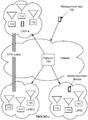
- a system 100 for enhanced mesh networking includes a plurality of mesh network capable routers 110, as shown in FIGURE 1 .
- the system 100 may additionally or alternatively include a router management platform 120 and/or a management application 130.
- the system 100 functions to enable seamless wireless coverage of an area (e.g., a user's home) using mesh networking while reducing the complexity of configuring such a network.
- a user must configure a first router to serve as a gateway to the internet (e.g., by connecting the router to a cable modem).
- some networking device generally the aforementioned first router
- NAT network address translation
- DHCP dynamic host configuration protocol
- wireless access point e.g., wireless routers, access points, repeaters
- the configuration options are virtually endless.
- the access points could exist on a single bridged network, or could be separated into different networks (e.g., could be assigned to different VLANs; that is, virtual local area networks).
- the access points could be connected to each other by Ethernet cables, or simply serve as wireless repeaters.
- the access points could share available Wi-Fi channel space in any number of ways.
- the system 100 preferably performs much of this configuration both automatically and dynamically-optimizing the network for a user's needs without requiring extensive computer networking knowledge or hassle.
- the mesh-network capable routers 110 are preferably multi-band (e.g., dual-band, tri-band, etc.) routers substantially similar to those described in U.S. Patent Application No. 15/008,251 . Additionally or alternatively, the routers 110 may be any suitable networking devices (e.g., smart access points).
- the routers 110 preferably include a Wi-Fi radio and a processor.
- the routers 110 can additionally or alternatively include a Bluetooth radio, an Ethernet interface, and/or any other suitable hardware or software.
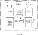
- a smart router includes two Wi-Fi radios: one 5GHz radio and one 2.4GHz radio, a Bluetooth radio capable of Bluetooth Smart communication, an auto-sensing gigabit Ethernet interface, an ARM processor, DDR RAM, EMMC storage (for router firmware), and a USB interface (e.g., for adding network-accessible storage).
- a smart router includes three Wi-Fi radios: two 5GHz radios and one 2.4GHz radio, a Bluetooth radio capable of Bluetooth Smart communication, an 802.15.4 radio (e.g., configured to communicate using one or more 802.15.4 protocols, such as Thread, ZigBee, etc.), an auto-sensing gigabit Ethernet interface, an ARM processor, DDR RAM, and EMMC storage (for router firmware).
- three Wi-Fi radios two 5GHz radios and one 2.4GHz radio
- a Bluetooth radio capable of Bluetooth Smart communication
- an 802.15.4 radio e.g., configured to communicate using one or more 802.15.4 protocols, such as Thread, ZigBee, etc.
- an auto-sensing gigabit Ethernet interface such as Thread, ZigBee, etc.
- ARM processor DDR RAM
- EMMC storage for router firmware
- a smart router includes two Wi-Fi radios: one 5GHz radio and one 2.4GHz radio, a Bluetooth radio capable of Bluetooth Smart communication, an 802.15.4 radio (e.g., configured to communicate using one or more 802.15.4 protocols, such as Thread, ZigBee, etc.), an ARM processor, DDR RAM, and EMMC storage (for router firmware).
- the smart routers can be any suitable router, wireless access point, and/or other networking device.
- the smart routers can include any suitable combination of any suitable radios (e.g., short-range radios such as NFC, RF, etc.), processing systems, sensor set, or other components.
- the Wi-Fi radio(s) preferably function to provide wireless access to the router 110.
- the Wi-Fi radio preferably serves to allow electronic devices (e.g., smartphones, laptops, gaming consoles) to communicate wirelessly with the router 110 and with each other through a LAN, as well as to allow routers 110 to communicate with each other over a mesh.
- Each Wi-Fi radio preferably includes at least one antenna; additionally or alternatively, the Wi-Fi radio may include an interface to connect to an external antenna.
- Antennas may be of a variety of antenna types; for example, patch antennas (including rectangular and planar inverted F), reflector antennas, wire antennas (including dipole antennas), bow-tie antennas, aperture antennas, loop-inductor antennas, ceramic chip antennas, antenna arrays, and fractal antennas.
- the Wi-Fi radio preferably supports communication over all of IEEE 802.11 a/b/g/n/ac standards (as well as the modified 802.11 s standard discussed later), but may additionally or alternatively support communication according to any standard (or no standard at all).
- the router 110 may include any number of Wi-Fi radios operating on any suitable frequency ranges.
- the router includes two or more Wi-Fi radios: one or more operable on the 2.4 GHz band and another one or more operable on one or more 5 GHz bands (e.g., 5.2 GHz band, 5.8 GHz band, 5 GHz bands requiring use of DFS, etc.).
- the router 110 may additionally include a switchable radio, enabling the router 110 to select from two different communication modes (2.4 GHz + 5 GHz or 5 GHz + 5GHz) in order to maximize connection quality.
- the Wi-Fi radios preferably operate using single-input/single-output (SISO) communication techniques, but may additionally or alternatively operate using multiple-input and/or multiple-output communication techniques (e.g., SIMO, MISO, MIMO). If the Wi-Fi radios operate using MIMO techniques, the Wi-Fi radios may use any type of MIMO techniques (e.g., precoding, spatial multiplexing, space-division multiple access, and/or diversity coding). Further, the Wi-Fi radios may perform MIMO communication either independently (e.g., a radio performs MIMO communication with multiple antennas coupled to that radio) or cooperatively (e.g., two separate radios perform MIMO communication together).
- SISO single-input/single-output
- the Bluetooth radio functions to allow devices to communicate with the router 110 over a connection mechanism alternative to Wi-Fi.
- the Bluetooth radio is preferably used to allow the router 110 to be configured for the first time by a smartphone (or other Bluetooth-enabled computing device).
- the Bluetooth radio may additionally or alternatively be used for any other purpose; for example, for configuring the router 110 at a different time, for communication between routers 110, or for communication with smart devices in a home (e.g., smart locks, light bulbs).
- the Bluetooth radio preferably supports the Bluetooth 4.0 standard, including communications capabilities for classic Bluetooth as well as Bluetooth Low-Energy (BTLE).
- BTLE Bluetooth Low-Energy
- the Bluetooth radio preferably switches between classic Bluetooth and Bluetooth Low-Energy, but may additionally or alternatively be capable of communicating over both simultaneously.
- the Bluetooth radio preferably includes at least one antenna; additionally or alternatively, the Bluetooth radio may include an interface to connect to an external antenna.
- Antennas may be of a variety of antenna types; for example, patch antennas (including rectangular and planar inverted F), reflector antennas, wire antennas (including dipole antennas), bow-tie antennas, aperture antennas, loop-inductor antennas, ceramic chip antennas, antenna arrays, and fractal antennas.
- the Ethernet interface functions to provide wired connectivity to the router 110.
- the Ethernet interface preferably allows wired devices (including other routers 110) to connect to the router 110.
- the Ethernet interface preferably includes a plurality of Ethernet ports. Ports of the Ethernet interface are preferably capable of 1000BASE-T (i.e., gigabit) communication, but may additionally or alternatively be capable of communication at any rate.
- the Ethernet interface preferably automatically sets the communication rate based on the capabilities of connected devices, but may additionally or alternatively set the communication rate manually.
- the router 110 may additionally or alternatively perform wired communication over any wired interface.
- the router 110 may perform communication through a powerline interface (e.g., Ethernet over Power).
- the router 110 preferably includes a microprocessor and may additionally or alternatively include any other hardware.
- the router 110 may include a USB interface (for connection of network-attached storage, a DLNA server, etc. or for configuration purposes).
- the router 110 includes a hardware encryption module (HEM).
- the HEM is preferably a chip that stores an encryption key securely (e.g., the Atmel SHA204) and performs data encryption based on that key, but may additionally or alternatively be any hardware module capable of encrypting transmissions from and/or decrypting transmissions to the router 110.
- the router 110 preferably stores firmware and/or software on an embedded MultiMediaCard (eMMC), but may additionally or alternatively store firmware and/or software in any suitable storage solution.
- eMMC embedded MultiMediaCard
- the router 110 preferably operates as a Linux server running Python programs, but may additionally or alternatively operate using any software and/or firmware.
- the router 110 is preferably configured using the management application 130 operating on a remote electronic device (e.g., a user's smartphone), but may additionally or alternatively be configured by any suitable manner (e.g., by a web interface).
- a remote electronic device e.g., a user's smartphone
- any suitable manner e.g., by a web interface
- the routers 110 preferably communicate with each other using one or more versions of the 802.11S protocol (e.g., the modified version described below), using Simultaneous Authentication of Equals (SAE)-based encryption and hybrid wireless mesh protocol (HWMP) path selection, but may additionally or alternatively communicate with each other in any manner.
- SAE Simultaneous Authentication of Equals
- HWMP hybrid wireless mesh protocol
- the routers 110 may perform routing functions (and/or be capable of performing routing functions), the routers 110 can additionally or alternatively include access points (e.g., wireless access points such as wireless mesh access points, etc.), repeaters, mesh nodes, switches, and/or any other suitable network devices.
- access points e.g., wireless access points such as wireless mesh access points, etc.
- repeaters e.g., repeaters, mesh nodes, switches, and/or any other suitable network devices.
- the routers 110 are preferably configured and/or managed by the router management platform 120 (or any suitable remote management platform).
- routers 110 may be configured by altering stored configuration profiles in a remote server (part of the router management platform 120), after which the stored configuration profiles are pushed to the routers 110. This technique is particularly useful in mesh networking applications; if the router management platform 120 is aware that three smart routers are intended for use in a single network, the router management platform 120 can attempt to bridge the networks of the three routers regardless of physical location or existing network topology.
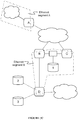
- the router management platform 120 may additionally function to manage connections and/or permissions associated with various networks. For example, a user of the router management platform 120 associated with one network may have guest permissions on another network (e.g., users of LAN1 may be granted permissions with respect to LAN2 via the platform). As another example, the router management platform 120 maybe used for (or may otherwise facilitate) bridging two networks via a VPN tunnel (e.g., two physical networks LANia and LAN1b into a single logical network), as shown in FIGURE 1 .
- a VPN tunnel e.g., two physical networks LANia and LAN1b into a single logical network
- the router management platform 120 may additionally or alternatively be used to collect connection data from the routers 110 and/or provide this data (or analysis of this data) to users either via the routers 110 or otherwise (e.g., via a web portal).
- the system 100 may additionally include a management application 130 that functions to manage routers 110 that are part of a network.
- the management application 130 is preferably a native application running on a smartphone (e.g., an iOS or Android application), but may additionally or alternatively be any suitable application (e.g., a web app, a desktop app, etc.).
- the management application 130 may be used to perform or aid in router 110 configuration, but may also be used to collect data used by the method 200.
- a management application operable on a device for which location data is desired may collect (and potentially analyzed and/or transmit) data that may be used to perform device localization.
- Routers 110 of the same LAN are preferably coupled together as a mesh network; e.g., the example network as shown in FIGURE 4 .
- Routers 110 may communicate to each other and/or to client devices (represented by the circle 'D' symbol) in any manner, e.g., 2.4 GHz Wi-Fi, 5 GHz Wi-Fi, Bluetooth, wired Ethernet.
- the system 100 preferably attempts to path information along the mesh in such a way as to enhance performance compared to traditional mesh networking architectures.
- the system 100 preferably attempts to enhance mesh networking performance by intelligently managing communication between network nodes (e.g., smart routers 110) and between devices communicating with those nodes (e.g., laptops, smartphones, TVs, etc.).
- network nodes e.g., smart routers 110
- devices communicating with those nodes e.g., laptops, smartphones, TVs, etc.
- Such management includes managing the characteristics of links from router to router and from router to device (e.g., channel, radio, broadcast time, etc.) as well as actively routing information across those links (e.g., attempting to identify optimal paths across the network for packets).
- a router 110 preferably attempts to make every link possible for the router 110 within the network. For example, a router 110 that sees four other routers 110 within its wireless range (on both 2.4 GHz and 5 GHz) may create eight links (one for each radio within range). The router 110 preferably adopts this approach because the cost for maintaining a link is relatively low compared to the cost of communicating on a link. Alternatively, the router 110 may not attempt to make every possible link. For example, if a router 110 has an Ethernet connection to another router 110, those two routers 110 may not link wirelessly to each other. As another example, in high density meshes, a router 110 may choose to connect only to a threshold number of routers 110 nearby (e.g., 15 routers of 30 total routers within range).
- the channels used by the radios of the routers 110 are preferably set to reduce interference across the network.
- two routers 110 near each other may use the same 5 GHz band (allowing those two routers to communicate with each other AND with devices, but potentially causing collisions for communication from client devices near both routers 110), but a different 2.4 GHz band (allowing client devices near both routers 110 to communicate to one router 110 without interfering with communication of other client devices to the other router 110).
- Router 110 channels may be orthogonal or overlapping.
- routers 110 near each other may choose different, but overlapping, 2.4 GHz bands, allowing those routers to still communicate with each other while also reducing client device interference.
- Router channels may be set in any manner.
- a first router 110 selects a 2.4 GHz channel (referred to as 2.4A) and a 5 GHz channel (5A) based on a radio survey.
- Each additional router 110 selects the same 5 GHz channel (5A) but selects the 2.4GHz channel based on a radio survey (e.g., trying to minimize 2.4GHz interference between routers 110).
- Router channels maybe set individually by routers 110, in concert by a set of routers 110, by the management platform 120, or by any other agent.
- Router channels may also be modified at any time.
- a router 110 having selected a channel by the technique described in the preceding paragraph may switch its 5 GHz channel in response to heavy traffic on that channel by client devices.
- the router 110 may additionally need to change its 2.4 GHz channel as well (as the router 110 may have to communicate with other nodes on the 2.4 GHz band now instead of the 5 GHz band, such as if the other nodes are not operating on its new 5 GHz channel).
- Routers 110 may additionally or alternatively attempt to modify any other parameters related to inter-router links. For example, routers 110 may adjust antenna patterns and/or gain to reduce network interference. Additionally or alternatively, routers 110 may perform beam-forming or beam-steering (potentially with dynamic gain) for the same purpose. Similar to channels, other router parameters may be set individually by routers 110, in concert by a set of routers 110, by the management platform 120, or by any other agent.
- Routers 110 When a device connected to a router 110 attempts to communicate with another device on the network (or via a gateway of the network), the router 110 preferably determines an optimal path for the communication to follow.
- Routers 110 preferably utilize IEEE 802.11s Hybrid Wireless Mesh Protocol (HWMP) and/or a modified version thereof (e.g., such as described below), but may additionally or alternatively use any technique for determining pathing.
- HWMP Hybrid Wireless Mesh Protocol
- a router 110 when a router 110 wants to send a packet to a destination, the router 110 first checks its routing table to see if it has a current path to the destination. If so, the router 110 forwards the packet to the next hop node. If not, the router initiates a path discovery process by creating a path request (PREQ) packet.
- PREQ path request
- This packet contains the source MAC Address, the HWMP sequence number of the originator, a path discovery ID, time-to-live (TTL) and Life Time fields, hop count, the destination MAC address, and a link metric.
- this PREQ packet is forwarded across a network until the destination is reached.
- the destination router(s) 110 send back a path reply (PREP) packet, similar to the PREQ packet.
- PREP path reply
- the link metric and hop count are updated as the packet moves along the network (essentially taking the path integral of those values).
- One or both of the link metric and hop count are used to determine, at the source router 110, the quality of the paths available.
- Default 802.11S implementations utilize a metric referred to as an "airtime link metric", defined as the total data transmission time (in time units) divided by one minus the frame error rate: T 1 ⁇ E . While the system 100 may use this metric (or any metric), the system 100 preferably uses a novel metric (herein referred to as a Bifrost metric). In contrast to the airtime link metric of 802.11s, the Bifrost metric accounts for (e.g., takes as input) factors such as data throughput (e.g., channel transmission rate) and channel utilization. The Bifrost metric can additionally include any other suitable factors (e.g., thermal throttling and/or enforced dead transmit time, such as described below).
- the Bifrost metric is determined based on one or more throughput metrics and channel utilization metrics (e.g., associated with wireless channels).
- the Bifrost metric (and/or underlying metrics associated with the Bifrost metric, such as throughput and/or channel utilization metrics) are preferably associated with (e.g., determined based on characteristics of) the links of the network (e.g., wireless links; wired links; aggregated groups of links, such as links sharing common endpoints; etc.), such as being determined independently for each link of a path within the network.
- the metrics can additionally or alternatively be associated with nodes, paths, physical regions, and/or any other suitable elements associated with the network.
- the metrics can be direction-specific (e.g., for link or path metrics, determined independently for each direction along the link or path) or direction-nonspecific (e.g., identical for a forward and reverse path, identical for a link from a first to a second device and a link from the second to the first device, etc.).
- the throughput metrics can include transmission and/or reception rates (e.g., data rates, frame rates, packet rates, etc.), and/or any other suitable throughputs.
- the throughput metrics are preferably metrics associated with (e.g., measured at) the physical layer, but can additionally or alternatively be associated with the data link layer, network layer, transport layer, and/or any other suitable layer (e.g., of the OSI layer model).
- the throughput metrics are preferably determined based on a filtered and/or otherwise processed version of the collected throughput data (e.g., low-pass filtering, Kalman filtering, Hamming windowing, etc.).
- the throughput metric can represent an average (and/or other statistical function, such as median) over time, such as a moving average (e.g., exponentially weighted moving average, triangle-number weighted moving average, Hull moving average, unweighted moving average, etc.).
- a moving average e.g., exponentially weighted moving average, triangle-number weighted moving average, Hull moving average, unweighted moving average, etc.
- the metrics can additionally or alternatively be substantially instantaneous metrics (e.g., associated with the most recently collected data), can represent maximum values (e.g., maximum attained in a particular time window), and/or can be processed in any other suitable manner.
- the throughput measurements can be sampled only during times when data transmission is being attempted (e.g., while data is queued for transmission, during transmission, etc.) or at all times (e.g., whether or not nodes are attempting to transmit data), and/or can be sampled at any other suitable times.
- a throughput metric is equal to T Xavg , the exponentially weighted moving average of the transmit throughput (e.g., from a node along a link) measured at the physical layer (TX PHY rate); R Xavg , the exponentially weighted moving average of the receive throughput (e.g., to the node along the reverse direction of the link) measured at the physical layer (RX PHY rate); and/or a combination thereof (e.g., sum, inverse sum, arithmetic and/or geometric mean, minimum or maximum of the two, etc.).
- the channel utilization metrics are preferably adjusted to represent utilization not attributable to the entity (e.g., node, link, path, etc.) for which the metric is calculated.
- the channel utilization metrics can additionally or alternatively include any other suitable adjustments (e.g., in place of or in addition to the T self term), and/or can be unadjusted (e.g., can exclude the T self term).
- the Bifrost metric is computed as follows: at each node, a base metric is computed as the inverse of a throughput metric D. The base metric is then modified by terms including a channel utilization metric U, preferably an adjusted channel utilization metric that represents the channel utilization not due to that node (e.g., amount of traffic on the channel not due to the node, fraction of time the channel is unavailable for the node to transmit on, etc.).
- a channel utilization metric U preferably an adjusted channel utilization metric that represents the channel utilization not due to that node (e.g., amount of traffic on the channel not due to the node, fraction of time the channel is unavailable for the node to transmit on, etc.).
- C some constant (e.g., kept fixed for all calculations of the metric M for all nodes and/or links, constant for a given node and/or link but varying between different nodes and/or links, etc.)
- T busy is time the channel was in use
- T self is time the channel was in use due to communication from the node itself
- T active is the time the total radio spent on the channel.
- this metric decreases with increasing throughput (i.e., faster connections result in lower metric values) and increases along with channel traffic (i.e., less traffic results in lower metric values).
- This metric also exhibits reduced sensitivity (e.g., is invariant to, changes less than a metric using an unadjusted channel utilization metric, etc.) contributions of the node measuring the metric to traffic.
- the Bifrost metric can optionally include one or more parameters representing hardware conditions, such as temporary performance restrictions.
- Radio throttling can be used, for example, to prevent and/or alleviate radio overheating (e.g., by reducing radio transmission time, thereby reducing the thermal energy generated by the radio).
- the Bifrost metric can include any other suitable hardware condition parameters in any other suitable manner.
- the Bifrost metric After the Bifrost metric has been calculated for a given link (e.g., defining the link cost), it's added to the sum of previous metrics along the path, such that the eventual metric becomes a path integral for Bifrost metric values along the path (e.g., defining the path cost). As described above, the path with the smallest Bifrost metric value is the 'best' path.
- nodes of a path each calculate a link metric for a link associated with the node (e.g., originating from or terminating at the node), receive a partial path metric (e.g., the cumulative sum of link metrics along a portion of the path, such as from the initial or terminal node to the node transmitting the partial path metric) from a neighboring node (e.g., next or previous node along the path), add the calculated link metric to the partial path metric, and transmit the new partial path metric to the opposing neighbor (e.g., continuing along the path or the reverse path).
- a link metric e.g., the cumulative sum of link metrics along a portion of the path, such as from the initial or terminal node to the node transmitting the partial path metric
- a neighboring node e.g., next or previous node along the path
- the terminal node of a path transmits (e.g., in response to receiving a path request) a path reply frame, preferably including a metric field (e.g., set to zero) to the previous node along the path (node B).
- node B determines the Bifrost link metric associated with the link from itself to node A (B-A link), updates the partial path metric by adding the link metric to the value from the metric field, and transmits an updated path reply frame (e.g., including the updated partial path metric) to the previous node along the path (node C).
- node C calculates the C-B link metric, updates the partial path metric, and transmits a path reply including the updated metric (representing the cost from C to A via B) to the previous node along the path.
- the path reply is propagated back to the initial node of the path.
- any node can optionally ignore or otherwise act upon receipt of a path reply (e.g., based on its metric).
- a first node receives two path replies for path segments from the first node to a second node, each via a different path (e.g., different series of intermediary nodes), it can optionally propagate the path reply with the better (e.g., lower) metric and ignore the path reply with the worse metric (e.g., as shown in FIGURE 5C ).
- the better e.g., lower
- the worse metric e.g., as shown in FIGURE 5C
- a client device attempts to send information to a cable modem on a mesh network having link metric values (e.g., link costs, such as costs which can be added to determine a path cost) as shown.
- link metric values e.g., link costs, such as costs which can be added to determine a path cost
- the node connected directly to the client device e.g., the AP for the client device
- PREQ path request
- the node connected directly to the client device e.g., the AP for the client device
- PREQ path request
- the gateway node In response to receiving the path request from each neighbor, the gateway node sends a path reply (PREP) message to the neighbor from which the PREQ was received, including a path metric (e.g., zero in all cases, because the path begins at the gateway node).
- PREP path reply
- Each node receiving a PREP calculates the link metric associated with the node from which the PREP was received (e.g., the link cost for transmitting from itself to the node from which the PREP was received), adds the link metric to the path metric in the received PREP, and propagates the PREP (with the updated path metric) along the reverse path (e.g., as shown in FIGURE 5C ).
- the node connected directly to the client device receives one or more PREPs, calculates and adds the final link metric, and selects the path with the lowest total metric (e.g., as shown in FIGURE 5D ). Communication from the client device to the cable modem maybe routed along this path.
- the Bifrost metric preferably increases with (e.g., is directly proportional to) the airtime cost of queueing a given unit of data on a particular peer link, and is preferably comparable across link frequency (e.g., 2.4 and 5 GHz).
- the Bifrost metric can account for Ethernet link quality, allowing comparisons not just across link frequency but also across wired and wireless links as well.
- the Bifrost metric can additionally or alternatively be set equal to zero (e.g., representing a no-cost link) or a small constant for Ethernet links, and/or can treat Ethernet links in any other suitable manner (or not be applied for Ethernet links).
- the mesh network includes multiple links between the same nodes, such as for nodes with multiple link interfaces (e.g., multiple radios capable of independent, simultaneous communication, multiple Ethernet ports, both radios and Ethernet ports, etc.).
- multiple link interfaces e.g., multiple radios capable of independent, simultaneous communication, multiple Ethernet ports, both radios and Ethernet ports, etc.
- two nodes can be simultaneously connected by multiple wireless links (e.g., in different bands, such as 2.4 GHz, 5.2 GHz, and/or 5.8 GHz) and/or Ethernet links.
- each of these physical links can be treated independently (e.g., a link metric can be determined for any or all of them independently; paths through the network can specify the physical links individually, rather than just the endpoints of the links; etc.).
- multiple physical links sharing endpoints can be considered (e.g., from a link assessment and/or path selection perspective) as a single effective link (e.g., treated as a link aggregation group), wherein a single link metric associated with the effective link is determined, and paths specify the effective link rather than any of the specific underlying physical links within it.
- This variation can enable individual mesh nodes (and/or linked pairs of nodes) to select the optimal physical link(s) for communication with a given neighbor, without interfering with higher-level path selection (e.g., including enabling multiplex communication with the neighbor).
- each node of an effective link is specified by a single identifier such as a MAC address (e.g., highest or lowest MAC address; MAC address of the first-connected physical link; MAC address associated with a predetermined interface, such as a first Ethernet port or first wireless radio of the node, optionally even if the effective link does not include a physical link associated with the predetermined interface; etc.).
- a MAC address e.g., highest or lowest MAC address; MAC address of the first-connected physical link; MAC address associated with a predetermined interface, such as a first Ethernet port or first wireless radio of the node, optionally even if the effective link does not include a physical link associated with the predetermined interface; etc.
- the effective link metric (e.g., link cost) associated with the effective link is preferably determined based on the physical link metrics of all or some of the underlying physical links.
- the effective link metric can be equal to the best physical link metric, the sum of the physical link metrics, the inverse sum (e.g., inverse of the sum of the inverses) of the physical link metrics, the arithmetic and/or geometric mean of the physical link metrics, and/or any other suitable function of the physical link metrics (or of a subset thereof, such as the best two or three such links).
- the effective link metric can additionally or alternatively be determined based on performance of the effective link (e.g., simultaneous use of multiple physical links of the effective link) rather than individual performance of the underlying physical links. However, the effective link metric can additionally or alternatively be determined in any other suitable manner.
- routers 110 include an autoprobing system triggered by Bifrost metric values. Because links that are idle or have 'bad' metrics may not see substantial traffic, nodes connected via these links may not receive regular metric updates (and therefore may not necessarily have the ability to modify configuration settings iteratively to improve metric values).
- the autoprobing system functions to generate traffic on links that are idle (e.g., below some activity threshold) and/or 'bad' (e.g., Bifrost metric below some threshold).
- the system 100 may utilize a learned (or otherwise tuned) link metric that, in aggregate, promotes a particular goal across the network.
- a learned link metric may be set based on the average latency across a network.
- Tuning the learned link metric may include utilizing one or more of: supervised learning (e.g., using logistic regression, using back propagation neural networks, using random forests, decision trees, etc.), unsupervised learning (e.g., using an Apriori algorithm, using K-means clustering), semi-supervised learning, reinforcement learning (e.g., using a Q-learning algorithm, using temporal difference learning), and any other suitable learning style.
- supervised learning e.g., using logistic regression, using back propagation neural networks, using random forests, decision trees, etc.
- unsupervised learning e.g., using an Apriori algorithm, using K-means clustering
- semi-supervised learning e.g., using a Q-learning algorithm, using temporal difference learning
- reinforcement learning e.g., using a Q-learning algorithm, using temporal difference learning
- Each module of the plurality can implement any one or more of: a regression algorithm (e.g., ordinary least squares, logistic regression, stepwise regression, multivariate adaptive regression splines, locally estimated scatterplot smoothing, etc.), an instance-based method (e.g., k-nearest neighbor, learning vector quantization, self-organizing map, etc.), a regularization method (e.g., ridge regression, least absolute shrinkage and selection operator, elastic net, etc.), a decision tree learning method (e.g., classification and regression tree, iterative dichotomiser 3, C4.5, chi-squared automatic interaction detection, decision stump, random forest, multivariate adaptive regression splines, gradient boosting machines, etc.), a Bayesian method (e.g., naive Bayes, averaged one-dependence estimators, Bayesian belief network, etc.), a kernel method (e.g., a support vector machine, a radial basis function, a linear discriminate analysis, etc.),
- Each processing portion of the method 200 can additionally or alternatively leverage: a probabilistic module, heuristic module, deterministic module, or any other suitable module leveraging any other suitable computation method, machine learning method or combination thereof.
- a probabilistic module e.g., a probability density function
- heuristic module e.g., a probability density function
- deterministic module e.g., a probability density function
- any suitable machine learning approach can otherwise be incorporated into link metric learning.
- multicast and broadcast frames transmitted by the routers 110 preferably include an additional field specifying the band and/or channel (e.g., and/or the radio, such as a radio associated with a particular band) on which a router 110 saw a path announcement (e.g., path request or PREQ, path reply or PREP, etc.).
- a path announcement e.g., path request or PREQ, path reply or PREP, etc.
- passing an announcement from one radio, band, and/or channel to another on the same node would result in a change of the sequence number. Consequently, the message is now treated differently by the network, and loops may occur.
- the system 100 can allow paths containing links in multiple bands without suffering the looping issues present in the 802.11S implementation.
- some or all frames may not include this additional field.
- routers 100 preferably hash a portion (e.g., unique portion) of the frame (e.g., the source address of the frame and/or packet header, the entire frame and/or packet header, the frame and/or packet contents, the entire frame and/or packet, etc.) and store the hash along with an expiration timer.
- a portion e.g., unique portion
- the router 100 preferably maintains a list of the several most recent multicast frames received from each source (e.g., 16) along with a TTL value and an expiration time. If the router 100 receives a multicast frame from a source within the expiration time of a record stored with that router 100, the router 100 decrements the stored TTL and forwards the frame. When the stored TTL reaches zero, the frame will be discarded instead of forwarded. As each node has an RCU protected hash table of these lists, lookup is easily parallelizable, providing efficiency gains over standard 802.11S implementations.
- This multicast cache maybe shared between wireless and wired interfaces, preventing loops and enabling both wired and wireless connections to be used in the network.
- the system 100 includes an additional layer on top of the link metric system described above.
- routers 110 maintain a distributed Quality of Service (QoS) based system where a given router 110 will issue traffic credits to other nodes in their wireless collision domain. These traffic credits may place restrictions on when neighboring nodes can send data to a router 110, allowing the system 100 to reduce collisions in a coordinated fashion.
- QoS Quality of Service
- the system 100 may utilize machine learning to distribute and/or regulate traffic credits in such a system.
- the system 100 preferably uses link metrics for routing as described above, but the system 100 may additionally or alternatively use calculated link metric values as a proxy for live throughput values as an estimation of network health.
- the system 100 may additionally or alternatively use link metric values to estimate network health in any manner.
- the system 100 may additionally or alternatively perform techniques to force client devices to move access points. This may be useful, for example, to better distribute client devices across wireless access points (APs). For many mobile electronic devices (e.g., most smartphones), device users (and APs, for that matter) have very little control over how the device chooses a wireless network. In most cases, wireless clients connect to a network and remain connected to it until signal quality (or another metric of communication quality) drops below a static threshold, at which point the clients disconnect and search for the strongest signal.
- signal quality or another metric of communication quality
- Forcing a client disconnect preferably causes such a device to re-check what the strongest AP is and connect to it.
- AP signal strength is correlated with distance from the AP, interference and noise may mean that the strongest AP is not necessarily the closest.
- a smartphone is in a living room near a wall, and the living room AP is ten feet away.
- a bedroom, having a bedroom AP is on the other side of the wall. In such a situation (based in part on attenuation due to the wall), the smartphone may see the living room AP as "closer" (i.e., it sees a higher signal strength).
- Forcing a client connection change may have numerous changes beyond localization, including optimization of mesh networking parameters, network load balancing, and/or wireless interference management.
- a client in order to enhance network performance, a client can be forced to disconnect from a first AP and to instead connect to a second AP, even if the client-second AP link is worse (e.g., associated with lower throughput) than the client-first AP link.
- the path cost from the first AP to the internet is much higher than the cost from the second AP to the internet, such that the overall client-internet path cost is lower when the client is connected to the second AP.
- the link between the first AP and a second client can be improved by disconnecting the first client from the first AP (e.g., thereby enabling strong beamforming to enhance the quality of the second client-first AP link).
- client connection changes can additionally or alternatively be controlled in any other suitable manner for any other suitable reason.
- a router 110 may force a client connection change in any manner.
- the router 110 may remove a client from an access point by blocking the MAC address (or another identifier) of the client at the access point and actively kicking the client off of the access point; this prevents the client from reconnecting until the MAC address is unblocked.
- the router 110 may disconnect a client from an AP without preventing the client from rejoining that AP.
- a router 110 may rescind credentials for a particular device.
- the router 110 may include rescind credentials in any manner; for example, by rescinding access to an AP using a set of credentials associated with the device or with a user of the device.
- these credentials may be device or user specific (e.g., a certificate stored on a smartphone, a username/password) but additionally or alternatively, the credentials may be non-device-specific (e.g., an AP password for a WPA-2 personal secured AP).
- the router 110 may additionally or alternatively disconnect a client from an AP in any other manner (e.g., by lowering transmit power of the AP to force client roaming).
- the system 100 may, by controlling the access points a client can connect to, force a client to connect to a specific AP (or one of a set of APs).
- a mesh network may include four APs within range of a device: AP1, AP2, AP3, and AP4. By blocking the device from connecting to AP1 and AP2, the network may force the device to connect to one of AP3 or AP4. Likewise, AP3 could also be blocked to force the device to connect to AP4.
- the preceding examples are operable even when APs have limited control over client roaming. However, in some cases, a network may have more substantial control over client roaming (or may even be able to designate which network the device connects to explicitly). In these cases, the system 100 may additionally or alternatively modify client roaming parameters and/or direct the device to connect to a specific AP or a set of APs.
- the system 100 may direct AP modification in any manner.
- routers 110 may store link quality metrics for the links between APs and client devices, and may disconnect client devices if they fall below a threshold.
- routers 110 may evaluate client links by latency to the client (this latency may be scaled based on the type of client device).
- the system 100 may attempt to distribute clients among routers 110 (and radios of those routers 110) based on any number of factors, including the type of device (e.g., smartphone, laptop, etc.), model of device (e.g., Galaxy, iPhone), bandwidth usage of device (e.g., high bandwidth, low bandwidth), mobility of device (e.g., as determined by RSSI changes or by AP changes), frequency of communication, etc.
- type of device e.g., smartphone, laptop, etc.
- model of device e.g., Galaxy, iPhone
- bandwidth usage of device e.g., high bandwidth, low bandwidth
- mobility of device e.g., as determined by RSSI changes or by AP changes
- frequency of communication e.g., Wi-Fi, Wi-Fi, etc.
- the system 100 may additionally or alternatively distribute client devices based on contextual or historical data. For example, a computer used during the day for large downloads and at night for gaming may be switched between a connection (e.g., a wireless link to an AP, a path through the network to the internet, etc.) having high throughput and/or high latency (during the day) and one having low throughput and/or low latency (during the evening).
- a connection e.g., a wireless link to an AP, a path through the network to the internet, etc.
- the system 100 may perform sharing traffic across multiple internet connections.
- the system 100 may designate primary and secondary (and tertiary, and so on) internet connections, used by all devices on a particular network.
- the system 100 may additionally or alternatively designate internet connections by device (e.g., all devices in the 192.168.1.xxx subnet use a particular connection, all smartphones use a particular connection, etc.), or by TCP stream (or at any other sub-device resolution level); for example, high bandwidth, latency insensitive applications (e.g., streaming video) may use a first connection, while low bandwidth, latency sensitive applications (e.g., real-time online gaming) may use a second connection.
- device e.g., all devices in the 192.168.1.xxx subnet use a particular connection, all smartphones use a particular connection, etc.
- TCP stream or at any other sub-device resolution level
- high bandwidth, latency insensitive applications e.g., streaming video
- low bandwidth, latency sensitive applications e.g., real-time online gaming
- Traffic sharing may be performed based on any suitable input data.
- traffic sharing may include altering NAT configuration based on available bandwidth (e.g., a particular connection is only used until a bandwidth cap is reached), price (e.g., expensive connections may be used only when necessary for a particular application), or any other criteria.
- Traffic sharing agreements are preferably determined by the router management platform 120, but may additionally or alternatively be determined by any suitable entity.
- Traffic sharing can also be accomplished via network load balancing algorithms, whereby IP traffic is distributed over the multiple internet connections in order to meet one or more network goals.
- network goals may include reducing response time for one or more devices on the network, increasing bandwidth available to one or more devices on the network, increasing performance for particular services or types of traffic on the network, increasing reliability of internet access for devices on the network, etc.
- a first example of a network load balancing algorithm for traffic sharing is a round robin algorithm. The round robin algorithm allocates a first IP traffic request to a randomly selected first internet connection, a second traffic request to a second internet connection that is randomly selected except that it excludes the first, and so on until all internet connections have been allocated at least once, at which point the cycle repeats.
- Round robin works well when most traffic requests are roughly equal in bandwidth demand and duration.
- a second example of a network load balancing algorithm is dynamic round robin. Dynamic round robin works similarly to the base round robin algorithm except that the allocation step is distributed according to a weighting scheme discerned from real-time internet connection performance. Dynamic round robin can eschew the problem of multiple high traffic requests being routed over the same internet connection.
- a third example of a network load balancing algorithm is a predictive algorithm.
- a predictive algorithm can monitor real-time internet connection characteristics (e.g., which internet connections have the fewest IP traffic requests on them, which internet connections have the largest data stream allocations on them, etc.) and historical internet connection characteristics (e.g., a time series of monitored download and upload speeds over a recent time period) in order to determine which internet connections are improving or declining in performance over time (as quantified in a metric of performance), can feed these metrics of performance into a dynamic weighting scheme, and can allocate new IP traffic requests according to the dynamic weighting scheme.
- any suitable network load balancing algorithm can be implemented by the system 100.
- the manner in which the system 100 performs load balancing can be predetermined (e.g., traffic can be proportionally distributed across internet connections), dynamically determined (e.g., at the time of a user request, the particular request can assign a priority, and then the routers can handle load performance in accordance with the priority hierarchy of all network traffic), or determined in any other suitable manner.
- Embodiments of the method 200 can optionally implement some or all of the network assessment and/or management techniques described above regarding the system 100. Such techniques are preferably performed using the system 100, but can additionally or alternatively be performed using any other suitable network or other system.
- a method 200 for enhanced mesh networking preferably includes performing network analysis S210, configuring router link parameters S220, and managing routing paths S230, as shown in FIGURE 6 .
- the method 200 may additionally or alternatively include managing client links S240 and/or any other suitable elements.
- the method 200 preferably functions to effectively configure and manage a mesh network (e.g., a network operating on multiple frequency bands, and potentially bridged by Ethernet links) by efficiently assigning router communication parameters and determining routing paths based on discovered link metrics.
- a mesh network e.g., a network operating on multiple frequency bands, and potentially bridged by Ethernet links
- the method 200 is preferably performed by the system 100, but may additionally or alternatively be performed by any mesh network (e.g., any multi-band mesh network).
- any mesh network e.g., any multi-band mesh network.
- S210 includes performing network analysis.
- S210 functions to determine network state information.
- S210 may function to determine the number of mesh nodes (e.g., routers) in a network, individual configuration details for each node (e.g., wireless communication channels, channel width, Ethernet capabilities, wireless mode, encryption type, QoS configuration, DHCP configuration, NAT configuration), their proximity to one another, the connection type and quality between nodes, the number of client devices in a network, individual configuration details for each client device (e.g., client type, client AP, client wireless communication channel, client Ethernet capabilities), connection type and quality between clients and nodes, overall network throughput, WAN gateway details, etc.
- mesh nodes e.g., routers
- individual configuration details for each node e.g., wireless communication channels, channel width, Ethernet capabilities, wireless mode, encryption type, QoS configuration, DHCP configuration, NAT configuration
- connection type and quality between clients e.g., client type, client AP, client wireless communication channel, client Ethernet capabilities
- S210 may include performing network analysis in any manner.
- S210 may include querying devices on the network, performing network surveys from devices on the network, requesting user input, or any other technique.
- S210 may additionally or alternatively include logging network data and using this data to perform network analysis.
- S210 may including logging link (either inter-router links or client-router links) throughput and error rate to determine link quality.
- S210 is preferably performed by one or more routers of a mesh network, but may additionally be performed by or aided in performance by a mobile client device (e.g., a smartphone) running a network monitoring app.
- S210 may include collecting network data from a smartphone as a user moves around in a mesh network.
- S210 may additionally or alternatively include requesting network analysis data from a network user.
- S210 may include asking a user to notify a management app on a client device if the network is ever not working ideally (triggering the network to log data particular to the client device and/or time).
- S210 is preferably run during initial network configuration, but may additionally or alternatively be run at any time in order to better inform network configuration.
- S220 includes configuring router link parameters. S220 functions to configure communication links between routers.
- S220 For each mesh node, S220 preferably includes initializing links to every other mesh node within communications range. These links may then be used (or not used) depending on routing needs. Additionally or alternatively, S220 may include initializing links to only a subset of mesh nodes within communication range. For example, S220 may include initializing links only to nodes of a certain type, nodes with a signal-to-noise (SNR) above some threshold, nodes with a Rx/Tx throughput above some threshold, nodes not connected via Ethernet, etc. As a second example, if there are m nodes within range of the node, S220 may include initializing links to n of m nodes based on some criteria (e.g., the five nodes with lowest latency).
- SNR signal-to-noise
- S220 may additionally or alternatively include modifying wireless communication channels of mesh nodes.
- S220 preferably includes setting wireless channels to reduce interference and increase throughput of the network, but may additionally or alternatively set wireless channels to achieve any goal.
- S220 may include, for example, setting nodes initially to the same 5 GHz channel, but setting nodes to diverse 2.4 GHz channels. Such a configuration may enable nodes to communicate with each other (and potentially client devices) over the 5 GHz band, while optimizing the 2.4 GHz band to communicate with client devices.
- S220 includes determining D c 2.4 (the percentage of airtime arising from router-client communication on the 2.4 GHz band), D c 5 (the percentage of airtime arising from router-client communication on the 5 GHz band), D m 2.4 (the percentage of airtime arising from router-router communication on the 2.4 GHz band), and D m5 (the percentage of airtime arising from router-router communication on the 5 GHz band) for each node of the network, as well as P 2.4 and P 5 (signal proximity; e.g., as measured by beacon SNR).
- D c 2.4 the percentage of airtime arising from router-client communication on the 2.4 GHz band
- D c 5 the percentage of airtime arising from router-client communication on the 5 GHz band
- D m 2.4 the percentage of airtime arising from router-router communication on the 2.4 GHz band
- D m5 the percentage of airtime arising from router-router communication on the 5 GHz band
- K 8 are constants
- This metric is minimized when nearby nodes with a lot of router-client communication on a given band are on different channels and when nearby nodes with a lot of router-router communication on a given band are on the same channel.
- this metric may be evaluated iteratively according to any minimization algorithm.
- S220 may include setting network channels by randomly varying channel settings (or otherwise varying channel settings) and monitoring network performance using a machine learning algorithm, eventually learning an optimal network channel state.
- S220 may additionally or alternatively include restricting traffic on a particular band for a particular purpose.
- S220 may include, on a given node, limiting 5 GHz traffic to backhaul traffic and 2.4 GHz traffic to router-to-device traffic.
- S220 may additionally or alternatively include attempting to modify any other parameters related to inter-router links. For example, S220 may adjust antenna patterns and/or gain to reduce network interference. Additionally or alternatively, S220 may include configuring nodes to perform beam-forming or beam-steering (potentially with dynamic gain) for the same purpose.
- S230 includes managing routing paths.
- S230 functions to determine paths across the network (e.g., across the mesh and/or Ethernet links) for a given source and destination.
- S230 preferably includes managing routing paths according to the IEEE 802.11s Hybrid Wireless Mesh Protocol (HWMP) (e.g., according to a modified version of the protocol, such as the modified versions described above regarding the system 100), but may additionally or alternatively use any technique for determining pathing.
- HWMP Hybrid Wireless Mesh Protocol
- S230 may, for example, include creating and/or updating routing paths using reactive and/or proactive routing techniques as described in the IEEE 802.11S standard, with the same deviations from this standard as described in the system 100 sections on pathing.
- S230 preferably includes maintaining at each node a multicast frame dataset, the dataset containing historical multicast information for each source.
- the dataset may contain references to the 16 most recent multicast frames for each source seen by the node. Each reference is preferably linked to a time stamp; if the difference in time between frames from the same source is below a threshold, the second frame may not be forwarded by the node.
- the dataset may maintain TTL for each entry (e.g., so if subsequent frames (such as a second frame, third frame, fourth frame, etc.) are received less than the threshold time after a first frame, each forward decrements TTL, and not all frames may be forwarded).
- This multicast cache is preferably stored as an RCU protected hash table, leading to easily parallelizable lookup and providing efficiency gains over standard 802.11S implementations. Likewise, this cache is preferably shared across communication modalities.
- S230 preferably includes determining routing paths using the Bifrost metric described in the sections on the system 100, but may additionally or alternatively utilize any suitable link metric(s).
- S230 can optionally include implementing the STAMP technique described below, but can additionally or alternatively use any other suitable techniques to enable incorporation of Ethernet segments (e.g., including legacy Ethernet devices incompatible with typical mesh networks) into the mesh network, or can use no such technique.
- S230 includes routing traffic according to a distributed Quality of Service system, where nodes issue traffic credits to other nodes in their wireless collision domain. These traffic credits may place restrictions on when neighboring nodes can send data to a node, allowing the network to reduce collisions in a coordinated fashion.
- the method 200 may additionally or alternatively include estimating network health and/or throughput based on the overall link metrics of the network.
- the method 200 may include measuring the network's total throughput, or a weighted average of throughput per node (weighted by node importance and/or traffic).
- S240 includes managing client links.
- S240 may include modifying any aspect of node-to-client-device communication; for example, QoS parameters, connection type (e.g., 802.11g vs. n vs. ac), connection modality (e.g., Ethernet vs. Wi-Fi vs. Bluetooth), connection speed, etc.
- connection type e.g., 802.11g vs. n vs. ac
- connection modality e.g., Ethernet vs. Wi-Fi vs. Bluetooth
- S240 may additionally or alternatively include optimizing client links by moving client devices from one node to others. This may be used to more evenly distribute client devices according to bandwidth availability and interference likelihood. Note that the same algorithms used to determine channels may also be used with varying client AP connections. For example, the previous formulae f 5 + f 2 .
- S240 may include forcing a client disconnect, preferably causing such a device to re-check what the strongest AP is and connect to it.
- forcing a client connection change may have numerous changes beyond localization, including optimization of mesh networking parameters, network load balancing, and/or wireless interference management.
- S240 may include forcing client connection changes in any manner, as discussed in the sections covering the same techniques in the description of the system 100.
- S240 preferably includes distributing clients across nodes in a manner that maximizes both overall network throughput and reliability as well as performance for individual devices on the network.
- S240 may include distributing clients across nodes based on any number of factors, including the type of device (e.g., smartphone, laptop, etc.), model of device (e.g., Galaxy, iPhone), bandwidth usage of device (e.g., high bandwidth, low bandwidth), mobility of device (e.g., as determined by RSSI changes or by AP changes), frequency of communication, historical connection quality data, historical bandwidth usage, etc.
- type of device e.g., smartphone, laptop, etc.
- model of device e.g., Galaxy, iPhone
- bandwidth usage of device e.g., high bandwidth, low bandwidth
- mobility of device e.g., as determined by RSSI changes or by AP changes
- frequency of communication e.g., historical connection quality
- S240 may additionally or alternatively include requesting manual user intervention.
- S240 may include directing a user to rotate and/or relocate one or more nodes of the network in order to increase network efficiency.
- S240 may additionally or alternatively include requesting any type of user network configuration intervention (including providing instructions for changing network device configurations in software, rerouting Ethernet cables, moving wireless access points, etc.).
- S240 preferably enables the user (most preferably by means of software operating in conjunction with a remote management platform, but alternatively otherwise) to easily implement the desired configuration changes.
- the user can confirm that the network configuration performed by the earlier steps are appropriate.
- the user is given instructions through software on an external electronic device; per the instructions, the user can then reconfigure network configuration settings when the reconfiguration includes physical modifications to network features (e.g., disconnecting routers which were previously physically tethered by an Ethernet cable).
- the method 200 (and/or any suitable elements thereof) can be performed once, repeatedly (e.g., periodically, sporadically, in response to trigger occurrence, etc.), and/or with any other suitable timing.
- the method 200 can include continuously assessing link metrics and repeatedly (e.g., periodically, in response to PREQ receipt, etc.) re-determining routing paths based on the metrics.
- Ethernet devices with more than one Ethernet port including switches, routers, bridges and client devices contain a structure generally referred to as an address resolution list or forwarding database. These devices use this ARL or FDB in order to quickly determine which of their multiple ports leads to a given MAC.
- ARL or FDB In order to quickly determine which of their multiple ports leads to a given MAC.
- Ethernet frames only contain two addresses-destination and source- and the Ethernet protocol is connectionless, the only means of determining where a given MAC is located on an Ethernet network is by snooping the source address of frames coming from that port.
- a traditional Ethernet switch upon receiving a frame, compares it to the addresses currently in its ARL, and if it finds it, will then deliver it to the port noted in the ARL. If it does not find the frame, it will flood it to every port other than the one it came in on. Having done this, it notes that the source address on the frame is present on whichever port it came in on.
- Spanning Tree Protocol which is designed to make a network acyclic, may not be a good fit for such networks, even if it is extended to handle mesh links on a per-peer-link basis.
- Segment Table Announced Mesh Protocol (e.g., Spanning Tree Announced Mesh Protocol) is an adjunct protocol which builds upon facilities provided by the IEEE 802.11S mesh networking standard in order to make it possible to deterministically deliver frames from mesh networks to legacy IEEE 802.3 Ethernet clients.
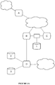
- STAMP preferably includes determining one or more segments of the network (e.g., the LAN).
- Each segment is preferably a portion of network-connected devices that are mutually connected by a homogeneous connection type (e.g., wherein all devices of a wireless segment are connected by wireless links, all devices of an Ethernet segment are connected by Ethernet, etc.), such as shown in FIGURES 7B-7C .
- the segments can be connected by heterogeneous connection types, multiple connection types (e.g., wired and wireless), or by any other suitable set of connections.
- the segments do not necessarily correspond to broadcast or collision domains.
- the entire network e.g., including multiple segments, such as two wireless mesh segments bridged by an Ethernet segment
- can define a single broadcast domain or alternatively, can include multiple broadcast domains, such as VLANs defined independent of the segments), and a single segment can include multiple collision domains (and/or collision domains can extend into multiple segments).
- Each segment preferably includes all devices reachable by links of similar type (e.g., reachable using only wireless links or only Ethernet links). However, the segments can alternatively exclude some such devices.
- segment definition can include a link quality threshold, wherein links below a threshold quality (e.g., threshold link metric value, such as a Bifrost metric value) are not ignored (e.g., devices connected only by such a link would not be considered to be in the same segment).
- threshold link metric value e.g., such as a Bifrost metric value
- wireless segments can exclude wireless links between nodes that are also connected by Ethernet (e.g., wherein the wireless segment is limited to devices that must communicate with each other wirelessly, rather than including all devices that can communicate with each other wirelessly).
- the method includes assessing (e.g., determining a link metric for) the Ethernet links between such nodes, wherein the associated wireless link is only excluded if the Ethernet link metric is better than a threshold (e.g., better than the wireless link metric, better than a predefined threshold, etc.).
- a threshold e.g., better than the wireless link metric, better than a predefined threshold, etc.
- each segment can be arbitrarily divided into sub-segments. For example, a segment can be divided into a number of sub-segments equal to the number of potential forwarding devices in the segment, wherein each potential forwarding device is designated as the forwarding device for a different sub-segment.
- the segments can additionally or alternatively be defined in any other suitable manner.
- Determining the segments preferably includes identifying each Ethernet segment and each wireless segment. However, determining the segments can additionally or alternatively include identifying only Ethernet segments, identifying only wireless segments, identifying only a subset of such segments, and/or determining any other suitable segments. Determining the segments can optionally include determining the members (e.g., connected devices) of some or all of the identified segments.
- the segments are preferably determined by the mesh nodes, such as by STAMP-capable nodes that are both in a mesh segment and in an Ethernet segment (e.g., nodes that connect a mesh segment to an Ethernet segment).
- the network does not include any mesh nodes that also have Ethernet connections but are not STAMP-capable, but alternatively the network can include any suitable nodes.
- STAMP uses the IEEE 802.1d Spanning Tree Protocol to map the Ethernet segments (e.g., wired Ethernet segments) attached to each node, making their topologies acyclic in the ordinary manner (e.g., the manner specified by STP).
- STP determines a unique "root bridge address" for each contiguous Ethernet segment.
- Another embodiment of STAMP propagates other messages (e.g., in addition to or in place of STP messages) in order to identify the Ethernet segments and/or their members.
- the STAMP-capable nodes are preferably configured not to send STP messages and/or any other Ethernet segment mapping messages into the mesh segments. Thus, such messages will propagate only within a single Ethernet segment (e.g., will not propagate through the wireless mesh), enabling the technique to distinguish between two non-contiguous Ethernet segments.
- mesh networks do not have an equivalent of a root node address that can be used to identify them. Instead, contiguity of mesh networks may be determined by having each STAMP-capable node (or a subset thereof, such as each node connected both to an Ethernet segment and a wireless segment) send a broadcast message (the "STAMP announcement") into the wireless segment to which it is connected.
- the STAMP announcement preferably includes the identifier (e.g., as described above) of the wired Ethernet segment the sending node is connected to, as well as an identifier associated with the sending node (e.g., sending node MAC address).
- broadcast messages are preferably tagged with a special ethertype
- STAMP-capable nodes are preferably configured to drop messages with the special ethertype at the mesh boundary (e.g., configured not to forward them to Ethernet segments); that is, it does not propagate outside of the wireless mesh.
- STAMP-capable nodes receive these STAMP announcement messages and build a list of every Ethernet segment visible from their mesh, wherein each Ethernet segment is associated with an identifier (e.g., the root bridge address, the highest or lowest MAC address of the Ethernet devices in the segment, etc.), and determine from the identifiers (e.g., the announced root bridge addresses) which mesh nodes are members of the same Ethernet segments.
- an identifier e.g., the root bridge address, the highest or lowest MAC address of the Ethernet devices in the segment, etc.
- the STAMP announcements can optionally include one or more STAMP metrics, such as metrics associated with the sending node. These metrics preferably include a network segment centrality and/or connectivity metric (e.g., representing how good the node's connection to the rest of the mesh segment is).
- the STAMP metric of a node is determined based on the peer links of the node (e.g., all wireless peer links within the mesh segment, all Ethernet peer links, all peer links of any type, etc.), such as being equal to the sum of the bitrates of the peer links or equal to the number of peer links.
- the STAMP metric is determined based on one or more HWMP metrics associated with the node, such as the metrics described above regarding the system 100 (e.g., Bifrost metrics, learned and/or tuned metrics, etc.).
- the STAMP metric of a node can be equal to the average of the path metrics between the node and each other member of the wireless segment (e.g., simple average, load-weighted average, etc.).
- the STAMP announcements can additionally or alternatively include any other suitable STAMP metrics.
- the STAMP metric (or metrics) is preferably used in order to determine (e.g., elect) a forwarding device (e.g., "designated forwarder") for each adjacent wireless segment-Ethernet segment pair (e.g., each place that a given mesh touches a given Ethernet segment), such as shown in FIGURE 7D for the wireless segment A-Ethernet segment B segment pair.
- a forwarding device e.g., "designated forwarder”
- the forwarding device can be otherwise determined at any suitable time (e.g., at a predetermined frequency).
- the method 200 can include determining each mesh node that belongs to (e.g., is connected to) both the given wireless segment and the given Ethernet segment (e.g., the set of potential forwarding devices), and then, based on the STAMP metric associated with each potential forwarding device, designating one as the forwarding device for that pair (e.g., the mesh node with the best STAMP metric).
- the designation is preferably determined independently at each mesh node of the wireless segment (e.g., using an identical algorithm based on identical information), but can alternatively be determined by a single node or other device (e.g., wherein the determination is then sent to the devices of the wireless segment, such as included in subsequent STAMP announcements).
- the method can optionally include designating one or more backup forwarding devices (e.g., in a ranked order, in a pool, etc.), preferably wherein the backup forwarding device can assume the forwarding device role if the designated forwarding device becomes unresponsive (e.g., due to device failure, network partition, etc.).
- designating one or more backup forwarding devices e.g., in a ranked order, in a pool, etc.
- the backup forwarding device can assume the forwarding device role if the designated forwarding device becomes unresponsive (e.g., due to device failure, network partition, etc.).
- the designated forwarding device is preferably responsible for moving frames between the wireless and Ethernet segments (e.g., receiving frames from the wireless segment and transmitting them into the Ethernet segment, receiving frames from the Ethernet segment and transmitting them into the wireless segment, etc.).
- the designated forwarding device is responsible for moving frames multicast frames and/or broadcast frames on the mesh onto the Ethernet segment, and for moving unicast frames from the mesh not already present on the Ethernet segment onto the Ethernet segment. In order to determine whether a frame should be copied in this way, it can be necessary to do a lookup to see if its origin is already a member of the same Ethernet segment as the designated forwarder; if it is, then we can assume that it already injected it onto the Ethernet segment, and the designated forwarder can leave it alone.
- the designated forwarding device is solely responsible for all inter-segment transmissions between the segments to which it is connected. However, the designated forwarding device can additionally or alternatively serve any other suitable role.
- Flooded unicast frames are special, because there is no provision in the Ethernet header for marking them as such.
- the bridge that floods them does, however, know that it is flooding them, so they can be locally marked as flooded. This local marking is used by the mesh driver to mark the frames in the mesh header.
- Flooded unicast frames emerging from the mesh are treated similarly to multicast frames, so they are not injected into the Ethernet by multiple mesh nodes and therefore will always approach any switches on the Ethernet segment from the same direction if they come from the same address.
- the node's bridge In order to know that a frame is coming from a node that is a member of the same Ethernet segment, the node's bridge must be able to check the STAMP lists against the mesh header, but by the time the bridge gets the frame the mesh header will have been stripped and discarded. In order to allow this check to take place, a second local marking scheme is used, and a call from the mesh driver into the bridge is used in order to check the list.
- each such node can act as though it is two separate devices-one connected to the wireless segment and the other to the Ethernet segment-with no direct data link between them.
- transmissions received from the Ethernet segment will only be forwarded by the node within the Ethernet segment (e.g., to Ethernet devices connected to the node by Ethernet), and transmissions received from the wireless segment will only be forwarded by the node within the wireless segment (e.g., to wireless devices connected to the node by wireless links).
- the node can determine a private sub-segment of devices that are connected to the rest of a segment only by the node and that does not include a designated forwarding device (or, in stricter versions, including only devices that are connected to the rest of the network only by the node, or including only client devices connected directly to the node and to no other devices), wherein the node is a "chokepoint" between the sub-segment and the rest of the network, and can perform inter-segment forwarding only for the private sub-segment.
- a designated forwarding device or, in stricter versions, including only devices that are connected to the rest of the network only by the node, or including only client devices connected directly to the node and to no other devices
- the node in response to receiving a broadcast frame from the Ethernet segment, can forward the broadcast frame to its private sub-segment of the wireless segment (preferably recording that the broadcast frame was received and forwarded to the private sub-segment only).
- the node subsequently receives the same broadcast frame from the wireless segment (e.g., after forwarding into the wireless segment by the designated forwarding device), it preferably does not forward it to the private sub-segment, thereby preventing the devices of the private sub-segment from receiving the frame more than once.
- Path selections (e.g., as described above regarding the method 200, such as regarding S230) between endpoints in different segments are preferably determined based on the forwarding device designations.
- the method 200 only includes considering (e.g., determining path metrics for) STAMP-compliant paths (e.g., paths that respect the forwarding device designations, such as paths that cross between a first and second segment only at the associated forwarding device).
- STAMP-compliant paths e.g., paths that respect the forwarding device designations, such as paths that cross between a first and second segment only at the associated forwarding device.
- other paths may also be considered, but only a STAMP-compliant path will be selected.
- the method can optionally include taking action that may change the STAMP designations, such as providing updated information for STAMP metric calculation, suggesting a STAMP metric adjustment (e.g., handicap based on the contrast in path metrics), and/or requesting re-determination of the forwarding device.
- a STAMP metric adjustment e.g., handicap based on the contrast in path metrics
- the path metric (e.g., Bifrost metric) includes STAMP-related information (e.g., wherein non-compliance with the STAMP designations can penalize a link and/or path metric), but a non-compliant path may be selected.
- the STAMP designations can additionally or alternatively be integrated with the path selection process in any other suitable manner, or can alternatively not be integrated.
- FIGURE 7A non-contiguous networks of mixed Ethernet and mesh are possible with STAMP.
- the clouds represent mesh networks and cylinders represent client devices.
- STAMP nodes are represented by rounded rectangles and a legacy Ethernet switch is shown as a rectangle.
- the dotted lines represent 802.11 wireless links and the solid lines represent wired Ethernet connectivity.
- Node A is the gateway node, connected to both the internet and the local network; it is meshed with nodes B and C. All the Ethernet links in the network comprised by nodes B, C and D are part of the same spanning tree domain. If an additional Ethernet link were added between nodes C and D, the STP process would disable one of the ports in order to prevent loops.
- Node D is not in radio contact with nodes A, B or C, so it creates its own mesh network. It announces that it is a member of the Ethernet network comprised by B, C and D on this small mesh, and since it is the only member of this mesh, it becomes designated forwarder for traffic from this mesh to its Ethernet segment.
- node A announces that it has an Ethernet segment of its own, and since it is the only member of that mesh which can contact that Ethernet segment, it is elected designated forwarder for that mesh - Ethernet boundary.
- Nodes B and C both have connectivity to their Ethernet segment, and are both members of the same mesh, so they announce this fact. Whichever node has the best peer links to the mesh is elected designated forwarder. For the sake of this example, imagine that node B has better links and is therefore elected.
- nodes Upon receiving a STAMP notice of topology change, nodes announce the new information on the usual schedule. Each node starts announcing the new information as soon as it's found, and since the STAMP tables built by each member of the mesh are indexed by a unique identifier (e.g., a STAMP identifier, such as the bridge MAC address), the new information replaces the old within a few seconds. Stale information is handled by the simple expedient of expiring it after a few update periods. Nodes never announce information on behalf of other nodes, so there is no problem of stale data being propagated.
- a unique identifier e.g., a STAMP identifier, such as the bridge MAC address
- node D receives it and forwards it to its mesh, the other client of its access point (3) and the Ethernet segment.
- Nodes B and C both receive it, as does client 1.
- Node C receives it and would send it to any of its clients, had it any, but as it is not designated forwarder for its mesh, it does not forward it; node B does, and node A receives the frame from the mesh.
- Node A forwards it to its own Ethernet segment, which does not have any clients in any case.
- the switch between nodes B and C always receives traffic from the same source along the same vector, and therefore does not mislearn the source's location.
- node C is not the designated forwarder, it injects the frame both into the Ethernet segment and the mesh; upon receiving this frame via the mesh, node B notes that the sender of this frame (node C) is a member of the same Ethernet segment, since the frame on the mesh has been marked that way already, and therefore it does not need to re-inject it into the Ethernet.
- Node D sees the frame only via the Ethernet, and it knows that node C is not a member of its mesh, and it is the designated forwarder for this mesh-Ethernet interface, so it forwards it as appropriate.
- this protocol only requires nodes to know about the Ethernet segment they are a member of, and the mesh segment they are a member of, it can be scaled without limit, and will not present a problem for very large networks. Because it guarantees that frames are delivered to wired Ethernet along the same vector every time, it does not require modifications to legacy Ethernet systems in order to work properly in connection with mesh networks. This is very different from protocols which guarantee determinism by forcing central configuration decisions to be made. In those systems, some central point must make decisions that affect the entire network, and there must be a scheme for communicating that information to every node in the network.
- STAMP achieves a similar level of performance without requiring any central authority or source of truth.
- disruptions caused by the failure of any particular node to correctly apply the protocol are limited in scope; even incorrectly injected frames will only affect a single Ethernet segment.
- any looping or stochastic delivery will be localized to the region served by the noncompliant node. This makes the network resilient to failures of communication between STAMP nodes.
- the STAMP protocol (and/or any suitable elements thereof) can be performed once, repeatedly (e.g., periodically, sporadically, in response to trigger occurrence, etc.), and/or with any other suitable timing.
- STAMP announcements can be broadcast (e.g., periodically, such as every 15 seconds; in response to determination of STAMP metric and/or segment updates; etc.), and new forwarding devices can be determined based on the announcements (e.g., periodically, such as determined at the same periodic rate; in response to receipt of the STAMP announcements; etc.).
- the STAMP protocol or modifications described herein may be applied to an entire LAN; a VLAN (e.g., independently applied to each VLAN of a network), a set of VLANs, and/or any other suitable broadcast domain(s); a larger network (e.g., WAN, MAN, network including multiple LANs, etc.); and/or any other suitable networked system.
- a VLAN e.g., independently applied to each VLAN of a network
- a set of VLANs e.g., and/or any other suitable broadcast domain(s)
- a larger network e.g., WAN, MAN, network including multiple LANs, etc.
- the methods of the preferred embodiment and variations thereof can be embodied and/or implemented at least in part as a machine configured to receive a computer-readable medium storing computer-readable instructions.
- the instructions are preferably executed by computer-executable components preferably integrated with a mesh network.
- the computer-readable medium can be stored on any suitable computer-readable media such as RAMs, ROMs, flash memory, EEPROMs, optical devices (CD or DVD), hard drives, floppy drives, or any suitable device.
- the computer-executable component is preferably a general or application specific processor, but any suitable dedicated hardware or hardware/firmware combination device can alternatively or additionally execute the instructions.
- each block in the flowchart or block diagrams may represent a module, segment, step, or portion of code, which comprises one or more executable instructions for implementing the specified logical function(s).
- the functions noted in the block can occur out of the order noted in the FIGURES. For example, two blocks shown in succession may, in fact, be executed substantially concurrently, or the blocks may sometimes be executed in the reverse order, depending upon the functionality involved.
Landscapes
- Engineering & Computer Science (AREA)
- Computer Networks & Wireless Communication (AREA)
- Signal Processing (AREA)
- Computer Security & Cryptography (AREA)
- Mobile Radio Communication Systems (AREA)
Claims (14)
- Procédé comprenant :la détermination, par un premier dispositif de point d'accès, AP, d'un réseau local, LAN, d'un premier chemin du premier dispositif AP à une passerelle du LAN, pour envoyer des données reçues depuis un dispositif client (D) directement connecté au premier dispositif AP, du premier dispositif AP à la passerelle du LAN, dans lequel le premier chemin comprend un premier ensemble de liaisons sans fil via un ou plusieurs dispositifs de transfert entre le premier dispositif AP et la passerelle, dans lequel le premier chemin comprend au moins une liaison filaire entre deux dispositifs de transfert respectifs dans le premier chemin ;la détermination, par le premier dispositif AP, d'un second chemin du premier dispositif AP à la passerelle, dans lequel le second chemin comprend un second ensemble de liaisons sans fil via un ou plusieurs dispositifs de transfert entre le premier dispositif AP et la passerelle ;la détermination, par le premier dispositif AP, d'un premier indicateur de débit d'une première liaison sans fil entre le premier dispositif AP et un premier dispositif de transfert dans le premier ensemble ;la détermination, par le premier dispositif AP, d'un premier indicateur d'utilisation de canal de la première liaison sans fil ;la détermination, par le premier dispositif AP, d'un premier indicateur de liaison à l'aide du premier indicateur de débit et du premier indicateur d'utilisation de canal ;la détermination, par le premier dispositif AP, d'un premier coût de chemin du premier chemin en tant que somme du premier indicateur de liaison et d'une première somme cumulative d'un indicateur de liaison de chacune des autres liaisons sans fil dans le premier chemin et de l'au moins une liaison filaire dans le premier chemin, la première somme cumulative étant reçue depuis le premier dispositif de transfert dans le premier ensemble ;la détermination, par le premier dispositif AP, d'un second indicateur de débit d'une seconde liaison sans fil entre le premier dispositif AP et un premier dispositif de transfert dans le second ensemble ;la détermination, par le premier dispositif AP, d'un second indicateur d'utilisation de canal de la seconde liaison sans fil ;la détermination, par le premier dispositif AP, d'un second indicateur de liaison de la seconde liaison sans fil à l'aide du second indicateur de débit et du second indicateur d'utilisation de canal ;la détermination, par le premier dispositif AP, d'un second coût de chemin du second chemin en tant que somme du second indicateur de liaison et d'une seconde somme cumulative d'un indicateur de liaison de chacune des autres liaisons sans fil dans le second chemin, la seconde somme cumulative étant reçue depuis le premier dispositif de transfert dans le second ensemble ;la réception, par le premier dispositif AP, des données du dispositif client ;la détermination, par le premier dispositif AP, du fait que le premier coût de chemin est inférieur au second coût de chemin ; etl'envoi, par le premier appareil AP, des données à la passerelle via le premier chemin.
- Procédé selon la revendication 1, dans lequel l'indicateur de liaison de l'au moins une liaison filaire dans le premier chemin est mis à zéro et chacune de l'au moins une liaison filaire est une liaison Ethernet, respectivement.
- Procédé selon la revendication 1, dans lequel la détermination du premier indicateur de liaison de la première liaison sans fil à l'aide du premier indicateur de débit et du premier indicateur d'utilisation de canal comprend :la détermination, par le premier dispositif AP, d'une première différence entre i) une première durée pendant laquelle un canal sans fil associé à la première liaison sans fil est utilisé et ii) une deuxième durée pendant laquelle le premier dispositif AP émet sur le canal sans fil ;la détermination, par le premier dispositif AP, d'une fraction de la première différence divisée par iii) une troisième durée pendant laquelle le premier dispositif AP est actif sur le canal sans fil associé à la première liaison sans fil ;la détermination, par le premier dispositif AP, du premier indicateur d'utilisation de canal en soustrayant la fraction de un ; etla détermination, par le premier dispositif AP, du premier indicateur de liaison en divisant une valeur scalaire par un produit du premier indicateur d'utilisation de canal et du premier indicateur de débit.
- Procédé selon la revendication 1, dans lequel le premier indicateur de débit de la première liaison sans fil est une moyenne mobile pondérée de manière exponentielle d'un débit de transmission de couche physique du premier dispositif AP dans le premier ensemble.
- Procédé selon la revendication 1, dans lequel la détermination du premier indicateur de liaison de la première liaison sans fil comprend la détermination du premier indicateur de liaison à l'aide du premier indicateur de débit, du premier indicateur d'utilisation de canal et d'un facteur d'étranglement thermique associé à une radio du premier dispositif AP.
- Procédé selon la revendication 5, dans lequel la détermination du premier indicateur de liaison de la première liaison sans fil à l'aide du premier indicateur de débit, du premier indicateur d'utilisation de canal et du facteur d'étranglement thermique comprend :la détermination, par le premier dispositif AP, d'une première différence entre i) une première durée pendant laquelle un canal sans fil associé à la première liaison sans fil est utilisé et ii) une deuxième durée pendant laquelle le premier dispositif AP émet sur le canal sans fil ;la détermination, par le premier dispositif AP, d'une fraction d'une somme de la première différence et du facteur d'étranglement thermique, la somme étant divisée par iii) une troisième durée pendant laquelle le premier dispositif AP est actif sur le canal sans fil associé à la première liaison sans fil ;la détermination, par le premier dispositif AP, du premier indicateur d'utilisation de canal en soustrayant la fraction de un ; etla détermination, par le premier dispositif AP, du premier indicateur de liaison en divisant une valeur scalaire par un produit du premier indicateur d'utilisation de canal et du premier indicateur de débit.
- Procédé selon la revendication 5, dans lequel la détermination du premier indicateur de liaison de la première liaison sans fil à l'aide du premier indicateur de débit, du premier indicateur d'utilisation de canal et du facteur d'étranglement thermique comprend :la détermination, par le premier dispositif AP, d'une première différence entre i) une première durée pendant laquelle un canal sans fil associé à la première liaison sans fil est utilisé et ii) une deuxième durée pendant laquelle le premier dispositif AP émet sur le canal sans fil ;la détermination, par le premier dispositif AP, d'une fraction de la première différence divisée par iii) une troisième durée pendant laquelle le premier dispositif AP est actif sur le canal sans fil associé à la première liaison sans fil ;la détermination, par le premier dispositif AP, du premier indicateur d'utilisation de canal en soustrayant la fraction de un ; etla détermination, par le premier dispositif AP, du premier indicateur de liaison en divisant une valeur scalaire par un produit du premier indicateur d'utilisation de canal, du premier indicateur de débit et du facteur d'étranglement thermique.
- Procédé selon la revendication 1, dans lequel une liaison sans fil entre deux dispositifs respectifs dans le premier chemin comprend une première connexion sans fil à une première fréquence radio et une seconde connexion sans fil à une seconde fréquence radio différente de la première fréquence radio.
- Procédé selon la revendication 1, dans lequel :une liaison sans fil, éventuellement la première liaison sans fil, entre deux dispositifs respectifs dans le premier chemin comprend une première connexion sans fil à une première fréquence radio ; etune autre liaison sans fil entre les deux dispositifs respectifs dans le premier chemin comprend une seconde connexion sans fil à une seconde fréquence radio différente de la première fréquence radio.
- Procédé selon la revendication 1, dans lequel l'au moins une liaison filaire entre deux dispositifs respectifs dans le premier chemin comprend une liaison Ethernet.
- Procédé selon la revendication 1, dans lequel :chacune du premier ensemble de liaisons sans fil du premier chemin comprend un nœud d'origine respectif et un nœud de destination respectif ;pour chacune du premier ensemble de liaisons sans fil du premier chemin, l'indicateur de liaison respectif est déterminé au niveau du nœud d'origine respectif ; etla détermination du premier coût de chemin comprend, au niveau de chaque nœud d'origine respectif :la réception d'un coût cumulé depuis le nœud de destination respectif ; etla modification du coût cumulé en ajoutant l'indicateur de liaison respectif au coût cumulé.
- Procédé selon la revendication 1, comprenant également :la réception, par le premier dispositif AP, d'une communication dirigée vers un dispositif Ethernet couplé à une première liaison filaire de l'au moins une liaison filaire du premier chemin ; etl'envoi, par le premier dispositif AP, de la communication à un dispositif de transfert qui est couplé à la première liaison filaire.
- Support de stockage non transitoire lisible par ordinateur stockant des instructions qui, lorsqu'elles sont exécutées par un processeur, amènent le processeur à mettre en œuvre le procédé selon l'une quelconque des revendications 1 à 12.
- Dispositif de point d'accès, AP, comprenant :une radio ; etun processeur couplé à la radio, dans lequel le processeur est configuré pour mettre en œuvre le procédé selon l'une quelconque des revendications 1 à 12.
Applications Claiming Priority (2)
| Application Number | Priority Date | Filing Date | Title |
|---|---|---|---|
| US201662418520P | 2016-11-07 | 2016-11-07 | |
| PCT/US2017/060454 WO2018085857A1 (fr) | 2016-11-07 | 2017-11-07 | Systèmes et procédés pour une mise en réseau maillé amélioré |
Publications (3)
| Publication Number | Publication Date |
|---|---|
| EP3536038A1 EP3536038A1 (fr) | 2019-09-11 |
| EP3536038A4 EP3536038A4 (fr) | 2019-12-11 |
| EP3536038B1 true EP3536038B1 (fr) | 2021-06-16 |
Family
ID=62064279
Family Applications (1)
| Application Number | Title | Priority Date | Filing Date |
|---|---|---|---|
| EP17868183.9A Active EP3536038B1 (fr) | 2016-11-07 | 2017-11-07 | Systèmes et procédés pour une mise en réseau maillé amélioré |
Country Status (5)
| Country | Link |
|---|---|
| US (4) | US10117172B2 (fr) |
| EP (1) | EP3536038B1 (fr) |
| JP (2) | JP2019537887A (fr) |
| CN (1) | CN110140379A (fr) |
| WO (1) | WO2018085857A1 (fr) |
Families Citing this family (30)
| Publication number | Priority date | Publication date | Assignee | Title |
|---|---|---|---|---|
| US10412004B2 (en) * | 2017-03-23 | 2019-09-10 | Google Llc | Gigabit router |
| US10541866B2 (en) * | 2017-07-25 | 2020-01-21 | Cisco Technology, Inc. | Detecting and resolving multicast traffic performance issues |
| IT201700094008A1 (it) * | 2017-08-17 | 2019-02-17 | Telecom Italia Spa | Distribuzione del traffico su collegamenti radio aggregati |
| CN109996314B (zh) * | 2017-12-29 | 2021-11-09 | 阿里巴巴集团控股有限公司 | 一种待配网设备接入网络热点设备的方法、装置和系统 |
| US10531507B2 (en) * | 2018-02-06 | 2020-01-07 | Apple Inc. | Link budget estimation on companion device |
| US11190391B1 (en) * | 2018-04-16 | 2021-11-30 | Amazon Technologies, Inc. | Network loop detection in hybrid mesh networks |
| US20200053804A1 (en) * | 2018-08-08 | 2020-02-13 | North Inc. | Wireless personal area network coupling methods and systems |
| EP3618486A1 (fr) * | 2018-08-30 | 2020-03-04 | Nokia Solutions and Networks Oy | Évaluation de l'efficacité d'une action basée sur l'experience d'utilisateur et les actions effectuées |
| US11051154B2 (en) | 2018-10-03 | 2021-06-29 | Google Llc | Systems and methods for wirelessly coupling a wearable computing device |
| MX2021003763A (es) * | 2018-10-04 | 2022-07-28 | Landis & Gyr Innovations Inc | Comunicaciones en multiples bandas en una red inalambrica en malla. |
| US10887009B2 (en) * | 2018-10-08 | 2021-01-05 | Nec Corporation | G-OSNR estimation on dynamic PS-QAM channels using hybrid neural networks |
| US11317459B1 (en) * | 2018-11-13 | 2022-04-26 | L3Vel, Llc | Systems and methods for improving wireless mesh network resilience |
| CN115426306A (zh) * | 2019-03-08 | 2022-12-02 | 华为技术有限公司 | 一种确定报文转发路径的方法、网络节点及系统 |
| EP3751800A1 (fr) * | 2019-06-13 | 2020-12-16 | Pycom Ltd | Protocole de routage de réseaux inter-maillés |
| CN110381177A (zh) * | 2019-07-19 | 2019-10-25 | 南京中孚信息技术有限公司 | Nat设备的识别方法、装置、电子设备和计算机可读介质 |
| US11133865B2 (en) * | 2019-10-08 | 2021-09-28 | Nec Corporation | Optical network performance evaluation using a hybrid neural network |
| JP7370815B2 (ja) * | 2019-10-30 | 2023-10-30 | キヤノン株式会社 | 通信装置、制御方法、およびプログラム |
| CN111314457B (zh) * | 2020-02-13 | 2022-04-29 | 北京百度网讯科技有限公司 | 设置虚拟私有云的方法和装置 |
| CN111465048A (zh) * | 2020-03-04 | 2020-07-28 | 浙江工业大学 | 一种基于传感器网络的汽车悬架系统状态估计方法 |
| US11166221B2 (en) | 2020-04-06 | 2021-11-02 | Cisco Technology, Inc. | Ethernet bridging in SDN-based wireless mesh networks |
| FR3112255A1 (fr) * | 2020-07-01 | 2022-01-07 | Sagemcom Energy & Telecom Sas | Procede de selection d’une route de communication |
| CN111988811B (zh) * | 2020-08-27 | 2023-06-16 | 深圳市吉祥腾达科技有限公司 | 一种网状多频段多路径备份mesh组网系统与方法 |
| CN112702727B (zh) * | 2020-11-25 | 2023-03-24 | 杭州萤石软件有限公司 | 一种多频无线网格网络的数据传输方法、设备、以及系统 |
| CN112615843B (zh) * | 2020-12-08 | 2022-07-08 | 国网四川省电力公司信息通信公司 | 一种基于多通道SAE-AdaBoost的电力物联网网络安全态势评估方法 |
| CN112929405B (zh) * | 2021-01-05 | 2023-08-08 | 上海零数众合信息科技有限公司 | 一种区块链单链消息双分构建方法 |
| US11696251B2 (en) * | 2021-01-19 | 2023-07-04 | Verizon Patent And Licensing Inc | Systems and methods for minimizing risk to wireless backup services |
| US20220376998A1 (en) * | 2021-05-24 | 2022-11-24 | Cisco Technology, Inc. | Autonomous system bottleneck detection |
| CN113923744A (zh) * | 2021-09-29 | 2022-01-11 | 天翼数字生活科技有限公司 | 用于无线交叉频段回传的方法和系统 |
| US20230261966A1 (en) * | 2022-02-14 | 2023-08-17 | Adobe Inc. | Active control system for data stream allocation |
| US20230403753A1 (en) * | 2022-06-14 | 2023-12-14 | Qualcomm Incorporated | Multi-link operation (mlo) in a mesh network |
Family Cites Families (29)
| Publication number | Priority date | Publication date | Assignee | Title |
|---|---|---|---|---|
| US6965575B2 (en) * | 2000-12-29 | 2005-11-15 | Tropos Networks | Selection of routing paths based upon path quality of a wireless mesh network |
| US7733783B2 (en) * | 2002-12-03 | 2010-06-08 | Cedar Point Communications, Inc. | Ethernet network availability |
| US7230991B2 (en) * | 2003-12-10 | 2007-06-12 | Nec Laboratories America, Inc. | Scheduling method with tunable throughput maximization and fairness guarantees in resource allocation |
| US7474620B2 (en) | 2005-07-10 | 2009-01-06 | Hewlett-Packard Development Company, L.P. | Communications network having transport diversity |
| TWI323110B (en) * | 2005-07-30 | 2010-04-01 | Firetide Inc | System and method for a shared access network |
| US7660318B2 (en) | 2005-09-20 | 2010-02-09 | Cisco Technology, Inc. | Internetworking support between a LAN and a wireless mesh network |
| US20070099634A1 (en) | 2005-11-02 | 2007-05-03 | Tropos Networks, Inc. | Mesh network that provides location information |
| US7768926B2 (en) * | 2006-03-09 | 2010-08-03 | Firetide, Inc. | Effective bandwidth path metric and path computation method for wireless mesh networks with wired links |
| US7558209B2 (en) | 2006-04-28 | 2009-07-07 | Alcatel-Lucent Usa Inc. | Maximum-throughput routing of traffic in the hose model |
| US7826366B2 (en) | 2006-11-07 | 2010-11-02 | Microsoft Corporation | Joint channel assignment and routing in wireless networks |
| GB2466952A (en) * | 2009-01-14 | 2010-07-21 | Nokia Corp | Allocation of resources in a duplex communication system |
| US8345545B2 (en) | 2009-01-28 | 2013-01-01 | Nec Laboratories America, Inc. | Methods and systems for rate matching and rate shaping in a wireless network |
| US8798034B2 (en) * | 2009-03-31 | 2014-08-05 | Motorola Solutions, Inc. | System and method for selecting a route based on link metrics incorporating channel bandwidth, spatial streams and/or guard interval in a multiple-input multiple-output (MIMO) network |
| KR20120139841A (ko) | 2010-04-06 | 2012-12-27 | 알까뗄 루슨트 | 링크의 각 섹션에서 서비스의 품질을 결정하기 위한 방법, 장비 및 노드 |
| US9191230B2 (en) * | 2010-06-03 | 2015-11-17 | Savant Systems, Llc | Docking station with redundant communication path |
| US9146610B2 (en) * | 2010-09-25 | 2015-09-29 | Intel Corporation | Throttling integrated link |
| US8861390B2 (en) * | 2011-07-27 | 2014-10-14 | Cisco Technology, Inc. | Estimated transmission overhead (ETO) metrics for variable data rate communication links |
| US20130091214A1 (en) * | 2011-10-08 | 2013-04-11 | Broadcom Corporation | Media social network |
| US8600915B2 (en) | 2011-12-19 | 2013-12-03 | Go Daddy Operating Company, LLC | Systems for monitoring computer resources |
| ES2487220T3 (es) * | 2012-03-20 | 2014-08-20 | Wegmann Automotive Gmbh & Co. Kg | Aparato y procedimiento de distribución de pesos equilibradores de un vehículo |
| US20150124601A1 (en) * | 2012-05-16 | 2015-05-07 | Nokia Corporation | Method and apparatus for network traffic offloading |
| US10027572B2 (en) * | 2013-10-09 | 2018-07-17 | Terranet Ab | Path finding in a mesh network with adaptive bitrate |
| US20150103680A1 (en) | 2013-10-11 | 2015-04-16 | Qualcomm Incorporated | Dynamic scheduling for multi-channel concurrency switching |
| US9538423B2 (en) * | 2013-11-01 | 2017-01-03 | Cisco Technology, Inc. | Routing packet traffic using hierarchical forwarding groups |
| US10057342B2 (en) * | 2014-09-05 | 2018-08-21 | Qualcomm Incorporated | Infrastructure access via neighbor awareness networking data path |
| US9577915B2 (en) * | 2014-11-07 | 2017-02-21 | Cisco Technology, Inc. | Rate-limiting samples for ETX computation in computer networks |
| US20160150459A1 (en) * | 2014-11-19 | 2016-05-26 | Qualcomm Incorporated | Techniques to support heterogeneous network data path discovery |
| FR3042081B1 (fr) * | 2015-10-05 | 2018-08-31 | Satcom1 Aps | "procede de controle d'un systeme de communications de donnees par paquets et systeme de communications mettant en œuvre le procede" |
| GB2545697B (en) * | 2015-12-22 | 2020-01-08 | Airties Kablosuz Iletism Sanayi Ve Disticaret As | Dynamic channel selection and DFS re-entry |
-
2017
- 2017-11-07 CN CN201780082104.3A patent/CN110140379A/zh active Pending
- 2017-11-07 US US15/806,146 patent/US10117172B2/en active Active
- 2017-11-07 WO PCT/US2017/060454 patent/WO2018085857A1/fr unknown
- 2017-11-07 EP EP17868183.9A patent/EP3536038B1/fr active Active
- 2017-11-07 US US15/806,171 patent/US10104608B2/en active Active
- 2017-11-07 JP JP2019522861A patent/JP2019537887A/ja active Pending
-
2018
- 2018-08-20 US US16/105,849 patent/US10652816B2/en active Active
-
2020
- 2020-03-25 US US16/829,386 patent/US11026168B2/en active Active
- 2020-08-26 JP JP2020142268A patent/JP6971367B2/ja active Active
Non-Patent Citations (1)
| Title |
|---|
| AARON BALCHUNAS: "EIGRP v1.31 --Enhanced Interior Gateway Routing Protocol - EIGRP (Enhanced Interior Gateway Routing Protocol)", 31 December 2007 (2007-12-31), XP055716425, Retrieved from the Internet <URL:https://www.routeralley.com/guides/eigrp.pdf> [retrieved on 20200720] * |
Also Published As
| Publication number | Publication date |
|---|---|
| JP2020195161A (ja) | 2020-12-03 |
| US20180132159A1 (en) | 2018-05-10 |
| US20180132174A1 (en) | 2018-05-10 |
| US20200267641A1 (en) | 2020-08-20 |
| US11026168B2 (en) | 2021-06-01 |
| US10104608B2 (en) | 2018-10-16 |
| EP3536038A1 (fr) | 2019-09-11 |
| JP2019537887A (ja) | 2019-12-26 |
| EP3536038A4 (fr) | 2019-12-11 |
| US10652816B2 (en) | 2020-05-12 |
| US20180359699A1 (en) | 2018-12-13 |
| US10117172B2 (en) | 2018-10-30 |
| CN110140379A (zh) | 2019-08-16 |
| JP6971367B2 (ja) | 2021-11-24 |
| WO2018085857A1 (fr) | 2018-05-11 |
Similar Documents
| Publication | Publication Date | Title |
|---|---|---|
| US11026168B2 (en) | Systems and methods for enhanced mesh networking | |
| US11653230B2 (en) | Optimization of distributed Wi-Fi networks | |
| US11570112B2 (en) | MaxMesh: mesh backhaul routing | |
| EP3941106B1 (fr) | Contrôle d'un réseau wi-fi basé sur le cloud | |
| JP2019512992A (ja) | 分散Wi−Fiネットワークの最適化 | |
| US20170272310A1 (en) | Optimization of distributed wi-fi networks estimation and learning | |
| US10652841B2 (en) | Jointly managed access point transmit power control | |
| US10341193B2 (en) | Optimization on multiple timescales in a distributed Wi-Fi system | |
| Shojafar et al. | Improving channel assignment in multi-radio wireless mesh networks with learning automata | |
| Thyagarajan et al. | A joint hybrid corona based opportunistic routing design with quasi mobile sink for IoT based wireless sensor network | |
| JP7423761B2 (ja) | Wi-FiネットワークにおけるOFDMA最適化ステアリング | |
| Singh | SDN (Software Defined Network) and Machine Learning for High-Density WLANs | |
| Pediaditaki et al. | A learning-based channel allocation protocol for multi-radio wireless mesh networks |
Legal Events
| Date | Code | Title | Description |
|---|---|---|---|
| STAA | Information on the status of an ep patent application or granted ep patent |
Free format text: STATUS: THE INTERNATIONAL PUBLICATION HAS BEEN MADE |
|
| PUAI | Public reference made under article 153(3) epc to a published international application that has entered the european phase |
Free format text: ORIGINAL CODE: 0009012 |
|
| STAA | Information on the status of an ep patent application or granted ep patent |
Free format text: STATUS: REQUEST FOR EXAMINATION WAS MADE |
|
| 17P | Request for examination filed |
Effective date: 20190607 |
|
| AK | Designated contracting states |
Kind code of ref document: A1 Designated state(s): AL AT BE BG CH CY CZ DE DK EE ES FI FR GB GR HR HU IE IS IT LI LT LU LV MC MK MT NL NO PL PT RO RS SE SI SK SM TR |
|
| AX | Request for extension of the european patent |
Extension state: BA ME |
|
| A4 | Supplementary search report drawn up and despatched |
Effective date: 20191111 |
|
| RIC1 | Information provided on ipc code assigned before grant |
Ipc: H04W 48/20 20090101ALI20191105BHEP Ipc: H04W 24/02 20090101AFI20191105BHEP Ipc: H04W 84/18 20090101ALN20191105BHEP |
|
| DAV | Request for validation of the european patent (deleted) | ||
| DAX | Request for extension of the european patent (deleted) | ||
| STAA | Information on the status of an ep patent application or granted ep patent |
Free format text: STATUS: EXAMINATION IS IN PROGRESS |
|
| 17Q | First examination report despatched |
Effective date: 20200727 |
|
| REG | Reference to a national code |
Ref country code: DE Ref legal event code: R079 Ref document number: 602017040566 Country of ref document: DE Free format text: PREVIOUS MAIN CLASS: H04W0040040000 Ipc: H04W0024020000 |
|
| RIC1 | Information provided on ipc code assigned before grant |
Ipc: H04W 48/20 20090101ALI20201111BHEP Ipc: H04W 24/02 20090101AFI20201111BHEP Ipc: H04W 84/18 20090101ALN20201111BHEP |
|
| GRAP | Despatch of communication of intention to grant a patent |
Free format text: ORIGINAL CODE: EPIDOSNIGR1 |
|
| STAA | Information on the status of an ep patent application or granted ep patent |
Free format text: STATUS: GRANT OF PATENT IS INTENDED |
|
| INTG | Intention to grant announced |
Effective date: 20210112 |
|
| GRAS | Grant fee paid |
Free format text: ORIGINAL CODE: EPIDOSNIGR3 |
|
| GRAA | (expected) grant |
Free format text: ORIGINAL CODE: 0009210 |
|
| STAA | Information on the status of an ep patent application or granted ep patent |
Free format text: STATUS: THE PATENT HAS BEEN GRANTED |
|
| AK | Designated contracting states |
Kind code of ref document: B1 Designated state(s): AL AT BE BG CH CY CZ DE DK EE ES FI FR GB GR HR HU IE IS IT LI LT LU LV MC MK MT NL NO PL PT RO RS SE SI SK SM TR |
|
| REG | Reference to a national code |
Ref country code: GB Ref legal event code: FG4D |
|
| REG | Reference to a national code |
Ref country code: CH Ref legal event code: EP |
|
| REG | Reference to a national code |
Ref country code: DE Ref legal event code: R096 Ref document number: 602017040566 Country of ref document: DE |
|
| REG | Reference to a national code |
Ref country code: AT Ref legal event code: REF Ref document number: 1403361 Country of ref document: AT Kind code of ref document: T Effective date: 20210715 |
|
| REG | Reference to a national code |
Ref country code: IE Ref legal event code: FG4D |
|
| REG | Reference to a national code |
Ref country code: LT Ref legal event code: MG9D |
|
| PG25 | Lapsed in a contracting state [announced via postgrant information from national office to epo] |
Ref country code: HR Free format text: LAPSE BECAUSE OF FAILURE TO SUBMIT A TRANSLATION OF THE DESCRIPTION OR TO PAY THE FEE WITHIN THE PRESCRIBED TIME-LIMIT Effective date: 20210616 Ref country code: BG Free format text: LAPSE BECAUSE OF FAILURE TO SUBMIT A TRANSLATION OF THE DESCRIPTION OR TO PAY THE FEE WITHIN THE PRESCRIBED TIME-LIMIT Effective date: 20210916 Ref country code: LT Free format text: LAPSE BECAUSE OF FAILURE TO SUBMIT A TRANSLATION OF THE DESCRIPTION OR TO PAY THE FEE WITHIN THE PRESCRIBED TIME-LIMIT Effective date: 20210616 Ref country code: FI Free format text: LAPSE BECAUSE OF FAILURE TO SUBMIT A TRANSLATION OF THE DESCRIPTION OR TO PAY THE FEE WITHIN THE PRESCRIBED TIME-LIMIT Effective date: 20210616 |
|
| REG | Reference to a national code |
Ref country code: AT Ref legal event code: MK05 Ref document number: 1403361 Country of ref document: AT Kind code of ref document: T Effective date: 20210616 |
|
| REG | Reference to a national code |
Ref country code: NL Ref legal event code: MP Effective date: 20210616 |
|
| PG25 | Lapsed in a contracting state [announced via postgrant information from national office to epo] |
Ref country code: GR Free format text: LAPSE BECAUSE OF FAILURE TO SUBMIT A TRANSLATION OF THE DESCRIPTION OR TO PAY THE FEE WITHIN THE PRESCRIBED TIME-LIMIT Effective date: 20210917 Ref country code: LV Free format text: LAPSE BECAUSE OF FAILURE TO SUBMIT A TRANSLATION OF THE DESCRIPTION OR TO PAY THE FEE WITHIN THE PRESCRIBED TIME-LIMIT Effective date: 20210616 Ref country code: NO Free format text: LAPSE BECAUSE OF FAILURE TO SUBMIT A TRANSLATION OF THE DESCRIPTION OR TO PAY THE FEE WITHIN THE PRESCRIBED TIME-LIMIT Effective date: 20210916 Ref country code: RS Free format text: LAPSE BECAUSE OF FAILURE TO SUBMIT A TRANSLATION OF THE DESCRIPTION OR TO PAY THE FEE WITHIN THE PRESCRIBED TIME-LIMIT Effective date: 20210616 Ref country code: SE Free format text: LAPSE BECAUSE OF FAILURE TO SUBMIT A TRANSLATION OF THE DESCRIPTION OR TO PAY THE FEE WITHIN THE PRESCRIBED TIME-LIMIT Effective date: 20210616 |
|
| PG25 | Lapsed in a contracting state [announced via postgrant information from national office to epo] |
Ref country code: CZ Free format text: LAPSE BECAUSE OF FAILURE TO SUBMIT A TRANSLATION OF THE DESCRIPTION OR TO PAY THE FEE WITHIN THE PRESCRIBED TIME-LIMIT Effective date: 20210616 Ref country code: AT Free format text: LAPSE BECAUSE OF FAILURE TO SUBMIT A TRANSLATION OF THE DESCRIPTION OR TO PAY THE FEE WITHIN THE PRESCRIBED TIME-LIMIT Effective date: 20210616 Ref country code: NL Free format text: LAPSE BECAUSE OF FAILURE TO SUBMIT A TRANSLATION OF THE DESCRIPTION OR TO PAY THE FEE WITHIN THE PRESCRIBED TIME-LIMIT Effective date: 20210616 Ref country code: PT Free format text: LAPSE BECAUSE OF FAILURE TO SUBMIT A TRANSLATION OF THE DESCRIPTION OR TO PAY THE FEE WITHIN THE PRESCRIBED TIME-LIMIT Effective date: 20211018 Ref country code: RO Free format text: LAPSE BECAUSE OF FAILURE TO SUBMIT A TRANSLATION OF THE DESCRIPTION OR TO PAY THE FEE WITHIN THE PRESCRIBED TIME-LIMIT Effective date: 20210616 Ref country code: SM Free format text: LAPSE BECAUSE OF FAILURE TO SUBMIT A TRANSLATION OF THE DESCRIPTION OR TO PAY THE FEE WITHIN THE PRESCRIBED TIME-LIMIT Effective date: 20210616 Ref country code: SK Free format text: LAPSE BECAUSE OF FAILURE TO SUBMIT A TRANSLATION OF THE DESCRIPTION OR TO PAY THE FEE WITHIN THE PRESCRIBED TIME-LIMIT Effective date: 20210616 Ref country code: ES Free format text: LAPSE BECAUSE OF FAILURE TO SUBMIT A TRANSLATION OF THE DESCRIPTION OR TO PAY THE FEE WITHIN THE PRESCRIBED TIME-LIMIT Effective date: 20210616 Ref country code: EE Free format text: LAPSE BECAUSE OF FAILURE TO SUBMIT A TRANSLATION OF THE DESCRIPTION OR TO PAY THE FEE WITHIN THE PRESCRIBED TIME-LIMIT Effective date: 20210616 |
|
| PG25 | Lapsed in a contracting state [announced via postgrant information from national office to epo] |
Ref country code: PL Free format text: LAPSE BECAUSE OF FAILURE TO SUBMIT A TRANSLATION OF THE DESCRIPTION OR TO PAY THE FEE WITHIN THE PRESCRIBED TIME-LIMIT Effective date: 20210616 |
|
| REG | Reference to a national code |
Ref country code: DE Ref legal event code: R097 Ref document number: 602017040566 Country of ref document: DE |
|
| PLBE | No opposition filed within time limit |
Free format text: ORIGINAL CODE: 0009261 |
|
| STAA | Information on the status of an ep patent application or granted ep patent |
Free format text: STATUS: NO OPPOSITION FILED WITHIN TIME LIMIT |
|
| PG25 | Lapsed in a contracting state [announced via postgrant information from national office to epo] |
Ref country code: DK Free format text: LAPSE BECAUSE OF FAILURE TO SUBMIT A TRANSLATION OF THE DESCRIPTION OR TO PAY THE FEE WITHIN THE PRESCRIBED TIME-LIMIT Effective date: 20210616 |
|
| 26N | No opposition filed |
Effective date: 20220317 |
|
| PG25 | Lapsed in a contracting state [announced via postgrant information from national office to epo] |
Ref country code: AL Free format text: LAPSE BECAUSE OF FAILURE TO SUBMIT A TRANSLATION OF THE DESCRIPTION OR TO PAY THE FEE WITHIN THE PRESCRIBED TIME-LIMIT Effective date: 20210616 |
|
| PG25 | Lapsed in a contracting state [announced via postgrant information from national office to epo] |
Ref country code: MC Free format text: LAPSE BECAUSE OF FAILURE TO SUBMIT A TRANSLATION OF THE DESCRIPTION OR TO PAY THE FEE WITHIN THE PRESCRIBED TIME-LIMIT Effective date: 20210616 |
|
| REG | Reference to a national code |
Ref country code: CH Ref legal event code: PL |
|
| PG25 | Lapsed in a contracting state [announced via postgrant information from national office to epo] |
Ref country code: LU Free format text: LAPSE BECAUSE OF NON-PAYMENT OF DUE FEES Effective date: 20211107 Ref country code: BE Free format text: LAPSE BECAUSE OF NON-PAYMENT OF DUE FEES Effective date: 20211130 |
|
| REG | Reference to a national code |
Ref country code: BE Ref legal event code: MM Effective date: 20211130 |
|
| PG25 | Lapsed in a contracting state [announced via postgrant information from national office to epo] |
Ref country code: IE Free format text: LAPSE BECAUSE OF NON-PAYMENT OF DUE FEES Effective date: 20211107 |
|
| P01 | Opt-out of the competence of the unified patent court (upc) registered |
Effective date: 20230517 |
|
| PG25 | Lapsed in a contracting state [announced via postgrant information from national office to epo] |
Ref country code: CY Free format text: LAPSE BECAUSE OF FAILURE TO SUBMIT A TRANSLATION OF THE DESCRIPTION OR TO PAY THE FEE WITHIN THE PRESCRIBED TIME-LIMIT Effective date: 20210616 |
|
| PG25 | Lapsed in a contracting state [announced via postgrant information from national office to epo] |
Ref country code: LI Free format text: LAPSE BECAUSE OF NON-PAYMENT OF DUE FEES Effective date: 20220630 Ref country code: HU Free format text: LAPSE BECAUSE OF FAILURE TO SUBMIT A TRANSLATION OF THE DESCRIPTION OR TO PAY THE FEE WITHIN THE PRESCRIBED TIME-LIMIT; INVALID AB INITIO Effective date: 20171107 Ref country code: CH Free format text: LAPSE BECAUSE OF NON-PAYMENT OF DUE FEES Effective date: 20220630 |
|
| PGFP | Annual fee paid to national office [announced via postgrant information from national office to epo] |
Ref country code: GB Payment date: 20231127 Year of fee payment: 7 |
|
| PGFP | Annual fee paid to national office [announced via postgrant information from national office to epo] |
Ref country code: IT Payment date: 20231122 Year of fee payment: 7 Ref country code: FR Payment date: 20231127 Year of fee payment: 7 Ref country code: DE Payment date: 20231129 Year of fee payment: 7 |
|
| PG25 | Lapsed in a contracting state [announced via postgrant information from national office to epo] |
Ref country code: MK Free format text: LAPSE BECAUSE OF FAILURE TO SUBMIT A TRANSLATION OF THE DESCRIPTION OR TO PAY THE FEE WITHIN THE PRESCRIBED TIME-LIMIT Effective date: 20210616 |