EP3535647B1 - Aktiver stift - Google Patents
Aktiver stift Download PDFInfo
- Publication number
- EP3535647B1 EP3535647B1 EP17804686.8A EP17804686A EP3535647B1 EP 3535647 B1 EP3535647 B1 EP 3535647B1 EP 17804686 A EP17804686 A EP 17804686A EP 3535647 B1 EP3535647 B1 EP 3535647B1
- Authority
- EP
- European Patent Office
- Prior art keywords
- signal
- stylus
- digitizer sensor
- active stylus
- electrode
- Prior art date
- Legal status (The legal status is an assumption and is not a legal conclusion. Google has not performed a legal analysis and makes no representation as to the accuracy of the status listed.)
- Active
Links
Images


Classifications
-
- G—PHYSICS
- G06—COMPUTING OR CALCULATING; COUNTING
- G06F—ELECTRIC DIGITAL DATA PROCESSING
- G06F3/00—Input arrangements for transferring data to be processed into a form capable of being handled by the computer; Output arrangements for transferring data from processing unit to output unit, e.g. interface arrangements
- G06F3/01—Input arrangements or combined input and output arrangements for interaction between user and computer
- G06F3/03—Arrangements for converting the position or the displacement of a member into a coded form
- G06F3/033—Pointing devices displaced or positioned by the user, e.g. mice, trackballs, pens or joysticks; Accessories therefor
- G06F3/0354—Pointing devices displaced or positioned by the user, e.g. mice, trackballs, pens or joysticks; Accessories therefor with detection of two-dimensional [2D] relative movements between the device, or an operating part thereof, and a plane or surface, e.g. 2D mice, trackballs, pens or pucks
- G06F3/03545—Pens or stylus
-
- G—PHYSICS
- G06—COMPUTING OR CALCULATING; COUNTING
- G06F—ELECTRIC DIGITAL DATA PROCESSING
- G06F3/00—Input arrangements for transferring data to be processed into a form capable of being handled by the computer; Output arrangements for transferring data from processing unit to output unit, e.g. interface arrangements
- G06F3/01—Input arrangements or combined input and output arrangements for interaction between user and computer
- G06F3/03—Arrangements for converting the position or the displacement of a member into a coded form
- G06F3/033—Pointing devices displaced or positioned by the user, e.g. mice, trackballs, pens or joysticks; Accessories therefor
- G06F3/0346—Pointing devices displaced or positioned by the user, e.g. mice, trackballs, pens or joysticks; Accessories therefor with detection of the device orientation or free movement in a three-dimensional [3D] space, e.g. 3D mice, 6-DOF [six degrees of freedom] pointers using gyroscopes, accelerometers or tilt-sensors
-
- G—PHYSICS
- G06—COMPUTING OR CALCULATING; COUNTING
- G06F—ELECTRIC DIGITAL DATA PROCESSING
- G06F3/00—Input arrangements for transferring data to be processed into a form capable of being handled by the computer; Output arrangements for transferring data from processing unit to output unit, e.g. interface arrangements
- G06F3/01—Input arrangements or combined input and output arrangements for interaction between user and computer
- G06F3/03—Arrangements for converting the position or the displacement of a member into a coded form
- G06F3/033—Pointing devices displaced or positioned by the user, e.g. mice, trackballs, pens or joysticks; Accessories therefor
- G06F3/038—Control and interface arrangements therefor, e.g. drivers or device-embedded control circuitry
- G06F3/0383—Signal control means within the pointing device
-
- G—PHYSICS
- G06—COMPUTING OR CALCULATING; COUNTING
- G06F—ELECTRIC DIGITAL DATA PROCESSING
- G06F3/00—Input arrangements for transferring data to be processed into a form capable of being handled by the computer; Output arrangements for transferring data from processing unit to output unit, e.g. interface arrangements
- G06F3/01—Input arrangements or combined input and output arrangements for interaction between user and computer
- G06F3/03—Arrangements for converting the position or the displacement of a member into a coded form
- G06F3/041—Digitisers, e.g. for touch screens or touch pads, characterised by the transducing means
-
- G—PHYSICS
- G06—COMPUTING OR CALCULATING; COUNTING
- G06F—ELECTRIC DIGITAL DATA PROCESSING
- G06F2203/00—Indexing scheme relating to G06F3/00 - G06F3/048
- G06F2203/041—Indexing scheme relating to G06F3/041 - G06F3/045
- G06F2203/04105—Pressure sensors for measuring the pressure or force exerted on the touch surface without providing the touch position
Definitions
- Touch-sensor-integrated pens interact with a grid of capacitive-touch electrodes that exist below an electronic display.
- a touch-sensor-integrated pen can be further classified as a passive stylus or an active stylus (e.g., an active pen).
- the passive stylus utilizes sensing methods based on changes in the capacitive coupling between sensor electrodes deposited on a touch-screen sensor and an input object, such as a rubber-tipped stylus or human figure. For example, electrical signals are driven on a set of conductive transparent electrodes deposited on one axis of the touch-screen sensor, while synchronized sensing of electrical signals takes place on a perpendicular set of electrodes. While a passive stylus can work well for human-touch detection, this solution may be less effective when fine tip pens are used. Also, challenges exist in distinguishing a passive stylus from fingernails and other fine user touches.
- active styluses drive unique modulated signals from the tip of the stylus to a grid of electrodes (e.g., a digitizer) and utilize sensing methods based on changes in the capacitive coupling between sensor electrodes. In these devices, sensing may take place on both axes simultaneously, with the received magnitudes being proportional to the tip proximity to the electrodes.
- Some active styluses may work in conjunction with a display that also supports touch-sensing. For example, the modulated content-rich signals of the active styluses may be received orthogonal to the touch-signals to facilitate differentiation between passive sensing and touch-sensing.
- US2012/0327042A1 describes stylus orientation detection.
- the orientation of a stylus relative to a contacting surface e.g., a touch panel
- the orientation of a stylus relative to a contacting surface e.g., a touch panel, can be detected by first detecting the orientation of the stylus relative to a reference, detecting the orientation of the contacting surface relative to the reference, and then calculating the orientation of the stylus relative to the contacting surface using the two detected orientations.
- US2016/0313812A1 describes a position indicating device including a variable capacitance capacitor, which has: a first electrode; a second electrode; and a dielectric separating the first electrode and the second electrode.
- a capacitance of the variable capacitance capacitor varies in response to application of pressure to the variable capacitance capacitor.
- the position indicating device also includes a core body having a tip including a third electrode, wherein, in operation, a signal is transmitted by the third electrode and pressure applied to the tip of the core body is transmitted to the variable capacitance capacitor, varying the capacitance of the variable capacitance capacitor.
- the position indicating device also includes a first terminal electrically connected to the first electrode; a second terminal electrically connected to the second electrode; a third terminal; and a core body holder configured to electrically connect the third electrode to the third terminal.
- Examples provide a handheld device configured for use with a digitizer sensor.
- the handheld device includes an integrated circuit configured to generate a signal, an electrode configured to transmit the signal to the digitizer sensor, and a relative angle detection element to provide position information for determining an angle of the handheld device relative to the digitizer sensor.
- the electrode is separated from the writing tip along a longitudinal axis of the handheld device.
- a method disclosed herein provides for detecting first input at one or more receiving electrodes of a digitizer sensor included in an electronic display.
- the first input is transmitted by a first signal-emitting electrode of a handheld device that is separated from a writing tip of the handheld device by a distance along a longitudinal axis of the handheld device.
- the method further provides for detecting second input from a relative angle detection element of the handheld device, and for calculating a position of the writing tip of the handheld device relative to the digitizer sensor based on a position of the one or more receiving electrodes of the digitizer sensor and the second input.
- Some electronic computing devices include a display with a built-in digitizer to sense signals transmitted from a handheld device, such as an active stylus or other signal-emitting device accessory.
- a user interacts with the digitizer system by positioning and moving the handheld device over a sensing surface of the system, e.g., a tablet and/or a touch screen.
- the position of the handheld device with respect to the sensing surface is tracked by the digitizer system and interpreted as a user command.
- position of the handheld device can be determined based on detection of an capacitive coupling between an electrode of the handheld device and one or more electrodes of the digitizer.
- the device display may include a digitizer with a plurality of X and Y oriented conductors or a resistive film to receive signals transmitted from the electrode of the active pen.
- the transmitting electrode is, in some technologies, physically positioned within a writing tip of the handheld device.
- Electrode placement within the tip of the handheld device causes a number of complications, such as complications related to the development of architecture for driving an electrical signal to the writing tip and related to implementing signal variations to support differently-shaped replaceable tips, which are included in some active styluses on the market today.
- an active stylus with a conductive writing tip may cause an audible "tapping noise" when coming into contact with the device display that some users find unpleasant.
- the herein-disclosed technology provides a digitizer sensing system that works in in conjunction with an active stylus (or other signal-transmitting handheld device) that does not have an electrode positioned in the writing tip.
- the writing tip of the active stylus may assume a number of different shapes and sizes and/or be interchangeably replaced by a user without disrupting the electrical components used to generate and transmit a position signal to the digitizer sensor.
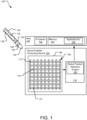
- FIG. 1 illustrates an example system 100 including a stylus 102 and a stylus-enabled computing device 104.
- the stylus-enabled computing device 104 includes a display 106 that is integrated with a digitizer sensor 108 including column conductive strips 112 and row conductive strips 110.
- the row conductive strips 110 and column conductive strips 112 are electrically coupled to a circuit 114 and operative to detect an electromagnetic signal emitted by the stylus 102. In some implementations, the conductive strips are further operative to detect an input from a human finger, hand, or other objects.
- the row conductive strips 110 and column conductive strips 112 may each be electrically insulated from one another to form a grid-based capacitive sensor.
- the row conductive strips 110 and column conductive strips 112 are, in one implementation, arranged to enhance capacitive coupling between the row conductive strips 110 and the column conductive strips 112, such as around junctions 116 formed between row conductive strips 110 and column conductive strips 112.
- the capacitive coupling is, for example, sensitive to the presence of conductive objects, such as fingertips.
- the digitizer sensor 108 is formed with a matrix of electrode junctions 116 that are not constructed based on rows and columns of conductive strips.
- the circuit 114 manages and controls stylus-based detection and, in applicable implementations, finger based detection. Together, the digitizer sensor 108 and the circuit 114 form a digitizer system. During stylus-based detection, output from both the row conductive strips 110 and the column conductive strips 112 are sampled to detect a signal transmitted by the stylus 102 and to determine the coordinates of a writing tip 118 of the stylus 102 relative to the digitizer sensor 108.
- the circuit 114 includes a stylus position detection engine 120 that performs actions such as processing signals received by the stylus 102 and determining the coordinates of the writing tip 118.
- the stylus 102 is also referred to herein as an "active stylus” because it includes electrical components, such as an integrated circuit (IC) 122 that controls generation of a signal transmitted by the stylus 102.
- the IC 122 may encode information generated, stored, or sensed by the stylus 102 on the signal transmitted by the stylus 102.
- the IC 122 may, for example, include one or more application-specific integrated circuits ("ASICs"), one or more system on chips (“SOCs”), and/or one or more programmable intelligent computers (“PICs”), etc.
- ASICs application-specific integrated circuits
- SOCs system on chips
- PICs programmable intelligent computers
- the signal generated by the IC 122 is transmitted by one or more electrodes (e.g., an electrode 124) electrically coupled to the IC 122 and separated from the writing tip 118 along a primary (e.g., longitudinal) axis of the stylus 102.
- the electrode may form part of an exterior surface of the stylus 102 that is electrically separated from the writing tip 118.
- the electrode 124 is a signal-emitting electrode that transmits a position signal to the digitizer sensor 108.
- the position signal can be used to identify a position of the writing tip 118 at a given point in time, even if there is no conductive material within the writing tip 118.
- the electrode 124 may take on a variety of forms in different implementations.
- the electrode 124 is a conductive, annular-shaped component that forms a ring about an outer perimeter of the stylus 102.
- the electrode 124 is a conductive, annular-shaped component positioned inside an external housing of the stylus 102.
- the stylus 102 operates by periodically transmitting a beacon signal that may be detected by the digitizer sensor 108. Synchronization between the stylus 120 and the circuit 114 (e.g., the stylus position detection engine 120) provides for matching sampling periods of the circuit 114 to transmission periods of the stylus 102.
- the stylus 102 may include one or more sensor(s) 126 for collecting and identifying various position and orientation information such as applied pressure, tilt, rotation, etc.
- the stylus 102 may be pressure sensitive and include a pressure sensor among sensor(s) 126 for sensing pressure applied on the writing tip 118.
- the stylus 102 includes a tilt sensor among sensor(s) 126 for detecting a tilt of the stylus relative to the plane of the digitizer sensor 108.
- Information collected by the sensor(s) 126 can be transmitted to the stylus-enabled computing device 104 in various ways.
- the IC 122 encodes information sensed by the sensor(s) 126 (e.g., pressure, tilt, etc.) onto the beacon signal.
- the stylus 102 transmits information sensed by the sensor(s) 126 transmitted on a separate burst signal.
- the stylus 102 may also periodically transmit other information related to the stylus 102, related to the environment around the stylus 102, to a user using the stylus 102, capabilities of the stylus 102, or information received from a third party device.
- Additional information related to the stylus may, for example, include indications of a pressed button(s) (e.g., a button 130), identification, manufacturer, version, media access control (MAC) address, and stored configurations such as color, tip type, brush, and-ons.
- a pressed button(s) e.g., a button 130
- identification e.g., a button 130
- manufacturer e.g., a button 130
- MAC media access control
- the stylus position detection engine 120 decodes information received from the stylus 102 to determine a current position of the writing tip 118 relative to X and Y coordinates of the digitizer sensor 108.
- other handheld devices are configured to interact with the digitizer sensor 108 and may be operated in a manner similar to the stylus 102 and tracked by the stylus position detection engine 120.
- Output from the circuit 114 is reported to a host 128, as shown.
- This output may include various information such as coordinates of the writing tip 118 of the stylus 102, orientation (e.g., pen-up or pen-down status) of the writing tip 118, pressure applied on the writing tip 118, and additional information provided by the stylus 102 (e.g., pressure, tilt, battery level, etc.)
- the circuit 114 may include one or more additional engines (not shown) for decoding and processing other types of information detected by the digitizer sensor 108, such as for decoding and processing 'touch' information detected when a user places a finger, hand, or other objects in near vicinity of the digitizer sensor 108.
- the circuit 114 uses both analog and digital processing to process signals detected with the digitizer sensor 108.
- some and/or all of the functionalities of the stylus position detection engine 120 are performed by the host 128.
- the host 128 and/or stylus position detection engine 120 may transmit the information received from the digitizer sensor 108 to an application manager or a relevant application (e.g., application 136), such as an application stored in memory 134 of the host 128 and executable by a processor 132 of the host 128.
- the stylus 102 additionally includes a wireless communication unit 138, such as an auxiliary channel with Bluetooth communication, near field communication (NFC), radio frequency (RF) communication that communicates with the application(s) 136 of the host 128 for passing information between the stylus 102 and the host 128.
- a wireless communication unit 138 such as an auxiliary channel with Bluetooth communication, near field communication (NFC), radio frequency (RF) communication that communicates with the application(s) 136 of the host 128 for passing information between the stylus 102 and the host 128.
- the stylus 102 does not include signal-emitting components in the writing tip 118.
- the writing tip 118 may be made of one or more dielectrics, such as plastic, rubber, ceramics, etc.
- the stylus position detection engine 120 determines the position of the writing tip 118 using a relative angle detection element also included in the stylus.
- the term "relative angle detection element" refers to an element of the stylus 102 that provides the digitizer sensor 108 with information for determining an angle of the handheld device relative to the digitizer sensor.
- the relative angle detection element is a tilt sensor.
- the stylus position detection engine 120 uses information from the tilt sensor and a detected position of the electrode 124 to calculate the position of the writing tip 118.
- the relative angle detection element is a second signal-emitting electrode (as shown and discussed below with respect to FIG. 3 ).
- the stylus position detection engine 120 determines the position of the writing tip 118 based on detectable positions of two electrodes of the stylus 102 (e.g., the signal emitting electrode 124 and another electrode (not shown)) and a known separation between the two electrodes along a longitudinal axis of the stylus 102 (e.g., using similar triangles based on orientation relative to the digitizer sensor 108 to solve for a position of the writing tip 118).
- two electrodes of the stylus 102 e.g., the signal emitting electrode 124 and another electrode (not shown)
- a known separation between the two electrodes along a longitudinal axis of the stylus 102 e.g., using similar triangles based on orientation relative to the digitizer
- FIG. 2 illustrates an example system 200 which does not form part of the claimed invention, the example system 200 including a stylus 202 for use with a stylus-enabled computing device including a digitizer sensor 210.
- the stylus 202 includes a housing 212 formed around a number of electrical components including, for example, an integrated circuit (IC) 204 that generates a position signal for transmission from a signal-emitting electrode 206 of the stylus 202 to the digitizer sensor 210.
- the signal is, for example, usable by the digitizer sensor 210 to compute a current position of the writing tip 218.
- IC integrated circuit
- the signal-emitting electrode 206 is not positioned at or within the writing tip 218 of the stylus 202. Rather, the signal-emitting electrode 206 is electrically coupled to the IC 204 and separated from a writing tip 218 of the stylus along a primary (e.g., longitudinal) axis 214 of the stylus 202. In some implementations, the writing tip 218 is not electrically coupled to the IC 204 and is not configured for transmission of the position signal.
- the writing tip 218 may be constructed fully or partially from one or more dielectric materials, such as a plastic, rubber, porcelain, glass, etc. In one implementation, the writing tip 218 is constructed entirely of dielectric material.
- the signal-emitting electrode 206 is, in FIG. 2 , shown to be annular in shape and formed about a circumference of the stylus 202 so as to form a portion of an exterior surface of the housing 212.
- the signal-emitting electrode 206 is a conductive ring encircling the housing 212 or formed integrally with the housing 212 of the stylus 202.
- a number of electrode dimensions may be suitable; however, one suitable example signal-emitting electrode 206 is a few millimeters in diameter and very thin.
- Position detection may be more accurate if the signal-emitting electrode is placed in a region the user is unlikely to touch when utilizing the stylus 202.
- the signal-emitting electrode 206 is annular in shape, the emitted signals are not affected by rotation of the stylus 202 relative to the digitizer sensor 210, which simplifies tip position calculation.
- the system 200 implements mechanisms to correct for observed signal variances due to rotation of the stylus 202.
- the signal-emitting electrode 206 is formed below the housing 212 of the stylus 202 instead of exterior to the housing 212, as shown.
- the stylus 202 further includes a tilt sensor 208 for detecting a tilt of the stylus 202 relative to a plane, such as an x-y coordinate plane of the digitizer sensor 210 and/or a ground plane of the earth.
- the tilt sensor 208 is one example of a relative angle detection element and may take on any one of a number of suitable forms including without limitation that of a tilt switch, rolling ball sensor, mercury switch, accelerometer, etc.
- information collected by the tilt sensor 208 is transmitted to the stylus-enabled computing device in various ways.
- the IC 204 encodes information sensed by the tilt sensor 208 onto a signal transmitted by the signal-emitting electrode 206 and received by the digitizer sensor 210.
- the stylus 202 transmits tilt information sensed by the tilt sensor 208 on a separate burst signal.
- the information from the tilt sensor 208 may be transmitted back to the stylus-enabled computing device using a wireless communication unit (not shown) further included within the housing 212.
- a stylus position detection engine (not shown) of the stylus-enabled computing device determines a position of the writing tip 218 by detecting a position of the signal-emitting electrode 206 and uses this position in conjunction with data from the tilt sensor 208 to calculate the coordinates of the writing tip 218 on the digitizer sensor 210.
- a relative position of the signal-emitting electrode 206 may be determined by analyzing a strength and detected location of an electrical coupling between the signal-emitting electrode 206 and one or more electrodes of the digitizer sensor 210.
- data from the tilt sensor 208 may be usable to identify an angle ( ⁇ ) of the stylus relative to the digitizer sensor 210.
- equation (1) (above) for extracting the writing tip 218 facilitates greater flexibility in design for the writing tip 218.
- the writing tip 218 may assume a number of different shapes and sizes and/or be interchangeably replaced by a user without disrupting (e.g., repositioning or altering) the electrical components used to generate and transmit the position signal, such as the IC 204, the electrode 206, or the connections between the two.
- the IC 204 further includes a mechanism for sensing a type of writing tip currently attached to the stylus 202.
- the IC 204 may be configured to recognize which of a number of different, interchangeable writing tips is currently-attached to the stylus 202 and to send an identifier to the stylus position detection engine of the stylus-enabled computing device.
- the stylus position detection engine may, for example use the received identifier to look up or otherwise compute dimensions of the writing tip 218 and use this information in computing the position of the writing tip 218.
- FIG. 3 illustrates another example system 300 including a stylus 302 for use with a digitizer sensor 310 of a stylus-enabled computing device 310.
- the stylus 302 includes a housing 312 and two electrodes (e.g., a first electrode 306 and a second electrode 308).
- the first electrode 306 and/or second electrode 308 may assume different shapes, sizes, and positions.
- both the first electrode 306 and the second electrode 308 are conductive, annular-shaped components encircling the longitudinal axis 314 of the stylus 302 and forming a part of the outer-surface of the housing 312.
- the first electrode 306 and/or the second electrode 308 may be non-annular in shape and/or formed below the outer surface of the housing 312, such as when the outer surface of the housing 312 is non-conductive and therefore unlikely to interfere with the electrode signals.
- An integrated circuit (IC) 304 is positioned within the housing 314 and operable to generate signals for transmission via the first electrode 306 and the second electrode 308 to the digitizer sensor 310.
- the signals transmitted from the first electrode 306 and the second electrode 308 are independently detectable by the digitizer sensor 310.
- the two transmitted signals cause electrostatic coupling at two discrete and detectable locations of the digitizer sensor 310.
- the two transmitted signals are of and independently detectable frequencies and/or include different encoded information. Signals transmitted by the electrodes 306 and 308 are therefore useable to positively determine the positions of each one of the electrodes 306 and 308 relative to the coordinate system of the digitizer sensor 310.
- the electrodes 306 and 308 are separated from one another and also separated from a writing tip 318 of the stylus 302 along the longitudinal axis 314 of the stylus 302.
- the writing tip 318 is not electrically coupled to the IC 304 and is not configured for signal transmission.
- the writing tip 318 may be constructed fully or partially from one or more dielectric materials, such as a plastic, rubber, porcelain, glass, etc. In one implementation, the writing tip 318 is constructed entirely of dielectric material.
- a position of the writing tip 318 can be extracted without using tilt sensor or other sensor information.
- the position of the writing tip 318 can therefore be determined by solving equation (2) (above) for x tip . Since the position of the writing tip 318 and/or the relative angle ( ⁇ ) between the stylus 302 and the digitizer sensor 310 can be determined from equation (2), above, the second electrode 308 is, like the tilt sensor of FIG. 2 , also referred to herein as a relative angle detection element.
- the position of the writing tip 318 can be calculated without using additional sensor positioning or orientation information.
- the position of the writing tip 318 can be determined without use of a tilt sensor or any other supplemental sensors that may be included within the housing 314.
- the implementation of FIG. 3 provides design flexibility for the construction of the writing tip 318.
- the writing tip 318 may assume a number of different shapes and sizes and/or be interchangeably replaced by a user without disrupting (e.g., repositioning or altering) the electrical components used to generate and transmit position signal information.
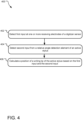
- FIG. 4 illustrates example operations 400 for position tracking of an active stylus that does not include a signal-emitting electrode within a writing tip.
- a first detection operation 402 detects a first input at one or more electrodes of a digitizer sensor.
- the digitizer sensor may be embedded beneath the exterior surface of a display, such as a display included in a tablet, mobile phone, or other display device.
- the detected first input is, in one implementation, in the form of a signal emitted by a first signal-emitting electrode within the active stylus and separated from a writing tip along a longitudinal axis of the active stylus.
- a second detecting operation 404 detects a second input from a relative angle detection element of the active stylus.
- the second input provides information usable to determine an angle of the active stylus relative to the digitizer sensor.
- the second input may include tilt sensor information collected by a tilt sensor of the active stylus.
- the tilt sensor information and a position of the one or more receiving electrodes can, together, be used to calculate a position of the writing tip.
- the second input is a signal transmitted by a second signal-emitting electrode of the active stylus that is detected by other receiving electrodes at the digitizer sensor.
- the second signal-emitting electrode is separated from the first signal-emitting electrode and the writing tip of the active stylus along a longitudinal axis of the stylus and signals transmitted by the first and second signal-emitting electrodes provide relative position information usable for calculating a position of the writing tip.
- a calculating operation 406 calculates the position of the writing tip of the active stylus based on the positions of the receiving electrodes that receive the first input and the second input from the relative angle detection element.
- the extraction operation 406 extracts the position of the writing tip using information from a tilt sensor in conjunction with position information for the first signal-emitting electrode relative to the digitizer sensor (e.g., as described with respect to FIG. 2 ).
- the calculation operation 406 calculates the position of the writing tip without using a tilt sensor, such as by using a known separation between two signal-emitting electrodes and the positions of multiple receiving electrodes of the digitizer sensor that electrically couple with the two signal-emitting electrodes (e.g., as described with respect to FIG. 3 ).
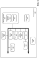
- FIG. 5 illustrates an example schematic of a processing device 500 suitable for determining coordinates of a writing tip of a handheld device accessory, such as an active stylus, according to the herein described technology.
- the example computing device 500 includes one or more processor units 502, one or more memory devices 504, a display 506, and other interfaces 508 (e.g., buttons).
- the memory 504 generally includes both volatile memory (e.g., RAM) and non-volatile memory (e.g., flash memory).
- An operating system 510 such as the Microsoft Windows ® operating system, the Microsoft Windows ® Phone operating system or a specific operating system designed for a gaming device, resides in the memory 504 and is executed by the processor unit(s) 502, although it should be understood that other operating systems may be employed.
- One or more applications 512 such as a stylus position detection engine are loaded in the memory device 504 and executed on the operating system 510 by the processor(s) 502.
- the applications 512 may receive input from the display 506 and/or a digitizer sensor 535 embedded within or beneath the display 512.
- the example computing device 500 includes a power supply 516, which is powered by one or more batteries or other power sources and which provides power to other components of the processing device 500.
- the power supply 516 may also be connected to an external power source that overrides or recharges the built-in batteries or other power sources.
- the processing device 500 includes one or more communication transceivers 530 and an antenna 532 to provide network connectivity (e.g., a mobile phone network, Wi-Fi ® , BlueTooth ® , etc.).
- the computing device 500 may also include various other components, such as a positioning system (e.g., a global positioning satellite transceiver), one or more accelerometers, one or more cameras, an audio interface (e.g., a microphone 534, an audio amplifier and speaker and/or audio jack), and additional storage 528. Other configurations may also be employed.
- a mobile operating system various applications (including a stylus position detection engine) and other modules and services may be embodied by instructions stored in memory 504 and/or storage devices 528 and processed by the processing unit(s) 502.
- the memory 504 may be memory of host device or of an accessory that couples to a host.
- Some or all aspects of the stylus position detection engine described with respect to FIGs. 1-4 , above, may be saved in memory of one or more of a host device, display accessory (e.g., touchscreen accessory including a digitizer sensor), or a handheld writing accessory (e.g., the active stylus).
- some or all aspects of the stylus position detection engine may be executable by any one or more of a host device, display accessory, or a handheld writing accessory (e.g., the active stylus interacting with the display accessory).
- the computing device 500 may include a variety of tangible computer-readable storage media and intangible computer-readable communication signals.
- Tangible computer-readable storage can be embodied by any available media that can be accessed by the speech recognition device 500 and includes both volatile and nonvolatile storage media, removable and non-removable storage media.
- Tangible computer-readable storage media excludes intangible and transitory communications signals and includes volatile and nonvolatile, removable and non-removable storage media implemented in any method or technology for storage of information such as computer readable instructions, data structures, program modules or other data.
- Tangible computer-readable storage media includes, but is not limited to, RAM, ROM, EEPROM, flash memory or other memory technology, CDROM, digital versatile disks (DVD) or other optical disk storage, magnetic cassettes, magnetic tape, magnetic disk storage or other magnetic storage devices, or any other tangible medium which can be used to store the desired information and which can be accessed by the speech recognition device 500.
- intangible computer-readable communication signals may embody computer readable instructions, data structures, program modules or other data resident in a modulated data signal, such as a carrier wave or other signal transport mechanism.
- modulated data signal means a signal that has one or more of its characteristics set or changed in such a manner as to encode information in the signal.
- intangible communication signals include wired media such as a wired network or direct-wired connection, and wireless media such as acoustic, RF, infrared and other wireless media.
- An article of manufacture may comprise a tangible storage medium to store logic.
- Examples of a storage medium may include one or more types of computer-readable storage media capable of storing electronic data, including volatile memory or non-volatile memory, removable or non-removable memory, erasable or non-erasable memory, writeable or re-writeable memory, and so forth.
- Examples of the logic may include various software elements, such as software components, programs, applications, computer programs, application programs, system programs, machine programs, operating system software, middleware, firmware, software modules, routines, subroutines, functions, methods, procedures, software interfaces, application program interfaces (API), instruction sets, computing code, computer code, code segments, computer code segments, words, values, symbols, or any combination thereof.
- API application program interfaces
- an article of manufacture may store executable computer program instructions that, when executed by a computer, cause the computer to perform methods and/or operations in accordance with the described embodiments.
- the executable computer program instructions may include any suitable type of code, such as source code, compiled code, interpreted code, executable code, static code, dynamic code, and the like.
- the executable computer program instructions may be implemented according to a predefined computer language, manner or syntax, for instructing a computer to perform a certain function.
- the instructions may be implemented using any suitable high-level, low-level, object-oriented, visual, compiled and/or interpreted programming language.
Landscapes
- Engineering & Computer Science (AREA)
- General Engineering & Computer Science (AREA)
- Theoretical Computer Science (AREA)
- Human Computer Interaction (AREA)
- Physics & Mathematics (AREA)
- General Physics & Mathematics (AREA)
- Position Input By Displaying (AREA)
Claims (8)
- Aktiver Stift (102) zur Verwendung mit einem Digitalisiersensor (108) einer stiftfähigen Rechenvorrichtung (104), wobei der aktive Stift (102) umfasst:eine Schreibspitze (118);einen integrierten Schaltkreis (122), der so konfiguriert ist, dass er ein erstes Signal erzeugt;eine erste Elektrode (124), die von der Schreibspitze (118) entlang einer Längsachse des aktiven Stiftes (102) getrennt ist, wobei die erste Elektrode (124) elektrisch mit dem integrierten Schaltkreis (122) gekoppelt ist und so konfiguriert ist, dass sie das erste Signal an den Digitalisiersensor (108) zum Erfassen durch den Digitalisiersensor überträgt; dadurch gekennzeichnet, dass der aktive Stift umfasst:eine zweite Elektrode (124), die mit dem integrierten Schaltkreis (122) gekoppelt ist und von der ersten Elektrode (124) und der Schreibspitze (118) durch einen Abstand entlang der Längsachse des aktiven Stiftes (102) getrennt ist, wobei die zweite Elektrode so konfiguriert ist, dass sie ein zweites Signal, das von dem integrierten Schaltkreis erzeugt wird, an den Digitalisiersensor (108) zum Erfassen durch den Digitalisiersensor überträgt;wobei das erste Signal und das zweite Signal von der stiftfähigen Rechenvorrichtung (104) zum Berechnen (406) einer Position der Schreibspitze (118) relativ zu einem X- und Y-Koordinatensystem des Digitalisiersensors (108) verwendet werden können.
- Aktiver Stift (102) nach Anspruch 1, wobei die Schreibspitze (118) vollständig aus dielektrischem Material hergestellt ist.
- Aktiver Stift (102) nach Anspruch 1, wobei die erste Elektrode (124) ein leitender Ring ist, der die Längsachse umgibt und auf einer äußeren Oberfläche des aktiven Stiftes (102) freiliegt.
- Aktiver Stift (102) nach Anspruch 1, wobei die erste Elektrode (124) und die zweite Elektrode (124) beide auf einer äußeren Oberfläche des aktiven Stifts (102) freiliegen.
- Aktiver Stift (102) nach Anspruch 1, wobei das erste Signal und das zweite Signal unabhängig voneinander von dem Digitalisiersensor detektierbar sind; und
wobei das erste und das zweite Signal eine elektrostatische Kopplung an zwei diskreten und detektierbaren Positionen des Digitalisiersensors (108) verursachen. - Aktiver Stift (102) nach Anspruch 1, wobei das erste Signal und das zweite Signal unabhängig voneinander detektierbare Frequenzen aufweisen und/oder unterschiedliche codierte Informationen beinhalten.
- Verfahren (400), umfassend:Verwenden einer ersten signalemittierenden Elektrode (306) eines aktiven Stifts (102), die von einer Schreibspitze (118) des aktiven Stifts (102) durch einen Abstand entlang einer Längsachse des aktiven Stifts (102) getrennt ist, um ein erstes Signal zu übertragen;Verwenden einer zweiten signalemittierenden Elektrode (308) des aktiven Stifts (102), die von der ersten signalemittierenden Elektrode und ebenfalls von der Schreibspitze entlang der Längsachse des aktiven Stifts (102) getrennt ist, um ein zweites Signal zu übertragen, wobei das erste Signal und das zweite Signal unabhängig voneinander durch den Digitalisiersensor detektierbar sind;wobei das erste und das zweite Signal eine elektrostatische Kopplung an zwei diskreten und detektierbaren Positionen des Digitalisiersensors (108) verursachen;unter Verwendung einer Rechenvorrichtung (104), die einen Digitalisiersensor (108) aufweist, der in einem elektronischen Bildschirm (506) beinhaltet ist, Detektieren (404) des ersten Signals als eine erste Eingabe an Empfangselektroden (124) des Digitalisiersensors (108);unter Verwendung des Digitalisiersensors (108) Detektieren (404) des zweiten Signals als zweite Eingabe an den Empfangselektroden des Digitalisiersensors (108);Verwenden der ersten Eingabe, um eine Position x1 der ersten signalemittierenden Elektrode (124) zu bestimmen, die auf ein X- und Y-Koordinatensystem des Digitalisiersensors (108) projiziert wird;Verwenden der zweiten Eingabe, um eine Position x2 der zweiten signalemittierenden Elektrode (308) zu bestimmen, die auf ein X- und Y-Koordinatensystem des Digitalisiersensors (108) projiziert wird;unter Verwendung der Rechenvorrichtung (104) Berechnen (406) einer Position der Schreibspitze (118) xtip des aktiven Stifts (102) relativ zu dem X- und Y-Koordinatensystem des Digitalisiersensors (108) durch Lösen einer Gleichung, wobei die Differenz zwischen x2 und x1, dividiert durch A1, gleich der Differenz zwischen x2 und xtip, dividiert durch A2, ist, wobei A1 ein Abstand zwischen der ersten und der zweiten Elektrode entlang der Längsachse des aktiven Stifts ist und A2 der Abstand zwischen der zweiten Elektrode und der Schreibspitze (118) des aktiven Stifts ist, wobei A1 und A2 Hypotenusen ähnlicher Dreiecke darstellen.
- System (200), umfassend:den aktiven Stift (102) der Ansprüche 1-4; undeine stiftfähige Rechenvorrichtung (104); wobei die stiftfähige Rechenvorrichtung (104) umfasst:mindestens eine Speichervorrichtung (504);mindestens eine Verarbeitungsvorrichtung (500);einen Digitalisiersensor (108), der in einem elektronischen Bildschirm (506) beinhaltet ist;eine Stiftpositionsdetektions-Engine, die in dem Speicher (504) gespeichert ist und von dem Prozessor (500) ausgeführt werden kann zum:Detektieren einer ersten Eingabe von dem Digitalisiersensor (108), die eine Position einer oder mehrerer signalempfangender Elektroden des Digitalisiersensors (108) anzeigt, die elektrisch mit dem ersten Signal koppelt, das von der ersten signalemittierenden Elektrode (124) des aktiven Stifts (102) übertragen wird;Detektieren einer zweiten Eingabe von dem Digitalisiersensor (108), die eine Position einer oder mehrerer signalempfangender Elektroden des Digitalisiersensors (108) anzeigt, die elektrisch mit dem zweiten Signal koppelt, das von der zweiten signalemittierenden Elektrode (308) des aktiven Stifts (102) übertragen wird, wobei das erste Signal und das zweite Signal unabhängig voneinander von dem Digitalisiersensor (108) detektierbar sind;Verwenden der ersten Eingabe von dem Digitalisiersensor (108), um eine Position x1 der ersten signalemittierenden Elektrode (124) zu bestimmen, die auf ein X- und Y-Koordinatensystem des Digitalisiersensors (108) projiziert wird;Verwenden der zweiten Eingabe von dem Digitalisiersensor (108), um eine Position x2 der zweiten signalemittierenden Elektrode (308) zu bestimmen, die auf das X- und Y-Koordinatensystem des Digitalisiersensors (108) projiziert wird;Berechnen einer Position der Schreibspitze (118) xtip des aktiven Stifts (102) relativ zu dem X- und Y-Koordinatensystem des Digitalisiersensors (108) durch Lösen einer Gleichung, wobei die Differenz zwischen x2 und x1, dividiert durch A1, gleich der Differenz zwischen x2 und xtip, dividiert durch A2, ist, wobei A1 ein Abstand zwischen der ersten und der zweiten Elektrode entlang der Längsachse des aktiven Stifts ist und A2 der Abstand zwischen der zweiten Elektrode und der Schreibspitze (118) des aktiven Stifts ist, wobei A1 und A2 Hypotenusen ähnlicher Dreiecke darstellen.
Applications Claiming Priority (2)
| Application Number | Priority Date | Filing Date | Title |
|---|---|---|---|
| US15/343,681 US10310636B2 (en) | 2016-11-04 | 2016-11-04 | Active stylus |
| PCT/US2017/058923 WO2018085164A1 (en) | 2016-11-04 | 2017-10-30 | Active stylus |
Publications (2)
| Publication Number | Publication Date |
|---|---|
| EP3535647A1 EP3535647A1 (de) | 2019-09-11 |
| EP3535647B1 true EP3535647B1 (de) | 2024-06-26 |
Family
ID=60473592
Family Applications (1)
| Application Number | Title | Priority Date | Filing Date |
|---|---|---|---|
| EP17804686.8A Active EP3535647B1 (de) | 2016-11-04 | 2017-10-30 | Aktiver stift |
Country Status (4)
| Country | Link |
|---|---|
| US (1) | US10310636B2 (de) |
| EP (1) | EP3535647B1 (de) |
| CN (1) | CN109923502B (de) |
| WO (1) | WO2018085164A1 (de) |
Families Citing this family (12)
| Publication number | Priority date | Publication date | Assignee | Title |
|---|---|---|---|---|
| US10254862B2 (en) * | 2016-07-19 | 2019-04-09 | Asustek Computer Inc. | Stylus and touch control method |
| WO2018136057A1 (en) * | 2017-01-19 | 2018-07-26 | Hewlett-Packard Development Company, L.P. | Input pen gesture-based display control |
| TWM570464U (zh) * | 2018-08-22 | 2018-11-21 | 宏碁股份有限公司 | 電容式觸控筆 |
| WO2020202352A1 (ja) | 2019-03-29 | 2020-10-08 | 株式会社ワコム | ペン状態検出回路及びペン状態検出方法 |
| TWI687861B (zh) * | 2019-05-08 | 2020-03-11 | 友達光電股份有限公司 | 主動筆及使用主動筆的觸控顯示系統 |
| CN110347272B (zh) * | 2019-07-11 | 2025-07-18 | 汉王科技股份有限公司 | 电容笔及其制造方法 |
| CN112346582B (zh) * | 2019-08-08 | 2022-07-22 | 华为技术有限公司 | 一种触控笔以及电子设备 |
| EP3789855A1 (de) * | 2019-09-05 | 2021-03-10 | Microsoft Technology Licensing, LLC | Taststiftspitzenentwurf und genauigkeitsverbesserung |
| CN111990983B (zh) * | 2020-08-31 | 2023-08-22 | 深圳平安智慧医健科技有限公司 | 心率监测方法、智能笔、终端及存储介质 |
| CN112148139B (zh) * | 2020-09-28 | 2022-07-26 | 联想(北京)有限公司 | 一种姿态识别方法和计算机可读存储介质 |
| CN112416175B (zh) * | 2020-11-30 | 2024-05-14 | Oppo广东移动通信有限公司 | 磨损监控方法、电子设备、触控书写设备及触控系统 |
| CN113178900B (zh) * | 2021-03-15 | 2023-02-17 | 荣耀终端有限公司 | 无线充电系统、芯片和无线充电电路 |
Family Cites Families (26)
| Publication number | Priority date | Publication date | Assignee | Title |
|---|---|---|---|---|
| IL141400A0 (en) | 1998-08-18 | 2002-03-10 | Digital Ink Inc | Handwriting device with detection sensors for absolute and relative positioning |
| JP2005534230A (ja) | 2002-07-22 | 2005-11-10 | メジャメント スペシャリティーズ インク | 音響信号の軸方向伝送用の超音波トランスデューサを有するハンドヘルド型機器 |
| EP1735770A4 (de) | 2004-02-27 | 2012-04-25 | N trig ltd | Rauschminderung in einem digitalisierersystem |
| DE102004045871B4 (de) * | 2004-09-20 | 2006-11-23 | Novaled Gmbh | Verfahren und Schaltungsanordnung zur Alterungskompensation von organischen Lichtemitterdioden |
| JP5324440B2 (ja) | 2006-07-12 | 2013-10-23 | エヌ−トリグ リミテッド | デジタイザのためのホバリングおよびタッチ検出 |
| GB2466566B (en) | 2008-12-22 | 2010-12-22 | N trig ltd | Digitizer, stylus and method of synchronization therewith |
| US9122322B2 (en) | 2011-03-17 | 2015-09-01 | Microsoft Technology Licensing, Llc | Interacting tips for a digitizer stylus |
| US8638320B2 (en) | 2011-06-22 | 2014-01-28 | Apple Inc. | Stylus orientation detection |
| US10082889B2 (en) | 2011-10-28 | 2018-09-25 | Atmel Corporation | Multi-electrode active stylus tip |
| US20140028635A1 (en) | 2012-07-27 | 2014-01-30 | Christoph Horst Krah | Modular stylus device |
| US10642376B2 (en) | 2012-11-28 | 2020-05-05 | Intel Corporation | Multi-function stylus with sensor controller |
| US8978487B2 (en) | 2012-12-13 | 2015-03-17 | Blackberry Limited | Capacitive force sensor with magnetic spring |
| WO2014127383A2 (en) | 2013-02-17 | 2014-08-21 | Zeliff Zachary Joseph | Stylus for capacitive touchscreen |
| WO2014130355A2 (en) | 2013-02-19 | 2014-08-28 | Jcm Electronic Stylus Llc | Electronic stylus with low skew tip for capacitive touch screens |
| US10275049B2 (en) | 2013-04-10 | 2019-04-30 | Nvidia Corporation | Stylus signaling for capacitive touch screen panels |
| US9513721B2 (en) | 2013-09-12 | 2016-12-06 | Microsoft Technology Licensing, Llc | Pressure sensitive stylus for a digitizer |
| US9477330B2 (en) * | 2013-11-05 | 2016-10-25 | Microsoft Technology Licensing, Llc | Stylus tilt tracking with a digitizer |
| US9298285B2 (en) | 2013-12-05 | 2016-03-29 | Wacom Co., Ltd. | Stylus tip shape |
| JP5761773B1 (ja) | 2013-12-25 | 2015-08-12 | 株式会社ワコム | 位置指示用モジュールおよびスタイラスペン |
| JP6304814B2 (ja) * | 2014-05-23 | 2018-04-04 | 株式会社ワコム | 位置検出装置及び位置指示器 |
| KR20170019473A (ko) | 2014-07-02 | 2017-02-21 | 쓰리엠 이노베이티브 프로퍼티즈 컴파니 | 의도하지 않은 터치 신호의 배제를 포함하는 터치 시스템 및 방법 |
| US9874951B2 (en) | 2014-11-03 | 2018-01-23 | Microsoft Technology Licensing, Llc | Stylus for operating a digitizer system |
| KR102307692B1 (ko) * | 2014-11-28 | 2021-10-05 | 삼성전자 주식회사 | 펜 입력장치, 그 입력 좌표 보정방법 및 이를 제공하는 전자장치 |
| KR102384766B1 (ko) | 2014-12-07 | 2022-04-07 | 마이크로소프트 테크놀로지 라이센싱, 엘엘씨 | 디지타이저 시스템을 작동시키기 위한 스타일러스 |
| US9575573B2 (en) * | 2014-12-18 | 2017-02-21 | Apple Inc. | Stylus with touch sensor |
| US10095361B2 (en) | 2015-03-18 | 2018-10-09 | Microsoft Technology Licensing, Llc | Stylus detection with capacitive based digitizer sensor |
-
2016
- 2016-11-04 US US15/343,681 patent/US10310636B2/en active Active
-
2017
- 2017-10-30 WO PCT/US2017/058923 patent/WO2018085164A1/en not_active Ceased
- 2017-10-30 CN CN201780068401.2A patent/CN109923502B/zh active Active
- 2017-10-30 EP EP17804686.8A patent/EP3535647B1/de active Active
Also Published As
| Publication number | Publication date |
|---|---|
| US20180129310A1 (en) | 2018-05-10 |
| CN109923502A (zh) | 2019-06-21 |
| WO2018085164A1 (en) | 2018-05-11 |
| US10310636B2 (en) | 2019-06-04 |
| CN109923502B (zh) | 2022-08-12 |
| EP3535647A1 (de) | 2019-09-11 |
Similar Documents
| Publication | Publication Date | Title |
|---|---|---|
| EP3535647B1 (de) | Aktiver stift | |
| EP3427133B1 (de) | Stift in der feldstärkenmessungskalibrierung | |
| US10185415B2 (en) | Configurable communication protocol for communication between a stylus device and a host device | |
| CN113311951B (zh) | 位置指示器以及位置检测装置 | |
| JP6832372B2 (ja) | スタイラスのソフトタッチ検出 | |
| KR102301621B1 (ko) | 스타일러스 펜, 터치 패널 및 이들을 구비한 좌표 측정 시스템 | |
| US10459538B2 (en) | Pressure sensitive stylus | |
| US20160048209A1 (en) | Method and apparatus for controlling vibration | |
| KR102568710B1 (ko) | 전자장치 및 그 동작 방법 | |
| US11650674B2 (en) | Electronic device and method for mapping function to button input | |
| CN116466867B (zh) | 笔迹绘制方法、装置、电子设备和可读存储介质 | |
| US12277313B2 (en) | Handwriting drawing method and apparatus, electronic device, and readable storage medium | |
| US12547258B2 (en) | Function mode switching method, electronic device, and system | |
| US10114496B2 (en) | Apparatus for measuring coordinates and control method thereof | |
| US9823774B2 (en) | Noise reduction in a digitizer system | |
| CN114995665A (zh) | 触控笔的笔尖寿命提示方法、触控笔及电子设备 | |
| CN115543105B (zh) | 一种信息传输方法和装置 | |
| KR20230087961A (ko) | 브러쉬형 액티브 스타일러스 펜과 이를 이용한 입력 시스템 |
Legal Events
| Date | Code | Title | Description |
|---|---|---|---|
| STAA | Information on the status of an ep patent application or granted ep patent |
Free format text: STATUS: UNKNOWN |
|
| STAA | Information on the status of an ep patent application or granted ep patent |
Free format text: STATUS: THE INTERNATIONAL PUBLICATION HAS BEEN MADE |
|
| PUAI | Public reference made under article 153(3) epc to a published international application that has entered the european phase |
Free format text: ORIGINAL CODE: 0009012 |
|
| STAA | Information on the status of an ep patent application or granted ep patent |
Free format text: STATUS: REQUEST FOR EXAMINATION WAS MADE |
|
| 17P | Request for examination filed |
Effective date: 20190416 |
|
| AK | Designated contracting states |
Kind code of ref document: A1 Designated state(s): AL AT BE BG CH CY CZ DE DK EE ES FI FR GB GR HR HU IE IS IT LI LT LU LV MC MK MT NL NO PL PT RO RS SE SI SK SM TR |
|
| AX | Request for extension of the european patent |
Extension state: BA ME |
|
| DAV | Request for validation of the european patent (deleted) | ||
| DAX | Request for extension of the european patent (deleted) | ||
| STAA | Information on the status of an ep patent application or granted ep patent |
Free format text: STATUS: EXAMINATION IS IN PROGRESS |
|
| 17Q | First examination report despatched |
Effective date: 20210317 |
|
| RAP3 | Party data changed (applicant data changed or rights of an application transferred) |
Owner name: MICROSOFT TECHNOLOGY LICENSING, LLC |
|
| RAP3 | Party data changed (applicant data changed or rights of an application transferred) |
Owner name: MICROSOFT TECHNOLOGY LICENSING, LLC |
|
| GRAP | Despatch of communication of intention to grant a patent |
Free format text: ORIGINAL CODE: EPIDOSNIGR1 |
|
| STAA | Information on the status of an ep patent application or granted ep patent |
Free format text: STATUS: GRANT OF PATENT IS INTENDED |
|
| INTG | Intention to grant announced |
Effective date: 20240219 |
|
| P01 | Opt-out of the competence of the unified patent court (upc) registered |
Effective date: 20240313 |
|
| GRAS | Grant fee paid |
Free format text: ORIGINAL CODE: EPIDOSNIGR3 |
|
| GRAA | (expected) grant |
Free format text: ORIGINAL CODE: 0009210 |
|
| STAA | Information on the status of an ep patent application or granted ep patent |
Free format text: STATUS: THE PATENT HAS BEEN GRANTED |
|
| AK | Designated contracting states |
Kind code of ref document: B1 Designated state(s): AL AT BE BG CH CY CZ DE DK EE ES FI FR GB GR HR HU IE IS IT LI LT LU LV MC MK MT NL NO PL PT RO RS SE SI SK SM TR |
|
| REG | Reference to a national code |
Ref country code: GB Ref legal event code: FG4D |
|
| REG | Reference to a national code |
Ref country code: CH Ref legal event code: EP |
|
| REG | Reference to a national code |
Ref country code: DE Ref legal event code: R096 Ref document number: 602017082844 Country of ref document: DE |
|
| PG25 | Lapsed in a contracting state [announced via postgrant information from national office to epo] |
Ref country code: BG Free format text: LAPSE BECAUSE OF FAILURE TO SUBMIT A TRANSLATION OF THE DESCRIPTION OR TO PAY THE FEE WITHIN THE PRESCRIBED TIME-LIMIT Effective date: 20240626 |
|
| PG25 | Lapsed in a contracting state [announced via postgrant information from national office to epo] |
Ref country code: HR Free format text: LAPSE BECAUSE OF FAILURE TO SUBMIT A TRANSLATION OF THE DESCRIPTION OR TO PAY THE FEE WITHIN THE PRESCRIBED TIME-LIMIT Effective date: 20240626 Ref country code: FI Free format text: LAPSE BECAUSE OF FAILURE TO SUBMIT A TRANSLATION OF THE DESCRIPTION OR TO PAY THE FEE WITHIN THE PRESCRIBED TIME-LIMIT Effective date: 20240626 |
|
| REG | Reference to a national code |
Ref country code: LT Ref legal event code: MG9D |
|
| PG25 | Lapsed in a contracting state [announced via postgrant information from national office to epo] |
Ref country code: GR Free format text: LAPSE BECAUSE OF FAILURE TO SUBMIT A TRANSLATION OF THE DESCRIPTION OR TO PAY THE FEE WITHIN THE PRESCRIBED TIME-LIMIT Effective date: 20240927 |
|
| PG25 | Lapsed in a contracting state [announced via postgrant information from national office to epo] |
Ref country code: LV Free format text: LAPSE BECAUSE OF FAILURE TO SUBMIT A TRANSLATION OF THE DESCRIPTION OR TO PAY THE FEE WITHIN THE PRESCRIBED TIME-LIMIT Effective date: 20240626 |
|
| REG | Reference to a national code |
Ref country code: NL Ref legal event code: MP Effective date: 20240626 |
|
| PG25 | Lapsed in a contracting state [announced via postgrant information from national office to epo] |
Ref country code: NO Free format text: LAPSE BECAUSE OF FAILURE TO SUBMIT A TRANSLATION OF THE DESCRIPTION OR TO PAY THE FEE WITHIN THE PRESCRIBED TIME-LIMIT Effective date: 20240926 Ref country code: LV Free format text: LAPSE BECAUSE OF FAILURE TO SUBMIT A TRANSLATION OF THE DESCRIPTION OR TO PAY THE FEE WITHIN THE PRESCRIBED TIME-LIMIT Effective date: 20240626 Ref country code: HR Free format text: LAPSE BECAUSE OF FAILURE TO SUBMIT A TRANSLATION OF THE DESCRIPTION OR TO PAY THE FEE WITHIN THE PRESCRIBED TIME-LIMIT Effective date: 20240626 Ref country code: GR Free format text: LAPSE BECAUSE OF FAILURE TO SUBMIT A TRANSLATION OF THE DESCRIPTION OR TO PAY THE FEE WITHIN THE PRESCRIBED TIME-LIMIT Effective date: 20240927 Ref country code: FI Free format text: LAPSE BECAUSE OF FAILURE TO SUBMIT A TRANSLATION OF THE DESCRIPTION OR TO PAY THE FEE WITHIN THE PRESCRIBED TIME-LIMIT Effective date: 20240626 Ref country code: BG Free format text: LAPSE BECAUSE OF FAILURE TO SUBMIT A TRANSLATION OF THE DESCRIPTION OR TO PAY THE FEE WITHIN THE PRESCRIBED TIME-LIMIT Effective date: 20240626 Ref country code: RS Free format text: LAPSE BECAUSE OF FAILURE TO SUBMIT A TRANSLATION OF THE DESCRIPTION OR TO PAY THE FEE WITHIN THE PRESCRIBED TIME-LIMIT Effective date: 20240926 |
|
| PG25 | Lapsed in a contracting state [announced via postgrant information from national office to epo] |
Ref country code: NL Free format text: LAPSE BECAUSE OF FAILURE TO SUBMIT A TRANSLATION OF THE DESCRIPTION OR TO PAY THE FEE WITHIN THE PRESCRIBED TIME-LIMIT Effective date: 20240626 |
|
| REG | Reference to a national code |
Ref country code: AT Ref legal event code: MK05 Ref document number: 1698248 Country of ref document: AT Kind code of ref document: T Effective date: 20240626 |
|
| PG25 | Lapsed in a contracting state [announced via postgrant information from national office to epo] |
Ref country code: NL Free format text: LAPSE BECAUSE OF FAILURE TO SUBMIT A TRANSLATION OF THE DESCRIPTION OR TO PAY THE FEE WITHIN THE PRESCRIBED TIME-LIMIT Effective date: 20240626 |
|
| PG25 | Lapsed in a contracting state [announced via postgrant information from national office to epo] |
Ref country code: PT Free format text: LAPSE BECAUSE OF FAILURE TO SUBMIT A TRANSLATION OF THE DESCRIPTION OR TO PAY THE FEE WITHIN THE PRESCRIBED TIME-LIMIT Effective date: 20241028 |
|
| PG25 | Lapsed in a contracting state [announced via postgrant information from national office to epo] |
Ref country code: PT Free format text: LAPSE BECAUSE OF FAILURE TO SUBMIT A TRANSLATION OF THE DESCRIPTION OR TO PAY THE FEE WITHIN THE PRESCRIBED TIME-LIMIT Effective date: 20241028 |
|
| PG25 | Lapsed in a contracting state [announced via postgrant information from national office to epo] |
Ref country code: PL Free format text: LAPSE BECAUSE OF FAILURE TO SUBMIT A TRANSLATION OF THE DESCRIPTION OR TO PAY THE FEE WITHIN THE PRESCRIBED TIME-LIMIT Effective date: 20240626 |
|
| PG25 | Lapsed in a contracting state [announced via postgrant information from national office to epo] |
Ref country code: EE Free format text: LAPSE BECAUSE OF FAILURE TO SUBMIT A TRANSLATION OF THE DESCRIPTION OR TO PAY THE FEE WITHIN THE PRESCRIBED TIME-LIMIT Effective date: 20240626 |
|
| PG25 | Lapsed in a contracting state [announced via postgrant information from national office to epo] |
Ref country code: IS Free format text: LAPSE BECAUSE OF FAILURE TO SUBMIT A TRANSLATION OF THE DESCRIPTION OR TO PAY THE FEE WITHIN THE PRESCRIBED TIME-LIMIT Effective date: 20241026 Ref country code: AT Free format text: LAPSE BECAUSE OF FAILURE TO SUBMIT A TRANSLATION OF THE DESCRIPTION OR TO PAY THE FEE WITHIN THE PRESCRIBED TIME-LIMIT Effective date: 20240626 |
|
| PG25 | Lapsed in a contracting state [announced via postgrant information from national office to epo] |
Ref country code: CZ Free format text: LAPSE BECAUSE OF FAILURE TO SUBMIT A TRANSLATION OF THE DESCRIPTION OR TO PAY THE FEE WITHIN THE PRESCRIBED TIME-LIMIT Effective date: 20240626 |
|
| PG25 | Lapsed in a contracting state [announced via postgrant information from national office to epo] |
Ref country code: RO Free format text: LAPSE BECAUSE OF FAILURE TO SUBMIT A TRANSLATION OF THE DESCRIPTION OR TO PAY THE FEE WITHIN THE PRESCRIBED TIME-LIMIT Effective date: 20240626 Ref country code: SK Free format text: LAPSE BECAUSE OF FAILURE TO SUBMIT A TRANSLATION OF THE DESCRIPTION OR TO PAY THE FEE WITHIN THE PRESCRIBED TIME-LIMIT Effective date: 20240626 |
|
| PG25 | Lapsed in a contracting state [announced via postgrant information from national office to epo] |
Ref country code: ES Free format text: LAPSE BECAUSE OF FAILURE TO SUBMIT A TRANSLATION OF THE DESCRIPTION OR TO PAY THE FEE WITHIN THE PRESCRIBED TIME-LIMIT Effective date: 20240626 Ref country code: SM Free format text: LAPSE BECAUSE OF FAILURE TO SUBMIT A TRANSLATION OF THE DESCRIPTION OR TO PAY THE FEE WITHIN THE PRESCRIBED TIME-LIMIT Effective date: 20240626 |
|
| PG25 | Lapsed in a contracting state [announced via postgrant information from national office to epo] |
Ref country code: SM Free format text: LAPSE BECAUSE OF FAILURE TO SUBMIT A TRANSLATION OF THE DESCRIPTION OR TO PAY THE FEE WITHIN THE PRESCRIBED TIME-LIMIT Effective date: 20240626 Ref country code: SK Free format text: LAPSE BECAUSE OF FAILURE TO SUBMIT A TRANSLATION OF THE DESCRIPTION OR TO PAY THE FEE WITHIN THE PRESCRIBED TIME-LIMIT Effective date: 20240626 Ref country code: RO Free format text: LAPSE BECAUSE OF FAILURE TO SUBMIT A TRANSLATION OF THE DESCRIPTION OR TO PAY THE FEE WITHIN THE PRESCRIBED TIME-LIMIT Effective date: 20240626 Ref country code: PL Free format text: LAPSE BECAUSE OF FAILURE TO SUBMIT A TRANSLATION OF THE DESCRIPTION OR TO PAY THE FEE WITHIN THE PRESCRIBED TIME-LIMIT Effective date: 20240626 Ref country code: IS Free format text: LAPSE BECAUSE OF FAILURE TO SUBMIT A TRANSLATION OF THE DESCRIPTION OR TO PAY THE FEE WITHIN THE PRESCRIBED TIME-LIMIT Effective date: 20241026 Ref country code: ES Free format text: LAPSE BECAUSE OF FAILURE TO SUBMIT A TRANSLATION OF THE DESCRIPTION OR TO PAY THE FEE WITHIN THE PRESCRIBED TIME-LIMIT Effective date: 20240626 Ref country code: EE Free format text: LAPSE BECAUSE OF FAILURE TO SUBMIT A TRANSLATION OF THE DESCRIPTION OR TO PAY THE FEE WITHIN THE PRESCRIBED TIME-LIMIT Effective date: 20240626 Ref country code: CZ Free format text: LAPSE BECAUSE OF FAILURE TO SUBMIT A TRANSLATION OF THE DESCRIPTION OR TO PAY THE FEE WITHIN THE PRESCRIBED TIME-LIMIT Effective date: 20240626 Ref country code: AT Free format text: LAPSE BECAUSE OF FAILURE TO SUBMIT A TRANSLATION OF THE DESCRIPTION OR TO PAY THE FEE WITHIN THE PRESCRIBED TIME-LIMIT Effective date: 20240626 |
|
| PG25 | Lapsed in a contracting state [announced via postgrant information from national office to epo] |
Ref country code: IT Free format text: LAPSE BECAUSE OF FAILURE TO SUBMIT A TRANSLATION OF THE DESCRIPTION OR TO PAY THE FEE WITHIN THE PRESCRIBED TIME-LIMIT Effective date: 20240626 |
|
| REG | Reference to a national code |
Ref country code: DE Ref legal event code: R097 Ref document number: 602017082844 Country of ref document: DE |
|
| PG25 | Lapsed in a contracting state [announced via postgrant information from national office to epo] |
Ref country code: DK Free format text: LAPSE BECAUSE OF FAILURE TO SUBMIT A TRANSLATION OF THE DESCRIPTION OR TO PAY THE FEE WITHIN THE PRESCRIBED TIME-LIMIT Effective date: 20240626 |
|
| PLBE | No opposition filed within time limit |
Free format text: ORIGINAL CODE: 0009261 |
|
| STAA | Information on the status of an ep patent application or granted ep patent |
Free format text: STATUS: NO OPPOSITION FILED WITHIN TIME LIMIT |
|
| REG | Reference to a national code |
Ref country code: CH Ref legal event code: PL |
|
| 26N | No opposition filed |
Effective date: 20250327 |
|
| PG25 | Lapsed in a contracting state [announced via postgrant information from national office to epo] |
Ref country code: MC Free format text: LAPSE BECAUSE OF FAILURE TO SUBMIT A TRANSLATION OF THE DESCRIPTION OR TO PAY THE FEE WITHIN THE PRESCRIBED TIME-LIMIT Effective date: 20240626 |
|
| PG25 | Lapsed in a contracting state [announced via postgrant information from national office to epo] |
Ref country code: BE Free format text: LAPSE BECAUSE OF NON-PAYMENT OF DUE FEES Effective date: 20241031 Ref country code: LU Free format text: LAPSE BECAUSE OF NON-PAYMENT OF DUE FEES Effective date: 20241030 |
|
| PG25 | Lapsed in a contracting state [announced via postgrant information from national office to epo] |
Ref country code: CH Free format text: LAPSE BECAUSE OF NON-PAYMENT OF DUE FEES Effective date: 20241031 |
|
| REG | Reference to a national code |
Ref country code: BE Ref legal event code: MM Effective date: 20241031 |
|
| PG25 | Lapsed in a contracting state [announced via postgrant information from national office to epo] |
Ref country code: SE Free format text: LAPSE BECAUSE OF FAILURE TO SUBMIT A TRANSLATION OF THE DESCRIPTION OR TO PAY THE FEE WITHIN THE PRESCRIBED TIME-LIMIT Effective date: 20240626 |
|
| PGFP | Annual fee paid to national office [announced via postgrant information from national office to epo] |
Ref country code: GB Payment date: 20250923 Year of fee payment: 9 |
|
| PGFP | Annual fee paid to national office [announced via postgrant information from national office to epo] |
Ref country code: FR Payment date: 20250924 Year of fee payment: 9 |
|
| PG25 | Lapsed in a contracting state [announced via postgrant information from national office to epo] |
Ref country code: IE Free format text: LAPSE BECAUSE OF NON-PAYMENT OF DUE FEES Effective date: 20241030 |
|
| PGFP | Annual fee paid to national office [announced via postgrant information from national office to epo] |
Ref country code: DE Payment date: 20250923 Year of fee payment: 9 |
|
| PG25 | Lapsed in a contracting state [announced via postgrant information from national office to epo] |
Ref country code: HU Free format text: LAPSE BECAUSE OF FAILURE TO SUBMIT A TRANSLATION OF THE DESCRIPTION OR TO PAY THE FEE WITHIN THE PRESCRIBED TIME-LIMIT; INVALID AB INITIO Effective date: 20171030 |
|
| PG25 | Lapsed in a contracting state [announced via postgrant information from national office to epo] |
Ref country code: CY Free format text: LAPSE BECAUSE OF FAILURE TO SUBMIT A TRANSLATION OF THE DESCRIPTION OR TO PAY THE FEE WITHIN THE PRESCRIBED TIME-LIMIT; INVALID AB INITIO Effective date: 20171030 |