EP3534772B1 - Augenhöhlengeweberetraktor - Google Patents
Augenhöhlengeweberetraktor Download PDFInfo
- Publication number
- EP3534772B1 EP3534772B1 EP17867123.6A EP17867123A EP3534772B1 EP 3534772 B1 EP3534772 B1 EP 3534772B1 EP 17867123 A EP17867123 A EP 17867123A EP 3534772 B1 EP3534772 B1 EP 3534772B1
- Authority
- EP
- European Patent Office
- Prior art keywords
- tissue retractor
- orbital
- orbital tissue
- retractor body
- distal end
- Prior art date
- Legal status (The legal status is an assumption and is not a legal conclusion. Google has not performed a legal analysis and makes no representation as to the accuracy of the status listed.)
- Active
Links
Images


Classifications
-
- A—HUMAN NECESSITIES
- A61—MEDICAL OR VETERINARY SCIENCE; HYGIENE
- A61B—DIAGNOSIS; SURGERY; IDENTIFICATION
- A61B1/00—Instruments for performing medical examinations of the interior of cavities or tubes of the body by visual or photographical inspection, e.g. endoscopes; Illuminating arrangements therefor
- A61B1/00147—Holding or positioning arrangements
- A61B1/00154—Holding or positioning arrangements using guiding arrangements for insertion
-
- A—HUMAN NECESSITIES
- A61—MEDICAL OR VETERINARY SCIENCE; HYGIENE
- A61B—DIAGNOSIS; SURGERY; IDENTIFICATION
- A61B17/00—Surgical instruments, devices or methods
- A61B17/02—Surgical instruments, devices or methods for holding wounds open, e.g. retractors; Tractors
- A61B17/0231—Surgical instruments, devices or methods for holding wounds open, e.g. retractors; Tractors for eye surgery
-
- A—HUMAN NECESSITIES
- A61—MEDICAL OR VETERINARY SCIENCE; HYGIENE
- A61F—FILTERS IMPLANTABLE INTO BLOOD VESSELS; PROSTHESES; DEVICES PROVIDING PATENCY TO, OR PREVENTING COLLAPSING OF, TUBULAR STRUCTURES OF THE BODY, e.g. STENTS; ORTHOPAEDIC, NURSING OR CONTRACEPTIVE DEVICES; FOMENTATION; TREATMENT OR PROTECTION OF EYES OR EARS; BANDAGES, DRESSINGS OR ABSORBENT PADS; FIRST-AID KITS
- A61F9/00—Methods or devices for treatment of the eyes; Devices for putting in contact-lenses; Devices to correct squinting; Apparatus to guide the blind; Protective devices for the eyes, carried on the body or in the hand
- A61F9/007—Methods or devices for eye surgery
- A61F9/00781—Apparatus for modifying intraocular pressure, e.g. for glaucoma treatment
-
- A—HUMAN NECESSITIES
- A61—MEDICAL OR VETERINARY SCIENCE; HYGIENE
- A61B—DIAGNOSIS; SURGERY; IDENTIFICATION
- A61B3/00—Apparatus for testing the eyes; Instruments for examining the eyes
-
- A—HUMAN NECESSITIES
- A61—MEDICAL OR VETERINARY SCIENCE; HYGIENE
- A61F—FILTERS IMPLANTABLE INTO BLOOD VESSELS; PROSTHESES; DEVICES PROVIDING PATENCY TO, OR PREVENTING COLLAPSING OF, TUBULAR STRUCTURES OF THE BODY, e.g. STENTS; ORTHOPAEDIC, NURSING OR CONTRACEPTIVE DEVICES; FOMENTATION; TREATMENT OR PROTECTION OF EYES OR EARS; BANDAGES, DRESSINGS OR ABSORBENT PADS; FIRST-AID KITS
- A61F9/00—Methods or devices for treatment of the eyes; Devices for putting in contact-lenses; Devices to correct squinting; Apparatus to guide the blind; Protective devices for the eyes, carried on the body or in the hand
- A61F2009/0035—Devices for immobilising a patient's head with respect to the instrument
- A61F2009/0043—Devices for immobilising a patient's head with respect to the instrument by supporting the instrument on the patient's head, e.g. head bands
- A61F2009/0052—Devices for immobilising a patient's head with respect to the instrument by supporting the instrument on the patient's head, e.g. head bands the instrument being supported on the patient's eye
-
- A—HUMAN NECESSITIES
- A61—MEDICAL OR VETERINARY SCIENCE; HYGIENE
- A61M—DEVICES FOR INTRODUCING MEDIA INTO, OR ONTO, THE BODY; DEVICES FOR TRANSDUCING BODY MEDIA OR FOR TAKING MEDIA FROM THE BODY; DEVICES FOR PRODUCING OR ENDING SLEEP OR STUPOR
- A61M2210/00—Anatomical parts of the body
- A61M2210/06—Head
- A61M2210/0612—Eyes
Definitions
- the invention relates to the field of surgical instruments. More specifically, the invention relates to a tissue retractor for use in surgery in the region of an eye socket. Because the eye socket is also referred to as an orbit, such retractors are known as orbital tissue retractors.
- Surgical operations involving the orbital portion of the optic nerve are procedures which require adequate visualisation of, and access to, the optic nerve.
- orbital tissue retractors are used which need to perform the following functions in order to be effective: define a passageway in orbital tissue having a proximal opening externally of the orbit and a distal opening adjacent the optic nerve, displace orbital tissues away from the passageway, prevent orbital fat prolapse into the passageway, allow the orbital optic nerve to enter the distal opening of the passageway, and prevent conjunctival tissue from obscuring the proximal opening of the passageway.
- the orbit is predominantly comprised of the following structures: the cone-shaped bony orbit referred to as the orbital cone, the ocular globe positioned near a base of the orbital cone, four extraocular rectus muscles which pass from an apex of the orbital cone to insert on the anterior half of the ocular globe, the optic nerve which passes from the apex of the orbital cone to insert near a posterior pole of the ocular globe, the orbital fat, and the tenon's capsule which lies between the ocular globe and the orbital fat.
- the orbital optic nerve is surrounded by a sheath of dura mater.
- the subarachnoid space lies between the optic nerve and its sheath and is filled with cerebrospinal fluid.
- Optic nerve sheath fenestration is a surgical procedure which involves exposure of the optic nerve and fenestration of the sheath using a surgical blade. In this procedure, cerebrospinal fluid is released from the subarachnoid space and transmission of cerebrospinal fluid pressure to the optic nerve head is reduced. Optic nerve sheath fenestration is used to ameliorate visual loss associated with raised intracranial pressure.
- Oculo-subarachnoid shunting is a surgical procedure which involves exposure of the optic nerve and the implantation of a shunt system which connects the subarachnoid space and the ocular globe.
- An oculo-subarachnoid shunt system provides for the regulation of intraocular pressure to ameliorate ocular diseases associated with disorders of intraocular or intracranial pressure.
- WO 03/053229 A2 discloses an eye speculum comprising a moulded flexible shell configured for insertion into an eye socket so as to contact and envelop part of an eyeball.
- US 2008/228127 A1 discloses devices and methods for treating intraocular pressure.
- US 2013/331656 A1 discloses a retractor for use in a surgical intervention in the area of an eye socket.
- US 2013/090676 A1 discloses a surgical sizer for creating a tissue pocket for an implantable medical device.
- an orbital tissue retractor according to claim 1.
- the orbital tissue retractor body may be dimensioned so as to be received within the orbit.
- the orbital tissue retractor body may have a curved configuration conforming to an anatomical curvature of the orbit.
- the channel formation of the orbital tissue retractor body may have a pair of spaced wall sections defining concave curved ocular abutment formations for abutment with the ocular globe.
- the ocular abutment formations of the orbital tissue retractor body may have curvatures which conform to an anatomical curvature of the ocular globe.
- the channel formation may have a base wall section extending between the side wall sections, the base wall section having a first curvature at least at a distal end region of the orbital tissue retractor body, extending in a direction between the side wall sections, when viewed in cross-sectional end view, which conforms to an anatomical curvature of the orbital rim of the orbit.
- the base wall section of the channel formation may have a second curvature extending between the proximal and distal ends of the orbital tissue retractor body, when viewed in side view, which conforms to an anatomical curvature of the ocular globe.
- the proximal end of the orbital tissue retractor body may be relatively wider than the distal end thereof.
- the orbital tissue retractor body may taper from the proximal end thereof towards the distal end thereof.
- the channel formation of the orbital tissue retractor body may extend from the proximal end to the distal end thereof.
- the orbital tissue retractor may include a handle extending from the orbital tissue retractor body which can be held for manipulating the orbital tissue retractor body. More specifically, the handle of the orbital tissue retractor may extend from the proximal end of the tissue retractor body.
- the orbital tissue retractor body may include an outwardly flared collar formation at the proximal end thereof, which is formed so as to prevent conjunctival tissue from prolapsing into the passageway and thereby obscuring the passageway, in use.
- the orbital tissue retractor body may have a tubular formation having a hollow tubular configuration at a proximal end region thereof, with the distal end region defining the channel formation, the passageway being defined by the tubular formation and the channel formation.
- the tubular formation may include a support formation for supporting an endoscope. More specifically, the support formation may be in the form of an internal passage defined within the tubular formation, within which the endoscope is received and supported.
- a cross-sectional view illustrating anatomical parts of a human eye 2 which are required for use in the description which follows below, comprises: A : Anterior chamber filled with aqueous fluid B : Subarachnoid space filled with cerebrospinal fluid C : Optic nerve D : Optic nerve sheath E : Sclera F : Subtenon's space G : Tenon's capsule H : Conjunctiva I : Eyelids J : Limbus and trabecular meshwork K : Posterior segment filled with vitreous jelly L : Cornea M : Ciliary body N : Ocular globe
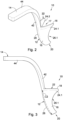
- a first embodiment of an orbital tissue retractor in accordance with the invention is designated by the reference numeral 10.
- the orbital tissue retractor is used for creating a passageway through orbital connective tissue surrounding the ocular globe N and the optic nerve sheath D and comprises an orbital tissue retractor body 12 and a handle 14 which extends from the orbital tissue retractor body for manipulating the retractor body.
- the orbital tissue retractor body comprises a channel formation 16 which defines a channel 17.
- the orbital tissue retractor body 12 has an open-ended C-shaped configuration when viewed in cross-sectional end view, with the orbital tissue retractor body having a relatively narrower distal insertion end 20 and a relatively wider proximal end 22.
- the orbital tissue retractor body has a generally tapered configuration wherein the tissue retractor body tapers from the proximal end thereof to the distal end thereof. The taper allows for easier insertion of the orbital tissue retractor body into orbital connective tissue.
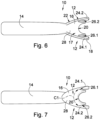
- the channel formation 16 has a pair of spaced side wall sections 24.1 and 24.2 for spacing orbital connective tissue from the ocular globe and the optic nerve sheath so as to create the passageway. End regions of the side wall sections 24.1, 24.2 define curved ocular abutment formations 26.1 and 26.2, respectively, for abutment with the ocular globe of the eye.
- the ocular abutment formations 26 have concave curved configurations conforming to the anatomical curvature of ocular globe.
- the distal end of the tissue retractor body is dimensioned and curved so as to conform to the anatomical shape of the optic nerve sheath so as to permit the optic nerve sheath to be received and cradled therein.
- the channel formation 16 has a curved configuration which conforms to the curvature of the orbit.
- the channel formation has a base wall section 28 extending between the side wall sections.
- the base wall section 28 has a first curved surface C1 extending between the side wall sections, when viewed in cross-sectional end view, which conforms to an anatomical curvature of the orbital rim of the cone-shaped orbit.
- the base wall section 28 has a second curved surface C2 extending between the proximal and distal ends of the orbital tissue retractor body, when viewed in side view, which conforms to an anatomical curvature of the ocular globe.
- the curvature of the second curved surface partly provides the orbital tissue retractor body with its tapered configuration reducing the distance between the base wall of the orbital tissue retractor body and the ocular globe when the distal end region of the orbital tissue retractor body is positioned within the orbit.
- the first and second curved surfaces of the base wall section of the tissue retractor wall extend orthogonally relative to one another.
- the orbital tissue retractor body 12 defines an outwardly flared collar 18 at the proximal end thereof.
- the collar 18 is configured and dimensioned so as to prevent conjunctival tissue from prolapsing and thereby obscuring the passageway, in use.
- the handle 14 is integrally formed with the orbital tissue retractor body 12 and includes a first section 42 which extends operatively upwardly from the base wall section 28, at the proximal end 22 of the orbital tissue retractor body 16 and a second section 44 which extends laterally outwardly from the first section so that the second section of the handle projects away from the orbit when an operation is performed on the eye by a surgeon holding the handle.
- the orbital tissue retractor 10 may be used for the insertion of a shunt insertion device 30 for use in the implantation of a shunt 50 providing for flow communication between aqueous fluid in the anterior chamber A of the eye and cerebrospinal fluid in the subarachnoid space B surrounding the optic nerve C.
- the shunt when implanted, regulates intraocular pressure in the eye of a human patient.
- the orbital tissue retractor body defines the passageway within which a shunt insertion device 30 and the shunt 50, is received.
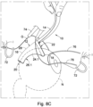
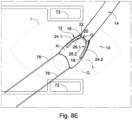
- FIGS 8A-8E the manner in which the orbital tissue retractor is used for implanting the head of the shunt into the subarachnoid space, is illustrated.
- Each eyelid is held open by means of an eyelid speculum 72 and an incision is made in Tenon's capsule G so as to access the Subtenon's space F (see Figure 8A ).
- Forceps 74 are used to open the Subtenon's space while bridle sutures 76 are used to rotate the eye.
- the distal end 20 of the orbital tissue retractor 10 is then passed into the Subtenon's space (see Figure 8B ).
- the tissue retracting device is pushed further into the Subtenon's space such that the curved ocular abutment walls 26.1, 26.2 follow the shape of the ocular globe when the tissue retractor body 12 is advanced towards the optic nerve (see Figure 8C ).
- the orbital tissue retractor body is then pushed into the Subtenon's space such that the ocular abutment formations 26.1, 26.2 are in abutment with the ocular globe and the optic nerve sheath is received within the concave curved distal end of the tissue retractor body (see Figure 8D ).
- the orbital tissue retractor body In this position, direct access to and visualisation of the optic nerve is provided via the internal passageway defined by the orbital tissue retractor body between the orbital connective tissue and the ocular globe and the optic nerve sheath.
- the orbital tissue retractor body is positioned relative to the ocular globe such that the conjunctiva H is located slightly under the flared collar 18, thereby preventing the conjunctival tissue from prolapsing into the passage and obscuring it.
- the curved ocular abutment formations rest against the orbital globe minimising distortion of tissues and preventing slippage while allowing access and visualisation of the optic nerve through the passageway.
- the orbital tissue retractor is manipulated into this position by the handle 14 which is held by a surgeon.
- Figure 8E a surgeon's view after insertion of the orbital tissue retractor body is shown wherein the cornea L has been rotated.
- the surgeon will be able to pass the tissue penetrating tip of the shunt inserting device 30 through the optic nerve sheath under direct visualisation.
- the shunt 50 can then be advanced into the subarachnoid space, whereafter the shunt inserting device is removed to leave the shunt lying with the distal end in the subarachnoid space.
- the Applicant believes that the entire process of positioning the orbital retractor in accordance with the invention will take approximately 10 minutes and will address the abovementioned difficulties experienced with gaining surgical access to the optic nerve.
- the process is relatively simple and minimally invasive.
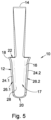
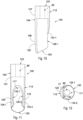
- a second embodiment of an orbital tissue retractor in accordance with the invention is designated by the reference numeral 100.
- the orbital tissue retractor 100 is used for creating a passageway through orbital connective tissue surrounding the ocular globe N and the optic nerve D.
- the orbital tissue retractor 100 is adapted for use with an endoscope 102 and comprises an orbital tissue retractor body 112 which is formed for abutment with the ocular globe N so as to displace orbital tissue from the orbital globe and define a passageway in the orbital connective tissue for the endoscope 102.
- the orbital tissue retractor body 112 has an open proximal end 122 and an open distal end 120.
- the orbital tissue retractor body has a proximal end section 104 and a distal end section 106 formed integrally therewith.
- the proximal end section 104 comprises a tubular formation 107 which has a hollow tubular configuration.
- the tubular formation 107 includes a support formation in the form of an internal passage 90 within which the endoscope 102 is received and supported.
- the internal passage 90 is dimensioned and configured to receive the endoscope therein in a snug supporting arrangement.
- the internal passage extends from the proximal end of the orbital tissue retractor body in an enlarged area within the distal end section.
- the distal end section 106 includes a channel formation 116 having a pair of spaced side wall sections 124.1 and 124.2 and a curved base wall section 128 which extends between the side wall sections.
- the base wall section 128 has a curved configuration which conforms to an anatomical curvature of the orbit. End regions of the side wall section 124.1, 124.2 define curved ocular abutment formations 126.1 and 126.2, respectively, for abutment with the ocular globe of the eye. More specifically, the base wall section 128 defines a first curved surface C1 extending between the side wall sections 124.1, 124.2, when viewed in cross-sectional end view, which conforms to the anatomical curvature of the orbital rim of the cone-shaped orbit.
- the base wall section 128 has a second curved surface C2 at a distal end region of the orbital tissue retractor body which, when viewed in side view, conforms to an anatomical curvature of the ocular globe.
- the distal end of the tissue retractor body is dimensioned and curved so as to conform to the anatomical shape of the optic nerve sheath D so as to permit the optic nerve sheath to be received and cradled therein.
- the orbital tissue retractor in accordance with the invention, provides a clear passageway through orbital tissues to the optic nerve preventing a prolapse of orbital fat into the passageway, while at the same time cradling the optic nerve at the distal end of the retractor.
Landscapes
- Health & Medical Sciences (AREA)
- Life Sciences & Earth Sciences (AREA)
- Surgery (AREA)
- Ophthalmology & Optometry (AREA)
- Animal Behavior & Ethology (AREA)
- Veterinary Medicine (AREA)
- Biomedical Technology (AREA)
- Heart & Thoracic Surgery (AREA)
- Engineering & Computer Science (AREA)
- Nuclear Medicine, Radiotherapy & Molecular Imaging (AREA)
- General Health & Medical Sciences (AREA)
- Public Health (AREA)
- Vascular Medicine (AREA)
- Molecular Biology (AREA)
- Medical Informatics (AREA)
- Physics & Mathematics (AREA)
- Biophysics (AREA)
- Optics & Photonics (AREA)
- Pathology (AREA)
- Radiology & Medical Imaging (AREA)
- Surgical Instruments (AREA)
- Prostheses (AREA)
- External Artificial Organs (AREA)
Claims (14)
- Augenhöhlengeweberetraktor (10, 100) für einen chirurgischen Eingriff im Bereich einer Augenhöhle, wobei der Augenhöhlengeweberetraktor (10, 100) einen Augenhöhlengeweberetraktorkörper (12, 112) umfasst, der ein offenes proximales Ende (22, 122) und ein offenes distales Ende (20, 120) aufweist und der gebildet ist, um an dem Augapfel des Auges anzuliegen, um Augenhöhlengewebe von dem Augapfel wegzuschieben,
dadurch gekennzeichnet, dass:der Augenhöhlengeweberetraktorkörper (12, 112) einen Durchgang für ein chirurgisches Instrument zwischen dem weggeschobenen Augenhöhlengewebe und dem Augapfel definiert,der Augenhöhlengeweberetraktorkörper (12, 112) eine Kanalformation (16, 116) mindestens an einem distalen Endbereich davon definiert, die:eine C-förmige Ausgestaltung aufweist, wenn sie in Querschnittsendansicht betrachtet wird;eine Krümmung aufweist, die der Krümmung der Sehnervscheide (D) entspricht, und die ein Aufnehmen der Sehnervscheide (D) darin erlaubt; undso ausgestaltet ist, dass sie den Sehnerv darin aufnimmt,wobei der distale Endbereich des Augenhöhlengeweberetraktorkörpers (12, 112) dimensioniert ist, um die Sehnervscheide (D) darin aufzunehmen und zu halten. - Augenhöhlengeweberetraktor (10, 100) nach einem der vorhergehenden Ansprüche, wobei der Augenhöhlengeweberetraktorkörper (12, 112) so dimensioniert ist, dass er innerhalb der Augenhöhle aufgenommen wird.
- Augenhöhlengeweberetraktor (10, 100) nach einem der vorhergehenden Ansprüche, wobei der Augenhöhlengeweberetraktorkörper (12, 112) eine gekrümmte Ausgestaltung aufweist, die einer anatomischen Krümmung der Augenhöhle entspricht.
- Augenhöhlengeweberetraktor (10, 100) nach einem der vorhergehenden Ansprüche, wobei die Kanalformation (16, 116) ein Paar beabstandeter Wandabschnitte (24.1, 24.2, 124.1, 124.2) aufweist, die konkave gekrümmte okulare Anlageformationen (26.1, 26.2, 126.1, 126.2) zur Anlage mit dem Augapfel definieren.
- Augenhöhlengeweberetraktor (10, 100) nach Anspruch 4, wobei die okularen Anlageformationen (26.1, 26.2, 126.1, 126.2) des Augenhöhlengeweberetraktorkörpers (12, 112) Krümmungen aufweisen, die einer anatomischen Krümmung des Augapfels entsprechen.
- Augenhöhlengeweberetraktor (10, 100) nach Anspruch 4 oder 5, wobei die Kanalformation (16, 116) einen Basiswandabschnitt (28, 128) aufweist, der sich zwischen den Seitenwandabschnitten erstreckt, wobei der Basiswandabschnitt (28, 128) eine erste Krümmung (C1) aufweist, die sich zwischen den Seitenwandabschnitten erstreckt, wenn sie in Querschnittsendansicht betrachtet wird, und die einer anatomischen Krümmung des Orbitalrandes der Augenhöhle entspricht, optional wobei der Basiswandabschnitt (28, 128) der Kanalformation (16, 116) eine zweite Krümmung (C2) mindestens an einem distalen Endbereich des Augenhöhlengeweberetraktorkörpers (12, 112) aufweist, die sich in eine Richtung zwischen dem proximalen und distalen Ende des Augenhöhlengeweberetraktorkörpers (12, 112) erstreckt, wenn sie in Seitenansicht betrachtet wird, und die einer anatomischen Krümmung des Augapfels entspricht.
- Augenhöhlengeweberetraktor (10, 100) nach einem der vorhergehenden Ansprüche, wobei das proximale Ende des Augenhöhlengeweberetraktorkörpers (12, 112) relativ breiter als das distale Ende davon ist, optional wobei sich der Augenhöhlengeweberetraktorkörper (12, 112) von dem proximalen Ende davon in Richtung des distalen Endes davon verjüngt.
- Augenhöhlengeweberetraktor (10, 100) nach einem der vorhergehenden Ansprüche, wobei sich die Kanalformation (16) des Augenhöhlengeweberetraktorkörpers (12, 112) von dem proximalen Ende zum distalen Ende davon erstreckt.
- Augenhöhlengeweberetraktor (10, 100) nach einem der vorhergehenden Ansprüche, der einen Griff (14) umfasst, der sich von dem Geweberetraktorkörper (12, 112) erstreckt und der gehalten werden kann, um den Geweberetraktorkörper (12, 112) zu betätigen.
- Augenhöhlengeweberetraktor (10, 100) nach Anspruch 9, wobei sich der Griff (14) von dem proximalen Ende des Geweberetraktorkörpers (12, 112) erstreckt.
- Augenhöhlengeweberetraktor (10, 100) nach einem der vorhergehenden Ansprüche, wobei der Augenhöhlengeweberetraktorkörper (12, 112) eine nach außen aufgeweitete Kragenformation an dem proximalen Ende davon umfasst, die so gebildet ist, dass verhindert wird, dass Bindehautsgewebe in den Durchgang für ein chirurgisches Instrument prolabiert und dadurch den Durchgang für ein chirurgisches Instrument in der Verwendung verdeckt.
- Augenhöhlengeweberetraktor (10, 100) nach einem der Ansprüche 1 bis 7, wobei der Augenhöhlengeweberetraktorkörper (12, 112) eine röhrenförmige Formation (107) aufweist, die eine hohle röhrenförmige Ausgestaltung an einem proximalen Endbereich davon aufweist, wobei der distale Endbereich die Kanalformation (16, 116) definiert, wobei der Durchgang für ein chirurgisches Instrument durch die röhrenförmige Formation (107) und die Kanalformation (16, 116) definiert wird.
- Augenhöhlengeweberetraktor (10, 100) nach Anspruch 12, wobei die röhrenförmige Formation (107) eine Abstützformation zum Abstützen eines Endoskops (102) umfasst.
- Augenhöhlengeweberetraktor (10, 100) nach Anspruch 13, wobei die Abstützformation in Form eines internen Durchgangs (90) innerhalb der röhrenförmigen Formation (107) vorliegt, innerhalb welcher das Endoskop aufgenommen und abgestützt ist.
Applications Claiming Priority (2)
| Application Number | Priority Date | Filing Date | Title |
|---|---|---|---|
| ZA201607546 | 2016-11-02 | ||
| PCT/IB2017/056816 WO2018083619A1 (en) | 2016-11-02 | 2017-11-02 | Orbital tissue retractor |
Publications (3)
| Publication Number | Publication Date |
|---|---|
| EP3534772A1 EP3534772A1 (de) | 2019-09-11 |
| EP3534772A4 EP3534772A4 (de) | 2020-07-01 |
| EP3534772B1 true EP3534772B1 (de) | 2024-11-27 |
Family
ID=62075587
Family Applications (2)
| Application Number | Title | Priority Date | Filing Date |
|---|---|---|---|
| EP17867123.6A Active EP3534772B1 (de) | 2016-11-02 | 2017-11-02 | Augenhöhlengeweberetraktor |
| EP17867263.0A Active EP3534854B1 (de) | 2016-11-02 | 2017-11-02 | Shunt-system und shunt zur behandlung von augenleiden |
Family Applications After (1)
| Application Number | Title | Priority Date | Filing Date |
|---|---|---|---|
| EP17867263.0A Active EP3534854B1 (de) | 2016-11-02 | 2017-11-02 | Shunt-system und shunt zur behandlung von augenleiden |
Country Status (10)
| Country | Link |
|---|---|
| US (3) | US11058580B2 (de) |
| EP (2) | EP3534772B1 (de) |
| JP (2) | JP7260082B2 (de) |
| CN (2) | CN110087593B (de) |
| BR (1) | BR212019008685Y1 (de) |
| ES (1) | ES3012650T3 (de) |
| PL (1) | PL3534772T3 (de) |
| RU (2) | RU2019115938A (de) |
| WO (2) | WO2018083620A1 (de) |
| ZA (2) | ZA201902253B (de) |
Families Citing this family (26)
| Publication number | Priority date | Publication date | Assignee | Title |
|---|---|---|---|---|
| WO2018083620A1 (en) * | 2016-11-02 | 2018-05-11 | Liqid Medical Proprietary Limited | A shunt system, shunt and method for treating an ocular disorder |
| WO2019018807A1 (en) | 2017-07-20 | 2019-01-24 | Shifamed Holdings, Llc | ADJUSTABLE FLOW GLAUCOMA DERIVATIVES AND METHODS OF MAKING AND USING SAME |
| US11166849B2 (en) | 2017-07-20 | 2021-11-09 | Shifamed Holdings, Llc | Adjustable flow glaucoma shunts and methods for making and using same |
| US12310619B2 (en) | 2017-12-01 | 2025-05-27 | Smith & Nephew, Inc. | Slotted canulla for arthroscopic surgery |
| WO2020150663A1 (en) | 2019-01-18 | 2020-07-23 | Shifamed Holdings, Llc | Adjustable flow glaucoma shunts and methods for making and using same |
| JP7614193B2 (ja) | 2019-10-10 | 2025-01-15 | シファメド・ホールディングス・エルエルシー | 流量調整可能な緑内障用シャントならびに関連システム及び方法 |
| AU2021209698A1 (en) | 2020-01-23 | 2022-08-04 | Shifamed Holdings, Llc | Adjustable flow glaucoma shunts and associated systems and methods |
| AU2021219845A1 (en) | 2020-02-14 | 2022-09-01 | Shifamed Holdings, Llc | Shunting systems with rotation-based flow control assemblies, and associated systems and methods |
| US11737920B2 (en) | 2020-02-18 | 2023-08-29 | Shifamed Holdings, Llc | Adjustable flow glaucoma shunts having non-linearly arranged flow control elements, and associated systems and methods |
| US11766355B2 (en) | 2020-03-19 | 2023-09-26 | Shifamed Holdings, Llc | Intraocular shunts with low-profile actuation elements and associated systems and methods |
| US11596550B2 (en) | 2020-04-16 | 2023-03-07 | Shifamed Holdings, Llc | Adjustable glaucoma treatment devices and associated systems and methods |
| CN115916125A (zh) * | 2020-06-11 | 2023-04-04 | 立奇得医疗私人有限公司 | 用于治疗青光眼的分流器和方法 |
| US11865283B2 (en) | 2021-01-22 | 2024-01-09 | Shifamed Holdings, Llc | Adjustable shunting systems with plate assemblies, and associated systems and methods |
| CN112957173B (zh) * | 2021-02-08 | 2022-02-25 | 青岛大学附属医院 | 一种用于眼眶骨手术的组织撑开装置 |
| WO2022236779A1 (en) * | 2021-05-13 | 2022-11-17 | Beijing Sightnovo Medical Technology Co., Ltd | Medical penetration and drainage for glaucoma treatment |
| WO2022236778A1 (en) | 2021-05-13 | 2022-11-17 | Beijing Sightnovo Medical Technology Co., Ltd | Medical penetration device and system |
| CN115337139B (zh) * | 2021-05-13 | 2025-02-25 | 中国医学科学院北京协和医院 | 眼部穿刺装置和眼部植入器具总成 |
| CN115337140B (zh) * | 2021-05-13 | 2025-01-10 | 中国医学科学院北京协和医院 | 眼部植入器具总成 |
| WO2023064810A1 (en) * | 2021-10-12 | 2023-04-20 | Khaderi Syed Khizer Rahim | Methods and systems for creating a fluid and pressure equilibrium between the sub-arachnoid space and the intraocular compartment |
| EP4493904A1 (de) | 2022-03-16 | 2025-01-22 | VivaScope GmbH | Probenvorbereitungsverfahren zur mikroskopischen untersuchung mit einem porösen material auf chitosanbasis |
| WO2024099427A1 (en) * | 2022-11-11 | 2024-05-16 | Beijing Sightnovo Medical Technology Co., Ltd | Integrated device and system for epidural injection |
| CN116942408A (zh) * | 2022-11-25 | 2023-10-27 | 苏州美视医疗合伙企业(有限合伙) | 眼科植入物输送装置 |
| CN115969613B (zh) * | 2022-12-23 | 2024-09-24 | 爱尔眼科医院集团四川眼科医院有限公司 | 一种巩膜缝合器 |
| WO2024145070A1 (en) * | 2022-12-27 | 2024-07-04 | University Of Miami | Z-kap scleral protector for treatment of conjunctiva with antimetabolites and other therapeutics during ophthalmic surgical procedures |
| CN119564130B (zh) * | 2025-02-06 | 2025-05-27 | 湖南省华芯医疗器械有限公司 | 压力平衡结构、内窥镜及置入系统 |
| CN120436689B (zh) * | 2025-07-09 | 2025-11-04 | 温州医科大学附属眼视光医院 | 一种用于经鼻微创采集微量视神经脑脊液的采集器 |
Family Cites Families (40)
| Publication number | Priority date | Publication date | Assignee | Title |
|---|---|---|---|---|
| US2555076A (en) * | 1947-11-17 | 1951-05-29 | Elijah R Crossley | Instrument for use in performing surgical eye operations |
| SU1560126A1 (ru) * | 1988-03-28 | 1990-04-30 | Научно-производственное объединение "Мединструмент" | Орбитальный ретрактор |
| US4995856A (en) * | 1989-06-14 | 1991-02-26 | Pudenz-Schulte Medical Research Corporation | Ventriculostomy reservoir |
| US6007511A (en) * | 1991-05-08 | 1999-12-28 | Prywes; Arnold S. | Shunt valve and therapeutic delivery system for treatment of glaucoma and methods and apparatus for its installation |
| US5300020A (en) * | 1991-05-31 | 1994-04-05 | Medflex Corporation | Surgically implantable device for glaucoma relief |
| US5171213A (en) * | 1991-08-14 | 1992-12-15 | Price Jr Francis W | Technique for fistulization of the eye and an eye filtration prosthesis useful therefor |
| US5346464A (en) * | 1992-03-10 | 1994-09-13 | Camras Carl B | Method and apparatus for reducing intraocular pressure |
| EP1029508A1 (de) | 1999-02-19 | 2000-08-23 | Gerrit Reinold Jacob Melles | Okulärspekulum sowie Verfahren zum Sperren der Augenlider |
| US6267752B1 (en) * | 1999-08-05 | 2001-07-31 | Medibell Medical Vision Technologies, Ltd. | Multi-functional eyelid speculum |
| US7488303B1 (en) * | 2002-09-21 | 2009-02-10 | Glaukos Corporation | Ocular implant with anchor and multiple openings |
| CA2457137A1 (en) * | 2001-08-16 | 2003-02-27 | Gmp Vision Solutions, Inc. | Improved shunt device and method for treating glaucoma |
| GB2382779B (en) | 2001-12-10 | 2006-06-28 | Fulcrum | Eye speculum |
| US8012115B2 (en) | 2003-02-18 | 2011-09-06 | S.K. Pharmaceuticals, Inc. | Optic nerve implants |
| US7354416B2 (en) * | 2003-02-18 | 2008-04-08 | Hugo Quiroz-Mercado | Methods and devices for draining fluids and lowering intraocular pressure |
| US8403828B2 (en) * | 2003-07-21 | 2013-03-26 | Vanderbilt University | Ophthalmic orbital surgery apparatus and method and image-guide navigation system |
| EP1689333B1 (de) * | 2003-12-05 | 2014-02-12 | Innfocus, Inc. | Verbesserte glaukom-implantationsvorrichtung |
| US20070027470A1 (en) * | 2005-07-07 | 2007-02-01 | Dodick Jack M | Surgical instrument |
| ES3042426T3 (en) * | 2006-01-17 | 2025-11-20 | Alcon Inc | Glaucoma treatment device |
| US8721702B2 (en) * | 2010-11-15 | 2014-05-13 | Aquesys, Inc. | Intraocular shunt deployment devices |
| US20120123316A1 (en) | 2010-11-15 | 2012-05-17 | Aquesys, Inc. | Intraocular shunts for placement in the intra-tenon's space |
| US8828070B2 (en) * | 2010-11-15 | 2014-09-09 | Aquesys, Inc. | Devices for deploying intraocular shunts |
| US8506515B2 (en) * | 2006-11-10 | 2013-08-13 | Glaukos Corporation | Uveoscleral shunt and methods for implanting same |
| US8353856B2 (en) | 2008-11-05 | 2013-01-15 | Abbott Medical Optics Inc. | Glaucoma drainage shunts and methods of use |
| US9168172B1 (en) * | 2009-02-25 | 2015-10-27 | Dr. John Berdahl | Process for treating glaucoma |
| EP3412260B1 (de) * | 2009-05-18 | 2020-08-26 | Dose Medical Corporation | Arzneimittelfreisetzendes augenimplantat |
| US9011326B2 (en) * | 2009-11-14 | 2015-04-21 | Spiway Llc | Soft tissue shield for trans-orbital surgery |
| EP2618777A1 (de) * | 2010-09-21 | 2013-07-31 | The Regents of the University of Colorado, a body corporate | Kammerwasser-mikrobypass-shunt |
| DE102010054333B4 (de) * | 2010-12-13 | 2019-05-29 | Stryker European Holdings I, LLC (n.d. Ges. d. Staates Delaware) | Chirurgischer Retraktor |
| US9005099B2 (en) * | 2011-02-15 | 2015-04-14 | Seros Medical, Llc | Method and apparatus for the delivery of photochemical (cross-linking) treatment to scleral tissue |
| ES2666857T3 (es) * | 2011-07-18 | 2018-05-08 | Mor-Research Applications Ltd. | Un dispositivo para ajustar la presión intraocular |
| EP2763592B1 (de) | 2011-10-05 | 2018-05-23 | MiniPumps, LLC | Instrumente zur chirurgischen grössensortierung und markierung |
| US9610195B2 (en) | 2013-02-27 | 2017-04-04 | Aquesys, Inc. | Intraocular shunt implantation methods and devices |
| WO2014078288A1 (en) * | 2012-11-14 | 2014-05-22 | Transcend Medical, Inc. | Flow promoting ocular implant |
| US10159600B2 (en) * | 2013-02-19 | 2018-12-25 | Aquesys, Inc. | Adjustable intraocular flow regulation |
| US9707128B2 (en) * | 2013-02-27 | 2017-07-18 | James M. Rynerson | Method and apparatus for reducing intraocular pressure of an eye |
| WO2014165124A1 (en) * | 2013-03-12 | 2014-10-09 | Oculeve, Inc. | Implant delivery devices, systems, and methods |
| EP2999430B1 (de) * | 2013-05-21 | 2019-11-13 | Novartis AG | Flussfördernde augenimplantatvorrichtung und verfahren |
| CN108403215B (zh) * | 2013-11-14 | 2021-03-23 | 阿奎西斯公司 | 眼内分流器插入器 |
| WO2015179708A1 (en) * | 2014-05-22 | 2015-11-26 | Invuity, Inc. | Medical device featuring cladded waveguide |
| WO2018083620A1 (en) * | 2016-11-02 | 2018-05-11 | Liqid Medical Proprietary Limited | A shunt system, shunt and method for treating an ocular disorder |
-
2017
- 2017-11-02 WO PCT/IB2017/056817 patent/WO2018083620A1/en not_active Ceased
- 2017-11-02 EP EP17867123.6A patent/EP3534772B1/de active Active
- 2017-11-02 EP EP17867263.0A patent/EP3534854B1/de active Active
- 2017-11-02 JP JP2019520743A patent/JP7260082B2/ja active Active
- 2017-11-02 US US16/342,372 patent/US11058580B2/en active Active
- 2017-11-02 PL PL17867123.6T patent/PL3534772T3/pl unknown
- 2017-11-02 RU RU2019115938A patent/RU2019115938A/ru unknown
- 2017-11-02 WO PCT/IB2017/056816 patent/WO2018083619A1/en not_active Ceased
- 2017-11-02 BR BR212019008685-0U patent/BR212019008685Y1/pt active IP Right Grant
- 2017-11-02 RU RU2019117105U patent/RU197527U1/ru active
- 2017-11-02 JP JP2019600125U patent/JP3223908U/ja active Active
- 2017-11-02 US US16/344,251 patent/US11883327B2/en active Active
- 2017-11-02 ES ES17867123T patent/ES3012650T3/es active Active
- 2017-11-02 CN CN201780067553.0A patent/CN110087593B/zh active Active
- 2017-11-02 CN CN201790001382.7U patent/CN210842975U/zh active Active
-
2019
- 2019-04-10 ZA ZA2019/02253A patent/ZA201902253B/en unknown
- 2019-04-10 ZA ZA2019/02254A patent/ZA201902254B/en unknown
-
2023
- 2023-12-13 US US18/538,591 patent/US20240122755A1/en not_active Abandoned
Also Published As
| Publication number | Publication date |
|---|---|
| WO2018083619A1 (en) | 2018-05-11 |
| EP3534772A1 (de) | 2019-09-11 |
| PL3534772T3 (pl) | 2025-04-22 |
| EP3534772A4 (de) | 2020-07-01 |
| EP3534854A1 (de) | 2019-09-11 |
| US11058580B2 (en) | 2021-07-13 |
| RU197527U1 (ru) | 2020-05-12 |
| CN210842975U (zh) | 2020-06-26 |
| WO2018083620A1 (en) | 2018-05-11 |
| US11883327B2 (en) | 2024-01-30 |
| CN110087593A (zh) | 2019-08-02 |
| CN110087593B (zh) | 2021-08-24 |
| RU2019115938A (ru) | 2020-12-03 |
| JP7260082B2 (ja) | 2023-04-18 |
| US20190261972A1 (en) | 2019-08-29 |
| US20190247231A1 (en) | 2019-08-15 |
| ZA201902254B (en) | 2019-12-18 |
| EP3534854A4 (de) | 2020-09-02 |
| ES3012650T3 (en) | 2025-04-09 |
| EP3534854B1 (de) | 2025-09-03 |
| RU2019115938A3 (de) | 2021-03-05 |
| US20240122755A1 (en) | 2024-04-18 |
| BR212019008685Y1 (pt) | 2022-07-26 |
| JP3223908U (ja) | 2019-11-14 |
| ZA201902253B (en) | 2019-12-18 |
| BR112019008830A2 (pt) | 2019-07-09 |
| JP2019532734A (ja) | 2019-11-14 |
| BR212019008685U2 (pt) | 2019-07-09 |
Similar Documents
| Publication | Publication Date | Title |
|---|---|---|
| EP3534772B1 (de) | Augenhöhlengeweberetraktor | |
| US12376988B2 (en) | Apparatus for delivering ocular implants into an anterior chamber of the eye | |
| US12343287B2 (en) | Methods and apparatus for treating glaucoma | |
| US9050169B2 (en) | Methods and apparatus for delivering ocular implants into the eye | |
| US8337509B2 (en) | Methods and apparatus for delivering ocular implants into the eye | |
| US8377122B2 (en) | Ocular implant with stiffness qualities, methods of implantation and system | |
| ES2882522T3 (es) | Dispositivo de implante de glaucoma | |
| CN104000684A (zh) | 用于降低眼睛中眼内压的方法和装置 | |
| US10814132B2 (en) | Retinal implant with insertion cord | |
| CA2522956A1 (en) | Opthalmic microsurgical instruments | |
| JP2004337551A (ja) | 水晶体嚢保持器具 | |
| CN112451207B (zh) | 用于植入视网膜植入体的手术器械组件 | |
| Agosti et al. | 360° around the orbit: key surgical anatomy of the microsurgical and endoscopic cranio-orbital and orbitocranial approaches | |
| EP0507894A1 (de) | Aufblasbarer Ballon zur Behandlung von Netzhautablösungen |
Legal Events
| Date | Code | Title | Description |
|---|---|---|---|
| STAA | Information on the status of an ep patent application or granted ep patent |
Free format text: STATUS: THE INTERNATIONAL PUBLICATION HAS BEEN MADE |
|
| PUAI | Public reference made under article 153(3) epc to a published international application that has entered the european phase |
Free format text: ORIGINAL CODE: 0009012 |
|
| STAA | Information on the status of an ep patent application or granted ep patent |
Free format text: STATUS: REQUEST FOR EXAMINATION WAS MADE |
|
| 17P | Request for examination filed |
Effective date: 20190524 |
|
| AK | Designated contracting states |
Kind code of ref document: A1 Designated state(s): AL AT BE BG CH CY CZ DE DK EE ES FI FR GB GR HR HU IE IS IT LI LT LU LV MC MK MT NL NO PL PT RO RS SE SI SK SM TR |
|
| AX | Request for extension of the european patent |
Extension state: BA ME |
|
| DAV | Request for validation of the european patent (deleted) | ||
| DAX | Request for extension of the european patent (deleted) | ||
| A4 | Supplementary search report drawn up and despatched |
Effective date: 20200604 |
|
| RIC1 | Information provided on ipc code assigned before grant |
Ipc: A61F 9/00 20060101ALI20200528BHEP Ipc: A61B 17/02 20060101ALI20200528BHEP Ipc: A61F 9/007 20060101ALI20200528BHEP Ipc: A61B 1/32 20060101AFI20200528BHEP Ipc: A61B 3/00 20060101ALI20200528BHEP |
|
| GRAP | Despatch of communication of intention to grant a patent |
Free format text: ORIGINAL CODE: EPIDOSNIGR1 |
|
| STAA | Information on the status of an ep patent application or granted ep patent |
Free format text: STATUS: GRANT OF PATENT IS INTENDED |
|
| INTG | Intention to grant announced |
Effective date: 20240621 |
|
| GRAS | Grant fee paid |
Free format text: ORIGINAL CODE: EPIDOSNIGR3 |
|
| GRAA | (expected) grant |
Free format text: ORIGINAL CODE: 0009210 |
|
| STAA | Information on the status of an ep patent application or granted ep patent |
Free format text: STATUS: THE PATENT HAS BEEN GRANTED |
|
| AK | Designated contracting states |
Kind code of ref document: B1 Designated state(s): AL AT BE BG CH CY CZ DE DK EE ES FI FR GB GR HR HU IE IS IT LI LT LU LV MC MK MT NL NO PL PT RO RS SE SI SK SM TR |
|
| REG | Reference to a national code |
Ref country code: GB Ref legal event code: FG4D |
|
| REG | Reference to a national code |
Ref country code: CH Ref legal event code: EP |
|
| P01 | Opt-out of the competence of the unified patent court (upc) registered |
Free format text: CASE NUMBER: APP_60099/2024 Effective date: 20241106 |
|
| REG | Reference to a national code |
Ref country code: IE Ref legal event code: FG4D |
|
| REG | Reference to a national code |
Ref country code: DE Ref legal event code: R096 Ref document number: 602017086455 Country of ref document: DE |
|
| REG | Reference to a national code |
Ref country code: LT Ref legal event code: MG9D |
|
| REG | Reference to a national code |
Ref country code: NL Ref legal event code: MP Effective date: 20241127 |
|
| REG | Reference to a national code |
Ref country code: ES Ref legal event code: FG2A Ref document number: 3012650 Country of ref document: ES Kind code of ref document: T3 Effective date: 20250409 |
|
| PG25 | Lapsed in a contracting state [announced via postgrant information from national office to epo] |
Ref country code: PT Free format text: LAPSE BECAUSE OF FAILURE TO SUBMIT A TRANSLATION OF THE DESCRIPTION OR TO PAY THE FEE WITHIN THE PRESCRIBED TIME-LIMIT Effective date: 20250327 Ref country code: IS Free format text: LAPSE BECAUSE OF FAILURE TO SUBMIT A TRANSLATION OF THE DESCRIPTION OR TO PAY THE FEE WITHIN THE PRESCRIBED TIME-LIMIT Effective date: 20250327 Ref country code: HR Free format text: LAPSE BECAUSE OF FAILURE TO SUBMIT A TRANSLATION OF THE DESCRIPTION OR TO PAY THE FEE WITHIN THE PRESCRIBED TIME-LIMIT Effective date: 20241127 |
|
| PG25 | Lapsed in a contracting state [announced via postgrant information from national office to epo] |
Ref country code: FI Free format text: LAPSE BECAUSE OF FAILURE TO SUBMIT A TRANSLATION OF THE DESCRIPTION OR TO PAY THE FEE WITHIN THE PRESCRIBED TIME-LIMIT Effective date: 20241127 Ref country code: NL Free format text: LAPSE BECAUSE OF FAILURE TO SUBMIT A TRANSLATION OF THE DESCRIPTION OR TO PAY THE FEE WITHIN THE PRESCRIBED TIME-LIMIT Effective date: 20241127 |
|
| REG | Reference to a national code |
Ref country code: AT Ref legal event code: MK05 Ref document number: 1744866 Country of ref document: AT Kind code of ref document: T Effective date: 20241127 |
|
| PG25 | Lapsed in a contracting state [announced via postgrant information from national office to epo] |
Ref country code: BG Free format text: LAPSE BECAUSE OF FAILURE TO SUBMIT A TRANSLATION OF THE DESCRIPTION OR TO PAY THE FEE WITHIN THE PRESCRIBED TIME-LIMIT Effective date: 20241127 |
|
| PG25 | Lapsed in a contracting state [announced via postgrant information from national office to epo] |
Ref country code: NO Free format text: LAPSE BECAUSE OF FAILURE TO SUBMIT A TRANSLATION OF THE DESCRIPTION OR TO PAY THE FEE WITHIN THE PRESCRIBED TIME-LIMIT Effective date: 20250227 |
|
| PG25 | Lapsed in a contracting state [announced via postgrant information from national office to epo] |
Ref country code: LV Free format text: LAPSE BECAUSE OF FAILURE TO SUBMIT A TRANSLATION OF THE DESCRIPTION OR TO PAY THE FEE WITHIN THE PRESCRIBED TIME-LIMIT Effective date: 20241127 Ref country code: AT Free format text: LAPSE BECAUSE OF FAILURE TO SUBMIT A TRANSLATION OF THE DESCRIPTION OR TO PAY THE FEE WITHIN THE PRESCRIBED TIME-LIMIT Effective date: 20241127 |
|
| PG25 | Lapsed in a contracting state [announced via postgrant information from national office to epo] |
Ref country code: RS Free format text: LAPSE BECAUSE OF FAILURE TO SUBMIT A TRANSLATION OF THE DESCRIPTION OR TO PAY THE FEE WITHIN THE PRESCRIBED TIME-LIMIT Effective date: 20250227 |
|
| REG | Reference to a national code |
Ref country code: GR Ref legal event code: EP Ref document number: 20250400397 Country of ref document: GR Effective date: 20250409 |
|
| PG25 | Lapsed in a contracting state [announced via postgrant information from national office to epo] |
Ref country code: SM Free format text: LAPSE BECAUSE OF FAILURE TO SUBMIT A TRANSLATION OF THE DESCRIPTION OR TO PAY THE FEE WITHIN THE PRESCRIBED TIME-LIMIT Effective date: 20241127 |
|
| PG25 | Lapsed in a contracting state [announced via postgrant information from national office to epo] |
Ref country code: DK Free format text: LAPSE BECAUSE OF FAILURE TO SUBMIT A TRANSLATION OF THE DESCRIPTION OR TO PAY THE FEE WITHIN THE PRESCRIBED TIME-LIMIT Effective date: 20241127 |
|
| PG25 | Lapsed in a contracting state [announced via postgrant information from national office to epo] |
Ref country code: EE Free format text: LAPSE BECAUSE OF FAILURE TO SUBMIT A TRANSLATION OF THE DESCRIPTION OR TO PAY THE FEE WITHIN THE PRESCRIBED TIME-LIMIT Effective date: 20241127 |
|
| PG25 | Lapsed in a contracting state [announced via postgrant information from national office to epo] |
Ref country code: RO Free format text: LAPSE BECAUSE OF FAILURE TO SUBMIT A TRANSLATION OF THE DESCRIPTION OR TO PAY THE FEE WITHIN THE PRESCRIBED TIME-LIMIT Effective date: 20241127 |
|
| PG25 | Lapsed in a contracting state [announced via postgrant information from national office to epo] |
Ref country code: SK Free format text: LAPSE BECAUSE OF FAILURE TO SUBMIT A TRANSLATION OF THE DESCRIPTION OR TO PAY THE FEE WITHIN THE PRESCRIBED TIME-LIMIT Effective date: 20241127 |
|
| PG25 | Lapsed in a contracting state [announced via postgrant information from national office to epo] |
Ref country code: CZ Free format text: LAPSE BECAUSE OF FAILURE TO SUBMIT A TRANSLATION OF THE DESCRIPTION OR TO PAY THE FEE WITHIN THE PRESCRIBED TIME-LIMIT Effective date: 20241127 |
|
| REG | Reference to a national code |
Ref country code: DE Ref legal event code: R097 Ref document number: 602017086455 Country of ref document: DE |
|
| PG25 | Lapsed in a contracting state [announced via postgrant information from national office to epo] |
Ref country code: SE Free format text: LAPSE BECAUSE OF FAILURE TO SUBMIT A TRANSLATION OF THE DESCRIPTION OR TO PAY THE FEE WITHIN THE PRESCRIBED TIME-LIMIT Effective date: 20241127 |
|
| PLBE | No opposition filed within time limit |
Free format text: ORIGINAL CODE: 0009261 |
|
| STAA | Information on the status of an ep patent application or granted ep patent |
Free format text: STATUS: NO OPPOSITION FILED WITHIN TIME LIMIT |
|
| PGFP | Annual fee paid to national office [announced via postgrant information from national office to epo] |
Ref country code: PL Payment date: 20250912 Year of fee payment: 9 |
|
| 26N | No opposition filed |
Effective date: 20250828 |