EP3534081A1 - Deterioration diagnosis device and air conditioner - Google Patents
Deterioration diagnosis device and air conditioner Download PDFInfo
- Publication number
- EP3534081A1 EP3534081A1 EP16919783.7A EP16919783A EP3534081A1 EP 3534081 A1 EP3534081 A1 EP 3534081A1 EP 16919783 A EP16919783 A EP 16919783A EP 3534081 A1 EP3534081 A1 EP 3534081A1
- Authority
- EP
- European Patent Office
- Prior art keywords
- degradation
- compressor
- vibration
- vibration detection
- unit
- Prior art date
- Legal status (The legal status is an assumption and is not a legal conclusion. Google has not performed a legal analysis and makes no representation as to the accuracy of the status listed.)
- Granted
Links
Images




Classifications
-
- F—MECHANICAL ENGINEERING; LIGHTING; HEATING; WEAPONS; BLASTING
- F04—POSITIVE - DISPLACEMENT MACHINES FOR LIQUIDS; PUMPS FOR LIQUIDS OR ELASTIC FLUIDS
- F04B—POSITIVE-DISPLACEMENT MACHINES FOR LIQUIDS; PUMPS
- F04B49/00—Control, e.g. of pump delivery, or pump pressure of, or safety measures for, machines, pumps, or pumping installations, not otherwise provided for, or of interest apart from, groups F04B1/00 - F04B47/00
- F04B49/10—Other safety measures
-
- F—MECHANICAL ENGINEERING; LIGHTING; HEATING; WEAPONS; BLASTING
- F04—POSITIVE - DISPLACEMENT MACHINES FOR LIQUIDS; PUMPS FOR LIQUIDS OR ELASTIC FLUIDS
- F04B—POSITIVE-DISPLACEMENT MACHINES FOR LIQUIDS; PUMPS
- F04B51/00—Testing machines, pumps, or pumping installations
-
- F—MECHANICAL ENGINEERING; LIGHTING; HEATING; WEAPONS; BLASTING
- F04—POSITIVE - DISPLACEMENT MACHINES FOR LIQUIDS; PUMPS FOR LIQUIDS OR ELASTIC FLUIDS
- F04C—ROTARY-PISTON, OR OSCILLATING-PISTON, POSITIVE-DISPLACEMENT MACHINES FOR LIQUIDS; ROTARY-PISTON, OR OSCILLATING-PISTON, POSITIVE-DISPLACEMENT PUMPS
- F04C28/00—Control of, monitoring of, or safety arrangements for, pumps or pumping installations specially adapted for elastic fluids
- F04C28/28—Safety arrangements; Monitoring
-
- F—MECHANICAL ENGINEERING; LIGHTING; HEATING; WEAPONS; BLASTING
- F04—POSITIVE - DISPLACEMENT MACHINES FOR LIQUIDS; PUMPS FOR LIQUIDS OR ELASTIC FLUIDS
- F04D—NON-POSITIVE-DISPLACEMENT PUMPS
- F04D27/00—Control, e.g. regulation, of pumps, pumping installations or pumping systems specially adapted for elastic fluids
- F04D27/001—Testing thereof; Determination or simulation of flow characteristics; Stall or surge detection, e.g. condition monitoring
-
- G—PHYSICS
- G01—MEASURING; TESTING
- G01M—TESTING STATIC OR DYNAMIC BALANCE OF MACHINES OR STRUCTURES; TESTING OF STRUCTURES OR APPARATUS, NOT OTHERWISE PROVIDED FOR
- G01M7/00—Vibration-testing of structures; Shock-testing of structures
- G01M7/02—Vibration-testing by means of a shake table
-
- F—MECHANICAL ENGINEERING; LIGHTING; HEATING; WEAPONS; BLASTING
- F04—POSITIVE - DISPLACEMENT MACHINES FOR LIQUIDS; PUMPS FOR LIQUIDS OR ELASTIC FLUIDS
- F04B—POSITIVE-DISPLACEMENT MACHINES FOR LIQUIDS; PUMPS
- F04B2207/00—External parameters
- F04B2207/70—Warnings
Definitions
- the present invention relates to a degradation diagnostic device, which is configured to diagnose degradation of a compressor, and to an air-conditioning apparatus.
- Patent Literature 1 discloses a technology of predicting a lifetime of a compressor based on a vibration detection value obtained by an acceleration sensor that is mounted to a leg portion of the compressor.
- An air-conditioning apparatus disclosed in Patent Literature 2 includes a terminal cover provided on a peripheral surface of a shell of a compressor and stops the compressor when a vibration detection value obtained by an acceleration sensor provided inside the terminal cover indicates an abnormality.
- the leg portion of the compressor is located at a position to which vibration of the compressor caused by, for example, a rotational motion of a compression mechanism unit is unlikely to be transmitted.
- the terminal cover that covers a power supply connection portion is generally provided at a position to which the vibration of the compressor is unlikely to be transmitted.
- the terminal cover has low fixation strength.
- noise tends to be mixed with the vibration detection value obtained by the acceleration sensor that is provided inside the terminal cover. Therefore, there is a problem in detection accuracy.
- the vibration caused by, for example, the rotational motion of the compression mechanism unit cannot be detected with high accuracy. Therefore, a problem arises that a degree of degradation of the compressor cannot be precisely diagnosed.
- the present invention has been made to solve the problems described above, and an object thereof is to provide a degradation diagnostic device, which is capable of detecting vibration caused by, for example, a rotational motion of a compression mechanism unit with high accuracy to perform a highly accurate degradation diagnosis for a compressor, and an air-conditioning apparatus.
- a degradation diagnostic device configured to perform a diagnosis for degradation of a compressor including a compression mechanism unit to be driven along with a rotational motion of a rotary shaft and a shell forming an outer casing, the degradation diagnostic device including a vibration detection device to be fixed onto an outer wall of the shell at a position at which the compression mechanism unit is located, in which the vibration detection device includes: a vibration sensor configured to detect vibration of the compressor; a sensor holding unit including the vibration sensor; a base portion to which the sensor holding unit is connected; and a plurality of projecting portions formed on a surface of the base portion on a side opposite to the sensor holding unit and to be brought into contact with the outer wall.
- an air-conditioning apparatus including: a refrigeration cycle, through which refrigerant circulates, the refrigeration cycle being formed by connecting, by a refrigerant pipe, a compressor, which includes a compression mechanism unit to be driven along with a rotational motion of a rotary shaft and is configured to compress the refrigerant, a heat source-side heat exchanger configured to exchange heat between a heat medium and the refrigerant, a pressure reducing device, which is configured to regulate a flow rate of the refrigerant, and a use-side heat exchanger configured to exchange heat between an indoor air and the refrigerant; and the degradation diagnostic device described above.
- the sensor holding unit including the vibration sensor is formed integrally with the plurality of projecting portions which are brought into contact with the outer wall of the shell at the position at which the compression mechanism unit is located. Therefore, the vibration caused by, for example, the rotational motion of the compression mechanism unit can be detected by the vibration sensor with high accuracy. Thus, the highly accurate degradation diagnosis for the compressor can be performed.
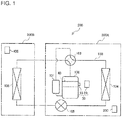
- FIG. 1 is a configuration diagram of an air-conditioning apparatus and a degradation diagnostic device according to Embodiment 1 of the present invention.
- an air-conditioning apparatus 200 includes an outdoor unit 200A, which is installed outdoors, and an indoor unit 200B, which is installed indoors.
- the outdoor unit 200A includes a compressor 100, a suction muffler 101 connected to a suction side of the compressor 100, and a four-way valve 103 connected to a discharge side of the compressor 100.
- the outdoor unit 200A includes a heat source-side heat exchanger 104, which is formed of, for example, a fin-and-tube type heat exchanger and is configured to exchange heat between an outdoor air and refrigerant, and a pressure reducing device 105, which is formed of, for example, an electric expansion valve and is configured to regulate a flow rate of the refrigerant.
- the indoor unit 200B includes a use-side heat exchanger 106, which is formed of, for example, a fin-and-tube type heat exchanger and is configured to exchange heat between an indoor air and the refrigerant.
- the air-conditioning apparatus 200 has a refrigeration cycle through which the refrigerant circulates, which is formed by connecting the compressor 100, the suction muffler 101, the four-way valve 103, the heat source-side heat exchanger 104, the pressure reducing device 105, and the use-side heat exchanger 106 by a refrigerant pipe 150.
- the compressor 100 is configured to suck refrigerant in a low-pressure gaseous state and compress the refrigerant into refrigerant in a high-pressure gaseous state.
- the compressor 100 may be one which is capable of appropriately changing an operating frequency by inverter control or may be operated at a constant velocity without a function of changing the operating frequency.
- various compressors such as a scroll-type compressor, a rotary-type compressor, a reciprocating-type compressor, a helical-type compressor, and a turbo-type compressor can be adopted.
- the four-way valve 103 is configured to switch flow of the refrigerant from the compressor 100.
- the four-way valve 103 is, for example, connected to a side indicated by the solid line of Fig. 1 during a heating operation and is connected to a side indicated by the broken line of Fig. 1 during a cooling operation.
- the outdoor unit 200A includes a controller 300, which is configured to control the refrigeration cycle. Specifically, the controller 300 is configured to control, for example, the operation frequency of the compressor 100, processing for switching the four-way valve 103, and an opening degree of the pressure reducing device 105.
- the outdoor unit 200A includes a degradation diagnostic device 30.
- the degradation diagnostic device 30 includes a vibration detection device 10 and a diagnostic processing device 20.
- the vibration detection device 10 and the diagnostic processing device 20 are connected in a wired or wireless manner.
- the diagnostic processing device 20 is configured to acquire vibration detection values detected by a first vibration sensor 12a and a second vibration sensor 12b in a wired or wireless manner from the vibration detection device 10.
- the indoor unit 200B includes a display unit 400, which is formed of, for example, a liquid crystal display (LCD).
- LCD liquid crystal display
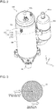
- Fig. 2 is an external view illustrating the compressor and the vibration detection device of Fig. 1 .
- Fig. 3 is an explanatory view schematically illustrating a cross section of a compression mechanism unit and a shell of Fig. 2 , which is taken along an xy plane.
- the compressor 100 includes a shell 50 and a leg portion 60.
- the shell 50 forms an outer casing of the compressor 100.
- the compressor 100 includes a compression mechanism unit 40, which is driven along with a rotational motion of a rotary shaft (not shown), inside the shell 50.
- the compression mechanism unit 40 is coupled to an electric motor (not shown) through intermediation of the rotary shaft.
- the rotary shaft transmits a rotational force of the electric motor to the compression mechanism unit 40.
- a discharge pipe 100a is provided to the compressor 100, whereas a suction pipe 101a is provided to the suction muffler 101.
- the compression mechanism unit 40 is vibrated by a rotational motion or a reciprocating motion of an internal movable component, and the vibration thereof is transmitted to the shell 50.
- the vibration of the compression mechanism unit 40 is more intensely transmitted to a portion of the shell 50, which is positioned on an outer periphery of the compression mechanism unit 40.
- the compression mechanism unit 40 repeats a predetermined motion pattern in a given cycle. Therefore, a vibration pattern generated due to the motion of the movable component of the compression mechanism unit 40 is transmitted to the shell 50.
- the vibration detection device 10 is fixed to an outer wall of the shell 50 at a position at which the compression mechanism unit 40 is located, as illustrated in Fig. 2 .
- the vibration detection device 10 includes a sensor holding unit 12, which includes the first vibration sensor 12a, the second vibration sensor 12b, and a holding member 12c.
- the sensor holding unit 12 includes the first vibration sensor 12a and the second vibration sensor 12b, which are provided to the holding member 12c.
- the vibration detection device 10 includes a mounting portion 11, which is connected to the sensor holding unit 12. The mounting portion 11 is located on a side close to the compressor 100 with respect to the sensor holding unit 12 under a state in which the vibration detection device 10 is fixed to the compressor 100.
- the first vibration sensor 12a and the second vibration sensor 12b are arranged so that a vibration detection direction matches a direction of the motion of the movable component of the compression mechanism unit 40.
- the direction of the motion of the movable component of the compression mechanism unit 40 includes a tangential direction T, which is a direction of a tangent of a rotation trajectory of the compression mechanism unit 40, and a circle center direction Co, which is a direction from the outer wall of the shell 50 toward a center of the compression mechanism unit 40.
- the first vibration sensor 12a is arranged so that the vibration detection direction matches the tangential direction T.
- the second vibration sensor 12b is arranged so that the vibration detection direction matches the circle center direction Co.
- the first vibration sensor 12a detects vibration along the tangential direction T of the compressor 100, which is caused by the rotational motion of the movable component of the compression mechanism unit 40, as a first vibration detection value.
- the second vibration sensor 12b detects vibration along the circle center direction Co of the compressor 100, which is caused by the reciprocating motion of the movable component of the compression mechanism unit 40, as a second vibration detection value.
- the tangential direction T is parallel to an x-axis direction
- the circle center direction Co is parallel to a y-axis direction
- an axial direction of the rotary shaft corresponds to a z-axis direction.
- the tangential direction T is a direction orthogonal to a diametrical direction of the shell 50 on an xy cross section
- the circle center direction Co corresponds to the diametrical direction of the shell 50 on the xy cross section.
- the first vibration sensor 12a and the second vibration sensor 12b are semiconductor-type micro electro mechanical system (MEMS) sensors, which are included in acceleration sensors configured to detect a vibrational acceleration.
- MEMS micro electro mechanical system
- capacitive type or piezoresistive type MEMS sensors are used as the first vibration sensor 12a and the second vibration sensor 12b in view of a degree of increase in surface temperature of the shell 50.
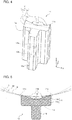
- Fig. 4 is an enlarged perspective view illustrating the vibration detection device 10 of Fig. 2 .
- Fig. 5 is a schematic sectional view illustrating a state in which the vibration detection device 10 of Fig. 4 is taken along the xy plane. A specific structure of the vibration detection device 10 is described with reference to Fig. 4 and Fig. 5 .
- the holding member 12c is formed into a cuboidal shape of which the z-axis direction is the longitudinal direction.
- the mounting portion 11 includes a base portion 11a connected to the holding member 12c and two projecting portions 11b provided on a surface of the base portion 11a, which is located on a side opposite to the holding member 12c.
- a central portion of the base portion 11a in the y-axis direction is connected to the holding member 12c.
- the base portion 11a is formed into a cuboidal shape of which the z-axis direction is the longitudinal direction and the length in the y-axis direction is larger than that of the holding member 12c.
- Each of the projecting portions 11b has an inner wall 11d, which is located on a side opposite to the sensor holding unit 12.
- the two projecting portions 11b form, with the respective inner walls 11d, a V-shaped outer wall on the xy cross section.
- each of the projecting portions 11b is formed into a triangular prism shape of which the z-axis direction is a longitudinal direction.
- the projecting portion 11b has a right triangular xy cross section having the inner wall 11d as a hypotenuse.
- a weight of the vibration detection device 10 is in a range of from 2 g to 10 g, a magnet having a magnetic force ranging from about 11 N to about 53 N is only required to be used.
- the vibration detection device 10 can be fixed to the compressor 100 under a state in which distal end portions 11c are held in contact with the outer wall of the shell 50.
- a magnet may be embedded partly, not entirely, in the mounting portion 11 as long as the magnetic force sufficient for stably fixing the vibration detection device 10 to the shell 50 can be obtained.
- a magnet may be provided in each of the two projecting portions 11b.
- the magnet a sheet-shaped magnet or a rod-shaped magnet may be adopted. In this case, it is preferred that the magnet be embedded in a main body of the mounting portion 11 so that a longitudinal direction of the magnet matches a longitudinal direction of the mounting portion 11.
- the vibration detection device 10 which is lightweight as in the example described above, can be formed.
- the vibration detection device 10 can be easily fixed onto the outer wall of the shell 50 at the position at which the compression mechanism unit 40 is located for use.
- the main body of the mounting portion 11 and the holding member 12c are made of engineering plastic or fiber-reinforced plastic, which is excellent in performance such as a mechanical strength, a heat resistance, and a wear resistance as compared to those of commodity plastics.
- the low-pressure shell type compressor 100 has a lower surface temperature than a surface temperature of the high-pressure shell type compressor 100. Therefore, when the vibration detection device 10 is mounted to the low-pressure shell type compressor 100, the main body of the mounting portion 11 and the holding member 12c can be made of plastic having a relatively low heat resistance. It is apparent that the mounting portion 11 and the holding member 12c may be made of different materials.
- the mounting portion 11 may be formed entirely of a magnet.
- each of the two projecting portions 11b of the mounting portion 11 may be formed of a magnet.
- a central angle ⁇ which is an angle formed between the inner walls 11d of the two projecting portions 11b, is set based on curvatures of the shells 50 of various types of the compressors 100. More specifically, when a center of the shell 50 is a center O for the compressors 100 having various sizes, to which the vibration detection device 10 is supposed to be fixed, the central angle ⁇ is set so that a distance between the center O and each of the distal end portions 11c becomes equal to or smaller than a distance between the center O and a central portion 11 e.
- an outer wall S, an outer wall M, and an outer wall L are exemplified as the outer walls of the shells 50, which have different curvatures, specifically, different diameters.
- the diameters of the shells 50 increase in the order of the outer wall S, the outer wall M, and the outer wall L.
- both of the distal end portions 11c of the two projecting portions 11b are held in contact with each of the outer wall S, the outer wall M, and the outer wall L.
- the vibration detection device 10 can be mounted to various compressors 100 having different sizes for use.
- the distal end portion 11c of each of the projecting portions 11b has a pointed shape.
- the distal end portion 11c is formed so as to be held in linear contact with the shell 50 along the axial direction of the rotary shaft under a state in which the mounting portion 11 is fixed to the shell 50. Therefore, dew condensation generated on a surface of the compressor 100 flows from a portion in which the projecting portions 11b are not held in contact with the shell 50. Therefore, adhesion of the dew condensation to the first vibration sensor 12a and the second vibration sensor 12b can be prevented.
- the vibration detection device 10 is fixed to the compressor 100 under a state in which the distal end portions 11c located at the distal ends of the mounting portion 11 are held in contact with the shell 50.
- the distal end portions 11c may be formed smoothly and rounded. Even with such a shape, the mounting portion 11 of the vibration detection device 10 can be fixed to the shell 50 under a state in which the distal end portions 11c are held in linear contact with the shell 50 along the axial direction of the rotary shaft. Therefore, the adhesion of the dew condensation to the first vibration sensor 12a and the second vibration sensor 12b can be prevented.
- each of the first vibration sensor 12a and the second vibration sensor 12b is provided so that the vibration detection direction is at a right angle relative to the distal end portions 11c formed along the axial direction of the rotary shaft. Therefore, through the contact of the distal end portions 11c with the shell 50 along the axial direction of the rotary shaft, the first vibration sensor 12a can detect the vibration along the tangential direction T and the second vibration sensor 12b can detect the vibration along the circle center direction Co.
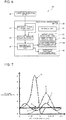
- Fig. 6 is a block diagram illustrating a functional configuration of the diagnostic processing device 20 of Fig. 1 .
- the diagnostic processing device 20 includes a storage unit 21, a stability determining unit 22, a feature amount computing unit 23, a degradation determining unit 24, a notification processing unit 25, and an operation switching processing unit 26.
- an operation program and various control parameters for the diagnostic processing device 20 and other data are stored.
- one or a plurality of degradation threshold values each serving as a standard of degradation determination of the compressor 100 by the degradation determining unit 24 are stored.
- the stability determining unit 22 is configured to determine whether or not a state of the air-conditioning apparatus 200 has been stabilized. For example, the stability determining unit 22 may determine whether or not the state of the air-conditioning apparatus 200 has been stabilized by determining whether or not a rotation speed of the compressor 100 has become constant. Alternatively, the stability determining unit 22 may determine whether or not the state of the air-conditioning apparatus 200 has been stabilized by determining whether or not a state of the refrigeration cycle has been maintained in the same state for a preset time period or longer. In this case, the state of the refrigeration cycle includes a state such as a temperature and a pressure of the refrigerant circulating through the refrigeration cycle. The preset time period is set to, for example, three minutes. The stability determining unit 22 may determine stability of the state of the air-conditioning apparatus 200 with use of at least one of the first vibration detection value and the second vibration detection value.
- the feature amount computing unit 23 is configured to compute a feature amount indicative of the state of the compressor 100 with use of at least one of the first vibration detection value detected by the first vibration sensor 12a and the second vibration detection value detected by the second vibration sensor 12b.
- the feature amount computing unit 23 has a function of computing a plurality of different feature amounts at the same timing.
- the feature amount computing unit 23 can compute, for example, a standard deviation, a median, an average value, a peak value, an impact index, a form factor, a peak-to-rms ratio, a skewness, a kurtosis, an extreme value of the skewness, an extreme value of the kurtosis, an extreme value of the average value, an average frequency, a crossover frequency, or an extreme value frequency as the feature amount.
- the feature amount computing unit 23 uses a maximum value or a minimum value as the extreme value.
- the feature amount computing unit 23 can compute a level of a rotational load of the compressor 100, a level of a frequency of a result of FFT analysis of the vibration detection value in the tangential direction T, or other levels as the feature amount.
- a feature of the vibration in the tangential direction T appears in the feature amount that is computed based on the first vibration detection value
- a feature of the vibration in the circle center direction Co appears in the feature amount that is computed based on the second vibration detection value.
- the feature amount computing unit 23 has a function of outputting the computed feature amount to the degradation determining unit 24.
- the degradation determining unit 24 determines a kind of degradation and a degree of degradation of the compressor 100 based on the feature amount that is computed in the feature amount computing unit 23. When the plurality of different feature amounts are input at the same timing from the feature amount computing unit 23, the degradation determining unit 24 has a function of determining the degradation with use of the feature amounts in combination. The degradation determining unit 24 may determine the degradation of the compressor 100 with use of data indicative of, for example, the operating state of the compressor 100 together with the feature amounts.
- the degradation threshold value to be used by the degradation determining unit 24 for the degradation determination may be calculated from, for example, data obtained by a learning operation that is performed to acquire one or a plurality of values of feature amounts for each preset rotation speed of the compressor 100 in an initial period of the operation of the air-conditioning apparatus 200.
- the degradation threshold value may be obtained from the value of the feature amount obtained for a given time period by performing a normal operation over the given time period. Further, after a condensing temperature, an evaporating temperature, and the rotation speed of the compressor 100 are preset, the vibration may be detected for the compressor 100 alone so as to obtain the degradation threshold value from a result of the detection of vibration. Then, through comparison of the obtained degradation threshold value and mapped values with each other, the degradation threshold values under various conditions may be set.
- a kind of degradation and a degree of degradation concerning the degradation determination by the degradation determining unit 24 are now specifically exemplified.
- the degradation determining unit 24 can perform a determination about a degree of damage of the sliding portion based on a variation of the level of the rotational load of the compressor 100 with time.
- Whether or not the sliding portion is damaged can also be determined by detecting an increase in input to the compressor 100 or a decrease in cooling capacity or heating capacity.
- a state in which the sliding portion is damaged to such a degree that the input to the compressor 100 increases or the cooling capacity or other capacities decrease corresponds to a state, for example, immediately before stop of the functions of the compressor 100. Specifically, when the compressor 100 is operated until the above-mentioned state is brought about, it undesirably becomes difficult or impossible to repair the compressor 100.
- the degradation diagnostic device 30 performs the degradation diagnosis with use of the feature amount that is computed based on the vibration detection value detected by the vibration sensor. Therefore, when, for example, the level of the rotational load of the compressor 100 varies in a cycle of several revolutions, it can be estimated that sucked refrigerant in the compressor 100 is flowing backward. When the level of the rotational load of the compressor 100 exceeds the degradation threshold value, the degradation diagnostic device 30 can determine through the degradation determining unit 24 that the sliding portion of the compression mechanism unit 40 is damaged. Specifically, with the degradation diagnostic device 30, a sign of the failure can be detected with high accuracy with use of a variation in feature amount with time. Therefore, such a situation that it may become difficult to repair the compressor 100 can be prevented.
- the following method is also conceivable as a method of determining whether or not the liquid backflow has occurred. Specifically, for example, the following method can be adopted.
- a ratio of an average of peak values for ten revolutions of the compressor 100 and a maximum value during the ten revolutions of the compressor 100 is stored. When the ratio becomes larger than a ratio serving as a reference, it is determined that the sucked refrigerant in the compressor 100 is flowing backward.
- the degradation determining unit 24 is only required to determine that the microflaws are generated on the sliding portion.
- the peak-to-rms ratio may be computed by the feature amount computing unit 23 as the feature amount from a vibrational acceleration in the tangential direction T and a vibrational acceleration in the circle center direction Co so that, when the peak-to-rms ratio computed in the feature amount computing unit 23 exceeds the degradation threshold value, the degradation determining unit 24 determines that the sliding portion is damaged.
- the notification processing unit 25 is configured to externally notify a result of determination performed by the degradation determining unit 24.
- the notification processing unit 25 includes a display processing unit 25a and a communication processing unit 25b.
- the display processing unit 25a is configured to display information indicative of the result of determination performed by the degradation determining unit 24 on the display unit 400.
- the communication processing unit 25b is configured to communicate with a communication device (not shown) such as a computer provided to a remote monitoring destination in a wired or wireless manner.
- a communication center which is configured to monitor and control the operating state of the air-conditioning apparatus 200, is assumed.
- the communication processing unit 25b has a function of transmitting the information indicative of the result of determination performed by the degradation determining unit 24 to the communication device provided to the remote monitoring source.
- the operation switching processing unit 26 switches a control state of the compressor 100 from normal operation control to life extension operation control when the degree of degradation of the compressor 100 exceeds a given reference. Specifically, the operation switching processing unit 26 transmits a life extension operation command to the controller 300 in accordance with the result of determination performed by the degradation determining unit 24, specifically, in accordance with the degree of degradation of the compressor 100.
- the life extension operation command is a signal indicative of a reduction amount in operating frequency of the compressor 100, and includes not only a signal for an instruction about an eighty-percent decrease in operating frequency of the compressor 100 but also a signal for an instruction about stop of the compressor 100.
- the reduction amount in operating frequency of the compressor 100 is preset in accordance with the kind of degradation and the degree of degradation of the compressor 100.
- a reduction-amount table in which the degree of degradation of the compressor 100 and the reduction amount in operating frequency are associated with each other may be stored in the storage unit 21 so that the operation switching processing unit 26 generates the life extension operation command with reference to the reduction-amount table. It is preferred that the reduction-amount table be set so that the reduction amount in operating frequency increases as the degradation of the compressor 100 proceeds.
- the controller 300 has a function of decreasing the operating frequency of the compressor 100 or stopping the compressor 100 in accordance with the life extension operation command transmitted from the operation switching processing unit 26. It is apparent that the operation switching processing unit 26 may have a function of controlling the compressor 100. The operation switching processing unit 26 may decrease the operating frequency of the compressor 100 or stop the compressor 100 in accordance with the result of determination performed by the degradation determining unit 24.
- the indoor unit 200B includes a speaker and may include an output unit configured to output a sound or a voice.
- the display processing unit 25a may include an output processing unit, which transmits information indicative of occurrence of damage to the output unit when the degradation of the compressor 100 is serious and it is determined in the degradation determining unit 24 that the damage has occurred in the compressor 100. Then, the output unit may output a sound or a voice based on the information indicative of the occurrence of damage, which has been transmitted from the output processing unit.
- the notification processing unit 25 may include at least one of the display processing unit 25a, the communication processing unit 25b, and the output processing unit.
- the diagnostic processing device 20 may be configured without the degradation determining unit 24 so that, for example, the communication processing unit 25b transmits the feature amount computed in the feature amount computing unit 23 to the external communication device. In this manner, the degradation of the compressor 100 can be diagnosed at the remote monitoring source or other locations with use of the feature amount transmitted from the diagnostic processing device 20.
- the diagnostic processing device 20 may also be configured without the feature amount computing unit 23 and the degradation determining unit 24 so that, for example, the communication processing unit 25b transmits the feature amount computed from the vibration detection value detected in the vibration detection device 10 to the external communication device.
- the feature amount can be computed based on the vibration detection value transmitted from the diagnostic processing device 20 at the remote monitoring source or other locations so that the degradation of the compressor 100 is diagnosed with use of the computed feature amount.
- the diagnostic processing device 20 may be configured without the operation switching processing unit 26.
- the vibration detection device 10 and the diagnostic processing device 20 may be formed integrally.
- the diagnostic processing device 20 may be provided to the base portion 11a or to the sensor holding unit 12.
- the base portion 11a is desired to include a power supply unit, which is configured to supply power to the vibration detection device 10 and the diagnostic processing device 20.
- the degradation diagnostic device 30 may be operated alone.
- the diagnostic processing device 20 may wirelessly transmit information such as the feature amount or the result of degradation determination to the external communication device.
- the diagnostic processing device 20 can be achieved with hardware such as a circuit device which achieves each of the functions described above or can be achieved as software to be executed on a computing device such as a microcomputer, a digital signal processor (DSP), or a central processing unit (CPU).
- the storage unit 21 may be formed of, for example, a random access memory (RAM) and a read only memory (ROM), a programmable ROM (PROM) such as a flash memory, or a hard disk drive (HDD).
- Fig. 7 is a graph for showing a variation rate of a load torque during one revolution for each type of the compressor.
- the horizontal axis represents a rotation angle [rad]
- the vertical axis represents the variation rate of the load torque.
- a line graph A shows a characteristic of a scroll-type compressor
- a line graph B shows a characteristic of a single rotary-type compressor
- a line graph C shows a characteristic of a twin rotary-type compressor.
- a line graph D shows a characteristic of a reciprocating-type compressor
- a line graph E shows a characteristic of a helical-type compressor.
- the compressor 100 has a feature in a load torque pattern during one revolution in accordance with each of the types.
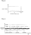
- Fig. 8 is a graph for showing the load torque when the scroll-type compressor is normal.
- Fig. 9 is a graph for showing the vibration detection value in the tangential direction T when the scroll-type compressor is normal.
- Fig. 10 is a graph for showing the vibration detection value in the tangential direction T when the scroll-type compressor is degraded.
- Fig. 11 is a graph for showing a change in feature amount along with the progress of degradation of the compressor.
- the horizontal axis represents the rotation angle [rad]
- the vertical axis represents the load torque.
- the horizontal axis represents time
- the vertical axis represents the vibration detection value.
- an amplitude of the vibrational acceleration detected by the first vibration sensor 12a is shown.
- the horizontal axis represents the number of computations
- the vertical axis represents the feature amount.
- the vibration pattern in the tangential direction T changes, as shown in Fig. 10 . Therefore, when the feature amount is computed with use of the first vibration detection value to digitize a calculation of a vibrational waveform, the compressor 100 has a feature amount with a characteristic of having different values in a normal interval in which the compressor 100 operates normally and a degradation interval in which the compressor 100 operates in a degraded state, as shown in Fig. 11 .
- a median and a standard deviation of a probability density distribution of the feature amount when the compressor 100 is normal and those when the compressor 100 is degraded are different.
- at least one feature amount is selected in accordance with, for example, the type of the compressor 100, specifically, in accordance with a motion pattern of the movable component of the compression mechanism unit 40, and the selected feature amount is computed and analyzed. In this manner, whether the compressor 100 is normal or degraded can be determined.
- a crest value that is computed from the vibration detection value shown in Fig. 9 is 5, and a crest value that is computed from the vibration detection value shown in Fig. 10 falls within a range of from 7 to 8.
- Figs. 12 are explanatory diagrams illustrating schematic cross sections of the compression mechanism unit of the scroll-type compressor. With reference to Figs. 12 , movement of the compression mechanism unit 40 and the sliding portion of the compression mechanism unit 40 when the compressor 100 is the scroll-type compressor are described. As illustrated in Figs. 12 , the compression mechanism unit 40 includes a fixed scroll 41 having a fixed spiral body and an orbiting scroll 42 having an orbiting spiral body.
- the orbiting scroll 42 which is coupled to the rotary shaft, starts rotating and starts compressing a refrigerant gas R in cooperation with the fixed scroll 41.
- the refrigerant gas R sucked from the suction pipe 101a flows into the shell 50 and is sucked into the compression mechanism unit 40 that is formed to include the fixed scroll 41 and the orbiting scroll 42.
- the orbiting scroll 42 performs a turning motion in the order of Fig. 12(b), Fig. 12(c), and Fig. 12(d) under a state in which part of a side surface thereof is held in contract with part of a side surface of the fixed scroll 41.
- the compressed refrigerant gas R is exhausted from a discharge port (not shown) formed in a central portion of the fixed scroll 41 to be discharged outside of the shell 50 via the discharge pipe 100a.
- the orbiting scroll 42 performs the turning motion along with the rotational motion of the rotary shaft.
- a portion at which the fixed scroll 41 and the orbiting scroll 42 are held in contact with each other changes along with the turning motion of the orbiting scroll 42. Therefore, the above-mentioned portion becomes the sliding portion.
- Figs. 13 are explanatory diagrams illustrating schematic cross sections of the compression mechanism unit 40 of the rotary-type compressor. With reference to Figs. 13 , movement of the compression mechanism unit 40 and the sliding portion of the compression mechanism unit 40 when the compressor 100 is the rotary-type compressor are described.
- the compression mechanism unit 40 includes a cylinder 43, a rolling piston 44, a vane 45, a vane spring 46, a suction port 47, and a discharge port 48.
- a compression chamber 43a is formed, which is a cylindrical space having both ends in an axial direction of a rotary shaft 70 being open.
- the rolling piston 44 is provided inside the compression chamber 43a, and is rotated in close contact with an inner wall of the cylinder 43 along with a rotational motion of an eccentric portion of the rotary shaft 70.
- the vane 45 partitions a space formed by an inner wall of the compression chamber 43a and an outer wall of the rolling piston 44.
- the vane spring 46 is provided in a back pressure chamber 46a and is configured to press an end of the vane 45, which is located on a side closer to the compression chamber 43a, against the outer wall of the rolling piston 44.
- the rolling piston 44 is rotated along with the rotational motion of the rotary shaft 70.
- a portion at which the inner wall of the cylinder 43 and the outer wall of the rolling piston 44 are held in contact with each other and a portion at which the end of the vane 45, which is located on the side closer to the compression chamber 43a, and the outer wall of the rolling piston 44 are held in contact with each other are shifted along with the rotation of the rolling piston 44.
- Each of the above-mentioned portions becomes the sliding portion.
- the compressor 100 has a different sliding portion based on the movement of the compression mechanism unit 40 and the rotational motion of the rotary shaft for each type, and the vibration detection value and the feature amount, which are useful for the degradation diagnosis, are also different.
- the vibration detection value in the tangential direction T is more useful for some compressors 100
- the vibration detection value in the circle center direction Co is more useful for other compressors 100. Therefore, for example, when performing the degradation diagnosis for the compressor 100 for which the vibration detection value in the tangential direction T is more useful as in the case of the scroll-type compressor which mainly performs the rotational motion, the vibration detection device 10 may include only the first vibration sensor 12a.
- the vibration detection device 10 may include only the second vibration sensor 12b.
- the vibration detection device 10 may include a single biaxial acceleration sensor, which is configured to detect the vibrational acceleration in the tangential direction T and the vibrational acceleration in the circle center direction Co, in place of the first vibration sensor 12a and the second vibration sensor 12b each being a uniaxial acceleration sensor.
- the mounting of the vibration detection device 10 is not limited thereto.
- the mounting portion 11 may be fixed to the shell 50 by welding.
- the mounting portion 11 may be mounted to the shell 50 with, for example, an adhesive.
- the configuration of fixing the mounting portion 11 to the shell 50 with the magnet is preferred.
- Fig. 4 and Fig. 5 exemplify the case in which the xy cross section of each of the projecting portions 11b has a right triangular shape
- the shape of the xy cross section of each of the projecting portions 11b is not limited thereto.
- the xy cross section of each of the projecting portions 11b may have an acute triangular shape or an obtuse triangular shape.
- Fig. 4 and Fig. 5 exemplify the case in which the two projecting portions 11b are continuously formed through the central portion 11e therebetween, the formation of the two projecting portions 11b is not limited thereto.
- a gap may be present between the two projecting portions 11b.
- each of the two projecting portions 11b may be formed of a plurality of projecting members arranged along the z-axis direction.
- each of the plurality of projecting members may have a triangular prism shape, a pyramid shape, or a conical shape.
- each of the two projecting portions 11b may be formed by a combination of at least two of the triangular prism shaped projecting member, the pyramid shaped projecting member, and the conical projecting member. In this manner, when the two projecting portions 11b are brought into contact with the shell 50 under a state in which a gap is defined between the projecting members, each of the plurality of projecting members is held in linear contact or point contact with the outer wall of the shell 50.
- Fig. 14 is a schematic sectional view illustrating a state in which a vibration detection device of Modification Example 1-1 of Embodiment 1 of the present invention is taken along the xy plane.
- the sensor holding unit 12 may be connected to an entire surface of the base portion 11a, which is located on a side opposite to the projecting portions 11b.
- the sensor holding unit 12 may be formed to have a trapezoidal cross section along the xy plane.
- Fig. 15 is a schematic sectional view illustrating a state in which a vibration detection device of Modification Example 1-2 of Embodiment 1 of the present invention is taken along the xy plane.
- the vibration detection device 10 may be manufactured exclusively for the compressor 100 including the shell 50 having a predetermine curvature.
- each of the distal end portions 11c of the two projecting portions 11b may have a contact surface having a curvature that matches a curvature of the specific shell 50 so that each of the contact surfaces abuts against the shell 50.
- a fixing force of the projecting portions 11b to the shell 50 can be enhanced, and hence the vibration detection device 10 can be more stably fixed to the shell 50.
- each of the two projecting portions 11b may form a curved surface which is curved toward the central portion 11 e.
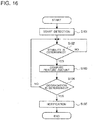
- Fig. 16 is a flowchart illustrating an operation example of the degradation diagnostic device of Fig. 1 .
- Degradation diagnostic processing for the compressor 100 which is performed by the degradation diagnostic device 30, is described with reference to Fig. 16 .
- the degradation diagnosis for the compressor 100 is performed by the degradation diagnostic device 30 with use of both of the vibration detection value detected by the first vibration sensor 12a and the vibration detection value detected by the second vibration sensor 12b.
- Step S101 the detection of the vibrational acceleration in the tangential direction T by the first vibration sensor 12a and the detection of the vibrational acceleration in the circle center direction Co by the second vibration sensor 12b are started (Step S101).
- the stability determining unit 22 acquires the vibrational accelerations respectively detected by the first vibration sensor 12a and the second vibration sensor 12b and determines whether or not the state of the air-conditioning apparatus 200 has become stable based on the acquired vibrational accelerations (Step S102).
- the feature amount computing unit 23 waits until the state of the air-conditioning apparatus 200 becomes stable (Step S102/No). Then, when the stability determining unit 22 determines that the state of the air-conditioning apparatus 200 has become stable (Step S102/Yes), the feature amount computing unit 23 acquires the vibrational accelerations detected by the first vibration sensor 12a and the second vibration sensor 12b. Then, the feature amount indicative of the state of the compressor 100 is computed with use of the acquired vibrational accelerations (Step S103).
- the degradation determining unit 24 determines whether or not the compressor 100 is degraded based on the feature amount computed in the feature amount computing unit 23 (Step S104). When the compressor 100 is not degraded (Step S104/No), the degradation determining unit 24 returns to Step S102 without performing any processing. Meanwhile, when determining that the compressor 100 is degraded (Step S104/Yes), the degradation determining unit 24 outputs information about the degradation to the notification processing unit 25 and the operation switching processing unit 26. The notification processing unit 25 notifies the information about the degradation, which is output from the degradation determining unit 24. Specifically, the notification processing unit 25 executes, for example, display processing for the display unit 400 or transmission processing to the remote monitoring source.
- the operation switching processing unit 26 transmits the life extension operation command to the controller 300. In this manner, the operation switching processing unit 26 switches a control state of the compressor 100 to the life extension operation control (Step S105).
- the sensor holding unit 12 including at least one of the first vibration sensor 12a and the second vibration sensor 12b is formed integrally with the two projecting portions 11b that are arranged on the outer wall of the shell 50 at the position at which the compression mechanism unit 40 is located. Therefore, the vibration caused by, for example, the rotational motion of the compression mechanism unit 40 can be detected by the vibration sensor with high accuracy. Thus, a highly accurate degradation diagnosis for the compressor 100 can be performed. Specifically, with the degradation diagnostic device 30, accuracy of determination of a nondestructive abnormality diagnosis for the sliding portion of the compression mechanism unit 40 can be increased.
- each of the projecting portions 11b has a width in the y-axis direction, which decreases toward the distal end portion 11c, and the distal end portion 11c is held in contact with the shell 50.
- the distal end portion 11c of each of the plurality of projecting portions 11b is formed so as to be held in contact with the outer wall of the shell 50 along the axial direction of the rotary shaft.
- each of the distal end portions 11c of the two projecting portions 11b can be brought into linear contact with the surface of the shell 50, which is formed as the curved surface. Therefore, the vibration detection device 10 can be easily installed so that the longitudinal direction of the mounting portion 11 becomes parallel to the axial direction of the rotary shaft.
- the vibration detection direction of the vibration sensor can be stabilized. Further, the distal end portion 11c of each of the two projecting portions 11b can be brought into contact with and fixed to the compressor 100 including the shell 50 having every curvature along the axial direction of the rotary shaft. Further, the contact portions between the projecting portions 11b and the shell 50 can be reduced. Thus, the intrusion of the dew condensation generated on the surface of the compressor 100 into the vibration sensors can be prevented.
- Each of the two projecting portions 11b includes the magnet, or is formed of the magnet. Therefore, the vibration detection device 10 can be stably fixed over a long time period without reducing the cylindricity of the shell 50.
- the vibration detection device 10 can be easily removed from and mounted onto the shell 50. Thus, under a condition that the vibration detection device 10 is fixed to the shell 50 only at the time of a regular inspection of the compressor 100, convenience can be improved.
- the diagnostic processing device 20 can use the feature amount that is optimal for the vibration pattern based on the motion of the movable component of the compression mechanism unit 40 for the degradation determination for the compressor 100. Thus, the damage of the compressor 100 or other failures can be detected with high accuracy. Further, the diagnostic processing device 20 can detect even a sign of a minor failure of the compressor 100 with high accuracy by finely adjusting the feature amount and the degradation threshold value.
- each of the first vibration sensor 12a and the second vibration sensor 12b of Embodiment 1 is arranged on the outer wall of the shell 50 at the position at which the compression mechanism unit 40 is located so as to match the operating direction of the movable component of the compression mechanism unit 40.
- a highly accurate vibration detection value can be obtained.
- the degradation diagnostic device 30 even when the movable component of the compression mechanism unit 40 is complicated, the damage of the sliding portion of the compression mechanism unit 40 or other failures can be diagnosed with high accuracy.
- Fig. 17 is an external view illustrating a compressor and a vibration detection device of Embodiment 2 of the present invention.
- Fig. 18 is a perspective view illustrating the vibration detection device of Fig. 17 in an enlarged manner.
- a configuration of the vibration detection device of Embodiment 2 is described with reference to Fig. 17 and Fig. 18 .
- Components equivalent to or corresponding to those of Embodiment 1 described above are denoted by the same reference symbols, and description thereof is herein omitted.
- the degradation diagnostic device 30 includes a vibration detection device 110 and the diagnostic processing device 20, and, as in Embodiment 1, is fixed to the compressor 100 of the air-conditioning apparatus 200 as exemplified in Fig. 1 for use.
- the vibration detection device 110 is formed into a band-like shape and is configured to be wound around the shell 50 so as to be fixed thereto. More specifically, a base portion 111a of a mounting portion 111 is formed into an annular shape that surrounds the outer wall of the shell 50.
- the mounting portion 111 has two fastening portions 11f to be fastened with a bolt 13a and a nut 13b. Each of the two fastening portions 11f has a through hole (not shown) that allows the bolt 13a to pass therethrough.
- the mounting portion 111 has five projecting portions 11b.
- One of the mounting portions 111 is arranged so as to be opposed to the two fastening portions 11f, which are in a state of being fastened with the bolt 13a and the nut 13b.
- the projecting portions 11b are respectively formed at positions adjacent to the two fastening portions 11f.
- Two of the mounting portions 111 are arranged so as to be opposed to each other.
- the projecting portion 11b which is arranged so as to be opposed to the two fastening portions 11f, the two projecting portions 11b, which are respectively formed at the positions adjacent to the fastening portions 11f, and the two projecting portions 11b, which are arranged so as to be opposed to each other, are disposed at approximately equal intervals on a curved surface of the base portion 111a, which is located on a side opposite to the sensor holding unit 12. It is apparent that at least one of the five projecting portions 11b may have a rounded smooth shape.
- the sensor holding unit 12 is formed so as to be aligned with one of the plurality of projecting portions 11b in a diametrical direction of the base portion 111a formed into the annular shape.
- the sensor holding unit 12 is aligned with the projecting portion 11b, which is arranged so as to be opposed to the two fastening portions 11f, in the diametrical direction of the base portion 111a.
- the remaining configuration of the vibration detection device 110 is the same as that of the above-mentioned vibration detection device 10 of Embodiment 1.
- the vibration detection device 110 and the diagnostic processing device 20 may be formed integrally.
- the diagnostic processing device 20 may be provided to the base portion 111a or to the sensor holding unit 12.
- the base portion 111a is desired to include a power supply unit, which is configured to supply power to the vibration detection device 110 and the diagnostic processing device 20.
- the degradation diagnostic device 30 may be operated alone.
- the communication processing unit 25b has a wireless communication function
- the diagnostic processing device 20 can wirelessly transmit, for example, the feature amount or the result of degradation determination to the external communication device.
- Fig. 19 is a schematic sectional view illustrating a state in which a vibration detection device of Modification Example 2-1 of Embodiment 2 of the present invention is taken along the xy plane.
- the vibration detection device 110 may have the projecting portions 11b on a large part of the curved surface of the base portion 111a, which is located on the side opposite to the sensor holding unit 12. In this manner, contact portions with the shell 50 increase, and hence the fixing force to the shell 50 can be enhanced.
- each of the plurality of projecting portions 11b may have a rounded shape having, for example, a semicylindrical xy cross section.
- the mounting portion 111 may be formed of a combination of the projecting portions 11b each having a rounded shape and the projecting portions 11b each having a pointed distal end portion.
- Fig. 20 is a schematic sectional view illustrating a state in which a vibration detection device of Modification Example 2-2 of Embodiment 2 of the present invention is taken along the xy plane.
- the vibration detection device 110 has two projecting portions 11b, which are arranged so as to be opposed to each other. A distal end portion of each of the two projecting portions 11b, a portion of the base portion 111a, which is on the periphery of the two fastening portions 11f, and a portion of the base portion 111a, which is on the periphery of the sensor holding unit 12, are configured to be held in contact with the shell 50. Even in this manner, the vibration detection device 110 is stably fixed to the shell 50.
- Fig. 20 exemplifies the configuration in which the sensor holding unit 12 is arranged at the position opposed to the two fastening portions 11f
- the sensor holding unit 12 may be formed so as to be aligned with one of the two projecting portions 11b in the diametrical direction of the base portion 111a. In this manner, the dew condensation generated on the surface of the compressor 100 flows down from a portion of the shell 50, which is not held in contact with the projecting portions 11b. Therefore, the adhesion of the dew condensation to the sensor holding unit 12 can be further prevented.
- the two projecting portions 11b each having a rounded shape are exemplified in Fig. 20 , at least one of the two projecting portions 11b may have a pointed distal end portion.
- Fig. 21 is a schematic sectional view illustrating a state in which a vibration detection device of Modification Example 2-3 of Embodiment 2 of the present invention is taken along the xy plane.
- the mounting portion 111 has the single projecting portion 11b, which has a rounded shape and is arranged so as to be opposed to the two fastening portions 11f.
- the projecting portions 11b each having a pointed distal end portion are formed at positions respectively adjacent to the two fastening portions 11f of the mounting portion 111.
- the single projecting portion 11b which is arranged so as to be opposed to the two fastening portions 11f, may have a pointed distal end portion, whereas each of the projecting portions 11b, which are respectively formed at the positions adjacent to the two fastening portions 11f, may have a rounded distal end portion.
- Fig. 18 to Fig. 21 exemplify the case in which the vibration detection device 110 is fixed to the shell 50 by a fixing unit including the fastening portions 11f, the bolt 13a, and the nut 13b
- the fixing unit is not limited thereto.
- Other general-purpose fixing units can be used as the fixing unit.
- the sensor holding unit 12 including at least one of the first vibration sensor 12a and the second vibration sensor 12b is formed integrally with the two projecting portions 11b that are fixed to the shell 50. Therefore, the vibration caused by, for example, the rotational motion of the compression mechanism unit 40 can be detected by the vibration sensor with high accuracy. Thus, a highly accurate degradation diagnosis for the compressor 100 can be performed.
- the base portion 111a is formed into the annular shape that surrounds the outer wall of the shell 50. Therefore, the vibration detection device 110 can be stably fixed to the shell 50. Further, the sensor holding unit 12 is formed so as to be aligned with one of the plurality of projecting portions 11b in the diametrical direction of the base portion 111 a. Therefore, the vibration transmitted from the compression mechanism unit 40 can be directly detected by the vibration sensors. Thus, the highly accurate vibration detection values can be acquired. Other effects are the same as those of Embodiment 1 described above.
- each of the embodiments described above is a suitable specific example for the degradation diagnostic device and the air-conditioning apparatus, and a technical scope of the present invention is not limited to the above-mentioned modes.
- each of the functions of the diagnostic processing device 20 may be partially or entirely incorporated into the controller 300.
- the air-conditioning apparatus 200 may include two controllers in which the functions of the controller 300 are separately provided in place of the controller 300. In this case, one of the controllers may be provided to the outdoor unit 200A, whereas another of the controllers may be provided to the indoor unit 200B.
- the air-conditioning apparatus 200 may include a remote controller for operation, which is connected to the controller 300 in a wired or wireless manner.
- the display unit 400 may be provided to the remote controller instead of being provided to the indoor unit 200B.
- the pressure reducing device 105 is not limited to the electronic expansion valve and may be any devices having a function of reducing a pressure of the refrigerant, for example, a capillary tube.
- the pressure reducing device 105 may be provided to the indoor unit 200B.
- vibration detection devices 10 and 100 can be applied to compressors for, for example, a refrigerating machine, a freezing display case, a refrigerated display case, and a chiller.
Landscapes
- Engineering & Computer Science (AREA)
- Mechanical Engineering (AREA)
- General Engineering & Computer Science (AREA)
- Physics & Mathematics (AREA)
- General Physics & Mathematics (AREA)
- Control Of Positive-Displacement Pumps (AREA)
- Applications Or Details Of Rotary Compressors (AREA)
- Compressor (AREA)
- Measurement Of Mechanical Vibrations Or Ultrasonic Waves (AREA)
Abstract
Description
- The present invention relates to a degradation diagnostic device, which is configured to diagnose degradation of a compressor, and to an air-conditioning apparatus.
- Hitherto, there has been proposed a technology of predicting an abnormality or a failure which may occur in a constituent device from data indicative of an operating state of an air-conditioning apparatus and applying the predicted abnormality or failure to stabilization of an operation of the air-conditioning apparatus (see, for example,
Patent Literature 1 and Patent Literature 2).Patent Literature 1 discloses a technology of predicting a lifetime of a compressor based on a vibration detection value obtained by an acceleration sensor that is mounted to a leg portion of the compressor. An air-conditioning apparatus disclosed inPatent Literature 2 includes a terminal cover provided on a peripheral surface of a shell of a compressor and stops the compressor when a vibration detection value obtained by an acceleration sensor provided inside the terminal cover indicates an abnormality. -
- Patent Literature 1: Japanese Unexamined Patent Application Publication No.
Hei 10-288379 - Patent Literature 2: Japanese Unexamined Patent Application Publication No.
2011-94920 - However, the leg portion of the compressor is located at a position to which vibration of the compressor caused by, for example, a rotational motion of a compression mechanism unit is unlikely to be transmitted. Further, the terminal cover that covers a power supply connection portion is generally provided at a position to which the vibration of the compressor is unlikely to be transmitted. In addition, the terminal cover has low fixation strength. Thus, for example, noise tends to be mixed with the vibration detection value obtained by the acceleration sensor that is provided inside the terminal cover. Therefore, there is a problem in detection accuracy. Specifically, with the technologies disclosed in
Patent Literature 1 andPatent Literature 2, the vibration caused by, for example, the rotational motion of the compression mechanism unit cannot be detected with high accuracy. Therefore, a problem arises that a degree of degradation of the compressor cannot be precisely diagnosed. - The present invention has been made to solve the problems described above, and an object thereof is to provide a degradation diagnostic device, which is capable of detecting vibration caused by, for example, a rotational motion of a compression mechanism unit with high accuracy to perform a highly accurate degradation diagnosis for a compressor, and an air-conditioning apparatus.
- According to one embodiment of the present invention, there is provided a degradation diagnostic device configured to perform a diagnosis for degradation of a compressor including a compression mechanism unit to be driven along with a rotational motion of a rotary shaft and a shell forming an outer casing, the degradation diagnostic device including a vibration detection device to be fixed onto an outer wall of the shell at a position at which the compression mechanism unit is located, in which the vibration detection device includes: a vibration sensor configured to detect vibration of the compressor; a sensor holding unit including the vibration sensor; a base portion to which the sensor holding unit is connected; and a plurality of projecting portions formed on a surface of the base portion on a side opposite to the sensor holding unit and to be brought into contact with the outer wall.
- According to one embodiment of the present invention, there is provided an air-conditioning apparatus, including: a refrigeration cycle, through which refrigerant circulates, the refrigeration cycle being formed by connecting, by a refrigerant pipe, a compressor, which includes a compression mechanism unit to be driven along with a rotational motion of a rotary shaft and is configured to compress the refrigerant, a heat source-side heat exchanger configured to exchange heat between a heat medium and the refrigerant, a pressure reducing device, which is configured to regulate a flow rate of the refrigerant, and a use-side heat exchanger configured to exchange heat between an indoor air and the refrigerant; and the degradation diagnostic device described above.
- According to one embodiment of the present invention, the sensor holding unit including the vibration sensor is formed integrally with the plurality of projecting portions which are brought into contact with the outer wall of the shell at the position at which the compression mechanism unit is located. Therefore, the vibration caused by, for example, the rotational motion of the compression mechanism unit can be detected by the vibration sensor with high accuracy. Thus, the highly accurate degradation diagnosis for the compressor can be performed.
-
-
Fig. 1 is a configuration diagram of an air-conditioning apparatus and a degradation diagnostic device according toEmbodiment 1 of the present invention. -
Fig. 2 is an external view illustrating a compressor and a vibration detection device ofFig. 1 . -
Fig. 3 is an explanatory view schematically illustrating a cross section of a compression mechanism unit and a shell ofFig. 2 , which is taken along an xy plane. -
Fig. 4 is an enlarged perspective view illustrating the vibration detection device ofFig. 2 . -
Fig. 5 is a schematic sectional view illustrating a state in which the vibration detection device ofFig. 4 is taken along the xy plane. -
Fig. 6 is a block diagram illustrating a functional configuration of a diagnostic processing device ofFig. 1 . -
Fig. 7 is a graph showing a variation rate of a load torque during one revolution for each type of a compressor. -
Fig. 8 is a graph showing the load torque when a scroll-type compressor is normal. -
Fig. 9 is a graph showing a vibration detection value in a tangential direction T when the scroll-type compressor is normal. -
Fig. 10 is a graph showing the vibration detection value in the tangential direction T when the scroll-type compressor is degraded. -
Fig. 11 is a graph showing a change in feature amount along with progress of degradation of the compressor. -
Figs. 12 are explanatory diagrams illustrating schematic cross sections of a compression mechanism unit of the scroll-type compressor. -
Figs. 13 are explanatory diagrams illustrating schematic cross sections of a compression mechanism unit of a rotary-type compressor. -
Fig. 14 is a schematic sectional view illustrating a state in which a vibration detection device of Modification Example 1-1 ofEmbodiment 1 of the present invention is taken along the xy plane. -
Fig. 15 is a schematic sectional view illustrating a state in which a vibration detection device of Modification Example 1-2 ofEmbodiment 1 of the present invention is taken along the xy plane. -
Fig. 16 is a flowchart illustrating an operation example of the degradation diagnostic device ofFig. 1 . -
Fig. 17 is an external view illustrating a compressor and a vibration detection device ofEmbodiment 2 of the present invention. -
Fig. 18 is a perspective view illustrating the vibration detection device ofFig. 17 in an enlarged manner. -
Fig. 19 is a schematic sectional view illustrating a state in which a vibration detection device of Modification Example 2-1 ofEmbodiment 2 of the present invention is taken along the xy plane. -
Fig. 20 is a schematic sectional view illustrating a state in which a vibration detection device of Modification Example 2-2 ofEmbodiment 2 of the present invention is taken along the xy plane. -
Fig. 21 is a schematic sectional view illustrating a state in which a vibration detection device of Modification Example 2-3 ofEmbodiment 2 of the present invention is taken along the xy plane. -
Fig. 1 is a configuration diagram of an air-conditioning apparatus and a degradation diagnostic device according toEmbodiment 1 of the present invention. As illustrated inFig. 1 , an air-conditioning apparatus 200 includes anoutdoor unit 200A, which is installed outdoors, and anindoor unit 200B, which is installed indoors. Theoutdoor unit 200A includes acompressor 100, asuction muffler 101 connected to a suction side of thecompressor 100, and a four-way valve 103 connected to a discharge side of thecompressor 100. Theoutdoor unit 200A includes a heat source-side heat exchanger 104, which is formed of, for example, a fin-and-tube type heat exchanger and is configured to exchange heat between an outdoor air and refrigerant, and apressure reducing device 105, which is formed of, for example, an electric expansion valve and is configured to regulate a flow rate of the refrigerant. Theindoor unit 200B includes a use-side heat exchanger 106, which is formed of, for example, a fin-and-tube type heat exchanger and is configured to exchange heat between an indoor air and the refrigerant. Specifically, the air-conditioning apparatus 200 has a refrigeration cycle through which the refrigerant circulates, which is formed by connecting thecompressor 100, thesuction muffler 101, the four-way valve 103, the heat source-side heat exchanger 104, thepressure reducing device 105, and the use-side heat exchanger 106 by arefrigerant pipe 150. - The
compressor 100 is configured to suck refrigerant in a low-pressure gaseous state and compress the refrigerant into refrigerant in a high-pressure gaseous state. Thecompressor 100 may be one which is capable of appropriately changing an operating frequency by inverter control or may be operated at a constant velocity without a function of changing the operating frequency. As thecompressor 100, various compressors such as a scroll-type compressor, a rotary-type compressor, a reciprocating-type compressor, a helical-type compressor, and a turbo-type compressor can be adopted. The four-way valve 103 is configured to switch flow of the refrigerant from thecompressor 100. The four-way valve 103 is, for example, connected to a side indicated by the solid line ofFig. 1 during a heating operation and is connected to a side indicated by the broken line ofFig. 1 during a cooling operation. - The
outdoor unit 200A includes acontroller 300, which is configured to control the refrigeration cycle. Specifically, thecontroller 300 is configured to control, for example, the operation frequency of thecompressor 100, processing for switching the four-way valve 103, and an opening degree of thepressure reducing device 105. Theoutdoor unit 200A includes a degradationdiagnostic device 30. The degradationdiagnostic device 30 includes avibration detection device 10 and adiagnostic processing device 20. - The
vibration detection device 10 and thediagnostic processing device 20 are connected in a wired or wireless manner. Specifically, thediagnostic processing device 20 is configured to acquire vibration detection values detected by afirst vibration sensor 12a and asecond vibration sensor 12b in a wired or wireless manner from thevibration detection device 10. Theindoor unit 200B includes a display unit 400, which is formed of, for example, a liquid crystal display (LCD). -
Fig. 2 is an external view illustrating the compressor and the vibration detection device ofFig. 1 .Fig. 3 is an explanatory view schematically illustrating a cross section of a compression mechanism unit and a shell ofFig. 2 , which is taken along an xy plane. As illustrated inFig. 2 , thecompressor 100 includes ashell 50 and aleg portion 60. Theshell 50 forms an outer casing of thecompressor 100. Thecompressor 100 includes acompression mechanism unit 40, which is driven along with a rotational motion of a rotary shaft (not shown), inside theshell 50. Thecompression mechanism unit 40 is coupled to an electric motor (not shown) through intermediation of the rotary shaft. The rotary shaft transmits a rotational force of the electric motor to thecompression mechanism unit 40. Adischarge pipe 100a is provided to thecompressor 100, whereas asuction pipe 101a is provided to thesuction muffler 101. - The
compression mechanism unit 40 is vibrated by a rotational motion or a reciprocating motion of an internal movable component, and the vibration thereof is transmitted to theshell 50. The vibration of thecompression mechanism unit 40 is more intensely transmitted to a portion of theshell 50, which is positioned on an outer periphery of thecompression mechanism unit 40. Thecompression mechanism unit 40 repeats a predetermined motion pattern in a given cycle. Therefore, a vibration pattern generated due to the motion of the movable component of thecompression mechanism unit 40 is transmitted to theshell 50. Thus, thevibration detection device 10 is fixed to an outer wall of theshell 50 at a position at which thecompression mechanism unit 40 is located, as illustrated inFig. 2 . - The
vibration detection device 10 includes asensor holding unit 12, which includes thefirst vibration sensor 12a, thesecond vibration sensor 12b, and a holdingmember 12c. Specifically, thesensor holding unit 12 includes thefirst vibration sensor 12a and thesecond vibration sensor 12b, which are provided to the holdingmember 12c. Thevibration detection device 10 includes a mountingportion 11, which is connected to thesensor holding unit 12. The mountingportion 11 is located on a side close to thecompressor 100 with respect to thesensor holding unit 12 under a state in which thevibration detection device 10 is fixed to thecompressor 100. - The
first vibration sensor 12a and thesecond vibration sensor 12b are arranged so that a vibration detection direction matches a direction of the motion of the movable component of thecompression mechanism unit 40. The direction of the motion of the movable component of thecompression mechanism unit 40 includes a tangential direction T, which is a direction of a tangent of a rotation trajectory of thecompression mechanism unit 40, and a circle center direction Co, which is a direction from the outer wall of theshell 50 toward a center of thecompression mechanism unit 40. Thefirst vibration sensor 12a is arranged so that the vibration detection direction matches the tangential direction T. Thesecond vibration sensor 12b is arranged so that the vibration detection direction matches the circle center direction Co. Specifically, thefirst vibration sensor 12a detects vibration along the tangential direction T of thecompressor 100, which is caused by the rotational motion of the movable component of thecompression mechanism unit 40, as a first vibration detection value. Thesecond vibration sensor 12b detects vibration along the circle center direction Co of thecompressor 100, which is caused by the reciprocating motion of the movable component of thecompression mechanism unit 40, as a second vibration detection value. - In
Fig. 2 , the tangential direction T is parallel to an x-axis direction, the circle center direction Co is parallel to a y-axis direction, and an axial direction of the rotary shaft corresponds to a z-axis direction. The same applies to the drawings referred to below. As illustrated inFig. 3 , the tangential direction T is a direction orthogonal to a diametrical direction of theshell 50 on an xy cross section, whereas the circle center direction Co corresponds to the diametrical direction of theshell 50 on the xy cross section. - The
first vibration sensor 12a and thesecond vibration sensor 12b are semiconductor-type micro electro mechanical system (MEMS) sensors, which are included in acceleration sensors configured to detect a vibrational acceleration. In particular, inEmbodiment 1, capacitive type or piezoresistive type MEMS sensors are used as thefirst vibration sensor 12a and thesecond vibration sensor 12b in view of a degree of increase in surface temperature of theshell 50. -
Fig. 4 is an enlarged perspective view illustrating thevibration detection device 10 ofFig. 2 .Fig. 5 is a schematic sectional view illustrating a state in which thevibration detection device 10 ofFig. 4 is taken along the xy plane. A specific structure of thevibration detection device 10 is described with reference toFig. 4 and Fig. 5 . The holdingmember 12c is formed into a cuboidal shape of which the z-axis direction is the longitudinal direction. The mountingportion 11 includes abase portion 11a connected to the holdingmember 12c and two projectingportions 11b provided on a surface of thebase portion 11a, which is located on a side opposite to the holdingmember 12c. - In an example of
Fig. 4 and Fig. 5 , a central portion of thebase portion 11a in the y-axis direction is connected to the holdingmember 12c. Specifically, thebase portion 11a is formed into a cuboidal shape of which the z-axis direction is the longitudinal direction and the length in the y-axis direction is larger than that of the holdingmember 12c. Each of the projectingportions 11b has aninner wall 11d, which is located on a side opposite to thesensor holding unit 12. The two projectingportions 11b form, with the respectiveinner walls 11d, a V-shaped outer wall on the xy cross section. Specifically, each of the projectingportions 11b is formed into a triangular prism shape of which the z-axis direction is a longitudinal direction. In the example ofFig. 4 and Fig. 5 , the projectingportion 11b has a right triangular xy cross section having theinner wall 11d as a hypotenuse. - A magnet, which fixes the
vibration detection device 10 to theshell 50, is embedded in the mountingportion 11. For example, when a weight of thevibration detection device 10 is in a range of from 2 g to 10 g, a magnet having a magnetic force ranging from about 11 N to about 53 N is only required to be used. In this manner, thevibration detection device 10 can be fixed to thecompressor 100 under a state in whichdistal end portions 11c are held in contact with the outer wall of theshell 50. - A magnet may be embedded partly, not entirely, in the mounting
portion 11 as long as the magnetic force sufficient for stably fixing thevibration detection device 10 to theshell 50 can be obtained. For example, a magnet may be provided in each of the two projectingportions 11b. As the magnet, a sheet-shaped magnet or a rod-shaped magnet may be adopted. In this case, it is preferred that the magnet be embedded in a main body of the mountingportion 11 so that a longitudinal direction of the magnet matches a longitudinal direction of the mountingportion 11. - In recent year, an acceleration sensor, which has a high heat resistance, high detection accuracy, and a small size, and is inexpensive as compared to those in the related art, has been developed. Accordingly, the
vibration detection device 10, which is lightweight as in the example described above, can be formed. Thus, thevibration detection device 10 can be easily fixed onto the outer wall of theshell 50 at the position at which thecompression mechanism unit 40 is located for use. - The main body of the mounting
portion 11 and the holdingmember 12c are made of engineering plastic or fiber-reinforced plastic, which is excellent in performance such as a mechanical strength, a heat resistance, and a wear resistance as compared to those of commodity plastics. The low-pressureshell type compressor 100 has a lower surface temperature than a surface temperature of the high-pressureshell type compressor 100. Therefore, when thevibration detection device 10 is mounted to the low-pressureshell type compressor 100, the main body of the mountingportion 11 and the holdingmember 12c can be made of plastic having a relatively low heat resistance. It is apparent that the mountingportion 11 and the holdingmember 12c may be made of different materials. For example, the mountingportion 11 may be formed entirely of a magnet. Alternatively, each of the two projectingportions 11b of the mountingportion 11 may be formed of a magnet. - In
Embodiment 1, a central angle θ, which is an angle formed between theinner walls 11d of the two projectingportions 11b, is set based on curvatures of theshells 50 of various types of thecompressors 100. More specifically, when a center of theshell 50 is a center O for thecompressors 100 having various sizes, to which thevibration detection device 10 is supposed to be fixed, the central angle θ is set so that a distance between the center O and each of thedistal end portions 11c becomes equal to or smaller than a distance between the center O and acentral portion 11 e. - In
Fig. 5 , an outer wall S, an outer wall M, and an outer wall L are exemplified as the outer walls of theshells 50, which have different curvatures, specifically, different diameters. The diameters of theshells 50 increase in the order of the outer wall S, the outer wall M, and the outer wall L. As illustrated inFig. 5 , both of thedistal end portions 11c of the two projectingportions 11b are held in contact with each of the outer wall S, the outer wall M, and the outer wall L. Specifically, under a state in which thevibration detection device 10 is fixed to thecompressor 100, thedistal end portions 11c of the two projectingportions 11b are held in contact with the outer wall of theshell 50 of every diameter. Therefore, thevibration detection device 10 can be mounted tovarious compressors 100 having different sizes for use. - Further, the
distal end portion 11c of each of the projectingportions 11b has a pointed shape. Specifically, thedistal end portion 11c is formed so as to be held in linear contact with theshell 50 along the axial direction of the rotary shaft under a state in which the mountingportion 11 is fixed to theshell 50. Therefore, dew condensation generated on a surface of thecompressor 100 flows from a portion in which the projectingportions 11b are not held in contact with theshell 50. Therefore, adhesion of the dew condensation to thefirst vibration sensor 12a and thesecond vibration sensor 12b can be prevented. Specifically, thevibration detection device 10 is fixed to thecompressor 100 under a state in which thedistal end portions 11c located at the distal ends of the mountingportion 11 are held in contact with theshell 50. Therefore, in particular, in a case where thefirst vibration sensor 12a and thesecond vibration sensor 12b are connected to thediagnostic processing device 20 through a communication line or other measures, a failure of thefirst vibration sensor 12a and thesecond vibration sensor 12b or other defects due to intrusion of the dew condensation can be prevented. In this case, thedistal end portions 11c may be formed smoothly and rounded. Even with such a shape, the mountingportion 11 of thevibration detection device 10 can be fixed to theshell 50 under a state in which thedistal end portions 11c are held in linear contact with theshell 50 along the axial direction of the rotary shaft. Therefore, the adhesion of the dew condensation to thefirst vibration sensor 12a and thesecond vibration sensor 12b can be prevented. - Further, each of the
first vibration sensor 12a and thesecond vibration sensor 12b is provided so that the vibration detection direction is at a right angle relative to thedistal end portions 11c formed along the axial direction of the rotary shaft. Therefore, through the contact of thedistal end portions 11c with theshell 50 along the axial direction of the rotary shaft, thefirst vibration sensor 12a can detect the vibration along the tangential direction T and thesecond vibration sensor 12b can detect the vibration along the circle center direction Co. -
Fig. 6 is a block diagram illustrating a functional configuration of thediagnostic processing device 20 ofFig. 1 . As illustrated inFig. 6 , thediagnostic processing device 20 includes astorage unit 21, a stability determining unit 22, a featureamount computing unit 23, adegradation determining unit 24, anotification processing unit 25, and an operation switchingprocessing unit 26. In thestorage unit 21, an operation program and various control parameters for thediagnostic processing device 20 and other data are stored. In thestorage unit 21, for example, one or a plurality of degradation threshold values each serving as a standard of degradation determination of thecompressor 100 by thedegradation determining unit 24 are stored. - The stability determining unit 22 is configured to determine whether or not a state of the air-
conditioning apparatus 200 has been stabilized. For example, the stability determining unit 22 may determine whether or not the state of the air-conditioning apparatus 200 has been stabilized by determining whether or not a rotation speed of thecompressor 100 has become constant. Alternatively, the stability determining unit 22 may determine whether or not the state of the air-conditioning apparatus 200 has been stabilized by determining whether or not a state of the refrigeration cycle has been maintained in the same state for a preset time period or longer. In this case, the state of the refrigeration cycle includes a state such as a temperature and a pressure of the refrigerant circulating through the refrigeration cycle. The preset time period is set to, for example, three minutes. The stability determining unit 22 may determine stability of the state of the air-conditioning apparatus 200 with use of at least one of the first vibration detection value and the second vibration detection value. - The feature
amount computing unit 23 is configured to compute a feature amount indicative of the state of thecompressor 100 with use of at least one of the first vibration detection value detected by thefirst vibration sensor 12a and the second vibration detection value detected by thesecond vibration sensor 12b. The featureamount computing unit 23 has a function of computing a plurality of different feature amounts at the same timing. The featureamount computing unit 23 can compute, for example, a standard deviation, a median, an average value, a peak value, an impact index, a form factor, a peak-to-rms ratio, a skewness, a kurtosis, an extreme value of the skewness, an extreme value of the kurtosis, an extreme value of the average value, an average frequency, a crossover frequency, or an extreme value frequency as the feature amount. When obtaining the extreme value of the skewness, the extreme value of the kurtosis, or the extreme value of the average value as the feature amount, the featureamount computing unit 23 uses a maximum value or a minimum value as the extreme value. The featureamount computing unit 23 can compute a level of a rotational load of thecompressor 100, a level of a frequency of a result of FFT analysis of the vibration detection value in the tangential direction T, or other levels as the feature amount. A feature of the vibration in the tangential direction T appears in the feature amount that is computed based on the first vibration detection value, and a feature of the vibration in the circle center direction Co appears in the feature amount that is computed based on the second vibration detection value. The featureamount computing unit 23 has a function of outputting the computed feature amount to thedegradation determining unit 24. - The
degradation determining unit 24 determines a kind of degradation and a degree of degradation of thecompressor 100 based on the feature amount that is computed in the featureamount computing unit 23. When the plurality of different feature amounts are input at the same timing from the featureamount computing unit 23, thedegradation determining unit 24 has a function of determining the degradation with use of the feature amounts in combination. Thedegradation determining unit 24 may determine the degradation of thecompressor 100 with use of data indicative of, for example, the operating state of thecompressor 100 together with the feature amounts. - The degradation threshold value to be used by the
degradation determining unit 24 for the degradation determination may be calculated from, for example, data obtained by a learning operation that is performed to acquire one or a plurality of values of feature amounts for each preset rotation speed of thecompressor 100 in an initial period of the operation of the air-conditioning apparatus 200. Alternatively, the degradation threshold value may be obtained from the value of the feature amount obtained for a given time period by performing a normal operation over the given time period. Further, after a condensing temperature, an evaporating temperature, and the rotation speed of thecompressor 100 are preset, the vibration may be detected for thecompressor 100 alone so as to obtain the degradation threshold value from a result of the detection of vibration. Then, through comparison of the obtained degradation threshold value and mapped values with each other, the degradation threshold values under various conditions may be set. - A kind of degradation and a degree of degradation concerning the degradation determination by the
degradation determining unit 24 are now specifically exemplified. As kinds of degradation of thecompressor 100 to be determined by thedegradation determining unit 24, there are exemplified liquid backflow in thecompressor 100 and damage of a sliding portion of thecompression mechanism unit 40. For example, when the level of the rotational load of thecompressor 100 linearly increases or suddenly rises with elapse of time, it is considered that the sliding portion of thecompression mechanism unit 40 may be damaged to increase a frictional resistance. Specifically, thedegradation determining unit 24 can perform a determination about a degree of damage of the sliding portion based on a variation of the level of the rotational load of thecompressor 100 with time. - Whether or not the sliding portion is damaged can also be determined by detecting an increase in input to the
compressor 100 or a decrease in cooling capacity or heating capacity. However, a state in which the sliding portion is damaged to such a degree that the input to thecompressor 100 increases or the cooling capacity or other capacities decrease corresponds to a state, for example, immediately before stop of the functions of thecompressor 100. Specifically, when thecompressor 100 is operated until the above-mentioned state is brought about, it undesirably becomes difficult or impossible to repair thecompressor 100. - Meanwhile, the degradation
diagnostic device 30 according toEmbodiment 1 performs the degradation diagnosis with use of the feature amount that is computed based on the vibration detection value detected by the vibration sensor. Therefore, when, for example, the level of the rotational load of thecompressor 100 varies in a cycle of several revolutions, it can be estimated that sucked refrigerant in thecompressor 100 is flowing backward. When the level of the rotational load of thecompressor 100 exceeds the degradation threshold value, the degradationdiagnostic device 30 can determine through thedegradation determining unit 24 that the sliding portion of thecompression mechanism unit 40 is damaged. Specifically, with the degradationdiagnostic device 30, a sign of the failure can be detected with high accuracy with use of a variation in feature amount with time. Therefore, such a situation that it may become difficult to repair thecompressor 100 can be prevented. - The following method is also conceivable as a method of determining whether or not the liquid backflow has occurred. Specifically, for example, the following method can be adopted. A ratio of an average of peak values for ten revolutions of the
compressor 100 and a maximum value during the ten revolutions of thecompressor 100 is stored. When the ratio becomes larger than a ratio serving as a reference, it is determined that the sucked refrigerant in thecompressor 100 is flowing backward. - When a level of a frequency of an n-th order or a level of a frequency of an order other than the n-th order of a result of fast Fourier transform (FFT) analysis of the vibration of the
compressor 100 in the tangential direction T increases as compared to the degradation threshold value, it is considered that an abnormality of such a degree that affects the variation in torque during one revolution of thecompressor 100 has occurred in the sliding portion. In particular, when microflaws are generated at a plurality of positions on the sliding portion of thecompression mechanism unit 40, the frictional resistance due to the plurality of microflaws is generated for a plurality of times during one revolution of the sliding portion. Therefore, when there is a difference from a normal value at a frequency component that is higher than the frequency of thecompressor 100, it is considered that the microflaws are generated on the sliding portion. Therefore, when a difference from the normal value becomes larger than a given amount at the frequency component that is higher than the frequency of thecompressor 100, thedegradation determining unit 24 is only required to determine that the microflaws are generated on the sliding portion. - In addition, when an impact component is mixed into the vibration detection value, for example, a value of the peak-to-rms ratio increases. Therefore, when the value of the peak-to-rms ratio becomes larger than a given value, it is considered that lubrication at the sliding portion of the
compression mechanism unit 40 becomes insufficient, resulting in damage of the sliding portion. Therefore, for example, the peak-to-rms ratio may be computed by the featureamount computing unit 23 as the feature amount from a vibrational acceleration in the tangential direction T and a vibrational acceleration in the circle center direction Co so that, when the peak-to-rms ratio computed in the featureamount computing unit 23 exceeds the degradation threshold value, thedegradation determining unit 24 determines that the sliding portion is damaged. - The
notification processing unit 25 is configured to externally notify a result of determination performed by thedegradation determining unit 24. In an example ofFig. 6 , thenotification processing unit 25 includes adisplay processing unit 25a and acommunication processing unit 25b. Thedisplay processing unit 25a is configured to display information indicative of the result of determination performed by thedegradation determining unit 24 on the display unit 400. Thecommunication processing unit 25b is configured to communicate with a communication device (not shown) such as a computer provided to a remote monitoring destination in a wired or wireless manner. As the remote monitoring destination, for example, a monitoring center, which is configured to monitor and control the operating state of the air-conditioning apparatus 200, is assumed. Thecommunication processing unit 25b has a function of transmitting the information indicative of the result of determination performed by thedegradation determining unit 24 to the communication device provided to the remote monitoring source. - The operation switching
processing unit 26 switches a control state of thecompressor 100 from normal operation control to life extension operation control when the degree of degradation of thecompressor 100 exceeds a given reference. Specifically, the operation switchingprocessing unit 26 transmits a life extension operation command to thecontroller 300 in accordance with the result of determination performed by thedegradation determining unit 24, specifically, in accordance with the degree of degradation of thecompressor 100. The life extension operation command is a signal indicative of a reduction amount in operating frequency of thecompressor 100, and includes not only a signal for an instruction about an eighty-percent decrease in operating frequency of thecompressor 100 but also a signal for an instruction about stop of thecompressor 100. The reduction amount in operating frequency of thecompressor 100 is preset in accordance with the kind of degradation and the degree of degradation of thecompressor 100. For example, a reduction-amount table in which the degree of degradation of thecompressor 100 and the reduction amount in operating frequency are associated with each other may be stored in thestorage unit 21 so that the operation switchingprocessing unit 26 generates the life extension operation command with reference to the reduction-amount table. It is preferred that the reduction-amount table be set so that the reduction amount in operating frequency increases as the degradation of thecompressor 100 proceeds. - The
controller 300 has a function of decreasing the operating frequency of thecompressor 100 or stopping thecompressor 100 in accordance with the life extension operation command transmitted from the operation switchingprocessing unit 26. It is apparent that the operation switchingprocessing unit 26 may have a function of controlling thecompressor 100. The operation switchingprocessing unit 26 may decrease the operating frequency of thecompressor 100 or stop thecompressor 100 in accordance with the result of determination performed by thedegradation determining unit 24. - The
indoor unit 200B includes a speaker and may include an output unit configured to output a sound or a voice. Thedisplay processing unit 25a may include an output processing unit, which transmits information indicative of occurrence of damage to the output unit when the degradation of thecompressor 100 is serious and it is determined in thedegradation determining unit 24 that the damage has occurred in thecompressor 100. Then, the output unit may output a sound or a voice based on the information indicative of the occurrence of damage, which has been transmitted from the output processing unit. In this case, thenotification processing unit 25 may include at least one of thedisplay processing unit 25a, thecommunication processing unit 25b, and the output processing unit. - The
diagnostic processing device 20 may be configured without thedegradation determining unit 24 so that, for example, thecommunication processing unit 25b transmits the feature amount computed in the featureamount computing unit 23 to the external communication device. In this manner, the degradation of thecompressor 100 can be diagnosed at the remote monitoring source or other locations with use of the feature amount transmitted from thediagnostic processing device 20. Thediagnostic processing device 20 may also be configured without the featureamount computing unit 23 and thedegradation determining unit 24 so that, for example, thecommunication processing unit 25b transmits the feature amount computed from the vibration detection value detected in thevibration detection device 10 to the external communication device. In this manner, the feature amount can be computed based on the vibration detection value transmitted from thediagnostic processing device 20 at the remote monitoring source or other locations so that the degradation of thecompressor 100 is diagnosed with use of the computed feature amount. Further, thediagnostic processing device 20 may be configured without the operation switchingprocessing unit 26. - The
vibration detection device 10 and thediagnostic processing device 20 may be formed integrally. Specifically, thediagnostic processing device 20 may be provided to thebase portion 11a or to thesensor holding unit 12. Thebase portion 11a is desired to include a power supply unit, which is configured to supply power to thevibration detection device 10 and thediagnostic processing device 20. In this manner, the degradationdiagnostic device 30 may be operated alone. When thecommunication processing unit 25b has a wireless communication function, thediagnostic processing device 20 may wirelessly transmit information such as the feature amount or the result of degradation determination to the external communication device. - The
diagnostic processing device 20 can be achieved with hardware such as a circuit device which achieves each of the functions described above or can be achieved as software to be executed on a computing device such as a microcomputer, a digital signal processor (DSP), or a central processing unit (CPU). Thestorage unit 21 may be formed of, for example, a random access memory (RAM) and a read only memory (ROM), a programmable ROM (PROM) such as a flash memory, or a hard disk drive (HDD). -
Fig. 7 is a graph for showing a variation rate of a load torque during one revolution for each type of the compressor. InFig. 7 , the horizontal axis represents a rotation angle [rad], whereas the vertical axis represents the variation rate of the load torque. In this manner, variations of the load torques of thecompressors 100 of the respective types are compared to each other. InFig. 7 , a line graph A shows a characteristic of a scroll-type compressor, a line graph B shows a characteristic of a single rotary-type compressor, and a line graph C shows a characteristic of a twin rotary-type compressor. A line graph D shows a characteristic of a reciprocating-type compressor, and a line graph E shows a characteristic of a helical-type compressor. In this manner, thecompressor 100 has a feature in a load torque pattern during one revolution in accordance with each of the types. -
Fig. 8 is a graph for showing the load torque when the scroll-type compressor is normal.Fig. 9 is a graph for showing the vibration detection value in the tangential direction T when the scroll-type compressor is normal.Fig. 10 is a graph for showing the vibration detection value in the tangential direction T when the scroll-type compressor is degraded.Fig. 11 is a graph for showing a change in feature amount along with the progress of degradation of the compressor. InFig. 8 , the horizontal axis represents the rotation angle [rad], whereas the vertical axis represents the load torque. InFig. 9 andFig. 10 , the horizontal axis represents time, whereas the vertical axis represents the vibration detection value. Specifically, inFig. 9 andFig. 10 , an amplitude of the vibrational acceleration detected by thefirst vibration sensor 12a is shown. InFig. 11 , the horizontal axis represents the number of computations, whereas the vertical axis represents the feature amount. - An influence of the
compression mechanism unit 40 which performs the rotational motion or other motions greatly appears in the load torque pattern during one revolution. Therefore, as is understood fromFig. 8 and Fig. 9 , the vibration of thecompressor 100 in the tangential direction T and the load torque pattern have a high correlation. - For example, when oil at the sliding portion of the
compression mechanism unit 40 is depleted to damage the sliding portion due to a decrease in oil return amount to thecompressor 100, which is caused by the liquid backflow or oil loss through a piston cylinder, the vibration pattern in the tangential direction T changes, as shown inFig. 10 . Therefore, when the feature amount is computed with use of the first vibration detection value to digitize a calculation of a vibrational waveform, thecompressor 100 has a feature amount with a characteristic of having different values in a normal interval in which thecompressor 100 operates normally and a degradation interval in which thecompressor 100 operates in a degraded state, as shown inFig. 11 . A median and a standard deviation of a probability density distribution of the feature amount when thecompressor 100 is normal and those when thecompressor 100 is degraded are different. Specifically, at least one feature amount is selected in accordance with, for example, the type of thecompressor 100, specifically, in accordance with a motion pattern of the movable component of thecompression mechanism unit 40, and the selected feature amount is computed and analyzed. In this manner, whether thecompressor 100 is normal or degraded can be determined. A crest value that is computed from the vibration detection value shown inFig. 9 is 5, and a crest value that is computed from the vibration detection value shown inFig. 10 falls within a range of from 7 to 8. - For the sliding portion of the
compression mechanism unit 40 described above, configuration examples in the cases of the scroll-type compressor and the rotary-type compressor are now described with reference toFig. 12 andFig. 13 . -
Figs. 12 are explanatory diagrams illustrating schematic cross sections of the compression mechanism unit of the scroll-type compressor. With reference toFigs. 12 , movement of thecompression mechanism unit 40 and the sliding portion of thecompression mechanism unit 40 when thecompressor 100 is the scroll-type compressor are described. As illustrated inFigs. 12 , thecompression mechanism unit 40 includes a fixedscroll 41 having a fixed spiral body and anorbiting scroll 42 having an orbiting spiral body. - When the rotary shaft (not shown) of the
compressor 100 is rotated, the orbitingscroll 42, which is coupled to the rotary shaft, starts rotating and starts compressing a refrigerant gas R in cooperation with the fixedscroll 41. Specifically, as illustrated inFig. 12(a) , the refrigerant gas R sucked from thesuction pipe 101a flows into theshell 50 and is sucked into thecompression mechanism unit 40 that is formed to include the fixedscroll 41 and the orbitingscroll 42. Subsequently, the orbitingscroll 42 performs a turning motion in the order ofFig. 12(b), Fig. 12(c), and Fig. 12(d) under a state in which part of a side surface thereof is held in contract with part of a side surface of the fixedscroll 41. In this manner, the compressed refrigerant gas R is exhausted from a discharge port (not shown) formed in a central portion of the fixedscroll 41 to be discharged outside of theshell 50 via thedischarge pipe 100a. - As described above, in the
compression mechanism unit 40 of the scroll-type compressor, the orbitingscroll 42 performs the turning motion along with the rotational motion of the rotary shaft. A portion at which the fixedscroll 41 and the orbitingscroll 42 are held in contact with each other changes along with the turning motion of the orbitingscroll 42. Therefore, the above-mentioned portion becomes the sliding portion. -
Figs. 13 are explanatory diagrams illustrating schematic cross sections of thecompression mechanism unit 40 of the rotary-type compressor. With reference toFigs. 13 , movement of thecompression mechanism unit 40 and the sliding portion of thecompression mechanism unit 40 when thecompressor 100 is the rotary-type compressor are described. - As illustrated in
Figs. 13 , thecompression mechanism unit 40 includes acylinder 43, a rollingpiston 44, avane 45, avane spring 46, asuction port 47, and adischarge port 48. Inside thecylinder 43, acompression chamber 43a is formed, which is a cylindrical space having both ends in an axial direction of arotary shaft 70 being open. The rollingpiston 44 is provided inside thecompression chamber 43a, and is rotated in close contact with an inner wall of thecylinder 43 along with a rotational motion of an eccentric portion of therotary shaft 70. Thevane 45 partitions a space formed by an inner wall of thecompression chamber 43a and an outer wall of the rollingpiston 44. Thevane spring 46 is provided in aback pressure chamber 46a and is configured to press an end of thevane 45, which is located on a side closer to thecompression chamber 43a, against the outer wall of the rollingpiston 44. - In the
compression mechanism unit 40, when the refrigerant gas R in theshell 50 flows into theback pressure chamber 46a via thesuction port 47 as illustrated inFig. 13(a) , a pressure difference is generated between a pressure of the refrigerant gas R in theback pressure chamber 46a and a pressure of the refrigerant gas R in thecompression chamber 43a. Thevane 45 is moved toward a center of thecompression chamber 43a by the pressure difference, and hence the end of thevane 45, which is located on the side close to thecompression chamber 43a, abuts against the cylindrical outer wall of the rollingpiston 44. Then, the rollingpiston 44 is rotated in the order ofFig. 13(b), Fig. 13(c), and Fig. 13(d) under a state in which part of the outer wall thereof is held in contact with part of the inner wall of thecylinder 43 along with the rotational motion of therotary shaft 70. In this manner, the compressed refrigerant gas R is exhausted from thedischarge port 48 of thecompression chamber 43a to be discharged outside of theshell 50 via thedischarge pipe 100a. - As described above, in the
compression mechanism unit 40 of the rotary-type compressor, the rollingpiston 44 is rotated along with the rotational motion of therotary shaft 70. A portion at which the inner wall of thecylinder 43 and the outer wall of the rollingpiston 44 are held in contact with each other and a portion at which the end of thevane 45, which is located on the side closer to thecompression chamber 43a, and the outer wall of the rollingpiston 44 are held in contact with each other are shifted along with the rotation of the rollingpiston 44. Each of the above-mentioned portions becomes the sliding portion. - As in the example described above, the
compressor 100 has a different sliding portion based on the movement of thecompression mechanism unit 40 and the rotational motion of the rotary shaft for each type, and the vibration detection value and the feature amount, which are useful for the degradation diagnosis, are also different. Specifically, for the degradation diagnosis, the vibration detection value in the tangential direction T is more useful for somecompressors 100, and the vibration detection value in the circle center direction Co is more useful forother compressors 100. Therefore, for example, when performing the degradation diagnosis for thecompressor 100 for which the vibration detection value in the tangential direction T is more useful as in the case of the scroll-type compressor which mainly performs the rotational motion, thevibration detection device 10 may include only thefirst vibration sensor 12a. Meanwhile, when performing the degradation diagnosis for thecompressor 100 for which the vibration detection value in the tangential direction T is more useful, thevibration detection device 10 may include only thesecond vibration sensor 12b. Thevibration detection device 10 may include a single biaxial acceleration sensor, which is configured to detect the vibrational acceleration in the tangential direction T and the vibrational acceleration in the circle center direction Co, in place of thefirst vibration sensor 12a and thesecond vibration sensor 12b each being a uniaxial acceleration sensor. - Although the
vibration detection device 10, which is mounted to theshell 50 with the magnetic force of the magnet provided in the mountingportion 11, has been exemplified above, the mounting of thevibration detection device 10 is not limited thereto. For example, the mountingportion 11 may be fixed to theshell 50 by welding. The mountingportion 11 may be mounted to theshell 50 with, for example, an adhesive. In view of, for example, a decrease in cylindricity of theshell 50 due to the welding and durability of the adhesive, the configuration of fixing the mountingportion 11 to theshell 50 with the magnet is preferred. - Although
Fig. 4 and Fig. 5 exemplify the case in which the xy cross section of each of the projectingportions 11b has a right triangular shape, the shape of the xy cross section of each of the projectingportions 11b is not limited thereto. The xy cross section of each of the projectingportions 11b may have an acute triangular shape or an obtuse triangular shape. Further, althoughFig. 4 and Fig. 5 exemplify the case in which the two projectingportions 11b are continuously formed through thecentral portion 11e therebetween, the formation of the two projectingportions 11b is not limited thereto. A gap may be present between the two projectingportions 11b. - Further, each of the two projecting
portions 11b may be formed of a plurality of projecting members arranged along the z-axis direction. For example, each of the plurality of projecting members may have a triangular prism shape, a pyramid shape, or a conical shape. In addition, each of the two projectingportions 11b may be formed by a combination of at least two of the triangular prism shaped projecting member, the pyramid shaped projecting member, and the conical projecting member. In this manner, when the two projectingportions 11b are brought into contact with theshell 50 under a state in which a gap is defined between the projecting members, each of the plurality of projecting members is held in linear contact or point contact with the outer wall of theshell 50. Specifically, a portion, which is not held in contact with the outer wall of theshell 50, is present on each of the projecting members, and dew condensation generated on the surface of thecompressor 100 flows from the above-mentioned portion. Therefore, the adhesion of dew condensation to thefirst vibration sensor 12a and thesecond vibration sensor 12b can be more reliably prevented. -
Fig. 14 is a schematic sectional view illustrating a state in which a vibration detection device of Modification Example 1-1 ofEmbodiment 1 of the present invention is taken along the xy plane. As illustrated inFig. 14 , thesensor holding unit 12 may be connected to an entire surface of thebase portion 11a, which is located on a side opposite to the projectingportions 11b. Thesensor holding unit 12 may be formed to have a trapezoidal cross section along the xy plane. -
Fig. 15 is a schematic sectional view illustrating a state in which a vibration detection device of Modification Example 1-2 ofEmbodiment 1 of the present invention is taken along the xy plane. As illustrated inFig. 15 , thevibration detection device 10 may be manufactured exclusively for thecompressor 100 including theshell 50 having a predetermine curvature. Specifically, each of thedistal end portions 11c of the two projectingportions 11b may have a contact surface having a curvature that matches a curvature of thespecific shell 50 so that each of the contact surfaces abuts against theshell 50. In this manner, a fixing force of the projectingportions 11b to theshell 50 can be enhanced, and hence thevibration detection device 10 can be more stably fixed to theshell 50. Further, with theinner wall 11d of each of the two projectingportions 11b, each of the two projectingportions 11b may form a curved surface which is curved toward thecentral portion 11 e. -
Fig. 16 is a flowchart illustrating an operation example of the degradation diagnostic device ofFig. 1 . Degradation diagnostic processing for thecompressor 100, which is performed by the degradationdiagnostic device 30, is described with reference toFig. 16 . In this case, there is described an operation example in which the degradation diagnosis for thecompressor 100 is performed by the degradationdiagnostic device 30 with use of both of the vibration detection value detected by thefirst vibration sensor 12a and the vibration detection value detected by thesecond vibration sensor 12b. - First, the detection of the vibrational acceleration in the tangential direction T by the
first vibration sensor 12a and the detection of the vibrational acceleration in the circle center direction Co by thesecond vibration sensor 12b are started (Step S101). Then, the stability determining unit 22 acquires the vibrational accelerations respectively detected by thefirst vibration sensor 12a and thesecond vibration sensor 12b and determines whether or not the state of the air-conditioning apparatus 200 has become stable based on the acquired vibrational accelerations (Step S102). - Specifically, the feature
amount computing unit 23 waits until the state of the air-conditioning apparatus 200 becomes stable (Step S102/No). Then, when the stability determining unit 22 determines that the state of the air-conditioning apparatus 200 has become stable (Step S102/Yes), the featureamount computing unit 23 acquires the vibrational accelerations detected by thefirst vibration sensor 12a and thesecond vibration sensor 12b. Then, the feature amount indicative of the state of thecompressor 100 is computed with use of the acquired vibrational accelerations (Step S103). - Subsequently, the
degradation determining unit 24 determines whether or not thecompressor 100 is degraded based on the feature amount computed in the feature amount computing unit 23 (Step S104). When thecompressor 100 is not degraded (Step S104/No), thedegradation determining unit 24 returns to Step S102 without performing any processing. Meanwhile, when determining that thecompressor 100 is degraded (Step S104/Yes), thedegradation determining unit 24 outputs information about the degradation to thenotification processing unit 25 and the operation switchingprocessing unit 26. Thenotification processing unit 25 notifies the information about the degradation, which is output from thedegradation determining unit 24. Specifically, thenotification processing unit 25 executes, for example, display processing for the display unit 400 or transmission processing to the remote monitoring source. When the information about the degradation is output from thedegradation determining unit 24, the operation switchingprocessing unit 26 transmits the life extension operation command to thecontroller 300. In this manner, the operation switchingprocessing unit 26 switches a control state of thecompressor 100 to the life extension operation control (Step S105). - As described above, in the degradation
diagnostic device 30 according toEmbodiment 1, thesensor holding unit 12 including at least one of thefirst vibration sensor 12a and thesecond vibration sensor 12b is formed integrally with the two projectingportions 11b that are arranged on the outer wall of theshell 50 at the position at which thecompression mechanism unit 40 is located. Therefore, the vibration caused by, for example, the rotational motion of thecompression mechanism unit 40 can be detected by the vibration sensor with high accuracy. Thus, a highly accurate degradation diagnosis for thecompressor 100 can be performed. Specifically, with the degradationdiagnostic device 30, accuracy of determination of a nondestructive abnormality diagnosis for the sliding portion of thecompression mechanism unit 40 can be increased. - Further, each of the projecting
portions 11b has a width in the y-axis direction, which decreases toward thedistal end portion 11c, and thedistal end portion 11c is held in contact with theshell 50. Specifically, thedistal end portion 11c of each of the plurality of projectingportions 11b is formed so as to be held in contact with the outer wall of theshell 50 along the axial direction of the rotary shaft. Thus, each of thedistal end portions 11c of the two projectingportions 11b can be brought into linear contact with the surface of theshell 50, which is formed as the curved surface. Therefore, thevibration detection device 10 can be easily installed so that the longitudinal direction of the mountingportion 11 becomes parallel to the axial direction of the rotary shaft. Therefore, the vibration detection direction of the vibration sensor can be stabilized. Further, thedistal end portion 11c of each of the two projectingportions 11b can be brought into contact with and fixed to thecompressor 100 including theshell 50 having every curvature along the axial direction of the rotary shaft. Further, the contact portions between the projectingportions 11b and theshell 50 can be reduced. Thus, the intrusion of the dew condensation generated on the surface of thecompressor 100 into the vibration sensors can be prevented. - Each of the two projecting
portions 11b includes the magnet, or is formed of the magnet. Therefore, thevibration detection device 10 can be stably fixed over a long time period without reducing the cylindricity of theshell 50. Thevibration detection device 10 can be easily removed from and mounted onto theshell 50. Thus, under a condition that thevibration detection device 10 is fixed to theshell 50 only at the time of a regular inspection of thecompressor 100, convenience can be improved. - The
diagnostic processing device 20 can use the feature amount that is optimal for the vibration pattern based on the motion of the movable component of thecompression mechanism unit 40 for the degradation determination for thecompressor 100. Thus, the damage of thecompressor 100 or other failures can be detected with high accuracy. Further, thediagnostic processing device 20 can detect even a sign of a minor failure of thecompressor 100 with high accuracy by finely adjusting the feature amount and the degradation threshold value. - When the vibration detection direction of the vibration sensor and the operating direction of the movable component of the
compression mechanism unit 40 do not match each other, detection processing becomes complicated. In contrast, each of thefirst vibration sensor 12a and thesecond vibration sensor 12b ofEmbodiment 1 is arranged so as to match the operating direction of the movable component of thecompression mechanism unit 40. Thus, the detection processing can be prevented from being complicated. Further, in a case in which the vibration sensor is arranged as inPatent Literature 1 andPatent Literature 2, a highly accurate vibration detection value cannot be obtained when the movable component of thecompression mechanism unit 40 is complex. In contrast, each of thefirst vibration sensor 12a and thesecond vibration sensor 12b ofEmbodiment 1 is arranged on the outer wall of theshell 50 at the position at which thecompression mechanism unit 40 is located so as to match the operating direction of the movable component of thecompression mechanism unit 40. Thus, a highly accurate vibration detection value can be obtained. Specifically, with the degradationdiagnostic device 30, even when the movable component of thecompression mechanism unit 40 is complicated, the damage of the sliding portion of thecompression mechanism unit 40 or other failures can be diagnosed with high accuracy. -
Fig. 17 is an external view illustrating a compressor and a vibration detection device ofEmbodiment 2 of the present invention.Fig. 18 is a perspective view illustrating the vibration detection device ofFig. 17 in an enlarged manner. A configuration of the vibration detection device ofEmbodiment 2 is described with reference toFig. 17 andFig. 18 . Components equivalent to or corresponding to those ofEmbodiment 1 described above are denoted by the same reference symbols, and description thereof is herein omitted. - The degradation
diagnostic device 30 according toEmbodiment 2 includes avibration detection device 110 and thediagnostic processing device 20, and, as inEmbodiment 1, is fixed to thecompressor 100 of the air-conditioning apparatus 200 as exemplified inFig. 1 for use. Thevibration detection device 110 is formed into a band-like shape and is configured to be wound around theshell 50 so as to be fixed thereto. More specifically, abase portion 111a of a mountingportion 111 is formed into an annular shape that surrounds the outer wall of theshell 50. The mountingportion 111 has twofastening portions 11f to be fastened with abolt 13a and anut 13b. Each of the twofastening portions 11f has a through hole (not shown) that allows thebolt 13a to pass therethrough. - Further, the mounting
portion 111 has five projectingportions 11b. One of the mountingportions 111 is arranged so as to be opposed to the twofastening portions 11f, which are in a state of being fastened with thebolt 13a and thenut 13b. The projectingportions 11b are respectively formed at positions adjacent to the twofastening portions 11f. Two of the mountingportions 111 are arranged so as to be opposed to each other. The projectingportion 11b, which is arranged so as to be opposed to the twofastening portions 11f, the two projectingportions 11b, which are respectively formed at the positions adjacent to thefastening portions 11f, and the two projectingportions 11b, which are arranged so as to be opposed to each other, are disposed at approximately equal intervals on a curved surface of thebase portion 111a, which is located on a side opposite to thesensor holding unit 12. It is apparent that at least one of the five projectingportions 11b may have a rounded smooth shape. - The
sensor holding unit 12 is formed so as to be aligned with one of the plurality of projectingportions 11b in a diametrical direction of thebase portion 111a formed into the annular shape. In an example ofFig. 18 , thesensor holding unit 12 is aligned with the projectingportion 11b, which is arranged so as to be opposed to the twofastening portions 11f, in the diametrical direction of thebase portion 111a. The remaining configuration of thevibration detection device 110 is the same as that of the above-mentionedvibration detection device 10 ofEmbodiment 1. - In this case, the
vibration detection device 110 and thediagnostic processing device 20 may be formed integrally. Specifically, thediagnostic processing device 20 may be provided to thebase portion 111a or to thesensor holding unit 12. Thebase portion 111a is desired to include a power supply unit, which is configured to supply power to thevibration detection device 110 and thediagnostic processing device 20. In this manner, the degradationdiagnostic device 30 may be operated alone. When thecommunication processing unit 25b has a wireless communication function, thediagnostic processing device 20 can wirelessly transmit, for example, the feature amount or the result of degradation determination to the external communication device. -
Fig. 19 is a schematic sectional view illustrating a state in which a vibration detection device of Modification Example 2-1 ofEmbodiment 2 of the present invention is taken along the xy plane. As illustrated inFig. 19 , thevibration detection device 110 may have the projectingportions 11b on a large part of the curved surface of thebase portion 111a, which is located on the side opposite to thesensor holding unit 12. In this manner, contact portions with theshell 50 increase, and hence the fixing force to theshell 50 can be enhanced. It is apparent that each of the plurality of projectingportions 11b may have a rounded shape having, for example, a semicylindrical xy cross section. The mountingportion 111 may be formed of a combination of the projectingportions 11b each having a rounded shape and the projectingportions 11b each having a pointed distal end portion. -
Fig. 20 is a schematic sectional view illustrating a state in which a vibration detection device of Modification Example 2-2 ofEmbodiment 2 of the present invention is taken along the xy plane. As illustrated inFig. 20 , thevibration detection device 110 has two projectingportions 11b, which are arranged so as to be opposed to each other. A distal end portion of each of the two projectingportions 11b, a portion of thebase portion 111a, which is on the periphery of the twofastening portions 11f, and a portion of thebase portion 111a, which is on the periphery of thesensor holding unit 12, are configured to be held in contact with theshell 50. Even in this manner, thevibration detection device 110 is stably fixed to theshell 50. - Although
Fig. 20 exemplifies the configuration in which thesensor holding unit 12 is arranged at the position opposed to the twofastening portions 11f, thesensor holding unit 12 may be formed so as to be aligned with one of the two projectingportions 11b in the diametrical direction of thebase portion 111a. In this manner, the dew condensation generated on the surface of thecompressor 100 flows down from a portion of theshell 50, which is not held in contact with the projectingportions 11b. Therefore, the adhesion of the dew condensation to thesensor holding unit 12 can be further prevented. Although the two projectingportions 11b each having a rounded shape are exemplified inFig. 20 , at least one of the two projectingportions 11b may have a pointed distal end portion. -
Fig. 21 is a schematic sectional view illustrating a state in which a vibration detection device of Modification Example 2-3 ofEmbodiment 2 of the present invention is taken along the xy plane. As illustrated inFig. 21 , the mountingportion 111 has the single projectingportion 11b, which has a rounded shape and is arranged so as to be opposed to the twofastening portions 11f. The projectingportions 11b each having a pointed distal end portion are formed at positions respectively adjacent to the twofastening portions 11f of the mountingportion 111. The single projectingportion 11b, which is arranged so as to be opposed to the twofastening portions 11f, may have a pointed distal end portion, whereas each of the projectingportions 11b, which are respectively formed at the positions adjacent to the twofastening portions 11f, may have a rounded distal end portion. - Although
Fig. 18 to Fig. 21 exemplify the case in which thevibration detection device 110 is fixed to theshell 50 by a fixing unit including thefastening portions 11f, thebolt 13a, and thenut 13b, the fixing unit is not limited thereto. Other general-purpose fixing units can be used as the fixing unit. - As described above, in the degradation
diagnostic device 30 according toEmbodiment 2, thesensor holding unit 12 including at least one of thefirst vibration sensor 12a and thesecond vibration sensor 12b is formed integrally with the two projectingportions 11b that are fixed to theshell 50. Therefore, the vibration caused by, for example, the rotational motion of thecompression mechanism unit 40 can be detected by the vibration sensor with high accuracy. Thus, a highly accurate degradation diagnosis for thecompressor 100 can be performed. - Further, the
base portion 111a is formed into the annular shape that surrounds the outer wall of theshell 50. Therefore, thevibration detection device 110 can be stably fixed to theshell 50. Further, thesensor holding unit 12 is formed so as to be aligned with one of the plurality of projectingportions 11b in the diametrical direction of thebase portion 111 a. Therefore, the vibration transmitted from thecompression mechanism unit 40 can be directly detected by the vibration sensors. Thus, the highly accurate vibration detection values can be acquired. Other effects are the same as those ofEmbodiment 1 described above. - Each of the embodiments described above is a suitable specific example for the degradation diagnostic device and the air-conditioning apparatus, and a technical scope of the present invention is not limited to the above-mentioned modes. For example, each of the functions of the
diagnostic processing device 20 may be partially or entirely incorporated into thecontroller 300. Further, the air-conditioning apparatus 200 may include two controllers in which the functions of thecontroller 300 are separately provided in place of thecontroller 300. In this case, one of the controllers may be provided to theoutdoor unit 200A, whereas another of the controllers may be provided to theindoor unit 200B. - The air-
conditioning apparatus 200 may include a remote controller for operation, which is connected to thecontroller 300 in a wired or wireless manner. The display unit 400 may be provided to the remote controller instead of being provided to theindoor unit 200B. Thepressure reducing device 105 is not limited to the electronic expansion valve and may be any devices having a function of reducing a pressure of the refrigerant, for example, a capillary tube. Thepressure reducing device 105 may be provided to theindoor unit 200B. - Although the application of the
vibration detection devices vibration detection devices - 10, 110
vibration detection device portion 111a base portion 11b projecting portion 11cdistal end portion 11dinner wall 11ecentral portion 11f fastening portion 12sensor holding unit 12afirst vibration sensor 12bsecond vibration sensor 12c holding 20member 13abolt 13b nutdiagnostic processing device 21 storage unit 22stability determining unit 23 featureamount computing unit 24degradation determining unit 25notification processing unit 25adisplay processing unit 25bcommunication processing unit 26 operation switchingprocessing unit 30 degradationdiagnostic device 40compression mechanism unit 41 fixedscroll 42 orbitingscroll 43cylinder43a compression chamber 44 rollingpiston 45vane 46vane spring 46a backpressure chamber 47suction port 48discharge port50 shell 60leg portion 70rotary shaft 100compressor 100adischarge pipe 101suction muffler 101asuction pipe 103 four-way valve 104 heat source-side heat exchanger 105pressure reducing device 106 use-side heat exchanger 150refrigerant pipe 200 air-conditioning apparatus 200Aoutdoor unit 200Bindoor unit 300 controller 400 display unit Co circle center direction T tangential direction
Claims (14)
- A degradation diagnostic device configured to perform a diagnosis for degradation of a compressor comprising a compression mechanism unit to be driven along with a rotational motion of a rotary shaft and a shell forming an outer casing, the degradation diagnostic device comprising a vibration detection device to be fixed onto an outer wall of the shell at a position at which the compression mechanism unit is located,
wherein the vibration detection device includes:a vibration sensor configured to detect vibration of the compressor;a sensor holding unit including the vibration sensor;a base portion to which the sensor holding unit is connected; anda plurality of projecting portions formed on a surface of the base portion on a side opposite to the sensor holding unit and are brought into contact with the outer wall. - The degradation diagnostic device of claim 1, wherein a distal end portion of each of the plurality of projecting portions is formed so as to be brought into contact with the outer wall along an axial direction of the rotary shaft.
- The degradation diagnostic device of claim 1 or 2,
wherein the plurality of projecting portions comprise two projecting portions, and
wherein each of the two projecting portions includes a magnet. - The degradation diagnostic device of claim 1 or 2,
wherein the plurality of projecting portions comprise two projecting portions, and
wherein each of the two projecting portions is formed of a magnet. - The degradation diagnostic device of claim 1 or 2, wherein the base portion is formed into an annular shape that surrounds the outer wall.
- The degradation diagnostic device of claim 5, wherein the sensor holding unit is formed so as to be aligned with one of the plurality of projecting portions in a diametrical direction of the base portion.
- The degradation diagnostic device of any one of claims 1 to 6, wherein the vibration sensor is arranged so that a vibration detection direction matches an operating direction of a movable component of the compression mechanism unit.
- The degradation diagnostic device of claim 7,
wherein the operating direction of the movable component of the compression mechanism unit comprises a tangential direction being a direction of a tangent of a rotation trajectory of the compression mechanism unit, and
wherein the vibration sensor is arranged so that the vibration detection direction matches the tangential direction. - The degradation diagnostic device of claim 7,
wherein the operating direction of the movable component of the compression mechanism unit comprises a tangential direction being a direction of a tangent of a rotation trajectory of the compression mechanism unit and a circle center direction being a direction from the outer wall toward a center of the compression mechanism unit, and
wherein the vibration detection device comprises, as the vibration sensor;
a first vibration sensor, which is arranged so that the vibration detection direction matches the tangential direction; and
a second vibration sensor, which is arranged so that the vibration detection direction matches the circle center direction. - The degradation diagnostic device of claim 7,
wherein the operating direction of the movable component of the compression mechanism unit comprises a tangential direction being a direction of a tangent of a rotation trajectory of the compression mechanism unit and a circle center direction being a direction from the outer wall toward a center of the compression mechanism unit, and
wherein the vibration detection direction of the vibration sensor comprises two vibration detection directions, and the vibration sensor is arranged so that one of the vibration detection directions matches the tangential direction and another of the vibration detection directions matches the circle center direction. - The degradation diagnostic device of any one of claims 1 to 10, further comprising a diagnostic processing device, which is configured to perform the diagnosis for the degradation of the compressor based on a detection value obtained by the vibration sensor,
wherein the diagnostic processing device comprises:a feature amount computing unit, which is configured to compute a feature amount indicative of a state of the compressor based on a vibration detection value obtained by the vibration sensor;a degradation determining unit configured to determine a kind of degradation and a degree of degradation of the compressor based on the feature amount computed in the feature amount computing unit; anda notification processing unit configured to notify information indicative of a result of the determination performed by the degradation determining unit. - The degradation diagnostic device of claim 11, wherein the notification processing unit has a function of transmitting the information indicative of the result of the determination performed by the degradation determining unit to an external device through wireless communication.
- The degradation diagnostic device of claim 11 or 12, wherein the vibration detection device and the diagnostic processing device are formed integrally.
- An air-conditioning apparatus, comprising:a refrigeration cycle, through which refrigerant circulates, the refrigeration cycle being formed by connecting, by a refrigerant pipe, a compressor, which includes a compression mechanism unit to be driven along with a rotational motion of a rotary shaft and is configured to compress the refrigerant, a heat source-side heat exchanger, which is configured to exchange heat between a heat medium and the refrigerant, a pressure reducing device, which is configured to regulate a flow rate of the refrigerant, and a use-side heat exchanger, which is configured to exchange heat between an indoor air and the refrigerant; andthe degradation diagnostic device of any one of claims 1 to 13.
Applications Claiming Priority (1)
| Application Number | Priority Date | Filing Date | Title |
|---|---|---|---|
| PCT/JP2016/082261 WO2018078853A1 (en) | 2016-10-31 | 2016-10-31 | Deterioration diagnosis device and air conditioner |
Publications (3)
| Publication Number | Publication Date |
|---|---|
| EP3534081A1 true EP3534081A1 (en) | 2019-09-04 |
| EP3534081A4 EP3534081A4 (en) | 2019-09-11 |
| EP3534081B1 EP3534081B1 (en) | 2021-03-10 |
Family
ID=62024565
Family Applications (1)
| Application Number | Title | Priority Date | Filing Date |
|---|---|---|---|
| EP16919783.7A Active EP3534081B1 (en) | 2016-10-31 | 2016-10-31 | Deterioration diagnosis device and air conditioner |
Country Status (5)
| Country | Link |
|---|---|
| US (1) | US11619224B2 (en) |
| EP (1) | EP3534081B1 (en) |
| JP (1) | JP6762369B2 (en) |
| CN (1) | CN109863303B (en) |
| WO (1) | WO2018078853A1 (en) |
Families Citing this family (5)
| Publication number | Priority date | Publication date | Assignee | Title |
|---|---|---|---|---|
| WO2019239549A1 (en) * | 2018-06-14 | 2019-12-19 | 三菱電機株式会社 | Device management system |
| CN110674700B (en) * | 2019-08-31 | 2023-07-21 | 深圳市广宁股份有限公司 | Intelligent health prediction method and device for electronic equipment based on digital twin model |
| US11731490B2 (en) * | 2021-07-14 | 2023-08-22 | GM Global Technology Operations LLC | Refrigerant system diagnostics |
| CN118309642A (en) * | 2022-12-30 | 2024-07-09 | 丹佛斯(天津)有限公司 | Control method for compressor and compressor system |
| CN116045562A (en) * | 2023-03-30 | 2023-05-02 | 宁波奥克斯电气股份有限公司 | Compressor life extension method and air conditioner |
Family Cites Families (16)
| Publication number | Priority date | Publication date | Assignee | Title |
|---|---|---|---|---|
| JPS61207889A (en) * | 1985-03-12 | 1986-09-16 | Daikin Ind Ltd | Operation inspecting device for rotary type compressor |
| DE8703108U1 (en) * | 1987-02-28 | 1988-03-31 | Leybold AG, 5000 Köln | Vacuum pump with a device for measuring speed |
| JP3543026B2 (en) | 1995-03-24 | 2004-07-14 | 松下冷機株式会社 | Diagnosis device for mechanical sliding parts |
| JPH09133704A (en) * | 1995-11-07 | 1997-05-20 | Murata Mfg Co Ltd | Acceleration sensor |
| JP3656148B2 (en) | 1997-04-10 | 2005-06-08 | 株式会社日立製作所 | Air conditioner with life prediction device |
| JP2001317470A (en) * | 2000-05-09 | 2001-11-16 | Funai Electric Co Ltd | Air conditioner frequency control device and frequency control method |
| JP2004354329A (en) | 2003-05-30 | 2004-12-16 | Suzuki Motor Corp | Torque sensor |
| JP2011094920A (en) | 2009-10-30 | 2011-05-12 | Sanyo Electric Co Ltd | Air conditioner |
| US8807959B2 (en) * | 2010-11-30 | 2014-08-19 | General Electric Company | Reciprocating compressor and methods for monitoring operation of same |
| CN102072144A (en) * | 2011-03-11 | 2011-05-25 | 大连大学 | Vibration and noise online monitoring and fault diagnosis system of scroll compressor |
| JP2012215089A (en) * | 2011-03-31 | 2012-11-08 | Toyota Industries Corp | Motor-driven compressor |
| US9959738B2 (en) * | 2013-04-08 | 2018-05-01 | Centega Services, Llc | Reciprocating machinery monitoring system and method |
| CN105240255B (en) * | 2014-07-10 | 2017-12-29 | 上海日立电器有限公司 | A kind of magnet arrangement suitable for heterogenous compressor surface vibration-testing |
| KR101644437B1 (en) * | 2014-11-07 | 2016-08-01 | 엘지전자 주식회사 | Turbo chiller |
| DE202015003927U1 (en) * | 2015-05-29 | 2015-07-13 | Oerlikon Leybold Vacuum Gmbh | Control electronics for a vacuum pump and vacuum pump |
| CN205066931U (en) * | 2015-11-02 | 2016-03-02 | 深圳市君天恒讯科技有限公司 | High accuracy vibration sensor |
-
2016
- 2016-10-31 EP EP16919783.7A patent/EP3534081B1/en active Active
- 2016-10-31 US US16/324,227 patent/US11619224B2/en active Active
- 2016-10-31 WO PCT/JP2016/082261 patent/WO2018078853A1/en not_active Ceased
- 2016-10-31 CN CN201680090196.5A patent/CN109863303B/en active Active
- 2016-10-31 JP JP2018547078A patent/JP6762369B2/en active Active
Also Published As
| Publication number | Publication date |
|---|---|
| CN109863303B (en) | 2021-05-04 |
| EP3534081A4 (en) | 2019-09-11 |
| JP6762369B2 (en) | 2020-09-30 |
| CN109863303A (en) | 2019-06-07 |
| US20190242375A1 (en) | 2019-08-08 |
| EP3534081B1 (en) | 2021-03-10 |
| US11619224B2 (en) | 2023-04-04 |
| WO2018078853A1 (en) | 2018-05-03 |
| JPWO2018078853A1 (en) | 2019-06-24 |
Similar Documents
| Publication | Publication Date | Title |
|---|---|---|
| EP3534081B1 (en) | Deterioration diagnosis device and air conditioner | |
| US11131490B2 (en) | Refrigeration device having condenser unit connected to compressor unit with on-site pipe interposed therebetween and remote from the compressor unit | |
| US11137179B2 (en) | Refrigeration apparatus | |
| US9683563B2 (en) | Vibration protection in a variable speed compressor | |
| JP2011094920A (en) | Air conditioner | |
| CN101216231A (en) | Air Conditioner and Its Refrigerant Quantity Judgment Method | |
| JPH11287497A (en) | Control device for air conditioner | |
| JP2001032772A (en) | Compressor and refrigeration equipment | |
| KR20190031667A (en) | Method and system for failure diagnosing compressors | |
| KR101644437B1 (en) | Turbo chiller | |
| CZ308987B6 (en) | Compressor and refrigeration cycle equipment | |
| JP7204949B2 (en) | Compressor system, compressor and refrigeration cycle equipment | |
| WO2021024383A1 (en) | Diagnostic system | |
| US10571177B2 (en) | Scroll unloading detection system | |
| WO2024150359A1 (en) | Diagnosis device and diagnosis system | |
| JP2004003854A (en) | Control method of air conditioner | |
| JP7366278B2 (en) | Compressor diagnostic equipment | |
| EP4478022A1 (en) | Apparatus for detecting refrigerant leak and air conditioner including the same | |
| WO2023145016A1 (en) | Diagnostic device and refrigeration cycle device having same | |
| WO2018146805A1 (en) | Refrigerating device | |
| KR102038539B1 (en) | Method for controlling the back pressure and the back pressure of the scroll compressor | |
| WO2021200750A1 (en) | Refrigeration cycle device |
Legal Events
| Date | Code | Title | Description |
|---|---|---|---|
| STAA | Information on the status of an ep patent application or granted ep patent |
Free format text: STATUS: THE INTERNATIONAL PUBLICATION HAS BEEN MADE |
|
| PUAI | Public reference made under article 153(3) epc to a published international application that has entered the european phase |
Free format text: ORIGINAL CODE: 0009012 |
|
| REG | Reference to a national code |
Ref country code: DE Ref legal event code: R079 Ref document number: 602016054276 Country of ref document: DE Free format text: PREVIOUS MAIN CLASS: F24F0011300000 Ipc: F04B0049100000 |
|
| STAA | Information on the status of an ep patent application or granted ep patent |
Free format text: STATUS: REQUEST FOR EXAMINATION WAS MADE |
|
| 17P | Request for examination filed |
Effective date: 20190325 |
|
| AK | Designated contracting states |
Kind code of ref document: A1 Designated state(s): AL AT BE BG CH CY CZ DE DK EE ES FI FR GB GR HR HU IE IS IT LI LT LU LV MC MK MT NL NO PL PT RO RS SE SI SK SM TR |
|
| AX | Request for extension of the european patent |
Extension state: BA ME |
|
| A4 | Supplementary search report drawn up and despatched |
Effective date: 20190808 |
|
| RIC1 | Information provided on ipc code assigned before grant |
Ipc: F04B 49/10 20060101AFI20190802BHEP |
|
| DAV | Request for validation of the european patent (deleted) | ||
| DAX | Request for extension of the european patent (deleted) | ||
| STAA | Information on the status of an ep patent application or granted ep patent |
Free format text: STATUS: EXAMINATION IS IN PROGRESS |
|
| 17Q | First examination report despatched |
Effective date: 20200401 |
|
| GRAP | Despatch of communication of intention to grant a patent |
Free format text: ORIGINAL CODE: EPIDOSNIGR1 |
|
| STAA | Information on the status of an ep patent application or granted ep patent |
Free format text: STATUS: GRANT OF PATENT IS INTENDED |
|
| INTG | Intention to grant announced |
Effective date: 20201002 |
|
| GRAS | Grant fee paid |
Free format text: ORIGINAL CODE: EPIDOSNIGR3 |
|
| GRAA | (expected) grant |
Free format text: ORIGINAL CODE: 0009210 |
|
| STAA | Information on the status of an ep patent application or granted ep patent |
Free format text: STATUS: THE PATENT HAS BEEN GRANTED |
|
| AK | Designated contracting states |
Kind code of ref document: B1 Designated state(s): AL AT BE BG CH CY CZ DE DK EE ES FI FR GB GR HR HU IE IS IT LI LT LU LV MC MK MT NL NO PL PT RO RS SE SI SK SM TR |
|
| REG | Reference to a national code |
Ref country code: GB Ref legal event code: FG4D |
|
| REG | Reference to a national code |
Ref country code: AT Ref legal event code: REF Ref document number: 1370093 Country of ref document: AT Kind code of ref document: T Effective date: 20210315 Ref country code: CH Ref legal event code: EP |
|
| REG | Reference to a national code |
Ref country code: IE Ref legal event code: FG4D |
|
| REG | Reference to a national code |
Ref country code: DE Ref legal event code: R096 Ref document number: 602016054276 Country of ref document: DE |
|
| REG | Reference to a national code |
Ref country code: LT Ref legal event code: MG9D |
|
| PG25 | Lapsed in a contracting state [announced via postgrant information from national office to epo] |
Ref country code: NO Free format text: LAPSE BECAUSE OF FAILURE TO SUBMIT A TRANSLATION OF THE DESCRIPTION OR TO PAY THE FEE WITHIN THE PRESCRIBED TIME-LIMIT Effective date: 20210610 Ref country code: HR Free format text: LAPSE BECAUSE OF FAILURE TO SUBMIT A TRANSLATION OF THE DESCRIPTION OR TO PAY THE FEE WITHIN THE PRESCRIBED TIME-LIMIT Effective date: 20210310 Ref country code: FI Free format text: LAPSE BECAUSE OF FAILURE TO SUBMIT A TRANSLATION OF THE DESCRIPTION OR TO PAY THE FEE WITHIN THE PRESCRIBED TIME-LIMIT Effective date: 20210310 Ref country code: GR Free format text: LAPSE BECAUSE OF FAILURE TO SUBMIT A TRANSLATION OF THE DESCRIPTION OR TO PAY THE FEE WITHIN THE PRESCRIBED TIME-LIMIT Effective date: 20210611 Ref country code: LT Free format text: LAPSE BECAUSE OF FAILURE TO SUBMIT A TRANSLATION OF THE DESCRIPTION OR TO PAY THE FEE WITHIN THE PRESCRIBED TIME-LIMIT Effective date: 20210310 Ref country code: BG Free format text: LAPSE BECAUSE OF FAILURE TO SUBMIT A TRANSLATION OF THE DESCRIPTION OR TO PAY THE FEE WITHIN THE PRESCRIBED TIME-LIMIT Effective date: 20210610 |
|
| REG | Reference to a national code |
Ref country code: AT Ref legal event code: MK05 Ref document number: 1370093 Country of ref document: AT Kind code of ref document: T Effective date: 20210310 |
|
| REG | Reference to a national code |
Ref country code: NL Ref legal event code: MP Effective date: 20210310 |
|
| PG25 | Lapsed in a contracting state [announced via postgrant information from national office to epo] |
Ref country code: SE Free format text: LAPSE BECAUSE OF FAILURE TO SUBMIT A TRANSLATION OF THE DESCRIPTION OR TO PAY THE FEE WITHIN THE PRESCRIBED TIME-LIMIT Effective date: 20210310 Ref country code: LV Free format text: LAPSE BECAUSE OF FAILURE TO SUBMIT A TRANSLATION OF THE DESCRIPTION OR TO PAY THE FEE WITHIN THE PRESCRIBED TIME-LIMIT Effective date: 20210310 Ref country code: RS Free format text: LAPSE BECAUSE OF FAILURE TO SUBMIT A TRANSLATION OF THE DESCRIPTION OR TO PAY THE FEE WITHIN THE PRESCRIBED TIME-LIMIT Effective date: 20210310 |
|
| PG25 | Lapsed in a contracting state [announced via postgrant information from national office to epo] |
Ref country code: NL Free format text: LAPSE BECAUSE OF FAILURE TO SUBMIT A TRANSLATION OF THE DESCRIPTION OR TO PAY THE FEE WITHIN THE PRESCRIBED TIME-LIMIT Effective date: 20210310 |
|
| PG25 | Lapsed in a contracting state [announced via postgrant information from national office to epo] |
Ref country code: EE Free format text: LAPSE BECAUSE OF FAILURE TO SUBMIT A TRANSLATION OF THE DESCRIPTION OR TO PAY THE FEE WITHIN THE PRESCRIBED TIME-LIMIT Effective date: 20210310 Ref country code: CZ Free format text: LAPSE BECAUSE OF FAILURE TO SUBMIT A TRANSLATION OF THE DESCRIPTION OR TO PAY THE FEE WITHIN THE PRESCRIBED TIME-LIMIT Effective date: 20210310 Ref country code: AT Free format text: LAPSE BECAUSE OF FAILURE TO SUBMIT A TRANSLATION OF THE DESCRIPTION OR TO PAY THE FEE WITHIN THE PRESCRIBED TIME-LIMIT Effective date: 20210310 Ref country code: SM Free format text: LAPSE BECAUSE OF FAILURE TO SUBMIT A TRANSLATION OF THE DESCRIPTION OR TO PAY THE FEE WITHIN THE PRESCRIBED TIME-LIMIT Effective date: 20210310 |
|
| PG25 | Lapsed in a contracting state [announced via postgrant information from national office to epo] |
Ref country code: SK Free format text: LAPSE BECAUSE OF FAILURE TO SUBMIT A TRANSLATION OF THE DESCRIPTION OR TO PAY THE FEE WITHIN THE PRESCRIBED TIME-LIMIT Effective date: 20210310 Ref country code: RO Free format text: LAPSE BECAUSE OF FAILURE TO SUBMIT A TRANSLATION OF THE DESCRIPTION OR TO PAY THE FEE WITHIN THE PRESCRIBED TIME-LIMIT Effective date: 20210310 Ref country code: PT Free format text: LAPSE BECAUSE OF FAILURE TO SUBMIT A TRANSLATION OF THE DESCRIPTION OR TO PAY THE FEE WITHIN THE PRESCRIBED TIME-LIMIT Effective date: 20210712 Ref country code: PL Free format text: LAPSE BECAUSE OF FAILURE TO SUBMIT A TRANSLATION OF THE DESCRIPTION OR TO PAY THE FEE WITHIN THE PRESCRIBED TIME-LIMIT Effective date: 20210310 Ref country code: IS Free format text: LAPSE BECAUSE OF FAILURE TO SUBMIT A TRANSLATION OF THE DESCRIPTION OR TO PAY THE FEE WITHIN THE PRESCRIBED TIME-LIMIT Effective date: 20210710 |
|
| REG | Reference to a national code |
Ref country code: DE Ref legal event code: R097 Ref document number: 602016054276 Country of ref document: DE |
|
| PLBE | No opposition filed within time limit |
Free format text: ORIGINAL CODE: 0009261 |
|
| STAA | Information on the status of an ep patent application or granted ep patent |
Free format text: STATUS: NO OPPOSITION FILED WITHIN TIME LIMIT |
|
| PG25 | Lapsed in a contracting state [announced via postgrant information from national office to epo] |
Ref country code: ES Free format text: LAPSE BECAUSE OF FAILURE TO SUBMIT A TRANSLATION OF THE DESCRIPTION OR TO PAY THE FEE WITHIN THE PRESCRIBED TIME-LIMIT Effective date: 20210310 Ref country code: AL Free format text: LAPSE BECAUSE OF FAILURE TO SUBMIT A TRANSLATION OF THE DESCRIPTION OR TO PAY THE FEE WITHIN THE PRESCRIBED TIME-LIMIT Effective date: 20210310 Ref country code: DK Free format text: LAPSE BECAUSE OF FAILURE TO SUBMIT A TRANSLATION OF THE DESCRIPTION OR TO PAY THE FEE WITHIN THE PRESCRIBED TIME-LIMIT Effective date: 20210310 |
|
| 26N | No opposition filed |
Effective date: 20211213 |
|
| PG25 | Lapsed in a contracting state [announced via postgrant information from national office to epo] |
Ref country code: SI Free format text: LAPSE BECAUSE OF FAILURE TO SUBMIT A TRANSLATION OF THE DESCRIPTION OR TO PAY THE FEE WITHIN THE PRESCRIBED TIME-LIMIT Effective date: 20210310 |
|
| PG25 | Lapsed in a contracting state [announced via postgrant information from national office to epo] |
Ref country code: IT Free format text: LAPSE BECAUSE OF FAILURE TO SUBMIT A TRANSLATION OF THE DESCRIPTION OR TO PAY THE FEE WITHIN THE PRESCRIBED TIME-LIMIT Effective date: 20210310 |
|
| REG | Reference to a national code |
Ref country code: CH Ref legal event code: PL |
|
| PG25 | Lapsed in a contracting state [announced via postgrant information from national office to epo] |
Ref country code: IS Free format text: LAPSE BECAUSE OF FAILURE TO SUBMIT A TRANSLATION OF THE DESCRIPTION OR TO PAY THE FEE WITHIN THE PRESCRIBED TIME-LIMIT Effective date: 20210710 |
|
| REG | Reference to a national code |
Ref country code: BE Ref legal event code: MM Effective date: 20211031 |
|
| PG25 | Lapsed in a contracting state [announced via postgrant information from national office to epo] |
Ref country code: MC Free format text: LAPSE BECAUSE OF FAILURE TO SUBMIT A TRANSLATION OF THE DESCRIPTION OR TO PAY THE FEE WITHIN THE PRESCRIBED TIME-LIMIT Effective date: 20210310 |
|
| PG25 | Lapsed in a contracting state [announced via postgrant information from national office to epo] |
Ref country code: LU Free format text: LAPSE BECAUSE OF NON-PAYMENT OF DUE FEES Effective date: 20211031 Ref country code: BE Free format text: LAPSE BECAUSE OF NON-PAYMENT OF DUE FEES Effective date: 20211031 |
|
| PG25 | Lapsed in a contracting state [announced via postgrant information from national office to epo] |
Ref country code: LI Free format text: LAPSE BECAUSE OF NON-PAYMENT OF DUE FEES Effective date: 20211031 Ref country code: CH Free format text: LAPSE BECAUSE OF NON-PAYMENT OF DUE FEES Effective date: 20211031 |
|
| PG25 | Lapsed in a contracting state [announced via postgrant information from national office to epo] |
Ref country code: IE Free format text: LAPSE BECAUSE OF NON-PAYMENT OF DUE FEES Effective date: 20211031 |
|
| P01 | Opt-out of the competence of the unified patent court (upc) registered |
Effective date: 20230512 |
|
| PG25 | Lapsed in a contracting state [announced via postgrant information from national office to epo] |
Ref country code: CY Free format text: LAPSE BECAUSE OF FAILURE TO SUBMIT A TRANSLATION OF THE DESCRIPTION OR TO PAY THE FEE WITHIN THE PRESCRIBED TIME-LIMIT Effective date: 20210310 |
|
| REG | Reference to a national code |
Ref country code: DE Ref legal event code: R084 Ref document number: 602016054276 Country of ref document: DE |
|
| PG25 | Lapsed in a contracting state [announced via postgrant information from national office to epo] |
Ref country code: HU Free format text: LAPSE BECAUSE OF FAILURE TO SUBMIT A TRANSLATION OF THE DESCRIPTION OR TO PAY THE FEE WITHIN THE PRESCRIBED TIME-LIMIT; INVALID AB INITIO Effective date: 20161031 |
|
| PGFP | Annual fee paid to national office [announced via postgrant information from national office to epo] |
Ref country code: GB Payment date: 20230907 Year of fee payment: 8 |
|
| PGFP | Annual fee paid to national office [announced via postgrant information from national office to epo] |
Ref country code: FR Payment date: 20230911 Year of fee payment: 8 |
|
| REG | Reference to a national code |
Ref country code: GB Ref legal event code: 746 Effective date: 20240325 |
|
| PG25 | Lapsed in a contracting state [announced via postgrant information from national office to epo] |
Ref country code: MK Free format text: LAPSE BECAUSE OF FAILURE TO SUBMIT A TRANSLATION OF THE DESCRIPTION OR TO PAY THE FEE WITHIN THE PRESCRIBED TIME-LIMIT Effective date: 20210310 |
|
| PG25 | Lapsed in a contracting state [announced via postgrant information from national office to epo] |
Ref country code: MT Free format text: LAPSE BECAUSE OF FAILURE TO SUBMIT A TRANSLATION OF THE DESCRIPTION OR TO PAY THE FEE WITHIN THE PRESCRIBED TIME-LIMIT Effective date: 20210310 |
|
| GBPC | Gb: european patent ceased through non-payment of renewal fee |
Effective date: 20241031 |
|
| PG25 | Lapsed in a contracting state [announced via postgrant information from national office to epo] |
Ref country code: GB Free format text: LAPSE BECAUSE OF NON-PAYMENT OF DUE FEES Effective date: 20241031 |
|
| PG25 | Lapsed in a contracting state [announced via postgrant information from national office to epo] |
Ref country code: FR Free format text: LAPSE BECAUSE OF NON-PAYMENT OF DUE FEES Effective date: 20241031 |
|
| PG25 | Lapsed in a contracting state [announced via postgrant information from national office to epo] |
Ref country code: TR Free format text: LAPSE BECAUSE OF FAILURE TO SUBMIT A TRANSLATION OF THE DESCRIPTION OR TO PAY THE FEE WITHIN THE PRESCRIBED TIME-LIMIT Effective date: 20210310 |
|
| PGFP | Annual fee paid to national office [announced via postgrant information from national office to epo] |
Ref country code: DE Payment date: 20250902 Year of fee payment: 10 |