JP7204949B2 - Compressor system, compressor and refrigeration cycle equipment - Google Patents

Compressor system, compressor and refrigeration cycle equipment Download PDF

Info

Publication number
JP7204949B2
JP7204949B2 JP2021565293A JP2021565293A JP7204949B2 JP 7204949 B2 JP7204949 B2 JP 7204949B2 JP 2021565293 A JP2021565293 A JP 2021565293A JP 2021565293 A JP2021565293 A JP 2021565293A JP 7204949 B2 JP7204949 B2 JP 7204949B2
Authority
JP
Japan
Prior art keywords
bearing
gaps
compressor
wear
peripheral surface
Prior art date
Legal status (The legal status is an assumption and is not a legal conclusion. Google has not performed a legal analysis and makes no representation as to the accuracy of the status listed.)
Active
Application number
JP2021565293A
Other languages
Japanese (ja)
Other versions
JPWO2021124557A5 (en
JPWO2021124557A1 (en
Inventor
俊貴 今西
祐司 ▲高▼村
浩平 達脇
Current Assignee (The listed assignees may be inaccurate. Google has not performed a legal analysis and makes no representation or warranty as to the accuracy of the list.)
Mitsubishi Electric Corp
Original Assignee
Mitsubishi Electric Corp
Priority date (The priority date is an assumption and is not a legal conclusion. Google has not performed a legal analysis and makes no representation as to the accuracy of the date listed.)
Filing date
Publication date
Application filed by Mitsubishi Electric Corp filed Critical Mitsubishi Electric Corp
Publication of JPWO2021124557A1 publication Critical patent/JPWO2021124557A1/ja
Publication of JPWO2021124557A5 publication Critical patent/JPWO2021124557A5/ja
Application granted granted Critical
Publication of JP7204949B2 publication Critical patent/JP7204949B2/en
Active legal-status Critical Current
Anticipated expiration legal-status Critical

Links

Images

Classifications

    • GPHYSICS
    • G01MEASURING; TESTING
    • G01MTESTING STATIC OR DYNAMIC BALANCE OF MACHINES OR STRUCTURES; TESTING OF STRUCTURES OR APPARATUS, NOT OTHERWISE PROVIDED FOR
    • G01M13/00Testing of machine parts
    • G01M13/04Bearings
    • G01M13/045Acoustic or vibration analysis
    • FMECHANICAL ENGINEERING; LIGHTING; HEATING; WEAPONS; BLASTING
    • F04POSITIVE - DISPLACEMENT MACHINES FOR LIQUIDS; PUMPS FOR LIQUIDS OR ELASTIC FLUIDS
    • F04BPOSITIVE-DISPLACEMENT MACHINES FOR LIQUIDS; PUMPS
    • F04B49/00Control, e.g. of pump delivery, or pump pressure of, or safety measures for, machines, pumps, or pumping installations, not otherwise provided for, or of interest apart from, groups F04B1/00 - F04B47/00
    • F04B49/10Other safety measures
    • FMECHANICAL ENGINEERING; LIGHTING; HEATING; WEAPONS; BLASTING
    • F04POSITIVE - DISPLACEMENT MACHINES FOR LIQUIDS; PUMPS FOR LIQUIDS OR ELASTIC FLUIDS
    • F04BPOSITIVE-DISPLACEMENT MACHINES FOR LIQUIDS; PUMPS
    • F04B51/00Testing machines, pumps, or pumping installations
    • FMECHANICAL ENGINEERING; LIGHTING; HEATING; WEAPONS; BLASTING
    • F04POSITIVE - DISPLACEMENT MACHINES FOR LIQUIDS; PUMPS FOR LIQUIDS OR ELASTIC FLUIDS
    • F04CROTARY-PISTON, OR OSCILLATING-PISTON, POSITIVE-DISPLACEMENT MACHINES FOR LIQUIDS; ROTARY-PISTON, OR OSCILLATING-PISTON, POSITIVE-DISPLACEMENT PUMPS
    • F04C18/00Rotary-piston pumps specially adapted for elastic fluids
    • F04C18/02Rotary-piston pumps specially adapted for elastic fluids of arcuate-engagement type, i.e. with circular translatory movement of co-operating members, each member having the same number of teeth or tooth-equivalents
    • F04C18/0207Rotary-piston pumps specially adapted for elastic fluids of arcuate-engagement type, i.e. with circular translatory movement of co-operating members, each member having the same number of teeth or tooth-equivalents both members having co-operating elements in spiral form
    • F04C18/0215Rotary-piston pumps specially adapted for elastic fluids of arcuate-engagement type, i.e. with circular translatory movement of co-operating members, each member having the same number of teeth or tooth-equivalents both members having co-operating elements in spiral form where only one member is moving
    • FMECHANICAL ENGINEERING; LIGHTING; HEATING; WEAPONS; BLASTING
    • F04POSITIVE - DISPLACEMENT MACHINES FOR LIQUIDS; PUMPS FOR LIQUIDS OR ELASTIC FLUIDS
    • F04CROTARY-PISTON, OR OSCILLATING-PISTON, POSITIVE-DISPLACEMENT MACHINES FOR LIQUIDS; ROTARY-PISTON, OR OSCILLATING-PISTON, POSITIVE-DISPLACEMENT PUMPS
    • F04C29/00Component parts, details or accessories of pumps or pumping installations, not provided for in groups F04C18/00 - F04C28/00
    • GPHYSICS
    • G01MEASURING; TESTING
    • G01BMEASURING LENGTH, THICKNESS OR SIMILAR LINEAR DIMENSIONS; MEASURING ANGLES; MEASURING AREAS; MEASURING IRREGULARITIES OF SURFACES OR CONTOURS
    • G01B7/00Measuring arrangements characterised by the use of electric or magnetic techniques
    • FMECHANICAL ENGINEERING; LIGHTING; HEATING; WEAPONS; BLASTING
    • F04POSITIVE - DISPLACEMENT MACHINES FOR LIQUIDS; PUMPS FOR LIQUIDS OR ELASTIC FLUIDS
    • F04CROTARY-PISTON, OR OSCILLATING-PISTON, POSITIVE-DISPLACEMENT MACHINES FOR LIQUIDS; ROTARY-PISTON, OR OSCILLATING-PISTON, POSITIVE-DISPLACEMENT PUMPS
    • F04C2240/00Components
    • F04C2240/50Bearings
    • F04C2240/54Hydrostatic or hydrodynamic bearing assemblies specially adapted for rotary positive displacement pumps or compressors
    • FMECHANICAL ENGINEERING; LIGHTING; HEATING; WEAPONS; BLASTING
    • F04POSITIVE - DISPLACEMENT MACHINES FOR LIQUIDS; PUMPS FOR LIQUIDS OR ELASTIC FLUIDS
    • F04CROTARY-PISTON, OR OSCILLATING-PISTON, POSITIVE-DISPLACEMENT MACHINES FOR LIQUIDS; ROTARY-PISTON, OR OSCILLATING-PISTON, POSITIVE-DISPLACEMENT PUMPS
    • F04C2270/00Control; Monitoring or safety arrangements
    • F04C2270/12Vibration
    • FMECHANICAL ENGINEERING; LIGHTING; HEATING; WEAPONS; BLASTING
    • F04POSITIVE - DISPLACEMENT MACHINES FOR LIQUIDS; PUMPS FOR LIQUIDS OR ELASTIC FLUIDS
    • F04CROTARY-PISTON, OR OSCILLATING-PISTON, POSITIVE-DISPLACEMENT MACHINES FOR LIQUIDS; ROTARY-PISTON, OR OSCILLATING-PISTON, POSITIVE-DISPLACEMENT PUMPS
    • F04C2270/00Control; Monitoring or safety arrangements
    • F04C2270/16Wear
    • FMECHANICAL ENGINEERING; LIGHTING; HEATING; WEAPONS; BLASTING
    • F04POSITIVE - DISPLACEMENT MACHINES FOR LIQUIDS; PUMPS FOR LIQUIDS OR ELASTIC FLUIDS
    • F04CROTARY-PISTON, OR OSCILLATING-PISTON, POSITIVE-DISPLACEMENT MACHINES FOR LIQUIDS; ROTARY-PISTON, OR OSCILLATING-PISTON, POSITIVE-DISPLACEMENT PUMPS
    • F04C2270/00Control; Monitoring or safety arrangements
    • F04C2270/80Diagnostics
    • FMECHANICAL ENGINEERING; LIGHTING; HEATING; WEAPONS; BLASTING
    • F04POSITIVE - DISPLACEMENT MACHINES FOR LIQUIDS; PUMPS FOR LIQUIDS OR ELASTIC FLUIDS
    • F04CROTARY-PISTON, OR OSCILLATING-PISTON, POSITIVE-DISPLACEMENT MACHINES FOR LIQUIDS; ROTARY-PISTON, OR OSCILLATING-PISTON, POSITIVE-DISPLACEMENT PUMPS
    • F04C23/00Combinations of two or more pumps, each being of rotary-piston or oscillating-piston type, specially adapted for elastic fluids; Pumping installations specially adapted for elastic fluids; Multi-stage pumps specially adapted for elastic fluids
    • F04C23/008Hermetic pumps

Description

本発明は、回転軸を支持する軸受を有する圧縮機を備えた圧縮機システム、圧縮機および冷凍サイクル装置に関する。 TECHNICAL FIELD The present invention relates to a compressor system, a compressor, and a refrigeration cycle device including a compressor having bearings that support a rotating shaft.

従来、密閉式圧縮機における軸受の摩耗を検知する装置として、特許文献1がある。特許文献1では、回転軸に対して僅かの空隙を保ち、且つ回転軸を取り巻くように複数の金属片を設けている。複数の金属片は、樹脂などの絶縁物でモールドされて、筒状に構成され、回転軸の外周に配置されることで、回転軸を取り巻くように配置されている。そして、この筒状部材において金属片と回転軸との間のモールド部分が軸受として機能しており、軸受が摩耗すると、回転軸が金属片に接触し、回転軸に流れる電流が変化する。特許文献1では、その電流変化に基づいて軸受の摩耗を検知するようにしている。 Conventionally, there is Patent Document 1 as a device for detecting wear of a bearing in a hermetic compressor. In Patent Literature 1, a plurality of metal pieces are provided so as to keep a slight gap with respect to the rotating shaft and surround the rotating shaft. The plurality of metal pieces are molded with an insulating material such as resin, are configured in a cylindrical shape, and are arranged so as to surround the rotating shaft by being arranged on the outer periphery of the rotating shaft. In this cylindrical member, the molded portion between the metal piece and the rotating shaft functions as a bearing, and when the bearing wears, the rotating shaft contacts the metal piece and the current flowing through the rotating shaft changes. In Patent Literature 1, the wear of the bearing is detected based on the current change.

特開平3-239901号公報JP-A-3-239901

特許文献1では、軸受の摩耗を検知できるようにするために、圧縮機において複数の金属片をモールドした筒状部材が必要であり、圧縮機の構造が複雑となるという問題があった。 In Patent Document 1, in order to detect the wear of the bearing, the compressor requires a cylindrical member molded with a plurality of metal pieces, which complicates the structure of the compressor.

本発明は、上記のような課題を解決するためのものであり、簡易な構造で軸受の摩耗を検知しやすい圧縮機を備えた圧縮機システム、圧縮機および冷凍サイクル装置を提供することを目的とする。 SUMMARY OF THE INVENTION It is an object of the present invention to provide a compressor system, a compressor, and a refrigerating cycle apparatus having a simple structure and a compressor in which bearing wear can be easily detected. and

本発明に係る圧縮機システムは、回転軸を支持する軸受を有する圧縮機と、圧縮機の運転中の回転軸の動きと相関がある指標値を測定するセンサーと、センサーの測定値に基づいて軸受の摩耗具合を検知する摩耗検知部とを備え、軸受はすべり軸受で構成されており、円筒状の裏金と、裏金の内側に設けられた円筒状の合金とを備えており、軸受の合金の外周面において周方向に間隔を空けて複数の空隙が形成され、軸受の摩耗により、軸受の内周面と複数の空隙との位置関係が変化して軸受の内周面形状が変化するように構成され、摩耗検知部は、軸受の内周面形状の変化に起因する測定値の変化に基づいて軸受の摩耗具合を検知するものである。 A compressor system according to the present invention includes a compressor having a bearing that supports a rotating shaft, a sensor that measures an index value correlated with the movement of the rotating shaft during operation of the compressor, and based on the measured value of the sensor and a wear detection part for detecting the degree of wear of the bearing, the bearing is composed of a slide bearing, and has a cylindrical back metal and a cylindrical alloy provided inside the back metal, and the alloy of the bearing A plurality of gaps are formed on the outer peripheral surface of the bearing at intervals in the circumferential direction, and wear of the bearing changes the positional relationship between the inner peripheral surface of the bearing and the plurality of gaps, resulting in a change in the shape of the inner peripheral surface of the bearing. The wear detection unit detects the degree of wear of the bearing based on changes in measured values caused by changes in the shape of the inner peripheral surface of the bearing.

本発明によれば、摩耗が進むと、軸受の内周面と複数の空隙との位置関係が変化して軸受の内周面形状が変化することを用いて軸受の摩耗具合を検知でき、軸受の内周面形状の変化は、軸受に複数の空隙を設けた構成によって実現できる。したがって、軸受に複数の空隙を設けただけの簡易な構造で軸受の摩耗具合の検知が可能となる。 According to the present invention, when the wear progresses, the positional relationship between the inner peripheral surface of the bearing and the plurality of gaps changes, and the shape of the inner peripheral surface of the bearing changes. The change in the shape of the inner peripheral surface of can be realized by providing a plurality of gaps in the bearing. Therefore, it is possible to detect the degree of wear of the bearing with a simple structure in which a plurality of gaps are provided in the bearing.

実施の形態1に係る圧縮機システムを示す概略断面図である。1 is a schematic cross-sectional view showing a compressor system according to Embodiment 1; FIG. 実施の形態1に係る圧縮機の軸受の概略断面図である。2 is a schematic cross-sectional view of a bearing of the compressor according to Embodiment 1; FIG. 図2の空隙を含む周辺部分の拡大概略断面図である。FIG. 3 is an enlarged schematic cross-sectional view of a peripheral portion including voids in FIG. 2; 実施の形態1に係る圧縮機システムの分析部による周波数分析結果おける異常ピークの発生周波数を示す図である。FIG. 5 is a diagram showing occurrence frequencies of abnormal peaks in frequency analysis results by an analysis unit of the compressor system according to Embodiment 1; 実施の形態1に係る圧縮機システムの分析部における正常時の周波数分析結果の一例を示す図である。FIG. 4 is a diagram showing an example of a normal frequency analysis result in the analysis unit of the compressor system according to Embodiment 1; 実施の形態1に係る圧縮機システムの分析部における異常時の周波数分析結果の一例を示す図である。FIG. 5 is a diagram showing an example of a frequency analysis result at the time of abnormality in the analysis unit of the compressor system according to Embodiment 1; 実施の形態2に係る圧縮機の軸受の概略断面図である。FIG. 7 is a schematic cross-sectional view of a bearing of a compressor according to Embodiment 2; 図7の第2空隙を含む周辺部分の拡大断面図である。FIG. 8 is an enlarged cross-sectional view of a peripheral portion including the second gap of FIG. 7; 実施の形態2に係る圧縮機システムの分析部におけるδ1摩耗時の周波数分析結果の一例を示す図である。FIG. 10 is a diagram showing an example of frequency analysis results at the time of δ1 wear in the analysis unit of the compressor system according to Embodiment 2; 実施の形態3に係る圧縮機システムにおけるパターン1の場合の異常発生の軸受と、周波数分析に基づく異常ピークの発生周波数との関係を示す図である。FIG. 10 is a diagram showing the relationship between a bearing in which an abnormality occurs and the frequency of occurrence of an abnormal peak based on frequency analysis in the case of pattern 1 in the compressor system according to Embodiment 3; 実施の形態3に係る圧縮機システムにおけるパターン2の場合の異常発生の軸受と、周波数分析に基づく異常ピークの発生周波数との関係を示す図である。FIG. 10 is a diagram showing the relationship between a bearing in which an abnormality occurs and the occurrence frequency of an abnormal peak based on frequency analysis in the case of pattern 2 in the compressor system according to Embodiment 3; 実施の形態3に係る圧縮機システムにおけるパターン3の場合の異常発生の軸受と、周波数分析に基づく異常ピークの発生周波数との関係を示す図である。FIG. 11 is a diagram showing the relationship between a bearing in which an abnormality occurs and the occurrence frequency of an abnormal peak based on frequency analysis in the case of pattern 3 in the compressor system according to Embodiment 3; 実施の形態4に係る圧縮機システムにおける軸受の概略断面図である。FIG. 11 is a schematic cross-sectional view of a bearing in a compressor system according to Embodiment 4; 図13の空隙を含む周辺部分の拡大概略断面図である。FIG. 14 is an enlarged schematic cross-sectional view of the peripheral portion including the voids of FIG. 13; 実施の形態4に係る圧縮機システムにおける正常時の周波数分析結果の一例を示す図である。FIG. 12 is a diagram showing an example of frequency analysis results in a normal state in the compressor system according to Embodiment 4; 実施の形態4に係る圧縮機システムにおける異常時の周波数分析結果の一例を示す図である。FIG. 12 is a diagram showing an example of frequency analysis results when there is an abnormality in the compressor system according to Embodiment 4; 実施の形態4に係る圧縮機システムにおける主軸受および揺動軸受の両方に空隙を設けた場合の正常時の周波数分析結果の一例を示す図である。FIG. 12 is a diagram showing an example of a frequency analysis result during normal operation when gaps are provided in both the main bearing and the oscillating bearing in the compressor system according to Embodiment 4; 実施の形態4に係る圧縮機システムにおいて主軸受のみに摩耗異常が発生した場合の周波数分析結果を示す図である。FIG. 12 is a diagram showing frequency analysis results when wear abnormality occurs only in the main bearing in the compressor system according to Embodiment 4; 実施の形態4に係る圧縮機システムにおいて揺動軸受のみに摩耗異常が発生した場合の周波数分析結果を示す図である。FIG. 12 is a diagram showing frequency analysis results when wear abnormality occurs only in the rocking bearing in the compressor system according to Embodiment 4; 実施の形態5に係る冷凍サイクル装置の冷媒回路を示す図である。FIG. 10 is a diagram showing a refrigerant circuit of a refrigeration cycle device according to Embodiment 5;

以下、実施の形態に係る圧縮機について図面を参照しながら説明する。以下の図面において、同一の符号を付したものは、同一またはこれに相当するものであり、以下に記載する実施の形態の全文において共通することとする。そして、明細書全文に表わされている構成要素の形態は、あくまでも例示であって、明細書に記載された形態に限定するものではない。また、図面では各構成部材の大きさの関係が実際のものとは異なる場合がある。また、理解を容易にするために方向を表す用語(例えば「上」、「下」、「右」、「左」、「前」、「後」など)を適宜用いるが、それらの表記は、説明の便宜上、そのように記載しているだけであって、装置或いは部品の配置および向きを限定するものではない。 A compressor according to an embodiment will be described below with reference to the drawings. In the following drawings, the same reference numerals denote the same or corresponding parts, and are common throughout the embodiments described below. The forms of the constituent elements shown in the entire specification are merely examples, and are not limited to the forms described in the specification. Also, in the drawings, the size relationship of each component may differ from the actual size. In order to facilitate understanding, terms representing directions (eg, "up", "down", "right", "left", "front", "back", etc.) are used as appropriate. For convenience of explanation only, such description is not intended to limit the arrangement and orientation of devices or components.

[実施の形態1]
[圧縮機100の構成]
図1は、実施の形態1に係る圧縮機システムを示す概略断面図である。圧縮機システムは、圧縮機100と、圧縮機100の軸受の摩耗を検知する摩耗検知機能を備えた制御装置200とを備えている。圧縮機100は、例えば、シェルに低圧の冷媒が満たされるスクロール圧縮機である。圧縮機100は、例えば、冷蔵庫あるいは冷凍庫、自動販売機、空気調和装置、冷凍装置、給湯器などの、冷凍用途または空調用途に用いられる後述の冷凍サイクル装置に適用される。圧縮機100は、冷凍サイクル装置の冷媒回路を循環する冷媒を吸入し、圧縮して高温高圧の状態にして吐出する。
[Embodiment 1]
[Configuration of Compressor 100]
FIG. 1 is a schematic cross-sectional view showing a compressor system according to Embodiment 1. FIG. The compressor system includes a compressor 100 and a control device 200 having a wear detection function for detecting wear of bearings of the compressor 100 . Compressor 100 is, for example, a scroll compressor whose shell is filled with low-pressure refrigerant. Compressor 100 is applied, for example, to a refrigeration cycle apparatus described later for use in refrigeration or air conditioning, such as refrigerators, freezers, vending machines, air conditioners, refrigeration systems, and water heaters. The compressor 100 sucks in the refrigerant circulating in the refrigerant circuit of the refrigeration cycle device, compresses it, and discharges it in a high-temperature, high-pressure state.

まず、圧縮機100の構成について説明する。圧縮機100は、図1に示すように、シェル2と、油ポンプ3と、モータ4と、圧縮機構部5と、フレーム6と、回転軸7と、を備える。さらに、圧縮機100は、吸入管11と、吐出管12と、サブフレーム20と、排油パイプ21と、振動センサー60と、電流センサー61と、給電部70とを備える。 First, the configuration of the compressor 100 will be described. The compressor 100 includes a shell 2, an oil pump 3, a motor 4, a compression mechanism 5, a frame 6, and a rotating shaft 7, as shown in FIG. Compressor 100 further includes suction pipe 11 , discharge pipe 12 , subframe 20 , oil drain pipe 21 , vibration sensor 60 , current sensor 61 , and power supply section 70 .

(シェル2)
シェル2は、ミドルシェル2cと、ミドルシェル2cの上部に配置されたアッパーシェル2aと、ミドルシェル2cの下部に配置されたロアーシェル2bとを有し、圧縮機100の外郭を構成する。シェル2は、有底円筒状であり、下部に油溜り3aを有する。シェル2の内部には、油ポンプ3、モータ4、圧縮機構部5、フレーム6、回転軸7、サブフレーム20、排油パイプ21などが収容されている。ミドルシェル2cは、シェル2の円筒状の周壁を構成する。シェル2は、ドーム状のアッパーシェル2aによって、ミドルシェル2cの上端部が塞がれている。また、シェル2は、ロアーシェル2bによって、ミドルシェル2cの下端部が塞がれている。シェル2のアッパーシェル2aと圧縮機構部5との間には、吐出チャンバ13が形成されており、吐出チャンバ13は、高圧空間になっている。吐出チャンバ13は、圧縮機構部5の上方に設けられており、圧縮機構部5にて圧縮されて吐出される冷媒を収容する。
(shell 2)
The shell 2 has a middle shell 2c, an upper shell 2a arranged above the middle shell 2c, and a lower shell 2b arranged below the middle shell 2c, and constitutes the outline of the compressor 100. The shell 2 has a cylindrical shape with a bottom, and has an oil reservoir 3a at the bottom. Inside the shell 2, an oil pump 3, a motor 4, a compression mechanism 5, a frame 6, a rotating shaft 7, a sub-frame 20, an oil drain pipe 21 and the like are accommodated. Middle shell 2 c constitutes a cylindrical peripheral wall of shell 2 . A dome-shaped upper shell 2a closes the upper end of a middle shell 2c. Further, the shell 2 has a lower end portion of the middle shell 2c closed by the lower shell 2b. A discharge chamber 13 is formed between the upper shell 2a of the shell 2 and the compression mechanism portion 5, and the discharge chamber 13 is a high-pressure space. The discharge chamber 13 is provided above the compression mechanism 5 and accommodates the refrigerant that is compressed by the compression mechanism 5 and discharged.

(油ポンプ3)
油ポンプ3は、シェル2に収容され、油溜り3aから油を吸い上げる。油ポンプ3は、シェル2内の下部に設けられる。そして、油ポンプ3は、油溜り3aから吸い上げた油を圧縮機100の軸受部などの被潤滑部に供給し、被潤滑部を潤滑させる。油ポンプ3に吸い上げられて揺動軸受8cを潤滑した後の油は、例えば、フレーム6の内部空間6dに蓄えられた後、後述のスラスト軸受6bに設けられた放射状の給油溝6cを通過する。給油溝6cを通過した油は、後述のオルダム溝15aおよび15bを有し、オルダムリング15が配置されるオルダムリング空間に流れてオルダムリング15を潤滑する。オルダムリング空間には、排油パイプ21の一端が連通し、オルダムリング空間内の油は排油パイプ21を通って油溜り3aに戻される。
(oil pump 3)
The oil pump 3 is housed in the shell 2 and sucks up oil from the oil sump 3a. An oil pump 3 is provided in the lower portion within the shell 2 . Then, the oil pump 3 supplies the oil sucked up from the oil reservoir 3a to a lubricated portion such as a bearing portion of the compressor 100 to lubricate the lubricated portion. After being sucked up by the oil pump 3 and lubricating the rocking bearing 8c, the oil is accumulated in the internal space 6d of the frame 6, for example, and then passes through radial oil supply grooves 6c provided in the later-described thrust bearing 6b. . The oil that has passed through the oil supply groove 6c has Oldham grooves 15a and 15b, which will be described later, and flows into an Oldham ring space where the Oldham ring 15 is arranged to lubricate the Oldham ring 15. As shown in FIG. One end of an oil drain pipe 21 communicates with the Oldham ring space, and the oil in the Oldham ring space passes through the oil drain pipe 21 and is returned to the oil reservoir 3a.

(モータ4)
モータ4は、シェル2の内部において、フレーム6とサブフレーム20との間に設置され、回転軸7を回転させる。モータ4は、ミドルシェル2cの内周壁に固定されたステータ4bと、ステータ4bの内周側に配置されたロータ4aと、を有している。ステータ4bは、圧縮機100の外部から供給される電力によって、ロータ4aを回転させる。ステータ4bは、例えば、積層鉄心に複数相の巻線を装着して構成されている。ロータ4aには、揺動スクロール40にモータ4の回転駆動力を伝達する回転軸7が固定されている。ステータ4bに電力が供給されると、ロータ4aは、回転軸7と一体となって回転する。モータ4は、例えば、インバータ制御等により、回転軸7の回転数を変更することができる。
(motor 4)
The motor 4 is installed between the frame 6 and the subframe 20 inside the shell 2 and rotates the rotating shaft 7 . The motor 4 has a stator 4b fixed to the inner peripheral wall of the middle shell 2c and a rotor 4a arranged on the inner peripheral side of the stator 4b. The stator 4b rotates the rotor 4a by electric power supplied from the outside of the compressor 100 . The stator 4b is configured, for example, by attaching multi-phase windings to a laminated core. A rotating shaft 7 that transmits the rotational driving force of the motor 4 to the orbiting scroll 40 is fixed to the rotor 4a. When power is supplied to the stator 4b, the rotor 4a rotates together with the rotating shaft 7. As shown in FIG. The motor 4 can change the rotation speed of the rotating shaft 7 by, for example, inverter control.

(圧縮機構部5)
圧縮機構部5は、シェル2内に配置され、吸入管11からシェル2内に吸入される流体を圧縮するものである。流体としては、例えば冷媒を適用できる。圧縮機構部5は、冷媒を圧縮する圧縮室5aを構成し、圧縮機構部5には、圧縮室5aで圧縮された冷媒を吐出する吐出口32が形成されている。圧縮機構部5は、シェル2に固定された固定スクロール30と、固定スクロール30に対して揺動(すなわち、公転運動)する揺動スクロール40とを備える。固定スクロール30は、例えば、フレーム6の筒状開口部を塞ぐようにフレーム6の上端部に配置され、ボルトなどの固定具によってフレーム6に固定されている。なお、固定スクロール30がフレーム6に固定される例について説明したが、固定スクロール30は、フレーム6に固定されずにシェル2のミドルシェル2cに直接固定された構成としてもよい。
(Compression mechanism part 5)
The compression mechanism 5 is arranged inside the shell 2 and compresses the fluid sucked into the shell 2 from the suction pipe 11 . A coolant, for example, can be applied as the fluid. The compression mechanism portion 5 forms a compression chamber 5a for compressing the refrigerant, and the compression mechanism portion 5 is formed with a discharge port 32 for discharging the refrigerant compressed in the compression chamber 5a. The compression mechanism 5 includes a fixed scroll 30 fixed to the shell 2 and an orbiting scroll 40 that oscillates (that is, revolves) relative to the fixed scroll 30 . The fixed scroll 30 is arranged, for example, at the upper end portion of the frame 6 so as to close the tubular opening of the frame 6, and is fixed to the frame 6 with fasteners such as bolts. Although an example in which the fixed scroll 30 is fixed to the frame 6 has been described, the fixed scroll 30 may be fixed directly to the middle shell 2 c of the shell 2 without being fixed to the frame 6 .

固定スクロール30は、揺動スクロール40とともに冷媒を圧縮する。固定スクロール30は、揺動スクロール40に対向して配置されている。固定スクロール30は、鏡板30aと、鏡板30aの下面にて下方向に延びる渦巻部31とを有する。渦巻部31は、揺動スクロール40と対向する鏡板30aの壁面から揺動スクロール40側に突出し、鏡板30aと平行な面で切断した断面形状が渦巻形状の突起である。 The fixed scroll 30 compresses the refrigerant together with the orbiting scroll 40 . The fixed scroll 30 is arranged to face the orbiting scroll 40 . The fixed scroll 30 has an end plate 30a and a spiral portion 31 extending downward from the lower surface of the end plate 30a. The spiral portion 31 is a protrusion that protrudes toward the orbiting scroll 40 from the wall surface of the end plate 30a facing the orbiting scroll 40, and has a spiral cross-sectional shape taken along a plane parallel to the end plate 30a.

鏡板30aは、固定スクロール30の渦巻部31、および、揺動スクロール40の後述の渦巻部41とともに、圧縮室5aを構成する。鏡板30aは、その外周面がミドルシェル2cの内周面に対向するとともに、鏡板30aの下端面のうちの外周縁側がフレーム6の上端面に当接した状態でシェル2内に固定されている。鏡板30aは、円板形状の部材であり、鏡板30aの中央部には、圧縮室5aで圧縮された冷媒を吐出するための吐出口32が貫通して形成されている。吐出口32の出口側には、吐出弁機構50が設置されている。吐出弁機構50は、吐出口32の出口側の開口端部32aの周囲形成された弁座52と、弁座52に設けられ、内外の圧力差で吐出口32を開閉する板ばね状のリード弁51と、弁座52に設けられ、リード弁51の最大開度を規制するリード弁押さえ53とを有する。吐出弁機構50は、吐出口32の出口側の開口端部32aから吐出される冷媒の逆流を防止する。 The end plate 30a constitutes the compression chamber 5a together with the spiral portion 31 of the fixed scroll 30 and the later-described spiral portion 41 of the orbiting scroll 40. As shown in FIG. The end plate 30a is fixed in the shell 2 with its outer peripheral surface facing the inner peripheral surface of the middle shell 2c and the outer peripheral edge side of the lower end surface of the end plate 30a abutting the upper end surface of the frame 6. . The end plate 30a is a disk-shaped member, and a discharge port 32 for discharging the refrigerant compressed in the compression chamber 5a is formed through the central portion of the end plate 30a. A discharge valve mechanism 50 is installed on the outlet side of the discharge port 32 . The discharge valve mechanism 50 includes a valve seat 52 formed around the opening end 32a on the outlet side of the discharge port 32, and a leaf spring-like lead provided on the valve seat 52 for opening and closing the discharge port 32 by a pressure difference between the inside and the outside. It has a valve 51 and a reed valve retainer 53 provided on a valve seat 52 to regulate the maximum opening degree of the reed valve 51 . The discharge valve mechanism 50 prevents backflow of the refrigerant discharged from the opening end 32a of the discharge port 32 on the outlet side.

揺動スクロール40は、固定スクロール30に対向して配置されている。揺動スクロール40は、固定スクロール30に対して偏心している。揺動スクロール40は、鏡板40aと、鏡板40aの上面にて上方向に延びる渦巻部41とを有する。渦巻部41は、固定スクロール30と対向する鏡板40aの壁面から固定スクロール30側に突出し、鏡板40aと平行な面で切断した断面形状が渦巻形状の突起である。鏡板40aは、揺動スクロール40の渦巻部41、および、固定スクロール30の渦巻部31とともに、圧縮室5aを構成する。鏡板40aは、円板形状の部材であり、回転軸7の回転によってフレーム6内で揺動運動する。揺動スクロール40は、フレーム6によって軸方向のスラスト荷重が支持されている。鏡板40aにおいて渦巻部41が形成されている壁面とは反対側の壁面は、スラスト軸受6bとして作用する。揺動スクロール40は、オルダムリング15によって自転運動が規制され、固定スクロール30に対して公転旋回運動、言い換えれば揺動運動を行う。 The orbiting scroll 40 is arranged to face the fixed scroll 30 . The orbiting scroll 40 is eccentric with respect to the fixed scroll 30 . The orbiting scroll 40 has an end plate 40a and a spiral portion 41 extending upward from the upper surface of the end plate 40a. The spiral portion 41 protrudes toward the fixed scroll 30 from the wall surface of the end plate 40a facing the fixed scroll 30, and has a spiral cross-sectional shape cut along a plane parallel to the end plate 40a. The end plate 40 a constitutes the compression chamber 5 a together with the spiral portion 41 of the orbiting scroll 40 and the spiral portion 31 of the fixed scroll 30 . The end plate 40a is a disk-shaped member, and is swung within the frame 6 by the rotation of the rotating shaft 7. As shown in FIG. The orbiting scroll 40 has an axial thrust load supported by the frame 6 . A wall surface of the end plate 40a opposite to the wall surface on which the spiral portion 41 is formed acts as a thrust bearing 6b. The orbiting scroll 40 is restrained from rotating by the Oldham's ring 15 and performs a revolving motion, in other words, an oscillating motion with respect to the fixed scroll 30 .

オルダムリング15は、揺動スクロール40のスラスト軸受6bに配置され、揺動スクロール40の自転運動を阻止する。オルダムリング15は、揺動スクロール40の自転運動を阻止するとともに、揺動スクロール40の揺動運動を可能にする。オルダムリング15の上下面には、互いに直交するように突設された図示しない爪が形成されている。オルダムリング15の爪は、揺動スクロール40に形成されたオルダム溝15aおよびフレーム6に形成されたオルダム溝15bにそれぞれ嵌め込まれている。 The Oldham ring 15 is arranged on the thrust bearing 6b of the orbiting scroll 40 and prevents the orbiting scroll 40 from rotating. The Oldham ring 15 prevents the orbiting scroll 40 from rotating and allows the orbiting scroll 40 to pivot. On the upper and lower surfaces of the Oldham ring 15, claws (not shown) projecting perpendicularly to each other are formed. The claws of the Oldham ring 15 are fitted in the Oldham grooves 15a formed in the orbiting scroll 40 and the Oldham grooves 15b formed in the frame 6, respectively.

固定スクロール30と揺動スクロール40とは、渦巻部31と渦巻部41とを対向させ、互いの渦巻部31と渦巻部41とを噛み合わせた状態でミドルシェル2c内に収容されている。固定スクロール30の渦巻部31と揺動スクロール40の渦巻部41とが噛み合った空間によって、圧縮室5aが形成されている。揺動スクロール40が、回転軸7の回転により揺動運動することで、圧縮室5aにおいてガス状態の冷媒が圧縮される。 The fixed scroll 30 and the orbiting scroll 40 are accommodated in the middle shell 2c in a state in which the spiral portions 31 and 41 are opposed to each other and the spiral portions 31 and 41 are meshed with each other. A compression chamber 5a is formed by a space in which the spiral portion 31 of the fixed scroll 30 and the spiral portion 41 of the orbiting scroll 40 mesh with each other. The orbiting scroll 40 oscillates due to the rotation of the rotary shaft 7, thereby compressing the gaseous refrigerant in the compression chamber 5a.

(フレーム6)
フレーム6は、筒状に形成されており、外周部はシェル2に固定され、内周部には圧縮機構部5を収納する。フレーム6は、圧縮機構部5の揺動スクロール40を保持する。フレーム6は、圧縮機100の運転中に生じるスラスト軸受荷重を、揺動スクロール40のスラスト軸受6bを介して支持する。また、フレーム6は、主軸受8aを介して回転軸7を回転自在に支持する。フレーム6には、吸入ポート6aが形成されている。吸入管11からシェル2内に吸入されたガス状態の冷媒は、吸入ポート6aを通って圧縮機構部5に流入する。
(frame 6)
The frame 6 is formed in a cylindrical shape, the outer peripheral portion thereof is fixed to the shell 2, and the inner peripheral portion accommodates the compression mechanism portion 5. As shown in FIG. The frame 6 holds the orbiting scroll 40 of the compression mechanism section 5 . The frame 6 supports the thrust bearing load generated during operation of the compressor 100 via the thrust bearing 6b of the orbiting scroll 40. As shown in FIG. The frame 6 also rotatably supports the rotating shaft 7 via the main bearing 8a. The frame 6 is formed with an intake port 6a. The gaseous refrigerant sucked into the shell 2 from the suction pipe 11 flows into the compression mechanism portion 5 through the suction port 6a.

フレーム6と主軸受8aとの間には、スリーブ17が設けられている。スリーブ17は、筒状の部材である。スリーブ17は、フレーム6と回転軸7との傾斜を吸収する。 A sleeve 17 is provided between the frame 6 and the main bearing 8a. The sleeve 17 is a cylindrical member. The sleeve 17 absorbs tilting between the frame 6 and the rotating shaft 7 .

(回転軸7)
回転軸7は、モータ4と揺動スクロール40とにそれぞれ接続され、モータ4の回転力を揺動スクロール40に伝達する。回転軸7は、ロータ4aよりも上方に位置する回転軸分が、フレーム6に設けられた主軸受8aによって回転自在に支持されている。また、回転軸7は、ロータ4aより下方に位置する回転軸分が、サブフレーム20の副軸受8bによって回転自在に支持されている。回転軸7の下端には、油溜り3aに溜まった油を吸い上げる油ポンプ3が設けられている。回転軸7の内部には、油ポンプ3によって吸い上げられる油を上方に流通させる油通路7aが形成されている。
(Rotating shaft 7)
The rotating shaft 7 is connected to the motor 4 and the orbiting scroll 40 respectively, and transmits the rotational force of the motor 4 to the orbiting scroll 40 . The rotary shaft 7 is rotatably supported by a main bearing 8a provided in the frame 6 for the portion of the rotary shaft positioned above the rotor 4a. A portion of the rotary shaft 7 located below the rotor 4a is rotatably supported by the sub-bearing 8b of the sub-frame 20. As shown in FIG. At the lower end of the rotating shaft 7, an oil pump 3 is provided for sucking up the oil accumulated in the oil sump 3a. Inside the rotating shaft 7, an oil passage 7a is formed through which the oil sucked up by the oil pump 3 is circulated upward.

回転軸7の上部の外周面にはスライダ16が取り付けられている。スライダ16は、筒状の部材である。スライダ16は、揺動スクロール40の下部の内側面に位置する。揺動スクロール40は、このスライダ16を介して回転軸7に取り付けられている。これにより、回転軸7の回転に伴って揺動スクロール40が回転する。なお、揺動スクロール40とスライダ16との間には、揺動軸受8cが設けられている。 A slider 16 is attached to the outer peripheral surface of the upper portion of the rotating shaft 7 . The slider 16 is a cylindrical member. The slider 16 is positioned on the lower inner surface of the orbiting scroll 40 . The orbiting scroll 40 is attached to the rotating shaft 7 via the slider 16 . As a result, the orbiting scroll 40 rotates as the rotating shaft 7 rotates. A swing bearing 8 c is provided between the swing scroll 40 and the slider 16 .

回転軸7には、第1バランサ18が取り付けられている。第1バランサ18は、回転軸7の上部に、例えば、焼き嵌めによって固定されている。第1バランサ18は、フレーム6とロータ4aとの間に配置されている。なお、第1バランサ18は、バランサカバー18a内に収容されている。また、ロータ4aの下端部には、第2バランサ19が取り付けられている。第2バランサ19は、ロータ4aとサブフレーム20との間に配置されている。第1バランサ18および第2バランサ19は、揺動スクロール40およびスライダ16によって生じるアンバランスを相殺する。 A first balancer 18 is attached to the rotating shaft 7 . The first balancer 18 is fixed to the upper portion of the rotating shaft 7 by shrink fitting, for example. The first balancer 18 is arranged between the frame 6 and the rotor 4a. Note that the first balancer 18 is housed in a balancer cover 18a. A second balancer 19 is attached to the lower end of the rotor 4a. A second balancer 19 is arranged between the rotor 4 a and the sub-frame 20 . The first balancer 18 and the second balancer 19 offset the imbalance caused by the orbiting scroll 40 and slider 16 .

(主軸受8aおよび揺動軸受8c)
主軸受8aおよび揺動軸受8cはすべり軸受で構成されている。ここでいうすべり軸受とは、固定された円筒状の金属または樹脂と回転する金属とが、摺動面間の相対運動を利用して油の流体膜を形成し、軸受を構成するものをさす。
(Main bearing 8a and rocking bearing 8c)
The main bearing 8a and the rocking bearing 8c are composed of slide bearings. The sliding bearing referred to here refers to a bearing composed of a fixed cylindrical metal or resin and a rotating metal that forms a fluid film of oil using the relative motion between the sliding surfaces. .

(吸入管11)
吸入管11は、ガス状態の冷媒をシェル2の内部に吸入する管である。吸入管11は、シェル2の側壁部に設けられており、ミドルシェル2cに接続されている。
(Suction pipe 11)
The intake pipe 11 is a pipe for sucking gaseous refrigerant into the shell 2 . The intake pipe 11 is provided on the side wall of the shell 2 and connected to the middle shell 2c.

(吐出管12)
吐出管12は、圧縮機構部5で圧縮された冷媒をシェル2の外部に吐出する管である。吐出管12は、シェル2の上部に設けられており、アッパーシェル2aに接続されている。吐出管12は、シェル2内の吐出チャンバ13と、シェル2の外部の冷媒回路とを接続する。
(Discharge pipe 12)
The discharge pipe 12 is a pipe that discharges the refrigerant compressed by the compression mechanism 5 to the outside of the shell 2 . The discharge pipe 12 is provided above the shell 2 and connected to the upper shell 2a. The discharge pipe 12 connects the discharge chamber 13 inside the shell 2 and the refrigerant circuit outside the shell 2 .

(サブフレーム20)
サブフレーム20は、シェル2の内部におけるモータ4の下方に設けられ、ミドルシェル2cの内周面に固定されている。サブフレーム20は、副軸受8bを介して回転軸7を回転自在に支持する。この副軸受8bは、玉軸受で構成されているが、玉軸受に限定されるものではなく、他の軸受による構成であってもよい。副軸受8bは、サブフレーム20の中央部に固定された副軸受収納部に嵌め込まれている。
(Subframe 20)
The subframe 20 is provided below the motor 4 inside the shell 2 and fixed to the inner peripheral surface of the middle shell 2c. The sub-frame 20 rotatably supports the rotating shaft 7 via the sub-bearing 8b. Although the sub-bearing 8b is composed of a ball bearing, it is not limited to a ball bearing and may be composed of other bearings. The sub-bearing 8b is fitted in a sub-bearing housing portion fixed to the central portion of the sub-frame 20. As shown in FIG.

(排油パイプ21)
排油パイプ21は、上述したようにオルダムリング空間に一端が連通してフレーム6と揺動スクロール40との間の空間に連通している。排油パイプ21の他端は、シェル2内の下方に向けて延びており、フレーム6とサブフレーム20との間の空間に連通している。排油パイプ21は、フレーム6と揺動スクロール40との間の空間に流通する油のうち、過剰な油を、フレーム6とサブフレーム20との間の空間に流出させる。フレーム6とサブフレーム20との間の空間に流出した油は、サブフレーム20を通過して油溜り3aに戻される。
(Drainage pipe 21)
One end of the drain oil pipe 21 communicates with the Oldham ring space and the space between the frame 6 and the orbiting scroll 40 as described above. The other end of the oil drain pipe 21 extends downward inside the shell 2 and communicates with the space between the frame 6 and the subframe 20 . The oil drain pipe 21 drains excessive oil out of the oil flowing in the space between the frame 6 and the orbiting scroll 40 to the space between the frame 6 and the subframe 20 . The oil that has flowed out into the space between the frame 6 and the subframe 20 passes through the subframe 20 and is returned to the oil reservoir 3a.

(振動センサー60)
振動センサー60はシェル2に取り付けられ、運転中の圧縮機100の振動を測定する。振動センサー60は、シェル2の外周面において主軸受8aまたは揺動軸受8cの高さ位置に取り付けられて、シェル2の半径方向の振動を測定する。振動センサー60の形式としては、例えば圧電式加速度ピックアップがある。振動センサー60は制御装置200に接続されている。振動センサー60で測定された加速度は、圧縮機100の振動値として制御装置200に送信される。
(Vibration sensor 60)
A vibration sensor 60 is attached to the shell 2 and measures vibrations of the compressor 100 during operation. The vibration sensor 60 is mounted on the outer peripheral surface of the shell 2 at a height above the main bearing 8a or the rocking bearing 8c to measure vibrations of the shell 2 in the radial direction. The type of vibration sensor 60 is, for example, a piezoelectric acceleration pickup. Vibration sensor 60 is connected to control device 200 . The acceleration measured by vibration sensor 60 is transmitted to control device 200 as a vibration value of compressor 100 .

(電流センサー61)
電流センサー61は、圧縮機100に流れる電流値、具体的にはモータ4に流れる電流値を測定する。電流センサー61で測定された電流値は制御装置200に送信される。
(current sensor 61)
The current sensor 61 measures the value of current flowing through the compressor 100 , specifically the value of current flowing through the motor 4 . A current value measured by the current sensor 61 is transmitted to the control device 200 .

(給電部70、電源71)
給電部70は、モータ4に給電する部分であり、給電端子(図示せず)等を備えている。給電端子は、シェル2を貫通して取り付けられており、この給電端子により、モータ4に電源71から電力が供給される。
(Power supply unit 70, power supply 71)
The power supply unit 70 is a part that supplies power to the motor 4, and includes a power supply terminal (not shown) and the like. A power supply terminal is attached through the shell 2 , and power is supplied from the power source 71 to the motor 4 through this power supply terminal.

[制御装置200の説明]
制御装置200は、分析部201と摩耗検知部202とを備えている。分析部201は、圧縮機100の運転中の回転軸7の動きと相関がある指標値を測定するセンサーで測定された電流値を周波数分析する。センサーとして、本実施の形態1では振動センサー60または電流センサー61を用いており、分析部201は、振動センサー60で測定された振動値または電流センサー61で測定された電流値の周波数分析を行う。摩耗検知部202は、分析部201の分析結果に基づいて軸受の摩耗具合を検知する。摩耗検知対象の軸受は、主軸受8aおよび揺動軸受8cである。分析部201および摩耗検知部202における処理の詳細については後述する。
[Explanation of control device 200]
The control device 200 includes an analysis section 201 and a wear detection section 202 . The analysis unit 201 frequency-analyzes the current value measured by the sensor that measures the index value correlated with the motion of the rotary shaft 7 during operation of the compressor 100 . As a sensor, the vibration sensor 60 or the current sensor 61 is used in the first embodiment, and the analysis unit 201 performs frequency analysis of the vibration value measured by the vibration sensor 60 or the current value measured by the current sensor 61. . The wear detection unit 202 detects the degree of wear of the bearing based on the analysis result of the analysis unit 201 . The bearings whose wear is to be detected are the main bearing 8a and the rocking bearing 8c. Details of processing in the analysis unit 201 and the wear detection unit 202 will be described later.

制御装置200は、専用のハードウェア、またはメモリに格納されるプログラムを実行するCPU(Central Processing Unit)で構成されている。なお、CPUは、中央処理装置、処理装置、演算装置、マイクロプロセッサ、マイクロコンピュータ、またはプロセッサともいう。 The control device 200 is composed of dedicated hardware or a CPU (Central Processing Unit) that executes a program stored in a memory. Note that the CPU is also called a central processing unit, a processing unit, an arithmetic unit, a microprocessor, a microcomputer, or a processor.

制御装置200が専用のハードウェアである場合、制御装置200は、例えば、単一回路、複合回路、ASIC(Application Specific Integrated Circuit)、FPGA(Field-Programmable Gate Array)、またはこれらを組み合わせたものが該当する。制御装置200が実現する各機能部のそれぞれを、個別のハードウェアで実現してもよいし、各機能部を一つのハードウェアで実現してもよい。 If the controller 200 is dedicated hardware, the controller 200 may be, for example, a single circuit, a composite circuit, an Application Specific Integrated Circuit (ASIC), a Field-Programmable Gate Array (FPGA), or a combination thereof. Applicable. Each functional unit implemented by the control device 200 may be implemented by separate hardware, or each functional unit may be implemented by one piece of hardware.

制御装置200がCPUの場合、制御装置200が実行する各機能は、ソフトウェア、ファームウェア、またはソフトウェアとファームウェアとの組み合わせにより実現される。ソフトウェアおよびファームウェアはプログラムとして記述され、メモリに格納される。CPUは、メモリに格納されたプログラムを読み出して実行することにより、制御装置200の各機能を実現する。ここで、メモリは、例えば、RAM、ROM、フラッシュメモリ、EPROM、またはEEPROM等の、不揮発性または揮発性の半導体メモリである。 When the control device 200 is a CPU, each function executed by the control device 200 is implemented by software, firmware, or a combination of software and firmware. Software and firmware are written as programs and stored in memory. The CPU implements each function of the control device 200 by reading and executing programs stored in the memory. Here, the memory is, for example, non-volatile or volatile semiconductor memory such as RAM, ROM, flash memory, EPROM or EEPROM.

制御装置200の機能の一部を専用のハードウェアで実現し、一部をソフトウェアまたはファームウェアで実現するようにしてもよい。 A part of the functions of the control device 200 may be realized by dedicated hardware, and a part thereof may be realized by software or firmware.

[圧縮機100の動作説明]
次に、圧縮機100の動作について説明する。電源71から給電部70を介してステータ4bに電力が供給されると、ステータ4bに磁界が発生する。この磁界は、ロータ4aを回転させるように働く。すなわち、ステータ4bに電力が供給されると、ロータ4aがトルクを発生し、主軸受8aと副軸受8bとで支持された回転軸7が回転する。回転軸7に接続された揺動スクロール40はオルダムリング15により自転を規制され、揺動運動する。これらの動作により、圧縮機100は、固定スクロール30の渦巻部31と揺動スクロール40の渦巻部41との組み合せで形成される圧縮室5aの容積を変化させる。
[Description of Operation of Compressor 100]
Next, the operation of compressor 100 will be described. When power is supplied from the power supply 71 to the stator 4b through the power supply unit 70, a magnetic field is generated in the stator 4b. This magnetic field acts to rotate the rotor 4a. That is, when electric power is supplied to the stator 4b, the rotor 4a generates torque, and the rotating shaft 7 supported by the main bearing 8a and the sub-bearing 8b rotates. The orbiting scroll 40 connected to the rotary shaft 7 is restricted from rotating by the Oldham's ring 15 and oscillates. By these operations, the compressor 100 changes the volume of the compression chamber 5 a formed by the combination of the spiral portion 31 of the fixed scroll 30 and the spiral portion 41 of the orbiting scroll 40 .

揺動スクロール40の揺動運動に伴い、吸入管11からシェル2内に吸入されるガス状態の冷媒は圧縮室5aに取り込まれ、中心に向かいつつ圧縮されて行く。そして、圧縮された冷媒は、固定スクロール30の鏡板30aに形成されている吐出口32から吐出弁機構50を開弁させて吐出され、吐出管12から圧縮機100の外部の冷媒回路へ排出される。 As the orbiting scroll 40 oscillates, gaseous refrigerant sucked into the shell 2 from the suction pipe 11 is taken into the compression chamber 5a and compressed toward the center. The compressed refrigerant is discharged from the discharge port 32 formed in the end plate 30a of the fixed scroll 30 by opening the discharge valve mechanism 50, and is discharged from the discharge pipe 12 to the refrigerant circuit outside the compressor 100. be.

なお、圧縮機100は、揺動スクロール40とオルダムリング15との運動に伴うアンバランスを、回転軸7に取り付けられた第1バランサ18とロータ4aに取り付けられた第2バランサ19とによって釣り合わせる。また、圧縮機100は、シェル2の下部に貯留する潤滑油を、回転軸7内に設けられる油通路7aから主軸受8a、副軸受8bおよびスラスト面などの各摺動部に供給する。 In addition, the compressor 100 balances the unbalance caused by the motion of the orbiting scroll 40 and the Oldham ring 15 by the first balancer 18 attached to the rotary shaft 7 and the second balancer 19 attached to the rotor 4a. . The compressor 100 also supplies the lubricating oil stored in the lower portion of the shell 2 from an oil passage 7a provided in the rotating shaft 7 to each sliding portion such as the main bearing 8a, the sub-bearing 8b, and the thrust surface.

[主軸受8aの動作]
圧縮機100が駆動されると、スリーブ17と主軸受8aの内周面とは、油を介して相対運動を行う。スリーブ17は第1バランサ18の遠心力と圧縮機構部5から受けるガス荷重との合力方向に向けて、主軸受8aの内周面に押し付けられながら、内周面に対して相対運動を行う。この相対運動では、スリーブ17が主軸受8aの内周面に油を介して接触しながら回転する。スリーブ17は筒状であるため、回転軸7に直交する断面で見ると、スリーブ17において主軸受8aの内周面に対する接触箇所は1箇所であり、この接触部分が回転軸7の回転に伴って周方向に相対移動する。
[Operation of main bearing 8a]
When the compressor 100 is driven, the sleeve 17 and the inner peripheral surface of the main bearing 8a perform relative motion via oil. The sleeve 17 moves relative to the inner peripheral surface of the main bearing 8a while being pressed against the inner peripheral surface of the main bearing 8a in the resultant force direction of the centrifugal force of the first balancer 18 and the gas load received from the compression mechanism portion 5 . In this relative motion, the sleeve 17 rotates while contacting the inner peripheral surface of the main bearing 8a via oil. Since the sleeve 17 is cylindrical, when viewed in a cross section orthogonal to the rotating shaft 7, the sleeve 17 has only one contact point with the inner peripheral surface of the main bearing 8a. relative movement in the circumferential direction.

[揺動軸受8cの動作]
圧縮機100が駆動されると、スライダ16と揺動軸受8cの内周面とは、油を介して相対運動を行う。スライダ16は第1バランサ18の遠心力と圧縮機構部5から受けるガス荷重との合力方向に向けて、揺動軸受8cの内周面に押し付けられながら、内周面に対して相対運動を行う。この相対運動では、スライダ16が揺動軸受8cの内周面に油を介して接触しながら回転する。スライダ16は筒状であるため、回転軸7に直交する断面で見ると、スライダ16において揺動軸受8cの内周面に対する接触箇所は1箇所であり、この接触部分が回転軸7の回転に伴って周方向に相対移動する。
[Operation of rocking bearing 8c]
When the compressor 100 is driven, the slider 16 and the inner peripheral surface of the rocking bearing 8c move relative to each other via oil. The slider 16 moves relative to the inner peripheral surface while being pressed against the inner peripheral surface of the rocking bearing 8c in the direction of the resultant force of the centrifugal force of the first balancer 18 and the gas load received from the compression mechanism 5. . In this relative motion, the slider 16 rotates while contacting the inner peripheral surface of the swing bearing 8c via oil. Since the slider 16 is cylindrical, when viewed in a cross section orthogonal to the rotating shaft 7, the slider 16 contacts the inner peripheral surface of the swing bearing 8c at one point. Along with this, they relatively move in the circumferential direction.

[摩耗検知]
圧縮機100において、冷媒とともに油が圧縮機外に排出される、いわゆる油の持ち出し量の増加等が生じた場合、圧縮機100内に油がなくなり、スリーブ17と主軸受8aの内周面とが固体同士で接触することで、主軸受8aの内周面の全周が摩耗する。揺動軸受8cにおいても同様であり、回転軸7と揺動軸受8cの内周面とが固体同士で接触することで、揺動軸受8cの内周面の全周が摩耗する。つまり、軸受と、その内側の筒状部材との接触により軸受が摩耗する。
[Wear detection]
In the compressor 100, when oil is discharged out of the compressor together with the refrigerant, so-called an increase in the amount of oil carried out, etc., the oil in the compressor 100 runs out, and the sleeve 17 and the inner peripheral surface of the main bearing 8a are displaced. are in solid contact with each other, the entire circumference of the inner peripheral surface of the main bearing 8a is worn. The same applies to the rocking bearing 8c, and the solid contact between the rotating shaft 7 and the inner peripheral surface of the rocking bearing 8c wears the entire circumference of the inner peripheral surface of the rocking bearing 8c. In other words, the contact between the bearing and the inner cylindrical member causes the bearing to wear.

本実施の形態1では、これらの軸受の摩耗具合を検知する。具体的には、本実施の形態1では、軸受の摩耗が進行して、摩擦量が規定値を超えた摩擦異常を検知する。この規定値は適宜設定可能であるが、以下では、信頼性の面での摩耗量の許容限度を示す許容摩耗量に設定されているものとして説明を行う。 In the first embodiment, the degree of wear of these bearings is detected. Specifically, in the first embodiment, a friction abnormality is detected in which the amount of friction exceeds a specified value due to progress of wear of the bearing. Although this specified value can be set as appropriate, the following description will be made on the assumption that it is set to an allowable amount of wear that indicates the allowable limit of the amount of wear in terms of reliability.

また、本実施の形態1では、主軸受8aおよび揺動軸受8cのうち、片方のみが摩擦異常の検知対象である場合について説明する。摩擦異常の検知対象である軸受の構造は、摩擦異常の検知対象を主軸受8aとする場合も、揺動軸受8cとする場合も同じである。そこで、摩擦異常の検知対象の軸受を軸受80と総称し、軸受80の具体的な構造について説明する。その後、摩擦異常検知方法について説明する。また、主軸受8aおよび揺動軸受8cの両方を摩擦異常の検知対象とする場合については、後述の実施の形態3で説明する。 In addition, in the first embodiment, a case where only one of the main bearing 8a and the rocking bearing 8c is subject to friction abnormality detection will be described. The structure of the bearing to be detected for frictional abnormality is the same whether the main bearing 8a or the rocking bearing 8c is to be detected for frictional abnormality. Accordingly, bearings for which frictional abnormality is to be detected are collectively referred to as bearing 80, and the specific structure of bearing 80 will be described. After that, a friction abnormality detection method will be described. Further, a case where both the main bearing 8a and the rocking bearing 8c are subject to friction abnormality detection will be described later in a third embodiment.

[軸受80の詳細構成]
(軸受80の全体構成)
図2は、実施の形態1に係る圧縮機の軸受の概略断面図である。図3は、図2の空隙を含む周辺部分の拡大概略断面図である。
図2に示すように軸受80は円筒状の部材であり、例えば2つの部材を構成部品として備えている。すなわち、軸受80は、円筒状の裏金81と、裏金81の内周側に設けられた円筒状の合金82とを備えている。裏金81の金属には、合金82に使用する金属の引張強度よりも大きい引張強度を有する金属が用いられる。合金82には、摺動性のよい、例えば銅合金またはアルミ合金等が用いられる。
[Detailed Configuration of Bearing 80]
(Overall Configuration of Bearing 80)
2 is a schematic cross-sectional view of a bearing of the compressor according to Embodiment 1. FIG. FIG. 3 is an enlarged schematic cross-sectional view of the peripheral portion including the gap in FIG.
As shown in FIG. 2, the bearing 80 is a cylindrical member and includes, for example, two members as constituent parts. Specifically, the bearing 80 includes a cylindrical back metal 81 and a cylindrical alloy 82 provided on the inner peripheral side of the back metal 81 . As the metal of the back metal 81, a metal having a tensile strength greater than that of the metal used for the alloy 82 is used. For the alloy 82, a copper alloy, an aluminum alloy, or the like having good slidability is used.

合金82の外周面には、複数の空隙83が形成されている。複数の空隙83は周方向に等間隔に配置されている。ここでは、空隙83が3つ形成された例を示しているが、2つ以上であればよい。合金82は、複数の空隙83が形成されることで強度が下がる。このため、軸受80は、構成部品が合金82だけでは軸受荷重によって破壊される可能性がある。このため、軸受80は、合金82と裏金81との両方を合わせて構成されている。なお、強度が確保できるのであれば、軸受80を合金82の1部品で構成してもよい。 A plurality of voids 83 are formed on the outer peripheral surface of the alloy 82 . The plurality of gaps 83 are arranged at regular intervals in the circumferential direction. Although an example in which three voids 83 are formed is shown here, two or more voids 83 may be formed. The alloy 82 has a reduced strength due to the formation of a plurality of voids 83 . Therefore, the bearing 80 may be destroyed by the bearing load if the alloy 82 is the only component. Therefore, the bearing 80 is configured by combining both the alloy 82 and the back metal 81 . It should be noted that the bearing 80 may be composed of one part of the alloy 82 as long as the strength can be ensured.

空隙83は、合金82の外周面に形成された凹部によって構成されている。図3に示すように、この凹部の底面83aと軸受80の内周面82aとの間の第一距離δ1は、許容摩耗量に設定されており、例えば数十μmである。または、この第一距離δ1は、許容摩耗量より大きくてもよい。第一距離δ1を許容摩耗量よりも大きく設定する場合、第一距離δ1は以下のようにして設定される。 The air gap 83 is configured by a recess formed on the outer peripheral surface of the alloy 82 . As shown in FIG. 3, a first distance .delta.1 between the bottom surface 83a of the recess and the inner peripheral surface 82a of the bearing 80 is set to an allowable wear amount, for example several tens of .mu.m. Alternatively, the first distance δ1 may be larger than the allowable wear amount. When setting the first distance δ1 larger than the allowable wear amount, the first distance δ1 is set as follows.

空隙83の凹部の底面83aと合金82の内周面82aとの間の部分82b(図3参照。以下、許容摩耗肉厚部82bという)の肉厚は、軸受80の内周面82aが軸受80の内側の筒状部材との接触により摩耗することで、薄くなる。なお、合金82の内周面82a全体が摩耗するが、ここでは許容摩耗肉厚部82bに着目する。摩耗が進行すると、許容摩耗肉厚部82bの肉厚が薄くなって脆弱となるため、軸受80に作用する軸受過重が過大である場合、許容摩耗肉厚部82bが空隙83内に陥没する。したがって、許容摩耗肉厚部82bが空隙83内に陥没するときの許容摩耗肉厚部82bの肉厚を、許容摩耗量に加算し、加算して得られた厚さを、第一距離δ1に設定してもよい。これにより、軸受80に作用する軸受過重が過大である場合において、軸受80の内周面82aが許容摩耗量、摩耗した際に、許容摩耗肉厚部82bの陥没が生じることになる。言い換えれば、軸受80の内周面82aの摩耗量が許容摩耗量に達する前に、許容摩耗肉厚部82bが陥没する事態を避けることができる。 The thickness of the portion 82b (see FIG. 3; hereinafter referred to as the allowable wear thick portion 82b) between the bottom surface 83a of the recess of the air gap 83 and the inner peripheral surface 82a of the alloy 82 is the same as the inner peripheral surface 82a of the bearing 80. It becomes thinner as it wears due to contact with the inner cylindrical member of 80 . Although the entire inner peripheral surface 82a of the alloy 82 is worn, attention is paid to the allowable wear thickness portion 82b here. As the wear progresses, the thickness of the allowable wear thick portion 82b becomes thinner and weaker. Therefore, the thickness of the allowable wear thick portion 82b when the allowable wear thick portion 82b collapses into the gap 83 is added to the allowable wear amount, and the thickness obtained by adding is added to the first distance δ1. May be set. As a result, when the bearing load acting on the bearing 80 is excessive and the inner peripheral surface 82a of the bearing 80 is worn by the allowable wear amount, the allowable wear thick portion 82b is depressed. In other words, before the wear amount of the inner peripheral surface 82a of the bearing 80 reaches the allowable wear amount, the allowable wear thick portion 82b can be prevented from sinking.

本実施の形態1における摩擦異常検知方法の詳細については後述するが、摩擦の進行により許容摩耗肉厚部82bが消失して、空隙83が軸受80の内側空間に連通することを用いて摩擦異常を検知する方法である。言い換えれば、空隙83が軸受80の内側空間に連通することで軸受80の内周面の形状が変化することを用いて摩擦異常を検知する方法である。したがって、許容摩耗肉厚部82bが空隙83内に陥没する場合も、軸受80の内周面の形状が変化するため、摩擦異常を検知できる。 Details of the friction abnormality detection method in the first embodiment will be described later. is a method of detecting In other words, this is a method of detecting a frictional abnormality by using a change in the shape of the inner peripheral surface of the bearing 80 when the air gap 83 communicates with the inner space of the bearing 80 . Therefore, even when the allowable wear thick portion 82b sinks into the gap 83, the shape of the inner peripheral surface of the bearing 80 changes, so that friction abnormality can be detected.

[摩擦異常検知原理]
次に、軸受80の摩耗検知原理について説明する。
圧縮機100の運転中、回転軸7が回転することにより、上述したように、回転軸7に直交する断面で見ると、軸受80の内側の筒状部材は、軸受80の内周面82aに対して一点で接触しながら回転する。この接触点は、内周面82a上を、油を介した状態で相対移動する。そして、圧縮機100に液冷媒が戻る液バック等が生じて油が液冷媒によって希釈されたり、圧縮機100内の油量が低下したり等により、軸受80と筒状部材とが固体接触して軸受80の内周面82aが摩耗する。軸受80の内周面82aの摩耗が進行すると、ついには許容摩耗肉厚部82bが消失する。
[Friction anomaly detection principle]
Next, the wear detection principle of the bearing 80 will be described.
As the rotary shaft 7 rotates during operation of the compressor 100 , as described above, when viewed in a cross section orthogonal to the rotary shaft 7 , the inner cylindrical member of the bearing 80 is aligned with the inner peripheral surface 82 a of the bearing 80 . It rotates while touching at one point. This contact point relatively moves on the inner peripheral surface 82a via oil. When the liquid refrigerant returns to the compressor 100 due to liquid backflow or the like, the oil is diluted by the liquid refrigerant, or the amount of oil in the compressor 100 decreases, causing solid contact between the bearing 80 and the cylindrical member. As a result, the inner peripheral surface 82a of the bearing 80 is worn. As the wear of the inner peripheral surface 82a of the bearing 80 progresses, the allowable wear thick portion 82b eventually disappears.

許容摩耗肉厚部82bが消失していないときには、筒状部材と軸受80の内周面82aとの接触点の状態が安定していることから、筒状部材と軸受80の内周面82aとの間に安定した油膜が形成されている。しかし、許容摩耗肉厚部82bが消失して空隙83が軸受80の内側空間に連通すると、軸受80の内周面82aの形状が急激に変化することで油膜の形成不良が生じ、その結果、回転軸7の振動が大きくなって振動値および電流値が大きくなる。本実施の形態1では、このように軸受80の内周面82aの形状が変化することによる振動値および電流値の変化を用いて摩擦異常を検知する。 Since the state of the contact point between the cylindrical member and the inner peripheral surface 82a of the bearing 80 is stable when the allowable wear thick portion 82b does not disappear, the cylindrical member and the inner peripheral surface 82a of the bearing 80 are A stable oil film is formed between However, when the allowable wear thick portion 82b disappears and the air gap 83 communicates with the inner space of the bearing 80, the shape of the inner peripheral surface 82a of the bearing 80 changes abruptly, resulting in poor oil film formation. The vibration of the rotating shaft 7 increases, and the vibration value and the current value increase. In the first embodiment, friction abnormality is detected using changes in the vibration value and the current value due to the change in the shape of the inner peripheral surface 82a of the bearing 80 as described above.

ここで、許容摩耗肉厚部82bの肉厚に相当する第一距離δ1は、上述したように許容摩耗量に設定されている。このため、許容摩耗肉厚部82bが消失したということは、軸受80の内周面82aにおいて、許容摩耗量を超える摩擦が生じたということである。したがって、振動値および電流値の変化を検知することで、摩擦異常を検知することができる。 Here, the first distance δ1 corresponding to the thickness of the allowable wear thick portion 82b is set to the allowable wear amount as described above. Therefore, the disappearance of the allowable wear thickness portion 82b means that friction exceeding the allowable amount of wear has occurred on the inner peripheral surface 82a of the bearing 80. As shown in FIG. Therefore, friction abnormality can be detected by detecting changes in the vibration value and the current value.

[空隙83の周方向の幅W]
以上の摩擦異常検知を行うにあたっては、空隙83の周方向の幅Wを以下のように設定する必要がある。軸受80とその内側の筒状部材とは、上述したように運転中に一点で接触しており、その接触点が回転軸7の回転に伴って周方向に相対移動する。振動値または電流値を周波数分析する際のサンプリング間隔[s]は、その接触点が空隙83の周方向の幅Wだけ進むのに要する時間t1よりも短い必要があり、時間t1の逆数が周波数分析を行う周波数レンジとなる。ここで、周波数分析では、周波数レンジの2.56倍のサンプリング周波数fsを用いる必要があることが知られている。また、サンプリング周波数fsとして設定できる最大周波数は、周波数分析に用いるアナライザーに応じて決まっており、ここではその最大周波数51.2[kHz]をサンプリング周波数fsとしている。したがって、時間t1=2.56/51.2×10=0.05×10-3となる。
[Circumferential Width W of Gap 83]
In performing the friction abnormality detection described above, it is necessary to set the width W of the gap 83 in the circumferential direction as follows. As described above, the bearing 80 and the inner cylindrical member are in contact with each other at one point during operation, and the contact point relatively moves in the circumferential direction as the rotary shaft 7 rotates. The sampling interval [s] in frequency analysis of the vibration value or current value must be shorter than the time t1 required for the contact point to advance by the width W in the circumferential direction of the gap 83, and the reciprocal of the time t1 is the frequency This is the frequency range for analysis. Here, it is known that in frequency analysis, it is necessary to use a sampling frequency fs that is 2.56 times the frequency range. The maximum frequency that can be set as the sampling frequency fs is determined according to the analyzer used for frequency analysis, and the maximum frequency 51.2 [kHz] is used as the sampling frequency fs here. Therefore, time t1=2.56/51.2×10 3 =0.05×10 −3 .

以上を踏まえ、空隙83の周方向の幅Wは、回転軸7の速度Vに、接触点が空隙83の周方向の幅Wだけ進むのに要する時間t1を乗算、して得られた長さよりも長くすることを条件として、以下により算出する。 Based on the above, the width W of the gap 83 in the circumferential direction is obtained by multiplying the speed V of the rotating shaft 7 by the time t1 required for the contact point to advance by the width W in the circumferential direction of the gap 83. is calculated as follows, provided that

W[mm]≧t1[s]×V[mm/s]
ここで、
速さV=軸受80の内径×π×回転数r
時間t1=0.05×10⁻³[s]
W [mm] ≥ t1 [s] x V [mm/s]
here,
Velocity V = inner diameter of bearing 80 x π x number of revolutions r
Time t1=0.05×10 −3 [s]

したがって、回転軸7の最低回転数r=30[rps]、軸受80の内径D=40[mm]とすると、
W≧0.05×10-3×40×π×30=0.1884
Therefore, assuming that the minimum rotational speed r of the rotating shaft 7 is 30 [rps] and the inner diameter D of the bearing 80 is 40 [mm],
W≧0.05×10 −3 ×40×π×30=0.1884

つまり、この例では、空隙83の周方向の幅Wを0.1884[mm]以上とする。幅Wの上限値は以下のように設定する。δ1摩耗後には、軸受80において軸受として機能する有効な内周面部分の周方向の長さが、空隙83の個数N個×幅W[mm]の分、短くなる。そのため、幅Wが大きすぎると、δ1以上摩耗後に軸受80が軸受として機能しなくなり、圧縮機が故障に至る。その故障に至る限界の幅が、空隙83の周方向の幅Wの上限値となる。 That is, in this example, the width W of the gap 83 in the circumferential direction is set to 0.1884 [mm] or more. The upper limit of the width W is set as follows. After δ1 wear, the circumferential length of the effective inner peripheral surface portion of the bearing 80 that functions as a bearing is shortened by the number N of the gaps 83×the width W [mm]. Therefore, if the width W is too large, the bearing 80 will not function as a bearing after being worn by δ1 or more, leading to failure of the compressor. The limit width leading to the failure is the upper limit value of the width W of the gap 83 in the circumferential direction.

[分析部201および摩耗検知部202]
図4は、実施の形態1に係る圧縮機システムの分析部による周波数分析結果おける異常ピークの発生周波数を示す図である。
軸受80において複数の空隙83は等間隔に配置されている。このように複数の空隙83を等間隔に配置することにより、空隙83の個数がN個の場合、異常時には、図4に示すように、軸受80に設けた空隙の個数Nとモータ4の回転周波数fとの積によって算出される周波数に、異常ピークが発生する。本実施の形態1における周波数分析は、高速フーリエ変換(FFT)を想定している。FFTにおいては、フーリエ変換を基礎としているため、その解析する信号がどの時間を切り取っても周期性を持つことが前提となっている。そのため、空隙83の配置が等間隔であることで、周波数分析によってピーク値を得ることができる。ここで、解析する信号とは、電流値の時系列データにおける空隙83に起因した電流値の変動、または振動値の時系列データにおける空隙83に起因した電流値の変動である。
[Analysis unit 201 and wear detection unit 202]
FIG. 4 is a diagram showing occurrence frequencies of abnormal peaks in frequency analysis results by the analysis unit of the compressor system according to Embodiment 1. FIG.
A plurality of gaps 83 are arranged at regular intervals in the bearing 80 . By arranging the plurality of gaps 83 at equal intervals in this manner, when the number of gaps 83 is N, the number of gaps N provided in the bearing 80 and the rotation of the motor 4 are different when there is an abnormality, as shown in FIG. An abnormal peak occurs at the frequency calculated by multiplying with the frequency f. The frequency analysis in Embodiment 1 assumes fast Fourier transform (FFT). Since FFT is based on Fourier transform, it is premised that the signal to be analyzed has periodicity no matter what time is cut. Therefore, by arranging the gaps 83 at regular intervals, a peak value can be obtained by frequency analysis. Here, the signal to be analyzed is the current value fluctuation caused by the air gap 83 in the current value time series data, or the current value fluctuation caused by the air gap 83 in the vibration value time series data.

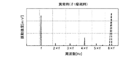
図5は、実施の形態1に係る圧縮機システムの分析部における正常時の周波数分析結果の一例を示す図である。図6は、実施の形態1に係る圧縮機システムの分析部における異常時の周波数分析結果の一例を示す図である。図5および図6において、横軸は周波数[Hz]、縦軸は振動強度[m/s]である。fはモータ4の回転周波数である。振動強度は加速度である。図5および図6は、振動値を周波数分析した結果を示しているが、電流値を周波数分析した結果も同様の結果となる。図6は、空隙の個数が3個の場合の異常時の周波数分析結果を示している。FIG. 5 is a diagram showing an example of a normal frequency analysis result in the analysis unit of the compressor system according to Embodiment 1. FIG. FIG. 6 is a diagram showing an example of a frequency analysis result at the time of abnormality in the analysis unit of the compressor system according to Embodiment 1. FIG. 5 and 6, the horizontal axis is frequency [Hz] and the vertical axis is vibration intensity [m/s 2 ]. f is the rotation frequency of the motor 4; Vibration intensity is acceleration. 5 and 6 show the results of frequency analysis of vibration values, and the results of frequency analysis of current values are similar. FIG. 6 shows the frequency analysis results at the time of abnormality when the number of air gaps is three.

正常時は、図5に示すようにモータ4の回転周波数fの1次成分が主にピークとして検知される。異常時は、つまり許容摩耗量の摩擦が発生した時は、図6に示すように、空隙83の個数である「3」と回転周波数「f」との積によって算出される3×fの周波数において、ピーク値が設定値を超える異常ピークが発生する。 In normal operation, as shown in FIG. 5, the primary component of the rotation frequency f of the motor 4 is mainly detected as a peak. In the abnormal state, that is, when friction of the allowable amount of wear occurs, as shown in FIG. , an abnormal peak occurs in which the peak value exceeds the set value.

したがって、摩耗検知部202は、分析部201で得られた周波数分析結果において、3×fの周波数におけるピーク値が、予め設定した設定値を超えている場合、異常が発生したと検知する。 Therefore, the wear detection unit 202 detects that an abnormality has occurred when the peak value at the frequency of 3×f exceeds a preset value in the frequency analysis result obtained by the analysis unit 201 .

摩耗検知部202が異常を検知した場合は、圧縮機100の寿命が近いことを意味する。このため、制御装置200は、運転中の最高回転周波数を下げるように圧縮機100を制御する。例えば、運転中の最高回転周波数を、正常時の最高回転周波数の80%等にする。また、制御装置200は、摩耗検知部202が異常を検知した場合、異常が発生した旨をメンテナンス会社に通知する。メンテナンス会社の作業員は、通知により圧縮機100の寿命が近くなっていることが分かるため、交換用圧縮機の準備を実施する。 When the wear detection unit 202 detects an abnormality, it means that the life of the compressor 100 is nearing the end of its life. Therefore, the controller 200 controls the compressor 100 so as to lower the maximum rotational frequency during operation. For example, the maximum rotation frequency during operation is set to 80% of the maximum rotation frequency during normal operation. Further, when the wear detection unit 202 detects an abnormality, the control device 200 notifies the maintenance company of the occurrence of the abnormality. A worker at the maintenance company is informed that the life of the compressor 100 is nearing the end of its life, and prepares a replacement compressor.

ここで、空隙83の個数は、複数個であればよいが、3個以上が望ましい。これは、以下の理由による。振動値または電流値の周波数分析結果においては、上述したようにモータ4の回転周波数fの1次成分が大きく検知される。このため、空隙83が1つであると、空隙83の有無による振動値または電流値の変化を検知できない可能性がある。したがって、空隙83は3個以上が望ましい。また、軸受80の信頼性の観点から空隙83は6個以下が望ましい。 Here, the number of air gaps 83 may be plural, but preferably three or more. This is for the following reasons. In the result of frequency analysis of the vibration value or current value, the first-order component of the rotation frequency f of the motor 4 is largely detected as described above. Therefore, if there is only one air gap 83, there is a possibility that changes in the vibration value or current value due to the presence or absence of the air gap 83 cannot be detected. Therefore, it is desirable that the number of gaps 83 is three or more. Also, from the viewpoint of reliability of the bearing 80, the number of the gaps 83 is desirably six or less.

なお、周波数分析を実施するのは振動値および電流値のどちらでもよいが、両方実施することで、故障検知への精度がより向上する。つまり、振動値および電流値の両方の周波数分析結果において、空隙83の個数N×回転周波数fの周波数にて異常ピークが発生している場合に異常と判定する。これにより、より精度の高い検知結果を得ることができ、故障検知精度が高まる。 Note that frequency analysis may be performed on either the vibration value or the current value, but by performing both, the accuracy of failure detection is further improved. In other words, in the frequency analysis results of both the vibration value and the current value, if an abnormal peak occurs at a frequency of the number of gaps 83 N×rotational frequency f, it is determined to be abnormal. As a result, more accurate detection results can be obtained, and failure detection accuracy increases.

以上、摩擦異常の検知対象を、主軸受8aおよび揺動軸受8cの一方とする場合について説明した。主軸受8aおよび揺動軸受8cのうち、どちらが摩耗しやすいか、圧縮機100の仕様および使用方法によって予め判明している場合は、摩耗しやすい方の軸受のみに複数の空隙83を設けた構造とすればよい。 In the above, the case where one of the main bearing 8a and the oscillating bearing 8c is to be detected for friction abnormality has been described. If it is known in advance which of the main bearing 8a and the rocking bearing 8c is more likely to wear depending on the specifications and usage of the compressor 100, a structure in which a plurality of gaps 83 are provided only in the bearing that is more likely to wear. And it is sufficient.

[実施の形態1の効果]
本実施の形態1の圧縮機システムは、回転軸7を支持する軸受80を有する圧縮機100と、圧縮機100の運転中の回転軸7の動きと相関がある指標値を測定するセンサーと、センサーの測定値に基づいて軸受の摩耗具合を検知する摩耗検知部202とを備える。軸受80はすべり軸受で構成されており、軸受80において周方向に間隔を空けて複数の空隙83が形成され、軸受80の摩耗により、軸受80の内周面82aと複数の空隙83との位置関係が変化して軸受80の内周面形状が変化するように構成されている。摩耗検知部202は、軸受80の内周面形状の変化に起因する測定値の変化に基づいて軸受80の摩耗具合を検知する。
[Effect of Embodiment 1]
The compressor system of the first embodiment includes a compressor 100 having a bearing 80 that supports the rotating shaft 7, a sensor that measures an index value correlated with the movement of the rotating shaft 7 during operation of the compressor 100, and a wear detection unit 202 for detecting the degree of wear of the bearing based on the measured value of the sensor. The bearing 80 is composed of a slide bearing, and a plurality of gaps 83 are formed in the bearing 80 at intervals in the circumferential direction. It is configured such that the inner peripheral surface shape of the bearing 80 changes as the relationship changes. The wear detector 202 detects the degree of wear of the bearing 80 based on changes in the measured values caused by changes in the shape of the inner peripheral surface of the bearing 80 .

これにより、軸受80に複数の空隙83を設けただけの簡易な構造で軸受80の摩耗具合の検知が可能となる。そして、軸受80の摩耗具合を検知できることで、異常状態の早期検知が可能となり、圧縮機100が完全に停止する前に、新しい圧縮機に交換することが可能となる。 As a result, it is possible to detect the degree of wear of the bearing 80 with a simple structure in which a plurality of gaps 83 are provided in the bearing 80 . Further, by being able to detect the degree of wear of the bearing 80, an abnormal state can be detected early, and it becomes possible to replace the compressor 100 with a new one before the compressor 100 completely stops.

軸受80の内周面から複数の空隙83の少なくとも一部の空隙までの径方向の距離が、摩耗量の許容限度を示す許容摩耗量に設定されている。 A radial distance from the inner peripheral surface of the bearing 80 to at least some of the plurality of gaps 83 is set to an allowable wear amount indicating an allowable limit of the wear amount.

これにより、摩耗量が許容摩耗量を超えた摩耗異常を検知できる。 As a result, it is possible to detect wear abnormality in which the amount of wear exceeds the allowable amount of wear.

本実施の形態1は、軸受80は、円筒状の裏金81と、裏金81の内側に設けられた円筒状の合金82とを備えており、複数の空隙83は合金82の外周面に形成されている。 In the first embodiment, the bearing 80 includes a cylindrical back metal 81 and a cylindrical alloy 82 provided inside the back metal 81, and a plurality of gaps 83 are formed on the outer peripheral surface of the alloy 82. ing.

このような構成によって、軸受80に複数の空隙83を設けた構成を得ることができる。 With such a configuration, a configuration in which a plurality of gaps 83 are provided in the bearing 80 can be obtained.

指標値は、圧縮機の振動を示す振動値または圧縮機を流れる電流値である。 The index value is a vibration value indicating vibration of the compressor or a current value flowing through the compressor.

このように、圧縮機100の運転中の回転軸7の動きと相関がある指標値として振動値または電流値を用いることができる。 Thus, the vibration value or the current value can be used as an index value that correlates with the movement of the rotating shaft 7 during operation of the compressor 100 .

[実施の形態2]
実施の形態2は、軸受80の内周面82aからの径方向の距離が異なる複数種類の空隙を軸受80に設けた構成を有する。以下、実施の形態2が実施の形態1と異なる構成を中心に説明する。
[Embodiment 2]
Embodiment 2 has a configuration in which a plurality of types of gaps having different radial distances from the inner peripheral surface 82a of the bearing 80 are provided in the bearing 80 . The following description focuses on the configuration of the second embodiment that differs from that of the first embodiment.

図7は、実施の形態2に係る圧縮機の軸受の概略断面図である。図8は、図7の第2空隙を含む周辺部分の拡大断面図である。
実施の形態2の軸受80Aは、軸受80Aの内周面からの距離が異なる2種類の第1空隙84aと第2空隙84bとを有する。第1空隙84aおよび第2空隙84bは、合金82の外周面に形成された凹部で構成されており、凹部の深さが異なることで、軸受80Aの内周面からの距離が異なる構成となっている。第1空隙84aを形成する凹部の底面84a1と内周面82aとの距離は図3と同様にδ1である。第2空隙84bを形成する凹部の底面84b1と内周面82aとの距離は、図8に示すようにδ2である。δ1とδ2とは、δ1>δ2の関係を有する。
7 is a schematic cross-sectional view of a bearing of a compressor according to Embodiment 2. FIG. 8 is an enlarged cross-sectional view of the peripheral portion including the second gap in FIG. 7. FIG.
A bearing 80A of the second embodiment has two types of first gaps 84a and second gaps 84b with different distances from the inner peripheral surface of the bearing 80A. The first gap 84a and the second gap 84b are configured by recesses formed in the outer peripheral surface of the alloy 82, and the depths of the recesses are different, so that the distances from the inner peripheral surface of the bearing 80A are different. ing. The distance between the bottom surface 84a1 of the recess forming the first gap 84a and the inner peripheral surface 82a is .delta.1 as in FIG. The distance between the bottom surface 84b1 of the recess forming the second gap 84b and the inner peripheral surface 82a is δ2 as shown in FIG. δ1 and δ2 have a relationship of δ1>δ2.

第1空隙84aの数と第2空隙84bの数とは同一であり、ここでは3つである。第1空隙84aと第2空隙84bの配置は交互となっており、等間隔の配置となっている。すなわち、各種類の空隙は、種類毎に交互であって、各空隙同士の間隔が周方向において等間隔の配置となっている。このような配置とすることで、周波数分析結果において、空隙の個数×fの周波数において異常ピークを検出することができる。 The number of the first gaps 84a and the number of the second gaps 84b are the same, which is three here. The first gaps 84a and the second gaps 84b are arranged alternately and are arranged at regular intervals. In other words, the gaps of each type are arranged alternately for each type, and the gaps between the gaps are arranged at equal intervals in the circumferential direction. With such an arrangement, an abnormal peak can be detected at a frequency of the number of voids×f in the frequency analysis result.

図9は、実施の形態2に係る圧縮機システムの分析部におけるδ1摩耗時の周波数分析結果の一例を示す図である。
軸受80Aにおいて、δ2の摩耗が生じた場合、実施の形態1と同様に、図6に示したように、3×fの周波数において、異常ピークが発生する。そして、軸受80Aの摩擦がさらに進んでδ1の摩擦が生じた場合、軸受80Aでは計6個の空隙が軸受80Aの内側空間に連通した状態となり、図9に示すように6×fの周波数において異常ピークが発生する。
FIG. 9 is a diagram showing an example of frequency analysis results at the time of δ1 wear in the analysis unit of the compressor system according to Embodiment 2. FIG.
When wear of δ2 occurs in the bearing 80A, as in the first embodiment, an abnormal peak occurs at a frequency of 3×f, as shown in FIG. Then, when the friction of the bearing 80A further progresses and the friction of δ1 occurs, a total of six air gaps in the bearing 80A communicate with the inner space of the bearing 80A, and as shown in FIG. Abnormal peaks occur.

したがって、軸受80の内周面82aからの距離が異なる2種類の空隙が軸受80Aに3個ずつ設けられていることが予め分かっていれば、周波数分析結果において、3×fの周波数において異常ピークが発生していれば、δ2の摩耗が発生したことを検知できる。また、6×fの周波数において異常ピークが発生した場合、δ1の摩耗が発生したことを検知できる。 Therefore, if it is known in advance that each of the two types of air gaps having different distances from the inner peripheral surface 82a of the bearing 80 is provided in the bearing 80A, the frequency analysis results show an abnormal peak at the frequency of 3×f. is generated, it can be detected that the wear of .delta.2 is generated. Also, when an abnormal peak occurs at a frequency of 6×f, it can be detected that wear of δ1 has occurred.

なお、ここでは、空隙の種類を2種類としたが、3種類以上としてもよい。この場合も、各種類の空隙の数を同数とし、各種類毎に交互であって、各空隙同士の間隔が周方向において等間隔の配置とすることで、上記と同様にして摩耗を検知できる。 Although two kinds of voids are used here, three or more kinds of voids may be used. Also in this case, the number of each type of gap is the same, and each type is alternately arranged, and the intervals between the gaps are arranged at equal intervals in the circumferential direction, so that wear can be detected in the same manner as described above. .

[実施の形態2の効果]
実施の形態2によれば、実施の形態1と同様の効果が得られるとともに、以下の効果が得られる。実施の形態2では、深さの異なる2種類の空隙を軸受80Aに設けたことで、摩耗量の進行度合いを検知できる。このため、圧縮機交換の緊急度を確認することが可能となる。上記実施の形態1では、許容摩擦量δ1の摩耗が生じた摩耗異常を検知しており、圧縮機100が完全に停止する状況に近い状況にあり、早急の圧縮機交換が必要である。これに対し、実施の形態2では、許容摩擦量δ1の摩耗に達する前のδ2の摩耗が生じたことについても検知できるため、交換までに猶予があることを知ることができる。したがって、例えば複数の圧縮機100を管理している場合において、交換用の圧縮機の数量が潤沢にない場合は、優先順位をつけて交換することが可能となる。
[Effect of Embodiment 2]
According to the second embodiment, the same effects as those of the first embodiment can be obtained, and the following effects can be obtained. In the second embodiment, two types of gaps with different depths are provided in the bearing 80A, so that the progress of the amount of wear can be detected. Therefore, it is possible to confirm the degree of urgency of compressor replacement. In Embodiment 1 above, wear abnormality in which wear of the allowable friction amount δ1 has occurred is detected, and the situation is close to a situation in which the compressor 100 completely stops, and urgent replacement of the compressor is required. On the other hand, in Embodiment 2, it is possible to detect that the wear of δ2 has occurred before the wear of the allowable friction amount δ1 has occurred, so that it is possible to know that there is time before replacement. Therefore, for example, when a plurality of compressors 100 are managed, if the number of compressors for replacement is not sufficient, it is possible to prioritize the replacement.

[実施の形態3]
実施の形態3では、主軸受8aおよび揺動軸受8cの両方を、摩擦異常の検知対象とする場合について説明する。以下、実施の形態3が実施の形態1と異なる構成を中心に説明する。
[Embodiment 3]
In the third embodiment, a case will be described in which both the main bearing 8a and the rocking bearing 8c are subject to friction abnormality detection. The following description focuses on the configuration of the third embodiment that differs from the first embodiment.

主軸受8aおよび揺動軸受8cの両方を、摩擦異常の検知対象とする場合は、主軸受8aおよび揺動軸受8cのそれぞれに空隙を設ける。空隙の配置位置は、主軸受8a側に設ける空隙と揺動軸受8c側に設ける空隙とで同一位相にないことが好ましい。同一位相にあると、振動が増幅されて圧縮機100の信頼性が低くなるためである。 When both the main bearing 8a and the oscillating bearing 8c are to be subjected to friction abnormality detection, a gap is provided in each of the main bearing 8a and the oscillating bearing 8c. It is preferable that the arrangement positions of the gaps are not in the same phase between the gap provided on the main bearing 8a side and the gap provided on the swing bearing 8c side. This is because if they are in the same phase, the vibration is amplified and the reliability of the compressor 100 is lowered.

主軸受8aおよび揺動軸受8cの両方に空隙を設ける場合として、以下の3パターンについて説明する。
パターン1:主軸受8aおよび揺動軸受8cのそれぞれの空隙の個数が同じ場合。
パターン2:主軸受8aおよび揺動軸受8cのそれぞれの空隙の個数が異なる場合。
パターン3:実施の形態2を適用し、主軸受8aおよび揺動軸受8cのそれぞれに、深さの異なる2種類の空隙を設けた場合。
The following three patterns will be described as cases where gaps are provided in both the main bearing 8a and the rocking bearing 8c.
Pattern 1: When the number of gaps in the main bearing 8a and the oscillating bearing 8c are the same.
Pattern 2: When the numbers of gaps are different between the main bearing 8a and the oscillating bearing 8c.
Pattern 3: When Embodiment 2 is applied and two types of gaps with different depths are provided in each of the main bearing 8a and the rocking bearing 8c.

(パターン1)
図10は、実施の形態3に係る圧縮機システムにおけるパターン1の場合の異常発生の軸受と、周波数分析に基づく異常ピークの発生周波数との関係を示す図である。
図10は、主軸受8aおよび揺動軸受8cのそれぞれに、N個ずつ、同一位相にならないように空隙を設けた場合の異常発生の軸受と、異常ピークの発生周波数との関係を示している。
(Pattern 1)
FIG. 10 is a diagram showing a relationship between a bearing in which an abnormality occurs and an occurrence frequency of an abnormal peak based on frequency analysis in the case of pattern 1 in the compressor system according to the third embodiment.
FIG. 10 shows the relationship between the occurrence frequency of abnormal peaks and the occurrence of abnormal peaks when N gaps are provided in each of the main bearing 8a and the oscillating bearing 8c so as not to have the same phase. .

図10より、例えばN=3個ずつ、同一位相にならないように空隙を設けた場合、主軸受8aのみに摩擦異常が発生した場合、3×fの周波数において異常ピークが発生する。また、揺動軸受8cのみに摩擦異常が発生した場合も、3×fの周波数において異常ピークが発生する。そして主軸受8aおよび揺動軸受8cの両方に摩擦異常が発生した場合、2×3×fの周波数において異常ピークが発生する。 From FIG. 10, for example, when N=3 air gaps are provided so as not to have the same phase, when friction abnormality occurs only in the main bearing 8a, an abnormal peak occurs at a frequency of 3×f. Also, when frictional abnormality occurs only in the rocking bearing 8c, an abnormal peak occurs at the frequency of 3×f. When frictional abnormality occurs in both the main bearing 8a and the rocking bearing 8c, an abnormal peak occurs at a frequency of 2.times.3.times.f.

したがって、周波数分析結果において、3×fの周波数において異常ピークが発生している場合、主軸受8aおよび揺動軸受8cのどちらかに異常が発生していることを検知できる。そして、周波数6fにおいて異常ピークが発生している場合、主軸受8aおよび揺動軸受8cの両方に異常が発生していることを検知できる。 Therefore, when an abnormal peak occurs at the frequency of 3×f in the frequency analysis result, it can be detected that either the main bearing 8a or the rocking bearing 8c has an abnormality. Then, when an abnormal peak occurs at the frequency 6f, it can be detected that both the main bearing 8a and the rocking bearing 8c are abnormal.

(パターン2)
図11は、実施の形態3に係る圧縮機システムにおけるパターン2の場合の異常発生の軸受と、周波数分析に基づく異常ピークの発生周波数との関係を示す図である。図11は、主軸受8aの空隙がN個、揺動軸受8cの空隙がM個であり、同一位相にならないように空隙を設けた場合の異常発生の軸受と、異常ピークの発生周波数との関係を示している。
(Pattern 2)
FIG. 11 is a diagram showing the relationship between the abnormal peak occurrence frequency based on the frequency analysis and the abnormal bearing in pattern 2 in the compressor system according to the third embodiment. FIG. 11 shows the relationship between the abnormal peak occurrence frequency and the bearing in which the main bearing 8a has N air gaps and the oscillating bearing 8c has M air gaps, and the air gaps are provided so as not to have the same phase. showing relationships.

異常発生の軸受と、異常ピークの発生周波数と間には図11に示す関係があるため、N×fの周波数に異常ピークが発生していれば、主軸受8aに異常が発生したことを検知できる。また、M×fの周波数に異常ピークが発生していれば、揺動軸受8cに異常が発生したことを検知できる。また、N×fの周波数とM×fの周波数との両方に異常ピークが発生していれば、主軸受8aと揺動軸受8cとの両方に異常が発生したことを検知できる。 Since there is a relationship shown in FIG. 11 between the abnormal bearing and the occurrence frequency of the abnormal peak, if the abnormal peak occurs at the frequency of N×f, it is detected that the main bearing 8a is abnormal. can. Further, if an abnormal peak occurs at the frequency of M×f, it can be detected that an abnormality has occurred in the rocking bearing 8c. Further, if abnormal peaks occur in both the N×f frequency and the M×f frequency, it can be detected that both the main bearing 8a and the rocking bearing 8c have an abnormality.

このパターン3のように、主軸受8aおよび揺動軸受8cのそれぞれの空隙の個数を異ならせた場合、主軸受8aおよび揺動軸受8cのどちらで摩耗異常が発生したのか、つまり摩耗箇所を検知することができる。 When the number of gaps is different between the main bearing 8a and the rocking bearing 8c as in pattern 3, it is possible to detect which of the main bearing 8a and rocking bearing 8c has abnormal wear, that is, the location of wear. can do.

(パターン3)
図12は、実施の形態3に係る圧縮機システムにおけるパターン3の場合の異常発生の軸受と、周波数分析に基づく異常ピークの発生周波数との関係を示す図である。図12は以下の配置の場合における、異常発生の軸受と異常ピークの発生周波数との関係を示している。すなわち、主軸受8aに、深さの異なる2種類の第1空隙84aおよび第2空隙84bがそれぞれN個ずつ設けられている。また、揺動軸受8cに、深さの異なる第1空隙84aおよび第2空隙84bがそれぞれM個ずつ設けられている。主軸受8aおよび揺動軸受8cのそれぞれにおいて、各種類の空隙は、種類毎に交互であって、各空隙同士の間隔が周方向において等間隔の配置となっている。また、主軸受8aと揺動軸受8cとにおいて同一位相にならないように各空隙が配置されている。
(Pattern 3)
FIG. 12 is a diagram showing the relationship between a bearing in which an abnormality occurs in pattern 3 in the compressor system according to Embodiment 3 and the frequency of occurrence of an abnormal peak based on frequency analysis. FIG. 12 shows the relationship between the occurrence frequency of abnormal peaks and abnormal bearings in the following arrangement. That is, the main bearing 8a is provided with N first gaps 84a and N second gaps 84b of two different depths. Further, M first gaps 84a and M second gaps 84b having different depths are provided in the rocking bearing 8c. In each of the main bearing 8a and the oscillating bearing 8c, the types of gaps are alternated for each type, and the intervals between the gaps are arranged at equal intervals in the circumferential direction. Further, the gaps are arranged so that the main bearing 8a and the rocking bearing 8c are not in the same phase.

このパターン3の場合も、パターン1およびパターン2と考え方は同じであり、図12に示した関係があるため、この関係を予め知っていることで、摩耗箇所と摩耗量の進行度合いとを検知できる。例えば、N×fの周波数のみに異常ピークが発生していれば、主軸受8aのみにδ2の摩耗が発生していることを検知できる。また、N×fとM×fの2つの周波数において異常ピークが発生していれば、主軸受8aおよび揺動軸受8cの両方に、δ2の摩耗が発生していることを検知できる。また、(2×N)×fと(2×M)×fの両方の周波数に異常ピークが発生していれば、主軸受8aおよび揺動軸受8cの両方にδ1の摩擦が生じ、異常が発生していることを検知できる。 In the case of this pattern 3 as well, the idea is the same as that of patterns 1 and 2, and since there is a relationship shown in FIG. can. For example, if an abnormal peak occurs only at the frequency of N×f, it can be detected that wear of δ2 has occurred only in the main bearing 8a. Also, if abnormal peaks occur at two frequencies of N×f and M×f, it can be detected that wear of δ2 has occurred in both the main bearing 8a and the rocking bearing 8c. Also, if abnormal peaks occur at both frequencies of (2×N)×f and (2×M)×f, friction of δ1 occurs in both the main bearing 8a and the rocking bearing 8c, causing an abnormality. You can detect what is happening.

なお、ここでは、空隙の種類を2種類としたが、3種類以上としてもよい。この場合も、主軸受8aおよび揺動軸受8cのそれぞれにおいて、各種類の空隙の数を同数とし、各種類毎に交互であって、各空隙同士の間隔が周方向において等間隔の配置とすることで、上記と同様にして摩耗を検知できる。 Although two kinds of voids are used here, three or more kinds of voids may be used. In this case also, the main bearing 8a and the oscillating bearing 8c each have the same number of gaps of each type, alternately for each type, and arranged at equal intervals in the circumferential direction. Therefore, wear can be detected in the same manner as described above.

[実施の形態3の効果]
実施の形態3によれば、主軸受8aおよび揺動軸受8cの両方に空隙を設けておくことで、両方の軸受異常を検知できる。
[Effect of Embodiment 3]
According to Embodiment 3, by providing gaps in both the main bearing 8a and the rocking bearing 8c, it is possible to detect both bearing abnormalities.

また、主軸受8aおよび揺動軸受8cのそれぞれの空隙の個数を異ならせておくことで、主軸受8aおよび揺動軸受8cのどちらで摩耗異常が発生したのか、つまり摩耗箇所を検知することができる。したがって、冷凍サイクル装置の運転方法と摩耗箇所とを関連付けることにより、摩耗量が小さくなるように冷凍サイクル装置の運転方法の是正をすることができ、圧縮機100の信頼性向上に寄与できる。例えば、液バックが生じた場合には揺動軸受8cの摩耗が進みやすいため、揺動軸受8cの摩耗異常を検知した場合、液バックが生じない運転に変更するといった対応が可能である。 Also, by varying the number of gaps between the main bearing 8a and the oscillating bearing 8c, it is possible to detect in which of the main bearing 8a and the oscillating bearing 8c abnormal wear has occurred, that is, the location of wear. can. Therefore, by associating the operating method of the refrigerating cycle device with the worn portion, the operating method of the refrigerating cycle device can be corrected so as to reduce the amount of wear, which contributes to improving the reliability of the compressor 100 . For example, when liquid backflow occurs, wear of the rocking bearing 8c is likely to progress. Therefore, when abnormal wear of the rocking bearing 8c is detected, it is possible to change the operation to one in which liquid backflow does not occur.

また、実施の形態3では、主軸受8aおよび揺動軸受8cのそれぞれの空隙の個数を異ならせ、さらに、各軸受の空隙を深さの異なる複数種の同数の空隙で構成し、主軸受8aおよび揺動軸受8cのそれぞれにおいて、各種類の空隙を、種類毎に交互であって、各空隙同士の間隔が周方向において等間隔に配置した構成とした。これにより、摩擦箇所と摩擦量の進行度合いとの両方を検知できる。 Further, in Embodiment 3, the number of gaps in the main bearing 8a and the oscillating bearing 8c is made different, and furthermore, the gaps in each bearing are composed of the same number of gaps of a plurality of types with different depths, and the main bearing 8a and oscillating bearing 8c, each kind of gap is arranged alternately for each kind, and the gaps between the gaps are arranged at regular intervals in the circumferential direction. This makes it possible to detect both the location of friction and the progress of the amount of friction.

[実施の形態4]
実施の形態4は、軸受の内周面に空隙を設けたものである。以下、実施の形態4が実施の形態1と異なる構成を中心に説明する。また、実施の形態4では、摩擦異常の検知対象を、主軸受8aおよび揺動軸受8cの一方とする場合について説明する。
[Embodiment 4]
In the fourth embodiment, a gap is provided on the inner peripheral surface of the bearing. The following description focuses on the configuration of the fourth embodiment that differs from that of the first embodiment. Further, in the fourth embodiment, a case where one of the main bearing 8a and the rocking bearing 8c is to be detected for friction abnormality will be described.

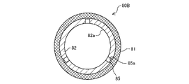
図13は、実施の形態4に係る圧縮機システムにおける軸受の概略断面図である。図14は、図13の空隙を含む周辺部分の拡大概略断面図である。
実施の形態4の軸受80Bは、軸受80Bの内周面82aに複数の空隙85を設けた構成を有する。空隙85は内周面82aに形成された凹部によって構成されている。空隙85を構成する凹部の底面85aと軸受80Bの内周面82aとの間の第一距離δ1(図14参照)は、ここでは許容摩耗量に設定した例を示しているが、δ1よりも短いδ2に設定してもよい。空隙85を構成する凹部の底面85aと軸受80Bの内周面82aとの間の第一距離は、どの程度の摩耗を検知したいかに応じて適宜設定すればよい。
13 is a schematic cross-sectional view of a bearing in a compressor system according to Embodiment 4. FIG. 14 is an enlarged schematic cross-sectional view of the peripheral portion including the gap in FIG. 13. FIG.
A bearing 80B of Embodiment 4 has a configuration in which a plurality of gaps 85 are provided in an inner peripheral surface 82a of the bearing 80B. The gap 85 is formed by a recess formed in the inner peripheral surface 82a. The first distance δ1 (see FIG. 14) between the bottom surface 85a of the recess forming the air gap 85 and the inner peripheral surface 82a of the bearing 80B is set to the allowable wear amount here. It may be set to a short δ2. The first distance between the bottom surface 85a of the recess forming the air gap 85 and the inner peripheral surface 82a of the bearing 80B may be appropriately set according to the degree of wear to be detected.

[摩擦異常検知原理]
図15は、実施の形態4に係る圧縮機システムにおける正常時の周波数分析結果の一例を示す図である。図16は、実施の形態4に係る圧縮機システムにおける異常時の周波数分析結果の一例を示す図である。ここでは、軸受80Bの空隙85の個数が3個の例を示している。
[Friction anomaly detection principle]
FIG. 15 is a diagram showing an example of frequency analysis results during normal operation in the compressor system according to the fourth embodiment. FIG. 16 is a diagram showing an example of a frequency analysis result when there is an abnormality in the compressor system according to Embodiment 4. FIG. Here, an example is shown in which the number of air gaps 85 in the bearing 80B is three.

実施の形態4においては、正常時において3個の空隙85が軸受80Bの内側空間に連通した状態となっているため、図15に示すように、3×fの周波数に、設定値を超えるピーク値を有する正常ピークが発生している。そして、軸受80Bの摩耗が進行し、軸受80Bに設けた空隙が無くなって軸受80Bの内周面82aが、全周において面一の状態に面形状が変化すると、図16に示すように3×fの周波数における正常ピークが無くなる。したがって、軸受80Bに空隙85が3個設けられていることが分かっていれば、周波数分析結果において3×fの周波数において設定値を超えるピークが発生していなければ、摩耗異常が発生したことを検知できる。 In the fourth embodiment, since the three air gaps 85 communicate with the inner space of the bearing 80B in the normal state, as shown in FIG. A normal peak with values occurs. Then, when the wear of the bearing 80B progresses and the air gap provided in the bearing 80B disappears and the inner peripheral surface 82a of the bearing 80B changes its surface shape to be flush with the entire circumference, the surface shape changes to 3× as shown in FIG. Normal peaks at frequencies of f disappear. Therefore, if it is known that three air gaps 85 are provided in the bearing 80B, and if no peak exceeding the set value occurs at the frequency of 3×f in the frequency analysis result, it means that the wear abnormality has occurred. detectable.

ここでは、摩擦異常の検知対象を、主軸受8aおよび揺動軸受8cの一方とする場合について説明したが、主軸受8aおよび揺動軸受8cの両方を摩擦異常の検知対象とした場合も同様にして異常検知を行える。この場合、主軸受8aおよび揺動軸受8cのそれぞれの内周面に空隙を設ける。主軸受8aに例えば空隙を3つ、揺動軸受8cに例えば空隙を4つ設けた場合、正常時の周波数分析結果および異常時の周波数結果は、次の図17~図19に示すようになる。 Here, the case where one of the main bearing 8a and the oscillating bearing 8c is targeted for detection of frictional abnormality has been described, but the same applies to the case where both the main bearing 8a and the oscillating bearing 8c are targeted for detection of frictional abnormality. anomaly detection. In this case, a gap is provided in each inner peripheral surface of the main bearing 8a and the rocking bearing 8c. When the main bearing 8a is provided with, for example, three air gaps, and the oscillating bearing 8c is provided with, for example, four air gaps, the results of frequency analysis in the normal state and in the abnormal state are shown in FIGS. 17 to 19 below. .

図17は、実施の形態4に係る圧縮機システムにおける主軸受および揺動軸受の両方に空隙を設けた場合の正常時の周波数分析結果の一例を示す図である。図18は、実施の形態4に係る圧縮機システムにおいて主軸受のみに摩耗異常が発生した場合の周波数分析結果を示す図である。図19は、実施の形態4に係る圧縮機システムにおいて揺動軸受のみに摩耗異常が発生した場合の周波数分析結果を示す図である。 FIG. 17 is a diagram showing an example of a frequency analysis result during normal operation when gaps are provided in both the main bearing and the oscillating bearing in the compressor system according to the fourth embodiment. FIG. 18 is a diagram showing frequency analysis results when wear abnormality occurs only in the main bearing in the compressor system according to the fourth embodiment. FIG. 19 is a diagram showing frequency analysis results when wear abnormality occurs only in the rocking bearing in the compressor system according to the fourth embodiment.

図17に示すように、正常時には、3×fの周波数と4×fの周波数に正常ピークが発生している。そして、主軸受8aのみに摩耗異常が発生した場合、図18に示す周波数結果となる。揺動軸受8cのみに摩耗異常が発生した場合、図19に示す周波数結果となる。したがって、主軸受8aの内周面に空隙が3個、揺動軸受8cの内周面に空隙が4個設けられていることが分かっていれば、図18に示すように周波数分析結果において3×fの周波数において設定値を超える正常ピークが発生していなければ、主軸受8aに摩耗異常が発生したことを検知できる。また、周波数分析結果において4×fの周波数において設定値を超える正常ピークが発生していなければ、揺動軸受8cに摩耗異常が発生したことを検知できる。 As shown in FIG. 17, normal peaks occur at frequencies of 3×f and 4×f in normal operation. When wear abnormality occurs only in the main bearing 8a, the frequency results shown in FIG. 18 are obtained. When wear abnormality occurs only in the rocking bearing 8c, the frequency results shown in FIG. 19 are obtained. Therefore, if it is known that there are three air gaps on the inner peripheral surface of the main bearing 8a and four air gaps on the inner peripheral surface of the rocking bearing 8c, the frequency analysis result will show three gaps as shown in FIG. If a normal peak exceeding the set value does not occur at the frequency of xf, it can be detected that the main bearing 8a has abnormal wear. Further, if a normal peak exceeding the set value does not occur at the frequency of 4×f in the frequency analysis result, it can be detected that the rocking bearing 8c has abnormal wear.

[実施の形態4の効果]
実施の形態4によれば、実施の形態1と同様の効果を得ることができる。また、上記実施の形態1から実施の形態3では、摩耗が進むと許容摩耗肉厚部82bが薄くなるため、許容摩耗肉厚部82bを適切に設定していないと、軸受荷重が付加された場合に、許容摩耗量の摩耗に達する前に許容摩耗肉厚部82bが空隙内に陥没する可能性がある。そのため、摩耗量が許容摩耗量に達する前に異常ピークが発生する可能性があり、摩擦異常を正確に検知することができない。これに対し、実施の形態4では、そもそも許容摩耗肉厚部82bが設けられていないので、このような陥没を回避でき、摩擦異常を正確に検知できる。
[Effect of Embodiment 4]
According to the fourth embodiment, effects similar to those of the first embodiment can be obtained. Further, in Embodiments 1 to 3, as the wear progresses, the allowable wear thick portion 82b becomes thinner. In this case, there is a possibility that the allowable wear thick portion 82b will collapse into the gap before reaching the allowable wear amount. Therefore, there is a possibility that an abnormal peak will occur before the amount of wear reaches the allowable amount of wear, and frictional abnormality cannot be detected accurately. On the other hand, in Embodiment 4, since the allowable wear thick portion 82b is not provided in the first place, such depression can be avoided and the frictional abnormality can be accurately detected.

[実施の形態5]
実施の形態5は、実施の形態1~実施の形態4のいずれかの圧縮機システムを備えた冷凍サイクル装置に関するものである。
[Embodiment 5]
Embodiment 5 relates to a refrigeration cycle apparatus including the compressor system according to any one of Embodiments 1 to 4.

図20は、実施の形態5に係る冷凍サイクル装置の冷媒回路を示す図である。
冷凍サイクル装置300は、実施の形態1~実施の形態4のいずれかの圧縮機システムを備えている。そして、冷凍サイクル装置300は、圧縮機100と、凝縮器301と、減圧装置としての膨張弁302と、蒸発器303とを備えている。圧縮機システムの圧縮機100から吐出されたガス冷媒は凝縮器301に流入し、凝縮器301を通過する空気と熱交換して高圧液冷媒となって流出する。凝縮器301を流出した高圧液冷媒は膨張弁302で減圧されて低圧の気液二相冷媒となり、蒸発器303に流入する。蒸発器303に流入した低圧の気液二相冷媒は、蒸発器303を通過する空気と熱交換して低圧ガス冷媒となり、再び圧縮機100に吸入される。
20 is a diagram showing a refrigerant circuit of a refrigeration cycle apparatus according to Embodiment 5. FIG.
A refrigeration cycle apparatus 300 includes the compressor system according to any one of the first to fourth embodiments. The refrigeration cycle device 300 includes a compressor 100 , a condenser 301 , an expansion valve 302 as a decompression device, and an evaporator 303 . Gas refrigerant discharged from the compressor 100 of the compressor system flows into the condenser 301, exchanges heat with the air passing through the condenser 301, and flows out as a high-pressure liquid refrigerant. The high-pressure liquid refrigerant that has flowed out of the condenser 301 is decompressed by the expansion valve 302 to become a low-pressure gas-liquid two-phase refrigerant and flows into the evaporator 303 . The low-pressure gas-liquid two-phase refrigerant that has flowed into the evaporator 303 exchanges heat with the air passing through the evaporator 303 to become low-pressure gas refrigerant, which is sucked into the compressor 100 again.

このように構成された冷凍サイクル装置300は、実施の形態1~実施の形態4のいずれかの圧縮機システムを備えることで、圧縮機100の異常状態の早期検知が可能となり、圧縮機が完全に停止する前に、新しい圧縮機に交換することが可能となる。これにより、冷凍サイクルが停止して、顧客が不利益をこうむることがなくなる。 The refrigeration cycle apparatus 300 configured in this way is provided with the compressor system according to any one of Embodiments 1 to 4, so that an abnormal state of the compressor 100 can be detected early, and the compressor can be completely restored. It will be possible to replace the compressor with a new one before it shuts down. This prevents the customer from being disadvantaged by stopping the refrigeration cycle.

なお、冷凍サイクル装置300は、冷蔵庫、冷凍庫、自動販売機、空気調和装置または給湯器等に適用することができる。 Note that the refrigeration cycle device 300 can be applied to refrigerators, freezers, vending machines, air conditioners, water heaters, and the like.

2 シェル、2a アッパーシェル、2b ロアーシェル、2c ミドルシェル、3 油ポンプ、3a 油溜り、4 モータ、4a ロータ、4b ステータ、5 圧縮機構部、5a 圧縮室、6 フレーム、6a 吸入ポート、6b スラスト軸受、6c 給油溝、6d 内部空間、6f 周波数、7 回転軸、7a 油通路、8a 主軸受、8b 副軸受、8c 揺動軸受、11 吸入管、12 吐出管、13 吐出チャンバ、15 オルダムリング、15a オルダム溝、15b オルダム溝、16 スライダ、17 スリーブ、18 第1バランサ、18a バランサカバー、19 第2バランサ、20 サブフレーム、21 排油パイプ、30 固定スクロール、30a 鏡板、31 渦巻部、32 吐出口、32a 開口端部、40 揺動スクロール、40a 鏡板、41 渦巻部、50 吐出弁機構、51 リード弁、52 弁座、53 リード弁押さえ、60 振動センサー、61 電流センサー、70 給電部、71 電源、80 軸受、80A 軸受、80B 軸受、81 裏金、82 合金、82a 内周面、82b 許容摩耗肉厚部、83 空隙、83a 底面、84a 第1空隙、84a1 底面、84b 第2空隙、84b1 底面、85 空隙、85a 底面、100 圧縮機、200 制御装置、201 分析部、202 摩耗検知部、300 冷凍サイクル装置、301 凝縮器、302 膨張弁、303 蒸発器。 2 Shell 2a Upper Shell 2b Lower Shell 2c Middle Shell 3 Oil Pump 3a Oil Sump 4 Motor 4a Rotor 4b Stator 5 Compression Mechanism Part 5a Compression Chamber 6 Frame 6a Suction Port 6b Thrust Bearing , 6c oil supply groove, 6d internal space, 6f frequency, 7 rotating shaft, 7a oil passage, 8a main bearing, 8b auxiliary bearing, 8c rocking bearing, 11 suction pipe, 12 discharge pipe, 13 discharge chamber, 15 Oldham ring, 15a Oldham groove, 15b Oldham groove, 16 slider, 17 sleeve, 18 first balancer, 18a balancer cover, 19 second balancer, 20 subframe, 21 oil drain pipe, 30 fixed scroll, 30a end plate, 31 spiral portion, 32 discharge port , 32a opening end, 40 orbiting scroll, 40a end plate, 41 spiral portion, 50 discharge valve mechanism, 51 reed valve, 52 valve seat, 53 reed valve retainer, 60 vibration sensor, 61 current sensor, 70 power supply unit, 71 power supply , 80 bearing, 80A bearing, 80B bearing, 81 back metal, 82 alloy, 82a inner peripheral surface, 82b allowable wear thickness part, 83 gap, 83a bottom surface, 84a first gap, 84a1 bottom surface, 84b second gap, 84b1 bottom surface, 85 Gap 85a Bottom 100 Compressor 200 Control Device 201 Analyzing Part 202 Abrasion Detection Part 300 Refrigeration Cycle Device 301 Condenser 302 Expansion Valve 303 Evaporator.

Claims (16)

回転軸を支持する軸受を有する圧縮機と、
前記圧縮機の運転中の前記回転軸の動きと相関がある指標値を測定するセンサーと、
前記センサーの測定値に基づいて前記軸受の摩耗具合を検知する摩耗検知部とを備え、
前記軸受はすべり軸受で構成されており、円筒状の裏金と、前記裏金の内側に設けられた円筒状の合金とを備えており、前記軸受の前記合金の外周面において周方向に間隔を空けて複数の空隙が形成され、前記軸受の摩耗により、前記軸受の内周面と前記複数の空隙との位置関係が変化して前記軸受の内周面形状が変化するように構成され、
前記摩耗検知部は、前記軸受の内周面形状の変化に起因する前記測定値の変化に基づいて前記軸受の摩耗具合を検知する圧縮機システム。
a compressor having a bearing that supports a rotating shaft;
a sensor that measures an index value correlated with movement of the rotating shaft during operation of the compressor;
a wear detection unit that detects the degree of wear of the bearing based on the measurement value of the sensor;
The bearing is a plain bearing and includes a cylindrical back metal and a cylindrical alloy provided inside the back metal. A plurality of gaps are formed in the bearing, and wear of the bearing changes the positional relationship between the inner peripheral surface of the bearing and the plurality of gaps, thereby changing the shape of the inner peripheral surface of the bearing,
The compressor system in which the wear detection unit detects the degree of wear of the bearing based on a change in the measured value caused by a change in the shape of the inner peripheral surface of the bearing.
前記複数の空隙は、前記軸受の内周面からの距離が異なる複数種類の空隙を有する請求項1記載の圧縮機システム。 2. The compressor system according to claim 1, wherein said plurality of gaps have a plurality of types of gaps having different distances from the inner peripheral surface of said bearing. 各種類の前記空隙は、種類毎に交互であって、各空隙同士の間隔が前記周方向において等間隔となっている請求項2記載の圧縮機システム。 3. A compressor system according to claim 2, wherein each type of said gap alternates between each type, and the gaps between each type are equally spaced in said circumferential direction. 前記軸受の内周面から前記複数の空隙の少なくとも一部の空隙までの径方向の距離が、摩耗量の許容限度を示す許容摩耗量に設定されている請求項1~請求項3のいずれか一項に記載の圧縮機システム。 4. The radial distance from the inner peripheral surface of the bearing to at least some of the plurality of gaps is set to an allowable amount of wear indicating an allowable limit of the amount of wear. A compressor system according to any one of the preceding paragraphs. 前記軸受は、前記回転軸を異なる位置で支持する主軸受および揺動軸受を有し、
前記主軸受および前記揺動軸受のそれぞれに前記複数の空隙が設けられている請求項1~請求項のいずれか一項に記載の圧縮機システム。
the bearing has a main bearing and an oscillating bearing that support the rotating shaft at different positions;
The compressor system according to any one of claims 1 to 4 , wherein the plurality of gaps are provided in each of the main bearing and the oscillating bearing.
前記主軸受の前記複数の空隙の個数と前記揺動軸受の前記複数の空隙の個数とが異なる請求項記載の圧縮機システム。 6. The compressor system according to claim 5 , wherein the number of said plurality of air gaps of said main bearing and the number of said plurality of air gaps of said oscillating bearing are different. 前記主軸受の前記複数種類の空隙は各種類で同数であり、また、前記揺動軸受の前記複数種類の空隙は各種類で同数であり、前記主軸受および前記揺動軸受のそれぞれにおいて、各種類の前記空隙は、種類毎に交互であって、各空隙同士の間隔が前記周方向において等間隔となっている請求項2に従属する請求項または請求項記載の圧縮機システム。 The plurality of types of air gaps of the main bearing are the same in each type, and the plurality of types of air gaps in the oscillating bearing are the same in each type, and in each of the main bearing and the oscillating bearing, 7. A compressor system as claimed in claim 5 or claim 6 when dependent on claim 2, wherein the types of said gaps alternate from type to type and the spacing between each gap is equal in said circumferential direction. 前記指標値は、前記圧縮機の振動を示す振動値または前記圧縮機を流れる電流値である請求項1~請求項のいずれか一項に記載の圧縮機システム。 The compressor system according to any one of claims 1 to 7 , wherein the index value is a vibration value indicating vibration of the compressor or a current value flowing through the compressor. 回転軸を支持する軸受を有する圧縮機であって、
前記軸受はすべり軸受で構成され、円筒状の裏金と、前記裏金の内側に設けられた円筒状の合金とを備えており、前記合金の外周面に周方向に間隔を空けて複数の空隙が形成されており、前記軸受の摩耗により、前記軸受の内周面と前記複数の空隙との位置関係が変化して前記軸受の内周面形状が変化するように構成されている圧縮機。
A compressor having a bearing that supports a rotating shaft,
The bearing is composed of a slide bearing and includes a cylindrical backing metal and a cylindrical alloy provided inside the backing metal. and wherein wear of the bearing changes the positional relationship between the inner peripheral surface of the bearing and the plurality of gaps, thereby changing the shape of the inner peripheral surface of the bearing.
前記複数の空隙は、前記軸受の内周面からの距離が異なる複数種類の空隙を有する請求項記載の圧縮機。 10. The compressor according to claim 9 , wherein the plurality of air gaps have a plurality of types of air gaps with different distances from the inner peripheral surface of the bearing. 各種類の前記空隙は、種類毎に交互であって、各空隙同士の間隔が前記周方向において等間隔となっている請求項10記載の圧縮機。 11. The compressor according to claim 10 , wherein the gaps of each type are alternate for each type, and the intervals between the gaps are equal in the circumferential direction. 前記複数の空隙の少なくとも一部の空隙は、前記軸受の内周面からの径方向の距離が、摩耗量の許容限度を示す許容摩耗量に設定されている請求項~請求項11のいずれか一項に記載の圧縮機。 12. Any one of claims 9 to 11 , wherein a radial distance of at least some of the plurality of gaps from the inner peripheral surface of the bearing is set to an allowable wear amount indicating an allowable limit of wear amount. or the compressor according to claim 1. 前記軸受は、前記回転軸を異なる位置で支持する主軸受および揺動軸受を有し、
前記主軸受および前記揺動軸受のそれぞれに前記複数の空隙が設けられている請求項~請求項12のいずれか一項に記載の圧縮機。
the bearing has a main bearing and an oscillating bearing that support the rotating shaft at different positions;
The compressor according to any one of claims 9 to 12 , wherein the plurality of gaps are provided in each of the main bearing and the oscillating bearing.
前記主軸受の前記複数の空隙の個数と前記揺動軸受の前記複数の空隙の個数とが異なる請求項13記載の圧縮機。 14. The compressor according to claim 13 , wherein the number of said plurality of gaps in said main bearing is different from the number of said plurality of gaps in said oscillating bearing. 前記主軸受の前記複数種類の空隙は各種類で同数であり、また、前記揺動軸受の前記複数種類の空隙は各種類で同数であり、前記主軸受および前記揺動軸受のそれぞれにおいて、各種類の前記空隙は、種類毎に交互であって、各空隙同士の間隔が前記周方向において等間隔となっている請求項10に従属する請求項13または請求項14記載の圧縮機。 The plurality of types of air gaps of the main bearing are the same in each type, and the plurality of types of air gaps in the oscillating bearing are the same in each type, and in each of the main bearing and the oscillating bearing, 15. A compressor as claimed in claim 13 or 14 when dependent on claim 10 , wherein the gaps of type alternate between types and the spacing between each gap is equal in the circumferential direction. 請求項1~請求項のいずれか一項に記載の圧縮機システムを備えた冷凍サイクル装置。 A refrigeration cycle apparatus comprising the compressor system according to any one of claims 1 to 8 .
JP2021565293A 2019-12-20 2019-12-20 Compressor system, compressor and refrigeration cycle equipment Active JP7204949B2 (en)

Applications Claiming Priority (1)

Application Number Priority Date Filing Date Title
PCT/JP2019/050134 WO2021124557A1 (en) 2019-12-20 2019-12-20 Compressor system, compressor, and refrigeration cycle device

Publications (3)

Publication Number Publication Date
JPWO2021124557A1 JPWO2021124557A1 (en) 2021-06-24
JPWO2021124557A5 JPWO2021124557A5 (en) 2022-03-30
JP7204949B2 true JP7204949B2 (en) 2023-01-16

Family

ID=76478364

Family Applications (1)

Application Number Title Priority Date Filing Date
JP2021565293A Active JP7204949B2 (en) 2019-12-20 2019-12-20 Compressor system, compressor and refrigeration cycle equipment

Country Status (4)

Country Link
US (1) US20230152185A1 (en)
JP (1) JP7204949B2 (en)
CN (1) CN114787577A (en)
WO (1) WO2021124557A1 (en)

Families Citing this family (1)

* Cited by examiner, † Cited by third party
Publication number Priority date Publication date Assignee Title
CN116105411B (en) * 2023-04-04 2023-07-18 宁波奥克斯电气股份有限公司 Compressor control method and device, air conditioner and storage medium

Citations (2)

* Cited by examiner, † Cited by third party
Publication number Priority date Publication date Assignee Title
WO2016143186A1 (en) 2015-03-12 2016-09-15 三菱電機株式会社 Compressor comprising slide bearing
JP2019105356A (en) 2017-12-14 2019-06-27 大豊工業株式会社 Slide bearing

Family Cites Families (6)

* Cited by examiner, † Cited by third party
Publication number Priority date Publication date Assignee Title
JPH051880A (en) * 1991-06-25 1993-01-08 Matsushita Refrig Co Ltd Refrigerator equipped with defrosting chamber
JPH051880U (en) * 1991-07-01 1993-01-14 三菱電機株式会社 Scroll compressor
JP3380357B2 (en) * 1995-04-17 2003-02-24 日機装株式会社 Bearing monitor
JP4964549B2 (en) * 2006-09-25 2012-07-04 株式会社荏原製作所 pump
CN105899808B (en) * 2014-01-08 2017-12-12 三菱电机株式会社 Rotary compressor
JP7008460B2 (en) * 2017-10-05 2022-02-10 株式会社酉島製作所 Pump monitoring device and pump monitoring method

Patent Citations (2)

* Cited by examiner, † Cited by third party
Publication number Priority date Publication date Assignee Title
WO2016143186A1 (en) 2015-03-12 2016-09-15 三菱電機株式会社 Compressor comprising slide bearing
JP2019105356A (en) 2017-12-14 2019-06-27 大豊工業株式会社 Slide bearing

Also Published As

Publication number Publication date
US20230152185A1 (en) 2023-05-18
CN114787577A (en) 2022-07-22
JPWO2021124557A1 (en) 2021-06-24
WO2021124557A1 (en) 2021-06-24

Similar Documents

Publication Publication Date Title
JP4859730B2 (en) Scroll compressor
US7789640B2 (en) Scroll fluid machine with a pin shaft and groove for restricting rotation
KR101935265B1 (en) Compressor having a sleeve guide assembly
JP7204949B2 (en) Compressor system, compressor and refrigeration cycle equipment
EP2735741B1 (en) Compressor
US11137179B2 (en) Refrigeration apparatus
EP3534081B1 (en) Deterioration diagnosis device and air conditioner
JP3864264B2 (en) Refrigeration air conditioning compressor
KR20190031667A (en) Method and system for failure diagnosing compressors
JP7348568B2 (en) outdoor unit
JP6575665B2 (en) Compressor
JP2541352B2 (en) Scroll type fluid machine
JP6686994B2 (en) Scroll compressor
JP5889142B2 (en) Scroll compressor
CN110100137B (en) Vortex unloading detection system
WO2023104718A1 (en) A scroll compressor with a load detecting sensor arrangement
KR20210004541A (en) Compressor having noise control device
JP2011137523A (en) Rotary shaft and compressor

Legal Events

Date Code Title Description
A521 Request for written amendment filed

Free format text: JAPANESE INTERMEDIATE CODE: A523

Effective date: 20211217

A621 Written request for application examination

Free format text: JAPANESE INTERMEDIATE CODE: A621

Effective date: 20211217

TRDD Decision of grant or rejection written
A01 Written decision to grant a patent or to grant a registration (utility model)

Free format text: JAPANESE INTERMEDIATE CODE: A01

Effective date: 20221206

A61 First payment of annual fees (during grant procedure)

Free format text: JAPANESE INTERMEDIATE CODE: A61

Effective date: 20221228

R150 Certificate of patent or registration of utility model

Ref document number: 7204949

Country of ref document: JP

Free format text: JAPANESE INTERMEDIATE CODE: R150