EP3534023B1 - Oil-impregnated sintered bearing - Google Patents
Oil-impregnated sintered bearing Download PDFInfo
- Publication number
- EP3534023B1 EP3534023B1 EP17863566.0A EP17863566A EP3534023B1 EP 3534023 B1 EP3534023 B1 EP 3534023B1 EP 17863566 A EP17863566 A EP 17863566A EP 3534023 B1 EP3534023 B1 EP 3534023B1
- Authority
- EP
- European Patent Office
- Prior art keywords
- region
- rotary shaft
- bearing
- area
- diameter expansion
- Prior art date
- Legal status (The legal status is an assumption and is not a legal conclusion. Google has not performed a legal analysis and makes no representation as to the accuracy of the status listed.)
- Active
Links
- 239000000843 powder Substances 0.000 claims description 59
- 229910002549 Fe–Cu Inorganic materials 0.000 claims description 32
- 239000000314 lubricant Substances 0.000 claims description 14
- 239000002994 raw material Substances 0.000 claims description 9
- 239000010949 copper Substances 0.000 description 122
- XEEYBQQBJWHFJM-UHFFFAOYSA-N Iron Chemical compound [Fe] XEEYBQQBJWHFJM-UHFFFAOYSA-N 0.000 description 51
- 239000002184 metal Substances 0.000 description 42
- 229910052751 metal Inorganic materials 0.000 description 42
- 239000000203 mixture Substances 0.000 description 37
- 238000002156 mixing Methods 0.000 description 25
- 238000005245 sintering Methods 0.000 description 12
- 229910052718 tin Inorganic materials 0.000 description 12
- 238000012795 verification Methods 0.000 description 12
- 230000001965 increasing effect Effects 0.000 description 11
- 230000001771 impaired effect Effects 0.000 description 10
- 238000005299 abrasion Methods 0.000 description 9
- 238000005259 measurement Methods 0.000 description 9
- 238000005452 bending Methods 0.000 description 8
- 239000011159 matrix material Substances 0.000 description 6
- 229910052802 copper Inorganic materials 0.000 description 5
- 230000003247 decreasing effect Effects 0.000 description 5
- 238000005086 pumping Methods 0.000 description 5
- RYGMFSIKBFXOCR-UHFFFAOYSA-N Copper Chemical compound [Cu] RYGMFSIKBFXOCR-UHFFFAOYSA-N 0.000 description 4
- 239000000463 material Substances 0.000 description 4
- 238000007493 shaping process Methods 0.000 description 4
- 229910052742 iron Inorganic materials 0.000 description 3
- 238000000034 method Methods 0.000 description 3
- 230000007423 decrease Effects 0.000 description 2
- 230000000694 effects Effects 0.000 description 2
- 230000001747 exhibiting effect Effects 0.000 description 2
- 238000004513 sizing Methods 0.000 description 2
- 230000015572 biosynthetic process Effects 0.000 description 1
- 238000009826 distribution Methods 0.000 description 1
- 230000002708 enhancing effect Effects 0.000 description 1
- 239000011148 porous material Substances 0.000 description 1
Images


Classifications
-
- F—MECHANICAL ENGINEERING; LIGHTING; HEATING; WEAPONS; BLASTING
- F16—ENGINEERING ELEMENTS AND UNITS; GENERAL MEASURES FOR PRODUCING AND MAINTAINING EFFECTIVE FUNCTIONING OF MACHINES OR INSTALLATIONS; THERMAL INSULATION IN GENERAL
- F16C—SHAFTS; FLEXIBLE SHAFTS; ELEMENTS OR CRANKSHAFT MECHANISMS; ROTARY BODIES OTHER THAN GEARING ELEMENTS; BEARINGS
- F16C33/00—Parts of bearings; Special methods for making bearings or parts thereof
- F16C33/02—Parts of sliding-contact bearings
- F16C33/04—Brasses; Bushes; Linings
- F16C33/06—Sliding surface mainly made of metal
- F16C33/10—Construction relative to lubrication
- F16C33/1025—Construction relative to lubrication with liquid, e.g. oil, as lubricant
- F16C33/103—Construction relative to lubrication with liquid, e.g. oil, as lubricant retained in or near the bearing
- F16C33/104—Construction relative to lubrication with liquid, e.g. oil, as lubricant retained in or near the bearing in a porous body, e.g. oil impregnated sintered sleeve
-
- B—PERFORMING OPERATIONS; TRANSPORTING
- B22—CASTING; POWDER METALLURGY
- B22F—WORKING METALLIC POWDER; MANUFACTURE OF ARTICLES FROM METALLIC POWDER; MAKING METALLIC POWDER; APPARATUS OR DEVICES SPECIALLY ADAPTED FOR METALLIC POWDER
- B22F5/00—Manufacture of workpieces or articles from metallic powder characterised by the special shape of the product
- B22F5/10—Manufacture of workpieces or articles from metallic powder characterised by the special shape of the product of articles with cavities or holes, not otherwise provided for in the preceding subgroups
-
- F—MECHANICAL ENGINEERING; LIGHTING; HEATING; WEAPONS; BLASTING
- F16—ENGINEERING ELEMENTS AND UNITS; GENERAL MEASURES FOR PRODUCING AND MAINTAINING EFFECTIVE FUNCTIONING OF MACHINES OR INSTALLATIONS; THERMAL INSULATION IN GENERAL
- F16C—SHAFTS; FLEXIBLE SHAFTS; ELEMENTS OR CRANKSHAFT MECHANISMS; ROTARY BODIES OTHER THAN GEARING ELEMENTS; BEARINGS
- F16C33/00—Parts of bearings; Special methods for making bearings or parts thereof
- F16C33/02—Parts of sliding-contact bearings
- F16C33/04—Brasses; Bushes; Linings
- F16C33/06—Sliding surface mainly made of metal
- F16C33/10—Construction relative to lubrication
-
- F—MECHANICAL ENGINEERING; LIGHTING; HEATING; WEAPONS; BLASTING
- F16—ENGINEERING ELEMENTS AND UNITS; GENERAL MEASURES FOR PRODUCING AND MAINTAINING EFFECTIVE FUNCTIONING OF MACHINES OR INSTALLATIONS; THERMAL INSULATION IN GENERAL
- F16C—SHAFTS; FLEXIBLE SHAFTS; ELEMENTS OR CRANKSHAFT MECHANISMS; ROTARY BODIES OTHER THAN GEARING ELEMENTS; BEARINGS
- F16C33/00—Parts of bearings; Special methods for making bearings or parts thereof
- F16C33/02—Parts of sliding-contact bearings
- F16C33/04—Brasses; Bushes; Linings
- F16C33/06—Sliding surface mainly made of metal
- F16C33/12—Structural composition; Use of special materials or surface treatments, e.g. for rust-proofing
- F16C33/121—Use of special materials
-
- F—MECHANICAL ENGINEERING; LIGHTING; HEATING; WEAPONS; BLASTING
- F16—ENGINEERING ELEMENTS AND UNITS; GENERAL MEASURES FOR PRODUCING AND MAINTAINING EFFECTIVE FUNCTIONING OF MACHINES OR INSTALLATIONS; THERMAL INSULATION IN GENERAL
- F16C—SHAFTS; FLEXIBLE SHAFTS; ELEMENTS OR CRANKSHAFT MECHANISMS; ROTARY BODIES OTHER THAN GEARING ELEMENTS; BEARINGS
- F16C33/00—Parts of bearings; Special methods for making bearings or parts thereof
- F16C33/02—Parts of sliding-contact bearings
- F16C33/04—Brasses; Bushes; Linings
- F16C33/06—Sliding surface mainly made of metal
- F16C33/12—Structural composition; Use of special materials or surface treatments, e.g. for rust-proofing
- F16C33/128—Porous bearings, e.g. bushes of sintered alloy
-
- F—MECHANICAL ENGINEERING; LIGHTING; HEATING; WEAPONS; BLASTING
- F16—ENGINEERING ELEMENTS AND UNITS; GENERAL MEASURES FOR PRODUCING AND MAINTAINING EFFECTIVE FUNCTIONING OF MACHINES OR INSTALLATIONS; THERMAL INSULATION IN GENERAL
- F16C—SHAFTS; FLEXIBLE SHAFTS; ELEMENTS OR CRANKSHAFT MECHANISMS; ROTARY BODIES OTHER THAN GEARING ELEMENTS; BEARINGS
- F16C17/00—Sliding-contact bearings for exclusively rotary movement
- F16C17/02—Sliding-contact bearings for exclusively rotary movement for radial load only
-
- F—MECHANICAL ENGINEERING; LIGHTING; HEATING; WEAPONS; BLASTING
- F16—ENGINEERING ELEMENTS AND UNITS; GENERAL MEASURES FOR PRODUCING AND MAINTAINING EFFECTIVE FUNCTIONING OF MACHINES OR INSTALLATIONS; THERMAL INSULATION IN GENERAL
- F16C—SHAFTS; FLEXIBLE SHAFTS; ELEMENTS OR CRANKSHAFT MECHANISMS; ROTARY BODIES OTHER THAN GEARING ELEMENTS; BEARINGS
- F16C2220/00—Shaping
- F16C2220/20—Shaping by sintering pulverised material, e.g. powder metallurgy
-
- F—MECHANICAL ENGINEERING; LIGHTING; HEATING; WEAPONS; BLASTING
- F16—ENGINEERING ELEMENTS AND UNITS; GENERAL MEASURES FOR PRODUCING AND MAINTAINING EFFECTIVE FUNCTIONING OF MACHINES OR INSTALLATIONS; THERMAL INSULATION IN GENERAL
- F16C—SHAFTS; FLEXIBLE SHAFTS; ELEMENTS OR CRANKSHAFT MECHANISMS; ROTARY BODIES OTHER THAN GEARING ELEMENTS; BEARINGS
- F16C2240/00—Specified values or numerical ranges of parameters; Relations between them
- F16C2240/30—Angles, e.g. inclinations
-
- F—MECHANICAL ENGINEERING; LIGHTING; HEATING; WEAPONS; BLASTING
- F16—ENGINEERING ELEMENTS AND UNITS; GENERAL MEASURES FOR PRODUCING AND MAINTAINING EFFECTIVE FUNCTIONING OF MACHINES OR INSTALLATIONS; THERMAL INSULATION IN GENERAL
- F16C—SHAFTS; FLEXIBLE SHAFTS; ELEMENTS OR CRANKSHAFT MECHANISMS; ROTARY BODIES OTHER THAN GEARING ELEMENTS; BEARINGS
- F16C2300/00—Application independent of particular apparatuses
- F16C2300/02—General use or purpose, i.e. no use, purpose, special adaptation or modification indicated or a wide variety of uses mentioned
Definitions
- a majority of oil-impregnated sintered bearings are formed of an iron (Fe)-copper (Cu)-based sintered metal.
- the Fe component is suitable for an operation state in which the rotation speed of the rotary shaft is slow and the load being applied to the rotary shaft is high (slow rotation and high load state).
- the Cu component is suitable for an operation state in which the rotation speed of the rotary shaft is fast and the load being applied to the rotary shaft is low (fast rotation and low load state).
- the shear load being exerted on the rotary shaft is high, and the rotary shaft is shaft-supported with the shaft line inclined inside the bearing main body.
- the surface of the rotary shaft mainly comes into contact with the first diameter expansion portion, and this portion is supported as the friction surface.
- the area of the Fe phase is larger and the area of the Cu phase is smaller than those in the friction surface of the straight hole portion, and thus, even in a case where the rotary shaft receives a large torque, bends, and comes into contact with the first diameter expansion portion, it is possible to stably rotate the rotary shaft.
- the first region 4A, the second region 4B, and the third region 4C set in the inner circumferential surface S of the bearing hole 4 are set to evenly trisect the entire length of the bearing hole 4 along the shaft line O.
- the first region 4A, the second region 4B, and the third region 4C can be set to divide the entire length of the bearing hole 4 along the shaft line O at any proportions.
- the entire bearing main body (sintered body) 1 is formed of a Fe-Cu-based sintered metal (Fe-Cu-based sintered body). Specifically, Fe powder and Cu powder formed of Cu powder including Cu-based flat raw material powder are introduced to a shaping die, a Fe-Cu-based sintered body including a through-hole is formed, and the diameter of the through- hole in the sintered body is expanded up to a predetermined depth on both sides by sizing, thereby forming the bearing main body 1 including the straight hole portion 4a and the diameter expansion portions 4b and 4c.
- the area ratios of the Fe phase and the Cu phase need to differ in at least the friction surfaces that are the respective surfaces thereof, and, furthermore, regions in which the area ratios of the Fe phase and the Cu phase differ may extend from the respective friction surfaces toward the center in the radial direction in a predetermined thickness.
- FIG. 6 is a cross-sectional view along a shaft direction of a rotary shaft showing the oil-impregnated sintered bearing according to the third embodiment of the present invention.
- a bearing hole 13 formed inside the bearing main body (sintered body) 11 formed of a sintered metal has a circular shape as the cross-sectional shape in a surface orthogonal to the shaft line O in the longitudinal direction of the rotary shaft 2 and includes a straight hole portion 13a that is present in almost the center of the bearing main body 11, has a diameter that is slightly larger than the diameter of the rotary shaft 2, and has a diameter that is constant at any location in the longitudinal direction and a first diameter expansion portion 13b and a second diameter expansion portion 13c that are provided continuously from the straight hole portion 13a on both sides in the longitudinal direction respectively.
- the entire bearing main body 12 is formed of a Fe-Cu-based sintered metal
- the first diameter expansion portion 23b is formed so that, in the friction surface S2 forming the surface of the first diameter expansion portion which comes into contact with the rotary shaft 2, the area of a Fe phase configuring the Fe-Cu-based sintered metal becomes larger and the area of a Cu phase becomes smaller than those in the friction surface S1 of the straight hole portion 23a.
- oil-impregnated sintered bearings 20 as samples 10 to 12 shown in Table 5 below in which the area ratios between the Cu phases in the straight hole portions 4a and the Cu phases in the first diameter expansion portions 4b were changed respectively were produced.
Description
- The present invention relates to an oil-impregnated sintered bearing having a bearing main body formed of a Fe-Cu-based sintered metal.
- In an oil-impregnated sintered bearing, the inside of a sintered body is impregnated with a lubricant, the oil is caused to flow out by a pumping action by the rotation of a shaft and thermal expansion by friction heat, and a friction surface is lubricated. Such oil-impregnated sintered bearings can be used for a long period of time with no refueling and are thus being broadly employed as bearings for rotary shafts for automobiles, home appliances, acoustic devices, and the like (for example, refer to
JP H8-19941 A - In the case of supporting a rotary shaft using an oil-impregnated sintered bearing of the related art, for example, when a torque is transmitted to rotate the rotary shaft in a certain direction, a load in a shear direction is applied to the rotary shaft. At this time, when the shear load is extremely large or the stiffness of the rotary shaft is not high enough, the rotary shaft bends due to the shear load, rotates with the shaft line inclined inside the bearing, and there is a possibility that a state in which the surface of the rotary shaft does not properly come into contact with the friction surface inside the bearing (a motion of the rotary shaft hollowing the inner wall of the bearing) may be caused. When such a state is caused, the rotary shaft receives a strong resistance and is not capable of readily rotating, and the bearing does not sufficiently perform the function. In addition, when such a state is repeatedly caused, it can be also considered that the durability of the rotary shaft or the bearing degrades.
- In order to solve the disadvantage of the rotary shaft incapable of properly coming into contact with the friction surface inside the bearing in the case of receiving a load in a shear direction as described above, for example, an oil-impregnated sintered bearing including a straight hole portion having a constant diameter and a diameter expansion portion having a diameter that increases outwards and forming a tapered shape in a bearing hole is known (for example, refer to
JP 2004-308682 A - A majority of oil-impregnated sintered bearings are formed of an iron (Fe)-copper (Cu)-based sintered metal. The Fe component is suitable for an operation state in which the rotation speed of the rotary shaft is slow and the load being applied to the rotary shaft is high (slow rotation and high load state). On the other hand, the Cu component is suitable for an operation state in which the rotation speed of the rotary shaft is fast and the load being applied to the rotary shaft is low (fast rotation and low load state).
- In response to the recent increase in resource prices, particularly, a price increase of Cu, there has been a demand for additional cost reduction of products including Cu, which has created another demand for oil-impregnated sintered bearings capable of dealing with the fast rotation speed of rotary shafts while decreasing the amount of Cu used. As oil-impregnated sintered bearings for which the amount of Cu used is decreased, Fe-Cu-based sintered metal bearings for which Cu-based flat raw material powder is used are being broadly used (for example, refer to
JP 2006-299347 A - Another oil-impregnated sintered bearing is disclosed in
WO 2016/147925 A1 forming the basis for the preamble ofclaim 1.JP H07-238932 claim 1 having anintermediate layer 13 and bearinglayers 12 provided on both ends of theintermediate layer 13. A Fe-based bearing material is used for a first region including a central portion of the bearing subject to high loads and low speeds by the shaft and a Cu-based bearing material is used for a second region forming a portion from a first end portion of the first region to a first opening of the bearing hole of the bearing subject to low loads and high speeds by the shaft. - As described above, for oil-impregnated sintered bearings, it is common to use a Cu-based sintered material in consideration of the seizure properties with shafts in the low load and fast operation region and use a Fe-based sintered material having abrasion resistance strong enough to withstand high loads in the high load and slow operation region. Due to the current diversification of the operation region of actuators, a single actuator covers the low load and fast operation region through the high load and slow operation region with increasing frequency, and proposals for oil-impregnated sintered bearings capable of dealing with both operation regions have been in demand.
- The present invention has been made in consideration of the above-described circumstances, and an object of the present invention is to provide an oil-impregnated sintered bearing for which a Fe-Cu-based sintered metal is used and which is capable of enhancing both bearing performance for rotary shafts in a high load state and bearing performance for rotary shafts in a fast rotation state to the maximum extent and is capable of obtaining stabilized sliding properties.
- That is, an oil-impregnated sintered bearing of the present invention has the following configuration.
- An oil-impregnated sintered bearing in which a Fe-Cu-based sintered body is impregnated with a lubricant and a bearing hole that is configured to support a rotary shaft inserted therethrough, in which an inner circumferential surface of the bearing hole includes at least a first region including a central portion in a shaft direction and a second region forming a portion from a first end portion of the first region to a first opening of the bearing hole, and, in a friction surface of the second region, an area of a Fe phase is larger and an area of a Cu phase formed of Cu powder including Cu-based flat raw material powder is smaller than those in a friction surface of the first region.
- According to the oil-impregnated sintered bearing of the present invention, when a relatively small torque is exerted to rotate the rotary shaft, the rotary shaft seldom bends, and thus a surface of the rotary shaft comes into contact with the first region and the second region, and the contact portions are supported as the friction surfaces. In the friction surface of the first region, the area of the Fe phase is smaller and the area of the Cu phase is larger than those in the friction surface of the second region, and thus, in a case where the rotary shaft comes into contact with the first region without bending, it is possible to rotate the rotary shaft at a high speed (fast rotation). That is, the Cu component in the Fe-Cu-based sintered metal is suitable for an operation state in which the rotation speed of the rotary shaft is fast and the load being applied to the rotary shaft is low, and thus, when the area of the Cu phase in the first region is increased to be larger than that in the second region, the function of the bearing is not impaired, and the durability also does not degrade even when the rotary shaft is rotated at a high speed.
- On the other hand, when a large torque is transmitted to rotate the rotary shaft, a shear load being exerted on the rotary shaft is high, and the rotary shaft is shaft-supported with a shaft line inclined inside a bearing main body. At this time, the surface of the rotary shaft mainly comes into contact with the second region, and the contact portion is supported as the friction surface. In the friction surface of the second region, the area of the Fe phase is larger and the area of the Cu phase is smaller than those in the friction surface of the first region, and thus, even in a case where the rotary shaft receives a large torque, bends, and comes into contact with the second region, it is possible to stably rotate the rotary shaft. That is, the Fe component in the Fe-Cu-based sintered metal is suitable for an operation state in which the rotation speed of the rotary shaft is slow and the load being applied to the rotary shaft is high, and thus, when the area of the Fe phase in the second region is increased to be larger than that in the first region, it becomes possible to stably rotate the rotary shaft even when the rotary shaft receives a high load and bends, the function of the bearing is not impaired, and the durability also does not degrade.
- An area occupied by the Cu phase relative to an area of the entire friction surface of the first region is 50% or more, and an area occupied by the Cu phase relative to an area of the entire friction surface of the second region is less than 50%.
- An area of the Cu phase in a central portion of the friction surface of the second region along the shaft direction is 20% or more and 70% or less of an area of the Cu phase in a central portion of the friction surface of the first region along the shaft direction.
- The inner circumferential surface of the bearing hole further includes a third region forming a portion from a second end portion of the first region to a second opening of the bearing hole.
- The bearing hole includes a straight hole portion having a portion that is formed in the first region and has a constant diameter and a first diameter expansion portion that is formed in the second region, continues from the straight hole portion, and has a diameter that increases outwards, to form a tapered shape.
- According to the above-described oil-impregnated sintered bearing, when a relatively small torque is exerted to rotate the rotary shaft, the rotary shaft seldom bends, and thus the surface of the rotary shaft comes into contact with the straight hole portion, and this portion is supported as the friction surface. In a friction surface of the straight hole portion, the area of the Fe phase is smaller and the area of the Cu phase is larger than those in the friction surface of the first expansion portion, and thus, in a case where the rotary shaft comes into contact with the straight hole portion without bending, it is possible to rotate the rotary shaft at a high speed (fast rotation). That is, the Cu component in the Fe-Cu-based sintered metal is suitable for an operation state in which the rotation speed of the rotary shaft is fast and the load being applied to the rotary shaft is low, and thus, when the area of the Cu phase in the straight hole portion is increased to be larger than that in the first diameter expansion portion, the function of the bearing is not impaired, and the durability also does not degrade even when the rotary shaft is rotated at a high speed.
- On the other hand, when a large torque is transmitted to rotate the rotary shaft, the shear load being exerted on the rotary shaft is high, and the rotary shaft is shaft-supported with the shaft line inclined inside the bearing main body. At this time, the surface of the rotary shaft mainly comes into contact with the first diameter expansion portion, and this portion is supported as the friction surface. In the friction surface of the first diameter expansion portion, the area of the Fe phase is larger and the area of the Cu phase is smaller than those in the friction surface of the straight hole portion, and thus, even in a case where the rotary shaft receives a large torque, bends, and comes into contact with the first diameter expansion portion, it is possible to stably rotate the rotary shaft. That is, the Fe component in the Fe-Cu-based sintered metal is suitable for an operation state in which the rotation speed of the rotary shaft is slow and the load being applied to the rotary shaft is high, and thus, when the area of the Fe phase in the first diameter expansion portion is increased to be larger than that in the straight hole portion, it becomes possible to stably rotate the rotary shaft even when the rotary shaft receives a high load and bends, the function of the bearing is not impaired, and the durability also does not degrade.
- The bearing hole further includes a second diameter expansion portion that is formed in the third region, continues from the straight hole portion, and has a diameter that increases outwards, to form a tapered shape.
- Due to the above-described second diameter expansion portion, it is possible to prevent the strong contact of the end portion of the rotary shaft to the hole bearing hole and the generation of an excess load when a large torque is transmitted to rotate the rotary shaft and the rotary shaft has the shaft line inclined inside the bearing main body.
- A taper angle of the first diameter expansion portion relative to the shaft direction is equal to a taper angle of the second diameter expansion portion relative to the shaft direction.
- A taper angle of the first diameter expansion portion relative to the shaft direction is different from a taper angle of the second diameter expansion portion relative to the shaft direction.
- According to the present invention, it is possible to provide an oil-impregnated sintered bearing capable of exhibiting the bearing performance to the maximum extent in each of the fast rotation and low load state and the slow rotation and high load state of 2. the rotary shaft.
-
-
FIG. 1 is a cross-sectional view along a shaft direction of a rotary shaft which shows an oil-impregnated sintered bearing according to a first embodiment of the present invention. -
FIG. 2 is a cross-sectional view showing the oil-impregnated sintered bearing in a state in which the rotary shaft receives a load and is inclined. -
FIG. 3 is a cross-sectional view showing an oil-impregnated sintered bearing according to a second embodiment of the present invention. -
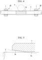
FIG. 4 is a cross-sectional view showing the oil-impregnated sintered bearing holding the rotary shaft. -
FIG. 5 is a main portion-enlarged cross-sectional view showing a main portion of the oil-impregnated sintered bearing in an enlarged manner. -
FIG. 6 is a cross-sectional view showing an oil-impregnated sintered bearing according to a third embodiment of the present invention. -
FIG. 7 is a cross-sectional view showing an oil-impregnated sintered bearing according to a fourth embodiment of the present invention. -
FIG. 8 is a graph showing results of an example. -
FIG. 9 is a graph showing results of an example. -
FIG. 10 is a graph showing results of an example. - Hereinafter, oil-impregnated sintered bearings that are embodiments to which the present invention is applied will be described with reference to drawings. The respective embodiments described below are specific descriptions for the better understanding of the invention, and, unless particularly otherwise described, the embodiments do not limit the present invention. In addition, drawings to be used in the following description show main portions in an enlarged or emphasized manner in some cases for convenience, and the dimensional ratios, angles, and the like of individual configurational elements are not always equal to those of actual cases.
- An oil-impregnated sintered bearing according to a first embodiment as shown in
FIG. 1 andFIG. 2 will be described. -
FIG. 1 is a cross-sectional view along a shaft direction of a rotary shaft which shows the oil-impregnated sintered bearing according to the first embodiment of the present invention.FIG. 2 is a cross-sectional view showing the oil-impregnated sintered bearing in a state in which the rotary shaft receives a load and is inclined. - In an oil-impregnated sintered bearing (hereinafter, simply referred to as the bearing) 10, a
bearing hole 3 into which arotary shaft 2 is scheduled to be inserted is formed inside a bearing main body (sintered body) 1 formed of a Fe-Cu-based sintered metal. - The bearing main body (sintered body) 1 is formed of a Fe-Cu-based sintered metal (Fe-Cu-based sintered body). Specifically, Fe powder and Cu powder including Cu-based flat raw material powder are introduced into a metal die having a core rod inserted into a cavity, and a Fe-Cu-based sintered body is shaped, thereby shaping the bearing
main body 1 including thebearing hole 3. - Areas occupied by a Cu phase in individual regions of the bearing
main body 1 described below can be varied by changing the mixing ratio between the Fe powder and the Cu powder including the Cu-based flat raw material powder separately for each of the regions. - The cross-sectional shape of the
bearing hole 3 in a surface orthogonal to a shaft line O in the longitudinal direction of therotary shaft 2 forms a circular shape, and the inner diameter of the bearing hole is set to be constant throughout the entire length along the shaft line O. In the present invention, in an inner circumferential surface S of thebearing hole 3, afirst region 3A forming a central portion along the shaft line O, asecond region 3B forming a first end portion 3A1 of thefirst region 3A through a first opening 3E1 of thebearing hole 3, and athird region 3C forming a second end portion 3A2 of thefirst region 3A through a second opening 3E2 of thebearing hole 3 are set. - In the present embodiment, the
first region 3A, thesecond region 3B, and thethird region 3C set in the friction surface (inner circumferential surface) S of thebearing hole 3 are set to evenly trisect the entire length of thebearing hole 3 along the shaft line O. Thefirst region 3A, thesecond region 3B, and thethird region 3C can be set to divide the entire length of thebearing hole 3 along the shaft line O at any proportions. - For example, in terms of the length along the shaft line O, it is possible to set the
first region 3A to be longest and set thesecond region 3B and thethird region 3C to be shorter than the first region or, conversely, it is possible to set thefirst region 3A to be shortest and set thesecond region 3B and thethird region 3C to be longer than the first region. - In addition, the
bearing hole 3 may not be provided with, particularly, thethird region 3C and may be only provided with thefirst region 3A and thesecond region 3B formed to bisect the friction surface (inner circumferential surface) S in a direction along the shaft line O. In this case, the first region is regarded as a region including the first opening of the bearing hole through the central portion, and the second region is regarded as a region covering the end portion opposite to the opening of the first region through the second opening of the bearing hole. - There is neither a clear compartment line nor a significant difference in composition between any two regions of the
first region 3A, thesecond region 3B, and thethird region 3C, and these regions are set for convenience to define the distributions of a Fe phase and the Cu phase along the shaft line O described below. - A friction surface S2 in the
second region 3B of thebearing hole 3 is formed so that the area of the Fe phase becomes larger and the area of the Cu phase becomes smaller than those in a friction surface S1 in thefirst region 3A. - For example, the area occupied by the Cu phase relative to the area of the entire friction surface S1 of the
first region 3A is set to 50% or more, and the area occupied by the Cu phase relative to the area of the entire friction surface S2 of thesecond region 3B is set to less than 50%. The area mentioned herein refers to an area excluding pores and cavities. - The area occupied by the Cu phase relative to the area of the entire friction surface S1 of the
first region 3A is more preferably 60% or more and less than 100%. In addition, the area occupied by the Cu phase relative to the area of the entire friction surface S2 of thesecond region 3B is more preferably 10% to 40%. - The area occupied by the Cu phase relative to the area of the entire friction surface S1 of the
first region 3A can be computed, for example, as described below. - First, a photograph of any places having a central portion 3AS along the shaft line O of the
first region 3A in the center is captured at a magnification of 200 times. A grid frame (for example, a 2 mm-grid frame with 30 cells × 40 cells) is overlaid on the captured photograph, and cells that are each occupied 50% or more by an iron matrix or a copper matrix are marked respectively. The total of the marked cells of the iron matrix and the copper matrix is regarded as the total number of marks, and the ratio of the cells of the copper matrix to the total number of marks is computed. In the present embodiment, the ratio of the cells of the copper matrix is computed as an area ratio of the Cu phase to the central portion 3AS along the shaft line O of thefirst region 3A. - The area ratio of the cells of the Cu phase to a central portion 3BS along the shaft line O of the
second region 3B can also be computed in the same manner. - In addition, the area of the Cu phase in the central portion 3BS along the shaft line O of the friction surface S2 of the
second region 3B is set to 20% or more and 70% or less and more preferably set to 30% or more and 60% or less of the area of the Cu phase to the central portion 3AS along the shaft line O of the friction surface S1 of thefirst region 3A. - In the
first region 3A and thesecond region 3B, the area ratios of the Cu phase to the unit areas of at least the friction surfaces that are the respective surfaces thereof need to be in the above-described ranges, and, furthermore, a region in which the above-described area ratios of the Cu phase are maintained may extend outwards in the radial direction from the surfaces in a predetermined thickness range. - In addition, in the
third region 3C, the area occupied by the Cu phase relative to the area of the entire friction surface S3 can be set to be, for example, approximately equal to or larger than that in thefirst region 3A. In addition, similar to thesecond region 3B, in thethird region 3C, the area of the Fe phase may be set to be larger and the area of the Cu phase may be set to be smaller than those in thefirst region 3A. - The bearing 10 having the above-described configuration is used in a state in which, for example, the bearing
main body 1 is impregnated with a lubricant and therotary shaft 2 is inserted into thebearing hole 3. When a relatively small torque is exerted to rotate therotary shaft 2, therotary shaft 2 seldom bends, and thus the surface of therotary shaft 2 is supported in contact with a friction surface (inner circumferential surface) S made up of thefirst region 3A, thesecond region 3B, and thethird region 3C of thebearing hole 3. In addition, on the friction surface (inner circumferential surface) S, the lubricant is caused to flow out from the inside of the bearingmain body 1 by a pumping action by the rotation of therotary shaft 2 and thermal expansion by friction heat, and the friction surface is lubricated. - In the friction surface S1 of the
first region 3A, the area of the Fe phase is smaller and the area of the Cu phase is larger than those in the friction surface S2 of thesecond region 3B, and thus, in a case where therotary shaft 2 comes into contact with a portion including thefirst region 3A without bending, it is possible to rotate therotary shaft 2 at a high speed (fast rotation). That is, the Cu component in the Fe-Cu-based sintered metal is suitable for an operation state in which the rotation speed of therotary shaft 2 is fast and the load being applied to therotary shaft 2 is low, and thus, even when therotary shaft 2 is rotated at a high speed, the function of the bearing is not impaired, and the durability also does not degrade. - On the other hand, when a large torque is transmitted to rotate the
rotary shaft 2, due to the bending of therotary shaft 2, the rotary shaft is shaft-supported with the shaft line inclined inside the bearingmain body 1. At this time, the surface of therotary shaft 2 comes into contact with thesecond region 3B of thebearing hole 3, and this portion is supported as the friction surface S2. In thesecond region 3B as well, similar to the straight hole portion, the lubricant is caused to flow out from the inside of the bearingmain body 1 by a pumping action by the rotation of therotary shaft 2 and thermal expansion by friction heat, and the friction surface is lubricated. - In the friction surface S2 of the
second region 3B of thebearing hole 3, the area of the Fe phase is larger and the area of the Cu phase is smaller than those in the friction surface S1 of thefirst region 3A, and thus, even in a case where therotary shaft 2 receives a large torque and bends, and therotary shaft 2 comes into contact with the friction surface S2 of thesecond region 3B, it is possible to stably rotate therotary shaft 2. That is, the Fe component in the Fe-Cu-based sintered metal is suitable for an operation state in which the rotation speed of therotary shaft 2 is slow and the load being applied to therotary shaft 2 is high, and thus, when the area of the Fe phase in the friction surface S2 of thesecond region 3B of thebearing hole 3 is increased to be larger than that in the friction surface S1 of thefirst region 3A, it becomes possible to stably rotate therotary shaft 2 even when therotary shaft 2 receives a high load and bends, the function of the bearing is not impaired, and the durability also does not degrade. - Due to the above-described actions, the bearing 10 capable of exhibiting the bearing performance to the maximum extent in each of the fast rotation and low load state and the slow rotation and high load state of the
rotary shaft 2 can be realized. - An oil-impregnated sintered bearing according to a second embodiment as shown in
FIG. 3 to FIG. 5 will be described. -
FIG. 3 is a cross-sectional view along a shaft direction of a rotary shaft which shows the oil-impregnated sintered bearing according to the second embodiment of the present invention. In addition,FIG. 4 is a cross-sectional view showing a state in which the rotary shaft is held in the oil-impregnated sintered bearing shown inFIG. 3 . In addition,FIG. 5 is a main portion-enlarged view showing a contact state between the oil-impregnated sintered bearing and the rotary shaft. - In an oil-impregnated sintered bearing (hereinafter, simply referred to as the bearing) 20, a
bearing hole 4 into which therotary shaft 2 is scheduled to be inserted is formed inside the bearing main body (sintered body) 1 formed of a Fe-Cu-based sintered metal. - The cross-sectional shape of the
bearing hole 4 in a surface orthogonal to the shaft line O in the longitudinal direction of therotary shaft 2 forms a circular shape, and, on a friction surface (inner circumferential surface) S of thebearing hole 4, afirst region 4A forming a central portion along the shaft line O, asecond region 4B forming a first end portion 4A1 of thefirst region 4A through a first opening 4E1 of thebearing hole 4, and athird region 4C forming a second end portion 4A2 of thefirst region 4A through a second opening 4E2 of thebearing hole 4 are set. - In the present embodiment, the
first region 4A, thesecond region 4B, and thethird region 4C set in the inner circumferential surface S of thebearing hole 4 are set to evenly trisect the entire length of thebearing hole 4 along the shaft line O. Thefirst region 4A, thesecond region 4B, and thethird region 4C can be set to divide the entire length of thebearing hole 4 along the shaft line O at any proportions. - In the
first region 4A set on the friction surface (inner circumferential surface) S of thebearing hole 4, astraight hole portion 4a having a diameter that is slightly larger than the diameter of therotary shaft 2 and having a diameter that is constant at any location in the longitudinal direction is formed. In addition, in thesecond region 4B and thethird region 4C, a firstdiameter expansion portion 4b and a seconddiameter expansion portion 4c that are provided continuously from thestraight hole portion 4a on both sides in the longitudinal direction respectively, have a diameter that monotonously increases outwards, and form a tapered shape are formed respectively. In both of the firstdiameter expansion portion 4b and the seconddiameter expansion portion 4c, an angle (taper angle) θ1 formed by an inclined surface of the diameter expansion portion and an inner surface of thestraight hole portion 4a (or the shaft line O of the rotary shaft 2) parallel to the shaft direction of the bearingmain body 1 is set to any angles, for example, approximately 0.1° to 10°. This angle is preferably set in accordance with the bending angle of a shaft that is scheduled to be a sliding object. InFIG. 3 , the angle is shown in the drawing in an exaggerated manner in order to clarify θ1. - When the bearing
main body 1 is seen on a cross section along the shaft line O of the rotary shaft 2 (refer toFIG. 3 ), regarding the twodiameter expansion portions straight hole portion 4a, a straight line L1a extended from the inclined surface of the firstdiameter expansion portion 4b in an inclination direction toward the center of the bearingmain body 1 and a straight line L1b extended from the inclined surface of the seconddiameter expansion portion 4c located at the opposite corner in an inclination direction toward the center of the bearingmain body 1 are disposed parallel to each other, and an interval d1 between both straight lines L1a and L1b is slightly larger than a diameter D of therotary shaft 2 and almost equal to an inner diameter of thestraight hole portion 4a. - In other words, the straight line L1a extended from the inclined surface on an upper end side of the first
diameter expansion portion 4b in the inclination direction toward the center of the bearingmain body 1 and the straight line L1b extended from the inclined surface on a lower end side of the seconddiameter expansion portion 4c in the inclination direction toward the center of the bearingmain body 1 have a parallel relationship, and the interval d1 between both straight lines L1a and L1b is slightly larger than the diameter D of therotary shaft 2 and almost equal to the inner diameter of thestraight hole portion 4a. - The entire bearing main body (sintered body) 1 is formed of a Fe-Cu-based sintered metal (Fe-Cu-based sintered body). Specifically, Fe powder and Cu powder formed of Cu powder including Cu-based flat raw material powder are introduced to a shaping die, a Fe-Cu-based sintered body including a through-hole is formed, and the diameter of the through- hole in the sintered body is expanded up to a predetermined depth on both sides by sizing, thereby forming the bearing
main body 1 including thestraight hole portion 4a and thediameter expansion portions - The first
diameter expansion portion 4b is formed so that, in the friction surface (inner circumferential surface) S forming the surface of the first diameter expansion portion which comes into contact with therotary shaft 2, the area of a Fe phase configuring the Fe-Cu-based sintered metal becomes larger and the area of a Cu phase becomes smaller than those in the friction surface of thestraight hole portion 4a. - For example, the area occupied by the Cu phase relative to the area of the entire friction surface S2 of the first
diameter expansion portion 4b is set to less than 50%. In addition, the area occupied by the Cu phase relative to the area of the entire friction surface of thestraight hole portion 4a is set to 50% or more. - The area occupied by the Cu phase relative to the area of the entire friction surface S2 of the first
diameter expansion portion 4b is more preferably 10% to 40%. In addition, the area occupied by the Cu phase relative to the area of the entire friction surface of thestraight hole portion 4a is more preferably 60% to less than 100%. - In addition, the area of the Cu phase in a central portion 4BS along the shaft direction (shaft line O) of the friction surface of the first
diameter expansion portion 4b is set to 20% or more and 90% or less and more preferably 30% or more and 60% or less of the area of the Cu phase in a central portion 4AS along the shaft direction of the friction surface of thestraight hole portion 4a. - The areas of the Fe phase and the Cu phase can be made to differ in the
straight hole portion 4a and the firstdiameter expansion portion 4b as described above by, in the formation of the sintered body made of the Fe-Cu-based sintered metal, selectively collecting Cu near the surface of the metal die wall by moving the metal die during the introduction of the Fe powder and the Cu powder formed of Cu powder including Cu-based flat raw material powder which are raw materials to the shaping die. - In the
straight hole portion 4a and the firstdiameter expansion portion 4b, the area ratios of the Fe phase and the Cu phase need to differ in at least the friction surfaces that are the respective surfaces thereof, and, furthermore, regions in which the area ratios of the Fe phase and the Cu phase differ may extend from the respective friction surfaces toward the center in the radial direction in a predetermined thickness. - In addition, in the second
diameter expansion portion 4c, the area occupied by the Cu phase relative to the area of the entire friction surface S3 can be set to be, for example, approximately equal to or larger than that in thestraight hole portion 4a. - The bearing 20 having the above-described configuration is used in a state in which, for example, the bearing
main body 1 is impregnated with a lubricant and therotary shaft 2 is inserted into thebearing hole 3.FIG. 4 shows an example of a mechanism that is configured to support therotary shaft 2 at two places using the bearings. In this mechanism, ascrew gear 2a is formed on a circumferential surface of therotary shaft 2, both ends of therotary shaft 2 are supported by the bearings, ascrew gear 5 that is configured to be rotary-driven by a driving device, not shown, is engaged with thescrew gear 2a on therotary shaft 2 side, and therotary shaft 2 is rotated by rotating thescrew gear 5. In actual cases, therotary shaft 2 does not bend as much as shown inFIG. 4 ; however, here, the bending is shown in an exaggerated manner in order to clarify the gist of the description. - When a relatively small torque is exerted to rotate the
rotary shaft 2, therotary shaft 2 seldom bends, and thus the surface of therotary shaft 2 comes into contact with thestraight hole portion 4a, and this portion is supported as the friction surface S1. In thestraight hole portion 4a, the lubricant is caused to flow out from the inside of the bearingmain body 1 by a pumping action by the rotation of therotary shaft 2 and thermal expansion by friction heat, and the friction surface S1 is lubricated. - In the friction surface S1 of the
straight hole portion 4a, the area of the Fe phase is smaller and the area of the Cu phase is larger than those in the friction surface S2 of the firstdiameter expansion portion 4b, and thus, in a case where therotary shaft 2 comes into contact with thestraight hole portion 4a without bending, it is possible to rotate therotary shaft 2 at a high speed (fast rotation). That is, the Cu component in the Fe-Cu-based sintered metal is suitable for an operation state in which the rotation speed of therotary shaft 2 is fast and the load being applied to therotary shaft 2 is low, and thus, when the area of the Cu phase in thestraight hole portion 4a is increased relative to the firstdiameter expansion portion 4b, the function of the bearing is not impaired, and the durability also does not degrade even when therotary shaft 2 is rotated at a high speed. - On the other hand, when a large torque is transmitted to rotate the
rotary shaft 2, a shear load exerted on therotary shaft 2 is high, therotary shaft 2 is strongly vibrated, and misalignment is likely to occur. At this time, the vibration generated in therotary shaft 2 causes the lubricant that lubricates therotary shaft 2 and thestraight hole portion 4a to be pushed out toward the firstdiameter expansion portion 4b and loaded into the space between therotary shaft 2 and the firstdiameter expansion portion 4b. The lubricant loaded into the space between therotary shaft 2 and the firstdiameter expansion portion 4b is pressurized by the vibration of therotary shaft 2 so as to be pressed against the firstdiameter expansion portion 4b, but the firstdiameter expansion portion 4b has been formed to be dense, and thus the lubricant is not pressed into the inside of the bearingmain body 1, instead, remains between therotary shaft 2 and the firstdiameter expansion portion 4b, and exerts a repulsive force on therotary shaft 2. This repulsive force suppresses the vibration of therotary shaft 2 and prevents the misalignment of therotary shaft 2 relative to the bearing. - However, in a case where the shear load exerted on the
rotary shaft 2 is extremely high and the push-back action of the lubricant remaining between therotary shaft 2 and the firstdiameter expansion portion 4b does not sufficiently function, therotary shaft 2 is shaft-supported with the shaft line inclined inside the bearingmain body 1. At this time, the surface of therotary shaft 2 comes into contact with the firstdiameter expansion portion 4b, and this portion is supported as the friction surface S2. In the firstdiameter expansion portion 4b as well, similar to thestraight hole portion 4a, the lubricant is caused to flow out from the inside of the bearingmain body 1 by a pumping action by the rotation of therotary shaft 2 and thermal expansion by friction heat, and the friction surface S2 is lubricated. - In the friction surface S2 of the first
diameter expansion portion 4b, the area of the Fe phase is larger and the area of the Cu phase is smaller than those in the friction surface S1 of thestraight hole portion 4a, and thus, even in a case where therotary shaft 2 receives a large torque, bends, and comes into contact with the firstdiameter expansion portion 4b, it is possible to stably rotate therotary shaft 2. That is, the Fe component in the Fe-Cu-based sintered metal is suitable for an operation state in which the rotation speed of therotary shaft 2 is slow and the load being applied to therotary shaft 2 is high, and thus, when the area of the Fe phase in the firstdiameter expansion portion 4b is increased to be larger than that in thestraight hole portion 4a, it becomes possible to stably rotate therotary shaft 2 even when therotary shaft 2 receives a high load and bends, the function of the bearing is not impaired, and the durability also does not degrade. - In the present embodiment, in the friction surface of the first
diameter expansion portion 4b, the area of the Fe phase is set to be larger and the area of the Cu phase is set to be smaller than those in the friction surface of thestraight hole portion 4a. Generally, in a configuration as shown inFIG. 4 , in a case where a large torque is exerted on a vicinity of the center of therotary shaft 2 and the rotary shaft bends, therotary shaft 2 is more strongly pressed against the portion closer to the center of therotary shaft 2, that is, the firstdiameter expansion portion 4b than the seconddiameter expansion portion 4c. Therefore, it is also effective to configure only the firstdiameter expansion portion 4b so as to have a larger area of the Fe phase and a smaller area of the Cu phase than those in thestraight hole portion 4a. - In addition, the areas of the Fe phase may be set to be larger and the areas of the Cu phase may be set to be smaller in both the first
diameter expansion portions 4b and the seconddiameter expansion portions 4c of thebearings rotary shaft 2 than those in thestraight hole portion 4a. - An oil-impregnated sintered bearing according to a third embodiment as shown in
FIG. 6 will be described. -
FIG. 6 is a cross-sectional view along a shaft direction of a rotary shaft showing the oil-impregnated sintered bearing according to the third embodiment of the present invention. - In a
bearing 30 shown inFIG. 6 , a bearinghole 13 formed inside the bearing main body (sintered body) 11 formed of a sintered metal has a circular shape as the cross-sectional shape in a surface orthogonal to the shaft line O in the longitudinal direction of therotary shaft 2 and includes astraight hole portion 13a that is present in almost the center of the bearingmain body 11, has a diameter that is slightly larger than the diameter of therotary shaft 2, and has a diameter that is constant at any location in the longitudinal direction and a firstdiameter expansion portion 13b and a seconddiameter expansion portion 13c that are provided continuously from thestraight hole portion 13a on both sides in the longitudinal direction respectively. - The first
diameter expansion portion 13b and the seconddiameter expansion portion 13c are made up of first diameter expansion regions 13b1 and 13c1 and second diameter expansion regions 13b2 and 13c2 respectively which have taper angles relative to an inner surface of thestraight hole portion 13a (or the shaft line O of the rotary shaft 2) parallel to the shaft direction of the bearingmain body 1 that are varied stepwise. Taper angles θ2 of the second diameter expansion regions 13b2 and 13c2 present at locations far from thestraight hole portion 13a are formed to be larger than taper angles θ1 of the first diameter expansion regions 13b1 and 13c1. - When the bearing
main body 11 is seen on a cross section along the shaft line O of the rotary shaft 2 (refer toFIG. 6 ), regarding the two second diameter expansion regions 13b2 and 13c2 present outside the first diameter expansion regions 13b1 and 13c1, an interval d2 between a straight line L2b extended from the inclined surface of the second diameter expansion region 13b2 of the firstdiameter expansion portion 13b toward the center of the bearingmain body 1 and a straight line L2a extended from the inclined surface of the second diameter expansion region 13c2 of the seconddiameter expansion portion 13c located at the opposite corner toward the center of the bearingmain body 11 is larger than the diameter D of therotary shaft 2 and almost equal to an inner diameter of thestraight hole portion 13a. - In other words, the straight line L2b extended from the inclined surface on a lower end side of the second diameter expansion region 13b2 of the first
diameter expansion portion 13b in an inclination direction toward the center of the bearingmain body 1 and the straight line L2a extended from the inclined surface on an upper end side of the second diameter expansion region 13c2 of the seconddiameter expansion portion 13c in an inclination direction toward the center of the bearingmain body 11 have a parallel relationship, and the interval d2 between both straight lines L2b and L2a is slightly larger than the diameter D of therotary shaft 2 and almost equal to the inner diameter of thestraight hole portion 13a. - The entire bearing
main body 11 is formed of a Fe-Cu-based sintered metal. Specifically, Fe powder and Cu powder formed of Cu powder including Cu-based flat raw material powder are introduced to a shaping die, a Fe-Cu-based sintered body including a through-hole is formed, and the diameter of the through-hole in the sintered body is expanded up to a predetermined depth on both sides by sizing, thereby forming the bearingmain body 11 including thestraight hole portion 13a and thediameter expansion portions - The first
diameter expansion portion 13b is formed so that, in the friction surface S2 forming the surface of the first diameter expansion portion which comes into contact with therotary shaft 2, the area of a Fe phase configuring the Fe-Cu-based sintered metal becomes larger and the area of a Cu phase becomes smaller than those in the friction surface S1 of thestraight hole portion 13a. - For example, the area occupied by the Cu phase relative to the area of the entire friction surface of the first
diameter expansion portion 13b is set to less than 50%. In addition, the area occupied by the Cu phase relative to the area of the entire friction surface of thestraight hole portion 13a is set to 50% or more. - The area occupied by the Cu phase relative to the area of the entire friction surface of the first
diameter expansion portion 13b is more preferably 10% to 40%. In addition, the area occupied by the Cu phase relative to the area of the entire friction surface of thestraight hole portion 13a is more preferably 60% to less than 100%. - In the above-described
bearing 30, in a case where the degree of the torque that is transmitted to therotary shaft 2 varies, the amount of bending of therotary shaft 2 changes in proportion to the degree of the torque, and the inclination angle of therotary shaft 2 inside the bearing also changes. In the above-described bearing, when therotary shaft 2 is rotated by transmitting a relatively small torque, therotary shaft 2 bends slightly and the surface of therotary shaft 2 comes into contact with the first diameter expansion region 13b1 having a small taper angle. In addition, when therotary shaft 2 is rotated by transmitting a large torque, therotary shaft 2 bends significantly and the surface of therotary shaft 2 comes into contact with the second diameter expansion region 13b2 having a large taper angle. - In the friction surface S2 of the first
diameter expansion portion 13b, the area of the Fe phase is larger and the area of the Cu phase is smaller than those in the friction surface S1 of thestraight hole portion 13a, and thus, even in a case where therotary shaft 2 receives a large torque and bends and the surface of therotary shaft 2 comes into contact with the first diameter expansion region 13b1 or the second diameter expansion region 13b2, it is possible to stably rotate therotary shaft 2. That is, the Fe component in the Fe-Cu-based sintered metal is suitable for an operation state in which the rotation speed of therotary shaft 2 is slow and the load being applied to therotary shaft 2 is high, and thus, when the area of the Fe phase in the firstdiameter expansion portion 13b is increased to be larger than that in thestraight hole portion 13a, it becomes possible to stably rotate therotary shaft 2 even when therotary shaft 2 receives a high load and bends, the function of the bearing is not impaired, and the durability also does not degrade. - An oil-impregnated sintered bearing according to a fourth embodiment as shown in
FIG. 7 will be described. -
FIG. 7 is a cross-sectional view along a shaft direction of a rotary shaft showing the oil-impregnated sintered bearing according to the fourth embodiment of the present invention. - In a
bearing 40 of the present embodiment, a firstdiameter expansion portion 23b is provided only on a first side of astraight hole portion 23a, and a chamfered portion (second diameter expansion portion) 23d is provided on a second side of thestraight hole portion 23a. The chamferedportion 23d is provided to facilitate the passing of therotary shaft 2 mainly through thestraight hole portion 23a and thus does not come into contact with therotary shaft 2 regardless of how therotary shaft 2 is dislocated from the bearingmain body 30. This is because the chamfer angle of the chamferedportion 23d is greater than the inclination angle θ1 of the firstdiameter expansion portion 23b. - Furthermore, when a bearing main body (sintered body) 12 is seen on a cross section along the shaft line O of the
rotary shaft 2, regarding thestraight hole portion 23a and the firstdiameter expansion portion 23b, an interval d2 (corresponding to the length of a perpendicular line drawn from a straight line L1a extended from the inclined surface of the firstdiameter expansion portion 23b in an inclination direction toward the center of the bearingmain body 12 to a terminal portion of thestraight hole portion 23a that is farthest from thediameter expansion portion 23b) between the straight line L1a and a friction surface (inner circumferential surface) S1 of thestraight hole portion 23a that faces an inclined friction surface (inner circumferential surface) S2 of the firstdiameter expansion portion 23b across the center of the bearingmain body 12 is slightly larger than the diameter D of therotary shaft 2 and almost equal to an inner diameter of the firststraight hole portion 23a. - In other words, when the straight line L1a extended from the inclined surface of the first
diameter expansion portion 23b in the inclination direction toward the center of the bearingmain body 12 on an upper end side of the bearing main body (sintered body) 12 is imagined, the interval between the terminal portion of thestraight hole portion 23a and the straight line L1a when a perpendicular line is extended from the terminal portion of thestraight hole portion 23a that is on a lower end side of the bearing main body (sintered body) 12 and is connected with the chamferedportion 23d toward the straight line L1a is regarded as d2. - In the bearing having the above-described configuration, in a case where the shear load exerted on the
rotary shaft 2 is extremely high and the push-back action of a lubricant remaining between therotary shaft 2 and thediameter expansion portion 23b does not sufficiently function, therotary shaft 2 bends and is supported by the firstdiameter expansion portion 23b of the bearingmain body 12. - In the present embodiment as well, the entire bearing
main body 12 is formed of a Fe-Cu-based sintered metal, and the firstdiameter expansion portion 23b is formed so that, in the friction surface S2 forming the surface of the first diameter expansion portion which comes into contact with therotary shaft 2, the area of a Fe phase configuring the Fe-Cu-based sintered metal becomes larger and the area of a Cu phase becomes smaller than those in the friction surface S1 of thestraight hole portion 23a. - For example, the area occupied by the Cu phase relative to the area of the entire friction surface S2 of the
diameter expansion portion 23b is set to less than 50%. In addition, the area occupied by the Cu phase relative to the area of the entire friction surface S1 of thestraight hole portion 23a is set to 50% or more. - The area occupied by the Cu phase relative to the area of the entire friction surface S2 of the
diameter expansion portion 23b is more preferably 10% to 40%. In addition, the area occupied by the Cu phase relative to the area of the entire friction surface S1 of thestraight hole portion 23a is more preferably 60% to less than 100%. - As described above, in the friction surface S2 of the first
diameter expansion portion 23b, the area of the Fe phase is larger and the area of the Cu phase is smaller than those in the friction surface S1 of thestraight hole portion 23a, and thus, even in a case where therotary shaft 2 receives a large torque and bends and the surface of therotary shaft 2 comes into contact with the firstdiameter expansion portion 23b, it is possible to stably rotate therotary shaft 2. That is, the Fe component in the Fe-Cu-based sintered metal is suitable for an operation state in which the rotation speed of therotary shaft 2 is slow and the load being applied to therotary shaft 2 is high, and thus, when the area of the Fe phase in the firstdiameter expansion portion 23b is increased to be larger than that in thestraight hole portion 23a, it becomes possible to stably rotate therotary shaft 2 even when therotary shaft 2 receives a high load and bends, the function of the bearing is not impaired, and the durability also does not degrade. - In addition to the above-described embodiments, it is also possible to set the taper angle relative to the shaft direction of a first diameter expansion portion of the diameter expansion portions respectively provided on both sides of the straight hole portion to be smaller than the taper angle relative to the shaft direction of a second diameter expansion portion. Even in such an embodiment, the bearing main body (sintered body) is formed of a Fe-Cu-based sintered metal, and either or both diameter expansion portions are formed so that, in the friction surface(s) of at least one diameter expansion portion or the first and second diameter expansion portions, the area of the Fe phase configuring the Fe-Cu-based sintered metal becomes larger and the area of the Cu phase becomes smaller than those in the friction surface of the straight hole portion.
- Hitherto, several embodiments of the present invention have been described, but these embodiments have been presented as examples and do not intend to limit the scope of the invention. These embodiments can also be carried out in a variety of other forms and can be omitted, substituted, or modified in various manners within the scope the invention defined by the appended claims.
- A preferred ratio of the area ratio occupied by the Cu phase relative to the area of the inner circumferential surface S in the
first region 3A in the oil-impregnated sintered bearing 10 of the first embodiment shown inFIG. 1 was verified. - In the verification, oil-impregnated
sintered bearings 10 assamples 1 to 4 shown in Table 1 below in which the area ratios of the Cu phase relative to the area of the inner circumferential surface S in thefirst region 3A were changed respectively were produced. - The
sample 1 was obtained by using a powder mixture in which the entire mixing ratio was set to Fe-15 wt% Cu-2 wt% Sn, changing the blending ratio of Cu in the respective regions, introducing the powder mixture into a metal die, and sintering the powder mixture. Thesample 2 was obtained by using a powder mixture in which the entire mixing ratio was set to Fe-20 wt% Cu-2 wt% Sn, changing the blending ratio of Cu in the respective regions, introducing the powder mixture into a metal die, and sintering the powder mixture. Thesample 3 was obtained by using a powder mixture in which the entire mixing ratio was set to Fe-10 wt% Cu-1 wt% Sn, changing the blending ratio of Cu in the respective regions, introducing the powder mixture into a metal die, and sintering the powder mixture. Thesample 4 was obtained by using a powder mixture in which the entire mixing ratio was set to Fe-1 wt% Cu-0.5 wt% Sn, changing the blending ratio of Cu in the respective regions, introducing the powder mixture into a metal die, and sintering the powder mixture. - The area ratios of the Cu phase relative to the areas of the inner circumferential surface S in the
first regions 3A of the oil-impregnatedsintered bearings 10 as the obtainedsamples 1 to 4 were - The area ratios occupied by the Cu phase relative to the area of the inner circumferential surface S were obtained using the method described in the embodiment.
[Table 1] Area ratio of Cu phase Sample 1 0.5 Sample 20.6 Sample 30.25 Sample 40 - For the
respective samples 1 to 4 described above, the friction coefficients were measured. In the measurement, a sliding test was carried out by rotating therotary shaft 2 in a state in which a load was applied to the location of the central portion 3AS along the shaft line O of thefirst region 3A in the oil-impregnated sintered bearing 10 shown inFIG. 1 , and the friction coefficient was computed. The measurement conditions are as described below. - 1. Circumferential speed of rotary shaft 2: 100 m/min
- 2. Load: 1 MPa
- 3. Measurement environment temperature: Room temperature
- 4. Rotation time: 1800 seconds
- The results of the verification example 1 carried out under the above-described conditions are shown in Table 2 and
FIG. 8 .[Table 2] Friction coefficient Sample 1 0.115 Sample 20.110 Sample 30.139 Sample 40.155 - According to the results of the verification example 1 shown in Table 2 and
FIG. 8 , it was confirmed that the friction coefficients of thesample 1 and thesample 2 were significantly lower than those of thesample 3 and thesample 4 and a strong effect of decreasing the friction coefficient could be obtained by setting the area ratio occupied by the Cu phase relative to the area of the inner circumferential surface S in thefirst region 3A of the oil-impregnated sintered bearing 10 shown inFIG. 1 to 50% or more. - A preferred ratio of the area ratio occupied by the Cu phase relative to the area of the inner circumferential surface S in the
first region 3A (the first region (A) in Table 3) in the oil-impregnated sintered bearing 10 of the first embodiment shown inFIG. 1 was verified. - In the verification, oil-impregnated
sintered bearings 10 assamples 5 to 9 shown in Table 3 below in which the area ratios of the Cu phase relative to the area of the inner circumferential surface S in thesecond region 3B (the second region (B) in Table 3) were changed respectively were produced. - The
sample 5 was obtained by using a powder mixture in which the entire mixing ratio was set to Fe-60 wt% Cu-3 wt% Sn, changing the blending ratio of Cu in the respective regions, introducing the powder mixture into a metal die, and sintering the powder mixture. The sample 6 was obtained by using a powder mixture in which the entire mixing ratio was set to Fe-20 wt% Cu-2 wt% Sn, changing the blending ratio of Cu in the respective regions, introducing the powder mixture into a metal die, and sintering the powder mixture. The sample 7 was obtained by using a powder mixture in which the entire mixing ratio was set to Fe-25 wt% Cu-2 wt% Sn, changing the blending ratio of Cu in the respective regions, introducing the powder mixture into a metal die, and sintering the powder mixture. The sample 8 was obtained by using a powder mixture in which the entire mixing ratio was set to Fe-18 wt% Cu-2 wt% Sn, changing the blending ratio of Cu in the respective regions, introducing the powder mixture into a metal die, and sintering the powder mixture. The sample 9 was obtained by using a powder mixture in which the entire mixing ratio was set to Fe-1 wt% Cu-0.5 wt% Sn, changing the blending ratio of Cu in the respective regions, introducing the powder mixture into a metal die, and sintering the powder mixture. - The area ratios occupied by the Cu phase relative to the area of the inner circumferential surface S were obtained using the method described in the embodiment.
[Table 3] First region (A) Second region (B) [(B)/(A)] × 100 Sample 50.9 0.9 100% Sample 6 0.6 0.3 50% Sample 7 0.7 0.4 57% Sample 8 0.6 0.2 33% Sample 9 0 0 0% - For the
respective samples 5 to 9 described above, the friction coefficients and the abrasion amounts were measured. In the measurement, a sliding test was carried out by rotating therotary shaft 2 in a state in which a load was applied to alocation 2 mm offset from the central portion 3AS along the shaft line O of thefirst region 3A in the oil-impregnated sintered bearing 10 shown inFIG. 1 , and the friction coefficient was computed. The measurement conditions are as described below. - 1. Circumferential speed of rotary shaft 2: 25 m/min
- 2. Load: 5 MPa
- 3. Measurement environment temperature: Room temperature
- 4. Rotation time: 1800 seconds
- The abrasion amounts were measured using a cylinder gauge.
- The results of the verification example 2 carried out under the above-described conditions are shown in Table 4 and
FIG. 9 .[Table 4] Friction coefficient Abrasion amount (mm) Sample 50.23 0.012 Sample 6 0.241 0.005 Sample 7 0.24 0.006 Sample 8 0.246 0.004 Sample 9 0.26 0.003 - According to the results of the verification example 2 shown in Table 4 and
FIG. 9 , as the area occupied by the Cu phase increases, the friction coefficient decreases, and the friction resistance can be decreased. On the other hand, it was confirmed that, as the area occupied by the Cu phase decreases, the abrasion resistance further improves. - In the oil-impregnated sintered bearing 20 of the second embodiment shown in
FIG. 3 , the ratio between the area occupied by the Cu phase in thestraight hole portion 4a forming thefirst region 4A (the first region (A) in Table 5) and the area occupied by the Cu phase in the firstdiameter expansion portion 4b forming thesecond region 4B (the second region (B) in Table 5), and the relationship between the friction coefficient and the abrasion amount were verified. - In the verification, oil-impregnated
sintered bearings 20 assamples 10 to 12 shown in Table 5 below in which the area ratios between the Cu phases in thestraight hole portions 4a and the Cu phases in the firstdiameter expansion portions 4b were changed respectively were produced. - The
sample 10 was obtained by using a powder mixture in which the entire mixing ratio was set to Fe-20 wt% Cu-2 wt% Sn, changing the blending ratio of Cu in the respective regions, introducing the powder mixture into a metal die, and sintering the powder mixture. Thesample 11 was obtained by using a powder mixture in which the entire mixing ratio was set to Fe-25 wt% Cu-2 wt% Sn, changing the blending ratio of Cu in the respective regions, introducing the powder mixture into a metal die, and sintering the powder mixture. Thesample 12 was obtained by using a powder mixture in which the entire mixing ratio was set to Fe-18 wt% Cu-2 wt% Sn, changing the blending ratio of Cu in the respective regions, introducing the powder mixture into a metal die, and sintering the powder mixture. - The area ratios occupied by the Cu phase relative to the area of the inner circumferential surface S were obtained using the method described in the embodiment.
[Table 5] First region (A) Second region (B) [(B)/(A)] × 100 Sample 110.6 0.3 50 % Sample 12 0.7 0.4 57 % Sample 13 0.6 0.2 33% - For the
respective samples 10 to 12 described above, the friction coefficients and the abrasion amounts were measured. In the measurement, a sliding test was carried out by rotating therotary shaft 2 in a state in which, in the oil-impregnated sintered bearing 20 shown inFIG. 3 , a load was applied so that the rotary shaft was offset from the central portion 4AS along the shaft line O of thefirst region 4A and slidden in thediameter expansion portions - 1. Circumferential speed of rotary shaft 2: 25 m/min
- 2. Load: 5 MPa
- 3. Measurement environment temperature: Room temperature
- 4. Rotation time: 1800 seconds
- The abrasion amounts were measured using a cylinder gauge.
- The results of the verification example 3 carried out under the above-described conditions are shown in Table 6 and
FIG. 10 .[Table 6] Friction coefficient Abrasion amount (mm) Sample 110.231 0.004 Sample 120.22 0.004 Sample 130.236 0.005 - According to the results of the verification example 3 shown in Table 6 and
FIG. 10 , it was confirmed that, in a case where therotary shaft 2 is rotated so as to be inclined, the friction coefficient can be decreased by increasing the area occupied by the Cu phase in the firstdiameter expansion portion 4b which therotary shaft 2 comes into contact with. -
- 1,11,12
- BEARING MAIN BODY (SINTERED BODY)
- 2
- ROTARY SHAFT
- 4a, 13a, 23a
- STRAIGHT HOLE PORTION
- 4b, 13b, 23b
- FIRST DIAMETER EXPANSION PORTION
- 4c, 13c, 23d
- SECOND DIAMETER EXPANSION PORTION
- 10, 20, 30, 40
- OIL-IMPREGNATED SINTERED BEARING (BEARING)
Claims (8)
- An oil-impregnated sintered bearing (10, 20, 30 or 40) in which a Fe-Cu-based sintered body (1) is impregnated with a lubricant, comprising:a bearing hole (3 or 4) that is configured to support a rotary shaft (2) inserted therethrough,wherein an inner circumferential surface (S) of the bearing hole (3 or 4) includes at least a first region (3A or 4A) including a central portion (3AS or 4AS) in a shaft direction and a second region (3B or 4B) forming a portion from a first end portion (3A1 or 4A1) of the first region (3A or 4A) to a first opening (3E1 or 4E1) of the bearing hole (3 or 4), characterized in thatin a friction surface of the second region (3B or 4B), an area of a Fe phase is larger and an area of a Cu phase formed of Cu powder including Cu-based flat raw material powder is smaller than those in a friction surface of the first region (3A or 4A).
- The oil-impregnated sintered bearing (10, 20, 30 or 40) according to Claim 1,
wherein an area occupied by the Cu phase relative to an area of the entire friction surface of the first region (3A or 4A) is 50% or more, and an area occupied by the Cu phase relative to an area of the entire friction surface of the second region (3B or 4B) is less than 50%. - The oil-impregnated sintered bearing (10, 20, 30 or 40) according to Claim 1,
wherein an area of the Cu phase in a central portion (3BS or 4BS) of the friction surface of the second region (3B or 4B) along the shaft direction is 20% or more and 70% or less of an area of the Cu phase in a central portion (3AS or 4AS) of the friction surface of the first region (3A or 4A) along the shaft direction. - The oil-impregnated sintered bearing (10, 20, 30 or 40) according to any one of Claims 1 to 3,
wherein the inner circumferential surface (S) of the bearing hole (3 or 4) further includes a third region (3C or 4C) forming a portion from a second end portion (3A2 or 4A2) of the first region (3A or 4A) to a second opening (3E2 or 4E2) of the bearing hole (3 or 4). - The oil-impregnated sintered bearing (20) according to any one of Claims 1 to 4,
wherein the bearing hole (4) includes a straight hole portion (4a) that is formed in the first region (4A) and has a constant diameter and a first diameter expansion portion (4b) that is formed in the second region (4B), continues from the straight hole portion (4a), and has a diameter that increases outwards, to form a tapered shape. - The oil-impregnated sintered bearing (20) according to Claim 5,
wherein the bearing hole (4) further includes a second diameter expansion portion (4c) that is formed in the third region (4C), continues from the straight hole portion (4a), and has a diameter that increases outwards, to form a tapered shape. - The oil-impregnated sintered bearing (20) according to Claim 6,
wherein a taper angle (θ1) of the first diameter expansion portion (4b) relative to the shaft direction is equal to a taper angle (θ1) of the second diameter expansion portion (4c) relative to the shaft direction. - The oil-impregnated sintered bearing (20) according to Claim 6,
wherein a taper angle (θ1) of the first diameter expansion portion (4b) relative to the shaft direction is different from a taper angle (θ2) of the second diameter expansion portion (4c) relative to the shaft direction.
Applications Claiming Priority (2)
| Application Number | Priority Date | Filing Date | Title |
|---|---|---|---|
| JP2016209695 | 2016-10-26 | ||
| PCT/JP2017/038745 WO2018079670A1 (en) | 2016-10-26 | 2017-10-26 | Oil-impregnated sintered bearing |
Publications (3)
| Publication Number | Publication Date |
|---|---|
| EP3534023A1 EP3534023A1 (en) | 2019-09-04 |
| EP3534023A4 EP3534023A4 (en) | 2020-07-22 |
| EP3534023B1 true EP3534023B1 (en) | 2022-01-26 |
Family
ID=62025124
Family Applications (1)
| Application Number | Title | Priority Date | Filing Date |
|---|---|---|---|
| EP17863566.0A Active EP3534023B1 (en) | 2016-10-26 | 2017-10-26 | Oil-impregnated sintered bearing |
Country Status (5)
| Country | Link |
|---|---|
| US (1) | US10865828B2 (en) |
| EP (1) | EP3534023B1 (en) |
| JP (1) | JP6900389B2 (en) |
| CN (1) | CN109844335B (en) |
| WO (1) | WO2018079670A1 (en) |
Families Citing this family (1)
| Publication number | Priority date | Publication date | Assignee | Title |
|---|---|---|---|---|
| CN111919041B (en) * | 2018-03-12 | 2022-04-19 | 日产自动车株式会社 | Bearing component |
Family Cites Families (17)
| Publication number | Priority date | Publication date | Assignee | Title |
|---|---|---|---|---|
| JPH0819941B2 (en) | 1987-07-23 | 1996-03-04 | 三菱マテリアル株式会社 | Sintered oil-impregnated bearing |
| JPH07238932A (en) * | 1994-02-28 | 1995-09-12 | Mitsubishi Materials Corp | Oil-impregnated sintered bearing |
| JP2002106568A (en) | 2000-09-26 | 2002-04-10 | Sumitomo Electric Ind Ltd | Oil impregnated sintered bearing and manufacturing method |
| US8360648B2 (en) * | 2003-04-02 | 2013-01-29 | Diamet Corporation | Oil-impregnated sintered bearing and method of producing the same |
| JP2004308684A (en) | 2003-04-02 | 2004-11-04 | Mitsubishi Materials Corp | Sintered oil retaining bearing |
| JP2004308682A (en) * | 2003-04-02 | 2004-11-04 | Mitsubishi Materials Corp | Sintered oil retaining bearing |
| JP2005344868A (en) * | 2004-06-03 | 2005-12-15 | Nidec Sankyo Corp | Sintered bearing and its manufacturing method |
| JP4573349B2 (en) | 2004-10-21 | 2010-11-04 | 日立粉末冶金株式会社 | Manufacturing method of hydrodynamic bearing |
| JP2006125516A (en) * | 2004-10-28 | 2006-05-18 | Ntn Corp | Oil-retaining sintered bearing |
| JP4918967B2 (en) | 2005-04-20 | 2012-04-18 | 株式会社ダイヤメット | Manufacturing method of sliding parts |
| JP2007247810A (en) * | 2006-03-16 | 2007-09-27 | Ntn Corp | Electric current sintered oil retaining bearing |
| JP2008240910A (en) * | 2007-03-27 | 2008-10-09 | Ntn Corp | Oil-impregnated sintered bearing |
| JP2008240908A (en) * | 2007-03-27 | 2008-10-09 | Ntn Corp | Oil-impegnated sintered bearing |
| JP5247329B2 (en) | 2008-09-25 | 2013-07-24 | 日立粉末冶金株式会社 | Iron-based sintered bearing and manufacturing method thereof |
| EP2654624B1 (en) | 2010-12-23 | 2023-10-04 | Twelve, Inc. | System for mitral valve repair and replacement |
| DE112016001226T5 (en) * | 2015-03-17 | 2017-11-30 | Ntn Corporation | METHOD FOR PRODUCING A SINKED BEARING AND SINTERED BEARING |
| WO2016152474A1 (en) | 2015-03-23 | 2016-09-29 | Ntn株式会社 | Bearing member, fluid dynamic pressure bearing device equipped with same, and method of manufacturing bearing member |
-
2017
- 2017-10-26 CN CN201780064404.9A patent/CN109844335B/en active Active
- 2017-10-26 EP EP17863566.0A patent/EP3534023B1/en active Active
- 2017-10-26 JP JP2018547759A patent/JP6900389B2/en active Active
- 2017-10-26 US US16/335,532 patent/US10865828B2/en active Active
- 2017-10-26 WO PCT/JP2017/038745 patent/WO2018079670A1/en active Application Filing
Also Published As
| Publication number | Publication date |
|---|---|
| JPWO2018079670A1 (en) | 2019-09-19 |
| WO2018079670A1 (en) | 2018-05-03 |
| US20200016662A1 (en) | 2020-01-16 |
| EP3534023A4 (en) | 2020-07-22 |
| JP6900389B2 (en) | 2021-07-07 |
| US10865828B2 (en) | 2020-12-15 |
| CN109844335B (en) | 2020-09-01 |
| CN109844335A (en) | 2019-06-04 |
| EP3534023A1 (en) | 2019-09-04 |
Similar Documents
| Publication | Publication Date | Title |
|---|---|---|
| EP2980964B1 (en) | Method for manufacturing sintered bearing | |
| KR101648986B1 (en) | Sliding bearing having improved lubrication property | |
| EP1878521B1 (en) | Sliding part and process for producing the same | |
| CN101415963B (en) | Sliding bearing | |
| CN108431436B (en) | Sintered metal bearing and its manufacturing method | |
| JP2011094167A (en) | Iron-copper based sintered sliding member, and method for producing the same | |
| JP2019173060A (en) | Sliding member | |
| US10125819B2 (en) | Sintered bearing | |
| EP3534023B1 (en) | Oil-impregnated sintered bearing | |
| EP1872886B1 (en) | Sliding component and method for manufacturing the same | |
| JP2009024798A (en) | Sliding bearing | |
| US10731704B2 (en) | Oil-impregnated sintered bearing and production method therefor | |
| US20160311026A1 (en) | Machine component using powder compact and method for producing same | |
| JP6819696B2 (en) | Iron-based sintered oil-impregnated bearing | |
| EP2824340B1 (en) | Sintered bearing | |
| US6174087B1 (en) | Friction bearing | |
| JP2021088765A (en) | Sintered oilless bearing and its manufacturing method | |
| JP2021088766A (en) | Sintered oilless bearing and its manufacturing method | |
| KR20160000814A (en) | Sintered oil retaining bearing and linear actuator | |
| TW201410360A (en) | Bearing forming method | |
| CN110475982A (en) | Sintered bearing and its manufacturing method | |
| JP2020200866A (en) | Sintered oil retaining bearing | |
| JP2004100851A (en) | Sintered bearing, and method for manufacturing the same | |
| JP2008069886A (en) | Sliding bearing device and its manufacturing method |
Legal Events
| Date | Code | Title | Description |
|---|---|---|---|
| STAA | Information on the status of an ep patent application or granted ep patent |
Free format text: STATUS: THE INTERNATIONAL PUBLICATION HAS BEEN MADE |
|
| PUAI | Public reference made under article 153(3) epc to a published international application that has entered the european phase |
Free format text: ORIGINAL CODE: 0009012 |
|
| STAA | Information on the status of an ep patent application or granted ep patent |
Free format text: STATUS: REQUEST FOR EXAMINATION WAS MADE |
|
| 17P | Request for examination filed |
Effective date: 20190403 |
|
| AK | Designated contracting states |
Kind code of ref document: A1 Designated state(s): AL AT BE BG CH CY CZ DE DK EE ES FI FR GB GR HR HU IE IS IT LI LT LU LV MC MK MT NL NO PL PT RO RS SE SI SK SM TR |
|
| AX | Request for extension of the european patent |
Extension state: BA ME |
|
| DAV | Request for validation of the european patent (deleted) | ||
| DAX | Request for extension of the european patent (deleted) | ||
| A4 | Supplementary search report drawn up and despatched |
Effective date: 20200624 |
|
| RIC1 | Information provided on ipc code assigned before grant |
Ipc: F16C 17/02 20060101ALI20200618BHEP Ipc: F16C 33/10 20060101AFI20200618BHEP Ipc: F16C 33/12 20060101ALI20200618BHEP Ipc: B22F 5/00 20060101ALI20200618BHEP |
|
| GRAP | Despatch of communication of intention to grant a patent |
Free format text: ORIGINAL CODE: EPIDOSNIGR1 |
|
| STAA | Information on the status of an ep patent application or granted ep patent |
Free format text: STATUS: GRANT OF PATENT IS INTENDED |
|
| INTG | Intention to grant announced |
Effective date: 20211111 |
|
| GRAS | Grant fee paid |
Free format text: ORIGINAL CODE: EPIDOSNIGR3 |
|
| GRAA | (expected) grant |
Free format text: ORIGINAL CODE: 0009210 |
|
| STAA | Information on the status of an ep patent application or granted ep patent |
Free format text: STATUS: THE PATENT HAS BEEN GRANTED |
|
| AK | Designated contracting states |
Kind code of ref document: B1 Designated state(s): AL AT BE BG CH CY CZ DE DK EE ES FI FR GB GR HR HU IE IS IT LI LT LU LV MC MK MT NL NO PL PT RO RS SE SI SK SM TR |
|
| REG | Reference to a national code |
Ref country code: GB Ref legal event code: FG4D |
|
| REG | Reference to a national code |
Ref country code: CH Ref legal event code: EP |
|
| REG | Reference to a national code |
Ref country code: AT Ref legal event code: REF Ref document number: 1465509 Country of ref document: AT Kind code of ref document: T Effective date: 20220215 |
|
| REG | Reference to a national code |
Ref country code: IE Ref legal event code: FG4D |
|
| REG | Reference to a national code |
Ref country code: DE Ref legal event code: R096 Ref document number: 602017052902 Country of ref document: DE |
|
| REG | Reference to a national code |
Ref country code: LT Ref legal event code: MG9D |
|
| REG | Reference to a national code |
Ref country code: NL Ref legal event code: MP Effective date: 20220126 |
|
| REG | Reference to a national code |
Ref country code: AT Ref legal event code: MK05 Ref document number: 1465509 Country of ref document: AT Kind code of ref document: T Effective date: 20220126 |
|
| PG25 | Lapsed in a contracting state [announced via postgrant information from national office to epo] |
Ref country code: NL Free format text: LAPSE BECAUSE OF FAILURE TO SUBMIT A TRANSLATION OF THE DESCRIPTION OR TO PAY THE FEE WITHIN THE PRESCRIBED TIME-LIMIT Effective date: 20220126 |
|
| PG25 | Lapsed in a contracting state [announced via postgrant information from national office to epo] |
Ref country code: SE Free format text: LAPSE BECAUSE OF FAILURE TO SUBMIT A TRANSLATION OF THE DESCRIPTION OR TO PAY THE FEE WITHIN THE PRESCRIBED TIME-LIMIT Effective date: 20220126 Ref country code: RS Free format text: LAPSE BECAUSE OF FAILURE TO SUBMIT A TRANSLATION OF THE DESCRIPTION OR TO PAY THE FEE WITHIN THE PRESCRIBED TIME-LIMIT Effective date: 20220126 Ref country code: PT Free format text: LAPSE BECAUSE OF FAILURE TO SUBMIT A TRANSLATION OF THE DESCRIPTION OR TO PAY THE FEE WITHIN THE PRESCRIBED TIME-LIMIT Effective date: 20220526 Ref country code: NO Free format text: LAPSE BECAUSE OF FAILURE TO SUBMIT A TRANSLATION OF THE DESCRIPTION OR TO PAY THE FEE WITHIN THE PRESCRIBED TIME-LIMIT Effective date: 20220426 Ref country code: LT Free format text: LAPSE BECAUSE OF FAILURE TO SUBMIT A TRANSLATION OF THE DESCRIPTION OR TO PAY THE FEE WITHIN THE PRESCRIBED TIME-LIMIT Effective date: 20220126 Ref country code: HR Free format text: LAPSE BECAUSE OF FAILURE TO SUBMIT A TRANSLATION OF THE DESCRIPTION OR TO PAY THE FEE WITHIN THE PRESCRIBED TIME-LIMIT Effective date: 20220126 Ref country code: ES Free format text: LAPSE BECAUSE OF FAILURE TO SUBMIT A TRANSLATION OF THE DESCRIPTION OR TO PAY THE FEE WITHIN THE PRESCRIBED TIME-LIMIT Effective date: 20220126 Ref country code: BG Free format text: LAPSE BECAUSE OF FAILURE TO SUBMIT A TRANSLATION OF THE DESCRIPTION OR TO PAY THE FEE WITHIN THE PRESCRIBED TIME-LIMIT Effective date: 20220426 |
|
| PG25 | Lapsed in a contracting state [announced via postgrant information from national office to epo] |
Ref country code: PL Free format text: LAPSE BECAUSE OF FAILURE TO SUBMIT A TRANSLATION OF THE DESCRIPTION OR TO PAY THE FEE WITHIN THE PRESCRIBED TIME-LIMIT Effective date: 20220126 Ref country code: LV Free format text: LAPSE BECAUSE OF FAILURE TO SUBMIT A TRANSLATION OF THE DESCRIPTION OR TO PAY THE FEE WITHIN THE PRESCRIBED TIME-LIMIT Effective date: 20220126 Ref country code: GR Free format text: LAPSE BECAUSE OF FAILURE TO SUBMIT A TRANSLATION OF THE DESCRIPTION OR TO PAY THE FEE WITHIN THE PRESCRIBED TIME-LIMIT Effective date: 20220427 Ref country code: FI Free format text: LAPSE BECAUSE OF FAILURE TO SUBMIT A TRANSLATION OF THE DESCRIPTION OR TO PAY THE FEE WITHIN THE PRESCRIBED TIME-LIMIT Effective date: 20220126 Ref country code: AT Free format text: LAPSE BECAUSE OF FAILURE TO SUBMIT A TRANSLATION OF THE DESCRIPTION OR TO PAY THE FEE WITHIN THE PRESCRIBED TIME-LIMIT Effective date: 20220126 |
|
| PG25 | Lapsed in a contracting state [announced via postgrant information from national office to epo] |
Ref country code: IS Free format text: LAPSE BECAUSE OF FAILURE TO SUBMIT A TRANSLATION OF THE DESCRIPTION OR TO PAY THE FEE WITHIN THE PRESCRIBED TIME-LIMIT Effective date: 20220526 |
|
| REG | Reference to a national code |
Ref country code: DE Ref legal event code: R097 Ref document number: 602017052902 Country of ref document: DE |
|
| PG25 | Lapsed in a contracting state [announced via postgrant information from national office to epo] |
Ref country code: SM Free format text: LAPSE BECAUSE OF FAILURE TO SUBMIT A TRANSLATION OF THE DESCRIPTION OR TO PAY THE FEE WITHIN THE PRESCRIBED TIME-LIMIT Effective date: 20220126 Ref country code: SK Free format text: LAPSE BECAUSE OF FAILURE TO SUBMIT A TRANSLATION OF THE DESCRIPTION OR TO PAY THE FEE WITHIN THE PRESCRIBED TIME-LIMIT Effective date: 20220126 Ref country code: RO Free format text: LAPSE BECAUSE OF FAILURE TO SUBMIT A TRANSLATION OF THE DESCRIPTION OR TO PAY THE FEE WITHIN THE PRESCRIBED TIME-LIMIT Effective date: 20220126 Ref country code: EE Free format text: LAPSE BECAUSE OF FAILURE TO SUBMIT A TRANSLATION OF THE DESCRIPTION OR TO PAY THE FEE WITHIN THE PRESCRIBED TIME-LIMIT Effective date: 20220126 Ref country code: DK Free format text: LAPSE BECAUSE OF FAILURE TO SUBMIT A TRANSLATION OF THE DESCRIPTION OR TO PAY THE FEE WITHIN THE PRESCRIBED TIME-LIMIT Effective date: 20220126 Ref country code: CZ Free format text: LAPSE BECAUSE OF FAILURE TO SUBMIT A TRANSLATION OF THE DESCRIPTION OR TO PAY THE FEE WITHIN THE PRESCRIBED TIME-LIMIT Effective date: 20220126 |
|
| PG25 | Lapsed in a contracting state [announced via postgrant information from national office to epo] |
Ref country code: AL Free format text: LAPSE BECAUSE OF FAILURE TO SUBMIT A TRANSLATION OF THE DESCRIPTION OR TO PAY THE FEE WITHIN THE PRESCRIBED TIME-LIMIT Effective date: 20220126 |
|
| PLBE | No opposition filed within time limit |
Free format text: ORIGINAL CODE: 0009261 |
|
| STAA | Information on the status of an ep patent application or granted ep patent |
Free format text: STATUS: NO OPPOSITION FILED WITHIN TIME LIMIT |
|
| 26N | No opposition filed |
Effective date: 20221027 |
|
| PG25 | Lapsed in a contracting state [announced via postgrant information from national office to epo] |
Ref country code: SI Free format text: LAPSE BECAUSE OF FAILURE TO SUBMIT A TRANSLATION OF THE DESCRIPTION OR TO PAY THE FEE WITHIN THE PRESCRIBED TIME-LIMIT Effective date: 20220126 |
|
| PG25 | Lapsed in a contracting state [announced via postgrant information from national office to epo] |
Ref country code: MC Free format text: LAPSE BECAUSE OF FAILURE TO SUBMIT A TRANSLATION OF THE DESCRIPTION OR TO PAY THE FEE WITHIN THE PRESCRIBED TIME-LIMIT Effective date: 20220126 |
|
| REG | Reference to a national code |
Ref country code: CH Ref legal event code: PL |
|
| REG | Reference to a national code |
Ref country code: BE Ref legal event code: MM Effective date: 20221031 |
|
| GBPC | Gb: european patent ceased through non-payment of renewal fee |
Effective date: 20221026 |
|
| PG25 | Lapsed in a contracting state [announced via postgrant information from national office to epo] |
Ref country code: LU Free format text: LAPSE BECAUSE OF NON-PAYMENT OF DUE FEES Effective date: 20221026 |
|
| PG25 | Lapsed in a contracting state [announced via postgrant information from national office to epo] |
Ref country code: LI Free format text: LAPSE BECAUSE OF NON-PAYMENT OF DUE FEES Effective date: 20221031 Ref country code: IT Free format text: LAPSE BECAUSE OF FAILURE TO SUBMIT A TRANSLATION OF THE DESCRIPTION OR TO PAY THE FEE WITHIN THE PRESCRIBED TIME-LIMIT Effective date: 20220126 Ref country code: FR Free format text: LAPSE BECAUSE OF NON-PAYMENT OF DUE FEES Effective date: 20221031 Ref country code: CH Free format text: LAPSE BECAUSE OF NON-PAYMENT OF DUE FEES Effective date: 20221031 |
|
| PG25 | Lapsed in a contracting state [announced via postgrant information from national office to epo] |
Ref country code: BE Free format text: LAPSE BECAUSE OF NON-PAYMENT OF DUE FEES Effective date: 20221031 |
|
| PG25 | Lapsed in a contracting state [announced via postgrant information from national office to epo] |
Ref country code: IE Free format text: LAPSE BECAUSE OF NON-PAYMENT OF DUE FEES Effective date: 20221026 Ref country code: GB Free format text: LAPSE BECAUSE OF NON-PAYMENT OF DUE FEES Effective date: 20221026 |
|
| PGFP | Annual fee paid to national office [announced via postgrant information from national office to epo] |
Ref country code: DE Payment date: 20231020 Year of fee payment: 7 |
|
| PG25 | Lapsed in a contracting state [announced via postgrant information from national office to epo] |
Ref country code: HU Free format text: LAPSE BECAUSE OF FAILURE TO SUBMIT A TRANSLATION OF THE DESCRIPTION OR TO PAY THE FEE WITHIN THE PRESCRIBED TIME-LIMIT; INVALID AB INITIO Effective date: 20171026 |