EP3533976A1 - Anlage mit entnahmekondensationsturbine und orc-prozess - Google Patents
Anlage mit entnahmekondensationsturbine und orc-prozess Download PDFInfo
- Publication number
- EP3533976A1 EP3533976A1 EP18159456.5A EP18159456A EP3533976A1 EP 3533976 A1 EP3533976 A1 EP 3533976A1 EP 18159456 A EP18159456 A EP 18159456A EP 3533976 A1 EP3533976 A1 EP 3533976A1
- Authority
- EP
- European Patent Office
- Prior art keywords
- steam
- organic rankine
- extraction
- working medium
- rankine cycle
- Prior art date
- Legal status (The legal status is an assumption and is not a legal conclusion. Google has not performed a legal analysis and makes no representation as to the accuracy of the status listed.)
- Granted
Links
Images
Classifications
-
- F—MECHANICAL ENGINEERING; LIGHTING; HEATING; WEAPONS; BLASTING
- F01—MACHINES OR ENGINES IN GENERAL; ENGINE PLANTS IN GENERAL; STEAM ENGINES
- F01K—STEAM ENGINE PLANTS; STEAM ACCUMULATORS; ENGINE PLANTS NOT OTHERWISE PROVIDED FOR; ENGINES USING SPECIAL WORKING FLUIDS OR CYCLES
- F01K7/00—Steam engine plants characterised by the use of specific types of engine; Plants or engines characterised by their use of special steam systems, cycles or processes; Control means specially adapted for such systems, cycles or processes; Use of withdrawn or exhaust steam for feed-water heating
- F01K7/34—Steam engine plants characterised by the use of specific types of engine; Plants or engines characterised by their use of special steam systems, cycles or processes; Control means specially adapted for such systems, cycles or processes; Use of withdrawn or exhaust steam for feed-water heating the engines being of extraction or non-condensing type; Use of steam for feed-water heating
- F01K7/44—Use of steam for feed-water heating and another purpose
-
- F—MECHANICAL ENGINEERING; LIGHTING; HEATING; WEAPONS; BLASTING
- F01—MACHINES OR ENGINES IN GENERAL; ENGINE PLANTS IN GENERAL; STEAM ENGINES
- F01K—STEAM ENGINE PLANTS; STEAM ACCUMULATORS; ENGINE PLANTS NOT OTHERWISE PROVIDED FOR; ENGINES USING SPECIAL WORKING FLUIDS OR CYCLES
- F01K17/00—Using steam or condensate extracted or exhausted from steam engine plant
- F01K17/02—Using steam or condensate extracted or exhausted from steam engine plant for heating purposes, e.g. industrial, domestic
-
- F—MECHANICAL ENGINEERING; LIGHTING; HEATING; WEAPONS; BLASTING
- F01—MACHINES OR ENGINES IN GENERAL; ENGINE PLANTS IN GENERAL; STEAM ENGINES
- F01K—STEAM ENGINE PLANTS; STEAM ACCUMULATORS; ENGINE PLANTS NOT OTHERWISE PROVIDED FOR; ENGINES USING SPECIAL WORKING FLUIDS OR CYCLES
- F01K17/00—Using steam or condensate extracted or exhausted from steam engine plant
- F01K17/06—Returning energy of steam, in exchanged form, to process, e.g. use of exhaust steam for drying solid fuel or plant
-
- F—MECHANICAL ENGINEERING; LIGHTING; HEATING; WEAPONS; BLASTING
- F01—MACHINES OR ENGINES IN GENERAL; ENGINE PLANTS IN GENERAL; STEAM ENGINES
- F01K—STEAM ENGINE PLANTS; STEAM ACCUMULATORS; ENGINE PLANTS NOT OTHERWISE PROVIDED FOR; ENGINES USING SPECIAL WORKING FLUIDS OR CYCLES
- F01K23/00—Plants characterised by more than one engine delivering power external to the plant, the engines being driven by different fluids
- F01K23/12—Plants characterised by more than one engine delivering power external to the plant, the engines being driven by different fluids the engines being mechanically coupled
-
- F—MECHANICAL ENGINEERING; LIGHTING; HEATING; WEAPONS; BLASTING
- F01—MACHINES OR ENGINES IN GENERAL; ENGINE PLANTS IN GENERAL; STEAM ENGINES
- F01K—STEAM ENGINE PLANTS; STEAM ACCUMULATORS; ENGINE PLANTS NOT OTHERWISE PROVIDED FOR; ENGINES USING SPECIAL WORKING FLUIDS OR CYCLES
- F01K7/00—Steam engine plants characterised by the use of specific types of engine; Plants or engines characterised by their use of special steam systems, cycles or processes; Control means specially adapted for such systems, cycles or processes; Use of withdrawn or exhaust steam for feed-water heating
- F01K7/34—Steam engine plants characterised by the use of specific types of engine; Plants or engines characterised by their use of special steam systems, cycles or processes; Control means specially adapted for such systems, cycles or processes; Use of withdrawn or exhaust steam for feed-water heating the engines being of extraction or non-condensing type; Use of steam for feed-water heating
-
- Y—GENERAL TAGGING OF NEW TECHNOLOGICAL DEVELOPMENTS; GENERAL TAGGING OF CROSS-SECTIONAL TECHNOLOGIES SPANNING OVER SEVERAL SECTIONS OF THE IPC; TECHNICAL SUBJECTS COVERED BY FORMER USPC CROSS-REFERENCE ART COLLECTIONS [XRACs] AND DIGESTS
- Y02—TECHNOLOGIES OR APPLICATIONS FOR MITIGATION OR ADAPTATION AGAINST CLIMATE CHANGE
- Y02E—REDUCTION OF GREENHOUSE GAS [GHG] EMISSIONS, RELATED TO ENERGY GENERATION, TRANSMISSION OR DISTRIBUTION
- Y02E20/00—Combustion technologies with mitigation potential
- Y02E20/14—Combined heat and power generation [CHP]
-
- Y—GENERAL TAGGING OF NEW TECHNOLOGICAL DEVELOPMENTS; GENERAL TAGGING OF CROSS-SECTIONAL TECHNOLOGIES SPANNING OVER SEVERAL SECTIONS OF THE IPC; TECHNICAL SUBJECTS COVERED BY FORMER USPC CROSS-REFERENCE ART COLLECTIONS [XRACs] AND DIGESTS
- Y02—TECHNOLOGIES OR APPLICATIONS FOR MITIGATION OR ADAPTATION AGAINST CLIMATE CHANGE
- Y02E—REDUCTION OF GREENHOUSE GAS [GHG] EMISSIONS, RELATED TO ENERGY GENERATION, TRANSMISSION OR DISTRIBUTION
- Y02E20/00—Combustion technologies with mitigation potential
- Y02E20/16—Combined cycle power plant [CCPP], or combined cycle gas turbine [CCGT]
-
- Y—GENERAL TAGGING OF NEW TECHNOLOGICAL DEVELOPMENTS; GENERAL TAGGING OF CROSS-SECTIONAL TECHNOLOGIES SPANNING OVER SEVERAL SECTIONS OF THE IPC; TECHNICAL SUBJECTS COVERED BY FORMER USPC CROSS-REFERENCE ART COLLECTIONS [XRACs] AND DIGESTS
- Y02—TECHNOLOGIES OR APPLICATIONS FOR MITIGATION OR ADAPTATION AGAINST CLIMATE CHANGE
- Y02P—CLIMATE CHANGE MITIGATION TECHNOLOGIES IN THE PRODUCTION OR PROCESSING OF GOODS
- Y02P80/00—Climate change mitigation technologies for sector-wide applications
- Y02P80/10—Efficient use of energy, e.g. using compressed air or pressurized fluid as energy carrier
- Y02P80/15—On-site combined power, heat or cool generation or distribution, e.g. combined heat and power [CHP] supply
Definitions
- the invention relates to a system comprising a removal condensing turbine and a method for its operation.
- Combined heat and power plants represent a widespread system concept with regional power producers and municipal utilities, which advantageously couples electricity generation with district heating and / or industrial heat supply and enables high thermal efficiencies and low CO 2 emissions. Due to the current changes in the electricity market and a change in feed-in tariffs, this concept is becoming increasingly uneconomical and confronted with new challenges. Achievable electricity revenues and season-specific heat supply are increasingly in opposite directions and the coupling of heat and power generation makes flexible operation difficult. CHP plants can thus react only to a very limited extent to the fluctuating regenerative power supply and the associated electricity price changes. In order to continue to ensure an economical driving style, site-specific adjustments to the plant concept and greater flexibility between heat and power generation are therefore required. Another factor for economic operation are cheap purchase prices for non-storable fuels such as natural gas or waste, which can only be achieved through long-term purchase and supply contracts and further complicate the desired flexibility on the product side.
- the heat released during combustion is either directly via a steam boiler or indirectly via the exhaust gas of a gas engine or a gas turbine coupled into a water / steam cycle and used in many cases via a removal condensing turbine for power generation.
- the generated and exergetically high-quality steam is expanded within the turbine to a pressure of less than 10 bar and then passed through the low pressure blading in a condenser or fed to a steam extraction, which transfers the heat in the course of heat to a heat network.
- the steam extraction at the extraction condenser turbine can be controlled or unregulated.
- the invention is based on the problem that removal condensing turbines with high regulated steam extraction close the low-pressure part with the low-pressure blading as far as possible and there is the risk of ventilation heat and a temperature exceeded at the last turbine stage. To avoid a failure of the steam turbine, the steam extraction must therefore be limited to a maximum value. In contrast to a high steam extraction, the flow of the low-pressure part and the load on the condenser increase at very low extraction, which results in an increase in the condensation and turbine outlet temperature as a function of the ambient temperature. Also in this case, a power limitation may be required.
- the different loading of the low-pressure part can also mean that the susceptibility of the rotor dynamics increases in certain operating situations.
- the object of the invention is to provide a device and a method in which the flexibility of a CHP concept improved with extraction condensing machine and the steam turbine operation is made uniform.
- the object directed to a device is achieved by a system comprising a removal condensing turbine with a steam extraction and a steam extraction branching steam line in which a heating condenser of a district heating network is arranged, in which in the steam line further comprises a device for preheating and evaporation of a working medium
- Organic Rankine Cycles operate steam turbines with a working fluid other than water vapor.
- the arranged parallel to the heating condenser ORC process also removes heat from the steam extraction of the extraction condensing machine and thus can compensate for the variable heat demand of the district heating network, creating a largely constant steam extraction is possible at the turbine.
- a uniformed driving the extraction condenser turbine is ensured at the same time variable steam supply Walkerdampfnetzes and more flexible power generation.
- a pressure control is provided, with which the amounts of steam can be adjusted, which are supplied during operation of the heating condenser or the device for preheating and evaporation of a working medium of the Organic Rankine cycle.
- the pressure control is designed so that a removal pressure at the steam extraction is kept independent of a heat demand in the district heating network within a predefined range.
- the working medium for the Organic Rankine Cycle is R1332zd, R1336 or R1224.
- the heating of the district heating network is carried out at a temperature of about 130 ° C and requires a steam extraction at the turbine of> 140 ° C.
- the working medium Since the ORC circuit is arranged parallel to the heating condenser, the working medium must be selected so that on the one hand an evaporation temperature ⁇ 130 ° C and on the other hand a possible isentropic course of the phase boundary of the working medium and a condensation pressure greater than 1 bar can be achieved. Furthermore, for a particularly cost-effective embodiment of the ORC process in addition to a minimal ODP [Ozone Depleting Potential (ODP), Ozone Depletion Potential] and GWP [greenhouse factor (GWP, Global Warming Potential)] a non-combustible working medium is required to meet the costly requirements of Ex Protection can be avoided. In order to achieve maximum efficiency under the requirements mentioned, said working media are proposed for the ORC process downstream of the steam turbine.
- ODP Ozone Depleting Potential
- GWP greenhouse factor
- the object directed to a method is achieved by a method for operating a system comprising a removal condensing turbine with a steam extraction, in which steam is taken for a heating condenser of a district heating network at the steam extraction, which further controlled steam for an Organic Rankine cycle so at the steam extraction it is taken that a sampling pressure at the steam extraction is kept within a predefined range.
- the Organic Rankine Cycle is used for a secondary power control by at least temporarily reducing a quantity of steam made available to the heating condenser by utilizing a heat storage reservoir of the district heating network and an allowed bandwidth of a feed temperature in the district heating network.
- heat displacement between the heating condenser and ORC evaporator more heat of the ORC turbine can be provided. Due to the flexibility of the steam extraction at the turbine, this is possible, in particular, since ORC processes do not represent systems requiring monitoring and can be controlled directly by the network operator as a virtual power plant via a control technology interface.
- R1332zd or R1336 or R1224 is used as the working medium for the ORC.
- the ORC process In addition to making the use of heat more flexible, the ORC process also has the task of supporting the control of the extraction pressure within the steam turbine.
- the ORC process is controlled in a stepped manner by a primary power and secondary limit control. This ensures that the secondary power demanded by the power distributor does not adversely affect the operation of the extraction condensing machine.
- the plant according to the invention is compact and inexpensive and enables a reduction of the low pressure part of the steam turbine and the condenser. Due to the thermodynamic properties of organic working media, higher efficiency is achievable in the low temperature range and at higher ambient temperatures compared to a steam turbine. Another advantage is the easy retrofitting into an existing low-pressure steam network (3-6bar) and subsequent flexibility of an existing CHP plant concept.
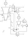
- FIG. 1 shows schematically and by way of example a plant 1 comprising a removal condensing turbine 2, to which a generator 10 is coupled.
- the extraction condensing turbine 2 has a steam inlet 11 and a steam outlet 12.
- the steam outlet 12 opens into a condenser 13.
- the removal condenser turbine 2 has a steam removal 3, from which a steam line 4 branches off, and a first valve 14 for pressure maintenance at the high-pressure turbine 15.
- FIG. 1 shows various Schudampfentsure 17 and a branch to a device 7 for preheating and evaporation of a working medium of an Organic Rankine cycle 8 and another branch to a heating condenser 5 of a district heating network. 6
- the Organic Rankine Cycle 8 comprises, in addition to the device 7 for preheating and vaporizing a suitable working medium, a second valve 18, an ORC turbine 19, a generator 20 coupled to the ORC turbine 19, an ORC condenser 21 and an ORC pump 22 ,
- a third valve 23 is arranged in the steam line 4 immediately before the heating capacitor 5.
- the heating condenser 5 and the device 7 are arranged parallel to one another in the steam line 4.
- a pressure control 9 is provided, with which amounts of steam can be adjusted, which are supplied during operation to the heating capacitor 5 and the device 7 for preheating and evaporation of a working medium of the Organic Rankine cycle 8.
- the pressure control 9 receives information from a measuring point 24 about the pressure prevailing in the steam line 4.
- a nominal / actual adjustment for the Organic Rankine Cycle 8 is performed via a power controller 25.
- About the second valve 18 is an indirect control of Steam removal for the ORC circuit 8. Accordingly, there is a direct control of the heating capacitor 6 via the third valve 23rd
Landscapes
- Engineering & Computer Science (AREA)
- Chemical & Material Sciences (AREA)
- Combustion & Propulsion (AREA)
- Mechanical Engineering (AREA)
- General Engineering & Computer Science (AREA)
- Engine Equipment That Uses Special Cycles (AREA)
- Control Of Turbines (AREA)
Abstract
Description
- Die Erfindung betrifft eine Anlage umfassend eine Entnahmekondensationsturbine sowie ein Verfahren zu deren Betrieb.
- Blockheizkraftwerke (BHKW) stellen bei regionalen Stromerzeugern und Stadtwerken ein weit verbreitetes Anlagenkonzept dar, welches die Stromerzeugung mit Fernwärme- und/oder industriellen Wärmebereitstellung in vorteilhafter Weise koppelt und hohe thermische Wirkungsgrade und niedrige CO2-Emissionen ermöglichen lässt. Durch die aktuellen Veränderungen des Strommarktes und eine veränderte Einspeisevergütung wird dieses Konzept zunehmend unwirtschaftlich und mit neuen Herausforderungen konfrontiert. Erzielbare Stromerlöse und Jahreszeit-spezifische Wärmebereitstellung verhalten sich zunehmend gegenläufig und die Kopplung von Wärme- und Stromerzeugung erschweren einen flexiblen Betrieb. BHKW-Anlagen können damit nur sehr eingeschränkt auf die fluktuierende regenerative Stromeinspeisung und die damit verbundenen Strompreisänderungen reagieren. Um weiterhin eine wirtschaftliche Fahrweise sicherzustellen, sind daher standortspezifische Anpassungen des Anlagenkonzeptes und eine höhere Flexibilität zwischen Wärme- und Stromerzeugung erforderlich. Ein weiterer Faktor für den wirtschaftlichen Betrieb sind günstige Einkaufspreise für nicht speicherbare Brennstoffe wie z.B. Erdgas oder Müll, die nur über langfristige Abnahme- bzw. Lieferverträge erreicht werden können und die gewünschte Flexibilität auf der Produktseite weiter erschweren.
- Heutige BHKW-Konzepte existieren in unterschiedlicher Ausgestaltung und die Energieerzeugung erfolgt entweder durch Verbrennung fossiler oder biogener Brennstoffe wie Biomasse und Müll. Die bei der Verbrennung freigesetzte Wärme wird in der weiteren Prozesskette entweder direkt über einen Dampfkessel oder indirekt über das Abgas eines Gasmotors bzw. einer Gasturbine in einen Wasser/Dampfkreislauf eingekoppelt und in vielen Fällen über eine Entnahmekondensationsturbine zur Stromerzeugung genutzt. Der erzeugte und exergetisch hochwertige Dampf wird innerhalb der Turbine auf einen Druck kleiner 10 bar entspannt und dann über die Niederdruckbeschaufelung in einen Kondensator geleitet oder einer Dampfentnahme zugeführt, die im weiteren Verlauf die Wärme an ein Wärmenetz überträgt. Die Dampfentnahme an der Entnahmekondensationsturbine kann dabei geregelt oder ungeregelt erfolgen.
- Der Erfindung liegt das Problem zugrunde, dass Entnahmekondensationsturbinen bei hoher geregelter Dampfentnahme den Niederdruck-Teil mit der Niederdruckbeschaufelung weitestgehend verschließen und die Gefahr der Ventilationswärme und einer Temperaturüberschreitung an der letzten Turbinenstufe besteht. Um einen Ausfall der Dampfturbine zu vermeiden, muss die Dampfentnahme daher auf einen maximalen Wert begrenzt werden. Im Gegensatz zu einer hohen Dampfentnahme steigt bei sehr geringer Entnahme die Durchströmung des Niederdruck-Teils und die Belastung des Kondensators an, was einen Anstieg der Kondensations- und Turbinenaustrittstemperatur in Abhängigkeit der Umgebungstemperatur zur Folge hat. Auch in diesem Fall kann eine Leistungsbegrenzung erforderlich werden. Die unterschiedliche Belastung des Niederdruck-Teiles kann weiterhin zur Folge haben, dass die Anfälligkeit der Rotordynamik in bestimmten Betriebssituationen steigt. Speziell bei Sommerbetrieb mit geringem Wärmebedarf und hohen Umgebungstemperaturen entsteht eine starke Belastung des kalten Endes der Dampfturbine, während in der kälteren Jahreszeit die Niederdruck-Turbine und der Kondensator größtenteils in Teillast betrieben werden müssen. Eine zu große Differenz zwischen beiden Auslegungsfällen für die Dampfturbine erhöht die Risiken während des Betriebes. Eine zusätzliche oder alternative ungeregelte Entnahme kann dieses Risiko noch verstärken, da Änderungen des Düsendruckes an der Hochdruck-Beschaufelung ebenfalls zu Problemen der Rotordynamik führen können. Stark veränderliche geregelte als auch ungeregelte Entnahmen verändern auch den Axialschub an der Turbine, was durch entsprechenden Mehraufwand an Lagern und Kompensatoren ausgeglichen werden muss. Da Entnahmekondensationsturbinen durch ihre unterschiedlichen Entnahmemengen und Leistungsgrößen keine Standardmaschinen darstellen, müssen sie auf die jeweiligen Betriebsfälle optimiert werden und es entstehen höhere Kosten, Fertigungszeiten und Betriebsrisiken.
- Bei bisherigen BHKW-Konzepten mit Entnahmekondensationsmaschinen wurden häufig längere Inbetriebsetzungszeiten und anlagentechnische Anpassungen erforderlich. Eine Anpassung auf die veränderten Rahmenbedingungen des Strommarktes ist nur eingeschränkt möglich und erfordert risikoreiche Anpassungen an Dampfturbine und verbindenden Wasser/Dampfsystemen. In vielen Fällen muss daher auf einen höheren Stromerlös zugunsten eines sicheren Anlagenbetriebes verzichtet werden. Da die Kesselleistung aufgrund von Bezugsverpflichtungen auf der Brennstoffseite nicht immer reduziert werden kann, muss in einigen Fällen die erzeugte Wärme in den Sommermonaten verworfen werden. Veränderungen in den Wärmenetzen können diesen Trend zusätzlich verschärfen.
- Aufgabe der Erfindung ist es, eine Vorrichtung und ein Verfahren anzugeben, bei denen die Flexibilität eines BHKW-Konzeptes mit Entnahmekondensationsmaschine verbessert und der Dampfturbinenbetrieb vergleichmäßigt wird.
- Erfindungsgemäß wird die auf eine Vorrichtung gerichtete Aufgabe gelöst durch eine Anlage umfassend eine Entnahmekondensationsturbine mit einer Dampfentnahme und einer von der Dampfentnahme abzweigenden Dampfleitung, in der ein Heizkondensator eines Fernwärmenetzes angeordnet ist, bei der in der Dampfleitung ferner eine Vorrichtung zum Vorwärmen und Verdampfen eines Arbeitsmediums eines Organic Rankine Cycles (ORC) parallel zum Heizkondensator des Fernwärmenetzes angeordnet ist. In Organic Rankine Cycles erfolgt der Betrieb von Dampfturbinen mit einem anderen Arbeitsmedium als Wasserdampf.
- Der parallel zum Heizkondensator angeordnete ORC-Prozess entnimmt ebenfalls Wärme aus der Dampfentnahme der Entnahmekondensationsmaschine und kann somit den veränderlichen Wärmebedarf des Fernwärmenetzes ausgleichen, wodurch eine weitestgehend gleichbleibende Dampfentnahme an der Turbine möglich wird. Somit wird eine vergleichmäßigte Fahrweise der Entnahmekondensationsturbine bei gleichzeitig veränderlicher Dampfversorgung eines Heizdampfnetzes und flexiblerer Stromerzeugung sicherstellt.
- In einer vorteilhaften Ausführungsform der Erfindung ist eine Druckregelung vorgesehen, mit welcher die Dampfmengen eingestellt werden können, die im Betrieb dem Heizkondensator bzw. der Vorrichtung zum Vorwärmen und Verdampfen eines Arbeitsmediums des Organic Rankine Cycle zugeführt werden. Somit kann automatisch, schnell und flexibel auf den Heizwärmebedarf im Fernwärmenetz reagiert werden.
- In einer weiteren vorteilhaften Ausführungsform der Erfindung ist die Druckregelung so ausgelegt, dass ein Entnahmedruck an der Dampfentnahme unabhängig von einem Wärmebedarf im Fernwärmenetz innerhalb eines vorab definierten Bereichs gehalten wird.
- Es ist zweckmäßig wenn das Arbeitsmedium für den Organic Rankine Cycle R1332zd, R1336 oder R1224 ist. Um die Integration der ORC-Anlage optimal an die Dampfentnahme der Entnahmekondensationsturbine und der Versorgung des Fernwärmenetzes anzupassen, ist es nämlich notwendig, ein Arbeitsmedium zu wählen, dessen Verdampfungstemperatur eine ausreichende Grädigkeit (pinch point) zwischen Dampfentnahme und ORC-Arbeitsmedium sicherstellt und dessen Isobaren im Heizdampfbereich einen möglichst großen Abstand aufweisen. Üblicherweise erfolgt die Aufwärmung des Fernwärmenetzes auf eine Temperatur von ca. 130°C und erfordert eine Dampfentnahme an der Turbine von >140°C. Da der ORC-Kreislauf parallel zum Heizkondensator angeordnet ist, muss das Arbeitsmedium so gewählt werden, dass einerseits eine Verdampfungstemperatur < 130°C und andererseits ein möglichst isentroper Verlauf der Phasengrenze des Arbeitsmediums und ein Kondensationsdruck größer 1 bar erreicht werden kann. Des Weiteren ist für eine besonders kostengünstige Ausgestaltung des ORC-Prozesses neben einem minimalen ODP [Ozonschichtschädigendes Potenzial (ODP), Ozone Depletion Potential] und GWP [Treibhausfaktor (GWP, Global Warming Potential)] ein nichtbrennbares Arbeitsmedium erforderlich, um die kostenintensiven Anforderungen des Ex-Schutzes vermeiden zu können. Um unter den genannten Anforderungen einen maximalen Wirkungsgrad zu erreichen, werden für den der Dampfturbine nachgeschalteten ORC-Prozess die genannte Arbeitsmedien vorgeschlagen.
- Die auf ein Verfahren gerichtete Aufgabe wird gelöst durch ein Verfahren zum Betreiben einer Anlage umfassend eine Entnahmekondensationsturbine mit einer Dampfentnahme, bei dem Dampf für einen Heizkondensator eines Fernwärmenetzes an der Dampfentnahme entnommen wird, bei dem ferner Dampf für einen Organic Rankine Cycle geregelt so an der Dampfentnahme entnommen wird, dass ein Entnahmedruck an der Dampfentnahme innerhalb eines vorab definierten Bereichs gehalten wird.
- Es ist vorteilhaft, wenn der Organic Rankine Cycle für eine Sekundärleistungsregelung eingesetzt wird, indem eine dem Heizkondensator zur Verfügung gestellte Dampfmenge zumindest zeitweise unter Ausnutzung eines Wärmespeicherreservoirs des Fernwärmenetzes und einer erlaubten Bandbreite einer Vorlauftemperatur im Fernwärmenetz verringert wird. Durch Wärmeverschiebung zwischen Heizkondensator und ORC-Verdampfer kann mehr Wärme der ORC-Turbine zur Verfügung gestellt werden. Aufgrund der Flexibilität der Dampfentnahme an der Turbine ist dies möglich, insbesondere, da ORC-Prozesse keine überwachungspflichtigen Anlagen darstellen und über eine leittechnische Schnittstelle direkt vom Netzbetreiber als virtuelles Kraftwerk gesteuert werden können.
- Es ist weiterhin vorteilhaft, wenn als Arbeitsmedium für den ORC R1332zd oder R1336 oder R1224 verwendet wird.
- Ganz allgemein ist mit der vorgeschlagenen Lösung eine Wirkungsgraderhöhung erreichbar, wenn ein ORC-Prozess dem Wasser/Dampf Kreislauf mit Entnahmekondensationsturbine thermodynamisch nachgeschaltet wird, da der Dampfprozess für hohe Temperaturen des Arbeitsmediums und der ORC-Prozess für niedrige Temperaturen den maximal möglichen Wirkungsgrad verspricht.
- Neben der Flexibilisierung der Wärmenutzung hat der ORC-Prozess auch die Aufgabe, die Regelung des Entnahmedruckes innerhalb der Dampfturbine zu unterstützen. Die Regelung des ORC-Prozesses erfolgt in gestufter Form durch eine primäre Leistungs- und sekundäre Begrenzungsregelung. Somit ist sichergestellt, dass die durch den Netzverteiler angeforderte Sekundärleistung den Betrieb der Entnahmekondensationsmaschine nicht negativ beeinflusst.
- Die Anlage gemäß der Erfindung ist kompakt und kostengünstig und ermöglicht eine Verkleinerung des Niederdruckteiles der Dampfturbine und des Kondensators. Aufgrund der thermodynamischen Stoffeigenschaften organischer Arbeitsmedien ist ein höherer Wirkungsgrad im niedrigen Temperaturbereich und bei höheren Umgebungstemperaturen verglichen zu einer Dampfturbine erreichbar. Ein weiterer Vorteil ist die einfache Nachrüstbarkeit in ein vorhandenes Niederdruckdampfnetz (3-6bar) und nachträgliche Flexibilisierung eines vorhandenen BHKW-Anlagenkonzeptes.
- Die Erfindung wird beispielhaft anhand der Zeichnung näher erläutert. Es zeigt schematisch und nicht maßstäblich:
- Figur 1
- eine Anlage mit Entnahmekondensationsturbine und ORC-Kreislauf nach der Erfindung.
- Die
Figur 1 zeigt schematisch und beispielhaft eine Anlage 1 umfassend eine Entnahmekondensationsturbine 2, an die ein Generator 10 gekoppelt ist. Die Entnahmekondensationsturbine 2 weist einen Dampfeinlass 11 und einen Dampfauslass 12 auf. Der Dampfauslass 12 mündet in einen Kondensator 13. Ferner weist die Entnahmekondensationsturbine 2 eine Dampfentnahme 3 auf, von der eine Dampfleitung 4 abzweigt, sowie ein erstes Ventil 14 zur Druckhaltung an der Hochdruckturbine 15. - Die Dampfleitung 4 verzweigt sich über eine sogenannte Dampfschiene 16, über die mehrere Verbraucher an die Dampfleitung 4 geschaltet werden können.
Figur 1 zeigt verschiedene Heizdampfentnahmen 17 sowie eine Abzweigung zu einer Vorrichtung 7 zum Vorwärmen und Verdampfen eines Arbeitsmediums eines Organic Rankine Cycles 8 und eine weitere Abzweigung zu einem Heizkondensator 5 eines Fernwärmenetzes 6. - Der Organic Rankine Cycle 8 umfasst neben der Vorrichtung 7 zum Vorwärmen und Verdampfen eines geeigneten Arbeitsmediums ein zweites Ventil 18, eine ORC-Turbine 19, einen an die ORC-Turbine 19 gekoppelten Generator 20, einen ORC-Kondensator 21 und eine ORC-Pumpe 22.
- Ein drittes Ventil 23 ist in der Dampfleitung 4 unmittelbar vor dem Heizkondensator 5 angeordnet. In
Figur 1 ist erkennbar, dass Heizkondensator 5 und Vorrichtung 7 parallel zueinander in der Dampfleitung 4 angeordnet sind. - In der Ausführungsform der
Figur 1 ist eine Druckregelung 9 vorgesehen, mit welcher Dampfmengen eingestellt werden können, die im Betrieb dem Heizkondensator 5 bzw. der Vorrichtung 7 zum Vorwärmen und Verdampfen eines Arbeitsmediums des Organic Rankine Cycles 8 zugeführt werden. Zu diesem Zweck erhält die Druckregelung 9 von einer Messstelle 24 Informationen über den in der Dampfleitung 4 vorherrschenden Druck. Außerdem wird über einen Leistungsregler 25 ein Soll/Ist-Abgleich für den Organic Rankine Cycle 8 durchgeführt. Über das zweite Ventil 18 erfolgt eine indirekte Regelung der Dampfentnahme für den ORC-Kreislauf 8. Entsprechend erfolgt eine direkte Regelung für den Heizkondensator 6 über das dritte Ventil 23.
Claims (9)
- Anlage (1) umfassend eine Entnahmekondensationsturbine (2) mit einer Dampfentnahme (3) und einer von der Dampfentnahme (3) abzweigenden Dampfleitung (4), in der ein Heizkondensator (5) eines Fernwärmenetzes (6) angeordnet ist, dadurch gekennzeichnet, dass in der Dampfleitung (4) ferner eine Vorrichtung (7) zum Vorwärmen und Verdampfen eines Arbeitsmediums eines Organic Rankine Cycles (8) parallel zum Heizkondensator (5) des Fernwärmenetzes (6) angeordnet ist.
- Anlage (1) nach Anspruch 1, wobei eine Druckregelung (9) vorgesehen ist, mit welcher Dampfmengen eingestellt werden können, die im Betrieb dem Heizkondensator (5) bzw. der Vorrichtung (7) zum Vorwärmen und Verdampfen eines Arbeitsmediums des Organic Rankine Cycles (8) zugeführt werden.
- Anlage (1) nach Anspruch 2, wobei die Druckregelung (9) so ausgelegt ist, dass ein Entnahmedruck an der Dampfentnahme (3) unabhängig von einem Wärmebedarf im Fernwärmenetz (6) innerhalb eines vorab definierten Bereichs gehalten wird.
- Anlage (1) nach einem der Ansprüche 1 bis 3, wobei das Arbeitsmedium für den Organic Rankine Cycle (8) nichtbrennbar ist.
- Anlage (1) nach einem der Ansprüche 1 bis 4, wobei das Arbeitsmedium für den Organic Rankine Cycle (8) eine Verdampfungstemperatur unterhalb der Temperatur aufweist, auf die das Fernwärmenetz (6) im Betrieb aufgewärmt wird.
- Anlage (1) nach einem der Ansprüche 1 bis 5, wobei das Arbeitsmedium für den Organic Rankine Cycle (8) R1332zd, R1336 oder R1224 ist.
- Verfahren zum Betreiben einer Anlage (1) umfassend eine Entnahmekondensationsturbine (2) mit einer Dampfentnahme (3), bei dem Dampf für einen Heizkondensator (5) eines Fernwärmenetzes (6) an der Dampfentnahme (3) entnommen wird, dadurch gekennzeichnet, dass ferner Dampf für einen Organic Rankine Cycle (8) geregelt so an der Dampfentnahme (3) entnommen wird, dass ein Entnahmedruck an der Dampfentnahme (3) innerhalb eines vorab definierten Bereichs gehalten wird.
- Verfahren nach Anspruch 7, wobei der Organic Rankine Cycle (8) für eine Sekundärleistungsregelung eingesetzt wird, indem eine dem Heizkondensator (5) zur Verfügung gestellte Dampfmenge zumindest zeitweise unter Ausnutzung eines Wärmespeicherreservoirs des Fernwärmenetzes (6) und einer erlaubten Bandbreite einer Vorlauftemperatur im Fernwärmenetz (6) verringert wird.
- Verfahren nach einem der Ansprüche 7 oder 8, wobei als Arbeitsmedium für den Organic Rankine Cycle (8) R1332zd oder R1336 oder R1224 verwendet wird.
Priority Applications (3)
| Application Number | Priority Date | Filing Date | Title |
|---|---|---|---|
| EP18159456.5A EP3533976B1 (de) | 2018-03-01 | 2018-03-01 | Anlage mit entnahmekondensationsturbine und orc-prozess |
| DK18159456.5T DK3533976T3 (da) | 2018-03-01 | 2018-03-01 | Anlæg med ekstraktionskondensationsturbine og ORC-proces |
| PCT/EP2019/051732 WO2019166160A1 (de) | 2018-03-01 | 2019-01-24 | Anlage mit entnahmekondensationsturbine und orc-prozess |
Applications Claiming Priority (1)
| Application Number | Priority Date | Filing Date | Title |
|---|---|---|---|
| EP18159456.5A EP3533976B1 (de) | 2018-03-01 | 2018-03-01 | Anlage mit entnahmekondensationsturbine und orc-prozess |
Publications (2)
| Publication Number | Publication Date |
|---|---|
| EP3533976A1 true EP3533976A1 (de) | 2019-09-04 |
| EP3533976B1 EP3533976B1 (de) | 2020-08-12 |
Family
ID=61526746
Family Applications (1)
| Application Number | Title | Priority Date | Filing Date |
|---|---|---|---|
| EP18159456.5A Active EP3533976B1 (de) | 2018-03-01 | 2018-03-01 | Anlage mit entnahmekondensationsturbine und orc-prozess |
Country Status (3)
| Country | Link |
|---|---|
| EP (1) | EP3533976B1 (de) |
| DK (1) | DK3533976T3 (de) |
| WO (1) | WO2019166160A1 (de) |
Cited By (1)
| Publication number | Priority date | Publication date | Assignee | Title |
|---|---|---|---|---|
| WO2025045452A1 (de) * | 2023-09-01 | 2025-03-06 | Siemens Energy Global GmbH & Co. KG | Kondensationsdampfturbinenanlage sowie verfahren zum betreiben einer solchen dampfturbinenanlage |
Families Citing this family (3)
| Publication number | Priority date | Publication date | Assignee | Title |
|---|---|---|---|---|
| CN112963210A (zh) * | 2021-03-17 | 2021-06-15 | 国网天津市电力公司电力科学研究院 | 一种具有热电平衡能力的综合控制装置 |
| CN116181436B (zh) * | 2022-12-02 | 2026-04-21 | 国网山东省电力公司电力科学研究院 | 一种基于二次回路调整的热电联产核电机组调峰方法和装置 |
| CN120042672B (zh) * | 2025-02-28 | 2025-10-24 | 中国电力工程顾问集团有限公司 | 一种实现核电机组灵活调峰的热电联产系统及方法 |
Citations (3)
| Publication number | Priority date | Publication date | Assignee | Title |
|---|---|---|---|---|
| US20110203279A1 (en) * | 2008-09-10 | 2011-08-25 | Suez Environnement | Cogeneration device |
| US20130247571A1 (en) * | 2010-12-08 | 2013-09-26 | Andreas Pickard | Retrofitting a heating steam extraction facility in a fossil-fired power plant |
| US20140000668A1 (en) * | 2012-06-27 | 2014-01-02 | Daniel Lessard | Electric Power Generation |
-
2018
- 2018-03-01 EP EP18159456.5A patent/EP3533976B1/de active Active
- 2018-03-01 DK DK18159456.5T patent/DK3533976T3/da active
-
2019
- 2019-01-24 WO PCT/EP2019/051732 patent/WO2019166160A1/de not_active Ceased
Patent Citations (3)
| Publication number | Priority date | Publication date | Assignee | Title |
|---|---|---|---|---|
| US20110203279A1 (en) * | 2008-09-10 | 2011-08-25 | Suez Environnement | Cogeneration device |
| US20130247571A1 (en) * | 2010-12-08 | 2013-09-26 | Andreas Pickard | Retrofitting a heating steam extraction facility in a fossil-fired power plant |
| US20140000668A1 (en) * | 2012-06-27 | 2014-01-02 | Daniel Lessard | Electric Power Generation |
Cited By (1)
| Publication number | Priority date | Publication date | Assignee | Title |
|---|---|---|---|---|
| WO2025045452A1 (de) * | 2023-09-01 | 2025-03-06 | Siemens Energy Global GmbH & Co. KG | Kondensationsdampfturbinenanlage sowie verfahren zum betreiben einer solchen dampfturbinenanlage |
Also Published As
| Publication number | Publication date |
|---|---|
| WO2019166160A1 (de) | 2019-09-06 |
| DK3533976T3 (da) | 2020-10-19 |
| EP3533976B1 (de) | 2020-08-12 |
Similar Documents
| Publication | Publication Date | Title |
|---|---|---|
| EP0439754B1 (de) | Verfahren zum Anfahren einer Kombianlage | |
| EP0819209B1 (de) | Verfahren zum betreiben eines abhitzedampferzeugers sowie danach arbeitender abhitzedampferzeuger | |
| EP3533976B1 (de) | Anlage mit entnahmekondensationsturbine und orc-prozess | |
| DE112016003348B4 (de) | Wasserversorgungssystem, wasserversorgungsverfahren, und dampf erzeugende anlage, die mit wasserversorgungssystem bereitgestellt wird | |
| EP1059488B1 (de) | Verfahren und Anlage zum Erwärmen eines flüssigen Mediums | |
| DE2555897A1 (de) | Verfahren zum ausnutzen der ueberschusswaerme eines elektrizitaetswerks | |
| EP0778397A2 (de) | Verfahren zum Betrieb einer mit einem Abhitzedampferzeuger und einem Dampfverbraucher kombinierten Dampfturbogruppe | |
| EP0523467A1 (de) | Verfahren zum Betreiben einer Gas- und Dampfturbinenanlage und Anlage zur Durchführung des Verfahrens | |
| DE102010036487A1 (de) | System und Verfahren zum Liefern von Brennstoff an eine Gasturbine | |
| DE102018123663A1 (de) | Brennstoffvorwärmsystem für eine Verbrennungsgasturbine | |
| DE102008055545A1 (de) | Verfahren und Vorrichtung zum Hochfahren eines Kombinationszyklus-Stromerzeugungssystems | |
| CH633610A5 (de) | Kombiniertes gas/dampfturbinenkraftwerk mit gegendruckturbine, insbesondere fuer industriezwecke. | |
| EP2326800B1 (de) | Dampfkraftanlage zur erzeugung elektrischer energie | |
| EP2224104B1 (de) | Verfahren zum Betreiben eines Kraftwerks | |
| EP2592241A1 (de) | Verfahren zum Betrieb einer Gas- und Dampfturbinenanlage für die Frequenzstützung | |
| EP2288791B1 (de) | Betrieb einer gas- und dampfturbinenanlage mittels frequenzumrichter | |
| EP2802757B1 (de) | Gaskraftwerk | |
| DE4447044C1 (de) | Verfahren zur Verminderung der Anfahrverluste eines Kraftwerksblockes | |
| DE10155508C5 (de) | Verfahren und Vorrichtung zur Erzeugung von elektrischer Energie | |
| AT518186B1 (de) | Wärmekraftwerk und Verfahren zum Speichern von Wärme | |
| CH698282B1 (de) | Kombikraftwerkssystem. | |
| EP3511534A1 (de) | Dampfkraftwerk und verfahren zum betreiben eines dampfkraftwerks | |
| EP2480763B1 (de) | Dampfkraftwerk | |
| DE2512774C2 (de) | Kombinierte Gas-Dampfturbinenanlage | |
| EP2964910B1 (de) | Verfahren zum flexiblen betrieb einer kraftwerksanlage |
Legal Events
| Date | Code | Title | Description |
|---|---|---|---|
| PUAI | Public reference made under article 153(3) epc to a published international application that has entered the european phase |
Free format text: ORIGINAL CODE: 0009012 |
|
| STAA | Information on the status of an ep patent application or granted ep patent |
Free format text: STATUS: THE APPLICATION HAS BEEN PUBLISHED |
|
| AK | Designated contracting states |
Kind code of ref document: A1 Designated state(s): AL AT BE BG CH CY CZ DE DK EE ES FI FR GB GR HR HU IE IS IT LI LT LU LV MC MK MT NL NO PL PT RO RS SE SI SK SM TR |
|
| AX | Request for extension of the european patent |
Extension state: BA ME |
|
| STAA | Information on the status of an ep patent application or granted ep patent |
Free format text: STATUS: REQUEST FOR EXAMINATION WAS MADE |
|
| 17P | Request for examination filed |
Effective date: 20200302 |
|
| RBV | Designated contracting states (corrected) |
Designated state(s): AL AT BE BG CH CY CZ DE DK EE ES FI FR GB GR HR HU IE IS IT LI LT LU LV MC MK MT NL NO PL PT RO RS SE SI SK SM TR |
|
| GRAP | Despatch of communication of intention to grant a patent |
Free format text: ORIGINAL CODE: EPIDOSNIGR1 |
|
| STAA | Information on the status of an ep patent application or granted ep patent |
Free format text: STATUS: GRANT OF PATENT IS INTENDED |
|
| INTG | Intention to grant announced |
Effective date: 20200416 |
|
| GRAS | Grant fee paid |
Free format text: ORIGINAL CODE: EPIDOSNIGR3 |
|
| GRAA | (expected) grant |
Free format text: ORIGINAL CODE: 0009210 |
|
| STAA | Information on the status of an ep patent application or granted ep patent |
Free format text: STATUS: THE PATENT HAS BEEN GRANTED |
|
| AK | Designated contracting states |
Kind code of ref document: B1 Designated state(s): AL AT BE BG CH CY CZ DE DK EE ES FI FR GB GR HR HU IE IS IT LI LT LU LV MC MK MT NL NO PL PT RO RS SE SI SK SM TR |
|
| REG | Reference to a national code |
Ref country code: CH Ref legal event code: EP |
|
| REG | Reference to a national code |
Ref country code: DE Ref legal event code: R096 Ref document number: 502018002140 Country of ref document: DE |
|
| REG | Reference to a national code |
Ref country code: IE Ref legal event code: FG4D Free format text: LANGUAGE OF EP DOCUMENT: GERMAN |
|
| REG | Reference to a national code |
Ref country code: AT Ref legal event code: REF Ref document number: 1301758 Country of ref document: AT Kind code of ref document: T Effective date: 20200915 |
|
| REG | Reference to a national code |
Ref country code: DK Ref legal event code: T3 Effective date: 20201014 |
|
| REG | Reference to a national code |
Ref country code: SE Ref legal event code: TRGR |
|
| REG | Reference to a national code |
Ref country code: DE Ref legal event code: R081 Ref document number: 502018002140 Country of ref document: DE Owner name: SIEMENS ENERGY GLOBAL GMBH & CO. KG, DE Free format text: FORMER OWNER: SIEMENS AKTIENGESELLSCHAFT, 80333 MUENCHEN, DE |
|
| REG | Reference to a national code |
Ref country code: LT Ref legal event code: MG4D |
|
| REG | Reference to a national code |
Ref country code: NL Ref legal event code: MP Effective date: 20200812 |
|
| RAP2 | Party data changed (patent owner data changed or rights of a patent transferred) |
Owner name: SIEMENS ENERGY GLOBAL GMBH & CO. KG |
|
| PG25 | Lapsed in a contracting state [announced via postgrant information from national office to epo] |
Ref country code: BG Free format text: LAPSE BECAUSE OF FAILURE TO SUBMIT A TRANSLATION OF THE DESCRIPTION OR TO PAY THE FEE WITHIN THE PRESCRIBED TIME-LIMIT Effective date: 20201112 Ref country code: HR Free format text: LAPSE BECAUSE OF FAILURE TO SUBMIT A TRANSLATION OF THE DESCRIPTION OR TO PAY THE FEE WITHIN THE PRESCRIBED TIME-LIMIT Effective date: 20200812 Ref country code: LT Free format text: LAPSE BECAUSE OF FAILURE TO SUBMIT A TRANSLATION OF THE DESCRIPTION OR TO PAY THE FEE WITHIN THE PRESCRIBED TIME-LIMIT Effective date: 20200812 Ref country code: FI Free format text: LAPSE BECAUSE OF FAILURE TO SUBMIT A TRANSLATION OF THE DESCRIPTION OR TO PAY THE FEE WITHIN THE PRESCRIBED TIME-LIMIT Effective date: 20200812 Ref country code: GR Free format text: LAPSE BECAUSE OF FAILURE TO SUBMIT A TRANSLATION OF THE DESCRIPTION OR TO PAY THE FEE WITHIN THE PRESCRIBED TIME-LIMIT Effective date: 20201113 Ref country code: NO Free format text: LAPSE BECAUSE OF FAILURE TO SUBMIT A TRANSLATION OF THE DESCRIPTION OR TO PAY THE FEE WITHIN THE PRESCRIBED TIME-LIMIT Effective date: 20201112 |
|
| PG25 | Lapsed in a contracting state [announced via postgrant information from national office to epo] |
Ref country code: PL Free format text: LAPSE BECAUSE OF FAILURE TO SUBMIT A TRANSLATION OF THE DESCRIPTION OR TO PAY THE FEE WITHIN THE PRESCRIBED TIME-LIMIT Effective date: 20200812 Ref country code: NL Free format text: LAPSE BECAUSE OF FAILURE TO SUBMIT A TRANSLATION OF THE DESCRIPTION OR TO PAY THE FEE WITHIN THE PRESCRIBED TIME-LIMIT Effective date: 20200812 Ref country code: RS Free format text: LAPSE BECAUSE OF FAILURE TO SUBMIT A TRANSLATION OF THE DESCRIPTION OR TO PAY THE FEE WITHIN THE PRESCRIBED TIME-LIMIT Effective date: 20200812 Ref country code: LV Free format text: LAPSE BECAUSE OF FAILURE TO SUBMIT A TRANSLATION OF THE DESCRIPTION OR TO PAY THE FEE WITHIN THE PRESCRIBED TIME-LIMIT Effective date: 20200812 Ref country code: IS Free format text: LAPSE BECAUSE OF FAILURE TO SUBMIT A TRANSLATION OF THE DESCRIPTION OR TO PAY THE FEE WITHIN THE PRESCRIBED TIME-LIMIT Effective date: 20201212 |
|
| PG25 | Lapsed in a contracting state [announced via postgrant information from national office to epo] |
Ref country code: EE Free format text: LAPSE BECAUSE OF FAILURE TO SUBMIT A TRANSLATION OF THE DESCRIPTION OR TO PAY THE FEE WITHIN THE PRESCRIBED TIME-LIMIT Effective date: 20200812 Ref country code: RO Free format text: LAPSE BECAUSE OF FAILURE TO SUBMIT A TRANSLATION OF THE DESCRIPTION OR TO PAY THE FEE WITHIN THE PRESCRIBED TIME-LIMIT Effective date: 20200812 Ref country code: CZ Free format text: LAPSE BECAUSE OF FAILURE TO SUBMIT A TRANSLATION OF THE DESCRIPTION OR TO PAY THE FEE WITHIN THE PRESCRIBED TIME-LIMIT Effective date: 20200812 Ref country code: SM Free format text: LAPSE BECAUSE OF FAILURE TO SUBMIT A TRANSLATION OF THE DESCRIPTION OR TO PAY THE FEE WITHIN THE PRESCRIBED TIME-LIMIT Effective date: 20200812 |
|
| REG | Reference to a national code |
Ref country code: DE Ref legal event code: R097 Ref document number: 502018002140 Country of ref document: DE |
|
| PG25 | Lapsed in a contracting state [announced via postgrant information from national office to epo] |
Ref country code: AL Free format text: LAPSE BECAUSE OF FAILURE TO SUBMIT A TRANSLATION OF THE DESCRIPTION OR TO PAY THE FEE WITHIN THE PRESCRIBED TIME-LIMIT Effective date: 20200812 Ref country code: ES Free format text: LAPSE BECAUSE OF FAILURE TO SUBMIT A TRANSLATION OF THE DESCRIPTION OR TO PAY THE FEE WITHIN THE PRESCRIBED TIME-LIMIT Effective date: 20200812 |
|
| PLBE | No opposition filed within time limit |
Free format text: ORIGINAL CODE: 0009261 |
|
| STAA | Information on the status of an ep patent application or granted ep patent |
Free format text: STATUS: NO OPPOSITION FILED WITHIN TIME LIMIT |
|
| PG25 | Lapsed in a contracting state [announced via postgrant information from national office to epo] |
Ref country code: SK Free format text: LAPSE BECAUSE OF FAILURE TO SUBMIT A TRANSLATION OF THE DESCRIPTION OR TO PAY THE FEE WITHIN THE PRESCRIBED TIME-LIMIT Effective date: 20200812 |
|
| 26N | No opposition filed |
Effective date: 20210514 |
|
| PG25 | Lapsed in a contracting state [announced via postgrant information from national office to epo] |
Ref country code: SI Free format text: LAPSE BECAUSE OF FAILURE TO SUBMIT A TRANSLATION OF THE DESCRIPTION OR TO PAY THE FEE WITHIN THE PRESCRIBED TIME-LIMIT Effective date: 20200812 |
|
| PG25 | Lapsed in a contracting state [announced via postgrant information from national office to epo] |
Ref country code: MC Free format text: LAPSE BECAUSE OF FAILURE TO SUBMIT A TRANSLATION OF THE DESCRIPTION OR TO PAY THE FEE WITHIN THE PRESCRIBED TIME-LIMIT Effective date: 20200812 |
|
| REG | Reference to a national code |
Ref country code: CH Ref legal event code: PL |
|
| REG | Reference to a national code |
Ref country code: BE Ref legal event code: MM Effective date: 20210331 |
|
| PG25 | Lapsed in a contracting state [announced via postgrant information from national office to epo] |
Ref country code: FR Free format text: LAPSE BECAUSE OF NON-PAYMENT OF DUE FEES Effective date: 20210331 Ref country code: IE Free format text: LAPSE BECAUSE OF NON-PAYMENT OF DUE FEES Effective date: 20210301 Ref country code: CH Free format text: LAPSE BECAUSE OF NON-PAYMENT OF DUE FEES Effective date: 20210331 Ref country code: LU Free format text: LAPSE BECAUSE OF NON-PAYMENT OF DUE FEES Effective date: 20210301 Ref country code: LI Free format text: LAPSE BECAUSE OF NON-PAYMENT OF DUE FEES Effective date: 20210331 |
|
| PGFP | Annual fee paid to national office [announced via postgrant information from national office to epo] |
Ref country code: SE Payment date: 20220307 Year of fee payment: 5 |
|
| PG25 | Lapsed in a contracting state [announced via postgrant information from national office to epo] |
Ref country code: BE Free format text: LAPSE BECAUSE OF NON-PAYMENT OF DUE FEES Effective date: 20210331 |
|
| GBPC | Gb: european patent ceased through non-payment of renewal fee |
Effective date: 20220301 |
|
| REG | Reference to a national code |
Ref country code: AT Ref legal event code: PC Ref document number: 1301758 Country of ref document: AT Kind code of ref document: T Owner name: SIEMENS ENERGY GLOBAL GMBH & CO. KG, DE Effective date: 20221018 |
|
| PG25 | Lapsed in a contracting state [announced via postgrant information from national office to epo] |
Ref country code: GB Free format text: LAPSE BECAUSE OF NON-PAYMENT OF DUE FEES Effective date: 20220301 |
|
| PG25 | Lapsed in a contracting state [announced via postgrant information from national office to epo] |
Ref country code: PT Free format text: LAPSE BECAUSE OF FAILURE TO SUBMIT A TRANSLATION OF THE DESCRIPTION OR TO PAY THE FEE WITHIN THE PRESCRIBED TIME-LIMIT Effective date: 20201214 |
|
| PG25 | Lapsed in a contracting state [announced via postgrant information from national office to epo] |
Ref country code: CY Free format text: LAPSE BECAUSE OF FAILURE TO SUBMIT A TRANSLATION OF THE DESCRIPTION OR TO PAY THE FEE WITHIN THE PRESCRIBED TIME-LIMIT Effective date: 20200812 |
|
| PG25 | Lapsed in a contracting state [announced via postgrant information from national office to epo] |
Ref country code: HU Free format text: LAPSE BECAUSE OF FAILURE TO SUBMIT A TRANSLATION OF THE DESCRIPTION OR TO PAY THE FEE WITHIN THE PRESCRIBED TIME-LIMIT; INVALID AB INITIO Effective date: 20180301 |
|
| REG | Reference to a national code |
Ref country code: SE Ref legal event code: EUG |
|
| PG25 | Lapsed in a contracting state [announced via postgrant information from national office to epo] |
Ref country code: SE Free format text: LAPSE BECAUSE OF NON-PAYMENT OF DUE FEES Effective date: 20230302 |
|
| PG25 | Lapsed in a contracting state [announced via postgrant information from national office to epo] |
Ref country code: MK Free format text: LAPSE BECAUSE OF FAILURE TO SUBMIT A TRANSLATION OF THE DESCRIPTION OR TO PAY THE FEE WITHIN THE PRESCRIBED TIME-LIMIT Effective date: 20200812 |
|
| PG25 | Lapsed in a contracting state [announced via postgrant information from national office to epo] |
Ref country code: TR Free format text: LAPSE BECAUSE OF FAILURE TO SUBMIT A TRANSLATION OF THE DESCRIPTION OR TO PAY THE FEE WITHIN THE PRESCRIBED TIME-LIMIT Effective date: 20200812 |
|
| PG25 | Lapsed in a contracting state [announced via postgrant information from national office to epo] |
Ref country code: MT Free format text: LAPSE BECAUSE OF FAILURE TO SUBMIT A TRANSLATION OF THE DESCRIPTION OR TO PAY THE FEE WITHIN THE PRESCRIBED TIME-LIMIT Effective date: 20200812 |
|
| PGFP | Annual fee paid to national office [announced via postgrant information from national office to epo] |
Ref country code: DE Payment date: 20260320 Year of fee payment: 9 Ref country code: DK Payment date: 20260323 Year of fee payment: 9 |
|
| PGFP | Annual fee paid to national office [announced via postgrant information from national office to epo] |
Ref country code: AT Payment date: 20260318 Year of fee payment: 9 |
|
| PGFP | Annual fee paid to national office [announced via postgrant information from national office to epo] |
Ref country code: IT Payment date: 20260320 Year of fee payment: 9 |