EP3533660A1 - Procédé de commande de charge d'une station de charge pour un véhicule électrique - Google Patents
Procédé de commande de charge d'une station de charge pour un véhicule électrique Download PDFInfo
- Publication number
- EP3533660A1 EP3533660A1 EP19155580.4A EP19155580A EP3533660A1 EP 3533660 A1 EP3533660 A1 EP 3533660A1 EP 19155580 A EP19155580 A EP 19155580A EP 3533660 A1 EP3533660 A1 EP 3533660A1
- Authority
- EP
- European Patent Office
- Prior art keywords
- charging
- power
- charging power
- energy
- strategy
- Prior art date
- Legal status (The legal status is an assumption and is not a legal conclusion. Google has not performed a legal analysis and makes no representation as to the accuracy of the status listed.)
- Granted
Links
- 238000000034 method Methods 0.000 title claims abstract description 49
- 238000004891 communication Methods 0.000 claims description 13
- 239000004020 conductor Substances 0.000 claims description 5
- 230000002123 temporal effect Effects 0.000 claims description 2
- 230000000630 rising effect Effects 0.000 claims 3
- 230000001419 dependent effect Effects 0.000 claims 1
- 238000004146 energy storage Methods 0.000 description 12
- 239000013642 negative control Substances 0.000 description 10
- 230000003111 delayed effect Effects 0.000 description 4
- 230000005611 electricity Effects 0.000 description 3
- 239000013641 positive control Substances 0.000 description 3
- 230000003466 anti-cipated effect Effects 0.000 description 2
- 230000002457 bidirectional effect Effects 0.000 description 2
- 238000012546 transfer Methods 0.000 description 2
- 230000002730 additional effect Effects 0.000 description 1
- 230000005540 biological transmission Effects 0.000 description 1
- 238000013461 design Methods 0.000 description 1
- 238000011161 development Methods 0.000 description 1
- 238000010586 diagram Methods 0.000 description 1
- 238000007599 discharging Methods 0.000 description 1
- 230000008092 positive effect Effects 0.000 description 1
- 238000011084 recovery Methods 0.000 description 1
- 230000003252 repetitive effect Effects 0.000 description 1
- 230000007704 transition Effects 0.000 description 1
- XLYOFNOQVPJJNP-UHFFFAOYSA-N water Substances O XLYOFNOQVPJJNP-UHFFFAOYSA-N 0.000 description 1
Images


Classifications
-
- B—PERFORMING OPERATIONS; TRANSPORTING
- B60—VEHICLES IN GENERAL
- B60L—PROPULSION OF ELECTRICALLY-PROPELLED VEHICLES; SUPPLYING ELECTRIC POWER FOR AUXILIARY EQUIPMENT OF ELECTRICALLY-PROPELLED VEHICLES; ELECTRODYNAMIC BRAKE SYSTEMS FOR VEHICLES IN GENERAL; MAGNETIC SUSPENSION OR LEVITATION FOR VEHICLES; MONITORING OPERATING VARIABLES OF ELECTRICALLY-PROPELLED VEHICLES; ELECTRIC SAFETY DEVICES FOR ELECTRICALLY-PROPELLED VEHICLES
- B60L53/00—Methods of charging batteries, specially adapted for electric vehicles; Charging stations or on-board charging equipment therefor; Exchange of energy storage elements in electric vehicles
- B60L53/10—Methods of charging batteries, specially adapted for electric vehicles; Charging stations or on-board charging equipment therefor; Exchange of energy storage elements in electric vehicles characterised by the energy transfer between the charging station and the vehicle
- B60L53/14—Conductive energy transfer
-
- B—PERFORMING OPERATIONS; TRANSPORTING
- B60—VEHICLES IN GENERAL
- B60L—PROPULSION OF ELECTRICALLY-PROPELLED VEHICLES; SUPPLYING ELECTRIC POWER FOR AUXILIARY EQUIPMENT OF ELECTRICALLY-PROPELLED VEHICLES; ELECTRODYNAMIC BRAKE SYSTEMS FOR VEHICLES IN GENERAL; MAGNETIC SUSPENSION OR LEVITATION FOR VEHICLES; MONITORING OPERATING VARIABLES OF ELECTRICALLY-PROPELLED VEHICLES; ELECTRIC SAFETY DEVICES FOR ELECTRICALLY-PROPELLED VEHICLES
- B60L53/00—Methods of charging batteries, specially adapted for electric vehicles; Charging stations or on-board charging equipment therefor; Exchange of energy storage elements in electric vehicles
- B60L53/60—Monitoring or controlling charging stations
- B60L53/62—Monitoring or controlling charging stations in response to charging parameters, e.g. current, voltage or electrical charge
-
- B—PERFORMING OPERATIONS; TRANSPORTING
- B60—VEHICLES IN GENERAL
- B60L—PROPULSION OF ELECTRICALLY-PROPELLED VEHICLES; SUPPLYING ELECTRIC POWER FOR AUXILIARY EQUIPMENT OF ELECTRICALLY-PROPELLED VEHICLES; ELECTRODYNAMIC BRAKE SYSTEMS FOR VEHICLES IN GENERAL; MAGNETIC SUSPENSION OR LEVITATION FOR VEHICLES; MONITORING OPERATING VARIABLES OF ELECTRICALLY-PROPELLED VEHICLES; ELECTRIC SAFETY DEVICES FOR ELECTRICALLY-PROPELLED VEHICLES
- B60L53/00—Methods of charging batteries, specially adapted for electric vehicles; Charging stations or on-board charging equipment therefor; Exchange of energy storage elements in electric vehicles
- B60L53/60—Monitoring or controlling charging stations
- B60L53/66—Data transfer between charging stations and vehicles
-
- B—PERFORMING OPERATIONS; TRANSPORTING
- B60—VEHICLES IN GENERAL
- B60L—PROPULSION OF ELECTRICALLY-PROPELLED VEHICLES; SUPPLYING ELECTRIC POWER FOR AUXILIARY EQUIPMENT OF ELECTRICALLY-PROPELLED VEHICLES; ELECTRODYNAMIC BRAKE SYSTEMS FOR VEHICLES IN GENERAL; MAGNETIC SUSPENSION OR LEVITATION FOR VEHICLES; MONITORING OPERATING VARIABLES OF ELECTRICALLY-PROPELLED VEHICLES; ELECTRIC SAFETY DEVICES FOR ELECTRICALLY-PROPELLED VEHICLES
- B60L58/00—Methods or circuit arrangements for monitoring or controlling batteries or fuel cells, specially adapted for electric vehicles
- B60L58/10—Methods or circuit arrangements for monitoring or controlling batteries or fuel cells, specially adapted for electric vehicles for monitoring or controlling batteries
- B60L58/12—Methods or circuit arrangements for monitoring or controlling batteries or fuel cells, specially adapted for electric vehicles for monitoring or controlling batteries responding to state of charge [SoC]
-
- H—ELECTRICITY
- H02—GENERATION; CONVERSION OR DISTRIBUTION OF ELECTRIC POWER
- H02J—CIRCUIT ARRANGEMENTS OR SYSTEMS FOR SUPPLYING OR DISTRIBUTING ELECTRIC POWER; SYSTEMS FOR STORING ELECTRIC ENERGY
- H02J3/00—Circuit arrangements for ac mains or ac distribution networks
- H02J3/12—Circuit arrangements for ac mains or ac distribution networks for adjusting voltage in ac networks by changing a characteristic of the network load
- H02J3/14—Circuit arrangements for ac mains or ac distribution networks for adjusting voltage in ac networks by changing a characteristic of the network load by switching loads on to, or off from, network, e.g. progressively balanced loading
-
- H—ELECTRICITY
- H02—GENERATION; CONVERSION OR DISTRIBUTION OF ELECTRIC POWER
- H02J—CIRCUIT ARRANGEMENTS OR SYSTEMS FOR SUPPLYING OR DISTRIBUTING ELECTRIC POWER; SYSTEMS FOR STORING ELECTRIC ENERGY
- H02J3/00—Circuit arrangements for ac mains or ac distribution networks
- H02J3/28—Arrangements for balancing of the load in a network by storage of energy
-
- B—PERFORMING OPERATIONS; TRANSPORTING
- B60—VEHICLES IN GENERAL
- B60L—PROPULSION OF ELECTRICALLY-PROPELLED VEHICLES; SUPPLYING ELECTRIC POWER FOR AUXILIARY EQUIPMENT OF ELECTRICALLY-PROPELLED VEHICLES; ELECTRODYNAMIC BRAKE SYSTEMS FOR VEHICLES IN GENERAL; MAGNETIC SUSPENSION OR LEVITATION FOR VEHICLES; MONITORING OPERATING VARIABLES OF ELECTRICALLY-PROPELLED VEHICLES; ELECTRIC SAFETY DEVICES FOR ELECTRICALLY-PROPELLED VEHICLES
- B60L2240/00—Control parameters of input or output; Target parameters
- B60L2240/80—Time limits
-
- B—PERFORMING OPERATIONS; TRANSPORTING
- B60—VEHICLES IN GENERAL
- B60L—PROPULSION OF ELECTRICALLY-PROPELLED VEHICLES; SUPPLYING ELECTRIC POWER FOR AUXILIARY EQUIPMENT OF ELECTRICALLY-PROPELLED VEHICLES; ELECTRODYNAMIC BRAKE SYSTEMS FOR VEHICLES IN GENERAL; MAGNETIC SUSPENSION OR LEVITATION FOR VEHICLES; MONITORING OPERATING VARIABLES OF ELECTRICALLY-PROPELLED VEHICLES; ELECTRIC SAFETY DEVICES FOR ELECTRICALLY-PROPELLED VEHICLES
- B60L2250/00—Driver interactions
- B60L2250/14—Driver interactions by input of vehicle departure time
-
- B—PERFORMING OPERATIONS; TRANSPORTING
- B60—VEHICLES IN GENERAL
- B60L—PROPULSION OF ELECTRICALLY-PROPELLED VEHICLES; SUPPLYING ELECTRIC POWER FOR AUXILIARY EQUIPMENT OF ELECTRICALLY-PROPELLED VEHICLES; ELECTRODYNAMIC BRAKE SYSTEMS FOR VEHICLES IN GENERAL; MAGNETIC SUSPENSION OR LEVITATION FOR VEHICLES; MONITORING OPERATING VARIABLES OF ELECTRICALLY-PROPELLED VEHICLES; ELECTRIC SAFETY DEVICES FOR ELECTRICALLY-PROPELLED VEHICLES
- B60L2260/00—Operating Modes
- B60L2260/40—Control modes
- B60L2260/50—Control modes by future state prediction
- B60L2260/54—Energy consumption estimation
-
- B—PERFORMING OPERATIONS; TRANSPORTING
- B60—VEHICLES IN GENERAL
- B60L—PROPULSION OF ELECTRICALLY-PROPELLED VEHICLES; SUPPLYING ELECTRIC POWER FOR AUXILIARY EQUIPMENT OF ELECTRICALLY-PROPELLED VEHICLES; ELECTRODYNAMIC BRAKE SYSTEMS FOR VEHICLES IN GENERAL; MAGNETIC SUSPENSION OR LEVITATION FOR VEHICLES; MONITORING OPERATING VARIABLES OF ELECTRICALLY-PROPELLED VEHICLES; ELECTRIC SAFETY DEVICES FOR ELECTRICALLY-PROPELLED VEHICLES
- B60L2260/00—Operating Modes
- B60L2260/40—Control modes
- B60L2260/50—Control modes by future state prediction
- B60L2260/58—Departure time prediction
-
- Y—GENERAL TAGGING OF NEW TECHNOLOGICAL DEVELOPMENTS; GENERAL TAGGING OF CROSS-SECTIONAL TECHNOLOGIES SPANNING OVER SEVERAL SECTIONS OF THE IPC; TECHNICAL SUBJECTS COVERED BY FORMER USPC CROSS-REFERENCE ART COLLECTIONS [XRACs] AND DIGESTS
- Y02—TECHNOLOGIES OR APPLICATIONS FOR MITIGATION OR ADAPTATION AGAINST CLIMATE CHANGE
- Y02B—CLIMATE CHANGE MITIGATION TECHNOLOGIES RELATED TO BUILDINGS, e.g. HOUSING, HOUSE APPLIANCES OR RELATED END-USER APPLICATIONS
- Y02B70/00—Technologies for an efficient end-user side electric power management and consumption
- Y02B70/30—Systems integrating technologies related to power network operation and communication or information technologies for improving the carbon footprint of the management of residential or tertiary loads, i.e. smart grids as climate change mitigation technology in the buildings sector, including also the last stages of power distribution and the control, monitoring or operating management systems at local level
- Y02B70/3225—Demand response systems, e.g. load shedding, peak shaving
-
- Y—GENERAL TAGGING OF NEW TECHNOLOGICAL DEVELOPMENTS; GENERAL TAGGING OF CROSS-SECTIONAL TECHNOLOGIES SPANNING OVER SEVERAL SECTIONS OF THE IPC; TECHNICAL SUBJECTS COVERED BY FORMER USPC CROSS-REFERENCE ART COLLECTIONS [XRACs] AND DIGESTS
- Y02—TECHNOLOGIES OR APPLICATIONS FOR MITIGATION OR ADAPTATION AGAINST CLIMATE CHANGE
- Y02T—CLIMATE CHANGE MITIGATION TECHNOLOGIES RELATED TO TRANSPORTATION
- Y02T10/00—Road transport of goods or passengers
- Y02T10/60—Other road transportation technologies with climate change mitigation effect
- Y02T10/70—Energy storage systems for electromobility, e.g. batteries
-
- Y—GENERAL TAGGING OF NEW TECHNOLOGICAL DEVELOPMENTS; GENERAL TAGGING OF CROSS-SECTIONAL TECHNOLOGIES SPANNING OVER SEVERAL SECTIONS OF THE IPC; TECHNICAL SUBJECTS COVERED BY FORMER USPC CROSS-REFERENCE ART COLLECTIONS [XRACs] AND DIGESTS
- Y02—TECHNOLOGIES OR APPLICATIONS FOR MITIGATION OR ADAPTATION AGAINST CLIMATE CHANGE
- Y02T—CLIMATE CHANGE MITIGATION TECHNOLOGIES RELATED TO TRANSPORTATION
- Y02T10/00—Road transport of goods or passengers
- Y02T10/60—Other road transportation technologies with climate change mitigation effect
- Y02T10/7072—Electromobility specific charging systems or methods for batteries, ultracapacitors, supercapacitors or double-layer capacitors
-
- Y—GENERAL TAGGING OF NEW TECHNOLOGICAL DEVELOPMENTS; GENERAL TAGGING OF CROSS-SECTIONAL TECHNOLOGIES SPANNING OVER SEVERAL SECTIONS OF THE IPC; TECHNICAL SUBJECTS COVERED BY FORMER USPC CROSS-REFERENCE ART COLLECTIONS [XRACs] AND DIGESTS
- Y02—TECHNOLOGIES OR APPLICATIONS FOR MITIGATION OR ADAPTATION AGAINST CLIMATE CHANGE
- Y02T—CLIMATE CHANGE MITIGATION TECHNOLOGIES RELATED TO TRANSPORTATION
- Y02T90/00—Enabling technologies or technologies with a potential or indirect contribution to GHG emissions mitigation
- Y02T90/10—Technologies relating to charging of electric vehicles
- Y02T90/12—Electric charging stations
-
- Y—GENERAL TAGGING OF NEW TECHNOLOGICAL DEVELOPMENTS; GENERAL TAGGING OF CROSS-SECTIONAL TECHNOLOGIES SPANNING OVER SEVERAL SECTIONS OF THE IPC; TECHNICAL SUBJECTS COVERED BY FORMER USPC CROSS-REFERENCE ART COLLECTIONS [XRACs] AND DIGESTS
- Y02—TECHNOLOGIES OR APPLICATIONS FOR MITIGATION OR ADAPTATION AGAINST CLIMATE CHANGE
- Y02T—CLIMATE CHANGE MITIGATION TECHNOLOGIES RELATED TO TRANSPORTATION
- Y02T90/00—Enabling technologies or technologies with a potential or indirect contribution to GHG emissions mitigation
- Y02T90/10—Technologies relating to charging of electric vehicles
- Y02T90/14—Plug-in electric vehicles
-
- Y—GENERAL TAGGING OF NEW TECHNOLOGICAL DEVELOPMENTS; GENERAL TAGGING OF CROSS-SECTIONAL TECHNOLOGIES SPANNING OVER SEVERAL SECTIONS OF THE IPC; TECHNICAL SUBJECTS COVERED BY FORMER USPC CROSS-REFERENCE ART COLLECTIONS [XRACs] AND DIGESTS
- Y02—TECHNOLOGIES OR APPLICATIONS FOR MITIGATION OR ADAPTATION AGAINST CLIMATE CHANGE
- Y02T—CLIMATE CHANGE MITIGATION TECHNOLOGIES RELATED TO TRANSPORTATION
- Y02T90/00—Enabling technologies or technologies with a potential or indirect contribution to GHG emissions mitigation
- Y02T90/10—Technologies relating to charging of electric vehicles
- Y02T90/16—Information or communication technologies improving the operation of electric vehicles
-
- Y—GENERAL TAGGING OF NEW TECHNOLOGICAL DEVELOPMENTS; GENERAL TAGGING OF CROSS-SECTIONAL TECHNOLOGIES SPANNING OVER SEVERAL SECTIONS OF THE IPC; TECHNICAL SUBJECTS COVERED BY FORMER USPC CROSS-REFERENCE ART COLLECTIONS [XRACs] AND DIGESTS
- Y04—INFORMATION OR COMMUNICATION TECHNOLOGIES HAVING AN IMPACT ON OTHER TECHNOLOGY AREAS
- Y04S—SYSTEMS INTEGRATING TECHNOLOGIES RELATED TO POWER NETWORK OPERATION, COMMUNICATION OR INFORMATION TECHNOLOGIES FOR IMPROVING THE ELECTRICAL POWER GENERATION, TRANSMISSION, DISTRIBUTION, MANAGEMENT OR USAGE, i.e. SMART GRIDS
- Y04S20/00—Management or operation of end-user stationary applications or the last stages of power distribution; Controlling, monitoring or operating thereof
- Y04S20/20—End-user application control systems
- Y04S20/222—Demand response systems, e.g. load shedding, peak shaving
Definitions
- the invention relates to a method for load control of a charging station for an electric vehicle having an energy store, wherein a charging power is conductively supplied and controlled via a charging connection line.
- the electric vehicles connected to the power grid can thus provide positive control power (feeding energy into the power grid) when regenerated, as well as negative control power (power taken from the power grid) when charging.
- the network operator will not allow any vehicle to feed energy into the grid regardless of location.
- this unidirectional method has the disadvantage that if there is no possibility of charging at the destination entered into a navigation device, the amount of energy for a further destination or for the return route is not taken into account. Furthermore, a more repetitive destination input the driver can not be expected; he will not be able to fully plan his day in the least.
- the present invention is therefore based on the object to provide a method for charging an energy storage of an electric vehicle, which provides the power supply network as large as possible control potential in terms of the amount of energy provided and thereby without jeopardizing the customer target is to be realized in a simple manner.
- control is used herein in an overall sense, which may include both a pure (pre-coupled) control mechanism and a feedback system (control).
- the inventive method is based on the assumption that the electric vehicle is connected via a conductive charging system according to the standard DIN EN 61851-1 with the charging station.
- the charging station is also equipped with a communication interface, but at least with a control unit for entering vehicle and customer-specific data.
- performance-specific data of a charging device of the electric vehicle are detected, in which case the relevant components of the charging device are understood to be, in particular, a charging control device and the energy store.
- an anticipated parking time T_K and a desired amount of energy E_K are recorded in a further step as customer-specific data.
- This information represents the customer's goal, which is to be achieved under the given technical conditions with the aim of providing the largest possible control potential.
- a basic backup power P_GS is determined as the lower power limit, which depends on the technical features of the Charging device of the electric vehicle and the charging station corresponds to a minimum transferable power and their underrun during the charging process, except for an interruption of the power transmission, is not possible.
- a maximum charging power P_MAX is determined as the upper power limit, which results from the maximum transferable power of the charging station, the charging cable or the charging control unit of the electric vehicle.
- a charging plan is created, which describes a time course of the charging power P (t) (charging curve ).
- the charging plan according to the invention follows a charging strategy that specifies the time course of the charging power over the parking period.
- the loading plan is executed according to the chosen charging strategy.
- the inventive method is thus characterized by the fact that only the technical facilities of the charging station are used, which are already codified normative. This advantageously makes it possible to integrate virtually any electric vehicle into the power supply network for the provision of the control power.
- Another technical requirement is only an incompletely filled energy storage of the electric vehicle. In a single charge, the energy storage is used to provide negative control power.
- the customer-specific required to create a loading plan Information is limited to the parking duration and the desired amount of energy.
- the charging station converts this information under the existing technical conditions into a loading plan. Although the charging station has control over the energy flow, it has only limited control options, so that no conflict with the customer target agreement can arise.
- the loading plan has the advantage that it does not come to unwanted power peaks in the power supply in a high traffic volume, such as the daily rush hour.
- the positive effect occurs that the life of the electric vehicle energy storage can be increased.
- the power supply system remains stable in the application of the method according to the invention for load control, because an electric vehicle as energy storage is no longer available, can be compensated for by using an increase in performance at another charging station of the failure.
- the energy flow in the grid can be predicted in advance.
- the method according to the invention and the communication with the network operator or energy supplier are implemented in the charging station.
- the method can be applied independently of the electric vehicle to be charged.
- the charging plan follows a charging strategy that determines the course of the charging power over the specified parking duration with clear power values determined and ensured that at the same time the customer target is achieved.
- a first charging strategy corresponds to a charging strategy "basic protection with ramp” and describes a course of the charging power over the parking period, in which the charging power remains constant from a start time of the parking duration and corresponds to the value of the basic backup power up to a ramp start time. Starting from the ramp start time, starting from the value of the basic backup power, a linear increase of the charging power is followed up to a peak power P_X at the end time of the parking duration.
- the linear increase is determined by a straight line passing through the origin of the loadplan representation.
- a second charging strategy corresponds to a charging strategy "deferred basic security" and describes a course in which the energy transfer is initially delayed until a basic backup start time. From the basic backup start time, the charging power runs over the remaining parking time remaining at the level of the basic backup power until the end of the parking time.
- a third charging strategy corresponds to a charging strategy "average value" and describes a course in which the desired amount of energy is distributed evenly over the parking period, so that a constant over the parking duration average charging power P_AVG results for the time course of the charging power.
- the maximum charging power is supplied over the parking period (only). In this case, the desired amount of energy is not reached within the parking time. A negative control power is not achieved.
- one of the three predefined loading strategies is selected according to a defined decision procedure.
- the charging strategy is used which under the given technical boundary conditions shows the greatest possible potential for the provision of the control power and thereby fulfills the user specifications (customer target).
- the performance descriptive information of the system ie the basic backup power as the lower power limit and the maximum charging power as the upper power limit, as well as the customer-specific data parking duration and the amount of energy required.
- a first condition it is checked whether the desired amount of energy is greater than the product of basic backup power and parking duration. If this condition is not met, the desired amount of energy can be transmitted with a constant charging power corresponding to the basic backup power in a shorter duration than the parking time. The energy transfer will thus start delayed according to the second charging strategy with the value of the basic backup power at a basic backup start time.
- the straight line is calculated with the target direction for the application of the first charging strategy, which predetermines the linear increase of the charging power.
- the slope of the straight line can be determined. From the point of intersection of the straight line with the line of the basic backup power, the ramp start time and the charging power to be delivered at the end time of the parking duration result as peak power.
- the second charging strategy can not be tracked because of the foreseeable excess of power, and the third charging strategy "average value" is used.
- the possibility of permanent charging with the basic fuse ensures that the electric vehicle has a minimum amount of energy available even with a shorter parking time - except for the charging strategy of the deferred basic security. This is used in the case, if a very small amount of energy in a longer time is desired. Here it is assumed that it is due to the small amount of energy just a recharge. The vehicle already has a charged amount of energy, so there is no mobility problem here.
- the storage capacity of the energy storage, the state of charge of the energy storage and performance-specific data of the installed in the electric vehicle charging control unit are detected.
- the acquisition of the performance-specific data of the charging device of the electric vehicle and / or the customer-specific data takes place either via an established communication channel or by manual inputs of the user.
- the communication channel between the charge control unit of the electric vehicle and the charging station can be designed according to the standard IEC 15118 as "power line communication".
- the performance-specific data of the charging control unit installed in the electric vehicle is recorded by means of a charging method in the following steps: starting a charging process with a charging power that corresponds to a minimum value of a current flow in an outer conductor, measuring a first charging power, determining the basic fuse Power as the lower power limit and the number of outer conductors used for charging from the measured first charging power, increasing the charging power to a maximum available charging power, which is predetermined by the charging station and measuring a second charging power. If the measured second charging power is greater than the basic backup power, the measured second charging power is used as the maximum charging power. Otherwise, the maximum charging power is equivalent to the basic backup power.
- the lower and the upper power limit can be determined if there is no possibility of querying the performance-specific data of the charging device of the electric vehicle.
- the acquisition of the customer-specific data can take place in such a way that the user manually enters at the charging station a desired amount of energy corresponding to the desired range increase as well as a desired departure time for calculating the estimated parking duration.
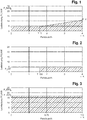
- Fig. 1 is the first charging strategy "basic protection with ramp” shown.
- the charging power P (t) is maintained at the level of the basic backup power P_GS at the beginning of the charging process, so that a maximum possible power increase can be achieved as a negative control power (control potential) during the parking period.
- the charging power P (t) becomes greater with increasing parking time from a ramp start time T_X increases continuously with a linear increase until the peak power P_X is reached at the end time of the parking duration T_K.
- the route describing this linear increase is intended to go in an imaginary extension through the origin of the coordinate system on which the loading plan is based.
- the slope of the straight line is predetermined by the increased amount of energy associated with the rise, with the ramp start time T_X and the peak power P_X at the end time of the parking duration T_K being the intersection with the line of the basic backup power P_GS.
- a customer parks the electric vehicle with an estimated parking time T_K of four hours to receive the desired amount of energy E_K of 25 kWh.
- T_K parking time
- P_GS basic backup power
- the "basic protection with ramp” strategy starts the charging with the basic protection power P_GS of 4.14 kW and retains this value as charging power P (t) up to the ramp start time T_X. From the ramp start time T_X, the charging power P (t) is increased following a linear increase following the peak power P_X at the end time of the parking duration T_K.
- the peak power P_X at the end time of the parking duration T_K can exceed the value of the maximum charging power P_MAX.
- the charging power P (t) is limited by the technical characteristics of the charging station and the charging control unit to the value of the maximum charging power P _MAX. It is therefore not possible for physical reasons to transmit the calculated peak power P_X. Instead of the charging strategy “basic protection with ramp” the strategy "average value" is used.
- Fig. 2 shows a loading plan according to the second charging strategy "deferred basic security”.
- the average charging power P_AVG is less than the basic backup power P_GS, the amount of energy to be supplied is to be distributed over a shorter period of time than the parking time T_K, since the basic backup power P_GS represents a lower limit for the charging power P (t) which is not can be fallen below.
- the charge start is shifted to a later-lying basic backup start time T_GS, from which the desired amount of energy E_K is reached by the basic backup power P_GS over a remaining parking time.
- T_GS T_K - e - K / P_GS ,
- the customer parks the electric vehicle with an estimated parking time T_K of four hours to receive the desired amount of energy E_K of 10 kWh.
- the average charging power P_AVG is thus 2.5 kW and is below the value of the three-phase basic backup power P_GS of 4.14 kW.
- Fig. 3 a loading plan according to the third charging strategy "mean" is shown.
- the average charging power P_AVG is greater than the maximum charging power P_MAX, the desired amount of energy can not be achieved, or the customer's target can not be met. Thus, no negative control power can be provided.
- the maximum possible amount of energy is provided by transmitting the maximum charging power P_MAX during the parking time T_K.
- the customer parks the electric vehicle with an estimated parking duration T_K of one and a half hours to receive the desired amount of energy E_K of 25 kWh.
- the charging device of the electric vehicle has a three-phase charging control unit with a power of 22 kW.
- the maximum charging power P_MAX (upper power limit) is the power of the charging control unit.
- the average charging power P_AVG is 16.67 kW. It is thus between the basic fuse power P_GS of 4.14 kW and the maximum charging power P_MAX of 22 kW.
- Fig. 4 shows a decision flow chart for creating a loading plan.
- the basic backup power P_GS is first determined as the lower power limit and the maximum charging power P_MAX as the upper power limit.
- the smallest possible charging power is made available to the electric vehicle at the beginning of the charging process. Based on the power consumption, the number of outer conductor used by the vehicle and, in turn, the value of the basic backup power P_GS can be determined.
- the vehicle is then provided with the greatest possible charging power for determining the upper power limit. Based on the power consumption, the maximum charging power P_MAX is determined.
- a first condition it is examined whether the first charging strategy "basic protection with ramp” can be used. For this purpose, it must be checked whether the desired amount of energy E_K is greater than the product of the anticipated parking time T_K multiplied by the basic backup power P_GS.
- the second charging strategy of the deferred basic security for the creation of the charging plan must be used in order not to fall below the basic backup power P_GS.
- the third charging strategy "mean value” is applied.
- the average charging power P_AVG is then calculated from the desired amount of energy E_K and the parking time T_K.
- Fig. 5 shows a theoretical loading plan with control limits.
- the control area shows the negative control power over time.
- the lower control limit is determined by the basic backup power P_GS or the charging power P (t) determined by the charging schedule.
- the lower control limit can assume the value zero, for example when the charging process is delayed, but a power increase from the value zero is only possible at or above the basic backup power P_GS.
- the upper control limit of the charging power is the technical maximum, described by the maximum charging power P_MAX, which is limited by the charging connection cable, circuit breaker or charging controller.
- the diagram shows hatched the control range in any charging plan with a basic backup power of 4.14 kW and the maximum charging power P_MAX of 22 kW.
- the loading plan complies with customer specifications, whereby control power is provided between planned charging power and maximum charging power.
- a charging station is equipped with the method according to the invention, thus the charging plan is known, information about the available negative control power can be transmitted directly to the energy supplier or a third party by means of any suitable communication interface.
- the data from several decentralized charging stations can be collected centrally in a virtual power plant. This can be scaled accordingly so that realistically control power can be provided down to the megawatt range in the power grid.
- Every single charging station operator can become a supplier contact the operator of the virtual power plant.
- the charging station will connect to the server of the power plant and ask at the beginning of each load on the server to initiate a power control session. The session is maintained for the duration of the loading process.
- the charging station records the vehicle data and creates the charging plan as described.
- the loading plan is transmitted to the virtual power plant.
- the power output is thus defined over the entire time of the charging process.
- the vehicle is loaded based on the performance curve defined in the loading plan.
- the desired amount of energy is ensured in the vehicle.
- the virtual power station has the option of increasing the charging power specifically up to P_MAX and is now using the negative balancing power.
- a session with the virtual power plant is terminated when the vehicle has loaded the desired amount of energy increase corresponding amount of energy.
- a session can also be terminated if the loading process has been interrupted.
- the charging process can be interrupted manually, for example, by the vehicle owner, if he wants to leave the charging station before the expected parking time expires.
Landscapes
- Engineering & Computer Science (AREA)
- Power Engineering (AREA)
- Transportation (AREA)
- Mechanical Engineering (AREA)
- Life Sciences & Earth Sciences (AREA)
- Sustainable Development (AREA)
- Sustainable Energy (AREA)
- Charge And Discharge Circuits For Batteries Or The Like (AREA)
- Electric Propulsion And Braking For Vehicles (AREA)
Applications Claiming Priority (1)
| Application Number | Priority Date | Filing Date | Title |
|---|---|---|---|
| DE102018104577.8A DE102018104577B4 (de) | 2018-02-28 | 2018-02-28 | Verfahren zur Laststeuerung einer Ladestation für ein Elektrofahrzeug |
Publications (2)
| Publication Number | Publication Date |
|---|---|
| EP3533660A1 true EP3533660A1 (fr) | 2019-09-04 |
| EP3533660B1 EP3533660B1 (fr) | 2020-11-11 |
Family
ID=65324274
Family Applications (1)
| Application Number | Title | Priority Date | Filing Date |
|---|---|---|---|
| EP19155580.4A Active EP3533660B1 (fr) | 2018-02-28 | 2019-02-05 | Procédé de commande de charge d'une station de charge pour un véhicule électrique |
Country Status (4)
| Country | Link |
|---|---|
| US (1) | US11097630B2 (fr) |
| EP (1) | EP3533660B1 (fr) |
| CN (1) | CN110203100B (fr) |
| DE (1) | DE102018104577B4 (fr) |
Families Citing this family (5)
| Publication number | Priority date | Publication date | Assignee | Title |
|---|---|---|---|---|
| CN111497668B (zh) * | 2020-05-19 | 2022-02-22 | 广东电网有限责任公司 | 车辆充电管理方法、装置、计算机设备和存储介质 |
| JP7380429B2 (ja) * | 2020-06-01 | 2023-11-15 | トヨタ自動車株式会社 | バーチャルパワープラントの制御装置 |
| CN113173098B (zh) * | 2021-04-25 | 2024-01-30 | 浙江吉利控股集团有限公司 | 充电模块的均衡控制方法、控制装置、充电桩及存储介质 |
| CN113173097A (zh) * | 2021-06-09 | 2021-07-27 | 国网北京市电力公司 | 充电方法及装置、非易失性存储介质、处理器 |
| CN114228544B (zh) * | 2021-12-24 | 2023-08-29 | 绿能慧充数字技术有限公司 | 一种充电桩充电模块均衡化的分配方法及系统 |
Citations (5)
| Publication number | Priority date | Publication date | Assignee | Title |
|---|---|---|---|---|
| DE102009043380A1 (de) | 2009-09-29 | 2011-04-07 | Ewe Ag | Unidirektionales V2G |
| WO2012095129A2 (fr) * | 2011-01-15 | 2012-07-19 | Daimler Ag | Procédé pour charger une batterie de véhicule |
| WO2013023695A1 (fr) * | 2011-08-17 | 2013-02-21 | Siemens Aktiengesellschaft | Station de charge |
| DE112012005488T5 (de) * | 2011-12-27 | 2014-10-02 | Mitsubishi Electric Corporation | Energiemanagementsystem |
| DE112014001783T5 (de) * | 2013-04-01 | 2015-12-10 | Mitsubishi Electric Corporation | Verfahren zum Ändern eines Ladeplans, Fahrzeug, Ladesteuervorrichtung und Informationseingabe-/Informationsausgabevorrichtung |
Family Cites Families (12)
| Publication number | Priority date | Publication date | Assignee | Title |
|---|---|---|---|---|
| WO2010094302A1 (fr) * | 2009-02-18 | 2010-08-26 | Siemens Aktiengesellschaft | Transmission d'énergie électrique entre un véhicule électrique et un réseau de distribution d'énergie |
| DE102010029118A1 (de) * | 2010-05-19 | 2011-11-24 | Bayerische Motoren Werke Aktiengesellschaft | Verfahren und Vorrichtung zum Betreiben zumindest eines Kraftfahrzeugenergiespeichers |
| CN102130478B (zh) * | 2011-01-21 | 2013-01-16 | 清华大学 | 电动汽车充电站协调充电控制方法 |
| JP5214764B2 (ja) * | 2011-03-25 | 2013-06-19 | 株式会社東芝 | 電気自動車充電スケジューリングシステム |
| US9718371B2 (en) * | 2011-06-30 | 2017-08-01 | International Business Machines Corporation | Recharging of battery electric vehicles on a smart electrical grid system |
| JP6035341B2 (ja) * | 2011-09-29 | 2016-11-30 | エヌイーシー ヨーロッパ リミテッドNec Europe Ltd. | 電気自動車を充電する方法およびシステム |
| RU2633407C2 (ru) * | 2012-02-13 | 2017-10-12 | Эксенчер Глоубл Сервисиз Лимитед | Распределенный интеллект электрического транспортного средства |
| CA2908222A1 (fr) * | 2012-03-28 | 2013-10-03 | Aerovironment, Inc. | Systeme et procede de charge repondant a la frequence |
| CN104253470B (zh) * | 2014-09-25 | 2017-05-03 | 许继电气股份有限公司 | 电动汽车与电网互动协调的有序充电控制方法 |
| FR3045193B1 (fr) * | 2015-12-10 | 2022-06-03 | Schneider Electric Ind Sas | Procede de gestion en energie d'une station de recharge de vehicules electriques |
| DE102016215332A1 (de) * | 2016-08-17 | 2018-02-22 | Bayerische Motoren Werke Aktiengesellschaft | Verfahren zur Steuerung des elektrischen Ladens einer Gruppe von Fahrzeugen |
| CN106487086B (zh) * | 2016-11-25 | 2019-03-22 | 国网江苏省电力公司扬州供电公司 | 一种含电动汽车充放电管理的直流微网协调控制方法 |
-
2018
- 2018-02-28 DE DE102018104577.8A patent/DE102018104577B4/de not_active Expired - Fee Related
-
2019
- 2019-02-05 EP EP19155580.4A patent/EP3533660B1/fr active Active
- 2019-02-26 US US16/285,727 patent/US11097630B2/en active Active
- 2019-02-28 CN CN201910149579.0A patent/CN110203100B/zh active Active
Patent Citations (5)
| Publication number | Priority date | Publication date | Assignee | Title |
|---|---|---|---|---|
| DE102009043380A1 (de) | 2009-09-29 | 2011-04-07 | Ewe Ag | Unidirektionales V2G |
| WO2012095129A2 (fr) * | 2011-01-15 | 2012-07-19 | Daimler Ag | Procédé pour charger une batterie de véhicule |
| WO2013023695A1 (fr) * | 2011-08-17 | 2013-02-21 | Siemens Aktiengesellschaft | Station de charge |
| DE112012005488T5 (de) * | 2011-12-27 | 2014-10-02 | Mitsubishi Electric Corporation | Energiemanagementsystem |
| DE112014001783T5 (de) * | 2013-04-01 | 2015-12-10 | Mitsubishi Electric Corporation | Verfahren zum Ändern eines Ladeplans, Fahrzeug, Ladesteuervorrichtung und Informationseingabe-/Informationsausgabevorrichtung |
Also Published As
| Publication number | Publication date |
|---|---|
| DE102018104577A1 (de) | 2019-08-29 |
| US11097630B2 (en) | 2021-08-24 |
| CN110203100B (zh) | 2022-12-30 |
| CN110203100A (zh) | 2019-09-06 |
| EP3533660B1 (fr) | 2020-11-11 |
| US20190263285A1 (en) | 2019-08-29 |
| DE102018104577B4 (de) | 2019-11-14 |
Similar Documents
| Publication | Publication Date | Title |
|---|---|---|
| DE102018104577B4 (de) | Verfahren zur Laststeuerung einer Ladestation für ein Elektrofahrzeug | |
| EP2465177B1 (fr) | Commande de stations de charge | |
| DE102011008676A1 (de) | System und Verfahren zum Aufladen von Batterien von Fahrzeugen | |
| WO2012095129A2 (fr) | Procédé pour charger une batterie de véhicule | |
| WO2019242928A1 (fr) | Procédé de configuration d'un système de charge et système de charge pour charger l'accumulateur d'énergie électrique d'un véhicule | |
| DE102011008674A1 (de) | Verfahren zum Aufladen einer in einem Fahrzeug angeordneten Batterie | |
| DE102012210448B4 (de) | Elektro- oder Hybridfahrzeug mit einem ein mehrstufiges Stromversorgungssystem umfassenden Fahrzeugbatterieladegerät | |
| WO2012163396A1 (fr) | Limitation de la puissance ou de l'intensité de courant électrique dans des dispositifs de charge | |
| EP3544145B1 (fr) | Procédé de charge des consommateurs électriques | |
| EP2569840A2 (fr) | Dispositif de commutation | |
| WO2002025794A1 (fr) | Procede de regulation de la tension d'un generateur dans une automobile | |
| EP3442823B1 (fr) | Véhicule électrique à récupération d'énergie et apte à fournir une puissance de régulation | |
| EP3336998B1 (fr) | Installation auxiliaire d'alimentation, convertisseur pour une installation auxiliaire d'alimentation ainsi que procédé de fonctionnement d'une installation auxiliaire d'alimentation | |
| EP3146605A1 (fr) | Procédé permettant de faire fonctionner un réseau de bord d'un véhicule automobile et véhicule automobile | |
| WO2016045925A1 (fr) | Dispositif d'accumulation d'énergie destiné à un véhicule automobile et procédé permettant de faire fonctionner un dispositif d'accumulation d'énergie | |
| DE102016202813B4 (de) | Verfahren zur Steuerung des elektrischen Ladens einer Gruppe von Fahrzeugen | |
| WO2020260615A1 (fr) | Procédé et système de coordination d'opérations de charge pour des véhicules électriques | |
| EP3549814B1 (fr) | Procédé d'attribution des informations de connexion et dispositif de charge | |
| EP1143591B1 (fr) | Procédé et dispositif pour commander le fonctionnement en parallèle de convertisseurs de courant continu à courant continu | |
| DE102018206506A1 (de) | Verfahren und Steuereinheit zum Betreiben eines Ladesystems | |
| DE202017006971U1 (de) | Ladestation zum Übertragen von elektrischer Leistung | |
| WO2020229073A1 (fr) | Dispositif, procédé et câble pour injecter de l'énergie électrique dans un réseau d'énergie faisant appel à un accumulateur d'énergie mobile | |
| EP3624290A1 (fr) | Procédé et dispositif de commande destiné au fonctionnement d'un réseau de distribution d'énergie électrique | |
| EP3549812A1 (fr) | Système de charge et procédé de charge d'un accumulateur d'énergie électrique respectif d'une pluralité de véhicules automobiles ainsi que dispositif de charge stationnaire et véhicule automobile | |
| DE102005025954A1 (de) | Ladesystem für Batterien sowie Verfahren zum Betrieb eines Ladesystems für Batterien |
Legal Events
| Date | Code | Title | Description |
|---|---|---|---|
| PUAI | Public reference made under article 153(3) epc to a published international application that has entered the european phase |
Free format text: ORIGINAL CODE: 0009012 |
|
| STAA | Information on the status of an ep patent application or granted ep patent |
Free format text: STATUS: THE APPLICATION HAS BEEN PUBLISHED |
|
| AK | Designated contracting states |
Kind code of ref document: A1 Designated state(s): AL AT BE BG CH CY CZ DE DK EE ES FI FR GB GR HR HU IE IS IT LI LT LU LV MC MK MT NL NO PL PT RO RS SE SI SK SM TR |
|
| AX | Request for extension of the european patent |
Extension state: BA ME |
|
| STAA | Information on the status of an ep patent application or granted ep patent |
Free format text: STATUS: REQUEST FOR EXAMINATION WAS MADE |
|
| 17P | Request for examination filed |
Effective date: 20200107 |
|
| RBV | Designated contracting states (corrected) |
Designated state(s): AL AT BE BG CH CY CZ DE DK EE ES FI FR GB GR HR HU IE IS IT LI LT LU LV MC MK MT NL NO PL PT RO RS SE SI SK SM TR |
|
| GRAP | Despatch of communication of intention to grant a patent |
Free format text: ORIGINAL CODE: EPIDOSNIGR1 |
|
| STAA | Information on the status of an ep patent application or granted ep patent |
Free format text: STATUS: GRANT OF PATENT IS INTENDED |
|
| INTG | Intention to grant announced |
Effective date: 20200603 |
|
| GRAS | Grant fee paid |
Free format text: ORIGINAL CODE: EPIDOSNIGR3 |
|
| GRAA | (expected) grant |
Free format text: ORIGINAL CODE: 0009210 |
|
| STAA | Information on the status of an ep patent application or granted ep patent |
Free format text: STATUS: THE PATENT HAS BEEN GRANTED |
|
| AK | Designated contracting states |
Kind code of ref document: B1 Designated state(s): AL AT BE BG CH CY CZ DE DK EE ES FI FR GB GR HR HU IE IS IT LI LT LU LV MC MK MT NL NO PL PT RO RS SE SI SK SM TR |
|
| REG | Reference to a national code |
Ref country code: GB Ref legal event code: FG4D Free format text: NOT ENGLISH |
|
| REG | Reference to a national code |
Ref country code: CH Ref legal event code: EP |
|
| REG | Reference to a national code |
Ref country code: AT Ref legal event code: REF Ref document number: 1333134 Country of ref document: AT Kind code of ref document: T Effective date: 20201115 |
|
| REG | Reference to a national code |
Ref country code: DE Ref legal event code: R096 Ref document number: 502019000379 Country of ref document: DE |
|
| REG | Reference to a national code |
Ref country code: IE Ref legal event code: FG4D Free format text: LANGUAGE OF EP DOCUMENT: GERMAN |
|
| REG | Reference to a national code |
Ref country code: SE Ref legal event code: TRGR |
|
| REG | Reference to a national code |
Ref country code: NL Ref legal event code: MP Effective date: 20201111 |
|
| PG25 | Lapsed in a contracting state [announced via postgrant information from national office to epo] |
Ref country code: RS Free format text: LAPSE BECAUSE OF FAILURE TO SUBMIT A TRANSLATION OF THE DESCRIPTION OR TO PAY THE FEE WITHIN THE PRESCRIBED TIME-LIMIT Effective date: 20201111 Ref country code: PT Free format text: LAPSE BECAUSE OF FAILURE TO SUBMIT A TRANSLATION OF THE DESCRIPTION OR TO PAY THE FEE WITHIN THE PRESCRIBED TIME-LIMIT Effective date: 20210311 Ref country code: FI Free format text: LAPSE BECAUSE OF FAILURE TO SUBMIT A TRANSLATION OF THE DESCRIPTION OR TO PAY THE FEE WITHIN THE PRESCRIBED TIME-LIMIT Effective date: 20201111 Ref country code: NO Free format text: LAPSE BECAUSE OF FAILURE TO SUBMIT A TRANSLATION OF THE DESCRIPTION OR TO PAY THE FEE WITHIN THE PRESCRIBED TIME-LIMIT Effective date: 20210211 Ref country code: GR Free format text: LAPSE BECAUSE OF FAILURE TO SUBMIT A TRANSLATION OF THE DESCRIPTION OR TO PAY THE FEE WITHIN THE PRESCRIBED TIME-LIMIT Effective date: 20210212 |
|
| PG25 | Lapsed in a contracting state [announced via postgrant information from national office to epo] |
Ref country code: BG Free format text: LAPSE BECAUSE OF FAILURE TO SUBMIT A TRANSLATION OF THE DESCRIPTION OR TO PAY THE FEE WITHIN THE PRESCRIBED TIME-LIMIT Effective date: 20210211 Ref country code: PL Free format text: LAPSE BECAUSE OF FAILURE TO SUBMIT A TRANSLATION OF THE DESCRIPTION OR TO PAY THE FEE WITHIN THE PRESCRIBED TIME-LIMIT Effective date: 20201111 Ref country code: LV Free format text: LAPSE BECAUSE OF FAILURE TO SUBMIT A TRANSLATION OF THE DESCRIPTION OR TO PAY THE FEE WITHIN THE PRESCRIBED TIME-LIMIT Effective date: 20201111 Ref country code: IS Free format text: LAPSE BECAUSE OF FAILURE TO SUBMIT A TRANSLATION OF THE DESCRIPTION OR TO PAY THE FEE WITHIN THE PRESCRIBED TIME-LIMIT Effective date: 20210311 |
|
| REG | Reference to a national code |
Ref country code: LT Ref legal event code: MG9D |
|
| PG25 | Lapsed in a contracting state [announced via postgrant information from national office to epo] |
Ref country code: HR Free format text: LAPSE BECAUSE OF FAILURE TO SUBMIT A TRANSLATION OF THE DESCRIPTION OR TO PAY THE FEE WITHIN THE PRESCRIBED TIME-LIMIT Effective date: 20201111 |
|
| PG25 | Lapsed in a contracting state [announced via postgrant information from national office to epo] |
Ref country code: SK Free format text: LAPSE BECAUSE OF FAILURE TO SUBMIT A TRANSLATION OF THE DESCRIPTION OR TO PAY THE FEE WITHIN THE PRESCRIBED TIME-LIMIT Effective date: 20201111 Ref country code: SM Free format text: LAPSE BECAUSE OF FAILURE TO SUBMIT A TRANSLATION OF THE DESCRIPTION OR TO PAY THE FEE WITHIN THE PRESCRIBED TIME-LIMIT Effective date: 20201111 Ref country code: CZ Free format text: LAPSE BECAUSE OF FAILURE TO SUBMIT A TRANSLATION OF THE DESCRIPTION OR TO PAY THE FEE WITHIN THE PRESCRIBED TIME-LIMIT Effective date: 20201111 Ref country code: EE Free format text: LAPSE BECAUSE OF FAILURE TO SUBMIT A TRANSLATION OF THE DESCRIPTION OR TO PAY THE FEE WITHIN THE PRESCRIBED TIME-LIMIT Effective date: 20201111 Ref country code: LT Free format text: LAPSE BECAUSE OF FAILURE TO SUBMIT A TRANSLATION OF THE DESCRIPTION OR TO PAY THE FEE WITHIN THE PRESCRIBED TIME-LIMIT Effective date: 20201111 Ref country code: RO Free format text: LAPSE BECAUSE OF FAILURE TO SUBMIT A TRANSLATION OF THE DESCRIPTION OR TO PAY THE FEE WITHIN THE PRESCRIBED TIME-LIMIT Effective date: 20201111 |
|
| REG | Reference to a national code |
Ref country code: DE Ref legal event code: R097 Ref document number: 502019000379 Country of ref document: DE |
|
| PG25 | Lapsed in a contracting state [announced via postgrant information from national office to epo] |
Ref country code: DK Free format text: LAPSE BECAUSE OF FAILURE TO SUBMIT A TRANSLATION OF THE DESCRIPTION OR TO PAY THE FEE WITHIN THE PRESCRIBED TIME-LIMIT Effective date: 20201111 |
|
| PLBE | No opposition filed within time limit |
Free format text: ORIGINAL CODE: 0009261 |
|
| STAA | Information on the status of an ep patent application or granted ep patent |
Free format text: STATUS: NO OPPOSITION FILED WITHIN TIME LIMIT |
|
| PG25 | Lapsed in a contracting state [announced via postgrant information from national office to epo] |
Ref country code: MC Free format text: LAPSE BECAUSE OF FAILURE TO SUBMIT A TRANSLATION OF THE DESCRIPTION OR TO PAY THE FEE WITHIN THE PRESCRIBED TIME-LIMIT Effective date: 20201111 |
|
| 26N | No opposition filed |
Effective date: 20210812 |
|
| REG | Reference to a national code |
Ref country code: BE Ref legal event code: MM Effective date: 20210228 |
|
| PG25 | Lapsed in a contracting state [announced via postgrant information from national office to epo] |
Ref country code: IT Free format text: LAPSE BECAUSE OF FAILURE TO SUBMIT A TRANSLATION OF THE DESCRIPTION OR TO PAY THE FEE WITHIN THE PRESCRIBED TIME-LIMIT Effective date: 20201111 Ref country code: LU Free format text: LAPSE BECAUSE OF NON-PAYMENT OF DUE FEES Effective date: 20210205 Ref country code: AL Free format text: LAPSE BECAUSE OF FAILURE TO SUBMIT A TRANSLATION OF THE DESCRIPTION OR TO PAY THE FEE WITHIN THE PRESCRIBED TIME-LIMIT Effective date: 20201111 Ref country code: NL Free format text: LAPSE BECAUSE OF FAILURE TO SUBMIT A TRANSLATION OF THE DESCRIPTION OR TO PAY THE FEE WITHIN THE PRESCRIBED TIME-LIMIT Effective date: 20201111 |
|
| PG25 | Lapsed in a contracting state [announced via postgrant information from national office to epo] |
Ref country code: SI Free format text: LAPSE BECAUSE OF FAILURE TO SUBMIT A TRANSLATION OF THE DESCRIPTION OR TO PAY THE FEE WITHIN THE PRESCRIBED TIME-LIMIT Effective date: 20201111 |
|
| PG25 | Lapsed in a contracting state [announced via postgrant information from national office to epo] |
Ref country code: ES Free format text: LAPSE BECAUSE OF FAILURE TO SUBMIT A TRANSLATION OF THE DESCRIPTION OR TO PAY THE FEE WITHIN THE PRESCRIBED TIME-LIMIT Effective date: 20201111 Ref country code: IE Free format text: LAPSE BECAUSE OF NON-PAYMENT OF DUE FEES Effective date: 20210205 |
|
| PG25 | Lapsed in a contracting state [announced via postgrant information from national office to epo] |
Ref country code: IS Free format text: LAPSE BECAUSE OF FAILURE TO SUBMIT A TRANSLATION OF THE DESCRIPTION OR TO PAY THE FEE WITHIN THE PRESCRIBED TIME-LIMIT Effective date: 20210311 |
|
| PG25 | Lapsed in a contracting state [announced via postgrant information from national office to epo] |
Ref country code: BE Free format text: LAPSE BECAUSE OF NON-PAYMENT OF DUE FEES Effective date: 20210228 |
|
| REG | Reference to a national code |
Ref country code: CH Ref legal event code: PL |
|
| PG25 | Lapsed in a contracting state [announced via postgrant information from national office to epo] |
Ref country code: LI Free format text: LAPSE BECAUSE OF NON-PAYMENT OF DUE FEES Effective date: 20220228 Ref country code: CH Free format text: LAPSE BECAUSE OF NON-PAYMENT OF DUE FEES Effective date: 20220228 |
|
| PGFP | Annual fee paid to national office [announced via postgrant information from national office to epo] |
Ref country code: FR Payment date: 20230217 Year of fee payment: 5 |
|
| PGFP | Annual fee paid to national office [announced via postgrant information from national office to epo] |
Ref country code: SE Payment date: 20230220 Year of fee payment: 5 |
|
| PG25 | Lapsed in a contracting state [announced via postgrant information from national office to epo] |
Ref country code: CY Free format text: LAPSE BECAUSE OF FAILURE TO SUBMIT A TRANSLATION OF THE DESCRIPTION OR TO PAY THE FEE WITHIN THE PRESCRIBED TIME-LIMIT Effective date: 20201111 |
|
| P01 | Opt-out of the competence of the unified patent court (upc) registered |
Effective date: 20230525 |
|
| PG25 | Lapsed in a contracting state [announced via postgrant information from national office to epo] |
Ref country code: HU Free format text: LAPSE BECAUSE OF FAILURE TO SUBMIT A TRANSLATION OF THE DESCRIPTION OR TO PAY THE FEE WITHIN THE PRESCRIBED TIME-LIMIT; INVALID AB INITIO Effective date: 20190205 |
|
| PG25 | Lapsed in a contracting state [announced via postgrant information from national office to epo] |
Ref country code: MK Free format text: LAPSE BECAUSE OF FAILURE TO SUBMIT A TRANSLATION OF THE DESCRIPTION OR TO PAY THE FEE WITHIN THE PRESCRIBED TIME-LIMIT Effective date: 20201111 |
|
| PGFP | Annual fee paid to national office [announced via postgrant information from national office to epo] |
Ref country code: DE Payment date: 20240216 Year of fee payment: 6 Ref country code: GB Payment date: 20240222 Year of fee payment: 6 |