EP3533660A1 - Method for load control of a charging station for an electric vehicle - Google Patents
Method for load control of a charging station for an electric vehicle Download PDFInfo
- Publication number
- EP3533660A1 EP3533660A1 EP19155580.4A EP19155580A EP3533660A1 EP 3533660 A1 EP3533660 A1 EP 3533660A1 EP 19155580 A EP19155580 A EP 19155580A EP 3533660 A1 EP3533660 A1 EP 3533660A1
- Authority
- EP
- European Patent Office
- Prior art keywords
- charging
- power
- charging power
- energy
- strategy
- Prior art date
- Legal status (The legal status is an assumption and is not a legal conclusion. Google has not performed a legal analysis and makes no representation as to the accuracy of the status listed.)
- Granted
Links
Images


Classifications
-
- B—PERFORMING OPERATIONS; TRANSPORTING
- B60—VEHICLES IN GENERAL
- B60L—PROPULSION OF ELECTRICALLY-PROPELLED VEHICLES; SUPPLYING ELECTRIC POWER FOR AUXILIARY EQUIPMENT OF ELECTRICALLY-PROPELLED VEHICLES; ELECTRODYNAMIC BRAKE SYSTEMS FOR VEHICLES IN GENERAL; MAGNETIC SUSPENSION OR LEVITATION FOR VEHICLES; MONITORING OPERATING VARIABLES OF ELECTRICALLY-PROPELLED VEHICLES; ELECTRIC SAFETY DEVICES FOR ELECTRICALLY-PROPELLED VEHICLES
- B60L53/00—Methods of charging batteries, specially adapted for electric vehicles; Charging stations or on-board charging equipment therefor; Exchange of energy storage elements in electric vehicles
- B60L53/10—Methods of charging batteries, specially adapted for electric vehicles; Charging stations or on-board charging equipment therefor; Exchange of energy storage elements in electric vehicles characterised by the energy transfer between the charging station and the vehicle
- B60L53/14—Conductive energy transfer
-
- B—PERFORMING OPERATIONS; TRANSPORTING
- B60—VEHICLES IN GENERAL
- B60L—PROPULSION OF ELECTRICALLY-PROPELLED VEHICLES; SUPPLYING ELECTRIC POWER FOR AUXILIARY EQUIPMENT OF ELECTRICALLY-PROPELLED VEHICLES; ELECTRODYNAMIC BRAKE SYSTEMS FOR VEHICLES IN GENERAL; MAGNETIC SUSPENSION OR LEVITATION FOR VEHICLES; MONITORING OPERATING VARIABLES OF ELECTRICALLY-PROPELLED VEHICLES; ELECTRIC SAFETY DEVICES FOR ELECTRICALLY-PROPELLED VEHICLES
- B60L53/00—Methods of charging batteries, specially adapted for electric vehicles; Charging stations or on-board charging equipment therefor; Exchange of energy storage elements in electric vehicles
- B60L53/60—Monitoring or controlling charging stations
- B60L53/62—Monitoring or controlling charging stations in response to charging parameters, e.g. current, voltage or electrical charge
-
- B—PERFORMING OPERATIONS; TRANSPORTING
- B60—VEHICLES IN GENERAL
- B60L—PROPULSION OF ELECTRICALLY-PROPELLED VEHICLES; SUPPLYING ELECTRIC POWER FOR AUXILIARY EQUIPMENT OF ELECTRICALLY-PROPELLED VEHICLES; ELECTRODYNAMIC BRAKE SYSTEMS FOR VEHICLES IN GENERAL; MAGNETIC SUSPENSION OR LEVITATION FOR VEHICLES; MONITORING OPERATING VARIABLES OF ELECTRICALLY-PROPELLED VEHICLES; ELECTRIC SAFETY DEVICES FOR ELECTRICALLY-PROPELLED VEHICLES
- B60L53/00—Methods of charging batteries, specially adapted for electric vehicles; Charging stations or on-board charging equipment therefor; Exchange of energy storage elements in electric vehicles
- B60L53/60—Monitoring or controlling charging stations
- B60L53/66—Data transfer between charging stations and vehicles
-
- B—PERFORMING OPERATIONS; TRANSPORTING
- B60—VEHICLES IN GENERAL
- B60L—PROPULSION OF ELECTRICALLY-PROPELLED VEHICLES; SUPPLYING ELECTRIC POWER FOR AUXILIARY EQUIPMENT OF ELECTRICALLY-PROPELLED VEHICLES; ELECTRODYNAMIC BRAKE SYSTEMS FOR VEHICLES IN GENERAL; MAGNETIC SUSPENSION OR LEVITATION FOR VEHICLES; MONITORING OPERATING VARIABLES OF ELECTRICALLY-PROPELLED VEHICLES; ELECTRIC SAFETY DEVICES FOR ELECTRICALLY-PROPELLED VEHICLES
- B60L58/00—Methods or circuit arrangements for monitoring or controlling batteries or fuel cells, specially adapted for electric vehicles
- B60L58/10—Methods or circuit arrangements for monitoring or controlling batteries or fuel cells, specially adapted for electric vehicles for monitoring or controlling batteries
- B60L58/12—Methods or circuit arrangements for monitoring or controlling batteries or fuel cells, specially adapted for electric vehicles for monitoring or controlling batteries responding to state of charge [SoC]
-
- H—ELECTRICITY
- H02—GENERATION; CONVERSION OR DISTRIBUTION OF ELECTRIC POWER
- H02J—CIRCUIT ARRANGEMENTS OR SYSTEMS FOR SUPPLYING OR DISTRIBUTING ELECTRIC POWER; SYSTEMS FOR STORING ELECTRIC ENERGY
- H02J3/00—Circuit arrangements for ac mains or ac distribution networks
- H02J3/12—Circuit arrangements for ac mains or ac distribution networks for adjusting voltage in ac networks by changing a characteristic of the network load
- H02J3/14—Circuit arrangements for ac mains or ac distribution networks for adjusting voltage in ac networks by changing a characteristic of the network load by switching loads on to, or off from, network, e.g. progressively balanced loading
-
- H—ELECTRICITY
- H02—GENERATION; CONVERSION OR DISTRIBUTION OF ELECTRIC POWER
- H02J—CIRCUIT ARRANGEMENTS OR SYSTEMS FOR SUPPLYING OR DISTRIBUTING ELECTRIC POWER; SYSTEMS FOR STORING ELECTRIC ENERGY
- H02J3/00—Circuit arrangements for ac mains or ac distribution networks
- H02J3/28—Arrangements for balancing of the load in a network by storage of energy
-
- B—PERFORMING OPERATIONS; TRANSPORTING
- B60—VEHICLES IN GENERAL
- B60L—PROPULSION OF ELECTRICALLY-PROPELLED VEHICLES; SUPPLYING ELECTRIC POWER FOR AUXILIARY EQUIPMENT OF ELECTRICALLY-PROPELLED VEHICLES; ELECTRODYNAMIC BRAKE SYSTEMS FOR VEHICLES IN GENERAL; MAGNETIC SUSPENSION OR LEVITATION FOR VEHICLES; MONITORING OPERATING VARIABLES OF ELECTRICALLY-PROPELLED VEHICLES; ELECTRIC SAFETY DEVICES FOR ELECTRICALLY-PROPELLED VEHICLES
- B60L2240/00—Control parameters of input or output; Target parameters
- B60L2240/80—Time limits
-
- B—PERFORMING OPERATIONS; TRANSPORTING
- B60—VEHICLES IN GENERAL
- B60L—PROPULSION OF ELECTRICALLY-PROPELLED VEHICLES; SUPPLYING ELECTRIC POWER FOR AUXILIARY EQUIPMENT OF ELECTRICALLY-PROPELLED VEHICLES; ELECTRODYNAMIC BRAKE SYSTEMS FOR VEHICLES IN GENERAL; MAGNETIC SUSPENSION OR LEVITATION FOR VEHICLES; MONITORING OPERATING VARIABLES OF ELECTRICALLY-PROPELLED VEHICLES; ELECTRIC SAFETY DEVICES FOR ELECTRICALLY-PROPELLED VEHICLES
- B60L2250/00—Driver interactions
- B60L2250/14—Driver interactions by input of vehicle departure time
-
- B—PERFORMING OPERATIONS; TRANSPORTING
- B60—VEHICLES IN GENERAL
- B60L—PROPULSION OF ELECTRICALLY-PROPELLED VEHICLES; SUPPLYING ELECTRIC POWER FOR AUXILIARY EQUIPMENT OF ELECTRICALLY-PROPELLED VEHICLES; ELECTRODYNAMIC BRAKE SYSTEMS FOR VEHICLES IN GENERAL; MAGNETIC SUSPENSION OR LEVITATION FOR VEHICLES; MONITORING OPERATING VARIABLES OF ELECTRICALLY-PROPELLED VEHICLES; ELECTRIC SAFETY DEVICES FOR ELECTRICALLY-PROPELLED VEHICLES
- B60L2260/00—Operating Modes
- B60L2260/40—Control modes
- B60L2260/50—Control modes by future state prediction
- B60L2260/54—Energy consumption estimation
-
- B—PERFORMING OPERATIONS; TRANSPORTING
- B60—VEHICLES IN GENERAL
- B60L—PROPULSION OF ELECTRICALLY-PROPELLED VEHICLES; SUPPLYING ELECTRIC POWER FOR AUXILIARY EQUIPMENT OF ELECTRICALLY-PROPELLED VEHICLES; ELECTRODYNAMIC BRAKE SYSTEMS FOR VEHICLES IN GENERAL; MAGNETIC SUSPENSION OR LEVITATION FOR VEHICLES; MONITORING OPERATING VARIABLES OF ELECTRICALLY-PROPELLED VEHICLES; ELECTRIC SAFETY DEVICES FOR ELECTRICALLY-PROPELLED VEHICLES
- B60L2260/00—Operating Modes
- B60L2260/40—Control modes
- B60L2260/50—Control modes by future state prediction
- B60L2260/58—Departure time prediction
-
- Y—GENERAL TAGGING OF NEW TECHNOLOGICAL DEVELOPMENTS; GENERAL TAGGING OF CROSS-SECTIONAL TECHNOLOGIES SPANNING OVER SEVERAL SECTIONS OF THE IPC; TECHNICAL SUBJECTS COVERED BY FORMER USPC CROSS-REFERENCE ART COLLECTIONS [XRACs] AND DIGESTS
- Y02—TECHNOLOGIES OR APPLICATIONS FOR MITIGATION OR ADAPTATION AGAINST CLIMATE CHANGE
- Y02B—CLIMATE CHANGE MITIGATION TECHNOLOGIES RELATED TO BUILDINGS, e.g. HOUSING, HOUSE APPLIANCES OR RELATED END-USER APPLICATIONS
- Y02B70/00—Technologies for an efficient end-user side electric power management and consumption
- Y02B70/30—Systems integrating technologies related to power network operation and communication or information technologies for improving the carbon footprint of the management of residential or tertiary loads, i.e. smart grids as climate change mitigation technology in the buildings sector, including also the last stages of power distribution and the control, monitoring or operating management systems at local level
- Y02B70/3225—Demand response systems, e.g. load shedding, peak shaving
-
- Y—GENERAL TAGGING OF NEW TECHNOLOGICAL DEVELOPMENTS; GENERAL TAGGING OF CROSS-SECTIONAL TECHNOLOGIES SPANNING OVER SEVERAL SECTIONS OF THE IPC; TECHNICAL SUBJECTS COVERED BY FORMER USPC CROSS-REFERENCE ART COLLECTIONS [XRACs] AND DIGESTS
- Y02—TECHNOLOGIES OR APPLICATIONS FOR MITIGATION OR ADAPTATION AGAINST CLIMATE CHANGE
- Y02T—CLIMATE CHANGE MITIGATION TECHNOLOGIES RELATED TO TRANSPORTATION
- Y02T10/00—Road transport of goods or passengers
- Y02T10/60—Other road transportation technologies with climate change mitigation effect
- Y02T10/70—Energy storage systems for electromobility, e.g. batteries
-
- Y—GENERAL TAGGING OF NEW TECHNOLOGICAL DEVELOPMENTS; GENERAL TAGGING OF CROSS-SECTIONAL TECHNOLOGIES SPANNING OVER SEVERAL SECTIONS OF THE IPC; TECHNICAL SUBJECTS COVERED BY FORMER USPC CROSS-REFERENCE ART COLLECTIONS [XRACs] AND DIGESTS
- Y02—TECHNOLOGIES OR APPLICATIONS FOR MITIGATION OR ADAPTATION AGAINST CLIMATE CHANGE
- Y02T—CLIMATE CHANGE MITIGATION TECHNOLOGIES RELATED TO TRANSPORTATION
- Y02T10/00—Road transport of goods or passengers
- Y02T10/60—Other road transportation technologies with climate change mitigation effect
- Y02T10/7072—Electromobility specific charging systems or methods for batteries, ultracapacitors, supercapacitors or double-layer capacitors
-
- Y—GENERAL TAGGING OF NEW TECHNOLOGICAL DEVELOPMENTS; GENERAL TAGGING OF CROSS-SECTIONAL TECHNOLOGIES SPANNING OVER SEVERAL SECTIONS OF THE IPC; TECHNICAL SUBJECTS COVERED BY FORMER USPC CROSS-REFERENCE ART COLLECTIONS [XRACs] AND DIGESTS
- Y02—TECHNOLOGIES OR APPLICATIONS FOR MITIGATION OR ADAPTATION AGAINST CLIMATE CHANGE
- Y02T—CLIMATE CHANGE MITIGATION TECHNOLOGIES RELATED TO TRANSPORTATION
- Y02T90/00—Enabling technologies or technologies with a potential or indirect contribution to GHG emissions mitigation
- Y02T90/10—Technologies relating to charging of electric vehicles
- Y02T90/12—Electric charging stations
-
- Y—GENERAL TAGGING OF NEW TECHNOLOGICAL DEVELOPMENTS; GENERAL TAGGING OF CROSS-SECTIONAL TECHNOLOGIES SPANNING OVER SEVERAL SECTIONS OF THE IPC; TECHNICAL SUBJECTS COVERED BY FORMER USPC CROSS-REFERENCE ART COLLECTIONS [XRACs] AND DIGESTS
- Y02—TECHNOLOGIES OR APPLICATIONS FOR MITIGATION OR ADAPTATION AGAINST CLIMATE CHANGE
- Y02T—CLIMATE CHANGE MITIGATION TECHNOLOGIES RELATED TO TRANSPORTATION
- Y02T90/00—Enabling technologies or technologies with a potential or indirect contribution to GHG emissions mitigation
- Y02T90/10—Technologies relating to charging of electric vehicles
- Y02T90/14—Plug-in electric vehicles
-
- Y—GENERAL TAGGING OF NEW TECHNOLOGICAL DEVELOPMENTS; GENERAL TAGGING OF CROSS-SECTIONAL TECHNOLOGIES SPANNING OVER SEVERAL SECTIONS OF THE IPC; TECHNICAL SUBJECTS COVERED BY FORMER USPC CROSS-REFERENCE ART COLLECTIONS [XRACs] AND DIGESTS
- Y02—TECHNOLOGIES OR APPLICATIONS FOR MITIGATION OR ADAPTATION AGAINST CLIMATE CHANGE
- Y02T—CLIMATE CHANGE MITIGATION TECHNOLOGIES RELATED TO TRANSPORTATION
- Y02T90/00—Enabling technologies or technologies with a potential or indirect contribution to GHG emissions mitigation
- Y02T90/10—Technologies relating to charging of electric vehicles
- Y02T90/16—Information or communication technologies improving the operation of electric vehicles
-
- Y—GENERAL TAGGING OF NEW TECHNOLOGICAL DEVELOPMENTS; GENERAL TAGGING OF CROSS-SECTIONAL TECHNOLOGIES SPANNING OVER SEVERAL SECTIONS OF THE IPC; TECHNICAL SUBJECTS COVERED BY FORMER USPC CROSS-REFERENCE ART COLLECTIONS [XRACs] AND DIGESTS
- Y04—INFORMATION OR COMMUNICATION TECHNOLOGIES HAVING AN IMPACT ON OTHER TECHNOLOGY AREAS
- Y04S—SYSTEMS INTEGRATING TECHNOLOGIES RELATED TO POWER NETWORK OPERATION, COMMUNICATION OR INFORMATION TECHNOLOGIES FOR IMPROVING THE ELECTRICAL POWER GENERATION, TRANSMISSION, DISTRIBUTION, MANAGEMENT OR USAGE, i.e. SMART GRIDS
- Y04S20/00—Management or operation of end-user stationary applications or the last stages of power distribution; Controlling, monitoring or operating thereof
- Y04S20/20—End-user application control systems
- Y04S20/222—Demand response systems, e.g. load shedding, peak shaving
Definitions
- the invention relates to a method for load control of a charging station for an electric vehicle having an energy store, wherein a charging power is conductively supplied and controlled via a charging connection line.
- the electric vehicles connected to the power grid can thus provide positive control power (feeding energy into the power grid) when regenerated, as well as negative control power (power taken from the power grid) when charging.
- the network operator will not allow any vehicle to feed energy into the grid regardless of location.
- this unidirectional method has the disadvantage that if there is no possibility of charging at the destination entered into a navigation device, the amount of energy for a further destination or for the return route is not taken into account. Furthermore, a more repetitive destination input the driver can not be expected; he will not be able to fully plan his day in the least.
- the present invention is therefore based on the object to provide a method for charging an energy storage of an electric vehicle, which provides the power supply network as large as possible control potential in terms of the amount of energy provided and thereby without jeopardizing the customer target is to be realized in a simple manner.
- control is used herein in an overall sense, which may include both a pure (pre-coupled) control mechanism and a feedback system (control).
- the inventive method is based on the assumption that the electric vehicle is connected via a conductive charging system according to the standard DIN EN 61851-1 with the charging station.
- the charging station is also equipped with a communication interface, but at least with a control unit for entering vehicle and customer-specific data.
- performance-specific data of a charging device of the electric vehicle are detected, in which case the relevant components of the charging device are understood to be, in particular, a charging control device and the energy store.
- an anticipated parking time T_K and a desired amount of energy E_K are recorded in a further step as customer-specific data.
- This information represents the customer's goal, which is to be achieved under the given technical conditions with the aim of providing the largest possible control potential.
- a basic backup power P_GS is determined as the lower power limit, which depends on the technical features of the Charging device of the electric vehicle and the charging station corresponds to a minimum transferable power and their underrun during the charging process, except for an interruption of the power transmission, is not possible.
- a maximum charging power P_MAX is determined as the upper power limit, which results from the maximum transferable power of the charging station, the charging cable or the charging control unit of the electric vehicle.
- a charging plan is created, which describes a time course of the charging power P (t) (charging curve ).
- the charging plan according to the invention follows a charging strategy that specifies the time course of the charging power over the parking period.
- the loading plan is executed according to the chosen charging strategy.
- the inventive method is thus characterized by the fact that only the technical facilities of the charging station are used, which are already codified normative. This advantageously makes it possible to integrate virtually any electric vehicle into the power supply network for the provision of the control power.
- Another technical requirement is only an incompletely filled energy storage of the electric vehicle. In a single charge, the energy storage is used to provide negative control power.
- the customer-specific required to create a loading plan Information is limited to the parking duration and the desired amount of energy.
- the charging station converts this information under the existing technical conditions into a loading plan. Although the charging station has control over the energy flow, it has only limited control options, so that no conflict with the customer target agreement can arise.
- the loading plan has the advantage that it does not come to unwanted power peaks in the power supply in a high traffic volume, such as the daily rush hour.
- the positive effect occurs that the life of the electric vehicle energy storage can be increased.
- the power supply system remains stable in the application of the method according to the invention for load control, because an electric vehicle as energy storage is no longer available, can be compensated for by using an increase in performance at another charging station of the failure.
- the energy flow in the grid can be predicted in advance.
- the method according to the invention and the communication with the network operator or energy supplier are implemented in the charging station.
- the method can be applied independently of the electric vehicle to be charged.
- the charging plan follows a charging strategy that determines the course of the charging power over the specified parking duration with clear power values determined and ensured that at the same time the customer target is achieved.
- a first charging strategy corresponds to a charging strategy "basic protection with ramp” and describes a course of the charging power over the parking period, in which the charging power remains constant from a start time of the parking duration and corresponds to the value of the basic backup power up to a ramp start time. Starting from the ramp start time, starting from the value of the basic backup power, a linear increase of the charging power is followed up to a peak power P_X at the end time of the parking duration.
- the linear increase is determined by a straight line passing through the origin of the loadplan representation.
- a second charging strategy corresponds to a charging strategy "deferred basic security" and describes a course in which the energy transfer is initially delayed until a basic backup start time. From the basic backup start time, the charging power runs over the remaining parking time remaining at the level of the basic backup power until the end of the parking time.
- a third charging strategy corresponds to a charging strategy "average value" and describes a course in which the desired amount of energy is distributed evenly over the parking period, so that a constant over the parking duration average charging power P_AVG results for the time course of the charging power.
- the maximum charging power is supplied over the parking period (only). In this case, the desired amount of energy is not reached within the parking time. A negative control power is not achieved.
- one of the three predefined loading strategies is selected according to a defined decision procedure.
- the charging strategy is used which under the given technical boundary conditions shows the greatest possible potential for the provision of the control power and thereby fulfills the user specifications (customer target).
- the performance descriptive information of the system ie the basic backup power as the lower power limit and the maximum charging power as the upper power limit, as well as the customer-specific data parking duration and the amount of energy required.
- a first condition it is checked whether the desired amount of energy is greater than the product of basic backup power and parking duration. If this condition is not met, the desired amount of energy can be transmitted with a constant charging power corresponding to the basic backup power in a shorter duration than the parking time. The energy transfer will thus start delayed according to the second charging strategy with the value of the basic backup power at a basic backup start time.
- the straight line is calculated with the target direction for the application of the first charging strategy, which predetermines the linear increase of the charging power.
- the slope of the straight line can be determined. From the point of intersection of the straight line with the line of the basic backup power, the ramp start time and the charging power to be delivered at the end time of the parking duration result as peak power.
- the second charging strategy can not be tracked because of the foreseeable excess of power, and the third charging strategy "average value" is used.
- the possibility of permanent charging with the basic fuse ensures that the electric vehicle has a minimum amount of energy available even with a shorter parking time - except for the charging strategy of the deferred basic security. This is used in the case, if a very small amount of energy in a longer time is desired. Here it is assumed that it is due to the small amount of energy just a recharge. The vehicle already has a charged amount of energy, so there is no mobility problem here.
- the storage capacity of the energy storage, the state of charge of the energy storage and performance-specific data of the installed in the electric vehicle charging control unit are detected.
- the acquisition of the performance-specific data of the charging device of the electric vehicle and / or the customer-specific data takes place either via an established communication channel or by manual inputs of the user.
- the communication channel between the charge control unit of the electric vehicle and the charging station can be designed according to the standard IEC 15118 as "power line communication".
- the performance-specific data of the charging control unit installed in the electric vehicle is recorded by means of a charging method in the following steps: starting a charging process with a charging power that corresponds to a minimum value of a current flow in an outer conductor, measuring a first charging power, determining the basic fuse Power as the lower power limit and the number of outer conductors used for charging from the measured first charging power, increasing the charging power to a maximum available charging power, which is predetermined by the charging station and measuring a second charging power. If the measured second charging power is greater than the basic backup power, the measured second charging power is used as the maximum charging power. Otherwise, the maximum charging power is equivalent to the basic backup power.
- the lower and the upper power limit can be determined if there is no possibility of querying the performance-specific data of the charging device of the electric vehicle.
- the acquisition of the customer-specific data can take place in such a way that the user manually enters at the charging station a desired amount of energy corresponding to the desired range increase as well as a desired departure time for calculating the estimated parking duration.
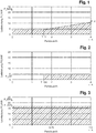
- Fig. 1 is the first charging strategy "basic protection with ramp” shown.
- the charging power P (t) is maintained at the level of the basic backup power P_GS at the beginning of the charging process, so that a maximum possible power increase can be achieved as a negative control power (control potential) during the parking period.
- the charging power P (t) becomes greater with increasing parking time from a ramp start time T_X increases continuously with a linear increase until the peak power P_X is reached at the end time of the parking duration T_K.
- the route describing this linear increase is intended to go in an imaginary extension through the origin of the coordinate system on which the loading plan is based.
- the slope of the straight line is predetermined by the increased amount of energy associated with the rise, with the ramp start time T_X and the peak power P_X at the end time of the parking duration T_K being the intersection with the line of the basic backup power P_GS.
- a customer parks the electric vehicle with an estimated parking time T_K of four hours to receive the desired amount of energy E_K of 25 kWh.
- T_K parking time
- P_GS basic backup power
- the "basic protection with ramp” strategy starts the charging with the basic protection power P_GS of 4.14 kW and retains this value as charging power P (t) up to the ramp start time T_X. From the ramp start time T_X, the charging power P (t) is increased following a linear increase following the peak power P_X at the end time of the parking duration T_K.
- the peak power P_X at the end time of the parking duration T_K can exceed the value of the maximum charging power P_MAX.
- the charging power P (t) is limited by the technical characteristics of the charging station and the charging control unit to the value of the maximum charging power P _MAX. It is therefore not possible for physical reasons to transmit the calculated peak power P_X. Instead of the charging strategy “basic protection with ramp” the strategy "average value" is used.
- Fig. 2 shows a loading plan according to the second charging strategy "deferred basic security”.
- the average charging power P_AVG is less than the basic backup power P_GS, the amount of energy to be supplied is to be distributed over a shorter period of time than the parking time T_K, since the basic backup power P_GS represents a lower limit for the charging power P (t) which is not can be fallen below.
- the charge start is shifted to a later-lying basic backup start time T_GS, from which the desired amount of energy E_K is reached by the basic backup power P_GS over a remaining parking time.
- T_GS T_K - e - K / P_GS ,
- the customer parks the electric vehicle with an estimated parking time T_K of four hours to receive the desired amount of energy E_K of 10 kWh.
- the average charging power P_AVG is thus 2.5 kW and is below the value of the three-phase basic backup power P_GS of 4.14 kW.
- Fig. 3 a loading plan according to the third charging strategy "mean" is shown.
- the average charging power P_AVG is greater than the maximum charging power P_MAX, the desired amount of energy can not be achieved, or the customer's target can not be met. Thus, no negative control power can be provided.
- the maximum possible amount of energy is provided by transmitting the maximum charging power P_MAX during the parking time T_K.
- the customer parks the electric vehicle with an estimated parking duration T_K of one and a half hours to receive the desired amount of energy E_K of 25 kWh.
- the charging device of the electric vehicle has a three-phase charging control unit with a power of 22 kW.
- the maximum charging power P_MAX (upper power limit) is the power of the charging control unit.
- the average charging power P_AVG is 16.67 kW. It is thus between the basic fuse power P_GS of 4.14 kW and the maximum charging power P_MAX of 22 kW.
- Fig. 4 shows a decision flow chart for creating a loading plan.
- the basic backup power P_GS is first determined as the lower power limit and the maximum charging power P_MAX as the upper power limit.
- the smallest possible charging power is made available to the electric vehicle at the beginning of the charging process. Based on the power consumption, the number of outer conductor used by the vehicle and, in turn, the value of the basic backup power P_GS can be determined.
- the vehicle is then provided with the greatest possible charging power for determining the upper power limit. Based on the power consumption, the maximum charging power P_MAX is determined.
- a first condition it is examined whether the first charging strategy "basic protection with ramp” can be used. For this purpose, it must be checked whether the desired amount of energy E_K is greater than the product of the anticipated parking time T_K multiplied by the basic backup power P_GS.
- the second charging strategy of the deferred basic security for the creation of the charging plan must be used in order not to fall below the basic backup power P_GS.
- the third charging strategy "mean value” is applied.
- the average charging power P_AVG is then calculated from the desired amount of energy E_K and the parking time T_K.
- Fig. 5 shows a theoretical loading plan with control limits.
- the control area shows the negative control power over time.
- the lower control limit is determined by the basic backup power P_GS or the charging power P (t) determined by the charging schedule.
- the lower control limit can assume the value zero, for example when the charging process is delayed, but a power increase from the value zero is only possible at or above the basic backup power P_GS.
- the upper control limit of the charging power is the technical maximum, described by the maximum charging power P_MAX, which is limited by the charging connection cable, circuit breaker or charging controller.
- the diagram shows hatched the control range in any charging plan with a basic backup power of 4.14 kW and the maximum charging power P_MAX of 22 kW.
- the loading plan complies with customer specifications, whereby control power is provided between planned charging power and maximum charging power.
- a charging station is equipped with the method according to the invention, thus the charging plan is known, information about the available negative control power can be transmitted directly to the energy supplier or a third party by means of any suitable communication interface.
- the data from several decentralized charging stations can be collected centrally in a virtual power plant. This can be scaled accordingly so that realistically control power can be provided down to the megawatt range in the power grid.
- Every single charging station operator can become a supplier contact the operator of the virtual power plant.
- the charging station will connect to the server of the power plant and ask at the beginning of each load on the server to initiate a power control session. The session is maintained for the duration of the loading process.
- the charging station records the vehicle data and creates the charging plan as described.
- the loading plan is transmitted to the virtual power plant.
- the power output is thus defined over the entire time of the charging process.
- the vehicle is loaded based on the performance curve defined in the loading plan.
- the desired amount of energy is ensured in the vehicle.
- the virtual power station has the option of increasing the charging power specifically up to P_MAX and is now using the negative balancing power.
- a session with the virtual power plant is terminated when the vehicle has loaded the desired amount of energy increase corresponding amount of energy.
- a session can also be terminated if the loading process has been interrupted.
- the charging process can be interrupted manually, for example, by the vehicle owner, if he wants to leave the charging station before the expected parking time expires.
Landscapes
- Engineering & Computer Science (AREA)
- Power Engineering (AREA)
- Transportation (AREA)
- Mechanical Engineering (AREA)
- Life Sciences & Earth Sciences (AREA)
- Sustainable Development (AREA)
- Sustainable Energy (AREA)
- Charge And Discharge Circuits For Batteries Or The Like (AREA)
- Electric Propulsion And Braking For Vehicles (AREA)
Abstract
Die Erfindung betrifft ein Verfahren zur Laststeuerung einer Ladestation für ein Elektrofahrzeug mit einem Energiespeicher, wobei eine Ladeleistung konduktiv über eine Ladeanschlussleitung zugeführt und gesteuert wird mit dem Ziel der Bereitstellung eines möglichst großen (Strom-)Regelpotentials, um für das Stromversorgungssystem Netzstabilität zu erreichen.Es werden leistungsspezifische Fahrzeugdaten sowie als kundenspezifische Daten eine voraussichtliche Parkdauer und eine gewünschte Energiemenge erfasst.Auf der Basis der vorgenannten Daten wird ein Ladeplan erstellt, der erfindungsgemäß unterschiedlichen Ladestrategien folgen kann, die den zeitlichen Verlauf der Ladeleistung über die Parkdauer bestimmen.The invention relates to a method for load control of a charging station for an electric vehicle with an energy store, wherein a charging power is conductively supplied and controlled via a charging connection line with the aim of providing the largest possible (current) control potential in order to achieve grid stability for the power supply system On the basis of the aforementioned data, a loading plan is created, which can follow different charging strategies according to the invention, which determine the time course of the charging power over the parking duration.
Description
Die Erfindung betrifft ein Verfahren zur Laststeuerung einer Ladestation für ein Elektrofahrzeug mit einem Energiespeicher, wobei eine Ladeleistung konduktiv über eine Ladeanschlussleitung zugeführt und gesteuert wird.The invention relates to a method for load control of a charging station for an electric vehicle having an energy store, wherein a charging power is conductively supplied and controlled via a charging connection line.
Im Zuge der Energiewende speisen regenerative Energieträger zunehmend mehr Strom in das Stromversorgungsnetz ein. Beispielsweise stammt in Deutschland aktuell fast jede dritte verbrauchte Kilowattstunde aus Wind-, Solar-, Wasser- und Bioenergiekraftwerken. Dies hat zur Folge, dass ein Teil des in Deutschland produzierten Stroms exportiert werden muss, weil landesintern nicht genug Regelpotential (Regelleistung) zur Verfügung steht, um das Stromversorgungsnetz hinsichtlich der Netzfrequenz stabil zu halten.As part of the energy transition, renewable energy sources are increasingly feeding more electricity into the power grid. For example, in Germany almost every third kilowatt hour consumed currently comes from wind, solar, water and bioenergy power plants. As a result, part of the electricity produced in Germany has to be exported because there is not enough regulation potential (control power) available internally to keep the power grid stable in terms of grid frequency.
Der Aufbau eins intelligenten Stromnetzes (smart grid) wird daher stark vorangetrieben. Im Sinne dieses "smart grid(s)" ist vorgesehen, künftig die in Elektrofahrzeugen verbauten Akkus als Energiespeicher für das Stromversorgungsnetz mit zu betrachten.The development of an intelligent power grid (smart grid) is therefore being strongly promoted. In the sense of this "smart grid (s)" it is planned to consider in the future the accumulators installed in electric vehicles as energy storage for the power supply network.
Dies erfordert ein bidirektionales Ladeverfahren, bei dem ein Teil der Speicherkapazität des Fahrzeug-Energiespeichers zum Laden oder Entladen von elektrischer Energie genutzt wird. Liegt ein Energieüberschuss im Stromnetz vor, wird der Fahrzeug-Energiespeicher geladen. Liegt umgekehrt ein Energiemangel vor, wird der Energiespeicher entladen und die gespeicherte Energie in das Stromnetz eingespeist. Die an das Stromversorgungsnetz angeschlossenen Elektrofahrzeuge können somit bei Rückspeisung positive Regelleistung (Einspeisung von Energie in das Stromversorgungsnetz), als auch bei Ladung negative Regelleistung (Energieentnahme aus dem Stromversorgungsnetz) bereitstellen.This requires a bidirectional charging method in which part of the storage capacity of the vehicle energy storage is used for charging or discharging electric power. If there is an excess of energy in the power grid, the vehicle's energy storage is charged. Conversely, if there is a lack of energy, the energy storage is discharged and the stored energy is fed into the grid. The electric vehicles connected to the power grid can thus provide positive control power (feeding energy into the power grid) when regenerated, as well as negative control power (power taken from the power grid) when charging.
Einerseits wird es allerdings nicht im Interesse des Fahrzeughalters liegen, dass das Fahrzeug als sein Eigentum von Dritten als Energiespeicher genutzt wird. Hinzu kommt, dass ein nicht vollgeladener Energiespeicher zu einer reduzierten Reichweite und damit zu Einschränkungen der Mobilität führt.On the one hand, however, it will not be in the interest of the vehicle owner that the vehicle will be used by third parties as energy storage. In addition, an energy store that is not fully charged leads to a reduced range and thus to restrictions in mobility.
Andererseits wird auch im Hinblick auf die Anforderungen an die Qualität des Stromnetzes der Netzbetreiber nicht zulassen, dass jedes beliebige Fahrzeug ortsunabhängig Energie in das Netz einspeisen wird.On the other hand, with regard to the requirements of the quality of the electricity network, the network operator will not allow any vehicle to feed energy into the grid regardless of location.
Als Alternative zur Bereitstellung von Regelleistung mittels eines bidirektionalen Ladeverfahrens wird in der Patent-Offenlegungsschrift
Allerdings weist dieses unidirektionale Verfahren den Nachteil auf, dass, falls an dem in ein Navigationsgerät eingegebenen Zielort keine Lademöglichkeit besteht, die Energiemenge für ein weiteres Ziel oder für den Rückweg nicht mitberücksichtigt wird. Des Weiteren kann eine sich öfter wiederholende Zieleingabe dem Fahrer nicht zugemutet werden; er wird in den wenigsten Fällen seinen Tag vollständig planen können.However, this unidirectional method has the disadvantage that if there is no possibility of charging at the destination entered into a navigation device, the amount of energy for a further destination or for the return route is not taken into account. Furthermore, a more repetitive destination input the driver can not be expected; he will not be able to fully plan his day in the least.
Weiterhin werden Daten von der fahrzeuginternen Kommunikationseinheit mittels Versorgernetzleitungen direkt an den Netzbetreiber gesendet. Dies hat zur Folge, dass es für eine weitreichende Kompatibilität mit verschiedenen Netzbetreibern und Fahrzeughersteller umfangreicher Normungsarbeiten bedarf.Furthermore, data from the in-vehicle communication unit is sent directly to the network operator via utility lines. As a result, extensive compatibility with various network operators and vehicle manufacturers requires extensive standardization work.
Darüber hinaus können bei den bekannten konventionellen Lösungen im Rahmen der unidirektionalen Ladeverfahren, wie beispielsweise der Unterbrechung und Fortsetzung des Ladevorgangs, weitere Probleme auftreten:
- am Ende der Parkzeit ist nicht die gewünschte Energiemenge geladen,
- das Potenzial der Regelleistung wird nicht optimal ausgeschöpft,
- es entsteht ein Mobilitätsproblem für den Fahrzeugführer, falls er früher als geplant mit dem Fahrzeug fahren möchte,
- das angedachte Ladeverfahren ist nur in Verbindung mit bestimmten Fahrzeugausstattungen anwendbar,
- die tatsächliche Regelleistung ist nicht kalkulierbar/planbar,
- zur Abfrage von Parkzeit und Energiemenge müssen unvorteilhafte Eingaben oder Berechnungen getätigt werden.
- at the end of the parking time, the desired amount of energy is not loaded,
- the potential of the balancing power is not optimally exploited,
- A mobility problem arises for the driver if he wants to drive the vehicle earlier than planned.
- the envisaged charging method is only applicable in connection with certain vehicle equipment,
- the actual control power can not be calculated / planned,
- In order to query the parking time and amount of energy disadvantageous inputs or calculations must be made.
Es bleibt somit festzustellen, dass eine praxisgerechte Anwendung der bisherigen Verfahrenslösungen nicht gegeben ist.It remains to be noted that a practical application of the previous process solutions is not given.
Der vorliegenden Erfindung liegt somit die Aufgabe zu Grunde, ein Verfahren zum Laden eines Energiespeichers eines Elektrofahrzeugs anzugeben, welches dem Stromversorgungsnetz ein möglichst großes Regelpotential hinsichtlich der bereitgestellten Energiemenge zur Verfügung stellt und dabei ohne das Kundenziel zu gefährden in einfacher Weise zu realisieren ist.The present invention is therefore based on the object to provide a method for charging an energy storage of an electric vehicle, which provides the power supply network as large as possible control potential in terms of the amount of energy provided and thereby without jeopardizing the customer target is to be realized in a simple manner.
Diese Aufgabe wird durch ein Verfahren mit den Merkmalen nach Anspruch 1 gelöst.This object is achieved by a method having the features of
Der Begriff steuern wird hier in einem übergeordneten Sinn verwendet, der sowohl einen reinen (vorgekoppelten) Steuermechanismus als auch ein rückgekoppeltes System (Regelung) umfassen kann.The term control is used herein in an overall sense, which may include both a pure (pre-coupled) control mechanism and a feedback system (control).
Das erfindungsgemäße Verfahren beruht auf der Annahme, dass das Elektrofahrzeug über ein konduktives Ladesystem gemäß der Norm DIN EN 61851-1 mit der Ladestation verbunden ist. Die Ladestation ist darüber hinaus mit einer Kommunikationsschnittstelle, zumindest aber mit einer Bedieneinheit zur Eingabe von fahrzeug- und kundenspezifischen Daten ausgerüstet.The inventive method is based on the assumption that the electric vehicle is connected via a conductive charging system according to the standard DIN EN 61851-1 with the charging station. The charging station is also equipped with a communication interface, but at least with a control unit for entering vehicle and customer-specific data.
In einem ersten Schritt werden leistungsspezifische Daten einer Ladeeinrichtung des Elektrofahrzeugs erfasst, wobei hier als relevante Baugruppen der Ladeeinrichtung insbesondere ein Ladesteuergerät sowie der Energiespeicher verstanden werden.In a first step, performance-specific data of a charging device of the electric vehicle are detected, in which case the relevant components of the charging device are understood to be, in particular, a charging control device and the energy store.
Neben diesen technischen Fahrzeugdaten werden in einem weiteren Schritt als kundenspezifische Daten eine voraussichtlichen Parkdauer T_K und eine gewünschten Energiemenge E_K erfasst. Diese Angaben stellen das Kundenziel dar, das es unter den gegebenen technischen Voraussetzungen mit dem Ziel der Bereitstellung eines möglichst großen Regelpotentials zu erreichen gilt.In addition to these technical vehicle data, an anticipated parking time T_K and a desired amount of energy E_K are recorded in a further step as customer-specific data. This information represents the customer's goal, which is to be achieved under the given technical conditions with the aim of providing the largest possible control potential.
Weiterhin wird eine Grundsicherungs-Leistung P_GS als untere Leistungsgrenze bestimmt, die abhängig von der technischen Ausstattung der Ladeeinrichtung des Elektrofahrzeugs und der Ladestation einer minimalen übertragbaren Leistung entspricht und deren Unterschreitung im Verlauf des Ladevorgangs, abgesehen von einer Unterbrechung der Energieübertragung, nicht möglich ist.Furthermore, a basic backup power P_GS is determined as the lower power limit, which depends on the technical features of the Charging device of the electric vehicle and the charging station corresponds to a minimum transferable power and their underrun during the charging process, except for an interruption of the power transmission, is not possible.
Zudem wird eine maximale Ladeleistung P_MAX als obere Leistungsgrenze bestimmt, die sich aus der maximal übertragbaren Leistung der Ladestation, des Ladekabels oder des Ladesteuergerätes des Elektrofahrzeugs ergibt.In addition, a maximum charging power P_MAX is determined as the upper power limit, which results from the maximum transferable power of the charging station, the charging cable or the charging control unit of the electric vehicle.
Auf der Basis der vorgenannten Daten, nämlich der leistungsspezifischen Daten der Ladeeinrichtung des Elektrofahrzeugs, der voraussichtlichen Parkdauer und der gewünschten Energiemenge sowie der Grundsicherungs-Leistung und der maximalen Ladeleistung wird ein Ladeplan erstellt, der einen zeitlichen Verlauf der Ladeleistung P(t) beschreibt (Ladeverlauf).On the basis of the aforementioned data, namely the performance-specific data of the charging device of the electric vehicle, the expected parking duration and the desired amount of energy and the basic backup power and the maximum charging power a charging plan is created, which describes a time course of the charging power P (t) (charging curve ).
Dabei folgt der Ladeplan erfindungsgemäß einer Ladestrategie, die den zeitlichen Verlauf der Ladeleistung über die Parkdauer vorgibt.In this case, the charging plan according to the invention follows a charging strategy that specifies the time course of the charging power over the parking period.
Anschließend wird der Ladeplan gemäß der gewählten Ladestrategie ausgeführt.Then the loading plan is executed according to the chosen charging strategy.
Das erfindungsgemäße Verfahren zeichnet sich somit dadurch aus, dass ausschließlich die technischen Einrichtungen der Ladestation genutzt werden, die bereits normativ festgeschrieben sind. Dies ermöglicht in vorteilhafter Weise nahezu jedes beliebige Elektrofahrzeug in das Stromversorgungsnetz zur Bereitstellung der Regelleistung einzubinden.The inventive method is thus characterized by the fact that only the technical facilities of the charging station are used, which are already codified normative. This advantageously makes it possible to integrate virtually any electric vehicle into the power supply network for the provision of the control power.
Weitere technische Voraussetzung ist lediglich ein nicht vollständig gefüllter Energiespeicher des Elektrofahrzeugs. In einem einmaligen Ladevorgang wird der Energiespeicher genutzt, um negative Regelleistung bereitzustellen.Another technical requirement is only an incompletely filled energy storage of the electric vehicle. In a single charge, the energy storage is used to provide negative control power.
Die zur Erstellung eines Ladeplans notwendigen kundenspezifischen Angaben beschränken sich auf die Parkdauer und die gewünschte Energiemenge.The customer-specific required to create a loading plan Information is limited to the parking duration and the desired amount of energy.
Durch die Erfassung der kundenspezifischen Angaben nimmt der Benutzer Einfluss auf den Ladevorgang. Die Ladestation setzt diese Angaben unter den vorhandenen technischen Voraussetzungen in einen Ladeplan um. Dabei besitzt die Ladestation zwar die Kontrolle über den Energiefluss, hat aber nur begrenzte Regelmöglichkeiten, sodass kein Konflikt mit der Kundenzielvereinbarung entstehen kann.By capturing the customer-specific information, the user influences the loading process. The charging station converts this information under the existing technical conditions into a loading plan. Although the charging station has control over the energy flow, it has only limited control options, so that no conflict with the customer target agreement can arise.
Der Ladeplan besitzt den Vorteil, dass es bei einem hohen Verkehrsaufkommen, wie dem täglichen Berufsverkehr, nicht zu ungewollten Leistungsspitzen in der Stromversorgung kommt. Zudem tritt bei der erfindungsgemäßen Bereitstellung der negativen Regelleistung der positive Effekt ein, dass die Lebensdauer des Elektrofahrzeug-Energiespeichers erhöht werden kann.The loading plan has the advantage that it does not come to unwanted power peaks in the power supply in a high traffic volume, such as the daily rush hour. In addition, in the provision of the negative control power according to the invention, the positive effect occurs that the life of the electric vehicle energy storage can be increased.
Das Stromversorgungssystem bleibt bei der Anwendung des erfindungsgemäßen Verfahrens zur Laststeuerung weiterhin stabil, denn sollte ein Elektrofahrzeug als Energiespeicher nicht mehr zur Verfügung stehen, kann mithilfe einer Leistungssteigerung an einer anderen Ladestation der Ausfall kompensiert werden.The power supply system remains stable in the application of the method according to the invention for load control, because an electric vehicle as energy storage is no longer available, can be compensated for by using an increase in performance at another charging station of the failure.
Sind darüber hinaus die Ladepläne eines jeden Elektrofahrzeugs dem Netzbetreiber bekannt, kann der Energiefluss im Netz vorrausschauend prognostiziert werden.In addition, if the charging plans of each electric vehicle are known to the grid operator, the energy flow in the grid can be predicted in advance.
Das erfindungsgemäße Verfahren und die Kommunikation mit dem Netzbetreiber bzw. Energieversorger sind in der Ladestation implementiert. Somit kann das Verfahren unabhängig von dem zu ladenden Elektrofahrzeug angewendet werden.The method according to the invention and the communication with the network operator or energy supplier are implemented in the charging station. Thus, the method can be applied independently of the electric vehicle to be charged.
Im Hinblick auf die Erzielung einer maximal möglichen Regelleistung folgt der Ladeplan dabei einer Ladestrategie, die den Verlauf der Ladeleistung über die angegebene Parkdauer mit eindeutigen Leistungswerten bestimmt und sichergestellt, dass zugleich das Kundenziel erreicht wird.With regard to the achievement of a maximum possible control power, the charging plan follows a charging strategy that determines the course of the charging power over the specified parking duration with clear power values determined and ensured that at the same time the customer target is achieved.
Es werden drei vordefinierte, zur Auswahl stehende Ladestrategien vorgeschlagen.Three predefined charging strategies are available.
Eine erste Ladestrategie entspricht einer Ladestrategie "Grundsicherung mit Rampe" und beschreibt einen Verlauf der Ladeleistung über der Parkdauer, bei dem die Ladeleistung von einem Startzeitpunkt der Parkdauer konstant bleibt und bis zu einem Rampen-Startzeitpunkt dem Wert der Grundsicherungs-Leistung entspricht. Ab dem Rampen-Startzeitpunkt schließt sich von dem Wert der Grundsicherungs-Leistung ausgehend ein linearer Anstieg der Ladeleistung bis auf eine Spitzenleistung P_X zum Endzeitpunkt der Parkdauer an.A first charging strategy corresponds to a charging strategy "basic protection with ramp" and describes a course of the charging power over the parking period, in which the charging power remains constant from a start time of the parking duration and corresponds to the value of the basic backup power up to a ramp start time. Starting from the ramp start time, starting from the value of the basic backup power, a linear increase of the charging power is followed up to a peak power P_X at the end time of the parking duration.
Der lineare Anstieg ist dabei durch eine Gerade bestimmt, welche durch den Ursprung der Ladeplan-Darstellung verläuft.The linear increase is determined by a straight line passing through the origin of the loadplan representation.
Eine zweite Ladestrategie entspricht einer Ladestrategie "Aufgeschobene Grundsicherung" und beschreibt einen Verlauf, bei dem die Energieübertragung bis zu einem Grundsicherungs-Startzeitpunkt zunächst verzögert wird. Ab dem Grundsicherungs-Startzeitpunkt verläuft die Ladeleistung über verbleibende Rest-Parkdauer auf dem Niveau der Grundsicherungs-Leistung bis zum Ablauf der Parkdauer.A second charging strategy corresponds to a charging strategy "deferred basic security" and describes a course in which the energy transfer is initially delayed until a basic backup start time. From the basic backup start time, the charging power runs over the remaining parking time remaining at the level of the basic backup power until the end of the parking time.
Eine dritte Ladestrategie entspricht einer Ladestrategie "Mittelwert" und beschreibt einen Verlauf, bei dem die gewünschte Energiemenge gleichmäßig über die Parkdauer verteilt wird, sodass sich für den zeitlichen Verlauf der Ladeleistung eine über die Parkdauer konstante mittlere Ladeleistung P_AVG ergibt.A third charging strategy corresponds to a charging strategy "average value" and describes a course in which the desired amount of energy is distributed evenly over the parking period, so that a constant over the parking duration average charging power P_AVG results for the time course of the charging power.
Ergibt sich eine mittlere Ladeleistung, die kleiner ist als die Grundsicherungs-Leistung ist, so kann dieser Ladestrategie nicht gefolgt werden, da die Grundsicherungs-Leistung nicht unterschritten werden kann. In diesem Fall ist nach der zweiten Ladestrategie der "Aufgeschobene(n) Grundsicherung" zu verfahren.If the average charging power is smaller than the basic backup power, then this charging strategy can not be followed since the basic backup power can not be undershot. In this case, proceed according to the second charging strategy of the "deferred (n) basic security".
Ergibt sich eine mittlere Ladeleistung, die größer ist als die maximale Ladeleistung, wird über die Parkdauer (nur) die maximale Ladeleistung zugeführt. In diesem Fall wird die gewünschte Energiemenge innerhalb der Parkdauer nicht erreicht. Eine negative Regelleistung wird nicht erreicht.If a mean charging power that is greater than the maximum charging power results, the maximum charging power is supplied over the parking period (only). In this case, the desired amount of energy is not reached within the parking time. A negative control power is not achieved.
Bei der Erstellung des Ladeplans wird nach einem festgelegten Entscheidungs-Ablaufplan gezielt eine der drei vordefinierten Ladestrategien ausgewählt. Als Ergebnis der Entscheidung gelangt diejenige Ladestrategie zur Anwendung, welche bei den gegebenen technischen Randbedingungen das größtmögliche Potenzial zur Bereitstellung der Regelleistung aufzeigt und dabei die Benutzervorgaben (Kundenziel) erfüllt.When creating the loading plan, one of the three predefined loading strategies is selected according to a defined decision procedure. As a result of the decision, the charging strategy is used which under the given technical boundary conditions shows the greatest possible potential for the provision of the control power and thereby fulfills the user specifications (customer target).
Zur Auswahl einer geeigneten Ladestrategie werden die leistungsbeschreibenden Angaben des Systems, also die Grundsicherungs-Leistung als untere Leistungsgrenze und die maximale Ladeleistung als obere Leistungsgrenze, sowie die kundenspezifischen Daten Parkdauer und die Energiemenge benötigt.To select a suitable charging strategy, the performance descriptive information of the system, ie the basic backup power as the lower power limit and the maximum charging power as the upper power limit, as well as the customer-specific data parking duration and the amount of energy required.
In einer ersten Bedingung wird geprüft, ob die gewünschte Energiemenge größer ist als das Produkt aus Grundsicherungs-Leistung und Parkdauer. Ist diese Bedingung nicht erfüllt, kann die gewünschte Energiemenge mit einer der Grundsicherungs-Leistung entsprechenden konstanten Ladeleistung in einer kürzeren Dauer als die Parkdauer übertragen werden. Die Energieübertragung wird somit gemäß der zweiten Ladestrategie verzögert mit dem Wert der Grundsicherungs-Leistung zu einem Grundsicherungs-Startzeitpunkt beginnen.In a first condition, it is checked whether the desired amount of energy is greater than the product of basic backup power and parking duration. If this condition is not met, the desired amount of energy can be transmitted with a constant charging power corresponding to the basic backup power in a shorter duration than the parking time. The energy transfer will thus start delayed according to the second charging strategy with the value of the basic backup power at a basic backup start time.
Ist die erste Bedingung erfüllt, wird mit Zielrichtung auf die Anwendung der ersten Ladestrategie die Gerade berechnet, die den linearen Anstieg der Ladeleistung vorgibt.If the first condition is met, the straight line is calculated with the target direction for the application of the first charging strategy, which predetermines the linear increase of the charging power.
Um das Kundenziel zu erreichen, folgt aus einer Leistung-Zeit-Flächenbetrachtung, dass die durch den linearen Anstieg bewirkte zusätzliche Energie (Dreiecksfläche zwischen der Linie der Grundsicherungs-Leistung und der Geraden) zusammen mit der durch die konstante Grundsicherungs-Leistung bewirkte Energie (Rechteckfläche unter der Linie der Grundsicherungs-Leistung) die gewünschte Energiemenge ergeben muss.In order to reach the customer's goal, it follows from a performance time-area analysis that the additional effect caused by the linear increase Energy (triangular area between the line of the basic protection power and the straight line) together with the energy caused by the constant basic backup power (rectangular area under the line of the basic backup power) must give the desired amount of energy.
Mit der Annahme, dass die Gerade durch den Ursprung des Ladeplans verläuft, kann die Steigung der Geraden bestimmt werden. Aus dem Schnittpunkt der Geraden mit der Linie der Grundsicherungs-Leistung ergeben sich der Rampen-Startzeitpunkt und die zum Endzeitpunkt der Parkdauer zu liefernde Ladeleistung als Spitzenleistung.Assuming that the straight line passes through the origin of the loading plan, the slope of the straight line can be determined. From the point of intersection of the straight line with the line of the basic backup power, the ramp start time and the charging power to be delivered at the end time of the parking duration result as peak power.
In einer zweiten Bedingung wird nun geprüft, ob diese Spitzenleistung größer ist als die maximale Ladeleistung.In a second condition, it is now checked whether this peak power is greater than the maximum charging power.
Ist diese Bedingung nicht erfüllt, erfolgt die Leistungssteuerung ab dem Rampen-Startzeitpunkt gemäß der berechneten Geraden, es wird somit die erste Ladestrategie "Grundsicherung mit Rampe" verfolgt.If this condition is not fulfilled, the power control takes place from the ramp start time according to the calculated straight line, thus the first charging strategy "basic protection with ramp" is tracked.
Ist diese zweite Bedingung hingegen erfüllt, kann die zweite Ladestrategie wegen der absehbaren Leistungsüberschreitung nicht verfolgt werden und es gelangt die dritte Ladestrategie "Mittelwert" zur Anwendung.On the other hand, if this second condition is fulfilled, the second charging strategy can not be tracked because of the foreseeable excess of power, and the third charging strategy "average value" is used.
Die Möglichkeit des dauerhaften Ladens mit der Grundsicherung sorgt zum einen dafür, dass dem Elektrofahrzeug eine Mindest-Energiemenge auch bei einer verkürzten Parkdauer zur Verfügung steht - ausgenommen ist die Ladestrategie der aufgeschobenen Grundsicherung. Diese kommt in dem Fall zum Einsatz, falls eine sehr geringe Energiemenge in einer größeren Zeit gewünscht ist. Hier geht man davon aus, dass es sich aufgrund der geringen Energiemenge nur um eine Nachladung handelt. Das Fahrzeug weist hier bereits eine geladene Energiemenge auf, sodass auch hier kein Mobilitätsproblem auftritt.The possibility of permanent charging with the basic fuse on the one hand ensures that the electric vehicle has a minimum amount of energy available even with a shorter parking time - except for the charging strategy of the deferred basic security. This is used in the case, if a very small amount of energy in a longer time is desired. Here it is assumed that it is due to the small amount of energy just a recharge. The vehicle already has a charged amount of energy, so there is no mobility problem here.
Zudem wird der Benutzer aufgrund eines nicht unterbrochenen Ladevorgangs nicht durch eine Nachricht "Ladevorgang unterbrochen" verunsichert. Dies könnte sonst dazu führen, dass er Ladestationen mit Lastregelung künftig meidet.In addition, the user is not unsettled by a message "Charging interrupted" due to an uninterrupted charging process. Otherwise this could lead to charging stations with load regulation avoid it in the future.
Als leistungsspezifische Daten der Ladeeinrichtung des Elektrofahrzeugs werden die Speicherkapazität des Energiespeichers, der Ladezustand des Energiespeichers und leistungsspezifische Daten des in dem Elektrofahrzeug verbauten Ladesteuergerätes erfasst.As a performance-specific data of the charging device of the electric vehicle, the storage capacity of the energy storage, the state of charge of the energy storage and performance-specific data of the installed in the electric vehicle charging control unit are detected.
Die Erfassung der leistungsspezifischen Daten der Ladeeinrichtung des Elektrofahrzeugs und/oder der kundenspezifischen Daten erfolgt entweder über einen eingerichteten Kommunikationskanal oder geschieht durch manuelle Eingaben des Benutzers. Der Kommunikationskanal zwischen dem Ladesteuergerät des Elektrofahrzeugs und der Ladestation kann gemäß der Norm IEC 15118 als "Power-Line-Communication" ausgeführt sein.The acquisition of the performance-specific data of the charging device of the electric vehicle and / or the customer-specific data takes place either via an established communication channel or by manual inputs of the user. The communication channel between the charge control unit of the electric vehicle and the charging station can be designed according to the standard IEC 15118 as "power line communication".
Falls kein Kommunikationskanal eingerichtet ist, erfolgt das Erfassen der leistungsspezifischen Daten des in dem Elektrofahrzeug verbauten Ladesteuergerätes mittels eines Anladeverfahrens in folgenden Schritten: Starten eines Ladevorgangs mit einer Ladeleistung, die einem Minimalwert eines Stromflusses in einem Außenleiter entspricht, Messen einer ersten Ladeleistung, Ermitteln der Grundsicherungs-Leistung als untere Leistungsgrenze und der Anzahl der zum Laden genutzten Außenleiter aus der gemessenen ersten Ladeleistung, Erhöhen der Ladeleistung auf eine verfügbare größte Ladeleistung, welche durch die Ladestation vorgegeben bzw. begrenzt ist und Messen einer zweiten Ladeleistung. Falls die gemessene zweite Ladeleistung größer als die Grundsicherungs-Leistung ist, wird die gemessene zweite Ladeleistung als maximale Ladeleistung verwendet. Andernfalls ist die maximale Ladeleistung der Grundsicherungs-Leistung gleichzusetzen.If no communication channel is set up, the performance-specific data of the charging control unit installed in the electric vehicle is recorded by means of a charging method in the following steps: starting a charging process with a charging power that corresponds to a minimum value of a current flow in an outer conductor, measuring a first charging power, determining the basic fuse Power as the lower power limit and the number of outer conductors used for charging from the measured first charging power, increasing the charging power to a maximum available charging power, which is predetermined by the charging station and measuring a second charging power. If the measured second charging power is greater than the basic backup power, the measured second charging power is used as the maximum charging power. Otherwise, the maximum charging power is equivalent to the basic backup power.
Auf diese Weise können die untere und die obere Leistungsgrenze ermittelt werden, falls keine Möglichkeit der Abfrage der leistungsspezifischen Daten der Ladeeinrichtung des Elektrofahrzeugs besteht.In this way, the lower and the upper power limit can be determined if there is no possibility of querying the performance-specific data of the charging device of the electric vehicle.
Ebenso kann, falls kein Kommunikationskanal eingerichtet ist, das Erfassen der kundenspezifischen Daten derart erfolgen, dass von dem Benutzer manuell an der Ladestation eine der gewünschten Reichweitenerhöhung entsprechende gewünschte Energiemenge sowie eine gewünschte Abfahrtszeit zur Berechnung der voraussichtlichen Parkdauer eingegeben wird.Likewise, if no communication channel is set up, the acquisition of the customer-specific data can take place in such a way that the user manually enters at the charging station a desired amount of energy corresponding to the desired range increase as well as a desired departure time for calculating the estimated parking duration.
Weitere vorteilhafte Ausgestaltungsmerkmale ergeben sich aus der nachfolgenden Beschreibung und den Zeichnungen, die eine bevorzugte Ausführungsform der Erfindung an Hand von Beispielen erläutern. Es zeigen:
- Fig. 1:
- einen Ladeplan gemäß der ersten Ladestrategie "Grundsicherung mit Rampe",
- Fig. 2:
- einen Ladeplan gemäß der zweiten Ladestrategie "Aufgeschobene Grundsicherung",
- Fig. 3:
- einen Ladeplan gemäß der dritten Ladestrategie "Mittelwert",
- Fig. 4:
- einen Entscheidungs-Ablaufplan zur Erstellung eines Ladeplans und
- Fig. 5:
- einen theoretischen Ladeplan mit Regelgrenzen.
- Fig. 1:
- a loading plan according to the first charging strategy "basic security with ramp",
- Fig. 2:
- a loading plan according to the second loading strategy "deferred basic security",
- 3:
- a loading plan according to the third charging strategy "average",
- 4:
- a decision-making schedule for creating a loading plan and
- Fig. 5:
- a theoretical loading plan with control limits.
In
Die Ladeleistung P(t) wird zu Beginn des Ladevorgangs auf dem Niveau der Grundsicherungs-Leistung P_GS gehalten, sodass eine maximal mögliche Leistungssteigerung als negative Regelleistung (Regelpotential) während der Parkdauer erreichbar ist. Um aber dem Risiko entgegenzuwirken, das Kundenziel alleine durch die Lieferung der Grundsicherungs-Leistung P_GS nicht einhalten zu können, wird die Ladeleistung P(t) ab einem Rampen-Startzeitpunkt T_X mit zunehmender Parkzeit kontinuierlich mit einem linearen Anstieg erhöht, bis die Spitzenleistung P_X am Endzeitpunkt der Parkdauer T_K erreicht wird. Die Strecke, die diesen linearen Anstieg beschreibt, soll dabei in gedachter Verlängerung durch den Ursprung des dem Ladeplan zugrunde liegenden Koordinatensystems gehen. Der Steigung der Geraden ist durch die mit dem Anstieg verbundene, erhöhte Energiemenge vorgegeben, wobei sich als Schnittpunkt mit der Linie der Grundsicherungs-Leistung P_GS der Rampen-Startzeitpunkt T_X sowie die Spitzenleistung P_X am Endzeitpunkt der Parkdauer T_K ergeben.The charging power P (t) is maintained at the level of the basic backup power P_GS at the beginning of the charging process, so that a maximum possible power increase can be achieved as a negative control power (control potential) during the parking period. However, in order to counteract the risk that the customer target can not be met solely by the delivery of the basic backup power P_GS, the charging power P (t) becomes greater with increasing parking time from a ramp start time T_X increases continuously with a linear increase until the peak power P_X is reached at the end time of the parking duration T_K. The route describing this linear increase is intended to go in an imaginary extension through the origin of the coordinate system on which the loading plan is based. The slope of the straight line is predetermined by the increased amount of energy associated with the rise, with the ramp start time T_X and the peak power P_X at the end time of the parking duration T_K being the intersection with the line of the basic backup power P_GS.
Ein Kunde (Benutzer) parkt das Elektrofahrzeug mit einer voraussichtlichen Parkdauer T_K von vier Stunden, um die gewünschten Energiemenge E_K von 25 kWh aufzunehmen. Angenommen sei eine Ladung über eine dreiphasige Lademöglichkeit, wobei sich eine Grundsicherungs-Leistung P_GS von 4.14 kW ergibt - unter der Voraussetzung einer Netzspannung von 230 V und einer Stromstärke von 6 A pro Außenleiter (Phase).A customer (user) parks the electric vehicle with an estimated parking time T_K of four hours to receive the desired amount of energy E_K of 25 kWh. Assuming a charge via a three-phase charging option, resulting in a basic backup power P_GS of 4.14 kW - assuming a mains voltage of 230 V and a current of 6 A per phase (phase).
Die Strategie "Grundsicherung mit Rampe" startet die Aufladung mit der Grundsicherungs-Leistung P_GS von 4.14 kW und behält diesen Wert als Ladeleistung P(t) bis zu dem Rampen-Startzeitpunkt T_X bei. Ab dem Rampen-Startzeitpunkt T_X wird die Ladeleistung P(t) einem linearen Anstieg folgend auf die Spitzenleistung P_X am Endzeitpunkt der Parkdauer T_K erhöht.The "basic protection with ramp" strategy starts the charging with the basic protection power P_GS of 4.14 kW and retains this value as charging power P (t) up to the ramp start time T_X. From the ramp start time T_X, the charging power P (t) is increased following a linear increase following the peak power P_X at the end time of the parking duration T_K.
Mit der Grundsicherungs-Leistung P_GS alleine wird über die Parkdauer T_K hinweg ein Energiebedarf in Höhe von 16.56 kWh gedeckt. Die Fläche des durch die Gerade begrenzten Dreiecks oberhalb der Grundsicherungs-Leistung P_GS entspricht einer zusätzlichen Energiemenge von 8.44 kWh, um insgesamt die gewünschte Energiemenge E_K von 25 kWh zu erreichen.With the basic backup power P_GS alone, an energy requirement of 16.56 kWh is covered over the parking duration T_K. The area of the triangle bounded by the straight line above the basic backup power P_GS corresponds to an additional amount of energy of 8.44 kWh in order to achieve the total desired energy quantity E_K of 25 kWh.
Der Verlauf der Ladeleistung P(t) ändert sich an dem Rampen-Startzeitpunkt T_X=1,51 h und erreicht am Endzeitpunkt der Parkdauer T_K=4 h dabei eine Spitzenleistung P_X von 10.93 kW.The course of the charging power P (t) changes at the ramp start time T_X = 1.51 h and reaches at the end time of the parking time T_K = 4 h while a peak power P_X of 10.93 kW.
Bei der Berechnung der Geraden kann die Spitzenleistung P_X am Endzeitpunkt der Parkdauer T_K den Wert der maximalen Ladeleistung P_MAX übersteigen. Allerdings ist die Ladeleistung P(t) durch die technischen Eigenschaften der Ladestation und des Ladesteuergerätes auf den Wert der maximalen Ladeleistung P _MAX begrenzt. Es ist somit aus physikalischen Gründen nicht möglich, die berechnete Spitzenleistung P_X zu übertragen. Anstelle der Ladestrategie "Grundsicherung mit Rampe" wird daher die Strategie "Mittelwert" angewendet.When calculating the straight line, the peak power P_X at the end time of the parking duration T_K can exceed the value of the maximum charging power P_MAX. However, the charging power P (t) is limited by the technical characteristics of the charging station and the charging control unit to the value of the maximum charging power P _MAX. It is therefore not possible for physical reasons to transmit the calculated peak power P_X. Instead of the charging strategy "basic protection with ramp" the strategy "average value" is used.
Sollte die mittlere Ladeleistung P_AVG kleiner sein als die Grundsicherungs-Leistung P_GS, ist die zu liefernde Energiemenge über einen kürzeren Zeitraum als die Parkdauer T_K zu verteilen, da die Grundsicherungs-Leistung P_GS eine untere Grenze für die Ladeleistung P(t) darstellt, die nicht unterschritten werden kann.If the average charging power P_AVG is less than the basic backup power P_GS, the amount of energy to be supplied is to be distributed over a shorter period of time than the parking time T_K, since the basic backup power P_GS represents a lower limit for the charging power P (t) which is not can be fallen below.
Der Ladungsstart wird auf einen später liegenden Grundsicherungs-Startzeitpunkt T_GS verschoben, ab dem über eine restliche Parkdauer die gewünschte Energiemenge E_K allein durch die Grundsicherungs-Leisung P_GS erreicht wird.The charge start is shifted to a later-lying basic backup start time T_GS, from which the desired amount of energy E_K is reached by the basic backup power P_GS over a remaining parking time.
Der Grundsicherungs-Startzeitpunkt T_GS ergibt sich aus ![]()
![]()
Der Kunde parkt das Elektrofahrzeug mit einer voraussichtlichen Parkdauer T_K von vier Stunden, um die gewünschten Energiemenge E_K von 10 kWh aufzunehmen.The customer parks the electric vehicle with an estimated parking time T_K of four hours to receive the desired amount of energy E_K of 10 kWh.
Die mittlere Ladeleistung P_AVG beträgt somit 2.5 kW und liegt unter dem Wert der dreiphasigen Grundsicherungs-Leistung P_GS von 4.14 kW.The average charging power P_AVG is thus 2.5 kW and is below the value of the three-phase basic backup power P_GS of 4.14 kW.
Der Startzeitpunkt der Ladung wird daher auf den Grundsicherungs-Startzeitpunkt T_GS=1.58 h verzögert, ab dem die Ladung über eine Restparkdauer T_K-T_GS=2.42 h mit der Grundsicherungs-Leistung P_GS=4.14 kW startet, um die gewünschte Energiemenge E_K=10 kWh zu liefern.The starting time of the charge is therefore delayed to the basic fuse start time T_GS = 1.58 h, from which the charge starts over a remaining parking time T_K-T_GS = 2.42 h with the basic backup power P_GS = 4.14 kW to the desired amount of energy E_K = 10 kWh deliver.
In
Zur Bestimmung der mittleren Ladeleistung P_AVG wird die gewünschte Energiemenge E_K gemäß P_AVG=E_K/T_K gleichmäßig über die Parkdauer T_K verteilt.To determine the average charging power P_AVG, the desired amount of energy E_K is distributed uniformly over the parking duration T_K in accordance with P_AVG = E_K / T_K.
Mit dieser mittleren Ladeleistung P_AVG wird über die Parkdauer T_K geladen.With this average charging power P_AVG is charged over the parking time T_K.
Zwei Ausnahmen sind hier zu beachten. Ist die mittlere Ladeleistung P_AVG kleiner als die Grundsicherungs-Leistung P_GS, muss nach der zweiten Ladestrategie der "Aufgeschobene(n) Grundsicherung" verfahren werden, da die Grundsicherungs-Leistung P_GS nicht unterschritten werden kann.Two exceptions should be noted here. If the average charging power P_AVG is smaller than the basic backup power P_GS, then the "deferred (n) basic fuse" must be traversed according to the second charging strategy, since the basic backup power P_GS can not be undershot.
Ist die mittlere Ladeleistung P_AVG größer als die maximale Ladeleistung P_MAX, kann die gewünschte Energiemenge nicht erreicht, bzw. das Kundenziel nicht erfüllt werden. Somit kann auch keine negative Regelleistung zur Verfügung gestellt werden.If the average charging power P_AVG is greater than the maximum charging power P_MAX, the desired amount of energy can not be achieved, or the customer's target can not be met. Thus, no negative control power can be provided.
Es wird die maximal mögliche Energiemenge bereitgestellt, indem die maximale Ladeleistung P_MAX während der Parkdauer T_K übertragen wird.The maximum possible amount of energy is provided by transmitting the maximum charging power P_MAX during the parking time T_K.
Der Kunde parkt das Elektrofahrzeug mit einer voraussichtlichen Parkdauer T_K von eineinhalb Stunden, um die gewünschten Energiemenge E_K von 25 kWh aufzunehmen.The customer parks the electric vehicle with an estimated parking duration T_K of one and a half hours to receive the desired amount of energy E_K of 25 kWh.
Die Ladeeinrichtung des Elektrofahrzeugs verfügt über ein dreiphasiges Ladesteuergerät mit einer Leistung von 22 kW. Als maximale Ladeleistung P_MAX (obere Leistungsgrenze) ist die Leistung des Ladesteuergerätes anzusetzen.The charging device of the electric vehicle has a three-phase charging control unit with a power of 22 kW. The maximum charging power P_MAX (upper power limit) is the power of the charging control unit.
Die mittlere Ladeleistung P_AVG beträgt 16,67 kW. Sie liegt damit zwischen der Grundsicherungs-Leistung P_GS von 4.14 kW und der maximalen Ladeleistung P_MAX von 22 kW.The average charging power P_AVG is 16.67 kW. It is thus between the basic fuse power P_GS of 4.14 kW and the maximum charging power P_MAX of 22 kW.
Ausgehend davon, dass die Benutzerangaben über die gewünschte Energiemenge E_K und die voraussichtliche Parkdauer T_K vorliegen, wird zunächst die Grundsicherungs-Leistung P_GS als untere Leistungsgrenze und die maximale Ladeleistung P_MAX als obere Leistungsgrenze ermittelt.Assuming that the user information about the desired amount of energy E_K and the estimated parking time T_K are present, the basic backup power P_GS is first determined as the lower power limit and the maximum charging power P_MAX as the upper power limit.
Zur Bestimmung der unteren Leistungsgrenze wird dem Elektrofahrzeug zu Beginn des Ladeprozesses die kleinste mögliche Ladeleistung zur Verfügung gestellt. Anhand der Leistungsaufnahme kann die Anzahl der von dem Fahrzeug genutzten Außenleiter und daraus wiederum der Wert der Grundsicherungs-Leistung P_GS bestimmt werden.To determine the lower power limit, the smallest possible charging power is made available to the electric vehicle at the beginning of the charging process. Based on the power consumption, the number of outer conductor used by the vehicle and, in turn, the value of the basic backup power P_GS can be determined.
Ohne den Ladevorgang zu unterbrechen wird dem Fahrzeug anschließend zur Bestimmung der oberen Leistungsgrenze die größte mögliche Ladeleistung zur Verfügung gestellt. Anhand der Leistungsaufnahme wird die maximale Ladeleistung P_MAX bestimmt.Without interrupting the charging process, the vehicle is then provided with the greatest possible charging power for determining the upper power limit. Based on the power consumption, the maximum charging power P_MAX is determined.
Liegen die den Ladeverlauf bestimmenden Randbedingungen fest, wird in einem zweistufigen Entscheidungsprozess eine der drei Ladestrategien ausgewählt.If the boundary conditions determining the charge progression are fixed, then In a two-step decision process one of the three charging strategies selected.
In einer ersten Bedingung wird untersucht, ob die erste Ladestrategie "Grundsicherung mit Rampe" zur Anwendung gelangen kann. Dazu muss geprüft werden, ob die gewünschte Energiemenge E_K größer ist, als das Produkt aus der voraussichtlichen Parkdauer T_K multipliziert mit der Grundsicherungs-Leistung P_GS.In a first condition, it is examined whether the first charging strategy "basic protection with ramp" can be used. For this purpose, it must be checked whether the desired amount of energy E_K is greater than the product of the anticipated parking time T_K multiplied by the basic backup power P_GS.
Ist dies nicht der Fall, muss die zweite Ladestrategie der aufgeschobenen Grundsicherung für die Erstellung des Ladeplans angewendet werden, um die Grundsicherungs-Leistung P_GS nicht zu unterschreiten.If this is not the case, the second charging strategy of the deferred basic security for the creation of the charging plan must be used in order not to fall below the basic backup power P_GS.
Falls die gewünschte Energiemenge E_K jedoch größer ist, als das Produkt aus voraussichtlicher Parkdauer T_K und Grundsicherungs-Leistung P_GS ist zu entscheiden, ob die erste Ladestrategie "Grundsicherung mit Rampe" oder die dritte Ladestrategie "Mittelwert" anzuwenden ist.If, however, the desired amount of energy E_K is greater than the product of the estimated parking duration T_K and the basic backup power P_GS, it is to be decided whether the first charging strategy "basic protection with ramp" or the third charging strategy "average value" is to be used.
Daher ist nach Berechnung der Geradengleichung in einer zweiten Bedingung zu prüfen, ob die sich aus der Geradengleichung ergebende Spitzenleistung P_X die maximale Ladeleistung P_MAX überschreitet.Therefore, after calculating the straight-line equation in a second condition, it is to be checked whether the peak power P_X resulting from the straight-line equation exceeds the maximum charging power P_MAX.
Ist diese zweite Bedingung erfüllt, so wird die dritte Ladestrategie "Mittelwert" angewendet. Die mittlere Ladeleistung P_AVG wird dann aus der gewünschten Energiemenge E_K und der Parkdauer T_K berechnet.If this second condition is fulfilled, then the third charging strategy "mean value" is applied. The average charging power P_AVG is then calculated from the desired amount of energy E_K and the parking time T_K.
Ist diese zweite Bedingung nicht erfüllt, liegt also die Spitzenleistung P_X am Endzeitpunkt der Parkdauer unterhalb der maximalen Ladeleistung P_MAX kann die erste Strategie "Grundsicherung mit Rampe" angewendet werden.If this second condition is not fulfilled, then the peak power P_X at the end time of the parking duration lies below the maximum charging power P_MAX, the first strategy "Basic protection with ramp" can be applied.
Aus dem Ladeplan und der maximalen Ladeleistung P_MAX geht der Regelbereich hervor. Der Regelbereich zeigt die negative Regelleistung über der Zeit auf. Die untere Regelgrenze wird durch die die Grundsicherungs-Leistung P_GS oder der durch den Ladeplan festgelegten Ladeleistung P(t) bestimmt.From the loading plan and the maximum charging power P_MAX goes Control range. The control area shows the negative control power over time. The lower control limit is determined by the basic backup power P_GS or the charging power P (t) determined by the charging schedule.
Die untere Regelgrenze kann den Wert Null annehmen, beispielsweise bei einer Verzögerung des Ladevorgangs, eine Leistungserhöhung von dem Wert Null aus ist allerdings nur genau auf oder über die Grundsicherungs-Leistung P_GS möglich.The lower control limit can assume the value zero, for example when the charging process is delayed, but a power increase from the value zero is only possible at or above the basic backup power P_GS.
Die obere Regelgrenze der Ladeleistung liegt bei dem technischen Maximum, beschrieben durch die maximale Ladeleistung P_MAX, welche durch die Ladeanschlussleitung, Leitungsschutzschalter oder das Ladesteuergerät begrenzt wird.The upper control limit of the charging power is the technical maximum, described by the maximum charging power P_MAX, which is limited by the charging connection cable, circuit breaker or charging controller.
Das Diagramm zeigt schraffiert den Regelbereich in einem beliebigen Ladeplan bei einer Grundsicherungs-Leistung von 4,14 kW und der maximalen Ladeleistung P_MAX von 22 kW.The diagram shows hatched the control range in any charging plan with a basic backup power of 4.14 kW and the maximum charging power P_MAX of 22 kW.
Durch den Ladeplan werden Kundenvorgaben eingehalten, wobei Regelleistung zwischen geplanter Ladeleistung und maximaler Ladeleistung bereitgestellt wird.The loading plan complies with customer specifications, whereby control power is provided between planned charging power and maximum charging power.
Ist eine Ladestation mit dem erfindungsgemäßen Verfahren ausgerüstet, somit der Ladeplan bekannt, können mittels einer beliebigen geeigneten Kommunikationsschnittstelle Informationen über die verfügbare negative Regelleistung direkt an den Energieversorger oder einen Dritten übermittelt werden. Die Daten von mehreren dezentralen Ladestationen können zentral in einem virtuellen Kraftwerk gesammelt werden. Dies lässt sich entsprechend so skalieren, dass realistischer Weise Regelleistungen bis in den Megawattbereich in dem Stromversorgungsnetz bereitgestellt werden können.If a charging station is equipped with the method according to the invention, thus the charging plan is known, information about the available negative control power can be transmitted directly to the energy supplier or a third party by means of any suitable communication interface. The data from several decentralized charging stations can be collected centrally in a virtual power plant. This can be scaled accordingly so that realistically control power can be provided down to the megawatt range in the power grid.
Beherrscht eine Ladestation das Verfahren und verfügt über entsprechende Kommunikationsschnittstellen, kann sich jeder einzelne Ladesäulenbetreiber mit dem Betreiber des virtuellen Kraftwerks in Verbindung setzen. Die Ladestation wird sich mit dem Server des Kraftwerks verbinden und fragt zu Beginn eines jeden Ladevorgangs am Server an, um eine Session zur Leistungsregelung zu initiieren. Die Session wird für die Dauer des Ladevorgangs aufrechterhalten.If a charging station masters the procedure and has the appropriate communication interfaces, every single charging station operator can become a supplier contact the operator of the virtual power plant. The charging station will connect to the server of the power plant and ask at the beginning of each load on the server to initiate a power control session. The session is maintained for the duration of the loading process.
Ist eine Session geöffnet, erfasst die Ladestation die Fahrzeugdaten und erstellt den Ladeplan wie beschrieben. Der Ladeplan wird dem virtuellen Kraftwerk übermittelt. Das Leistungsaufkommen ist damit über die gesamte Zeit des Ladevorgangs definiert.If a session is open, the charging station records the vehicle data and creates the charging plan as described. The loading plan is transmitted to the virtual power plant. The power output is thus defined over the entire time of the charging process.
Das Fahrzeug wird anhand des im Ladeplan definierten Leistungsverlaufs geladen. So ist nach Ende der Parkdauer die gewünschte Energiemenge im Fahrzeug sichergestellt. Das virtuelle Kraftwerk hat innerhalb der Parkdauer die Möglichkeit, die Ladeleistung gezielt bis P_MAX zu erhöhen und nutzt damit nun die negative Regelleistung.The vehicle is loaded based on the performance curve defined in the loading plan. Thus, after the end of the parking period, the desired amount of energy is ensured in the vehicle. Within the parking duration, the virtual power station has the option of increasing the charging power specifically up to P_MAX and is now using the negative balancing power.
Eine Session mit dem virtuellen Kraftwerk wird beendet, wenn das Fahrzeug die der gewünschten Reichweitenerhöhung entsprechende Energiemenge geladen hat. Eine Session kann ebenfalls beendet werden, falls der Ladevorgang unterbrochen wurde. Der Ladevorgang kann beispielsweise manuell durch den Fahrzeughalter unterbrochen werden, falls er die Ladestation vor Ablauf der voraussichtlichen Parkzeit verlassen möchte.A session with the virtual power plant is terminated when the vehicle has loaded the desired amount of energy increase corresponding amount of energy. A session can also be terminated if the loading process has been interrupted. The charging process can be interrupted manually, for example, by the vehicle owner, if he wants to leave the charging station before the expected parking time expires.
Claims (11)
dadurch gekennzeichnet,
dass als Ladestrategie eine erste Ladestrategie gewählt wird, bei der die Ladeleistung (P(t)) von einem Startzeitpunkt (t=0) der Parkdauer bis zu einem Rampen-Startzeitpunkt (T_X) der Grundsicherungs-Leistung (P_GS) entspricht und ab dem Rampen-Startzeitpunkt (T_X) ausgehend von der Grundsicherungs-Leistung (P_GS) auf einer Geraden bis zu einer Spitzenleistung (P_X) am Endzeitpunkt der Parkdauer (T_K) ansteigt, wobei die steigende Gerade durch den Ursprung des Ladeplans verläuft.Method according to claim 1,
characterized,
in that the charging strategy (P (t)) from a start time (t = 0) of the parking duration to a ramp start time (T_X) corresponds to the basic backup power (P_GS) and from the ramp Starting time (T_X) increases from the basic backup power (P_GS) on a straight line to a peak power (P_X) at the end time of the parking time (T_K), wherein the rising straight line passes through the origin of the charging plan.
dadurch gekennzeichnet,
dass als Ladestrategie eine zweite Ladestrategie gewählt wird, bei der die Ladeleistung (P(t)) zu einem Startzeitpunkt (t=0) der Parkdauer bis zu einem Grundsicherungs-Startzeitpunkt (t=T_GS) Null beträgt und ab dem Grundsicherungs-Startzeitpunkt (T_GS) bis zum Ablauf der Parkdauer (T_K) konstant verläuft und der Grundsicherungs-Leistung (P_GS) entspricht.Method according to claim 1,
characterized,
in that the charging strategy (P (t)) at a start time (t = 0) of the parking duration up to a basic safety start time (t = T_GS) is zero and from the basic safety start time (T_GS ) is constant until the end of the parking duration (T_K) and corresponds to the basic backup power (P_GS).
dadurch gekennzeichnet,
dass als Ladestrategie eine dritte Ladestrategie gewählt wird, bei der die gewünschte Energiemenge (E_K) gleichmäßig über die Parkdauer (T_K) verteilt wird, sodass sich für den zeitlichen Verlauf der Ladeleistung (P(t)) die über die Parkdauer (T_K) konstante mittlere Ladeleistung (P_AVG) ergibt.Method according to claim 1,
characterized,
that as the charging strategy, a third charging strategy is selected, in which the desired amount of energy (E_K) is evenly distributed over the parking time (T_K), so that over the parking time (T_K) constant average for the time course of the charging power (P (t)) Charging power (P_AVG).
dadurch gekennzeichnet,
dass, falls die mittlere Ladeleistung (P_AVG) kleiner ist als die Grundsicherungs-Leistung (P_GS), ist gemäß Anspruch 3 nach der zweiten Ladestrategie zu verfahren.Method according to claim 4,
characterized,
that , if the average charging power (P_AVG) is smaller than the basic backup power (P_GS), according to claim 3 to proceed according to the second charging strategy.
dadurch gekennzeichnet,
dass, falls die mittlere Ladeleistung (P_AVG) größer ist als die maximale Ladeleistung (P_MAX), wird über die Parkdauer (T_K) die maximale Ladeleistung (P_MAX) zugeführt, wobei die gewünschte Energiemenge (E_K) nicht erreicht wird.Method according to claim 4,
characterized,
that , if the average charging power (P_AVG) is greater than the maximum charging power (P_MAX), the maximum charging power (P_MAX) is supplied over the parking time (T_K), wherein the desired amount of energy (E_K) is not achieved.
dadurch gekennzeichnet,
dass die Auswahl der Ladestrategie zur Erstellung des Ladeplans in folgenden Schritten erfolgt:
characterized,
that the selection of the loading strategy for the creation of the loading plan takes place in the following steps:
dadurch gekennzeichnet,
dass als leistungsspezifische Daten der Ladeeinrichtung des Elektrofahrzeugs die Speicherkapazität des Energiespeichers, der Ladezustand des Energiespeichers und leistungsspezifische Daten eines in dem Elektrofahrzeug verbauten Ladesteuergerätes erfasst werden.Method according to one of claims 1 to 7,
characterized,
in that the storage capacity of the energy store, the charge state of the energy store and performance-specific data of a charge control device installed in the electric vehicle are detected as performance-specific data of the charging device of the electric vehicle.
dadurch gekennzeichnet,
dass die leistungsspezifischen Daten der Ladeeinrichtung des Elektrofahrzeugs und/oder die kundenspezifischen Daten über einen eingerichteten Kommunikationskanal an die Ladestation übertragen werden.Method according to one of claims 1 to 8,
characterized,
that the service-specific data of the charging device of the electric vehicle and / or customer-specific data via an established communication channel are transmitted to the charging station.
dadurch gekennzeichnet,
dass, falls kein Kommunikationskanal eingerichtet ist, das Erfassen der leistungsspezifischen Daten des in dem Elektrofahrzeug verbauten Ladesteuergerätes erfolgt durch:
characterized,
in that , if no communication channel is set up, the acquisition of the performance-specific data of the charging control unit installed in the electric vehicle is effected by:
dadurch gekennzeichnet,
dass, falls kein Kommunikationskanal eingerichtet ist, das Erfassen der kundenspezifischen Daten derart erfolgt, dass von dem Fahrzeugführer manuell an der Ladestation eine der gewünschten Reichweitenerhöhung entsprechende gewünschte Energiemenge (E_K) sowie eine gewünschte Abfahrtszeit zur Berechnung der voraussichtlichen Parkdauer (T_K) eingegeben wird.Method according to one of claims 1 to 8 or 10,
characterized,
that, if no communication channel is established, is carried out the sensing of the customer-specific data such that manually at the loading station one of the desired range increase appropriate by the vehicle operator desired amount of energy (e_k) and a desired departure time for the calculation of the estimated parking time (T_K) is input.
Applications Claiming Priority (1)
| Application Number | Priority Date | Filing Date | Title |
|---|---|---|---|
| DE102018104577.8A DE102018104577B4 (en) | 2018-02-28 | 2018-02-28 | Method for load control of a charging station for an electric vehicle |
Publications (2)
| Publication Number | Publication Date |
|---|---|
| EP3533660A1 true EP3533660A1 (en) | 2019-09-04 |
| EP3533660B1 EP3533660B1 (en) | 2020-11-11 |
Family
ID=65324274
Family Applications (1)
| Application Number | Title | Priority Date | Filing Date |
|---|---|---|---|
| EP19155580.4A Active EP3533660B1 (en) | 2018-02-28 | 2019-02-05 | Method for load control of a charging station for an electric vehicle |
Country Status (4)
| Country | Link |
|---|---|
| US (1) | US11097630B2 (en) |
| EP (1) | EP3533660B1 (en) |
| CN (1) | CN110203100B (en) |
| DE (1) | DE102018104577B4 (en) |
Families Citing this family (6)
| Publication number | Priority date | Publication date | Assignee | Title |
|---|---|---|---|---|
| EP3642072A4 (en) * | 2017-05-04 | 2021-05-26 | Iotecha Corp. | Method and apparatus for charging a battery using local power grid topology information |
| CN111497668B (en) * | 2020-05-19 | 2022-02-22 | 广东电网有限责任公司 | Vehicle charging management method and device, computer equipment and storage medium |
| JP7380429B2 (en) * | 2020-06-01 | 2023-11-15 | トヨタ自動車株式会社 | Virtual power plant control device |
| CN113173098B (en) * | 2021-04-25 | 2024-01-30 | 浙江吉利控股集团有限公司 | Equalization control method and control device for charging module, charging pile and storage medium |
| CN113173097A (en) * | 2021-06-09 | 2021-07-27 | 国网北京市电力公司 | Charging method and device, nonvolatile storage medium and processor |
| CN114228544B (en) * | 2021-12-24 | 2023-08-29 | 绿能慧充数字技术有限公司 | Equalizing distribution method and system for charging pile charging modules |
Citations (5)
| Publication number | Priority date | Publication date | Assignee | Title |
|---|---|---|---|---|
| DE102009043380A1 (en) | 2009-09-29 | 2011-04-07 | Ewe Ag | Charging control system for controlling unidirectional charging process of electrical vehicle, has charging control unit receiving predicted charging motion and controlling charging of battery in relation to unidirectional charging motion |
| WO2012095129A2 (en) * | 2011-01-15 | 2012-07-19 | Daimler Ag | Method for charging a battery of a vehicle |
| WO2013023695A1 (en) * | 2011-08-17 | 2013-02-21 | Siemens Aktiengesellschaft | Charging station |
| DE112012005488T5 (en) * | 2011-12-27 | 2014-10-02 | Mitsubishi Electric Corporation | Energy Management System |
| DE112014001783T5 (en) * | 2013-04-01 | 2015-12-10 | Mitsubishi Electric Corporation | A method of changing a charging plan, vehicle, charging control device and information input / information output device |
Family Cites Families (12)
| Publication number | Priority date | Publication date | Assignee | Title |
|---|---|---|---|---|
| US20110302108A1 (en) * | 2009-02-18 | 2011-12-08 | Siemens Aktiengesellschaft | Transferring electric energy between an electric vehicle and a power distribution grid |
| DE102010029118A1 (en) * | 2010-05-19 | 2011-11-24 | Bayerische Motoren Werke Aktiengesellschaft | Method for operating energy storage system i.e. battery, of e.g. electrical car, involves calculating amount of power to be stored in battery of car based on energy requirement of car |
| CN102130478B (en) * | 2011-01-21 | 2013-01-16 | 清华大学 | Coordination charging control method for electric vehicle charging station |
| JP5214764B2 (en) * | 2011-03-25 | 2013-06-19 | 株式会社東芝 | Electric vehicle charging scheduling system |
| US9718371B2 (en) * | 2011-06-30 | 2017-08-01 | International Business Machines Corporation | Recharging of battery electric vehicles on a smart electrical grid system |
| EP2760696B1 (en) * | 2011-09-29 | 2020-12-30 | Nec Corporation | Method and system for charging electric vehicles |
| US9766671B2 (en) * | 2012-02-13 | 2017-09-19 | Accenture Global Services Limited | Electric vehicle distributed intelligence |
| JP2015512607A (en) * | 2012-03-28 | 2015-04-27 | エアロバイロメント, インコーポレイテッドAerovironment, Inc. | Frequency responsive charging system and method |
| CN104253470B (en) * | 2014-09-25 | 2017-05-03 | 许继电气股份有限公司 | Electric automobile and grid interacted and coordinated orderly charging control method |
| FR3045193B1 (en) * | 2015-12-10 | 2022-06-03 | Schneider Electric Ind Sas | METHOD FOR ENERGY MANAGEMENT OF AN ELECTRIC VEHICLE CHARGING STATION |
| DE102016215332A1 (en) * | 2016-08-17 | 2018-02-22 | Bayerische Motoren Werke Aktiengesellschaft | Method for controlling the electrical charging of a group of vehicles |
| CN106487086B (en) * | 2016-11-25 | 2019-03-22 | 国网江苏省电力公司扬州供电公司 | A kind of direct-current micro-grid control method for coordinating of the management of charging and discharging containing electric car |
-
2018
- 2018-02-28 DE DE102018104577.8A patent/DE102018104577B4/en not_active Expired - Fee Related
-
2019
- 2019-02-05 EP EP19155580.4A patent/EP3533660B1/en active Active
- 2019-02-26 US US16/285,727 patent/US11097630B2/en active Active
- 2019-02-28 CN CN201910149579.0A patent/CN110203100B/en active Active
Patent Citations (5)
| Publication number | Priority date | Publication date | Assignee | Title |
|---|---|---|---|---|
| DE102009043380A1 (en) | 2009-09-29 | 2011-04-07 | Ewe Ag | Charging control system for controlling unidirectional charging process of electrical vehicle, has charging control unit receiving predicted charging motion and controlling charging of battery in relation to unidirectional charging motion |
| WO2012095129A2 (en) * | 2011-01-15 | 2012-07-19 | Daimler Ag | Method for charging a battery of a vehicle |
| WO2013023695A1 (en) * | 2011-08-17 | 2013-02-21 | Siemens Aktiengesellschaft | Charging station |
| DE112012005488T5 (en) * | 2011-12-27 | 2014-10-02 | Mitsubishi Electric Corporation | Energy Management System |
| DE112014001783T5 (en) * | 2013-04-01 | 2015-12-10 | Mitsubishi Electric Corporation | A method of changing a charging plan, vehicle, charging control device and information input / information output device |
Also Published As
| Publication number | Publication date |
|---|---|
| CN110203100A (en) | 2019-09-06 |
| US11097630B2 (en) | 2021-08-24 |
| DE102018104577A1 (en) | 2019-08-29 |
| DE102018104577B4 (en) | 2019-11-14 |
| US20190263285A1 (en) | 2019-08-29 |
| EP3533660B1 (en) | 2020-11-11 |
| CN110203100B (en) | 2022-12-30 |
Similar Documents
| Publication | Publication Date | Title |
|---|---|---|
| DE102018104577B4 (en) | Method for load control of a charging station for an electric vehicle | |
| EP2465177B1 (en) | Controlling charging stations | |
| DE102011008676A1 (en) | System and method for charging batteries of vehicles | |
| WO2012095129A2 (en) | Method for charging a battery of a vehicle | |
| DE102012210448B4 (en) | Electric or hybrid vehicle with a vehicle battery charger comprising a multi-stage power supply system | |
| DE102011008674A1 (en) | Method for charging vehicle battery, involves providing power connection of appropriate power connector and control unit by load management unit based on charging curve transmitted from control unit | |
| DE102018209761A1 (en) | Method for configuring a charging system and charging system for charging the electrical energy store of a vehicle | |
| EP3544145B1 (en) | Method for loading of electrical consumers | |
| WO2011141416A2 (en) | Switching device | |
| WO2012163396A1 (en) | Limiting power or current intensity in charging devices | |
| EP1325542A1 (en) | Method for regulating the generator voltage in a motor vehicle | |
| EP3336998B1 (en) | Emergency power system, converter for an emergency power system and method for operating an emergency power system | |
| EP3442823B1 (en) | Electric vehicle with feedback to the power supply system and provision of control power | |
| WO2015176786A1 (en) | Method for operating an onboard power supply system of a motor vehicle, and motor vehicle | |
| WO2016045925A1 (en) | Energy storage apparatus for a motor vehicle and method for operating an energy storage device | |
| DE102014208834A1 (en) | Device and method for limiting the inrush current when operating a capacitive load on a three-phase inverter | |
| DE102013022087A1 (en) | Apparatus, method and system for adjusting a charging current of electrical energy storage devices in electrified vehicles | |
| DE102016202813A1 (en) | Method for controlling the electrical charging of a group of vehicles | |
| WO2020260615A1 (en) | Method and system for coordinating charging operations for electric vehicles | |
| EP3549814B1 (en) | Method for assigning connection information and charging device | |
| EP3689666A1 (en) | Load management in a low voltage network | |
| EP1143591B1 (en) | Method and device for controlling parallel operation of DC-DC converters | |
| DE102018206506A1 (en) | Method and control unit for operating a charging system | |
| DE202017006971U1 (en) | Charging station for transmitting electrical power | |
| WO2020229073A1 (en) | Device, method and cable for feeding electrical energy to an energy supply network, on the basis of a mobile energy source |
Legal Events
| Date | Code | Title | Description |
|---|---|---|---|
| PUAI | Public reference made under article 153(3) epc to a published international application that has entered the european phase |
Free format text: ORIGINAL CODE: 0009012 |
|
| STAA | Information on the status of an ep patent application or granted ep patent |
Free format text: STATUS: THE APPLICATION HAS BEEN PUBLISHED |
|
| AK | Designated contracting states |
Kind code of ref document: A1 Designated state(s): AL AT BE BG CH CY CZ DE DK EE ES FI FR GB GR HR HU IE IS IT LI LT LU LV MC MK MT NL NO PL PT RO RS SE SI SK SM TR |
|
| AX | Request for extension of the european patent |
Extension state: BA ME |
|
| STAA | Information on the status of an ep patent application or granted ep patent |
Free format text: STATUS: REQUEST FOR EXAMINATION WAS MADE |
|
| 17P | Request for examination filed |
Effective date: 20200107 |
|
| RBV | Designated contracting states (corrected) |
Designated state(s): AL AT BE BG CH CY CZ DE DK EE ES FI FR GB GR HR HU IE IS IT LI LT LU LV MC MK MT NL NO PL PT RO RS SE SI SK SM TR |
|
| GRAP | Despatch of communication of intention to grant a patent |
Free format text: ORIGINAL CODE: EPIDOSNIGR1 |
|
| STAA | Information on the status of an ep patent application or granted ep patent |
Free format text: STATUS: GRANT OF PATENT IS INTENDED |
|
| INTG | Intention to grant announced |
Effective date: 20200603 |
|
| GRAS | Grant fee paid |
Free format text: ORIGINAL CODE: EPIDOSNIGR3 |
|
| GRAA | (expected) grant |
Free format text: ORIGINAL CODE: 0009210 |
|
| STAA | Information on the status of an ep patent application or granted ep patent |
Free format text: STATUS: THE PATENT HAS BEEN GRANTED |
|
| AK | Designated contracting states |
Kind code of ref document: B1 Designated state(s): AL AT BE BG CH CY CZ DE DK EE ES FI FR GB GR HR HU IE IS IT LI LT LU LV MC MK MT NL NO PL PT RO RS SE SI SK SM TR |
|
| REG | Reference to a national code |
Ref country code: GB Ref legal event code: FG4D Free format text: NOT ENGLISH |
|
| REG | Reference to a national code |
Ref country code: CH Ref legal event code: EP |
|
| REG | Reference to a national code |
Ref country code: AT Ref legal event code: REF Ref document number: 1333134 Country of ref document: AT Kind code of ref document: T Effective date: 20201115 |
|
| REG | Reference to a national code |
Ref country code: DE Ref legal event code: R096 Ref document number: 502019000379 Country of ref document: DE |
|
| REG | Reference to a national code |
Ref country code: IE Ref legal event code: FG4D Free format text: LANGUAGE OF EP DOCUMENT: GERMAN |
|
| REG | Reference to a national code |
Ref country code: SE Ref legal event code: TRGR |
|
| REG | Reference to a national code |
Ref country code: NL Ref legal event code: MP Effective date: 20201111 |
|
| PG25 | Lapsed in a contracting state [announced via postgrant information from national office to epo] |
Ref country code: RS Free format text: LAPSE BECAUSE OF FAILURE TO SUBMIT A TRANSLATION OF THE DESCRIPTION OR TO PAY THE FEE WITHIN THE PRESCRIBED TIME-LIMIT Effective date: 20201111 Ref country code: PT Free format text: LAPSE BECAUSE OF FAILURE TO SUBMIT A TRANSLATION OF THE DESCRIPTION OR TO PAY THE FEE WITHIN THE PRESCRIBED TIME-LIMIT Effective date: 20210311 Ref country code: FI Free format text: LAPSE BECAUSE OF FAILURE TO SUBMIT A TRANSLATION OF THE DESCRIPTION OR TO PAY THE FEE WITHIN THE PRESCRIBED TIME-LIMIT Effective date: 20201111 Ref country code: NO Free format text: LAPSE BECAUSE OF FAILURE TO SUBMIT A TRANSLATION OF THE DESCRIPTION OR TO PAY THE FEE WITHIN THE PRESCRIBED TIME-LIMIT Effective date: 20210211 Ref country code: GR Free format text: LAPSE BECAUSE OF FAILURE TO SUBMIT A TRANSLATION OF THE DESCRIPTION OR TO PAY THE FEE WITHIN THE PRESCRIBED TIME-LIMIT Effective date: 20210212 |
|
| PG25 | Lapsed in a contracting state [announced via postgrant information from national office to epo] |
Ref country code: BG Free format text: LAPSE BECAUSE OF FAILURE TO SUBMIT A TRANSLATION OF THE DESCRIPTION OR TO PAY THE FEE WITHIN THE PRESCRIBED TIME-LIMIT Effective date: 20210211 Ref country code: PL Free format text: LAPSE BECAUSE OF FAILURE TO SUBMIT A TRANSLATION OF THE DESCRIPTION OR TO PAY THE FEE WITHIN THE PRESCRIBED TIME-LIMIT Effective date: 20201111 Ref country code: LV Free format text: LAPSE BECAUSE OF FAILURE TO SUBMIT A TRANSLATION OF THE DESCRIPTION OR TO PAY THE FEE WITHIN THE PRESCRIBED TIME-LIMIT Effective date: 20201111 Ref country code: IS Free format text: LAPSE BECAUSE OF FAILURE TO SUBMIT A TRANSLATION OF THE DESCRIPTION OR TO PAY THE FEE WITHIN THE PRESCRIBED TIME-LIMIT Effective date: 20210311 |
|
| REG | Reference to a national code |
Ref country code: LT Ref legal event code: MG9D |
|
| PG25 | Lapsed in a contracting state [announced via postgrant information from national office to epo] |
Ref country code: HR Free format text: LAPSE BECAUSE OF FAILURE TO SUBMIT A TRANSLATION OF THE DESCRIPTION OR TO PAY THE FEE WITHIN THE PRESCRIBED TIME-LIMIT Effective date: 20201111 |
|
| PG25 | Lapsed in a contracting state [announced via postgrant information from national office to epo] |
Ref country code: SK Free format text: LAPSE BECAUSE OF FAILURE TO SUBMIT A TRANSLATION OF THE DESCRIPTION OR TO PAY THE FEE WITHIN THE PRESCRIBED TIME-LIMIT Effective date: 20201111 Ref country code: SM Free format text: LAPSE BECAUSE OF FAILURE TO SUBMIT A TRANSLATION OF THE DESCRIPTION OR TO PAY THE FEE WITHIN THE PRESCRIBED TIME-LIMIT Effective date: 20201111 Ref country code: CZ Free format text: LAPSE BECAUSE OF FAILURE TO SUBMIT A TRANSLATION OF THE DESCRIPTION OR TO PAY THE FEE WITHIN THE PRESCRIBED TIME-LIMIT Effective date: 20201111 Ref country code: EE Free format text: LAPSE BECAUSE OF FAILURE TO SUBMIT A TRANSLATION OF THE DESCRIPTION OR TO PAY THE FEE WITHIN THE PRESCRIBED TIME-LIMIT Effective date: 20201111 Ref country code: LT Free format text: LAPSE BECAUSE OF FAILURE TO SUBMIT A TRANSLATION OF THE DESCRIPTION OR TO PAY THE FEE WITHIN THE PRESCRIBED TIME-LIMIT Effective date: 20201111 Ref country code: RO Free format text: LAPSE BECAUSE OF FAILURE TO SUBMIT A TRANSLATION OF THE DESCRIPTION OR TO PAY THE FEE WITHIN THE PRESCRIBED TIME-LIMIT Effective date: 20201111 |
|
| REG | Reference to a national code |
Ref country code: DE Ref legal event code: R097 Ref document number: 502019000379 Country of ref document: DE |
|
| PG25 | Lapsed in a contracting state [announced via postgrant information from national office to epo] |
Ref country code: DK Free format text: LAPSE BECAUSE OF FAILURE TO SUBMIT A TRANSLATION OF THE DESCRIPTION OR TO PAY THE FEE WITHIN THE PRESCRIBED TIME-LIMIT Effective date: 20201111 |
|
| PLBE | No opposition filed within time limit |
Free format text: ORIGINAL CODE: 0009261 |
|
| STAA | Information on the status of an ep patent application or granted ep patent |
Free format text: STATUS: NO OPPOSITION FILED WITHIN TIME LIMIT |
|
| PG25 | Lapsed in a contracting state [announced via postgrant information from national office to epo] |
Ref country code: MC Free format text: LAPSE BECAUSE OF FAILURE TO SUBMIT A TRANSLATION OF THE DESCRIPTION OR TO PAY THE FEE WITHIN THE PRESCRIBED TIME-LIMIT Effective date: 20201111 |
|
| 26N | No opposition filed |
Effective date: 20210812 |
|
| REG | Reference to a national code |
Ref country code: BE Ref legal event code: MM Effective date: 20210228 |
|
| PG25 | Lapsed in a contracting state [announced via postgrant information from national office to epo] |
Ref country code: IT Free format text: LAPSE BECAUSE OF FAILURE TO SUBMIT A TRANSLATION OF THE DESCRIPTION OR TO PAY THE FEE WITHIN THE PRESCRIBED TIME-LIMIT Effective date: 20201111 Ref country code: LU Free format text: LAPSE BECAUSE OF NON-PAYMENT OF DUE FEES Effective date: 20210205 Ref country code: AL Free format text: LAPSE BECAUSE OF FAILURE TO SUBMIT A TRANSLATION OF THE DESCRIPTION OR TO PAY THE FEE WITHIN THE PRESCRIBED TIME-LIMIT Effective date: 20201111 Ref country code: NL Free format text: LAPSE BECAUSE OF FAILURE TO SUBMIT A TRANSLATION OF THE DESCRIPTION OR TO PAY THE FEE WITHIN THE PRESCRIBED TIME-LIMIT Effective date: 20201111 |
|
| PG25 | Lapsed in a contracting state [announced via postgrant information from national office to epo] |
Ref country code: SI Free format text: LAPSE BECAUSE OF FAILURE TO SUBMIT A TRANSLATION OF THE DESCRIPTION OR TO PAY THE FEE WITHIN THE PRESCRIBED TIME-LIMIT Effective date: 20201111 |
|
| PG25 | Lapsed in a contracting state [announced via postgrant information from national office to epo] |
Ref country code: ES Free format text: LAPSE BECAUSE OF FAILURE TO SUBMIT A TRANSLATION OF THE DESCRIPTION OR TO PAY THE FEE WITHIN THE PRESCRIBED TIME-LIMIT Effective date: 20201111 Ref country code: IE Free format text: LAPSE BECAUSE OF NON-PAYMENT OF DUE FEES Effective date: 20210205 |
|
| PG25 | Lapsed in a contracting state [announced via postgrant information from national office to epo] |
Ref country code: IS Free format text: LAPSE BECAUSE OF FAILURE TO SUBMIT A TRANSLATION OF THE DESCRIPTION OR TO PAY THE FEE WITHIN THE PRESCRIBED TIME-LIMIT Effective date: 20210311 |
|
| PG25 | Lapsed in a contracting state [announced via postgrant information from national office to epo] |
Ref country code: BE Free format text: LAPSE BECAUSE OF NON-PAYMENT OF DUE FEES Effective date: 20210228 |
|
| REG | Reference to a national code |
Ref country code: CH Ref legal event code: PL |
|
| PG25 | Lapsed in a contracting state [announced via postgrant information from national office to epo] |
Ref country code: LI Free format text: LAPSE BECAUSE OF NON-PAYMENT OF DUE FEES Effective date: 20220228 Ref country code: CH Free format text: LAPSE BECAUSE OF NON-PAYMENT OF DUE FEES Effective date: 20220228 |
|
| PGFP | Annual fee paid to national office [announced via postgrant information from national office to epo] |
Ref country code: FR Payment date: 20230217 Year of fee payment: 5 |
|
| PGFP | Annual fee paid to national office [announced via postgrant information from national office to epo] |
Ref country code: SE Payment date: 20230220 Year of fee payment: 5 Ref country code: GB Payment date: 20230221 Year of fee payment: 5 Ref country code: DE Payment date: 20230216 Year of fee payment: 5 |
|
| PG25 | Lapsed in a contracting state [announced via postgrant information from national office to epo] |
Ref country code: CY Free format text: LAPSE BECAUSE OF FAILURE TO SUBMIT A TRANSLATION OF THE DESCRIPTION OR TO PAY THE FEE WITHIN THE PRESCRIBED TIME-LIMIT Effective date: 20201111 |
|
| P01 | Opt-out of the competence of the unified patent court (upc) registered |
Effective date: 20230525 |
|
| PG25 | Lapsed in a contracting state [announced via postgrant information from national office to epo] |
Ref country code: HU Free format text: LAPSE BECAUSE OF FAILURE TO SUBMIT A TRANSLATION OF THE DESCRIPTION OR TO PAY THE FEE WITHIN THE PRESCRIBED TIME-LIMIT; INVALID AB INITIO Effective date: 20190205 |