EP3533643B1 - Planenrückzieh- und -erweiterungsvorrichtung - Google Patents
Planenrückzieh- und -erweiterungsvorrichtung Download PDFInfo
- Publication number
- EP3533643B1 EP3533643B1 EP19159728.5A EP19159728A EP3533643B1 EP 3533643 B1 EP3533643 B1 EP 3533643B1 EP 19159728 A EP19159728 A EP 19159728A EP 3533643 B1 EP3533643 B1 EP 3533643B1
- Authority
- EP
- European Patent Office
- Prior art keywords
- driving shaft
- rod
- container
- tarpaulin
- arm
- Prior art date
- Legal status (The legal status is an assumption and is not a legal conclusion. Google has not performed a legal analysis and makes no representation as to the accuracy of the status listed.)
- Active
Links
Images





Classifications
-
- B—PERFORMING OPERATIONS; TRANSPORTING
- B60—VEHICLES IN GENERAL
- B60J—WINDOWS, WINDSCREENS, NON-FIXED ROOFS, DOORS, OR SIMILAR DEVICES FOR VEHICLES; REMOVABLE EXTERNAL PROTECTIVE COVERINGS SPECIALLY ADAPTED FOR VEHICLES
- B60J7/00—Non-fixed roofs; Roofs with movable panels, e.g. rotary sunroofs
- B60J7/08—Non-fixed roofs; Roofs with movable panels, e.g. rotary sunroofs of non-sliding type, i.e. movable or removable roofs or panels, e.g. let-down tops or roofs capable of being easily detached or of assuming a collapsed or inoperative position
- B60J7/085—Non-fixed roofs; Roofs with movable panels, e.g. rotary sunroofs of non-sliding type, i.e. movable or removable roofs or panels, e.g. let-down tops or roofs capable of being easily detached or of assuming a collapsed or inoperative position winding up, e.g. for utility vehicles
Definitions
- the present invention relates generally to the field of transportation, and, more particularly, to a tarpaulin retraction and extension device usable for example with open top vehicle mounted containers.
- An object of the present invention is to provide such a device.
- a device for handling a tarpaulin to cover at least part of a container using the tarpaulin the container defining a container bottom wall, a container peripheral wall extending therefrom and a container top aperture delimited by a container top edge of the container peripheral wall opposed to the container bottom wall, the container top aperture defining an aperture first end and an opposed aperture second end, the tarpaulin defining a tarpaulin first end and an opposed tarpaulin second end, the tarpaulin being secured to the container at the tarpaulin first end opposed to the aperture second end and movable between tarpaulin retracted and extended configurations in which the tarpaulin is respectively retracted from the container top aperture and extended across the container top aperture, the device comprising: a rod defining a rod longitudinal axis, the rod being movable between rod first and second positions wherein the rod is respectively adjacent the aperture first and second ends, the tarpaulin
- Rotating the rod using the actuator assembly to roll the tarpaulin therearound moves the rod towards the rod first position to move the tarpaulin to the tarpaulin retracted configuration and rotating the rod using the actuator assembly to unroll the tarpaulin therefrom moves the rod towards the rod second position to move the tarpaulin to the tarpaulin extended configuration.
- a device further comprising a biasing element operatively coupled to the rod for biasing the rod towards the rod second position.
- the actuator assembly includes an intermediate shaft mechanically coupled to the motor so as to be rotatable thereby, the intermediate shaft defining a shaft passageway extending longitudinally therethrough coaxially with the driving shaft rotation axis, the driving shaft extending in the shaft passageway and protruding therefrom, the actuator assembly further comprising a shaft coupling element movable between coupling and uncoupling configurations, wherein in the coupling configuration, the shaft coupling element couples the intermediate shaft and driving shaft to each other so that the motor and driving shafts are jointly rotatable about the driving shaft rotation axis, and in the uncoupling configuration, the driving shaft is rotatable about the driving shaft rotation axis independently from the intermediate shaft.
- the intermediate shaft defines an intermediate shaft coupling portion and the driving shaft defines a driving shaft coupling portion, the shaft coupling element securing the intermediate and driving shaft coupling portions to each other in the coupling configuration.
- the shaft coupling element includes a collar, the collar receiving thereinto and overlapping at least part of each of the intermediate and driving shaft coupling portions in the locking configurations.
- intermediate and driving shaft coupling portions each have a transversal cross-sectional configuration lacking continuous rotational symmetry.
- intermediate and driving shaft coupling portions each have a polygonal transversal cross-sectional configuration.
- shaft coupling element is selectively lockable in the coupling configuration.
- the shaft coupling element also includes a locking pin, the driving shaft coupling portions defining a pin receiving aperture extending laterally therethrough, the collar defining a pair of collar apertures extending laterally therethrough laterally opposed to each other, wherein, in the coupling configuration, the collar apertures are in register with the pin receiving aperture and the locking pin is insertable through both the collar apertures and the pin receiving aperture to lock the shaft coupling element in the coupling configuration.
- crank is removably mountable to a protruding portion of the driving shaft that protrudes from the intermediate shaft opposite to the transmission.
- crank receiving element for receiving the crank thereinto when the crank is detached from the protruding portion.
- the driving shaft is provided with a driving shaft gear extending circumferentially therearound, the crank being part of a crank assembly including a crank gear and a crank assembly body, the crank being operatively coupled to the crank gear for selectively rotating the crank gear relative to the crank assembly body, the crank assembly body being mountable to a remainder of the actuator assembly so that the crank and driving shaft gears are engaged with each other so that rotation of the crank causes rotation of the driving shaft.
- a device further comprising a worm gear between the motor and the intermediate shaft coupling the motor and the intermediate shaft to each other so that the motor can rotate the intermediate shaft.
- the worm gear includes a worm driven by the motor and a worm wheel extending radially outwardly from the intermediate shaft and jointly rotatable therewith.
- the transmission assembly is configured and sized so that a distance between the driving shaft and the rod remains constant as the rod moves between the rod first and second positions.
- a device further comprising a mounting bracket secured to the actuator and transmission assemblies for mounting the actuator and transmission assemblies to the container peripheral wall, the mounting bracket being configured and sized for allowing vertical movements of the actuator and transmission assemblies relative to the container peripheral wall when the mounting bracket is secured to the container peripheral wall.
- the mounting bracket includes a base fixedly securable to the container peripheral wall and a pair of levers extending parallel to each other and vertically spaced apart from each other, each lever being pivotally mounted at one end thereof to the base and pivotally mounted at another end thereof to one of the motor and transmission assemblies.
- the transmission assembly includes an elongated arm defining an arm longitudinal axis, the arm defining opposed arm first and second ends, the arm first end being adjacent to the driving shaft and the arm second end being adjacent to the rod, the arm being operatively coupled to the driving shaft and rod so that rotation of the driving shaft about the driving shaft rotation axis causes rotation of the arm about the arm longitudinal axis, which in turn causes rotation of the rod about the rod longitudinal axis, the arm extending perpendicular to the rod and being pivotable relative to the driving shaft between arm first and second positions, wherein the rod is respectively in the rod first and second positions.
- the arm is a fixed length arm.
- the transmission assembly includes a first 90 degrees gearbox between the arm and the driving shaft and a second 90 degrees gearbox between the arm and the rod, the arm being coupled to the first 90 degrees gearbox using a universal joint to allow pivotal movement of the arm between the arm first and second positions as the rod moves between the rod first and second positions.
- a covered vehicle container comprising: a container defining a container bottom wall, a container top aperture above the container bottom wall, opposed container first and second ends and opposed container first and second sides each extending between the container first and second ends, the container defining at least one tarpaulin support extending between the container first and second ends across the container top aperture; a tarpaulin defining tarpaulin first and second ends, the tarpaulin being secured to the container first end adjacent to the tarpaulin first end, the tarpaulin being movable between tarpaulin retracted and extended configurations in which the tarpaulin is respectively retracted from the container top aperture and extended across the container top aperture; and a device for handling the tarpaulin, the device including: a rod defining a rod longitudinal axis, the rod being movable between rod first and second positions wherein the rod is respectively adjacent the container first and second ends, the tarpaulin
- Rotating the rod using the actuator assembly to roll the tarpaulin therearound moves the rod towards the rod first position to move the tarpaulin to the tarpaulin retracted configuration and rotating the rod using the actuator assembly to unroll the tarpaulin therefrom moves the rod towards the rod second position to move the tarpaulin to the tarpaulin extended configuration.
- the actuator assembly includes an intermediate shaft mechanically coupled to the motor so as to be rotatable thereby, the intermediate shaft defining a shaft passageway extending longitudinally therethrough coaxially with the driving shaft rotation axis, the driving shaft extending in the shaft passageway and protruding therefrom, the actuator assembly further comprising a shaft coupling element movable between coupling and uncoupling configurations, wherein in the coupling configuration, the shaft coupling element couples the intermediate shaft and driving shaft to each other so that the motor and driving shafts are jointly rotatable about the driving shaft rotation axis, and in the uncoupling configuration, the driving shaft is rotatable about the driving shaft rotation axis independently from the intermediate shaft.
- the intermediate shaft defines an intermediate shaft coupling portion and the driving shaft defines a driving shaft coupling portion, the shaft coupling element securing the intermediate and driving shaft coupling portions to each other in the coupling configuration.
- the intermediate and driving shaft coupling portions are adjacent to each other and wherein the shaft coupling element includes a collar, the collar receiving thereinto and overlapping at least part of each of the intermediate and driving shaft coupling portions in the locking configurations.
- crank is removably mountable to a protruding portion of the driving shaft that protrudes from the intermediate shaft opposite to the transmission.
- a covered vehicle container wherein the driving shaft is provided with a driving shaft gear extending circumferentially around part thereof, the crank being part of a crank assembly including a crank gear and a crank assembly body, the crank being operatively coupled to the crank gear for selectively rotating the crank gear relative to the crank assembly body, the crank assembly body being removable mountable to a remainder of the drive assembly so that the crank and driving shaft gear are engaged to each other so that rotation of the crank is causes rotation the driving shaft.
- a covered vehicle container further comprising a worm gear between the motor and the intermediate shaft coupling the motor and the intermediate shaft to each other so that the motor can rotate the intermediate shaft.
- the transmission assembly includes an elongated arm defining an arm longitudinal axis, the arm defining opposed arm first and second ends, the arm first end being adjacent to the container bottom wall and the arm second end being adjacent to the container top aperture, the arm being operatively coupled to the driving shaft and rod so that rotation of the driving shaft about the driving shaft rotation axis causes rotation of the arm about the arm longitudinal axis, which in turn causes rotation of the rod about the rod longitudinal axis, the arm extending perpendicular to the rod and being pivotable relative to the driving shaft between arm first and second positions, wherein the rod is respectively in the rod first and second positions.
- a covered vehicle container wherein the arm is a fixed length arm.
- a covered vehicle container further comprising a mounting bracket, the mounting bracket including a base fixedly mounted to the container and a bracket mobile portion movable vertically relative to the container, the arm being mechanically coupled to the bracket mobile portion at the arm first end so that the arm first end is vertically movable along with the bracket mobile portion.
- the mounting bracket includes a pair of levers extending parallel to each other and vertically spaced apart from each other, each lever being pivotally mounted at one end thereof to the base and pivotally mounted at another end thereof to the bracket mobile portion.
- a covered vehicle container wherein the base is mounted to the container on the container first side.
- a covered vehicle container wherein the base is mounted midway between the container first and second ends.
- a covered vehicle container wherein the actuator assembly is mounted to the container adjacent to one of the container first and second ends, the transmission including an intermediate gearbox and an extension shaft, the extension shaft extending between the driving shaft and the intermediate gearbox, the intermediate gearbox being mounted to the bracket mobile portion, and the arm being mounted to the intermediate gearbox, the actuator assembly, extension shaft, intermediate gearbox and arm being mechanically coupled to each other so that rotation of the driving shaft about the shaft longitudinal axis causes rotation of the arm about the arm longitudinal axis.
- the actuator assembly includes a crank assembly, the crank assembly including the crank and a crank assembly shaft axially rotatable by the crank, the crank assembly shaft being coupled to the driving shaft axially through a bearing opposed to the crank, the bearing allowing the crank assembly shaft and the driving shaft to rotate freely relative to each other, the actuator assembly including a collar 60 selectively movable so as to overlap jointly both the crank assembly shaft and driving shaft, the collar, crank assembly shaft and driving shaft being configured and sized so that with the collar overlapping the crank assembly shaft and driving shaft, the crank assembly shaft and driving shaft are jointly rotatable.
- a covered vehicle container wherein the collar is further selectively movable so that the crank assembly shaft and driving shaft are rotatable independently from each other.
- a covered vehicle container wherein the motor and the driving shaft are mounted to the bracket mobile portion, the actuator assembly further including a crank shaft provided adjacent one of the container first and second ends, the crank being mounted to the crank shaft so as to rotate the latter about a crank shaft rotation axis, and extension shaft being provided between the crank shaft and the driving shaft to transmit rotations of the crank shaft to the driving shaft to rotate the latter.
- extension shaft is coupled to the driving and crank shafts with universal joints.
- the transmission assembly includes a first 90 degrees gearbox between the arm and the driving shaft and a second 90 degrees gearbox between the arm and the rod, the arm being coupled to the first 90 degrees gearbox using a universal joint to allow pivotal movement of the arm between the arm first and second positions as the rod moves between the rod first and second positions.
- a covered vehicle container further comprising a support rod mounted to the tarpaulin so as to extend laterally thereacross at a location intermediate the tarpaulin first and second ends.
- the at least one tarpaulin support includes at least two arches spaced apart from each other and each extending across the container top aperture between the container first and second ends.
- a device for handling a tarpaulin over a container top aperture defining an aperture first end and an opposed aperture second end, the tarpaulin defining a tarpaulin first end and an opposed tarpaulin second end, the tarpaulin being secured to the container at the tarpaulin first end opposed to the aperture second end and movable between tarpaulin retracted and extended configurations in which the tarpaulin is respectively retracted from the container top aperture and extended across the container top aperture, the device comprising: a rod defining a rod longitudinal axis, the rod being movable between rod first and second positions wherein the rod is respectively adjacent the aperture first and second end, the tarpaulin being mountable to the rod at the tarpaulin second end to allow rolling of the tarpaulin thereonto and unrolling of the tarpaulin therefrom when the rod is rotated about the rod longitudinal
- Rotating the rod using the actuator assembly to roll the tarpaulin therearound moves the rod towards the rod first position to move the tarpaulin to the tarpaulin retracted configuration and rotating the rod using the actuator assembly to unroll the tarpaulin therefrom moves the rod towards the rod second position to move the tarpaulin to the tarpaulin extended configuration.
- an actuator assembly including a motor, a crank, and a driving shaft defining a longitudinal driving shaft rotation axis, the actuator assembly being configurable between a motorized configuration and a manual configuration, wherein, in the motorized configuration, the motor is mechanically coupled to the driving shaft for selectively rotating the driving shaft about the driving shaft rotation axis when the motor is powered, and, in the manual configuration, the motor is uncoupled from the driving shaft and the crank is mechanically coupled to the driving shaft so that the crank is usable to selectively rotate the driving shaft independently of the motor.
- an actuator assembly wherein the actuator assembly includes an intermediate shaft mechanically coupled to the motor so as to be rotatable thereby, the intermediate shaft defining a shaft passageway extending longitudinally therethrough coaxially with the driving shaft rotation axis, the driving shaft extending in the shaft passageway and protruding therefrom, the actuator assembly further comprising a shaft coupling element movable between coupling and uncoupling configurations, wherein in the coupling configuration, the shaft coupling element couples the intermediate shaft and driving shaft to each other so that the motor and driving shafts are jointly rotatable about the driving shaft rotation axis, and in the uncoupling configuration, the driving shaft is rotatable about the driving shaft rotation axis independently from the intermediate shaft.
- an actuator assembly wherein the intermediate shaft defines an intermediate shaft coupling portion and the driving shaft defines a driving shaft coupling portion, the shaft coupling element securing the intermediate and driving shaft coupling portions to each other in the coupling configuration.
- actuator assembly wherein the intermediate and driving shaft coupling portions are adjacent to each other.
- the shaft coupling element includes a collar, the collar receiving thereinto and overlapping at least part of each of the intermediate and driving shaft coupling portions in the locking configurations.
- actuator assembly wherein the intermediate and driving shaft coupling portions each have a transversal cross-sectional configuration lacking continuous rotational symmetry.
- actuator assembly wherein the intermediate and driving shaft coupling portions each have a polygonal transversal cross-sectional configuration.
- the shaft coupling element also includes a locking pin
- the driving shaft coupling portions defining a pin receiving aperture extending laterally therethrough
- the collar defining a pair of collar apertures extending laterally therethrough laterally opposed to each other, wherein, in the coupling configuration, the collar apertures are in register with the pin receiving aperture and the locking pin is insertable through both the collar apertures and the pin receiving aperture to lock the shaft coupling element in the coupling configuration.
- the invention provides a device for handling a tarpaulin to cover at least part of a container using the tarpaulin, the container defining a container bottom wall, a container peripheral wall extending therefrom and a container top aperture delimited by a container top edge of the container peripheral wall opposed to the container bottom wall, the container top aperture defining an aperture first end and an opposed aperture second end, the tarpaulin defining a tarpaulin first end and an opposed tarpaulin second end, the tarpaulin being secured to the container at the tarpaulin first end opposed to the aperture second end and movable between tarpaulin retracted and extended configurations in which the tarpaulin is respectively retracted from the container top aperture and extended across the container top aperture, the device comprising: a rod defining a rod longitudinal axis, the rod being movable between rod first and second positions wherein the rod is respectively adjacent the aperture first and second ends, the
- rotating the rod using the actuator assembly to roll the tarpaulin therearound moves the rod towards the rod first position to move the tarpaulin to the tarpaulin retracted configuration and rotating the rod using the actuator assembly to unroll the tarpaulin therefrom moves the rod towards the rod second position to move the tarpaulin to the tarpaulin extended configuration.
- the arm is a fixed length arm.
- the transmission assembly includes a first 90 degrees gearbox between the arm and the driving shaft and a second 90 degrees gearbox between the arm and the rod, the arm being coupled to the first 90 degrees gearbox using a universal joint to allow pivotal movement of the arm between the arm first and second positions as the rod moves between the rod first and second positions.
- the actuator assembly includes a crank operatively coupled to the driving shaft for rotating the driving shaft about the driving shaft rotation axis.
- a device further comprising a mounting bracket secured to the actuator and transmission assemblies for mounting the actuator and transmission assemblies to the container, the mounting bracket being configured and sized for allowing vertical movements of the arm relative to the container peripheral wall.
- the mounting bracket includes a base fixedly mountable to the container and a bracket mobile portion movable vertically relative to the base, the arm being mechanically coupled to the bracket mobile portion at the arm first end so that the arm first end is vertically movable along with the bracket mobile portion.
- the transmission assembly includes a universal joint between the bracket mobile portion and the arm for allowing pivotal movements of the arm relative to the mounting bracket.
- the proposed device can be manufactured using a relatively small quantity of materials.
- the crank can be used to operate the proposed device manually using the crank.
- the device can therefore be operated if the motor is not powered or if the motor fails.
- change between the manual and motorized configurations is achieved using a relatively small number of ergonomic steps.
- the proposed device may automatically achieve the manual configuration from the motorized configuration when the crank is used, instead of requiring an action from the intended user.
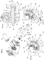
- the container 14 defines a container bottom wall 16, a container peripheral wall 18 extending therefrom and a container top aperture 20 delimited by a container top edge 19 of the container peripheral wall 18 substantially opposed to the container bottom wall 16.
- the present invention is however also usable to cover other structures that may lack the container bottom wall 16 or part of the container peripheral wall 18.
- the container top aperture 20 defines an aperture first end 24 and a substantially opposed aperture second end 26.
- the tarpaulin 12 defines a tarpaulin first end 28 and a substantially opposed tarpaulin second end 30, as seen for example in FIG. 15 .
- the tarpaulin 12 is secured to the container 14 at the tarpaulin first end 28 substantially opposed to the aperture second end 26 and is movable between tarpaulin retracted and extended configurations in which the tarpaulin 12 is respectively substantially retracted from the container top aperture and 20 extended across the container top aperture 20, as seen respectively in FIGS. 2 and 3 .
- the container 14 defines opposed container first and second ends 11 and 13 and opposed container first and second sides 15 and 17 each extending between the container first and second ends 11 and 13.
- the aperture first and second ends 24 and 26 are provided respectively at the container first and second ends 11 and 13.
- the container 14 is typically part of a vehicle or a trailer to be pulled by a vehicle.
- the container 14 is mountable on a platform truck, an open top truck trailer or the bin of a dump truck, among other possibilities.
- the device 10 is usable with other suitable containers 14. In some embodiments, the device 10 is usable to cover a railroad car.
- the aperture first and second ends 24 and 26 are not necessarily at the front or rear of the container 14, front and rear being related to the direction in which the container 14 is moved by the vehicle. As shown in the drawings, the aperture first and second ends 24 and 26 may be on edges of the container 14 that extend parallel to the direction of motion of the container 14 in typical operation.
- FIGS. 1 to 3 illustrate a case in which the container 14 is moved in a direction perpendicular to a line joining the aperture first and second ends 24 and 26.
- the tarpaulin 12 is therefore retracted laterally relative to the direction of motion. However, it is within the scope of the invention to have tarpaulins 12 retractable along the direction of motion.
- the tarpaulin 12 may be directly secured to the container 14, or may be secured thereto indirectly, for example through anchoring straps (not shown in the drawings) that extend between the tarpaulin 12, at the tarpaulin first end 28 for example, and the container 14.
- anchoring straps are secured to the container 14, for example to the container peripheral wall 18 below the aperture first end 24.
- the tarpaulin 12 is secured to the container 14 substantially opposed to the aperture second end 26 so that when extended, the tarpaulin 12 extends across the container top aperture 20. To that effect, the tarpaulin 12 may be secured to the container peripheral wall 18 below the aperture first end 24 or adjacent the aperture first end 24, among other possibilities.
- the device 10 includes a rod 32, an actuator assembly 34 and a transmission assembly 36.
- the transmission assembly 36 is provided between the rod 32 and the actuator assembly 34 and transmits rotation produced in the actuator assembly 34 to the rod 32 so that the latter can be used to extend and withdraw the tarpaulin 12.
- the rod 32 defines a rod longitudinal axis 38.
- the rod 32 is movable between rod first and second positions, seen respectively in FIGS. 2 and 3 , wherein the rod 32 is respectively substantially adjacent the aperture first and second ends 24 and 26.
- the tarpaulin 12 is mountable to the rod 32 at the tarpaulin second end 30 to allow rolling of the tarpaulin 12 thereonto and unrolling of the tarpaulin 12 therefrom when the rod 32 is rotated about the rod longitudinal axis 38.
- the tarpaulin 12 is secured to the rod 32 at the tarpaulin second end 30 in a conventional manner.
- the actuator assembly 34 includes a motor 40, a crank 42, and a driving shaft 44 defining a substantially longitudinal driving shaft rotation axis 46.
- the actuator assembly 34 also includes an actuator body 47 to which the motor 40, crank 42, and driving shaft 44 are mounted.
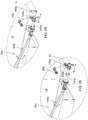
- the actuator assembly 34 is configurable between a motorized configuration and a manual configuration, seen for example respectively in FIGS. 4 and 5 .
- the motor 40 is mechanically coupled to the driving shaft 44 for selectively rotating the driving shaft 44 about the driving shaft rotation axis 46 when the motor 40 is powered.
- the motor 40 is uncoupled from the driving shaft 44 and the crank 42 is mechanically coupled to the driving shaft 44 so that the crank 42 is usable to selectively rotate the driving shaft 44 independently of the motor 40. More details regarding the structure and operation of the actuator assembly 34 are provided hereinbelow.
- the motor 40 is any suitable motor, such as for example and non-limitingly an electrical motor, an hydraulic motor or a pneumatic motor connected to a suitable power supply and to a controller (both not shown in the drawings) in a conventional manner.
- the controller allows to selectively cause the motor 40 to turn in a selected direction by suitably powering the motor 40, and to selectively remove power to the motor 40.
- the transmission assembly 36 is provided between the actuator assembly 34 and the rod 32.
- the transmission assembly 36 is operatively coupled to the actuator assembly 34 and to the rod 32 for transmitting rotations of the driving shaft 44 to the rod 32 so that rotation of the driving shaft 44 about the driving shaft rotation axis 46 causes rotation of the rod 32 about the rod longitudinal axis 38. More details regarding the structure and operation of the transmission assembly 36 are provided hereinbelow.
- Rotating the rod 32 using the actuator assembly 34 to roll the tarpaulin 12 therearound moves the rod 32 towards the rod first position to move the tarpaulin 12 to the tarpaulin retracted configuration.
- Rotating the rod 32 using the actuator assembly 34 to unroll the tarpaulin 12 therefrom moves the rod 32 towards the rod second position to move the tarpaulin 12 to the tarpaulin extended configuration.
- At least one biasing element 48 is operatively coupled to the rod 32 for biasing the rod 32 towards the rod second position.
- the tarpaulin 12 is not rigid enough to push the rod 32 towards the rod second position when the tarpaulin 12 is unrolled from the rod 32. Therefore, this movement must be caused separately, for example using the biasing element 48.
- this movement may be provided in any other suitable manner, for example passively if the tarpaulin is rigid enough, or under the action of gravity if the top aperture peripheral edge 22 is slanted.
- a motor may be used to move the rod 32 towards the rod second position. Movements of the rod 32 towards the rod first position are usually automatically achieved are rolling the tarpaulin 12 around the rod 32 reduces a distance between the rod and the aperture first end 24.
- actuator assembly 34 an exemplary embodiment of the actuator assembly 34 is now described in greater details.
- the reader skilled in the art will appreciate that different actuator assemblies are within the scope of the appended claims. Non-limiting examples of alternative actuator assemblies are described hereinbelow.
- the motor 40 is not directly coupled to the driving shaft 44.
- the actuator assembly 34 includes an intermediate shaft 52 mechanically coupled to the motor 40 so as to be rotatable thereby and a shaft coupling element 54.
- the intermediate shaft 52 defines a shaft passageway 53 extending longitudinally therethrough coaxially with the driving shaft rotation axis 46.
- the driving shaft 44 extends in the shaft passageway 53 and protrudes therefrom.
- the driving shaft 44 protrudes at both ends from the shaft passageway 53.
- the driving shaft 44 may protrude only at one end thereof from the shaft passageway 53.
- the shaft coupling element 54 is movable between coupling and uncoupling configurations, seen respectively in FIGS. 9 and 10 .
- the shaft coupling element 54 couples the intermediate shaft 52 and driving shaft 44 to each other so that the motor 40 and driving shafts 44 are jointly rotatable about the driving shaft rotation axis 46.
- the driving shaft 44 is rotatable about the driving shaft rotation axis 46 independently from the intermediate shaft 52, and therefore independently from the motor 40.
- the shaft coupling element 54 may take any suitable form.
- the shaft coupling element 54 takes the form of an element that may selectively couple the driving and intermediate shafts 44 and 52 to each other so that the intermediate shafts 44 and 52 are jointly rotatable.
- intermediate shaft 52 defines an intermediate shaft coupling portion 56 and the driving shaft 44 defines a driving shaft coupling portion 58.
- the shaft coupling element 54 secures the intermediate and driving shaft coupling portions 56 and 58 to each other in the coupling configuration. In the uncoupling configuration, the intermediate and driving shaft coupling portions 56 and 58 are free to rotate relative to each other. Typically, the intermediate and driving shaft coupling portions 56 and 58 are substantially adjacent to each other.
- the intermediate shaft 52 includes a substantially cylindrical intermediate shaft main portion 57 and the intermediate shaft coupling portion 56 extends integrally from the intermediate shaft main portion 57 at one end thereof so that the intermediate shaft main portion 57 and intermediate shaft coupling portion 56 are jointly rotatable.
- the driving shaft 44 includes a substantially cylindrical driving shaft main portion 59 and the driving shaft coupling portion 58 extends integrally from the driving shaft main portion 59 at one end thereof so that the driving shaft main portion 59 and driving shaft coupling portion 58 are jointly rotatable.
- the driving shaft main portion 59 extends through the intermediate shaft coupling and main portions 56 and 57 and the driving shaft coupling portion 58 protrudes from the intermediate shaft 52.
- the shaft coupling element 54 includes a collar 60.
- the collar 60 receives thereinto and overlaps at least part of each of the intermediate and driving shaft coupling portions 56 and 58 in the coupling configuration. In the uncoupling configuration, the collar 60 is completely removed from the intermediate and driving shaft coupling portions 56 and 58, or overlaps only one of the intermediate and driving shaft coupling portions 56 and 58.
- the collar 60 may be coupled to the intermediate and driving shaft coupling portions 56 and 58 in any suitable manner in the coupling configuration to ensure that the intermediate and driving shaft coupling portions 56 and 58 are jointly rotatable.
- the intermediate and driving shaft coupling portions 56 and 58 each have a transversal cross-sectional configuration lacking continuous rotational symmetry, such as, for example and non-limitingly, a substantially polygonal transversal cross-sectional configuration.
- the intermediate and driving shaft coupling portions 56 and 58 each have a transversal cross-sectional configuration that differs from a circle.
- the collar 60 is hollow and substantially fittingly receives the intermediate and driving shaft coupling portions 56 and 58 so that in the coupling configuration, the collar 60 is jointly rotatable about the driving shaft rotation axis 46 along with the intermediate and driving shafts 52 and 44.
- the shaft coupling element 54 is selectively lockable in the coupling configuration. However, in other embodiments, this is not the case. More specifically, for example, the shaft coupling element 54 also includes a locking pin 64. At least one of the intermediate and driving shaft coupling portions 56 and 58, the driving shaft coupling portion 58 in the embodiment shown in the drawings, defines a pin receiving aperture 66 extending laterally therethrough and the collar 60 defines a pair of collar apertures 68 extending laterally therethrough laterally opposed to each other. In the coupling configuration, the collar apertures 68 are in register with the pin receiving aperture 66 and the locking pin 64 is insertable through both the collar apertures 68 and the pin receiving aperture 66 to lock the shaft coupling element 54 in the coupling configuration. Removing the locking pin 64 from the the collar apertures 68 and the pin receiving aperture 66 then allows to slide the collar 60 relative to the intermediate and driving shaft coupling portions 56 and 58 to achieve the uncoupling configuration.
- the motor 40 is coupled to the intermediate shaft 52 in any suitable manner.
- the motor 40 includes a motor output shaft 70 and a worm gear 72 extends between the motor output shaft 70 and the intermediate shaft 52 coupling the motor 40 and the intermediate shaft 52 to each other so that the motor 40 can rotate the intermediate shaft 52.
- the worm gear 72 includes a worm 74 driven by the motor output shaft 70 and a worm wheel 76 extending radially outwardly from the intermediate shaft 52 and jointly rotatable therewith.
- the worm 74 engages the worm wheel 76.
- the worm wheel 76 is permanently engaged with the worm 74 during normal operation of the device 10, whether the actuator assembly 34 is in the motorized or manual configurations.
- the actuator body 47 is configured to securely mount thereto the motor 40, worm gear 72, intermediate shaft 52 and driving shaft 44.
- the actuator body 47 is mounted to the container 14 in any suitable manner. An example of such a suitable manner is further described hereinbelow.
- crank 42 In the manual configuration, the crank 42 is secured to the driving shaft 44, as seen in FIG. 5 . In some embodiments, not shown in the drawings, the crank 42 is permanently secured to the driving shaft 44. However, in other embodiments, as illustrated in the drawings, the crank 42 is removably mountable to the remainder of the actuator assembly 34.
- the crank 42 includes a crank attachment portion 78, a crank handle 80 and a crank spacing portion 82 extending therebetween.
- the crank attachment portion 78 is mountable to a protruding portion of the driving shaft 44 that protrudes from the intermediate shaft 52 opposite to the transmission assembly 36.
- the crank attachment portion 78 is removably mountable to the driving shaft coupling portion 58 when the collar 60 is withdrawn therefrom.
- the crank attachment portion 78 defines a crank aperture 84 substantially snugly receiving the driving shaft coupling portion 58.
- the device 10 defines a crank receiving element 86, for example a collar opening substantially vertically, for receiving the crank 42 thereinto when the crank 42 is detached from the driving shaft 44.
- the crank receiving element is configured to that the crank attachment portion 78 and crank spacing portion 82 can be received therethrough, but so as to prevent the crank handle 80 from passing therethrough. Therefore, the crank 42 can be safely stowed when not in use.
- the transmission assembly 36 transmits the rotation of the driving shaft 44 to the rod 32.
- the actuator assembly 34 is provided close to the container bottom wall 16 so as to be relatively easily operable in the manual configuration.
- the transmission assembly 36 must therefore transmit this rotation of the driving shaft 44 up to the rod 32, which is provided adjacent the container top aperture 20.
- the transmission assembly 36 is configured and sized so that a distance between the driving shaft 44 and the rod 32 remains substantially constant as the rod 32 moves between the rod first and second positions. This may require in some embodiments that the actuator assembly 34 be mounted so as to be movable relative to the container 10.
- the transmission assembly includes an elongated arm 90 defining an arm longitudinal axis 92.
- the arm 90 defines substantially opposed arm first and second ends 94 and 96, seen for example respectively in FIGS. 4 and 13 .
- the arm first end 94 is substantially adjacent to the driving shaft 44.
- the arm second end 96 is substantially adjacent to the rod 32.
- the arm 90 is operatively coupled to the driving shaft 44 and rod 32 so that rotation of the driving shaft 44 about the driving shaft rotation axis (not shown in FIG.
- the arm 90 causes rotation of the arm 90 about the arm longitudinal axis 92, which in turn causes rotation of the rod 32 about the rod longitudinal axis 38.
- the arm 90 extends substantially perpendicular to the rod 32 and is pivotable relative to the driving shaft 44 between arm first and second positions, shown respectively in FIGS. 2 and 3 , wherein the rod 32 is respectively in the rod first and second positions.
- the arm 90 is a fixed length arm so that a distance between the driving shaft 44 and the rod 32 is fixed.
- the arm 90 may be a telescopic arm having a variable length.
- the actuator assembly 34 may be fixed relative to the container 14.
- the transmission assembly 36 also includes gearboxes and other components that allow pivotal movements of the arm 90 and allow transmission of the rotation of the driving shaft 44 to the rod 32.
- the driving shaft 44 is substantially horizontal and the transmission assembly includes a first 90 degrees gearbox 100 between the arm 90 and the driving shaft 44 and a second 90 degrees gearbox 102 between the arm 90 and the rod 32.
- the arm 32 is coupled to the first 90 degrees gearbox 100 using a universal joint 104 to allow pivotal movement of the arm 90 between the arm first and second positions as the rod 32 moves between the rod first and second positions.
- the path of the rod 32 between the rod first and second positions differs from an arc segment centered on the universal joint 104 with a radius of curvature equal to the length of the arm 90. Therefore, the arm 90 needs to be telescopic, or the location about which the arm 90 pivots needs to move relative to the container 14. This last option is illustrated in the drawings.
- the device 10 includes a mounting bracket 106 secured to the transmission assembly 34 for mounting the transmission assembly 36 to the container peripheral wall 18.
- the mounting bracket 106 is configured and sized for allowing vertical movements the arm 90 relative to the container peripheral wall 18. This is achieved by suitably mounting part of the transmission assembly 36 thereto.
- the actuator assembly 34 is also mounted to the mounting bracket 106.
- the mounting bracket 106 includes a base 108 fixedly secured to the container peripheral wall 18 (not shown in FIG. 7 , and a bracket mobile portion 110 movable vertically relative to the container 14.
- the arm 90 is mechanically coupled to the bracket mobile portion 110 at the arm first end 94 so that the arm first end 94 is vertically movable along with the bracket mobile portion 110, for example through the first 90 degrees gearbox 100.
- the mounting bracket 106 also includes a pair of levers 112 extending substantially parallel to each other and vertically spaced apart from each other.
- two pairs of levers 112 are provided.
- the two pairs of levers 112 are substantially parallel to each other and spaced apart from each other in a direction leading between the container first and second ends 11 and 13 .
- Each lever 112 is pivotally mounted at one end 114 thereof to the base 108 and pivotally mounted at another end 116 thereof to the bracket mobile portion 110.
- the bracket mobile portion 110 takes for example the form of a frame to which other components may be secured.
- the actuator assembly 34 is mounted to the bracket mobile portion 110, along with part of the transmission assembly 36. More generally, one of the actuator and transmission assemblies 34 and 36 is mounted to the bracket mobile portion 110.
- the first 90 degrees gearbox 100 is mounted to the bracket mobile portion so as to be rotated by the actuator assembly 34.
- the base 108 is mounted to the container 14 on the container first side 15, for example substantially adjacent the container bottom wall 16 and substantially midway between the container first and second ends 11 and 13.
- any suitable container 14 may be used with the device 10.
- the tarpaulin 12 is supported by the container 14 when moving between the tarpaulin first and second positions.
- the container 14 defines at least one tarpaulin support 118 extending between the container first and second ends 11 and 13 across the container top aperture 20.
- the at least one tarpaulin support includes at least two arches 120 spaced apart from each other and each extending across the container top aperture 20 between the container first and second ends 11 and 13.
- three arches 120 are provided, one adjacent each of the container first and second sides 15 and 17, and a third one midway between the first two ones.
- any other suitable number of arches 120 is usable.
- Each arch 120 includes for example three rectilinear tubes joined sequentially to each other.
- the at least one tarpaulin support includes part of the top aperture peripheral edge 22 on which the rod 32 and/or tarpaulin 12 are supported.
- a support rod 122 is mounted to the tarpaulin 12 at a location intermediate the tarpaulin first and second ends 28 and 30.
- the support rod 122 is provided so that when the tarpaulin 12 is in the extended configuration, the support rod 122 is midway between the aperture first and second ends 24 and 26 and extends along substantially the distance between the container first and second sides 15 and 17.
- the support rod 122 is rolled around the rod 32 along with the tarpaulin 12 when the latter is sufficiently rolled around the rod 32.
- anchoring blocks 123 are provided.
- the device 10 may include a plurality of anchoring blocks 123 spaced apart from each other along the container top aperture 20 substantially adjacent the aperture second end 26.
- the anchoring blocks 123 are provided slightly below the aperture second end 26 and each define a recess 125, for example an inverted J-shaped recess 125.
- the recess 125 opens generally towards a plane containing the container bottom wall 16 when the anchoring blocks 123 are operatively mounted to the container 14 and the recess 125 is configured and sized for receiving the rod 32 thereinto when arm 90 is in the arm second position.
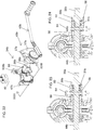
- FIGS. 11 to 13 illustrate respectively various biasing element 48b, 48 and 48a usable in the device 10.
- the device 10 typically includes two of these biasing elements 48, 48a and 48b, one provided at each end of the rod 32, but use of one or more than two biasing elements 48, 48a and 48b is within scope of the invention.
- all the biasing elements 48, 48a and 48b may be of the same type, or various types may be mixed in the same device 10. All the types of biasing elements 48, 48a and 48b are provided to pull the rod 32 towards the rod second position.
- the biasing element 48 includes a coil spring 124 mounted in a tubular body 126 fixed to the container 14. One end of the coil spring 124 is fixed relative tubular body 126 (not shown in the drawings), and a cable 128 extends from the other end of the coil spring 124.
- the cable 128 is rolled around the rod 32 so that it unrolls therefrom when the rod 32 is moved towards the rod first position and is rolled therearound when the rod 32 is moved towards the rod second position.
- a tension is present in the coil spring 124 so that the cable 128 pulls on the rod 32 towards the rod second position.
- the biasing element 48a includes a pulley 130 mounted rod 32 so as to be rotatable relative thereto.
- a torsion spring 132 extends between the pulley 130 and the rod 32.
- a cable 134 is rolled around the pulley 130 at one end thereof and is secured to the container 14 at the container second end 13 at the other end thereof.
- the torsion spring 132 is configured to exert a torque pulling on the cable 134 so that the cable 134 has a tendency to be rolled around the pulley 130, which biases the rod 32 towards the rod second position.
- the biasing element 48b includes a coil spring 136 mounted in the rod 32, which is hollow along at least part thereof.
- One end of the coil spring 136 is fixed longitudinally relative rod 32 (not shown in the drawings), and a cable 138 extends from the other end of the coil spring 136.
- the cable 138 protrudes from the rod 32 and is fixed to the container 14 at the container second end 13.
- a tension is present in the coil spring 136 so that the cable 138 pulls on the rod 32 towards the rod second position.
- Biasing elements similar to the biasing elements 48, 48a and 48b, and usable in the device 10 are further described in US Patents 6,595,594 issued July 22, 2003 and 7,506,912 issued March 24, 2009 , both issued to Royer, and US Patent Application Publication 20020021018 of Royer published February 21, 2002 .
- the device 10 works as follows. Taking for example as an initial configuration the configuration shown in FIG. 2 with the actuator assembly 34 in the motorized configuration, the arm 90 is in the arm first position. The rod 32 is thus in the rod first position with the tarpaulin 12 rolled therearound. The biasing element 48 biases the rod 32 towards the rod second position.
- the structure of the motor 40 and of the components linking the motor 40 to the rod 32 prevents the rod 32 from moving. It should be noted that in alternative embodiments other components, such as a lock, a clutch or a brake, prevent this movement instead.
- the intermediate shaft 52 is rotated through the worm gear 72. Since the shaft coupling element 54 is in the coupling configuration, the driving shaft 44 is then also rotated by the action of the motor 40, which turns the various elements of the transmission assembly 36 to rotate the rod 32 so that the tarpaulin 12 is released from the rod 32. The rod 32 is then free to move under the action of the biasing element 48 until the extended configuration is achieved.
- the bracket mobile portion 110 moves up and down due to the pivotal movement of the levers 112 as the tarpaulin moves between the tarpaulin retracted and extended configurations to endure that the rod 32 is always supported by the container 14. Retraction of the tarpaulin 12 is achieved by rotating the motor 40 in the opposite direction.
- the actuator assembly 34 is moved to the manual configuration by sliding the collar 60 so that the driving shaft 44 is free to rotate relative to the intermediate shaft 52. Then, the crank 42 is mounted to the driving shaft 44 and can be used to rotate the rod 32 in either direction.
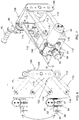
- FIGS. 16 to 18 illustrate an alternative actuator assembly 34a similar to the actuator assembly 34.
- the actuator assembly 34a is similar in structure and function to the actuator assembly 34 except that the driving shaft 44a is vertical and only needs to protrude from the intermediate shaft 52a at one end thereof. Since the driving shaft 44a is vertical, the first 90 degrees gearbox 100 can be omitted and the driving shaft 44a can be directly coupled to the universal joint 104.
- the driving shaft 44a is provided with a driving shaft gear 45a extending circumferentially therearound outside of the intermediate shaft 52, for example further away from the intermediate shaft coupling portion 56 than the driving shaft coupling portion 58.
- the crank 42 is part of a crank assembly 43a including a crank gear 39a and a crank assembly body 37a.
- the crank 42 is operatively coupled to the crank gear 39a for selectively rotating the crank gear 39a relative to the crank assembly body 37a.
- the crank assembly body 37a is mountable to a remainder of the actuator assembly 34a so that the crank 42 and driving shaft gears 45a are engaged with each other, for example perpendicular to each other, so that rotating the crank 42 is may rotate the driving shaft 44a.
- the crank assembly 43a includes a crank assembly shaft 35a rotatably mounted in a suitably located and configured mounting aperture 33a extending through the crank assembly body 37a.
- the crank assembly shaft 35a protrudes at both ends thereof from the crank assembly body 37a.
- the crank 42 and crank gear 39a are mounted at respective ends of the crank assembly shaft 35a so that the crank 42, crank assembly shaft 35a and crank gear 39a are jointly rotatable.
- the crank assembly body 37a is typically removably mountable to the remainder of the actuator assembly 34a so that when operatively mounted thereto, the crank gear 39a engages the driving shaft gear 45a so that rotating the crank gear 39a rotates the driving shaft gear 45a.
- the crank assembly body 37a defines a pair of opposed tongues 31a each slidably receivable in a respective substantially horizontal slit 29a when the crank assembly 44a is operatively mounted to the remainder of the actuator assembly 34a.
- the crank 42 can be rotated to rotate the driving shaft 44a, as in the embodiment of the actuator assembly 34 described hereinabove.
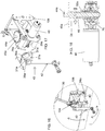
- FIGS. 21 to 24 illustrate an alternative actuator assembly 34b and an alternative transmission assembly 36b.
- the actuator assembly 34b is provided at one of the container first and second ends 11 and 13, to facilitate access to the crank 42b by an intended user. More specifically, instead of being mounted directly to the mounting bracket 106, the actuator assembly 34b is mounted to the container 14 substantially adjacent to one of the container first and second ends 11 and 13 (the container second end 13 in the specific example illustrated in the drawings).
- the transmission assembly 36b includes an intermediate gearbox 100b, replacing the first 90 degrees gearbox 100 and an extension shaft 140b.
- the extension shaft 140b extends between the driving shaft 44b and the intermediate gearbox 100b.
- the intermediate gearbox 100b is mounted to the bracket mobile portion 110, and the arm 90 is mounted to the intermediate gearbox 100b similarly to the manner in which the arm 90 is mounted to the first 90 degrees gearbox 100.
- the intermediate gearbox 100b is for example a 90 degrees gearbox.
- the actuator assembly 34b, extension shaft 140b, intermediate gearbox 100b and arm 90 are mechanically coupled to each other so that rotation of the driving shaft 44b about the driving shaft rotation axis 46 causes rotation of the arm 90 about the arm longitudinal axis 92.
- the extension shaft 140b is telescopic and is coupled to the driving shaft 44a and intermediate gearbox 100b with universal joints to accommodate vertical movements of the bracket mobile portion 110.
- FIG. 22 better illustrate the actuator assembly 34b.
- the actuator body 47b is provided with an actuator body mounting bracket 150b securable to the container 14 (not shown in FIG. 22 ).
- the crank 42b is part of a crank assembly 43b including a crank assembly shaft 35b rotatably mounted in a suitably located and configured mounting aperture (not shown in the drawings) extending through a crank assembly body 37b mountable to the container 14.
- the crank assembly shaft 35b may be mounted to the crank assembly body 37b using a bearing to facilitate its rotation.
- the actuator assembly 34b has any other suitable configuration and is mounted to the container 14 in any other suitable manner.
- crank assembly shaft 35b protrudes at both ends thereof from the crank assembly body 37b.
- the crank assembly shaft 35b may extend integrally from the driving shaft 44b, or, as shown in FIGS. 23 and 24 , may be coupled thereto axially through a bearing 31b opposed to the crank 42b (not shown in FIGS. 23 and 24 ).
- the bearing 31b allows the crank assembly shaft 35b and the driving shaft 44b to rotate freely relative to each other.
- the collar 60 is moved to overlap a crank shaft coupling portion 29b similar in cross-section to the driving shaft coupling portion 58, thereby allowing locked joint rotation of the crank assembly shaft 35b and driving shaft 44b.
- Motorized and manual configurations are illustrated in FIGS. 23 and 24 respectively.
- crank 42 When the bearing 31b is used, the crank 42 may be permanently left secured to the crank assembly shaft 35b as in motorized operation, the collar 60 is withdrawn from the crank shaft coupling portion 29b and rotation of the driving shaft 44b does not cause rotation of the crank assembly shaft 35b.
- the crank assembly 43b is provided with a conventional ratchet type mechanism 27b.
- the ratchet type mechanism 27b is configurable to prevent rotation of the crank 42b in an undesired direction, while allowing rotation of the crank 42b in the opposite direction.
- FIG. 20 illustrates yet another actuator and transmission assemblies 34c and 36c configuration.
- the actuator and transmission assemblies 34c and 36c are similar to the actuator and transmission assemblies 34b and 36b except that the extension shaft 140c is provided between the driving shaft 44c and the crank assembly shaft 35b, and is therefore part of the actuator assembly 34c instead of being part of the transmission assembly 36c.
- the driving shaft 44c is therefore directly attached to the intermediate gearbox 100c. Otherwise, the actuator and transmission assemblies 34c and 36c and the actuator and transmission assemblies 34b and 36b operate similarly and have similar structures.
- the motor 40, worm gear 72 and intermediate shaft 52 are omitted and that in these embodiments, the actuator assembly 34, 34a or 34b is completely manually operated.
- the actuator assembly may be similar to the actuator assembly 34, except for the absence of the components required for motorized operation.
- the actuator assembly 34d and transmission assembly 36d may be as illustrated in FIG. 19 , which is similar to the actuator assembly 34c and transmission assembly 36c, except that the the motor 40, worm gear 72 and intermediate shaft 52 are omitted.
- the extension shaft 104d is therefore coupled to the intermediate gearbox 100d for joint rotation therewith.
- an actuator assembly 34e is similar to the actuator assembly 34d except that the actuator assembly 34e includes a crank extension shaft 141e supporting the crank 42e.
- the crank extension shaft 141e is telescopic so as to be configurable between a retracted configuration (seen in FIG. 25 ) and an extended configuration (seen in FIG. 26 ).
- the crank 42e is retracted from the container second end 33 so that the crank 42e is not exposed when not needed.
- the crank 32e protrudes from the container second end 33 so that the crank 42e can be operated as described hereinabove.
- a crank securing member 143e is provided adjacent the crank 42e and engages a suitably shaped container securing member 145e to stabilize the crank 42e in the extended configuration.
Landscapes
- Engineering & Computer Science (AREA)
- Mechanical Engineering (AREA)
- Transmission Devices (AREA)
- Load-Engaging Elements For Cranes (AREA)
- Tents Or Canopies (AREA)
- Power-Operated Mechanisms For Wings (AREA)
- Auxiliary Devices For And Details Of Packaging Control (AREA)
Claims (14)
- Vorrichtung (10) zum Handhaben einer Plane (12), um zumindest einen Teil eines Containers (14) mit der Plane (12) abzudecken, wobei der Container (14) eine Containerbodenwand (16), eine sich davon erstreckende Containerumfangswand (18) und eine obere Containeröffnung (20) definiert, die durch eine Containeroberkante (19) der Containerumfangswand (18) gegenüber der Containerbodenwand (16) begrenzt ist, wobei die obere Containeröffnung (20) ein erstes Öffnungsende (24) und ein gegenüberliegendes zweites Öffnungsende (26) definiert, wobei die Plane (12) ein erstes Planenende (28) und ein gegenüberliegendes zweites Planenende (30) definiert, wobei die Plane (12) am ersten Planenende (28), das dem zweiten Öffnungsende (26) gegenüberliegt, am Container (14) befestigt und zwischen einer eingezogenen und einer ausgezogenen Planenkonfiguration bewegbar ist, in denen die Plane (12) jeweils von der oberen Containeröffnung (20) eingezogen und über die obere Containeröffnung (20) ausgezogen ist, wobei die Vorrichtung (10) Folgendes umfasst:- eine Stange (32), die eine Stangenlängsachse (38) definiert, wobei die Stange (32) zwischen einer ersten und einer zweiten Stangenposition beweglich ist, wobei die Stange (32) jeweils neben dem ersten und zweiten Ende (24 und 26) der Öffnung liegt, wobei die Plane (12) an der Stange (32) am zweiten Planenende befestigt werden kann, um das Aufrollen der Plane (12) darauf und das Abrollen der Plane (12) davon zu ermöglichen, wenn die Stange (32) um die Stangenlängsachse (38) gedreht wird;- eine Stellantriebsanordnung (34), wobei die Stellantriebsanordnung (34) einen Motor (40) mit einer Motorabtriebswelle (70), einer Kurbel (42) und einer eine longitudinale Antriebswellendrehachse (46) definierenden Antriebswelle (44) aufweist, wobei die Stellantriebsanordnung (34) zwischen einer motorisierten Konfiguration und einer manuellen Konfiguration konfigurierbar ist, wobei in der motorisierten Konfiguration der Motor (40) mechanisch mit der Antriebswelle (44) gekoppelt ist, um die Antriebswelle (44) selektiv um die Antriebswellendrehachse (46) zu drehen, wenn der Motor (40) mit Strom versorgt wird, und in der manuellen Konfiguration der Motor (40) von der Antriebswelle (44) abgekoppelt ist und die Kurbel (42) mechanisch mit der Antriebswelle (44) gekoppelt ist, so dass die Kurbel (42) benutzt werden kann, um die Antriebswelle (44) unabhängig vom Motor (40) selektiv zu drehen; und- eine Getriebeanordnung (36) zwischen der Stellantriebsanordnung (34) und der Stange (32), wobei die Getriebeanordnung (36) operativ mit der Stellantriebsanordnung (34) und der Stange (32) gekoppelt ist, um Drehungen der Antriebswelle (44) auf die Stange (32) zu übertragen, so dass eine Drehung der Antriebswelle (44) um die Antriebswellendrehachse (46) eine Drehung der Stange (32) um die Stangenlängsachse (38) bewirkt; wobei das Drehen der Stange (32) mit Hilfe der Stellantriebsanordnung (34), um die Plane (12) darum zu rollen, die Stange (32) in Richtung der ersten Position der Stange bewegt, um die Plane (12) in die eingezogene Konfiguration der Plane zu bewegen, und das Drehen der Stange (32) mit Hilfe der Stellantriebsanordnung (34), um die Plane (12) davon abzurollen, die Stange (32) in Richtung der zweiten Position der Stange bewegt, um die Plane (12) in die ausgezogene Konfiguration der Plane zu bewegen; dadurch gekennzeichnet, dass die Stellantriebsanordnung (34) eine Zwischenwelle (52) aufweist, die mechanisch mit der Motorabtriebswelle (70) gekoppelt ist, so dass sie davon gedreht werden kann, wobei die Zwischenwelle (52) einen Wellendurchgang (53) definiert, der sich longitudinal durch sie hindurch koaxial mit der Antriebswellendrehachse (46) erstreckt, wobei sich die Antriebswelle (44) im Wellendurchgang (53) erstreckt und davon vorsteht, wobei die Stellantriebsanordnung (34) ferner ein Wellenkopplungselement (54) aufweist, das zwischen einer Kopplungs- und einer Entkopplungskonfiguration bewegt werden kann, wobei in der Kopplungskonfiguration das Wellenkopplungselement (54) die Zwischenwelle (52) und die Antriebswelle (44) miteinander koppelt, so dass die Motorabtriebswelle (70) und die Antriebswelle (44) gemeinsam gedreht werden können, um die Antriebswelle (44) um die Antriebswellendrehachse (46) zu drehen, und in der Entkopplungskonfiguration die Antriebswelle (44) unabhängig von der Zwischenwelle (52) um die Antriebswellendrehachse (46) gedreht werden kann.
- Vorrichtung (10) nach Anspruch 1, die ferner ein Vorspannelement (48) umfasst, das operativ mit der Stange (32) gekoppelt ist, um die Stange (32) in Richtung der zweiten Stangenposition vorzuspannen.
- Vorrichtung (10) nach Anspruch 1, wobei die Zwischenwelle (52) einen Zwischenwellenkupplungsabschnitt (56) definiert und die Antriebswelle (44) einen Antriebswellenkupplungsabschnitt (58) definiert, wobei das Wellenkupplungselement (54) den Zwischen- und den Antriebswellenkupplungsabschnitt (56 und 58) in der Kupplungskonfiguration aneinander befestigt, wobei der Zwischen- und der Antriebswellenkupplungsabschnitt (56 und 58) nebeneinander liegen, wobei das Wellenkupplungselement (54) einen Kragen (60) aufweist, wobei der Kragen (60) in der Verriegelungskonfiguration zumindest einen Teil jedes der Zwischen- und Antriebswellenkupplungsabschnitte (56 und 58) aufnimmt und damit überlappt, wobei der Zwischen- und der Antriebswellenkupplungsabschnitt (56 und 58) jeweils eine transversale Querschnittskonfiguration ohne kontinuierliche Rotationssymmetrie aufweisen, wobei der Kragen (60) den Zwischen- und den Antriebswellenkupplungsabschnitt (56 und 58) passend aufnimmt, so dass der Kragen (60) in der Verriegelungskonfiguration zusammen mit der Zwischen- und der Antriebswelle (52 und 44) um die Antriebswellendrehachse (46) gedreht werden kann, wobei optional der Zwischen- und der Antriebswellenkupplungsabschnitt (56 und 58) jeweils eine polygonale transversale Querschnittskonfiguration haben.
- Vorrichtung (10) nach Anspruch 3, wobei das Wellenkupplungselement (54) selektiv in der Kupplungskonfiguration verriegelbar ist, wobei optional das Wellenkupplungselement (54) auch einen Verriegelungsstift (64) aufweist, wobei der Antriebswellenkupplungsabschnitt (58) eine Stiftaufnahmeöffnung (66) definiert, die sich lateral durch ihn hindurch erstreckt, wobei der Kragen (60) ein Paar Kragenöffnungen (68) definiert, die sich lateral durch ihn hindurch erstrecken und einander lateral gegenüberliegen, wobei in der Kupplungskonfiguration die Kragenöffnungen (68) mit der Stiftaufnahmeöffnung (66) ausgerichtet sind und der Verriegelungsstift (64) sowohl durch die Kragenöffnungen (68) als auch durch die Stiftaufnahmeöffnung (66) eingeführt werden kann, um das Wellenkupplungselement (54) in der Kupplungskonfiguration zu verriegeln.
- Vorrichtung (10) nach einem der Ansprüche 1 bis 4, wobei die Antriebswelle (44a) mit einem Antriebswellengetriebe (45a) versehen ist, das sich in Umfangsrichtung darum herum erstreckt, wobei die Kurbel (42) Teil einer Kurbelanordnung (43a) ist, die ein Kurbelgetriebe (39a) und einen Kurbelanordnungskörper (37a) umfasst, wobei die Kurbel (42) operativ mit dem Kurbelgetriebe (39a) gekoppelt ist, um das Kurbelgetriebe (39a) relativ zum Kurbelanordnungskörper (37a) selektiv zu drehen, wobei der Kurbelanordnungskörper (37a) an einem Rest der Stellantriebsanordnung (34a) montiert werden kann, so dass Kurbel- und Antriebswellengetriebe (39a und 45a) miteinander in Eingriff stehen, so dass eine Drehung der Kurbel (42) eine Drehung der Antriebswelle (44a) bewirkt.
- Vorrichtung (10) nach einem der Ansprüche 2 bis 5, wobei die Getriebeanordnung (36) so konfiguriert und bemessen ist, dass ein Abstand zwischen der Antriebswelle (44) und der Stange (32) konstant bleibt, während sich die Stange (32) zwischen der ersten und der zweiten Stangenposition bewegt.
- Vorrichtung (10) nach einem der Ansprüche 2 bis 6, die ferner eine an der Stellantriebs- und der Getriebeanordnung (34 und 36) befestigte Montagehalterung (106) zum Montieren der Stellantriebs- und Getriebeanordnung (34 und 36) an der Containerumfangswand (18) umfasst, wobei die Montagehalterung (106) so konfiguriert und bemessen ist, dass sie vertikale Bewegungen der Stellantriebs- und Getriebeanordnung (34 und 36) relativ zur Containerumfangswand (18) ermöglicht, wenn die Montagehalterung an der Containerumfangswand befestigt ist, wobei optional die Montagehalterung (106) eine Basis (108), die fest an der Containerumfangswand (18) befestigt werden kann, und ein Paar Hebel (112) umfasst, die sich parallel zueinander und vertikal voneinander beabstandet erstrecken, wobei jeder Hebel (112) an einem Ende schwenkbar an der Basis (108) und am anderen Ende schwenkbar an der Aktuator-oder der Getriebeanordnung (34 und 36) montiert ist.
- Vorrichtung (10) nach Anspruch 7, wobei die Getriebeanordnung (36) einen länglichen Arm (90) aufweist, der eine Armlängsachse (92) definiert, wobei der Arm (90) ein erstes und ein gegenüberliegendes zweites Armende (94 und 96) definiert, wobei das erste Armende (94) neben der Antriebswelle (44) liegt und das zweite Armende (96) neben der Stange (32) liegt, wobei der Arm (90) operativ mit der Antriebswelle (44) und der Stange (32) gekoppelt ist, so dass eine Drehung der Antriebswelle (44) um die Antriebswellendrehachse (46) eine Drehung des Arms (90) um die Armlängsachse (92) bewirkt, die wiederum eine Drehung der Stange (32) um die Stangenlängsachse (38) bewirkt, wobei sich der Arm (90) lotrecht zur Stange (32) erstreckt und relativ zur Antriebswelle (44) zwischen einer ersten und einer zweiten Armposition schwenkbar ist, wobei die Stange (32) jeweils in der ersten und zweiten Stangenposition ist, wobei der Arm (90) optional ein Arm mit fester Länge ist, wobei ferner optional die Getriebeanordnung (36) ein erstes 90-Grad-Getriebe (100) zwischen dem Arm (90) und der Antriebswelle (44) und ein zweites 90-Grad-Getriebe (102) zwischen dem Arm (90) und der Stange (32) aufweist, wobei der Arm (90) mit dem ersten 90-Grad-Getriebe (100) mittels eines Universalgelenks (104) gekoppelt ist, um eine Schwenkbewegung des Arms (90) zwischen der ersten und zweiten Armposition zuzulassen, während sich die Stange (32) zwischen der ersten und zweiten Stangenposition bewegt.
- Abgedeckter Fahrzeugcontainer, der Folgendes umfasst:- einen Container (14), der eine Containerbodenwand (16), eine obere Containeröffnung (20) über der Containerbodenwand (16), ein erstes und ein gegenüberliegendes zweites Containerende (11 und 13) und eine erste und eine gegenüberliegende zweite Containerseite (15 und 17) definiert, die sich jeweils zwischen dem ersten und zweiten Containerende (11 und 13) erstrecken, wobei der Container (14) mindestens eine Planenauflage (118) definiert, die sich zwischen dem ersten und zweiten Containerende (11 und 13) über die obere Containeröffnung (20) erstreckt;- eine Plane (12), die ein erstes und ein gegenüberliegendes zweites Planenende (28 und 30) definiert, wobei die Plane (12) am ersten Containerende (11) neben dem ersten Planenende (28) befestigt ist, wobei die Plane (12) zwischen einer eingezogenen und einer ausgezogenen Konfiguration der Plane bewegbar ist, in der die Plane (12) jeweils von der oberen Containeröffnung (20) eingezogen und über die obere Containeröffnung (20) ausgezogen ist; und- eine Vorrichtung (10) zur Handhabung der Plane nach einem der Ansprüche 1 bis 8.
- Abgedeckter Fahrzeugcontainer nach Anspruch 9, wobei die Getriebeanordnung (36) einen länglichen Arm (90) aufweist, der eine Armlängsachse (92) definiert, wobei der Arm (90) ein erstes und ein gegenüberliegendes zweites Ende (94 und 96) des Arms definiert, wobei das erste Armende (94) neben der Antriebswelle (44) liegt und das zweite Armende (96) neben der Stange (32) liegt, wobei der Arm (90) operativ mit der Antriebswelle (44) und der Stange (32) gekoppelt ist, so dass eine Drehung der Antriebswelle (44) um die Antriebswellendrehachse (46) eine Drehung des Arms (90) um die Armlängsachse (92) bewirkt, die wiederum eine Drehung der Stange (32) um die Stangenlängsachse (38) bewirkt, wobei sich der Arm (90) lotrecht zur Stange (32) erstreckt und relativ zur Antriebswelle (44) zwischen einer ersten und einer zweiten Armposition schwenkbar ist, wobei die Stange (32) jeweils in der ersten und zweiten Stangenposition ist, ferner umfassend eine Montagehalterung (106), wobei die Montagehalterung (106) eine Basis (108), die fest am Container (14) montiert ist, und einen beweglichen Halterungsabschnitt (110) umfasst, der vertikal relativ zum Container (14) beweglich ist, wobei der Arm (90) mechanisch mit dem beweglichen Halterungsabschnitt (110) am ersten Armende (94) gekoppelt ist, so dass das erste Armende (94) vertikal zusammen mit dem beweglichen Halterungsabschnitt (110) beweglich ist, wobei die Montagehalterung (106) ein Paar Hebel (112) aufweist, die sich parallel zueinander und vertikal voneinander beabstandet erstrecken, wobei jeder Hebel (112) an einem Ende schwenkbar an der Basis (108) und am anderen Ende schwenkbar am beweglichen Halterungsabschnitt (110) angebracht ist, und wobei die Stellantriebsanordnung (36) am beweglichen Halterungsabschnitt (110) angebracht ist.
- Abgedeckter Fahrzeugcontainer nach Anspruch 10, wobei die Basis (108) am Container (14) auf der ersten Containerseite (17) in der Mitte zwischen dem ersten und zweiten Containerende (11 und 13) befestigt ist.
- Abgedeckter Fahrzeugcontainer nach Anspruch 10, wobei die Basis (108) am Container (14) auf der ersten Containerseite (17) montiert ist und wobei die Stellantriebsanordnung (34) am Container (14) neben dem ersten oder zweiten Containerende (11 und 13) montiert ist, wobei die Getriebeanordnung (36) ein Zwischengetriebe (100b) und eine Verlängerungswelle (140b) umfasst, wobei sich die Verlängerungswelle (140b) zwischen der Antriebswelle (44b) und dem Zwischengetriebe (100b) erstreckt, wobei das Zwischengetriebe (100b) am beweglichen Halterungsabschnitt (110) angebracht ist und der Arm (90) am Zwischengetriebe (100b) angebracht ist, wobei die Stellantriebsanordnung (34), die Verlängerungswelle (140b), das Zwischengetriebe (100b) und der Arm (90) mechanisch miteinander gekoppelt sind, so dass eine Drehung der Antriebswelle (44b) um die Wellenlängsachse (46) eine Drehung des Arms (90) um die Armlängsachse (92) bewirkt.
- Abgedeckter Fahrzeugcontainer nach Anspruch 12, wobei die Stellantriebsanordnung (34b) eine Kurbelanordnung (43b) umfasst, wobei die Kurbelanordnung (43b) die Kurbel (42b) und eine Kurbelanordnungswelle (35b) umfasst, die von der Kurbel (42b) axial gedreht werden kann, wobei die Kurbelanordnungswelle (35b) mit der Antriebswelle (44b) axial durch ein der Kurbel (42b) gegenüberliegendes Lager (31b) gekoppelt ist, wobei das Lager (31b) es zulässt, dass sich die Kurbelanordnungswelle (35b) und die Antriebswelle (44b) frei relativ zueinander drehen, wobei die Stellantriebsanordnung (34b) einen Kragen (60) aufweist, der selektiv beweglich ist, so dass er sowohl die Kurbelanordnungswelle (35b) als auch die Antriebswelle (44b) gemeinsam überlappt, wobei der Kragen (60), die Kurbelanordnungswelle (35b) und die Antriebswelle (44b) so konfiguriert und bemessen sind, dass, wenn der Kragen (60) die Kurbelanordnungswelle (35b) und die Antriebswelle (44b) überlappt, die Kurbelanordnungswelle (35b) und die Antriebswelle (44b) gemeinsam drehbar sind.
- Abgedeckter Fahrzeugcontainer nach einem der Ansprüche 9 bis 13, der ferner eine Stützstange (122) umfasst, die so an der Plane (12) montiert ist, dass sie sich an einer Stelle zwischen dem ersten und dem zweiten Planenende (28 und 30) lateral darüber erstreckt, wobei die mindestens eine Planenauflage (118) mindestens zwei Bögen (120) aufweist, die voneinander beabstandet sind und sich jeweils über die obere Containeröffnung (20) zwischen dem ersten und dem zweiten Containerende (11 und 13) erstrecken.
Priority Applications (1)
| Application Number | Priority Date | Filing Date | Title |
|---|---|---|---|
| EP21152976.3A EP3831628B1 (de) | 2018-03-01 | 2019-02-27 | Planenrückzieh- und -erweiterungsvorrichtung |
Applications Claiming Priority (1)
| Application Number | Priority Date | Filing Date | Title |
|---|---|---|---|
| CA2996958A CA2996958C (en) | 2018-03-01 | 2018-03-01 | TARPAULIN RETRACTION AND DEPLOYMENT DEVICE |
Related Child Applications (2)
| Application Number | Title | Priority Date | Filing Date |
|---|---|---|---|
| EP21152976.3A Division EP3831628B1 (de) | 2018-03-01 | 2019-02-27 | Planenrückzieh- und -erweiterungsvorrichtung |
| EP21152976.3A Division-Into EP3831628B1 (de) | 2018-03-01 | 2019-02-27 | Planenrückzieh- und -erweiterungsvorrichtung |
Publications (2)
| Publication Number | Publication Date |
|---|---|
| EP3533643A1 EP3533643A1 (de) | 2019-09-04 |
| EP3533643B1 true EP3533643B1 (de) | 2021-07-14 |
Family
ID=65628679
Family Applications (2)
| Application Number | Title | Priority Date | Filing Date |
|---|---|---|---|
| EP19159728.5A Active EP3533643B1 (de) | 2018-03-01 | 2019-02-27 | Planenrückzieh- und -erweiterungsvorrichtung |
| EP21152976.3A Active EP3831628B1 (de) | 2018-03-01 | 2019-02-27 | Planenrückzieh- und -erweiterungsvorrichtung |
Family Applications After (1)
| Application Number | Title | Priority Date | Filing Date |
|---|---|---|---|
| EP21152976.3A Active EP3831628B1 (de) | 2018-03-01 | 2019-02-27 | Planenrückzieh- und -erweiterungsvorrichtung |
Country Status (4)
| Country | Link |
|---|---|
| EP (2) | EP3533643B1 (de) |
| CA (2) | CA2996958C (de) |
| ES (2) | ES2982942T3 (de) |
| MX (2) | MX2024009725A (de) |
Families Citing this family (2)
| Publication number | Priority date | Publication date | Assignee | Title |
|---|---|---|---|---|
| CN110803094B (zh) * | 2019-11-07 | 2020-10-09 | 浙江鸿泉电子科技有限公司 | 渣土车顶盖密闭识别系统、识别方法及渣土车 |
| CN110884592B (zh) * | 2019-11-15 | 2021-02-19 | 利辛县凯盛汽车有限公司 | 一种自灭菌的半挂车 |
Family Cites Families (7)
| Publication number | Priority date | Publication date | Assignee | Title |
|---|---|---|---|---|
| CA1212974A (en) * | 1986-03-19 | 1986-10-21 | Walter Michel | Apparatus for tensioning a cover sheet over an open- topped rectangular box or building |
| US6595594B2 (en) | 2000-06-13 | 2003-07-22 | Real Royer | Assembly for covering open top containers |
| US20020021018A1 (en) | 2000-06-13 | 2002-02-21 | Real Royer | Assembly for covering open top containers |
| US7506912B2 (en) | 2006-11-22 | 2009-03-24 | Royer Real | Device for maintaining a tarpaulin in a taut state |
| US7513561B2 (en) * | 2007-03-07 | 2009-04-07 | Royer Real | Device for manipulating a tarpaulin |
| US20100230994A1 (en) * | 2009-03-13 | 2010-09-16 | Real Royer | Device for manipulating a tarpaulin |
| CA2891283C (en) * | 2015-05-13 | 2022-03-22 | Real Royer | Tarpaulin retraction and extension device. |
-
2018
- 2018-03-01 CA CA2996958A patent/CA2996958C/en active Active
- 2018-03-01 CA CA3234310A patent/CA3234310A1/en active Pending
-
2019
- 2019-02-27 ES ES21152976T patent/ES2982942T3/es active Active
- 2019-02-27 ES ES19159728T patent/ES2881716T3/es active Active
- 2019-02-27 EP EP19159728.5A patent/EP3533643B1/de active Active
- 2019-02-27 EP EP21152976.3A patent/EP3831628B1/de active Active
- 2019-02-28 MX MX2024009725A patent/MX2024009725A/es unknown
- 2019-02-28 MX MX2019002456A patent/MX2019002456A/es unknown
Non-Patent Citations (1)
| Title |
|---|
| None * |
Also Published As
| Publication number | Publication date |
|---|---|
| EP3831628C0 (de) | 2024-05-15 |
| EP3831628B1 (de) | 2024-05-15 |
| MX2019002456A (es) | 2019-09-02 |
| EP3533643A1 (de) | 2019-09-04 |
| ES2881716T3 (es) | 2021-11-30 |
| MX2024009725A (es) | 2024-08-19 |
| CA2996958C (en) | 2025-11-04 |
| CA2996958A1 (en) | 2019-09-01 |
| CA3234310A1 (en) | 2019-09-01 |
| ES2982942T3 (es) | 2024-10-21 |
| EP3831628A1 (de) | 2021-06-09 |
Similar Documents
| Publication | Publication Date | Title |
|---|---|---|
| US11167626B2 (en) | Tarpaulin retraction and extension device | |
| CA3102818C (en) | Crank assembly for a tarpaulin retraction and extension device | |
| US7513561B2 (en) | Device for manipulating a tarpaulin | |
| CA2816636C (en) | Roll-up tarp conversion kit and methods of use | |
| US6846016B2 (en) | Trailer landing gear | |
| EP3533643B1 (de) | Planenrückzieh- und -erweiterungsvorrichtung | |
| US20200346700A1 (en) | Improved folding trailer for stowage and methods of use | |
| US8931823B2 (en) | Tarp roll-up with pivoting radial arms | |
| US20100230994A1 (en) | Device for manipulating a tarpaulin | |
| US20060042841A1 (en) | Powered tug | |
| US6044724A (en) | Drivetrain locking gear | |
| CA2971340C (en) | Winch-winding assembly for flatbed winches | |
| CA2580899C (en) | Device for manipulating a tarpaulin | |
| CA2657853C (en) | Device for manipulating a tarpaulin | |
| US20170217292A9 (en) | Fiberglass roller for tarp deploying device | |
| JP2005059714A (ja) | トレーラ等の操舵装置 | |
| GB2403702A (en) | Cover apparatus for a container | |
| EP1651459A1 (de) | Abdeckvorrichtung für einen behälter | |
| KR200159595Y1 (ko) | 덤프트럭의 적재함 자동덮개장치 | |
| EP1232889A1 (de) | Ein verbessertes Abdecksystem | |
| GB2401086A (en) | Load cover |
Legal Events
| Date | Code | Title | Description |
|---|---|---|---|
| PUAI | Public reference made under article 153(3) epc to a published international application that has entered the european phase |
Free format text: ORIGINAL CODE: 0009012 |
|
| STAA | Information on the status of an ep patent application or granted ep patent |
Free format text: STATUS: THE APPLICATION HAS BEEN PUBLISHED |
|
| AK | Designated contracting states |
Kind code of ref document: A1 Designated state(s): AL AT BE BG CH CY CZ DE DK EE ES FI FR GB GR HR HU IE IS IT LI LT LU LV MC MK MT NL NO PL PT RO RS SE SI SK SM TR |
|
| AX | Request for extension of the european patent |
Extension state: BA ME |
|
| STAA | Information on the status of an ep patent application or granted ep patent |
Free format text: STATUS: REQUEST FOR EXAMINATION WAS MADE |
|
| 17P | Request for examination filed |
Effective date: 20200217 |
|
| RBV | Designated contracting states (corrected) |
Designated state(s): AL AT BE BG CH CY CZ DE DK EE ES FI FR GB GR HR HU IE IS IT LI LT LU LV MC MK MT NL NO PL PT RO RS SE SI SK SM TR |
|
| GRAP | Despatch of communication of intention to grant a patent |
Free format text: ORIGINAL CODE: EPIDOSNIGR1 |
|
| STAA | Information on the status of an ep patent application or granted ep patent |
Free format text: STATUS: GRANT OF PATENT IS INTENDED |
|
| RIC1 | Information provided on ipc code assigned before grant |
Ipc: B60J 7/08 20060101AFI20200828BHEP |
|
| INTG | Intention to grant announced |
Effective date: 20200915 |
|
| GRAJ | Information related to disapproval of communication of intention to grant by the applicant or resumption of examination proceedings by the epo deleted |
Free format text: ORIGINAL CODE: EPIDOSDIGR1 |
|
| STAA | Information on the status of an ep patent application or granted ep patent |
Free format text: STATUS: REQUEST FOR EXAMINATION WAS MADE |
|
| GRAS | Grant fee paid |
Free format text: ORIGINAL CODE: EPIDOSNIGR3 |
|
| STAA | Information on the status of an ep patent application or granted ep patent |
Free format text: STATUS: GRANT OF PATENT IS INTENDED |
|
| GRAP | Despatch of communication of intention to grant a patent |
Free format text: ORIGINAL CODE: EPIDOSNIGR1 |
|
| INTC | Intention to grant announced (deleted) | ||
| GRAJ | Information related to disapproval of communication of intention to grant by the applicant or resumption of examination proceedings by the epo deleted |
Free format text: ORIGINAL CODE: EPIDOSDIGR1 |
|
| STAA | Information on the status of an ep patent application or granted ep patent |
Free format text: STATUS: REQUEST FOR EXAMINATION WAS MADE |
|
| GRAS | Grant fee paid |
Free format text: ORIGINAL CODE: EPIDOSNIGR3 |
|
| STAA | Information on the status of an ep patent application or granted ep patent |
Free format text: STATUS: GRANT OF PATENT IS INTENDED |
|
| INTG | Intention to grant announced |
Effective date: 20210209 |
|
| GRAP | Despatch of communication of intention to grant a patent |
Free format text: ORIGINAL CODE: EPIDOSNIGR1 |
|
| INTC | Intention to grant announced (deleted) | ||
| INTG | Intention to grant announced |
Effective date: 20210316 |
|
| GRAA | (expected) grant |
Free format text: ORIGINAL CODE: 0009210 |
|
| STAA | Information on the status of an ep patent application or granted ep patent |
Free format text: STATUS: THE PATENT HAS BEEN GRANTED |
|
| AK | Designated contracting states |
Kind code of ref document: B1 Designated state(s): AL AT BE BG CH CY CZ DE DK EE ES FI FR GB GR HR HU IE IS IT LI LT LU LV MC MK MT NL NO PL PT RO RS SE SI SK SM TR |
|
| REG | Reference to a national code |
Ref country code: GB Ref legal event code: FG4D |
|
| REG | Reference to a national code |
Ref country code: IE Ref legal event code: FG4D |
|
| REG | Reference to a national code |
Ref country code: DE Ref legal event code: R096 Ref document number: 602019006021 Country of ref document: DE |
|
| REG | Reference to a national code |
Ref country code: AT Ref legal event code: REF Ref document number: 1410363 Country of ref document: AT Kind code of ref document: T Effective date: 20210815 |
|
| REG | Reference to a national code |
Ref country code: LT Ref legal event code: MG9D |
|
| REG | Reference to a national code |
Ref country code: NL Ref legal event code: MP Effective date: 20210714 |
|
| REG | Reference to a national code |
Ref country code: ES Ref legal event code: FG2A Ref document number: 2881716 Country of ref document: ES Kind code of ref document: T3 Effective date: 20211130 |
|
| REG | Reference to a national code |
Ref country code: AT Ref legal event code: MK05 Ref document number: 1410363 Country of ref document: AT Kind code of ref document: T Effective date: 20210714 |
|
| PG25 | Lapsed in a contracting state [announced via postgrant information from national office to epo] |
Ref country code: FI Free format text: LAPSE BECAUSE OF FAILURE TO SUBMIT A TRANSLATION OF THE DESCRIPTION OR TO PAY THE FEE WITHIN THE PRESCRIBED TIME-LIMIT Effective date: 20210714 Ref country code: RS Free format text: LAPSE BECAUSE OF FAILURE TO SUBMIT A TRANSLATION OF THE DESCRIPTION OR TO PAY THE FEE WITHIN THE PRESCRIBED TIME-LIMIT Effective date: 20210714 Ref country code: SE Free format text: LAPSE BECAUSE OF FAILURE TO SUBMIT A TRANSLATION OF THE DESCRIPTION OR TO PAY THE FEE WITHIN THE PRESCRIBED TIME-LIMIT Effective date: 20210714 Ref country code: HR Free format text: LAPSE BECAUSE OF FAILURE TO SUBMIT A TRANSLATION OF THE DESCRIPTION OR TO PAY THE FEE WITHIN THE PRESCRIBED TIME-LIMIT Effective date: 20210714 Ref country code: NL Free format text: LAPSE BECAUSE OF FAILURE TO SUBMIT A TRANSLATION OF THE DESCRIPTION OR TO PAY THE FEE WITHIN THE PRESCRIBED TIME-LIMIT Effective date: 20210714 Ref country code: PT Free format text: LAPSE BECAUSE OF FAILURE TO SUBMIT A TRANSLATION OF THE DESCRIPTION OR TO PAY THE FEE WITHIN THE PRESCRIBED TIME-LIMIT Effective date: 20211115 Ref country code: NO Free format text: LAPSE BECAUSE OF FAILURE TO SUBMIT A TRANSLATION OF THE DESCRIPTION OR TO PAY THE FEE WITHIN THE PRESCRIBED TIME-LIMIT Effective date: 20211014 Ref country code: LT Free format text: LAPSE BECAUSE OF FAILURE TO SUBMIT A TRANSLATION OF THE DESCRIPTION OR TO PAY THE FEE WITHIN THE PRESCRIBED TIME-LIMIT Effective date: 20210714 Ref country code: BG Free format text: LAPSE BECAUSE OF FAILURE TO SUBMIT A TRANSLATION OF THE DESCRIPTION OR TO PAY THE FEE WITHIN THE PRESCRIBED TIME-LIMIT Effective date: 20211014 Ref country code: AT Free format text: LAPSE BECAUSE OF FAILURE TO SUBMIT A TRANSLATION OF THE DESCRIPTION OR TO PAY THE FEE WITHIN THE PRESCRIBED TIME-LIMIT Effective date: 20210714 |
|
| PG25 | Lapsed in a contracting state [announced via postgrant information from national office to epo] |
Ref country code: PL Free format text: LAPSE BECAUSE OF FAILURE TO SUBMIT A TRANSLATION OF THE DESCRIPTION OR TO PAY THE FEE WITHIN THE PRESCRIBED TIME-LIMIT Effective date: 20210714 Ref country code: LV Free format text: LAPSE BECAUSE OF FAILURE TO SUBMIT A TRANSLATION OF THE DESCRIPTION OR TO PAY THE FEE WITHIN THE PRESCRIBED TIME-LIMIT Effective date: 20210714 Ref country code: GR Free format text: LAPSE BECAUSE OF FAILURE TO SUBMIT A TRANSLATION OF THE DESCRIPTION OR TO PAY THE FEE WITHIN THE PRESCRIBED TIME-LIMIT Effective date: 20211015 |
|
| REG | Reference to a national code |
Ref country code: DE Ref legal event code: R097 Ref document number: 602019006021 Country of ref document: DE |
|
| PG25 | Lapsed in a contracting state [announced via postgrant information from national office to epo] |
Ref country code: DK Free format text: LAPSE BECAUSE OF FAILURE TO SUBMIT A TRANSLATION OF THE DESCRIPTION OR TO PAY THE FEE WITHIN THE PRESCRIBED TIME-LIMIT Effective date: 20210714 |
|
| PLBE | No opposition filed within time limit |
Free format text: ORIGINAL CODE: 0009261 |
|
| STAA | Information on the status of an ep patent application or granted ep patent |
Free format text: STATUS: NO OPPOSITION FILED WITHIN TIME LIMIT |
|
| PG25 | Lapsed in a contracting state [announced via postgrant information from national office to epo] |
Ref country code: SM Free format text: LAPSE BECAUSE OF FAILURE TO SUBMIT A TRANSLATION OF THE DESCRIPTION OR TO PAY THE FEE WITHIN THE PRESCRIBED TIME-LIMIT Effective date: 20210714 Ref country code: SK Free format text: LAPSE BECAUSE OF FAILURE TO SUBMIT A TRANSLATION OF THE DESCRIPTION OR TO PAY THE FEE WITHIN THE PRESCRIBED TIME-LIMIT Effective date: 20210714 Ref country code: RO Free format text: LAPSE BECAUSE OF FAILURE TO SUBMIT A TRANSLATION OF THE DESCRIPTION OR TO PAY THE FEE WITHIN THE PRESCRIBED TIME-LIMIT Effective date: 20210714 Ref country code: EE Free format text: LAPSE BECAUSE OF FAILURE TO SUBMIT A TRANSLATION OF THE DESCRIPTION OR TO PAY THE FEE WITHIN THE PRESCRIBED TIME-LIMIT Effective date: 20210714 Ref country code: CZ Free format text: LAPSE BECAUSE OF FAILURE TO SUBMIT A TRANSLATION OF THE DESCRIPTION OR TO PAY THE FEE WITHIN THE PRESCRIBED TIME-LIMIT Effective date: 20210714 Ref country code: AL Free format text: LAPSE BECAUSE OF FAILURE TO SUBMIT A TRANSLATION OF THE DESCRIPTION OR TO PAY THE FEE WITHIN THE PRESCRIBED TIME-LIMIT Effective date: 20210714 |
|
| 26N | No opposition filed |
Effective date: 20220419 |
|
| PG25 | Lapsed in a contracting state [announced via postgrant information from national office to epo] |
Ref country code: MC Free format text: LAPSE BECAUSE OF FAILURE TO SUBMIT A TRANSLATION OF THE DESCRIPTION OR TO PAY THE FEE WITHIN THE PRESCRIBED TIME-LIMIT Effective date: 20210714 |
|
| REG | Reference to a national code |
Ref country code: CH Ref legal event code: PL |
|
| REG | Reference to a national code |
Ref country code: BE Ref legal event code: MM Effective date: 20220228 |
|
| PG25 | Lapsed in a contracting state [announced via postgrant information from national office to epo] |
Ref country code: LU Free format text: LAPSE BECAUSE OF NON-PAYMENT OF DUE FEES Effective date: 20220227 |
|
| PG25 | Lapsed in a contracting state [announced via postgrant information from national office to epo] |
Ref country code: LI Free format text: LAPSE BECAUSE OF NON-PAYMENT OF DUE FEES Effective date: 20220228 Ref country code: IE Free format text: LAPSE BECAUSE OF NON-PAYMENT OF DUE FEES Effective date: 20220227 Ref country code: CH Free format text: LAPSE BECAUSE OF NON-PAYMENT OF DUE FEES Effective date: 20220228 |
|
| PG25 | Lapsed in a contracting state [announced via postgrant information from national office to epo] |
Ref country code: BE Free format text: LAPSE BECAUSE OF NON-PAYMENT OF DUE FEES Effective date: 20220228 |
|
| PG25 | Lapsed in a contracting state [announced via postgrant information from national office to epo] |
Ref country code: MK Free format text: LAPSE BECAUSE OF FAILURE TO SUBMIT A TRANSLATION OF THE DESCRIPTION OR TO PAY THE FEE WITHIN THE PRESCRIBED TIME-LIMIT Effective date: 20210714 Ref country code: CY Free format text: LAPSE BECAUSE OF FAILURE TO SUBMIT A TRANSLATION OF THE DESCRIPTION OR TO PAY THE FEE WITHIN THE PRESCRIBED TIME-LIMIT Effective date: 20210714 |
|
| PG25 | Lapsed in a contracting state [announced via postgrant information from national office to epo] |
Ref country code: HU Free format text: LAPSE BECAUSE OF FAILURE TO SUBMIT A TRANSLATION OF THE DESCRIPTION OR TO PAY THE FEE WITHIN THE PRESCRIBED TIME-LIMIT; INVALID AB INITIO Effective date: 20190227 |
|
| PG25 | Lapsed in a contracting state [announced via postgrant information from national office to epo] |
Ref country code: MT Free format text: LAPSE BECAUSE OF FAILURE TO SUBMIT A TRANSLATION OF THE DESCRIPTION OR TO PAY THE FEE WITHIN THE PRESCRIBED TIME-LIMIT Effective date: 20210714 |
|
| PGFP | Annual fee paid to national office [announced via postgrant information from national office to epo] |
Ref country code: ES Payment date: 20250303 Year of fee payment: 7 |
|
| PG25 | Lapsed in a contracting state [announced via postgrant information from national office to epo] |
Ref country code: TR Free format text: LAPSE BECAUSE OF FAILURE TO SUBMIT A TRANSLATION OF THE DESCRIPTION OR TO PAY THE FEE WITHIN THE PRESCRIBED TIME-LIMIT Effective date: 20210714 |
|
| PGFP | Annual fee paid to national office [announced via postgrant information from national office to epo] |
Ref country code: GB Payment date: 20260216 Year of fee payment: 8 |
|
| PGFP | Annual fee paid to national office [announced via postgrant information from national office to epo] |
Ref country code: DE Payment date: 20260218 Year of fee payment: 8 |
|
| PGFP | Annual fee paid to national office [announced via postgrant information from national office to epo] |
Ref country code: IT Payment date: 20260219 Year of fee payment: 8 |
|
| PGFP | Annual fee paid to national office [announced via postgrant information from national office to epo] |
Ref country code: FR Payment date: 20260218 Year of fee payment: 8 |