EP3533643B1 - Tarpaulin retraction and extension device - Google Patents
Tarpaulin retraction and extension device Download PDFInfo
- Publication number
- EP3533643B1 EP3533643B1 EP19159728.5A EP19159728A EP3533643B1 EP 3533643 B1 EP3533643 B1 EP 3533643B1 EP 19159728 A EP19159728 A EP 19159728A EP 3533643 B1 EP3533643 B1 EP 3533643B1
- Authority
- EP
- European Patent Office
- Prior art keywords
- driving shaft
- rod
- container
- tarpaulin
- arm
- Prior art date
- Legal status (The legal status is an assumption and is not a legal conclusion. Google has not performed a legal analysis and makes no representation as to the accuracy of the status listed.)
- Active
Links
- 230000008878 coupling Effects 0.000 claims description 130
- 238000010168 coupling process Methods 0.000 claims description 130
- 238000005859 coupling reaction Methods 0.000 claims description 130
- 230000005540 biological transmission Effects 0.000 claims description 72
- 230000002093 peripheral effect Effects 0.000 claims description 25
- 230000033001 locomotion Effects 0.000 claims description 20
- 230000000712 assembly Effects 0.000 claims description 18
- 238000000429 assembly Methods 0.000 claims description 18
- 238000005096 rolling process Methods 0.000 claims description 7
- 238000004873 anchoring Methods 0.000 description 6
- 230000009471 action Effects 0.000 description 4
- 230000000694 effects Effects 0.000 description 3
- 230000007246 mechanism Effects 0.000 description 2
- 230000008859 change Effects 0.000 description 1
- 230000005484 gravity Effects 0.000 description 1
- 238000005304 joining Methods 0.000 description 1
- 238000004519 manufacturing process Methods 0.000 description 1
- 230000004048 modification Effects 0.000 description 1
- 238000012986 modification Methods 0.000 description 1
- 210000002105 tongue Anatomy 0.000 description 1
Images


Classifications
-
- B—PERFORMING OPERATIONS; TRANSPORTING
- B60—VEHICLES IN GENERAL
- B60J—WINDOWS, WINDSCREENS, NON-FIXED ROOFS, DOORS, OR SIMILAR DEVICES FOR VEHICLES; REMOVABLE EXTERNAL PROTECTIVE COVERINGS SPECIALLY ADAPTED FOR VEHICLES
- B60J7/00—Non-fixed roofs; Roofs with movable panels, e.g. rotary sunroofs
- B60J7/08—Non-fixed roofs; Roofs with movable panels, e.g. rotary sunroofs of non-sliding type, i.e. movable or removable roofs or panels, e.g. let-down tops or roofs capable of being easily detached or of assuming a collapsed or inoperative position
- B60J7/085—Non-fixed roofs; Roofs with movable panels, e.g. rotary sunroofs of non-sliding type, i.e. movable or removable roofs or panels, e.g. let-down tops or roofs capable of being easily detached or of assuming a collapsed or inoperative position winding up, e.g. for utility vehicles
Definitions
- the present invention relates generally to the field of transportation, and, more particularly, to a tarpaulin retraction and extension device usable for example with open top vehicle mounted containers.
- An object of the present invention is to provide such a device.
- a device for handling a tarpaulin to cover at least part of a container using the tarpaulin the container defining a container bottom wall, a container peripheral wall extending therefrom and a container top aperture delimited by a container top edge of the container peripheral wall opposed to the container bottom wall, the container top aperture defining an aperture first end and an opposed aperture second end, the tarpaulin defining a tarpaulin first end and an opposed tarpaulin second end, the tarpaulin being secured to the container at the tarpaulin first end opposed to the aperture second end and movable between tarpaulin retracted and extended configurations in which the tarpaulin is respectively retracted from the container top aperture and extended across the container top aperture, the device comprising: a rod defining a rod longitudinal axis, the rod being movable between rod first and second positions wherein the rod is respectively adjacent the aperture first and second ends, the tarpaulin
- Rotating the rod using the actuator assembly to roll the tarpaulin therearound moves the rod towards the rod first position to move the tarpaulin to the tarpaulin retracted configuration and rotating the rod using the actuator assembly to unroll the tarpaulin therefrom moves the rod towards the rod second position to move the tarpaulin to the tarpaulin extended configuration.
- a device further comprising a biasing element operatively coupled to the rod for biasing the rod towards the rod second position.
- the actuator assembly includes an intermediate shaft mechanically coupled to the motor so as to be rotatable thereby, the intermediate shaft defining a shaft passageway extending longitudinally therethrough coaxially with the driving shaft rotation axis, the driving shaft extending in the shaft passageway and protruding therefrom, the actuator assembly further comprising a shaft coupling element movable between coupling and uncoupling configurations, wherein in the coupling configuration, the shaft coupling element couples the intermediate shaft and driving shaft to each other so that the motor and driving shafts are jointly rotatable about the driving shaft rotation axis, and in the uncoupling configuration, the driving shaft is rotatable about the driving shaft rotation axis independently from the intermediate shaft.
- the intermediate shaft defines an intermediate shaft coupling portion and the driving shaft defines a driving shaft coupling portion, the shaft coupling element securing the intermediate and driving shaft coupling portions to each other in the coupling configuration.
- the shaft coupling element includes a collar, the collar receiving thereinto and overlapping at least part of each of the intermediate and driving shaft coupling portions in the locking configurations.
- intermediate and driving shaft coupling portions each have a transversal cross-sectional configuration lacking continuous rotational symmetry.
- intermediate and driving shaft coupling portions each have a polygonal transversal cross-sectional configuration.
- shaft coupling element is selectively lockable in the coupling configuration.
- the shaft coupling element also includes a locking pin, the driving shaft coupling portions defining a pin receiving aperture extending laterally therethrough, the collar defining a pair of collar apertures extending laterally therethrough laterally opposed to each other, wherein, in the coupling configuration, the collar apertures are in register with the pin receiving aperture and the locking pin is insertable through both the collar apertures and the pin receiving aperture to lock the shaft coupling element in the coupling configuration.
- crank is removably mountable to a protruding portion of the driving shaft that protrudes from the intermediate shaft opposite to the transmission.
- crank receiving element for receiving the crank thereinto when the crank is detached from the protruding portion.
- the driving shaft is provided with a driving shaft gear extending circumferentially therearound, the crank being part of a crank assembly including a crank gear and a crank assembly body, the crank being operatively coupled to the crank gear for selectively rotating the crank gear relative to the crank assembly body, the crank assembly body being mountable to a remainder of the actuator assembly so that the crank and driving shaft gears are engaged with each other so that rotation of the crank causes rotation of the driving shaft.
- a device further comprising a worm gear between the motor and the intermediate shaft coupling the motor and the intermediate shaft to each other so that the motor can rotate the intermediate shaft.
- the worm gear includes a worm driven by the motor and a worm wheel extending radially outwardly from the intermediate shaft and jointly rotatable therewith.
- the transmission assembly is configured and sized so that a distance between the driving shaft and the rod remains constant as the rod moves between the rod first and second positions.
- a device further comprising a mounting bracket secured to the actuator and transmission assemblies for mounting the actuator and transmission assemblies to the container peripheral wall, the mounting bracket being configured and sized for allowing vertical movements of the actuator and transmission assemblies relative to the container peripheral wall when the mounting bracket is secured to the container peripheral wall.
- the mounting bracket includes a base fixedly securable to the container peripheral wall and a pair of levers extending parallel to each other and vertically spaced apart from each other, each lever being pivotally mounted at one end thereof to the base and pivotally mounted at another end thereof to one of the motor and transmission assemblies.
- the transmission assembly includes an elongated arm defining an arm longitudinal axis, the arm defining opposed arm first and second ends, the arm first end being adjacent to the driving shaft and the arm second end being adjacent to the rod, the arm being operatively coupled to the driving shaft and rod so that rotation of the driving shaft about the driving shaft rotation axis causes rotation of the arm about the arm longitudinal axis, which in turn causes rotation of the rod about the rod longitudinal axis, the arm extending perpendicular to the rod and being pivotable relative to the driving shaft between arm first and second positions, wherein the rod is respectively in the rod first and second positions.
- the arm is a fixed length arm.
- the transmission assembly includes a first 90 degrees gearbox between the arm and the driving shaft and a second 90 degrees gearbox between the arm and the rod, the arm being coupled to the first 90 degrees gearbox using a universal joint to allow pivotal movement of the arm between the arm first and second positions as the rod moves between the rod first and second positions.
- a covered vehicle container comprising: a container defining a container bottom wall, a container top aperture above the container bottom wall, opposed container first and second ends and opposed container first and second sides each extending between the container first and second ends, the container defining at least one tarpaulin support extending between the container first and second ends across the container top aperture; a tarpaulin defining tarpaulin first and second ends, the tarpaulin being secured to the container first end adjacent to the tarpaulin first end, the tarpaulin being movable between tarpaulin retracted and extended configurations in which the tarpaulin is respectively retracted from the container top aperture and extended across the container top aperture; and a device for handling the tarpaulin, the device including: a rod defining a rod longitudinal axis, the rod being movable between rod first and second positions wherein the rod is respectively adjacent the container first and second ends, the tarpaulin
- Rotating the rod using the actuator assembly to roll the tarpaulin therearound moves the rod towards the rod first position to move the tarpaulin to the tarpaulin retracted configuration and rotating the rod using the actuator assembly to unroll the tarpaulin therefrom moves the rod towards the rod second position to move the tarpaulin to the tarpaulin extended configuration.
- the actuator assembly includes an intermediate shaft mechanically coupled to the motor so as to be rotatable thereby, the intermediate shaft defining a shaft passageway extending longitudinally therethrough coaxially with the driving shaft rotation axis, the driving shaft extending in the shaft passageway and protruding therefrom, the actuator assembly further comprising a shaft coupling element movable between coupling and uncoupling configurations, wherein in the coupling configuration, the shaft coupling element couples the intermediate shaft and driving shaft to each other so that the motor and driving shafts are jointly rotatable about the driving shaft rotation axis, and in the uncoupling configuration, the driving shaft is rotatable about the driving shaft rotation axis independently from the intermediate shaft.
- the intermediate shaft defines an intermediate shaft coupling portion and the driving shaft defines a driving shaft coupling portion, the shaft coupling element securing the intermediate and driving shaft coupling portions to each other in the coupling configuration.
- the intermediate and driving shaft coupling portions are adjacent to each other and wherein the shaft coupling element includes a collar, the collar receiving thereinto and overlapping at least part of each of the intermediate and driving shaft coupling portions in the locking configurations.
- crank is removably mountable to a protruding portion of the driving shaft that protrudes from the intermediate shaft opposite to the transmission.
- a covered vehicle container wherein the driving shaft is provided with a driving shaft gear extending circumferentially around part thereof, the crank being part of a crank assembly including a crank gear and a crank assembly body, the crank being operatively coupled to the crank gear for selectively rotating the crank gear relative to the crank assembly body, the crank assembly body being removable mountable to a remainder of the drive assembly so that the crank and driving shaft gear are engaged to each other so that rotation of the crank is causes rotation the driving shaft.
- a covered vehicle container further comprising a worm gear between the motor and the intermediate shaft coupling the motor and the intermediate shaft to each other so that the motor can rotate the intermediate shaft.
- the transmission assembly includes an elongated arm defining an arm longitudinal axis, the arm defining opposed arm first and second ends, the arm first end being adjacent to the container bottom wall and the arm second end being adjacent to the container top aperture, the arm being operatively coupled to the driving shaft and rod so that rotation of the driving shaft about the driving shaft rotation axis causes rotation of the arm about the arm longitudinal axis, which in turn causes rotation of the rod about the rod longitudinal axis, the arm extending perpendicular to the rod and being pivotable relative to the driving shaft between arm first and second positions, wherein the rod is respectively in the rod first and second positions.
- a covered vehicle container wherein the arm is a fixed length arm.
- a covered vehicle container further comprising a mounting bracket, the mounting bracket including a base fixedly mounted to the container and a bracket mobile portion movable vertically relative to the container, the arm being mechanically coupled to the bracket mobile portion at the arm first end so that the arm first end is vertically movable along with the bracket mobile portion.
- the mounting bracket includes a pair of levers extending parallel to each other and vertically spaced apart from each other, each lever being pivotally mounted at one end thereof to the base and pivotally mounted at another end thereof to the bracket mobile portion.
- a covered vehicle container wherein the base is mounted to the container on the container first side.
- a covered vehicle container wherein the base is mounted midway between the container first and second ends.
- a covered vehicle container wherein the actuator assembly is mounted to the container adjacent to one of the container first and second ends, the transmission including an intermediate gearbox and an extension shaft, the extension shaft extending between the driving shaft and the intermediate gearbox, the intermediate gearbox being mounted to the bracket mobile portion, and the arm being mounted to the intermediate gearbox, the actuator assembly, extension shaft, intermediate gearbox and arm being mechanically coupled to each other so that rotation of the driving shaft about the shaft longitudinal axis causes rotation of the arm about the arm longitudinal axis.
- the actuator assembly includes a crank assembly, the crank assembly including the crank and a crank assembly shaft axially rotatable by the crank, the crank assembly shaft being coupled to the driving shaft axially through a bearing opposed to the crank, the bearing allowing the crank assembly shaft and the driving shaft to rotate freely relative to each other, the actuator assembly including a collar 60 selectively movable so as to overlap jointly both the crank assembly shaft and driving shaft, the collar, crank assembly shaft and driving shaft being configured and sized so that with the collar overlapping the crank assembly shaft and driving shaft, the crank assembly shaft and driving shaft are jointly rotatable.
- a covered vehicle container wherein the collar is further selectively movable so that the crank assembly shaft and driving shaft are rotatable independently from each other.
- a covered vehicle container wherein the motor and the driving shaft are mounted to the bracket mobile portion, the actuator assembly further including a crank shaft provided adjacent one of the container first and second ends, the crank being mounted to the crank shaft so as to rotate the latter about a crank shaft rotation axis, and extension shaft being provided between the crank shaft and the driving shaft to transmit rotations of the crank shaft to the driving shaft to rotate the latter.
- extension shaft is coupled to the driving and crank shafts with universal joints.
- the transmission assembly includes a first 90 degrees gearbox between the arm and the driving shaft and a second 90 degrees gearbox between the arm and the rod, the arm being coupled to the first 90 degrees gearbox using a universal joint to allow pivotal movement of the arm between the arm first and second positions as the rod moves between the rod first and second positions.
- a covered vehicle container further comprising a support rod mounted to the tarpaulin so as to extend laterally thereacross at a location intermediate the tarpaulin first and second ends.
- the at least one tarpaulin support includes at least two arches spaced apart from each other and each extending across the container top aperture between the container first and second ends.
- a device for handling a tarpaulin over a container top aperture defining an aperture first end and an opposed aperture second end, the tarpaulin defining a tarpaulin first end and an opposed tarpaulin second end, the tarpaulin being secured to the container at the tarpaulin first end opposed to the aperture second end and movable between tarpaulin retracted and extended configurations in which the tarpaulin is respectively retracted from the container top aperture and extended across the container top aperture, the device comprising: a rod defining a rod longitudinal axis, the rod being movable between rod first and second positions wherein the rod is respectively adjacent the aperture first and second end, the tarpaulin being mountable to the rod at the tarpaulin second end to allow rolling of the tarpaulin thereonto and unrolling of the tarpaulin therefrom when the rod is rotated about the rod longitudinal
- Rotating the rod using the actuator assembly to roll the tarpaulin therearound moves the rod towards the rod first position to move the tarpaulin to the tarpaulin retracted configuration and rotating the rod using the actuator assembly to unroll the tarpaulin therefrom moves the rod towards the rod second position to move the tarpaulin to the tarpaulin extended configuration.
- an actuator assembly including a motor, a crank, and a driving shaft defining a longitudinal driving shaft rotation axis, the actuator assembly being configurable between a motorized configuration and a manual configuration, wherein, in the motorized configuration, the motor is mechanically coupled to the driving shaft for selectively rotating the driving shaft about the driving shaft rotation axis when the motor is powered, and, in the manual configuration, the motor is uncoupled from the driving shaft and the crank is mechanically coupled to the driving shaft so that the crank is usable to selectively rotate the driving shaft independently of the motor.
- an actuator assembly wherein the actuator assembly includes an intermediate shaft mechanically coupled to the motor so as to be rotatable thereby, the intermediate shaft defining a shaft passageway extending longitudinally therethrough coaxially with the driving shaft rotation axis, the driving shaft extending in the shaft passageway and protruding therefrom, the actuator assembly further comprising a shaft coupling element movable between coupling and uncoupling configurations, wherein in the coupling configuration, the shaft coupling element couples the intermediate shaft and driving shaft to each other so that the motor and driving shafts are jointly rotatable about the driving shaft rotation axis, and in the uncoupling configuration, the driving shaft is rotatable about the driving shaft rotation axis independently from the intermediate shaft.
- an actuator assembly wherein the intermediate shaft defines an intermediate shaft coupling portion and the driving shaft defines a driving shaft coupling portion, the shaft coupling element securing the intermediate and driving shaft coupling portions to each other in the coupling configuration.
- actuator assembly wherein the intermediate and driving shaft coupling portions are adjacent to each other.
- the shaft coupling element includes a collar, the collar receiving thereinto and overlapping at least part of each of the intermediate and driving shaft coupling portions in the locking configurations.
- actuator assembly wherein the intermediate and driving shaft coupling portions each have a transversal cross-sectional configuration lacking continuous rotational symmetry.
- actuator assembly wherein the intermediate and driving shaft coupling portions each have a polygonal transversal cross-sectional configuration.
- the shaft coupling element also includes a locking pin
- the driving shaft coupling portions defining a pin receiving aperture extending laterally therethrough
- the collar defining a pair of collar apertures extending laterally therethrough laterally opposed to each other, wherein, in the coupling configuration, the collar apertures are in register with the pin receiving aperture and the locking pin is insertable through both the collar apertures and the pin receiving aperture to lock the shaft coupling element in the coupling configuration.
- the invention provides a device for handling a tarpaulin to cover at least part of a container using the tarpaulin, the container defining a container bottom wall, a container peripheral wall extending therefrom and a container top aperture delimited by a container top edge of the container peripheral wall opposed to the container bottom wall, the container top aperture defining an aperture first end and an opposed aperture second end, the tarpaulin defining a tarpaulin first end and an opposed tarpaulin second end, the tarpaulin being secured to the container at the tarpaulin first end opposed to the aperture second end and movable between tarpaulin retracted and extended configurations in which the tarpaulin is respectively retracted from the container top aperture and extended across the container top aperture, the device comprising: a rod defining a rod longitudinal axis, the rod being movable between rod first and second positions wherein the rod is respectively adjacent the aperture first and second ends, the
- rotating the rod using the actuator assembly to roll the tarpaulin therearound moves the rod towards the rod first position to move the tarpaulin to the tarpaulin retracted configuration and rotating the rod using the actuator assembly to unroll the tarpaulin therefrom moves the rod towards the rod second position to move the tarpaulin to the tarpaulin extended configuration.
- the arm is a fixed length arm.
- the transmission assembly includes a first 90 degrees gearbox between the arm and the driving shaft and a second 90 degrees gearbox between the arm and the rod, the arm being coupled to the first 90 degrees gearbox using a universal joint to allow pivotal movement of the arm between the arm first and second positions as the rod moves between the rod first and second positions.
- the actuator assembly includes a crank operatively coupled to the driving shaft for rotating the driving shaft about the driving shaft rotation axis.
- a device further comprising a mounting bracket secured to the actuator and transmission assemblies for mounting the actuator and transmission assemblies to the container, the mounting bracket being configured and sized for allowing vertical movements of the arm relative to the container peripheral wall.
- the mounting bracket includes a base fixedly mountable to the container and a bracket mobile portion movable vertically relative to the base, the arm being mechanically coupled to the bracket mobile portion at the arm first end so that the arm first end is vertically movable along with the bracket mobile portion.
- the transmission assembly includes a universal joint between the bracket mobile portion and the arm for allowing pivotal movements of the arm relative to the mounting bracket.
- the proposed device can be manufactured using a relatively small quantity of materials.
- the crank can be used to operate the proposed device manually using the crank.
- the device can therefore be operated if the motor is not powered or if the motor fails.
- change between the manual and motorized configurations is achieved using a relatively small number of ergonomic steps.
- the proposed device may automatically achieve the manual configuration from the motorized configuration when the crank is used, instead of requiring an action from the intended user.
- the container 14 defines a container bottom wall 16, a container peripheral wall 18 extending therefrom and a container top aperture 20 delimited by a container top edge 19 of the container peripheral wall 18 substantially opposed to the container bottom wall 16.
- the present invention is however also usable to cover other structures that may lack the container bottom wall 16 or part of the container peripheral wall 18.
- the container top aperture 20 defines an aperture first end 24 and a substantially opposed aperture second end 26.
- the tarpaulin 12 defines a tarpaulin first end 28 and a substantially opposed tarpaulin second end 30, as seen for example in FIG. 15 .
- the tarpaulin 12 is secured to the container 14 at the tarpaulin first end 28 substantially opposed to the aperture second end 26 and is movable between tarpaulin retracted and extended configurations in which the tarpaulin 12 is respectively substantially retracted from the container top aperture and 20 extended across the container top aperture 20, as seen respectively in FIGS. 2 and 3 .
- the container 14 defines opposed container first and second ends 11 and 13 and opposed container first and second sides 15 and 17 each extending between the container first and second ends 11 and 13.
- the aperture first and second ends 24 and 26 are provided respectively at the container first and second ends 11 and 13.
- the container 14 is typically part of a vehicle or a trailer to be pulled by a vehicle.
- the container 14 is mountable on a platform truck, an open top truck trailer or the bin of a dump truck, among other possibilities.
- the device 10 is usable with other suitable containers 14. In some embodiments, the device 10 is usable to cover a railroad car.
- the aperture first and second ends 24 and 26 are not necessarily at the front or rear of the container 14, front and rear being related to the direction in which the container 14 is moved by the vehicle. As shown in the drawings, the aperture first and second ends 24 and 26 may be on edges of the container 14 that extend parallel to the direction of motion of the container 14 in typical operation.
- FIGS. 1 to 3 illustrate a case in which the container 14 is moved in a direction perpendicular to a line joining the aperture first and second ends 24 and 26.
- the tarpaulin 12 is therefore retracted laterally relative to the direction of motion. However, it is within the scope of the invention to have tarpaulins 12 retractable along the direction of motion.
- the tarpaulin 12 may be directly secured to the container 14, or may be secured thereto indirectly, for example through anchoring straps (not shown in the drawings) that extend between the tarpaulin 12, at the tarpaulin first end 28 for example, and the container 14.
- anchoring straps are secured to the container 14, for example to the container peripheral wall 18 below the aperture first end 24.
- the tarpaulin 12 is secured to the container 14 substantially opposed to the aperture second end 26 so that when extended, the tarpaulin 12 extends across the container top aperture 20. To that effect, the tarpaulin 12 may be secured to the container peripheral wall 18 below the aperture first end 24 or adjacent the aperture first end 24, among other possibilities.
- the device 10 includes a rod 32, an actuator assembly 34 and a transmission assembly 36.
- the transmission assembly 36 is provided between the rod 32 and the actuator assembly 34 and transmits rotation produced in the actuator assembly 34 to the rod 32 so that the latter can be used to extend and withdraw the tarpaulin 12.
- the rod 32 defines a rod longitudinal axis 38.
- the rod 32 is movable between rod first and second positions, seen respectively in FIGS. 2 and 3 , wherein the rod 32 is respectively substantially adjacent the aperture first and second ends 24 and 26.
- the tarpaulin 12 is mountable to the rod 32 at the tarpaulin second end 30 to allow rolling of the tarpaulin 12 thereonto and unrolling of the tarpaulin 12 therefrom when the rod 32 is rotated about the rod longitudinal axis 38.
- the tarpaulin 12 is secured to the rod 32 at the tarpaulin second end 30 in a conventional manner.
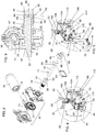
- the actuator assembly 34 includes a motor 40, a crank 42, and a driving shaft 44 defining a substantially longitudinal driving shaft rotation axis 46.
- the actuator assembly 34 also includes an actuator body 47 to which the motor 40, crank 42, and driving shaft 44 are mounted.
- the actuator assembly 34 is configurable between a motorized configuration and a manual configuration, seen for example respectively in FIGS. 4 and 5 .
- the motor 40 is mechanically coupled to the driving shaft 44 for selectively rotating the driving shaft 44 about the driving shaft rotation axis 46 when the motor 40 is powered.
- the motor 40 is uncoupled from the driving shaft 44 and the crank 42 is mechanically coupled to the driving shaft 44 so that the crank 42 is usable to selectively rotate the driving shaft 44 independently of the motor 40. More details regarding the structure and operation of the actuator assembly 34 are provided hereinbelow.
- the motor 40 is any suitable motor, such as for example and non-limitingly an electrical motor, an hydraulic motor or a pneumatic motor connected to a suitable power supply and to a controller (both not shown in the drawings) in a conventional manner.
- the controller allows to selectively cause the motor 40 to turn in a selected direction by suitably powering the motor 40, and to selectively remove power to the motor 40.
- the transmission assembly 36 is provided between the actuator assembly 34 and the rod 32.
- the transmission assembly 36 is operatively coupled to the actuator assembly 34 and to the rod 32 for transmitting rotations of the driving shaft 44 to the rod 32 so that rotation of the driving shaft 44 about the driving shaft rotation axis 46 causes rotation of the rod 32 about the rod longitudinal axis 38. More details regarding the structure and operation of the transmission assembly 36 are provided hereinbelow.
- Rotating the rod 32 using the actuator assembly 34 to roll the tarpaulin 12 therearound moves the rod 32 towards the rod first position to move the tarpaulin 12 to the tarpaulin retracted configuration.
- Rotating the rod 32 using the actuator assembly 34 to unroll the tarpaulin 12 therefrom moves the rod 32 towards the rod second position to move the tarpaulin 12 to the tarpaulin extended configuration.
- At least one biasing element 48 is operatively coupled to the rod 32 for biasing the rod 32 towards the rod second position.
- the tarpaulin 12 is not rigid enough to push the rod 32 towards the rod second position when the tarpaulin 12 is unrolled from the rod 32. Therefore, this movement must be caused separately, for example using the biasing element 48.
- this movement may be provided in any other suitable manner, for example passively if the tarpaulin is rigid enough, or under the action of gravity if the top aperture peripheral edge 22 is slanted.
- a motor may be used to move the rod 32 towards the rod second position. Movements of the rod 32 towards the rod first position are usually automatically achieved are rolling the tarpaulin 12 around the rod 32 reduces a distance between the rod and the aperture first end 24.
- actuator assembly 34 an exemplary embodiment of the actuator assembly 34 is now described in greater details.
- the reader skilled in the art will appreciate that different actuator assemblies are within the scope of the appended claims. Non-limiting examples of alternative actuator assemblies are described hereinbelow.
- the motor 40 is not directly coupled to the driving shaft 44.
- the actuator assembly 34 includes an intermediate shaft 52 mechanically coupled to the motor 40 so as to be rotatable thereby and a shaft coupling element 54.
- the intermediate shaft 52 defines a shaft passageway 53 extending longitudinally therethrough coaxially with the driving shaft rotation axis 46.
- the driving shaft 44 extends in the shaft passageway 53 and protrudes therefrom.
- the driving shaft 44 protrudes at both ends from the shaft passageway 53.
- the driving shaft 44 may protrude only at one end thereof from the shaft passageway 53.
- the shaft coupling element 54 is movable between coupling and uncoupling configurations, seen respectively in FIGS. 9 and 10 .
- the shaft coupling element 54 couples the intermediate shaft 52 and driving shaft 44 to each other so that the motor 40 and driving shafts 44 are jointly rotatable about the driving shaft rotation axis 46.
- the driving shaft 44 is rotatable about the driving shaft rotation axis 46 independently from the intermediate shaft 52, and therefore independently from the motor 40.
- the shaft coupling element 54 may take any suitable form.
- the shaft coupling element 54 takes the form of an element that may selectively couple the driving and intermediate shafts 44 and 52 to each other so that the intermediate shafts 44 and 52 are jointly rotatable.
- intermediate shaft 52 defines an intermediate shaft coupling portion 56 and the driving shaft 44 defines a driving shaft coupling portion 58.
- the shaft coupling element 54 secures the intermediate and driving shaft coupling portions 56 and 58 to each other in the coupling configuration. In the uncoupling configuration, the intermediate and driving shaft coupling portions 56 and 58 are free to rotate relative to each other. Typically, the intermediate and driving shaft coupling portions 56 and 58 are substantially adjacent to each other.
- the intermediate shaft 52 includes a substantially cylindrical intermediate shaft main portion 57 and the intermediate shaft coupling portion 56 extends integrally from the intermediate shaft main portion 57 at one end thereof so that the intermediate shaft main portion 57 and intermediate shaft coupling portion 56 are jointly rotatable.
- the driving shaft 44 includes a substantially cylindrical driving shaft main portion 59 and the driving shaft coupling portion 58 extends integrally from the driving shaft main portion 59 at one end thereof so that the driving shaft main portion 59 and driving shaft coupling portion 58 are jointly rotatable.
- the driving shaft main portion 59 extends through the intermediate shaft coupling and main portions 56 and 57 and the driving shaft coupling portion 58 protrudes from the intermediate shaft 52.
- the shaft coupling element 54 includes a collar 60.
- the collar 60 receives thereinto and overlaps at least part of each of the intermediate and driving shaft coupling portions 56 and 58 in the coupling configuration. In the uncoupling configuration, the collar 60 is completely removed from the intermediate and driving shaft coupling portions 56 and 58, or overlaps only one of the intermediate and driving shaft coupling portions 56 and 58.
- the collar 60 may be coupled to the intermediate and driving shaft coupling portions 56 and 58 in any suitable manner in the coupling configuration to ensure that the intermediate and driving shaft coupling portions 56 and 58 are jointly rotatable.
- the intermediate and driving shaft coupling portions 56 and 58 each have a transversal cross-sectional configuration lacking continuous rotational symmetry, such as, for example and non-limitingly, a substantially polygonal transversal cross-sectional configuration.
- the intermediate and driving shaft coupling portions 56 and 58 each have a transversal cross-sectional configuration that differs from a circle.
- the collar 60 is hollow and substantially fittingly receives the intermediate and driving shaft coupling portions 56 and 58 so that in the coupling configuration, the collar 60 is jointly rotatable about the driving shaft rotation axis 46 along with the intermediate and driving shafts 52 and 44.
- the shaft coupling element 54 is selectively lockable in the coupling configuration. However, in other embodiments, this is not the case. More specifically, for example, the shaft coupling element 54 also includes a locking pin 64. At least one of the intermediate and driving shaft coupling portions 56 and 58, the driving shaft coupling portion 58 in the embodiment shown in the drawings, defines a pin receiving aperture 66 extending laterally therethrough and the collar 60 defines a pair of collar apertures 68 extending laterally therethrough laterally opposed to each other. In the coupling configuration, the collar apertures 68 are in register with the pin receiving aperture 66 and the locking pin 64 is insertable through both the collar apertures 68 and the pin receiving aperture 66 to lock the shaft coupling element 54 in the coupling configuration. Removing the locking pin 64 from the the collar apertures 68 and the pin receiving aperture 66 then allows to slide the collar 60 relative to the intermediate and driving shaft coupling portions 56 and 58 to achieve the uncoupling configuration.
- the motor 40 is coupled to the intermediate shaft 52 in any suitable manner.
- the motor 40 includes a motor output shaft 70 and a worm gear 72 extends between the motor output shaft 70 and the intermediate shaft 52 coupling the motor 40 and the intermediate shaft 52 to each other so that the motor 40 can rotate the intermediate shaft 52.
- the worm gear 72 includes a worm 74 driven by the motor output shaft 70 and a worm wheel 76 extending radially outwardly from the intermediate shaft 52 and jointly rotatable therewith.
- the worm 74 engages the worm wheel 76.
- the worm wheel 76 is permanently engaged with the worm 74 during normal operation of the device 10, whether the actuator assembly 34 is in the motorized or manual configurations.
- the actuator body 47 is configured to securely mount thereto the motor 40, worm gear 72, intermediate shaft 52 and driving shaft 44.
- the actuator body 47 is mounted to the container 14 in any suitable manner. An example of such a suitable manner is further described hereinbelow.
- crank 42 In the manual configuration, the crank 42 is secured to the driving shaft 44, as seen in FIG. 5 . In some embodiments, not shown in the drawings, the crank 42 is permanently secured to the driving shaft 44. However, in other embodiments, as illustrated in the drawings, the crank 42 is removably mountable to the remainder of the actuator assembly 34.
- the crank 42 includes a crank attachment portion 78, a crank handle 80 and a crank spacing portion 82 extending therebetween.
- the crank attachment portion 78 is mountable to a protruding portion of the driving shaft 44 that protrudes from the intermediate shaft 52 opposite to the transmission assembly 36.
- the crank attachment portion 78 is removably mountable to the driving shaft coupling portion 58 when the collar 60 is withdrawn therefrom.
- the crank attachment portion 78 defines a crank aperture 84 substantially snugly receiving the driving shaft coupling portion 58.
- the device 10 defines a crank receiving element 86, for example a collar opening substantially vertically, for receiving the crank 42 thereinto when the crank 42 is detached from the driving shaft 44.
- the crank receiving element is configured to that the crank attachment portion 78 and crank spacing portion 82 can be received therethrough, but so as to prevent the crank handle 80 from passing therethrough. Therefore, the crank 42 can be safely stowed when not in use.
- the transmission assembly 36 transmits the rotation of the driving shaft 44 to the rod 32.
- the actuator assembly 34 is provided close to the container bottom wall 16 so as to be relatively easily operable in the manual configuration.
- the transmission assembly 36 must therefore transmit this rotation of the driving shaft 44 up to the rod 32, which is provided adjacent the container top aperture 20.
- the transmission assembly 36 is configured and sized so that a distance between the driving shaft 44 and the rod 32 remains substantially constant as the rod 32 moves between the rod first and second positions. This may require in some embodiments that the actuator assembly 34 be mounted so as to be movable relative to the container 10.
- the transmission assembly includes an elongated arm 90 defining an arm longitudinal axis 92.
- the arm 90 defines substantially opposed arm first and second ends 94 and 96, seen for example respectively in FIGS. 4 and 13 .
- the arm first end 94 is substantially adjacent to the driving shaft 44.
- the arm second end 96 is substantially adjacent to the rod 32.
- the arm 90 is operatively coupled to the driving shaft 44 and rod 32 so that rotation of the driving shaft 44 about the driving shaft rotation axis (not shown in FIG.
- the arm 90 causes rotation of the arm 90 about the arm longitudinal axis 92, which in turn causes rotation of the rod 32 about the rod longitudinal axis 38.
- the arm 90 extends substantially perpendicular to the rod 32 and is pivotable relative to the driving shaft 44 between arm first and second positions, shown respectively in FIGS. 2 and 3 , wherein the rod 32 is respectively in the rod first and second positions.
- the arm 90 is a fixed length arm so that a distance between the driving shaft 44 and the rod 32 is fixed.
- the arm 90 may be a telescopic arm having a variable length.
- the actuator assembly 34 may be fixed relative to the container 14.
- the transmission assembly 36 also includes gearboxes and other components that allow pivotal movements of the arm 90 and allow transmission of the rotation of the driving shaft 44 to the rod 32.
- the driving shaft 44 is substantially horizontal and the transmission assembly includes a first 90 degrees gearbox 100 between the arm 90 and the driving shaft 44 and a second 90 degrees gearbox 102 between the arm 90 and the rod 32.
- the arm 32 is coupled to the first 90 degrees gearbox 100 using a universal joint 104 to allow pivotal movement of the arm 90 between the arm first and second positions as the rod 32 moves between the rod first and second positions.
- the path of the rod 32 between the rod first and second positions differs from an arc segment centered on the universal joint 104 with a radius of curvature equal to the length of the arm 90. Therefore, the arm 90 needs to be telescopic, or the location about which the arm 90 pivots needs to move relative to the container 14. This last option is illustrated in the drawings.
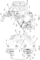
- the device 10 includes a mounting bracket 106 secured to the transmission assembly 34 for mounting the transmission assembly 36 to the container peripheral wall 18.
- the mounting bracket 106 is configured and sized for allowing vertical movements the arm 90 relative to the container peripheral wall 18. This is achieved by suitably mounting part of the transmission assembly 36 thereto.
- the actuator assembly 34 is also mounted to the mounting bracket 106.
- the mounting bracket 106 includes a base 108 fixedly secured to the container peripheral wall 18 (not shown in FIG. 7 , and a bracket mobile portion 110 movable vertically relative to the container 14.
- the arm 90 is mechanically coupled to the bracket mobile portion 110 at the arm first end 94 so that the arm first end 94 is vertically movable along with the bracket mobile portion 110, for example through the first 90 degrees gearbox 100.
- the mounting bracket 106 also includes a pair of levers 112 extending substantially parallel to each other and vertically spaced apart from each other.
- two pairs of levers 112 are provided.
- the two pairs of levers 112 are substantially parallel to each other and spaced apart from each other in a direction leading between the container first and second ends 11 and 13 .
- Each lever 112 is pivotally mounted at one end 114 thereof to the base 108 and pivotally mounted at another end 116 thereof to the bracket mobile portion 110.
- the bracket mobile portion 110 takes for example the form of a frame to which other components may be secured.
- the actuator assembly 34 is mounted to the bracket mobile portion 110, along with part of the transmission assembly 36. More generally, one of the actuator and transmission assemblies 34 and 36 is mounted to the bracket mobile portion 110.
- the first 90 degrees gearbox 100 is mounted to the bracket mobile portion so as to be rotated by the actuator assembly 34.
- the base 108 is mounted to the container 14 on the container first side 15, for example substantially adjacent the container bottom wall 16 and substantially midway between the container first and second ends 11 and 13.
- any suitable container 14 may be used with the device 10.
- the tarpaulin 12 is supported by the container 14 when moving between the tarpaulin first and second positions.
- the container 14 defines at least one tarpaulin support 118 extending between the container first and second ends 11 and 13 across the container top aperture 20.
- the at least one tarpaulin support includes at least two arches 120 spaced apart from each other and each extending across the container top aperture 20 between the container first and second ends 11 and 13.
- three arches 120 are provided, one adjacent each of the container first and second sides 15 and 17, and a third one midway between the first two ones.
- any other suitable number of arches 120 is usable.
- Each arch 120 includes for example three rectilinear tubes joined sequentially to each other.
- the at least one tarpaulin support includes part of the top aperture peripheral edge 22 on which the rod 32 and/or tarpaulin 12 are supported.
- a support rod 122 is mounted to the tarpaulin 12 at a location intermediate the tarpaulin first and second ends 28 and 30.
- the support rod 122 is provided so that when the tarpaulin 12 is in the extended configuration, the support rod 122 is midway between the aperture first and second ends 24 and 26 and extends along substantially the distance between the container first and second sides 15 and 17.
- the support rod 122 is rolled around the rod 32 along with the tarpaulin 12 when the latter is sufficiently rolled around the rod 32.
- anchoring blocks 123 are provided.
- the device 10 may include a plurality of anchoring blocks 123 spaced apart from each other along the container top aperture 20 substantially adjacent the aperture second end 26.
- the anchoring blocks 123 are provided slightly below the aperture second end 26 and each define a recess 125, for example an inverted J-shaped recess 125.
- the recess 125 opens generally towards a plane containing the container bottom wall 16 when the anchoring blocks 123 are operatively mounted to the container 14 and the recess 125 is configured and sized for receiving the rod 32 thereinto when arm 90 is in the arm second position.
- FIGS. 11 to 13 illustrate respectively various biasing element 48b, 48 and 48a usable in the device 10.
- the device 10 typically includes two of these biasing elements 48, 48a and 48b, one provided at each end of the rod 32, but use of one or more than two biasing elements 48, 48a and 48b is within scope of the invention.
- all the biasing elements 48, 48a and 48b may be of the same type, or various types may be mixed in the same device 10. All the types of biasing elements 48, 48a and 48b are provided to pull the rod 32 towards the rod second position.
- the biasing element 48 includes a coil spring 124 mounted in a tubular body 126 fixed to the container 14. One end of the coil spring 124 is fixed relative tubular body 126 (not shown in the drawings), and a cable 128 extends from the other end of the coil spring 124.
- the cable 128 is rolled around the rod 32 so that it unrolls therefrom when the rod 32 is moved towards the rod first position and is rolled therearound when the rod 32 is moved towards the rod second position.
- a tension is present in the coil spring 124 so that the cable 128 pulls on the rod 32 towards the rod second position.
- the biasing element 48a includes a pulley 130 mounted rod 32 so as to be rotatable relative thereto.
- a torsion spring 132 extends between the pulley 130 and the rod 32.
- a cable 134 is rolled around the pulley 130 at one end thereof and is secured to the container 14 at the container second end 13 at the other end thereof.
- the torsion spring 132 is configured to exert a torque pulling on the cable 134 so that the cable 134 has a tendency to be rolled around the pulley 130, which biases the rod 32 towards the rod second position.
- the biasing element 48b includes a coil spring 136 mounted in the rod 32, which is hollow along at least part thereof.
- One end of the coil spring 136 is fixed longitudinally relative rod 32 (not shown in the drawings), and a cable 138 extends from the other end of the coil spring 136.
- the cable 138 protrudes from the rod 32 and is fixed to the container 14 at the container second end 13.
- a tension is present in the coil spring 136 so that the cable 138 pulls on the rod 32 towards the rod second position.
- Biasing elements similar to the biasing elements 48, 48a and 48b, and usable in the device 10 are further described in US Patents 6,595,594 issued July 22, 2003 and 7,506,912 issued March 24, 2009 , both issued to Royer, and US Patent Application Publication 20020021018 of Royer published February 21, 2002 .
- the device 10 works as follows. Taking for example as an initial configuration the configuration shown in FIG. 2 with the actuator assembly 34 in the motorized configuration, the arm 90 is in the arm first position. The rod 32 is thus in the rod first position with the tarpaulin 12 rolled therearound. The biasing element 48 biases the rod 32 towards the rod second position.
- the structure of the motor 40 and of the components linking the motor 40 to the rod 32 prevents the rod 32 from moving. It should be noted that in alternative embodiments other components, such as a lock, a clutch or a brake, prevent this movement instead.
- the intermediate shaft 52 is rotated through the worm gear 72. Since the shaft coupling element 54 is in the coupling configuration, the driving shaft 44 is then also rotated by the action of the motor 40, which turns the various elements of the transmission assembly 36 to rotate the rod 32 so that the tarpaulin 12 is released from the rod 32. The rod 32 is then free to move under the action of the biasing element 48 until the extended configuration is achieved.
- the bracket mobile portion 110 moves up and down due to the pivotal movement of the levers 112 as the tarpaulin moves between the tarpaulin retracted and extended configurations to endure that the rod 32 is always supported by the container 14. Retraction of the tarpaulin 12 is achieved by rotating the motor 40 in the opposite direction.
- the actuator assembly 34 is moved to the manual configuration by sliding the collar 60 so that the driving shaft 44 is free to rotate relative to the intermediate shaft 52. Then, the crank 42 is mounted to the driving shaft 44 and can be used to rotate the rod 32 in either direction.
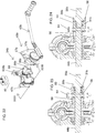
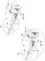
- FIGS. 16 to 18 illustrate an alternative actuator assembly 34a similar to the actuator assembly 34.
- the actuator assembly 34a is similar in structure and function to the actuator assembly 34 except that the driving shaft 44a is vertical and only needs to protrude from the intermediate shaft 52a at one end thereof. Since the driving shaft 44a is vertical, the first 90 degrees gearbox 100 can be omitted and the driving shaft 44a can be directly coupled to the universal joint 104.
- the driving shaft 44a is provided with a driving shaft gear 45a extending circumferentially therearound outside of the intermediate shaft 52, for example further away from the intermediate shaft coupling portion 56 than the driving shaft coupling portion 58.
- the crank 42 is part of a crank assembly 43a including a crank gear 39a and a crank assembly body 37a.
- the crank 42 is operatively coupled to the crank gear 39a for selectively rotating the crank gear 39a relative to the crank assembly body 37a.
- the crank assembly body 37a is mountable to a remainder of the actuator assembly 34a so that the crank 42 and driving shaft gears 45a are engaged with each other, for example perpendicular to each other, so that rotating the crank 42 is may rotate the driving shaft 44a.
- the crank assembly 43a includes a crank assembly shaft 35a rotatably mounted in a suitably located and configured mounting aperture 33a extending through the crank assembly body 37a.
- the crank assembly shaft 35a protrudes at both ends thereof from the crank assembly body 37a.
- the crank 42 and crank gear 39a are mounted at respective ends of the crank assembly shaft 35a so that the crank 42, crank assembly shaft 35a and crank gear 39a are jointly rotatable.
- the crank assembly body 37a is typically removably mountable to the remainder of the actuator assembly 34a so that when operatively mounted thereto, the crank gear 39a engages the driving shaft gear 45a so that rotating the crank gear 39a rotates the driving shaft gear 45a.
- the crank assembly body 37a defines a pair of opposed tongues 31a each slidably receivable in a respective substantially horizontal slit 29a when the crank assembly 44a is operatively mounted to the remainder of the actuator assembly 34a.
- the crank 42 can be rotated to rotate the driving shaft 44a, as in the embodiment of the actuator assembly 34 described hereinabove.
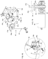
- FIGS. 21 to 24 illustrate an alternative actuator assembly 34b and an alternative transmission assembly 36b.
- the actuator assembly 34b is provided at one of the container first and second ends 11 and 13, to facilitate access to the crank 42b by an intended user. More specifically, instead of being mounted directly to the mounting bracket 106, the actuator assembly 34b is mounted to the container 14 substantially adjacent to one of the container first and second ends 11 and 13 (the container second end 13 in the specific example illustrated in the drawings).
- the transmission assembly 36b includes an intermediate gearbox 100b, replacing the first 90 degrees gearbox 100 and an extension shaft 140b.
- the extension shaft 140b extends between the driving shaft 44b and the intermediate gearbox 100b.
- the intermediate gearbox 100b is mounted to the bracket mobile portion 110, and the arm 90 is mounted to the intermediate gearbox 100b similarly to the manner in which the arm 90 is mounted to the first 90 degrees gearbox 100.
- the intermediate gearbox 100b is for example a 90 degrees gearbox.
- the actuator assembly 34b, extension shaft 140b, intermediate gearbox 100b and arm 90 are mechanically coupled to each other so that rotation of the driving shaft 44b about the driving shaft rotation axis 46 causes rotation of the arm 90 about the arm longitudinal axis 92.
- the extension shaft 140b is telescopic and is coupled to the driving shaft 44a and intermediate gearbox 100b with universal joints to accommodate vertical movements of the bracket mobile portion 110.
- FIG. 22 better illustrate the actuator assembly 34b.
- the actuator body 47b is provided with an actuator body mounting bracket 150b securable to the container 14 (not shown in FIG. 22 ).
- the crank 42b is part of a crank assembly 43b including a crank assembly shaft 35b rotatably mounted in a suitably located and configured mounting aperture (not shown in the drawings) extending through a crank assembly body 37b mountable to the container 14.
- the crank assembly shaft 35b may be mounted to the crank assembly body 37b using a bearing to facilitate its rotation.
- the actuator assembly 34b has any other suitable configuration and is mounted to the container 14 in any other suitable manner.
- crank assembly shaft 35b protrudes at both ends thereof from the crank assembly body 37b.
- the crank assembly shaft 35b may extend integrally from the driving shaft 44b, or, as shown in FIGS. 23 and 24 , may be coupled thereto axially through a bearing 31b opposed to the crank 42b (not shown in FIGS. 23 and 24 ).
- the bearing 31b allows the crank assembly shaft 35b and the driving shaft 44b to rotate freely relative to each other.
- the collar 60 is moved to overlap a crank shaft coupling portion 29b similar in cross-section to the driving shaft coupling portion 58, thereby allowing locked joint rotation of the crank assembly shaft 35b and driving shaft 44b.
- Motorized and manual configurations are illustrated in FIGS. 23 and 24 respectively.
- crank 42 When the bearing 31b is used, the crank 42 may be permanently left secured to the crank assembly shaft 35b as in motorized operation, the collar 60 is withdrawn from the crank shaft coupling portion 29b and rotation of the driving shaft 44b does not cause rotation of the crank assembly shaft 35b.
- the crank assembly 43b is provided with a conventional ratchet type mechanism 27b.
- the ratchet type mechanism 27b is configurable to prevent rotation of the crank 42b in an undesired direction, while allowing rotation of the crank 42b in the opposite direction.
- FIG. 20 illustrates yet another actuator and transmission assemblies 34c and 36c configuration.
- the actuator and transmission assemblies 34c and 36c are similar to the actuator and transmission assemblies 34b and 36b except that the extension shaft 140c is provided between the driving shaft 44c and the crank assembly shaft 35b, and is therefore part of the actuator assembly 34c instead of being part of the transmission assembly 36c.
- the driving shaft 44c is therefore directly attached to the intermediate gearbox 100c. Otherwise, the actuator and transmission assemblies 34c and 36c and the actuator and transmission assemblies 34b and 36b operate similarly and have similar structures.
- the motor 40, worm gear 72 and intermediate shaft 52 are omitted and that in these embodiments, the actuator assembly 34, 34a or 34b is completely manually operated.
- the actuator assembly may be similar to the actuator assembly 34, except for the absence of the components required for motorized operation.
- the actuator assembly 34d and transmission assembly 36d may be as illustrated in FIG. 19 , which is similar to the actuator assembly 34c and transmission assembly 36c, except that the the motor 40, worm gear 72 and intermediate shaft 52 are omitted.
- the extension shaft 104d is therefore coupled to the intermediate gearbox 100d for joint rotation therewith.
- an actuator assembly 34e is similar to the actuator assembly 34d except that the actuator assembly 34e includes a crank extension shaft 141e supporting the crank 42e.
- the crank extension shaft 141e is telescopic so as to be configurable between a retracted configuration (seen in FIG. 25 ) and an extended configuration (seen in FIG. 26 ).
- the crank 42e is retracted from the container second end 33 so that the crank 42e is not exposed when not needed.
- the crank 32e protrudes from the container second end 33 so that the crank 42e can be operated as described hereinabove.
- a crank securing member 143e is provided adjacent the crank 42e and engages a suitably shaped container securing member 145e to stabilize the crank 42e in the extended configuration.
Description
- The present invention relates generally to the field of transportation, and, more particularly, to a tarpaulin retraction and extension device usable for example with open top vehicle mounted containers.
- There are many systems for covering top apertures of truck-movable containers, such as open top truck trailers and the bin of dump trucks. Many such systems conveniently roll a tarpaulin covering the top aperture around a rod when the top aperture is uncovered. To facilitate operation of these system, many are provided with an electric motor. However, if the motor fails, the system becomes inoperable. One such device for manipulating a tarpaulin is disclosed in
US 201010230994 - Against this background, there exists a need for an improved tarpaulin extension and retraction device. An object of the present invention is to provide such a device.
- In a broad aspect there is provided a device for handling a tarpaulin to cover at least part of a container using the tarpaulin, the container defining a container bottom wall, a container peripheral wall extending therefrom and a container top aperture delimited by a container top edge of the container peripheral wall opposed to the container bottom wall, the container top aperture defining an aperture first end and an opposed aperture second end, the tarpaulin defining a tarpaulin first end and an opposed tarpaulin second end, the tarpaulin being secured to the container at the tarpaulin first end opposed to the aperture second end and movable between tarpaulin retracted and extended configurations in which the tarpaulin is respectively retracted from the container top aperture and extended across the container top aperture, the device comprising: a rod defining a rod longitudinal axis, the rod being movable between rod first and second positions wherein the rod is respectively adjacent the aperture first and second ends, the tarpaulin being mountable to the rod at the tarpaulin second end to allow rolling of the tarpaulin thereonto and unrolling of the tarpaulin therefrom when the rod is rotated about the rod longitudinal axis; an actuator assembly, the actuator assembly including a motor, a crank, and a driving shaft defining a longitudinal driving shaft rotation axis, the actuator assembly being configurable between a motorized configuration and a manual configuration, wherein, in the motorized configuration, the motor is mechanically coupled to the driving shaft for selectively rotating the driving shaft about the driving shaft rotation axis when the motor is powered, and, in the manual configuration, the motor is uncoupled from the driving shaft and the crank is mechanically coupled to the driving shaft so that the crank is usable to selectively rotate the driving shaft independently of the motor; and a transmission assembly between the actuator assembly and the rod, the transmission assembly being operatively coupled to the actuator assembly and to the rod for transmitting rotations of the driving shaft to the rod so that rotation of the driving shaft about the driving shaft rotation axis causes rotation of the rod about the rod longitudinal axis. Rotating the rod using the actuator assembly to roll the tarpaulin therearound moves the rod towards the rod first position to move the tarpaulin to the tarpaulin retracted configuration and rotating the rod using the actuator assembly to unroll the tarpaulin therefrom moves the rod towards the rod second position to move the tarpaulin to the tarpaulin extended configuration.
- There may also be provided a device further comprising a biasing element operatively coupled to the rod for biasing the rod towards the rod second position.
- In the present device, the actuator assembly includes an intermediate shaft mechanically coupled to the motor so as to be rotatable thereby, the intermediate shaft defining a shaft passageway extending longitudinally therethrough coaxially with the driving shaft rotation axis, the driving shaft extending in the shaft passageway and protruding therefrom, the actuator assembly further comprising a shaft coupling element movable between coupling and uncoupling configurations, wherein in the coupling configuration, the shaft coupling element couples the intermediate shaft and driving shaft to each other so that the motor and driving shafts are jointly rotatable about the driving shaft rotation axis, and in the uncoupling configuration, the driving shaft is rotatable about the driving shaft rotation axis independently from the intermediate shaft.
- There may also be provided a device wherein the intermediate shaft defines an intermediate shaft coupling portion and the driving shaft defines a driving shaft coupling portion, the shaft coupling element securing the intermediate and driving shaft coupling portions to each other in the coupling configuration.
- There may also be provided a device wherein the intermediate and driving shaft coupling portions are adjacent to each other.
- There may also be provided a devicewherein the shaft coupling element includes a collar, the collar receiving thereinto and overlapping at least part of each of the intermediate and driving shaft coupling portions in the locking configurations.
- There may also be provided a device wherein the intermediate and driving shaft coupling portions each have a transversal cross-sectional configuration lacking continuous rotational symmetry.
- There may also be provided a device wherein the intermediate and driving shaft coupling portions each have a polygonal transversal cross-sectional configuration.
- There may also be provided a device wherein the shaft coupling element is selectively lockable in the coupling configuration.
- There may also be provided a device wherein the shaft coupling element also includes a locking pin, the driving shaft coupling portions defining a pin receiving aperture extending laterally therethrough, the collar defining a pair of collar apertures extending laterally therethrough laterally opposed to each other, wherein, in the coupling configuration, the collar apertures are in register with the pin receiving aperture and the locking pin is insertable through both the collar apertures and the pin receiving aperture to lock the shaft coupling element in the coupling configuration.
- There may also be provided a device wherein the crank is removably mountable to a protruding portion of the driving shaft that protrudes from the intermediate shaft opposite to the transmission.
- There may also be provided a device wherein the device defines a crank receiving element for receiving the crank thereinto when the crank is detached from the protruding portion.
- There may also be provided a device wherein the driving shaft is provided with a driving shaft gear extending circumferentially therearound, the crank being part of a crank assembly including a crank gear and a crank assembly body, the crank being operatively coupled to the crank gear for selectively rotating the crank gear relative to the crank assembly body, the crank assembly body being mountable to a remainder of the actuator assembly so that the crank and driving shaft gears are engaged with each other so that rotation of the crank causes rotation of the driving shaft.
- There may also be provided a device further comprising a worm gear between the motor and the intermediate shaft coupling the motor and the intermediate shaft to each other so that the motor can rotate the intermediate shaft.
- There may also be provided a device wherein the worm gear includes a worm driven by the motor and a worm wheel extending radially outwardly from the intermediate shaft and jointly rotatable therewith.
- There may also be provided a device wherein the transmission assembly is configured and sized so that a distance between the driving shaft and the rod remains constant as the rod moves between the rod first and second positions.
- There may also be provided a device further comprising a mounting bracket secured to the actuator and transmission assemblies for mounting the actuator and transmission assemblies to the container peripheral wall, the mounting bracket being configured and sized for allowing vertical movements of the actuator and transmission assemblies relative to the container peripheral wall when the mounting bracket is secured to the container peripheral wall.
- There may also be provided a device wherein the mounting bracket includes a base fixedly securable to the container peripheral wall and a pair of levers extending parallel to each other and vertically spaced apart from each other, each lever being pivotally mounted at one end thereof to the base and pivotally mounted at another end thereof to one of the motor and transmission assemblies.
- There may also be provided a device wherein the transmission assembly includes an elongated arm defining an arm longitudinal axis, the arm defining opposed arm first and second ends, the arm first end being adjacent to the driving shaft and the arm second end being adjacent to the rod, the arm being operatively coupled to the driving shaft and rod so that rotation of the driving shaft about the driving shaft rotation axis causes rotation of the arm about the arm longitudinal axis, which in turn causes rotation of the rod about the rod longitudinal axis, the arm extending perpendicular to the rod and being pivotable relative to the driving shaft between arm first and second positions, wherein the rod is respectively in the rod first and second positions.
- There may also be provided a device wherein the arm is a fixed length arm.
- There may also be provided a device wherein the transmission assembly includes a first 90 degrees gearbox between the arm and the driving shaft and a second 90 degrees gearbox between the arm and the rod, the arm being coupled to the first 90 degrees gearbox using a universal joint to allow pivotal movement of the arm between the arm first and second positions as the rod moves between the rod first and second positions.
- In another broad aspect, there is provided a covered vehicle container, comprising: a container defining a container bottom wall, a container top aperture above the container bottom wall, opposed container first and second ends and opposed container first and second sides each extending between the container first and second ends, the container defining at least one tarpaulin support extending between the container first and second ends across the container top aperture; a tarpaulin defining tarpaulin first and second ends, the tarpaulin being secured to the container first end adjacent to the tarpaulin first end, the tarpaulin being movable between tarpaulin retracted and extended configurations in which the tarpaulin is respectively retracted from the container top aperture and extended across the container top aperture; and a device for handling the tarpaulin, the device including: a rod defining a rod longitudinal axis, the rod being movable between rod first and second positions wherein the rod is respectively adjacent the container first and second ends, the tarpaulin being mountable to the rod at the tarpaulin second end to allow rolling of the tarpaulin thereonto and unrolling of the tarpaulin therefrom when the rod is rotated about the rod longitudinal axis; an actuator assembly, the actuator assembly including a motor, a crank, and a driving shaft defining a longitudinal driving shaft rotation axis, the actuator assembly being configurable between a motorized configuration and a manual configuration, wherein, in the motorized configuration, the motor is mechanically coupled to the driving shaft for selectively rotating the driving shaft about the driving shaft rotation axis when the motor is powered, and, in the manual configuration, the motor is uncoupled from the driving shaft and the crank is mechanically coupled to the driving shaft so that the crank is usable to selectively rotate the driving shaft independently of the motor; a transmission assembly between the actuator assembly and the rod, the transmission assembly being operatively coupled to the actuator assembly and to the rod for transmitting rotations of the driving shaft to the rod so that rotation of the driving shaft about the driving shaft rotation axis causes rotation of the rod about the rod longitudinal axis; and a biasing element operatively coupled to the rod for biasing the rod towards the rod second position. Rotating the rod using the actuator assembly to roll the tarpaulin therearound moves the rod towards the rod first position to move the tarpaulin to the tarpaulin retracted configuration and rotating the rod using the actuator assembly to unroll the tarpaulin therefrom moves the rod towards the rod second position to move the tarpaulin to the tarpaulin extended configuration.
- There may also be provided a covered vehicle container wherein the actuator assembly includes an intermediate shaft mechanically coupled to the motor so as to be rotatable thereby, the intermediate shaft defining a shaft passageway extending longitudinally therethrough coaxially with the driving shaft rotation axis, the driving shaft extending in the shaft passageway and protruding therefrom, the actuator assembly further comprising a shaft coupling element movable between coupling and uncoupling configurations, wherein in the coupling configuration, the shaft coupling element couples the intermediate shaft and driving shaft to each other so that the motor and driving shafts are jointly rotatable about the driving shaft rotation axis, and in the uncoupling configuration, the driving shaft is rotatable about the driving shaft rotation axis independently from the intermediate shaft.
- There may also be provided a covered vehicle container wherein the intermediate shaft defines an intermediate shaft coupling portion and the driving shaft defines a driving shaft coupling portion, the shaft coupling element securing the intermediate and driving shaft coupling portions to each other in the coupling configuration.
- There may also be provided a covered vehicle container wherein the intermediate and driving shaft coupling portions are adjacent to each other and wherein the shaft coupling element includes a collar, the collar receiving thereinto and overlapping at least part of each of the intermediate and driving shaft coupling portions in the locking configurations.
- There may also be provided a covered vehicle container wherein the crank is removably mountable to a protruding portion of the driving shaft that protrudes from the intermediate shaft opposite to the transmission.
- There may also be provided a covered vehicle container wherein the driving shaft is provided with a driving shaft gear extending circumferentially around part thereof, the crank being part of a crank assembly including a crank gear and a crank assembly body, the crank being operatively coupled to the crank gear for selectively rotating the crank gear relative to the crank assembly body, the crank assembly body being removable mountable to a remainder of the drive assembly so that the crank and driving shaft gear are engaged to each other so that rotation of the crank is causes rotation the driving shaft.
- There may also be provided a covered vehicle container further comprising a worm gear between the motor and the intermediate shaft coupling the motor and the intermediate shaft to each other so that the motor can rotate the intermediate shaft.
- There may also be provided a covered vehicle container wherein the transmission assembly includes an elongated arm defining an arm longitudinal axis, the arm defining opposed arm first and second ends, the arm first end being adjacent to the container bottom wall and the arm second end being adjacent to the container top aperture, the arm being operatively coupled to the driving shaft and rod so that rotation of the driving shaft about the driving shaft rotation axis causes rotation of the arm about the arm longitudinal axis, which in turn causes rotation of the rod about the rod longitudinal axis, the arm extending perpendicular to the rod and being pivotable relative to the driving shaft between arm first and second positions, wherein the rod is respectively in the rod first and second positions.
- There may also be provided a covered vehicle container wherein the arm is a fixed length arm.
- There may also be provided a covered vehicle container further comprising a mounting bracket, the mounting bracket including a base fixedly mounted to the container and a bracket mobile portion movable vertically relative to the container, the arm being mechanically coupled to the bracket mobile portion at the arm first end so that the arm first end is vertically movable along with the bracket mobile portion.
- There may also be provided a covered vehicle container wherein the mounting bracket includes a pair of levers extending parallel to each other and vertically spaced apart from each other, each lever being pivotally mounted at one end thereof to the base and pivotally mounted at another end thereof to the bracket mobile portion.
- There may also be provided a covered vehicle container wherein the actuator assembly is mounted to the bracket mobile portion.
- There may also be provided a covered vehicle container wherein the base is mounted to the container on the container first side.
- There may also be provided a covered vehicle container wherein the base is mounted midway between the container first and second ends.
- There may also be provided a covered vehicle container wherein the actuator assembly is mounted to the container adjacent to one of the container first and second ends, the transmission including an intermediate gearbox and an extension shaft, the extension shaft extending between the driving shaft and the intermediate gearbox, the intermediate gearbox being mounted to the bracket mobile portion, and the arm being mounted to the intermediate gearbox, the actuator assembly, extension shaft, intermediate gearbox and arm being mechanically coupled to each other so that rotation of the driving shaft about the shaft longitudinal axis causes rotation of the arm about the arm longitudinal axis.
- There may also be provided a covered vehicle container wherein the actuator assembly includes a crank assembly, the crank assembly including the crank and a crank assembly shaft axially rotatable by the crank, the crank assembly shaft being coupled to the driving shaft axially through a bearing opposed to the crank, the bearing allowing the crank assembly shaft and the driving shaft to rotate freely relative to each other, the actuator assembly including a
collar 60 selectively movable so as to overlap jointly both the crank assembly shaft and driving shaft, the collar, crank assembly shaft and driving shaft being configured and sized so that with the collar overlapping the crank assembly shaft and driving shaft, the crank assembly shaft and driving shaft are jointly rotatable. - There may also be provided a covered vehicle container wherein the collar is further selectively movable so that the crank assembly shaft and driving shaft are rotatable independently from each other.
- There may also be provided a covered vehicle container wherein the motor and the driving shaft are mounted to the bracket mobile portion, the actuator assembly further including a crank shaft provided adjacent one of the container first and second ends, the crank being mounted to the crank shaft so as to rotate the latter about a crank shaft rotation axis, and extension shaft being provided between the crank shaft and the driving shaft to transmit rotations of the crank shaft to the driving shaft to rotate the latter.
- There may also be provided a covered vehicle container wherein the extension shaft is coupled to the driving and crank shafts with universal joints.
- There may also be provided a covered vehicle container wherein the transmission assembly includes a first 90 degrees gearbox between the arm and the driving shaft and a second 90 degrees gearbox between the arm and the rod, the arm being coupled to the first 90 degrees gearbox using a universal joint to allow pivotal movement of the arm between the arm first and second positions as the rod moves between the rod first and second positions.
- There may also be provided a covered vehicle container further comprising a support rod mounted to the tarpaulin so as to extend laterally thereacross at a location intermediate the tarpaulin first and second ends.
- There may also be provided a covered vehicle container wherein the at least one tarpaulin support includes at least two arches spaced apart from each other and each extending across the container top aperture between the container first and second ends.
- In yet another broad aspect of the present disclosure, there is provided a device for handling a tarpaulin over a container top aperture defining an aperture first end and an opposed aperture second end, the tarpaulin defining a tarpaulin first end and an opposed tarpaulin second end, the tarpaulin being secured to the container at the tarpaulin first end opposed to the aperture second end and movable between tarpaulin retracted and extended configurations in which the tarpaulin is respectively retracted from the container top aperture and extended across the container top aperture, the device comprising: a rod defining a rod longitudinal axis, the rod being movable between rod first and second positions wherein the rod is respectively adjacent the aperture first and second end, the tarpaulin being mountable to the rod at the tarpaulin second end to allow rolling of the tarpaulin thereonto and unrolling of the tarpaulin therefrom when the rod is rotated about the rod longitudinal axis; an actuator assembly, the actuator assembly including a motor, a crank, and a driving shaft defining a longitudinal driving shaft rotation axis, the actuator assembly being configurable between a motorized configuration and a manual configuration, wherein, in the motorized configuration, the motor is mechanically coupled to the driving shaft for selectively rotating the driving shaft about the driving shaft rotation axis when the motor is powered, and, in the manual configuration, the motor is uncoupled from the driving shaft and the crank is mechanically coupled to the driving shaft so that the crank is usable to selectively rotate the driving shaft independently of the motor; a transmission assembly between the actuator assembly and the rod, the transmission assembly being operatively coupled to the actuator assembly and to the rod for transmitting rotations of the driving shaft to the rod so that rotation of the driving shaft about the driving shaft rotation axis causes rotation of the rod about the rod longitudinal axis, the transmission assembly including an elongated arm defining an arm longitudinal axis, the arm defining opposed arm first and second ends, the arm first end being adjacent to the driving shaft and the arm second end being adjacent to the container top aperture, the arm being operatively coupled to the driving shaft and rod so that rotation of the driving shaft about the driving shaft rotation axis causes rotation of the arm about the arm longitudinal axis, which in turn causes rotation of the rod about the rod longitudinal axis, the arm extending perpendicular to the rod and being pivotable relative to the driving shaft between arm first and second positions, wherein the rod is respectively in the rod first and second positions; and a biasing element operatively coupled to the rod for biasing the rod towards the rod second position. Rotating the rod using the actuator assembly to roll the tarpaulin therearound moves the rod towards the rod first position to move the tarpaulin to the tarpaulin retracted configuration and rotating the rod using the actuator assembly to unroll the tarpaulin therefrom moves the rod towards the rod second position to move the tarpaulin to the tarpaulin extended configuration.
- In yet another broad aspect of the present disclosure, there is provided an actuator assembly, the actuator assembly including a motor, a crank, and a driving shaft defining a longitudinal driving shaft rotation axis, the actuator assembly being configurable between a motorized configuration and a manual configuration, wherein, in the motorized configuration, the motor is mechanically coupled to the driving shaft for selectively rotating the driving shaft about the driving shaft rotation axis when the motor is powered, and, in the manual configuration, the motor is uncoupled from the driving shaft and the crank is mechanically coupled to the driving shaft so that the crank is usable to selectively rotate the driving shaft independently of the motor.
- There may also be provided an actuator assembly wherein the actuator assembly includes an intermediate shaft mechanically coupled to the motor so as to be rotatable thereby, the intermediate shaft defining a shaft passageway extending longitudinally therethrough coaxially with the driving shaft rotation axis, the driving shaft extending in the shaft passageway and protruding therefrom, the actuator assembly further comprising a shaft coupling element movable between coupling and uncoupling configurations, wherein in the coupling configuration, the shaft coupling element couples the intermediate shaft and driving shaft to each other so that the motor and driving shafts are jointly rotatable about the driving shaft rotation axis, and in the uncoupling configuration, the driving shaft is rotatable about the driving shaft rotation axis independently from the intermediate shaft.
- There may also be provided an actuator assembly wherein the intermediate shaft defines an intermediate shaft coupling portion and the driving shaft defines a driving shaft coupling portion, the shaft coupling element securing the intermediate and driving shaft coupling portions to each other in the coupling configuration.
- There may also be provided an actuator assembly wherein the intermediate and driving shaft coupling portions are adjacent to each other.
- There may also be provided an actuator assembly wherein the shaft coupling element includes a collar, the collar receiving thereinto and overlapping at least part of each of the intermediate and driving shaft coupling portions in the locking configurations.
- There may also be provided an actuator assembly wherein the intermediate and driving shaft coupling portions each have a transversal cross-sectional configuration lacking continuous rotational symmetry.
- There may also be provided an actuator assembly wherein the intermediate and driving shaft coupling portions each have a polygonal transversal cross-sectional configuration.
- There may also be provided an actuator assembly wherein the shaft coupling element is selectively lockable in the coupling configuration.
- There may also be provided an actuator assembly wherein the shaft coupling element also includes a locking pin, the driving shaft coupling portions defining a pin receiving aperture extending laterally therethrough, the collar defining a pair of collar apertures extending laterally therethrough laterally opposed to each other, wherein, in the coupling configuration, the collar apertures are in register with the pin receiving aperture and the locking pin is insertable through both the collar apertures and the pin receiving aperture to lock the shaft coupling element in the coupling configuration.
- In yet another broad aspect of the present disclosure, the invention provides a device for handling a tarpaulin to cover at least part of a container using the tarpaulin, the container defining a container bottom wall, a container peripheral wall extending therefrom and a container top aperture delimited by a container top edge of the container peripheral wall opposed to the container bottom wall, the container top aperture defining an aperture first end and an opposed aperture second end, the tarpaulin defining a tarpaulin first end and an opposed tarpaulin second end, the tarpaulin being secured to the container at the tarpaulin first end opposed to the aperture second end and movable between tarpaulin retracted and extended configurations in which the tarpaulin is respectively retracted from the container top aperture and extended across the container top aperture, the device comprising: a rod defining a rod longitudinal axis, the rod being movable between rod first and second positions wherein the rod is respectively adjacent the aperture first and second ends, the tarpaulin being mountable to the rod at the tarpaulin second end to allow rolling of the tarpaulin thereonto and unrolling of the tarpaulin therefrom when the rod is rotated about the rod longitudinal axis; an actuator assembly, the actuator assembly including an actuator and a driving shaft rotatable about a longitudinal driving shaft rotation axis by the actuator; and a transmission assembly between the actuator assembly and the rod, the transmission assembly being operatively coupled to the actuator assembly and to the rod for transmitting rotations of the driving shaft to the rod so that rotation of the driving shaft about the driving shaft rotation axis by the actuator causes rotation of the rod about the rod longitudinal axis, the transmission assembly including an elongated arm defining an arm longitudinal axis, the arm defining opposed arm first and second ends, the arm first end being adjacent to the container bottom wall and the arm second end being adjacent to the container top aperture, the arm being operatively coupled to the driving shaft and rod so that rotation of the driving shaft about the driving shaft rotation axis by the actuator causes rotation of the arm about the arm longitudinal axis, which in turn causes rotation of the rod about the rod longitudinal axis, the arm extending perpendicular to the rod and being pivotable relative to the driving shaft between arm first and second positions, wherein the rod is respectively in the rod first and second positions. Wherein rotating the rod using the actuator assembly to roll the tarpaulin therearound moves the rod towards the rod first position to move the tarpaulin to the tarpaulin retracted configuration and rotating the rod using the actuator assembly to unroll the tarpaulin therefrom moves the rod towards the rod second position to move the tarpaulin to the tarpaulin extended configuration.
- There may also be provided a device wherein the arm is a fixed length arm.
- There may also be provided a device wherein the transmission assembly includes a first 90 degrees gearbox between the arm and the driving shaft and a second 90 degrees gearbox between the arm and the rod, the arm being coupled to the first 90 degrees gearbox using a universal joint to allow pivotal movement of the arm between the arm first and second positions as the rod moves between the rod first and second positions.
- There may also be provided a device wherein the actuator assembly includes a crank operatively coupled to the driving shaft for rotating the driving shaft about the driving shaft rotation axis.
- There may also be provided a device further comprising a mounting bracket secured to the actuator and transmission assemblies for mounting the actuator and transmission assemblies to the container, the mounting bracket being configured and sized for allowing vertical movements of the arm relative to the container peripheral wall.
- There may also be provided a device wherein the mounting bracket includes a base fixedly mountable to the container and a bracket mobile portion movable vertically relative to the base, the arm being mechanically coupled to the bracket mobile portion at the arm first end so that the arm first end is vertically movable along with the bracket mobile portion.
- There may also be provided a device wherein the transmission assembly includes a universal joint between the bracket mobile portion and the arm for allowing pivotal movements of the arm relative to the mounting bracket.
- Advantageously, in some embodiments, the proposed device can be manufactured using a relatively small quantity of materials. When the electric motor is disengaged from the driving shaft, the crank can be used to operate the proposed device manually using the crank. The device can therefore be operated if the motor is not powered or if the motor fails. In some embodiments, change between the manual and motorized configurations is achieved using a relatively small number of ergonomic steps.
- In some embodiments, the proposed device may automatically achieve the manual configuration from the motorized configuration when the crank is used, instead of requiring an action from the intended user.
- Other objects, advantages and features of the present invention will become more apparent upon reading of the following non-restrictive description of some embodiments thereof, given by way of example only with reference to the accompanying drawings.
-
-
Figure 1 , in a perspective view, illustrates a container and a device for handling a tarpaulin to cover at least part of a container using the tarpaulin in accordance with an embodiment of the present invention, the tarpaulin being shown in a configuration intermediate a retracted configuration and an extend configuration; -
Figure 2 , in a perspective view, illustrates the container and device ofFIG. 1 , the tarpaulin being shown in the retracted configuration; -
Figure 3 , in a perspective view, illustrates the container and device ofFIGS. 1 and2 , the tarpaulin being shown in the extended configuration; -
Figure 4 , in a perspective view, illustrates an actuator assembly part of the device ofFIGS. 1 to 3 , the actuator assembly being shown in a motorized configuration; -
Figure 5 , in a perspective view, illustrates the actuator assembly ofFIG. 4 , the actuator assembly being shown in a manual configuration; -
Figure 6 , in a side elevation view, illustrates a mounting bracket part of the device ofFIGS. 1 to 3 , along with the actuator assembly ofFIGS. 4 and 5 and part of a transmission assembly part of the device ofFIGS. 1 to 3 ; -
Figure 7 , in a perspective view, illustrates the mounting bracket ofFIG. 6 ; -
Figure 8 , in a partial perspective exploded view, illustrates the actuator assembly ofFIGS. 4 and 5 ; -
Figure 9 , in a cross-sectional view along section line IX-IX ofFIG. 7 , illustrates the actuator assembly ofFIGS. 4, 5 and 8 in the motorized configuration; -
Figure 10 , in a cross-sectional view along section line IX-IX ofFIG. 7 , illustrates the actuator assembly ofFIGS. 4, 5, 8 and 9 in the manual configuration; -
Figure 11 , in a partial perspective view, illustrates a first embodiment of a biasing element usable in the device ofFIGS. 1 to 3 ; -
Figure 12 , in a perspective view of bubble XII ofFIG. 1 , illustrates a second embodiment of a biasing element usable in the device ofFIGS. 1 to 3 ; -
Figure 13 , in a perspective view of bubble XIII ofFIG. 1 , illustrates a third embodiment of a biasing element usable in the device ofFIGS. 1 to 3 ; -
Figure 14 , in a perspective view of bubble XIV OFFIG. 1 , illustrates an arch part of the container ofFIGS. 1 to 3 ; -
Figure 15 , in a side cross-sectional view along section line XV-XV of FIG. XIV, illustrates the tarpaulin ofFIGS. 1 to 3 , a long with a support rod usable to support a middle portion of the tarpaulin when the letter is in a tarpaulin extended configuration; -
Figure 16 , in a perspective view, illustrates an alternative embodiment of an actuator assembly usable in the device ofFIGS. 1 to 3 , the actuator assembly being shown in a manual configuration; -
Figure 17 , in a perspective partially exploded view, illustrates the actuator assembly ofFIG. 16 ; -
Figure 18 , in a partial side-cross-sectional view, illustrates the actuator assembly ofFIGS. 16 and 17 in the motorized configuration; -
Figure 19 , in a perspective view, illustrates alternative embodiments of an actuator assembly and a transmission assembly usable in the device ofFIGS. 1 to 3 ; -
Figure 20 , in a perspective view, illustrates an other alternative embodiment of an actuator assembly and a transmission assembly usable in the device ofFIGS. 1 to 3 ; -
Figure 21 , in a perspective view, illustrates yet an other alternative embodiment of an actuator assembly and a transmission assembly usable in the device ofFIGS. 1 to 3 ; -
Figure 22 , in a perspective view, illustrates the actuator assembly ofFIG. 21 ; -
Figure 23 , in a cross-sectional view along section line XXIII-XXIII ofFIG. 22 , illustrates part of the actuator assembly ofFIG. 21 in the motorized configuration; -
Figure 24 , in a cross-sectional view along section line XXIII-XXIII ofFIG. 22 , illustrates part of the actuator assembly ofFIG. 22 in the manual configuration; -
Figure 25 , in a partial perspective view, illustrates yet an other alternative embodiment of an actuator assembly and a transmission assembly usable in the device ofFIGS. 1 to 3 shown here with a crank extension shaft thereof in a retracted configuration; and -
Figure 26 , in a partial perspective view, the actuator assembly ofFIG. 25 shown here with the crank extension shaft in an extended configuration; - Referring to
FIG. 1 for example, there is shown adevice 10 for handling atarpaulin 12 to cover at least part of acontainer 14 using thetarpaulin 12. Typically, thecontainer 14 defines acontainer bottom wall 16, a containerperipheral wall 18 extending therefrom and acontainer top aperture 20 delimited by a container top edge 19 of the containerperipheral wall 18 substantially opposed to thecontainer bottom wall 16. The present invention is however also usable to cover other structures that may lack thecontainer bottom wall 16 or part of the containerperipheral wall 18. - The
container top aperture 20 defines an aperturefirst end 24 and a substantially opposed aperturesecond end 26. Thetarpaulin 12 defines a tarpaulinfirst end 28 and a substantially opposed tarpaulinsecond end 30, as seen for example inFIG. 15 . Thetarpaulin 12 is secured to thecontainer 14 at the tarpaulinfirst end 28 substantially opposed to the aperturesecond end 26 and is movable between tarpaulin retracted and extended configurations in which thetarpaulin 12 is respectively substantially retracted from the container top aperture and 20 extended across thecontainer top aperture 20, as seen respectively inFIGS. 2 and3 . - Returning to
FIG. 1 , thecontainer 14 defines opposed container first and second ends 11 and 13 and opposed container first andsecond sides - The
container 14 is typically part of a vehicle or a trailer to be pulled by a vehicle. For example, thecontainer 14 is mountable on a platform truck, an open top truck trailer or the bin of a dump truck, among other possibilities. However, thedevice 10 is usable with othersuitable containers 14. In some embodiments, thedevice 10 is usable to cover a railroad car. - It should be noted that the aperture first and second ends 24 and 26 are not necessarily at the front or rear of the
container 14, front and rear being related to the direction in which thecontainer 14 is moved by the vehicle. As shown in the drawings, the aperture first and second ends 24 and 26 may be on edges of thecontainer 14 that extend parallel to the direction of motion of thecontainer 14 in typical operation. In the context of amovable container 14,FIGS. 1 to 3 illustrate a case in which thecontainer 14 is moved in a direction perpendicular to a line joining the aperture first and second ends 24 and 26. Thetarpaulin 12 is therefore retracted laterally relative to the direction of motion. However, it is within the scope of the invention to havetarpaulins 12 retractable along the direction of motion. - The term "substantially" is used throughout this document to indicate variations in the thus qualifies terms. These variations are variations that do not materially affect the manner in which the invention works and can be due, for example, to uncertainty in manufacturing processes or to small deviations from a nominal value that do not cause significant changes to the invention. These variations are to be interpreted from the point of view of the person skilled in the art. Also, directional terminology such as below and horizontal, among others, is used in this document and refer to the
device 10 andcontainer 14 in a typical operational configuration. This terminology is used for clarity reasons and should not be used to restrict the scope of the appended claims unless explicitly mentioned in the claims. - The
tarpaulin 12 may be directly secured to thecontainer 14, or may be secured thereto indirectly, for example through anchoring straps (not shown in the drawings) that extend between thetarpaulin 12, at the tarpaulinfirst end 28 for example, and thecontainer 14. When present, the anchoring straps are secured to thecontainer 14, for example to the containerperipheral wall 18 below the aperturefirst end 24. Thetarpaulin 12 is secured to thecontainer 14 substantially opposed to the aperturesecond end 26 so that when extended, thetarpaulin 12 extends across thecontainer top aperture 20. To that effect, thetarpaulin 12 may be secured to the containerperipheral wall 18 below the aperturefirst end 24 or adjacent the aperturefirst end 24, among other possibilities. - The
device 10 includes arod 32, anactuator assembly 34 and atransmission assembly 36. Thetransmission assembly 36 is provided between therod 32 and theactuator assembly 34 and transmits rotation produced in theactuator assembly 34 to therod 32 so that the latter can be used to extend and withdraw thetarpaulin 12. - More specifically, the
rod 32 defines a rodlongitudinal axis 38. Therod 32 is movable between rod first and second positions, seen respectively inFIGS. 2 and3 , wherein therod 32 is respectively substantially adjacent the aperture first and second ends 24 and 26. Thetarpaulin 12 is mountable to therod 32 at the tarpaulinsecond end 30 to allow rolling of thetarpaulin 12 thereonto and unrolling of thetarpaulin 12 therefrom when therod 32 is rotated about the rodlongitudinal axis 38. For example, thetarpaulin 12 is secured to therod 32 at the tarpaulinsecond end 30 in a conventional manner. - As seen for example in
FIGS. 4 and 5 , theactuator assembly 34 includes amotor 40, acrank 42, and a drivingshaft 44 defining a substantially longitudinal drivingshaft rotation axis 46. In some embodiments, but not necessarily, theactuator assembly 34 also includes anactuator body 47 to which themotor 40, crank 42, and drivingshaft 44 are mounted. Theactuator assembly 34 is configurable between a motorized configuration and a manual configuration, seen for example respectively inFIGS. 4 and 5 . In the motorized configuration, themotor 40 is mechanically coupled to the drivingshaft 44 for selectively rotating the drivingshaft 44 about the drivingshaft rotation axis 46 when themotor 40 is powered. In the manual configuration, themotor 40 is uncoupled from the drivingshaft 44 and thecrank 42 is mechanically coupled to the drivingshaft 44 so that thecrank 42 is usable to selectively rotate the drivingshaft 44 independently of themotor 40. More details regarding the structure and operation of theactuator assembly 34 are provided hereinbelow. - The
motor 40 is any suitable motor, such as for example and non-limitingly an electrical motor, an hydraulic motor or a pneumatic motor connected to a suitable power supply and to a controller (both not shown in the drawings) in a conventional manner. The controller allows to selectively cause themotor 40 to turn in a selected direction by suitably powering themotor 40, and to selectively remove power to themotor 40. - The
transmission assembly 36 is provided between theactuator assembly 34 and therod 32. Thetransmission assembly 36 is operatively coupled to theactuator assembly 34 and to therod 32 for transmitting rotations of the drivingshaft 44 to therod 32 so that rotation of the drivingshaft 44 about the drivingshaft rotation axis 46 causes rotation of therod 32 about the rodlongitudinal axis 38. More details regarding the structure and operation of thetransmission assembly 36 are provided hereinbelow. - Rotating the
rod 32 using theactuator assembly 34 to roll thetarpaulin 12 therearound moves therod 32 towards the rod first position to move thetarpaulin 12 to the tarpaulin retracted configuration. Rotating therod 32 using theactuator assembly 34 to unroll thetarpaulin 12 therefrom moves therod 32 towards the rod second position to move thetarpaulin 12 to the tarpaulin extended configuration. By selecting the manual or motorized configuration of theactuator assembly 34, thedevice 10 can be operated respectively manually, without an external power source, and motorized, by energizing themotor 40 with a suitable power source. - Returning to
FIG. 1 , typically, at least one biasingelement 48 is operatively coupled to therod 32 for biasing therod 32 towards the rod second position. Indeed, in a typical embodiment, thetarpaulin 12 is not rigid enough to push therod 32 towards the rod second position when thetarpaulin 12 is unrolled from therod 32. Therefore, this movement must be caused separately, for example using the biasingelement 48. However, in alternative embodiments, this movement may be provided in any other suitable manner, for example passively if the tarpaulin is rigid enough, or under the action of gravity if the top aperture peripheral edge 22 is slanted. In yet other embodiments, a motor may be used to move therod 32 towards the rod second position. Movements of therod 32 towards the rod first position are usually automatically achieved are rolling thetarpaulin 12 around therod 32 reduces a distance between the rod and the aperturefirst end 24. - Referring to
FIGS. 8, 9 and10 , an exemplary embodiment of theactuator assembly 34 is now described in greater details. The reader skilled in the art will appreciate that different actuator assemblies are within the scope of the appended claims. Non-limiting examples of alternative actuator assemblies are described hereinbelow. - In the
actuator assembly 34, themotor 40 is not directly coupled to the drivingshaft 44. Instead, theactuator assembly 34 includes anintermediate shaft 52 mechanically coupled to themotor 40 so as to be rotatable thereby and ashaft coupling element 54. Theintermediate shaft 52 defines ashaft passageway 53 extending longitudinally therethrough coaxially with the drivingshaft rotation axis 46. The drivingshaft 44 extends in theshaft passageway 53 and protrudes therefrom. In theactuator assembly 34, the drivingshaft 44 protrudes at both ends from theshaft passageway 53. However, in other embodiments the drivingshaft 44 may protrude only at one end thereof from theshaft passageway 53. - The
shaft coupling element 54 is movable between coupling and uncoupling configurations, seen respectively inFIGS. 9 and10 . In the coupling configuration, theshaft coupling element 54 couples theintermediate shaft 52 and drivingshaft 44 to each other so that themotor 40 and drivingshafts 44 are jointly rotatable about the drivingshaft rotation axis 46. In the uncoupling configuration, the drivingshaft 44 is rotatable about the drivingshaft rotation axis 46 independently from theintermediate shaft 52, and therefore independently from themotor 40. - The
shaft coupling element 54 may take any suitable form. Theshaft coupling element 54 takes the form of an element that may selectively couple the driving andintermediate shafts intermediate shafts - For example, and non-limitingly,
intermediate shaft 52 defines an intermediateshaft coupling portion 56 and the drivingshaft 44 defines a drivingshaft coupling portion 58. Theshaft coupling element 54 secures the intermediate and drivingshaft coupling portions shaft coupling portions shaft coupling portions - For example, the
intermediate shaft 52 includes a substantially cylindrical intermediate shaftmain portion 57 and the intermediateshaft coupling portion 56 extends integrally from the intermediate shaftmain portion 57 at one end thereof so that the intermediate shaftmain portion 57 and intermediateshaft coupling portion 56 are jointly rotatable. Similarly, the drivingshaft 44 includes a substantially cylindrical driving shaftmain portion 59 and the drivingshaft coupling portion 58 extends integrally from the driving shaftmain portion 59 at one end thereof so that the driving shaftmain portion 59 and drivingshaft coupling portion 58 are jointly rotatable. The driving shaftmain portion 59 extends through the intermediate shaft coupling andmain portions shaft coupling portion 58 protrudes from theintermediate shaft 52. - In a specific embodiment, the
shaft coupling element 54 includes acollar 60. Thecollar 60 receives thereinto and overlaps at least part of each of the intermediate and drivingshaft coupling portions collar 60 is completely removed from the intermediate and drivingshaft coupling portions shaft coupling portions - The
collar 60 may be coupled to the intermediate and drivingshaft coupling portions shaft coupling portions shaft coupling portions shaft coupling portions collar 60 is hollow and substantially fittingly receives the intermediate and drivingshaft coupling portions collar 60 is jointly rotatable about the drivingshaft rotation axis 46 along with the intermediate and drivingshafts - In some embodiments, the
shaft coupling element 54 is selectively lockable in the coupling configuration. However, in other embodiments, this is not the case. More specifically, for example, theshaft coupling element 54 also includes a lockingpin 64. At least one of the intermediate and drivingshaft coupling portions shaft coupling portion 58 in the embodiment shown in the drawings, defines apin receiving aperture 66 extending laterally therethrough and thecollar 60 defines a pair ofcollar apertures 68 extending laterally therethrough laterally opposed to each other. In the coupling configuration, thecollar apertures 68 are in register with thepin receiving aperture 66 and the lockingpin 64 is insertable through both thecollar apertures 68 and thepin receiving aperture 66 to lock theshaft coupling element 54 in the coupling configuration. Removing the lockingpin 64 from the thecollar apertures 68 and thepin receiving aperture 66 then allows to slide thecollar 60 relative to the intermediate and drivingshaft coupling portions - The
motor 40 is coupled to theintermediate shaft 52 in any suitable manner. For example, referring toFIG. 8 , themotor 40 includes amotor output shaft 70 and aworm gear 72 extends between themotor output shaft 70 and theintermediate shaft 52 coupling themotor 40 and theintermediate shaft 52 to each other so that themotor 40 can rotate theintermediate shaft 52. Theworm gear 72 includes aworm 74 driven by themotor output shaft 70 and aworm wheel 76 extending radially outwardly from theintermediate shaft 52 and jointly rotatable therewith. Theworm 74 engages theworm wheel 76. Typically, but not exclusively, theworm wheel 76 is permanently engaged with theworm 74 during normal operation of thedevice 10, whether theactuator assembly 34 is in the motorized or manual configurations. - The
actuator body 47 is configured to securely mount thereto themotor 40,worm gear 72,intermediate shaft 52 and drivingshaft 44. Theactuator body 47 is mounted to thecontainer 14 in any suitable manner. An example of such a suitable manner is further described hereinbelow. - In the manual configuration, the
crank 42 is secured to the drivingshaft 44, as seen inFIG. 5 . In some embodiments, not shown in the drawings, thecrank 42 is permanently secured to the drivingshaft 44. However, in other embodiments, as illustrated in the drawings, thecrank 42 is removably mountable to the remainder of theactuator assembly 34. - For example, the
crank 42 includes acrank attachment portion 78, a crankhandle 80 and a crankspacing portion 82 extending therebetween. Thecrank attachment portion 78 is mountable to a protruding portion of the drivingshaft 44 that protrudes from theintermediate shaft 52 opposite to thetransmission assembly 36. For example, thecrank attachment portion 78 is removably mountable to the drivingshaft coupling portion 58 when thecollar 60 is withdrawn therefrom. To that effect, thecrank attachment portion 78 defines acrank aperture 84 substantially snugly receiving the drivingshaft coupling portion 58. When thecrank 42 is mounted to the drivingshaft coupling portion 58, the crank handle 80 is offset from the drivingshaft rotation axis 46 and can be rotated about the drivingshaft rotation axis 46 to turn the drivingshaft 44 thereabout. - In some embodiments, The
device 10 defines acrank receiving element 86, for example a collar opening substantially vertically, for receiving thecrank 42 thereinto when thecrank 42 is detached from the drivingshaft 44. The crank receiving element is configured to that thecrank attachment portion 78 and crankspacing portion 82 can be received therethrough, but so as to prevent the crank handle 80 from passing therethrough. Therefore, the crank 42 can be safely stowed when not in use. - The
transmission assembly 36 transmits the rotation of the drivingshaft 44 to therod 32. In some embodiments, theactuator assembly 34 is provided close to thecontainer bottom wall 16 so as to be relatively easily operable in the manual configuration. Thetransmission assembly 36 must therefore transmit this rotation of the drivingshaft 44 up to therod 32, which is provided adjacent thecontainer top aperture 20. - In some embodiments, the
transmission assembly 36 is configured and sized so that a distance between the drivingshaft 44 and therod 32 remains substantially constant as therod 32 moves between the rod first and second positions. This may require in some embodiments that theactuator assembly 34 be mounted so as to be movable relative to thecontainer 10. - More specifically, with reference to
FIG. 1 , in a specific embodiment, the transmission assembly includes anelongated arm 90 defining an armlongitudinal axis 92. Thearm 90 defines substantially opposed arm first and second ends 94 and 96, seen for example respectively inFIGS. 4 and13 . As better seen inFIG. 4 , The armfirst end 94 is substantially adjacent to the drivingshaft 44. As better seen inFIG. 13 , the arm second end 96 is substantially adjacent to therod 32. Returning toFIG. 1 , thearm 90 is operatively coupled to the drivingshaft 44 androd 32 so that rotation of the drivingshaft 44 about the driving shaft rotation axis (not shown inFIG. 1 ) causes rotation of thearm 90 about the armlongitudinal axis 92, which in turn causes rotation of therod 32 about the rodlongitudinal axis 38. Thearm 90 extends substantially perpendicular to therod 32 and is pivotable relative to the drivingshaft 44 between arm first and second positions, shown respectively inFIGS. 2 and3 , wherein therod 32 is respectively in the rod first and second positions. - In some embodiments, as shown in the drawings, the
arm 90 is a fixed length arm so that a distance between the drivingshaft 44 and therod 32 is fixed. However, in other embodiments, thearm 90 may be a telescopic arm having a variable length. In such embodiments, theactuator assembly 34 may be fixed relative to thecontainer 14. - The
transmission assembly 36 also includes gearboxes and other components that allow pivotal movements of thearm 90 and allow transmission of the rotation of the drivingshaft 44 to therod 32. For example, the drivingshaft 44 is substantially horizontal and the transmission assembly includes a first 90degrees gearbox 100 between thearm 90 and the drivingshaft 44 and a second 90degrees gearbox 102 between thearm 90 and therod 32. Thearm 32 is coupled to the first 90degrees gearbox 100 using auniversal joint 104 to allow pivotal movement of thearm 90 between the arm first and second positions as therod 32 moves between the rod first and second positions. - In some embodiments, the path of the
rod 32 between the rod first and second positions differs from an arc segment centered on theuniversal joint 104 with a radius of curvature equal to the length of thearm 90. Therefore, thearm 90 needs to be telescopic, or the location about which thearm 90 pivots needs to move relative to thecontainer 14. This last option is illustrated in the drawings. - More specifically, the
device 10 includes a mountingbracket 106 secured to thetransmission assembly 34 for mounting thetransmission assembly 36 to the containerperipheral wall 18. The mountingbracket 106 is configured and sized for allowing vertical movements thearm 90 relative to the containerperipheral wall 18. This is achieved by suitably mounting part of thetransmission assembly 36 thereto. In some embodiments, theactuator assembly 34 is also mounted to the mountingbracket 106. - Referring for example to
FIG. 7 , the mountingbracket 106 includes a base 108 fixedly secured to the container peripheral wall 18 (not shown inFIG. 7 , and a bracketmobile portion 110 movable vertically relative to thecontainer 14. Thearm 90 is mechanically coupled to the bracketmobile portion 110 at the armfirst end 94 so that the armfirst end 94 is vertically movable along with the bracketmobile portion 110, for example through the first 90degrees gearbox 100. - The mounting
bracket 106 also includes a pair oflevers 112 extending substantially parallel to each other and vertically spaced apart from each other. In some embodiments of the invention, two pairs oflevers 112 are provided. The two pairs oflevers 112 are substantially parallel to each other and spaced apart from each other in a direction leading between the container first and second ends 11 and 13 . Eachlever 112 is pivotally mounted at oneend 114 thereof to thebase 108 and pivotally mounted at anotherend 116 thereof to the bracketmobile portion 110. - The bracket
mobile portion 110 takes for example the form of a frame to which other components may be secured. For example, theactuator assembly 34 is mounted to the bracketmobile portion 110, along with part of thetransmission assembly 36. More generally, one of the actuator andtransmission assemblies mobile portion 110. In the embodiment illustrates inFIGS. 6 and 7 , the first 90degrees gearbox 100 is mounted to the bracket mobile portion so as to be rotated by theactuator assembly 34. - As seen in
FIG. 1 , thebase 108 is mounted to thecontainer 14 on the containerfirst side 15, for example substantially adjacent thecontainer bottom wall 16 and substantially midway between the container first and second ends 11 and 13. - Any
suitable container 14 may be used with thedevice 10. Thetarpaulin 12 is supported by thecontainer 14 when moving between the tarpaulin first and second positions. To that effect, thecontainer 14 defines at least one tarpaulin support 118 extending between the container first and second ends 11 and 13 across thecontainer top aperture 20. For example, the at least one tarpaulin support includes at least twoarches 120 spaced apart from each other and each extending across thecontainer top aperture 20 between the container first and second ends 11 and 13. In a specific non-limiting embodiment of the invention, threearches 120 are provided, one adjacent each of the container first andsecond sides arches 120 is usable. Each arch 120 includes for example three rectilinear tubes joined sequentially to each other. In other embodiments (not shown in the drawings, the at least one tarpaulin support includes part of the top aperture peripheral edge 22 on which therod 32 and/ortarpaulin 12 are supported. - In some embodiments, a
support rod 122 is mounted to thetarpaulin 12 at a location intermediate the tarpaulin first and second ends 28 and 30. For example thesupport rod 122 is provided so that when thetarpaulin 12 is in the extended configuration, thesupport rod 122 is midway between the aperture first and second ends 24 and 26 and extends along substantially the distance between the container first andsecond sides FIG. 15 , thesupport rod 122 is rolled around therod 32 along with thetarpaulin 12 when the latter is sufficiently rolled around therod 32. - Also, in some embodiments, anchoring
blocks 123 are provided. Thedevice 10 may include a plurality of anchoringblocks 123 spaced apart from each other along thecontainer top aperture 20 substantially adjacent the aperturesecond end 26. The anchoring blocks 123 are provided slightly below the aperturesecond end 26 and each define arecess 125, for example an inverted J-shapedrecess 125. Therecess 125 opens generally towards a plane containing thecontainer bottom wall 16 when the anchoring blocks 123 are operatively mounted to thecontainer 14 and therecess 125 is configured and sized for receiving therod 32 thereinto whenarm 90 is in the arm second position. -
FIGS. 11 to 13 illustrate respectively various biasingelement device 10. Thedevice 10 typically includes two of these biasingelements rod 32, but use of one or more than two biasingelements element elements same device 10. All the types of biasingelements rod 32 towards the rod second position. - Referring to
FIG. 12 , there is shown the biasingelement 48. The biasingelement 48 includes acoil spring 124 mounted in atubular body 126 fixed to thecontainer 14. One end of thecoil spring 124 is fixed relative tubular body 126 (not shown in the drawings), and acable 128 extends from the other end of thecoil spring 124. Thecable 128 is rolled around therod 32 so that it unrolls therefrom when therod 32 is moved towards the rod first position and is rolled therearound when therod 32 is moved towards the rod second position. A tension is present in thecoil spring 124 so that thecable 128 pulls on therod 32 towards the rod second position. - Referring to
FIG. 13 , there is shown thebiasing element 48a. The biasingelement 48a includes apulley 130 mountedrod 32 so as to be rotatable relative thereto. Atorsion spring 132 extends between thepulley 130 and therod 32. Acable 134 is rolled around thepulley 130 at one end thereof and is secured to thecontainer 14 at the containersecond end 13 at the other end thereof. Thetorsion spring 132 is configured to exert a torque pulling on thecable 134 so that thecable 134 has a tendency to be rolled around thepulley 130, which biases therod 32 towards the rod second position. - Referring to
FIG. 11 , there is shown thebiasing element 48b. The biasingelement 48b includes acoil spring 136 mounted in therod 32, which is hollow along at least part thereof. One end of thecoil spring 136 is fixed longitudinally relative rod 32 (not shown in the drawings), and acable 138 extends from the other end of thecoil spring 136. Thecable 138 protrudes from therod 32 and is fixed to thecontainer 14 at the containersecond end 13. A tension is present in thecoil spring 136 so that thecable 138 pulls on therod 32 towards the rod second position. - Biasing elements similar to the biasing
elements device 10 are further described inUS Patents 6,595,594 issued July 22, 2003 and7,506,912 issued March 24, 2009 , both issued to Royer, andUS Patent Application Publication 20020021018 of Royer published February 21, 2002 . - In operation, the
device 10 works as follows. Taking for example as an initial configuration the configuration shown inFIG. 2 with theactuator assembly 34 in the motorized configuration, thearm 90 is in the arm first position. Therod 32 is thus in the rod first position with thetarpaulin 12 rolled therearound. The biasingelement 48 biases therod 32 towards the rod second position. However, the structure of themotor 40 and of the components linking themotor 40 to therod 32 prevents therod 32 from moving. It should be noted that in alternative embodiments other components, such as a lock, a clutch or a brake, prevent this movement instead. - When the
motor 40 is rotated in a suitable direction, theintermediate shaft 52 is rotated through theworm gear 72. Since theshaft coupling element 54 is in the coupling configuration, the drivingshaft 44 is then also rotated by the action of themotor 40, which turns the various elements of thetransmission assembly 36 to rotate therod 32 so that thetarpaulin 12 is released from therod 32. Therod 32 is then free to move under the action of the biasingelement 48 until the extended configuration is achieved. The bracketmobile portion 110 moves up and down due to the pivotal movement of thelevers 112 as the tarpaulin moves between the tarpaulin retracted and extended configurations to endure that therod 32 is always supported by thecontainer 14. Retraction of thetarpaulin 12 is achieved by rotating themotor 40 in the opposite direction. - If for any reason the
motor 40 cannot be used to operate thedevice 10, theactuator assembly 34 is moved to the manual configuration by sliding thecollar 60 so that the drivingshaft 44 is free to rotate relative to theintermediate shaft 52. Then, thecrank 42 is mounted to the drivingshaft 44 and can be used to rotate therod 32 in either direction. -
FIGS. 16 to 18 illustrate analternative actuator assembly 34a similar to theactuator assembly 34. Theactuator assembly 34a is similar in structure and function to theactuator assembly 34 except that the drivingshaft 44a is vertical and only needs to protrude from theintermediate shaft 52a at one end thereof. Since the drivingshaft 44a is vertical, the first 90degrees gearbox 100 can be omitted and the drivingshaft 44a can be directly coupled to theuniversal joint 104. - As seen for example in
FIG. 18 , the drivingshaft 44a is provided with a drivingshaft gear 45a extending circumferentially therearound outside of theintermediate shaft 52, for example further away from the intermediateshaft coupling portion 56 than the drivingshaft coupling portion 58. Referring toFIG. 17 , thecrank 42 is part of a crank assembly 43a including acrank gear 39a and acrank assembly body 37a. Thecrank 42 is operatively coupled to thecrank gear 39a for selectively rotating thecrank gear 39a relative to the crankassembly body 37a. Thecrank assembly body 37a is mountable to a remainder of theactuator assembly 34a so that thecrank 42 and driving shaft gears 45a are engaged with each other, for example perpendicular to each other, so that rotating thecrank 42 is may rotate the drivingshaft 44a. - For example, the crank assembly 43a includes a
crank assembly shaft 35a rotatably mounted in a suitably located and configured mountingaperture 33a extending through thecrank assembly body 37a. Thecrank assembly shaft 35a protrudes at both ends thereof from thecrank assembly body 37a. The crank 42 and crankgear 39a are mounted at respective ends of thecrank assembly shaft 35a so that thecrank 42, crankassembly shaft 35a and crankgear 39a are jointly rotatable. - The
crank assembly body 37a is typically removably mountable to the remainder of theactuator assembly 34a so that when operatively mounted thereto, thecrank gear 39a engages the drivingshaft gear 45a so that rotating thecrank gear 39a rotates the drivingshaft gear 45a. For example, thecrank assembly body 37a defines a pair ofopposed tongues 31a each slidably receivable in a respective substantiallyhorizontal slit 29a when thecrank assembly 44a is operatively mounted to the remainder of theactuator assembly 34a. When thecollar 60 is slid so that the drivingshaft 44a andintermediate shaft 52a are uncoupled from each other, the crank 42 can be rotated to rotate the drivingshaft 44a, as in the embodiment of theactuator assembly 34 described hereinabove. -
FIGS. 21 to 24 illustrate analternative actuator assembly 34b and analternative transmission assembly 36b. Referring toFIG. 21 , instead of being located substantially midway between the container first and second ends 11 and 13, theactuator assembly 34b is provided at one of the container first and second ends 11 and 13, to facilitate access to the crank 42b by an intended user. More specifically, instead of being mounted directly to the mountingbracket 106, theactuator assembly 34b is mounted to thecontainer 14 substantially adjacent to one of the container first and second ends 11 and 13 (the containersecond end 13 in the specific example illustrated in the drawings). - The
transmission assembly 36b includes anintermediate gearbox 100b, replacing the first 90degrees gearbox 100 and anextension shaft 140b. Theextension shaft 140b extends between the drivingshaft 44b and theintermediate gearbox 100b. Theintermediate gearbox 100b is mounted to the bracketmobile portion 110, and thearm 90 is mounted to theintermediate gearbox 100b similarly to the manner in which thearm 90 is mounted to the first 90degrees gearbox 100. Theintermediate gearbox 100b is for example a 90 degrees gearbox. Theactuator assembly 34b,extension shaft 140b,intermediate gearbox 100b andarm 90 are mechanically coupled to each other so that rotation of the drivingshaft 44b about the drivingshaft rotation axis 46 causes rotation of thearm 90 about the armlongitudinal axis 92. Theextension shaft 140b is telescopic and is coupled to the drivingshaft 44a andintermediate gearbox 100b with universal joints to accommodate vertical movements of the bracketmobile portion 110. -
FIG. 22 better illustrate theactuator assembly 34b. Theactuator body 47b is provided with an actuatorbody mounting bracket 150b securable to the container 14 (not shown inFIG. 22 ). Thecrank 42b is part of acrank assembly 43b including acrank assembly shaft 35b rotatably mounted in a suitably located and configured mounting aperture (not shown in the drawings) extending through acrank assembly body 37b mountable to thecontainer 14. In some embodiments, thecrank assembly shaft 35b may be mounted to the crankassembly body 37b using a bearing to facilitate its rotation. In alternative embodiments, theactuator assembly 34b has any other suitable configuration and is mounted to thecontainer 14 in any other suitable manner. - The
crank assembly shaft 35b protrudes at both ends thereof from thecrank assembly body 37b. Thecrank assembly shaft 35b may extend integrally from the drivingshaft 44b, or, as shown inFIGS. 23 and 24 , may be coupled thereto axially through abearing 31b opposed to the crank 42b (not shown inFIGS. 23 and 24 ). Thebearing 31b allows thecrank assembly shaft 35b and the drivingshaft 44b to rotate freely relative to each other. To achieve the manual configuration, thecollar 60 is moved to overlap a crankshaft coupling portion 29b similar in cross-section to the drivingshaft coupling portion 58, thereby allowing locked joint rotation of thecrank assembly shaft 35b and drivingshaft 44b. Motorized and manual configurations are illustrated inFIGS. 23 and 24 respectively. - When the
bearing 31b is used, thecrank 42 may be permanently left secured to thecrank assembly shaft 35b as in motorized operation, thecollar 60 is withdrawn from the crankshaft coupling portion 29b and rotation of the drivingshaft 44b does not cause rotation of thecrank assembly shaft 35b. - In some embodiments, as seen in
FIG. 21 , thecrank assembly 43b is provided with a conventionalratchet type mechanism 27b. Theratchet type mechanism 27b is configurable to prevent rotation of thecrank 42b in an undesired direction, while allowing rotation of thecrank 42b in the opposite direction. -
FIG. 20 illustrates yet another actuator andtransmission assemblies 34c and 36c configuration. The actuator andtransmission assemblies 34c and 36c are similar to the actuator andtransmission assemblies extension shaft 140c is provided between the driving shaft 44c and thecrank assembly shaft 35b, and is therefore part of the actuator assembly 34c instead of being part of thetransmission assembly 36c. The driving shaft 44c is therefore directly attached to the intermediate gearbox 100c. Otherwise, the actuator andtransmission assemblies 34c and 36c and the actuator andtransmission assemblies - It should be noted that in some embodiments, the
motor 40,worm gear 72 andintermediate shaft 52 are omitted and that in these embodiments, theactuator assembly actuator assembly 34, except for the absence of the components required for motorized operation. In other such embodiments, theactuator assembly 34d andtransmission assembly 36d may be as illustrated inFIG. 19 , which is similar to the actuator assembly 34c andtransmission assembly 36c, except that the themotor 40,worm gear 72 andintermediate shaft 52 are omitted. The extension shaft 104d is therefore coupled to theintermediate gearbox 100d for joint rotation therewith. - In yet other embodiments, as seen in
FIGS. 25 and 26 , anactuator assembly 34e is similar to theactuator assembly 34d except that theactuator assembly 34e includes acrank extension shaft 141e supporting thecrank 42e. Thecrank extension shaft 141e is telescopic so as to be configurable between a retracted configuration (seen inFIG. 25 ) and an extended configuration (seen inFIG. 26 ). In the retracted configuration, thecrank 42e is retracted from the container second end 33 so that thecrank 42e is not exposed when not needed. In the extended configuration, the crank 32e protrudes from the container second end 33 so that thecrank 42e can be operated as described hereinabove. In some embodiments, acrank securing member 143e is provided adjacent the crank 42e and engages a suitably shapedcontainer securing member 145e to stabilize the crank 42e in the extended configuration. - The features of the various embodiments of the invention and variants of the various parts of these embodiments described above can be mixed together in any suitable manner.
- Although the present invention has been described hereinabove by way of exemplary embodiments thereof, it will be readily appreciated that many modifications are possible in the exemplary embodiments without materially departing from the novel teachings and advantages of this invention. Accordingly, the scope of the claims should not be limited by the exemplary embodiments, but should be given the broadest interpretation consistent with the description as a whole.
Claims (14)
- A device (10) for handling a tarpaulin (12) to cover at least part of a container (14) using the tarpaulin (12), the container (14) defining a container bottom wall (16), a container peripheral wall (18) extending therefrom and a container top aperture (20) delimited by a container top edge (19) of the container peripheral wall (18) opposed to the container bottom wall (16), the container top aperture (20) defining an aperture first end (24) and an opposed aperture second end (26), the tarpaulin (12) defining a tarpaulin first end (28) and an opposed tarpaulin second end (30), the tarpaulin (12) being secured to the container (14) at the tarpaulin first end (28) opposed to the aperture second end (26) and movable between tarpaulin retracted and extended configurations in which the tarpaulin (12) is respectively retracted from the container top aperture (20) and extended across the container top aperture (20), the device (10) comprising:a rod (32) defining a rod longitudinal axis (38), the rod (32) being movable between rod first and second positions wherein the rod (32) is respectively adjacent the aperture first and second ends (24 and 26), the tarpaulin (12) being mountable to the rod (32) at the tarpaulin second end to allow rolling of the tarpaulin (12) thereonto and unrolling of the tarpaulin (12) therefrom when the rod (32) is rotated about the rod longitudinal axis (38);an actuator assembly (34), the actuator assembly (34) including a motor (40) having a motor output shaft 70, a crank (42), and a driving shaft (44) defining a longitudinal driving shaft rotation axis (46), the actuator assembly (34) being configurable between a motorized configuration and a manual configuration, wherein, in the motorized configuration, the motor (40) is mechanically coupled to the driving shaft (44) for selectively rotating the driving shaft (44) about the driving shaft rotation axis (46) when the motor (40) is powered, and, in the manual configuration, the motor (40) is uncoupled from the driving shaft (44) and the crank (42) is mechanically coupled to the driving shaft (44) so that the crank (42) is usable to selectively rotate the driving shaft (44) independently of the motor (40); anda transmission assembly (36) between the actuator assembly (34) and the rod (32), the transmission assembly (36) being operatively coupled to the actuator assembly (34) and to the rod (32) for transmitting rotations of the driving shaft (44) to the rod (32) so that rotation of the driving shaft (44) about the driving shaft rotation axis (46) causes rotation of the rod (32) about the rod longitudinal axis (38); wherein rotating the rod (32) using the actuator assembly (34) to roll the tarpaulin (12) therearound moves the rod (32) towards the rod first position to move the tarpaulin (12) to the tarpaulin retracted configuration and rotating the rod (32) using the actuator assembly (34) to unroll the tarpaulin (12) therefrom moves the rod (32) towards the rod second position to move the tarpaulin (12) to the tarpaulin extended configuration; characterized in that the actuator assembly (34) includes an intermediate shaft (52) mechanically coupled to the motor output shaft (70) so as to be rotatable thereby, the intermediate shaft (52) defining a shaft passageway (53) extending longitudinally therethrough coaxially with the driving shaft rotation axis (46), the driving shaft (44) extending in the shaft passageway (53) and protruding therefrom, the actuator assembly (34) further comprising a shaft coupling element (54) movable between coupling and uncoupling configurations, wherein in the coupling configuration, the shaft coupling element (54) couples the intermediate shaft (52) and driving shaft (44) to each other so that the motor output shaft (70) and the driving shaft (44) are jointly rotatable to rotate the the driving shaft (44) about the driving shaft rotation axis (46), and in the uncoupling configuration, the driving shaft (44) is rotatable about the driving shaft rotation axis (46) independently from the intermediate shaft (52).
- The device (10) as defined in claim 1, further comprising a biasing element (48) operatively coupled to the rod (32) for biasing the rod (32) towards the rod second position.
- The device (10) as defined in claim 1, wherein the intermediate shaft (52) defines an intermediate shaft coupling portion (56) and the driving shaft (44) defines a driving shaft coupling portion (58), the shaft coupling element (54) securing the intermediate and driving shaft coupling portions (56 and 58) to each other in the coupling configuration, the intermediate and driving shaft coupling portions (56 and 58) being adjacent to each other, wherein the shaft coupling element (54) includes a collar (60), the collar (60) receiving thereinto and overlapping at least part of each of the intermediate and driving shaft coupling portions (56 and 58) in the locking configuration, the intermediate and driving shaft coupling portions (56 and 58) each having a transversal cross-sectional configuration lacking continuous rotational symmetry, the collar (60) fittingly receiving the intermediate and driving shaft coupling portions (56 and 58) so that in the locking configuration, the collar (60) is jointly rotatable about the driving shaft rotation axis (46) along with the intermediate and driving shafts (52 and 44), optionally wherein the intermediate and driving shaft coupling portions (56 and 58) each have a polygonal transversal cross-sectional configuration.
- The device (10) as defined in claim 3, wherein the shaft coupling element (54) is selectively lockable in the coupling configuration, optionally, wherein the shaft coupling element (54) also includes a locking pin (64), the driving shaft coupling portion (58) defining a pin receiving aperture (66) extending laterally therethrough, the collar (60) defining a pair of collar apertures (68) extending laterally therethrough laterally opposed to each other, wherein, in the coupling configuration, the collar apertures (68) are in register with the pin receiving aperture (66) and the locking pin (64) is insertable through both the collar apertures (68) and the pin receiving aperture (66) to lock the shaft coupling element (54) in the coupling configuration.
- The device (10) as defined in any one of claims 1 to 4, wherein the driving shaft (44a) is provided with a driving shaft gear (45a) extending circumferentially therearound, the crank (42) being part of a crank assembly (43a) including a crank gear (39a) and a crank assembly body (37a), the crank (42) being operatively coupled to the crank gear (39a) for selectively rotating the crank gear (39a) relative to the crank assembly body (37a), the crank assembly body (37a) being mountable to a remainder of the actuator assembly (34a) so that the crank and driving shaft gears (39a and 45a) are engaged with each other so that rotation of the crank (42) causes rotation of the driving shaft (44a).
- The device (10) as defined in any one of claims 2 to 5, wherein the transmission assembly (36) is configured and sized so that a distance between the driving shaft (44) and the rod (32) remains constant as the rod (32) moves between the rod first and second positions.
- The device (10) as defined in any one of claims 2 to 6, further comprising a mounting bracket (106) secured to the actuator and transmission assemblies (34 and 36) for mounting the actuator and transmission assemblies (34 and 36) to the container peripheral wall (18), the mounting bracket (106) being configured and sized for allowing vertical movements of the actuator and transmission assemblies (34 and 36) relative to the container peripheral wall (18) when the mounting bracket is secured to the container peripheral wall, optionally wherein the mounting bracket (106) includes a base (108) fixedly securable to the container peripheral wall (18) and a pair of levers (112) extending parallel to each other and vertically spaced apart from each other, each lever (112) being pivotally mounted at one end thereof to the base (108) and pivotally mounted at another end thereof to one of the actuator and transmission assemblies (34 and 36).
- The device (10) as defined in claim 7, wherein the transmission assembly (36) includes an elongated arm (90) defining an arm longitudinal axis (92), the arm (90) defining opposed arm first and second ends (94 and 96), the arm first end (94) being adjacent to the driving shaft (44) and the arm second end (96) being adjacent to the rod (32), the arm (90) being operatively coupled to the driving shaft (44) and rod (32) so that rotation of the driving shaft (44) about the driving shaft rotation axis (46) causes rotation of the arm (90) about the arm longitudinal axis (92), which in turn causes rotation of the rod (32) about the rod longitudinal axis (38), the arm (90) extending perpendicular to the rod (32) and being pivotable relative to the driving shaft (44) between arm first and second positions, wherein the rod (32) is respectively in the rod first and second positions, optionally wherein the arm (90) is a fixed length arm, further optionally wherein the transmission assembly (36) includes a first 90 degrees gearbox (100) between the arm (90) and the driving shaft (44) and a second 90 degrees gearbox (102) between the arm (90) and the rod (32), the arm (90) being coupled to the first 90 degrees gearbox (100) using a universal joint (104) to allow pivotal movement of the arm (90) between the arm first and second positions as the rod (32) moves between the rod first and second positions.
- A covered vehicle container, comprising:a container (14) defining a container bottom wall (16), a container top aperture (20) above the container bottom wall (16), opposed container first and second ends (11 and 13) and opposed container first and second sides (15 and 17) each extending between the container first and second ends (11 and 13), the container (14) defining at least one tarpaulin support (118) extending between the container first and second ends (11 and 13) across the container top aperture (20);a tarpaulin (12) defining tarpaulin opposed first and second ends (28 and 30), the tarpaulin (12) being secured to the container first end (11) adjacent to the tarpaulin first end (28), the tarpaulin (12) being movable between tarpaulin retracted and extended configurations in which the tarpaulin (12) is respectively retracted from the container top aperture (20) and extended across the container top aperture (20); anda device (10) for handling the tarpaulin as defined in any one of claims 1 to 8.
- The covered vehicle container as defined in claim 9, wherein the transmission assembly (36) includes an elongated arm (90) defining an arm longitudinal axis (92), the arm (90) defining opposed arm first and second ends (94 and 96), the arm first end (94) being adjacent to the driving shaft (44) and the arm second end (96) being adjacent to the rod (32), the arm (90) being operatively coupled to the driving shaft (44) and rod (32) so that rotation of the driving shaft (44) about the driving shaft rotation axis (46) causes rotation of the arm (90) about the arm longitudinal axis (92), which in turn causes rotation of the rod (32) about the rod longitudinal axis (38), the arm (90) extending perpendicular to the rod (32) and being pivotable relative to the driving shaft (44) between arm first and second positions, wherein the rod (32) is respectively in the rod first and second positions further comprising a mounting bracket (106), the mounting bracket (106) including a base (108) fixedly mounted to the container (14) and a bracket mobile portion (110) movable vertically relative to the container (14), the arm (90) being mechanically coupled to the bracket mobile portion (110) at the arm first end (94) so that the arm first end (94) is vertically movable along with the bracket mobile portion (110), wherein the mounting bracket (106) includes a pair of levers (112) extending parallel to each other and vertically spaced apart from each other, each lever (112) being pivotally mounted at one end thereof to the base (108) and pivotally mounted at another end thereof to the bracket mobile portion (110) and wherein the actuator assembly (36) is mounted to the bracket mobile portion (110).
- The covered vehicle container as defined in claim 10, wherein the base (108) is mounted to the container (14) on the container first side (17) midway between the container first and second ends (11 and 13).
- The covered vehicle container as defined in claim 10, wherein the base (108) is mounted to the container (14) on the container first side (17) and wherein the actuator assembly (34) is mounted to the container (14) adjacent to one of the container first and second ends (11 and 13), the transmission assembly (36) including an intermediate gearbox (100b) and an extension shaft (140b), the extension shaft (140b) extending between the driving shaft (44b) and the intermediate gearbox (100b), the intermediate gearbox (100b) being mounted to the bracket mobile portion (110), and the arm (90) being mounted to the intermediate gearbox (100b), the actuator assembly (34), extension shaft (140b), intermediate gearbox (100b) and arm (90) being mechanically coupled to each other so that rotation of the driving shaft (44b) about the shaft longitudinal axis (46) causes rotation of the arm (90) about the arm longitudinal axis (92).
- The covered vehicle container as defined in claim 12, wherein the actuator assembly (34b) includes a crank assembly (43b), the crank assembly (43b) including the crank (42b) and a crank assembly shaft (35b) axially rotatable by the crank (42b), the crank assembly shaft (35b) being coupled to the driving shaft (44b) axially through a bearing (31b) opposed to the crank (42b), the bearing (31b) allowing the crank assembly shaft (35b) and the driving shaft (44b) to rotate freely relative to each other, the actuator assembly (34b) including a collar (60) selectively movable so as to overlap jointly both the crank assembly shaft (35b) and driving shaft (44b), the collar (60), crank assembly shaft (35b) and driving shaft (44b) being configured and sized so that with the collar (60) overlapping the crank assembly shaft (35b) and driving shaft (44b), the crank assembly shaft (35b) and driving shaft (44b) are jointly rotatable.
- The covered vehicle container as defined in any one of claims 9 to 13, further comprising a support rod (122) mounted to the tarpaulin (12) so as to extend laterally thereacross at a location intermediate the tarpaulin first and second ends (28 and 30), wherein the at least one tarpaulin support (118) includes at least two arches (120) spaced apart from each other and each extending across the container top aperture (20) between the container first and second ends (11 and 13).
Priority Applications (1)
| Application Number | Priority Date | Filing Date | Title |
|---|---|---|---|
| EP21152976.3A EP3831628B1 (en) | 2018-03-01 | 2019-02-27 | Tarpaulin retraction and extension device |
Applications Claiming Priority (1)
| Application Number | Priority Date | Filing Date | Title |
|---|---|---|---|
| CA2996958A CA2996958A1 (en) | 2018-03-01 | 2018-03-01 | Tarpaulin retraction and exstension device |
Related Child Applications (2)
| Application Number | Title | Priority Date | Filing Date |
|---|---|---|---|
| EP21152976.3A Division EP3831628B1 (en) | 2018-03-01 | 2019-02-27 | Tarpaulin retraction and extension device |
| EP21152976.3A Division-Into EP3831628B1 (en) | 2018-03-01 | 2019-02-27 | Tarpaulin retraction and extension device |
Publications (2)
| Publication Number | Publication Date |
|---|---|
| EP3533643A1 EP3533643A1 (en) | 2019-09-04 |
| EP3533643B1 true EP3533643B1 (en) | 2021-07-14 |
Family
ID=65628679
Family Applications (2)
| Application Number | Title | Priority Date | Filing Date |
|---|---|---|---|
| EP21152976.3A Active EP3831628B1 (en) | 2018-03-01 | 2019-02-27 | Tarpaulin retraction and extension device |
| EP19159728.5A Active EP3533643B1 (en) | 2018-03-01 | 2019-02-27 | Tarpaulin retraction and extension device |
Family Applications Before (1)
| Application Number | Title | Priority Date | Filing Date |
|---|---|---|---|
| EP21152976.3A Active EP3831628B1 (en) | 2018-03-01 | 2019-02-27 | Tarpaulin retraction and extension device |
Country Status (4)
| Country | Link |
|---|---|
| EP (2) | EP3831628B1 (en) |
| CA (2) | CA2996958A1 (en) |
| ES (1) | ES2881716T3 (en) |
| MX (1) | MX2019002456A (en) |
Families Citing this family (2)
| Publication number | Priority date | Publication date | Assignee | Title |
|---|---|---|---|---|
| CN110803094B (en) * | 2019-11-07 | 2020-10-09 | 浙江鸿泉电子科技有限公司 | Muck truck top cover airtight identification system and identification method and muck truck |
| CN110884592B (en) * | 2019-11-15 | 2021-02-19 | 利辛县凯盛汽车有限公司 | Self-sterilizing semitrailer |
Family Cites Families (7)
| Publication number | Priority date | Publication date | Assignee | Title |
|---|---|---|---|---|
| CA1212974A (en) * | 1986-03-19 | 1986-10-21 | Walter Michel | Apparatus for tensioning a cover sheet over an open- topped rectangular box or building |
| US6595594B2 (en) | 2000-06-13 | 2003-07-22 | Real Royer | Assembly for covering open top containers |
| US20020021018A1 (en) | 2000-06-13 | 2002-02-21 | Real Royer | Assembly for covering open top containers |
| US7506912B2 (en) | 2006-11-22 | 2009-03-24 | Royer Real | Device for maintaining a tarpaulin in a taut state |
| US7513561B2 (en) * | 2007-03-07 | 2009-04-07 | Royer Real | Device for manipulating a tarpaulin |
| US20100230994A1 (en) * | 2009-03-13 | 2010-09-16 | Real Royer | Device for manipulating a tarpaulin |
| CA3130124C (en) * | 2015-05-13 | 2023-03-07 | Fabrication Elcargo Inc. | Tarpaulin retraction and extension device. |
-
2018
- 2018-03-01 CA CA2996958A patent/CA2996958A1/en active Pending
- 2018-03-01 CA CA3234310A patent/CA3234310A1/en active Pending
-
2019
- 2019-02-27 EP EP21152976.3A patent/EP3831628B1/en active Active
- 2019-02-27 ES ES19159728T patent/ES2881716T3/en active Active
- 2019-02-27 EP EP19159728.5A patent/EP3533643B1/en active Active
- 2019-02-28 MX MX2019002456A patent/MX2019002456A/en unknown
Non-Patent Citations (1)
| Title |
|---|
| None * |
Also Published As
| Publication number | Publication date |
|---|---|
| EP3831628A1 (en) | 2021-06-09 |
| ES2881716T3 (en) | 2021-11-30 |
| MX2019002456A (en) | 2019-09-02 |
| CA3234310A1 (en) | 2019-09-01 |
| CA2996958A1 (en) | 2019-09-01 |
| EP3831628B1 (en) | 2024-05-15 |
| EP3533643A1 (en) | 2019-09-04 |
Similar Documents
| Publication | Publication Date | Title |
|---|---|---|
| US11167626B2 (en) | Tarpaulin retraction and extension device | |
| US11358451B2 (en) | Crank assembly for a tarpaulin retraction and extension device | |
| EP3533643B1 (en) | Tarpaulin retraction and extension device | |
| US7513561B2 (en) | Device for manipulating a tarpaulin | |
| CA2816636C (en) | Roll-up tarp conversion kit and methods of use | |
| US6846016B2 (en) | Trailer landing gear | |
| US8931823B2 (en) | Tarp roll-up with pivoting radial arms | |
| US20200346700A1 (en) | Improved folding trailer for stowage and methods of use | |
| US20100230994A1 (en) | Device for manipulating a tarpaulin | |
| US6578694B2 (en) | Discharge chute control system | |
| US20060042841A1 (en) | Powered tug | |
| US6044724A (en) | Drivetrain locking gear | |
| US20170356533A1 (en) | Portable semi-trailer landing-gear motor system and method | |
| US10131214B2 (en) | Fiberglass roller for tarp deploying device | |
| CA2580899C (en) | Device for manipulating a tarpaulin | |
| CA2971340C (en) | Winch-winding assembly for flatbed winches | |
| JP2005059714A (en) | Steering device for trailer | |
| CA2657853A1 (en) | Device for manipulating a tarpaulin | |
| EP1651459A1 (en) | Cover apparatus for a container | |
| KR200159595Y1 (en) | Automatic covering device for cargo deck of dump truck | |
| GB2401086A (en) | Load cover |
Legal Events
| Date | Code | Title | Description |
|---|---|---|---|
| PUAI | Public reference made under article 153(3) epc to a published international application that has entered the european phase |
Free format text: ORIGINAL CODE: 0009012 |
|
| STAA | Information on the status of an ep patent application or granted ep patent |
Free format text: STATUS: THE APPLICATION HAS BEEN PUBLISHED |
|
| AK | Designated contracting states |
Kind code of ref document: A1 Designated state(s): AL AT BE BG CH CY CZ DE DK EE ES FI FR GB GR HR HU IE IS IT LI LT LU LV MC MK MT NL NO PL PT RO RS SE SI SK SM TR |
|
| AX | Request for extension of the european patent |
Extension state: BA ME |
|
| STAA | Information on the status of an ep patent application or granted ep patent |
Free format text: STATUS: REQUEST FOR EXAMINATION WAS MADE |
|
| 17P | Request for examination filed |
Effective date: 20200217 |
|
| RBV | Designated contracting states (corrected) |
Designated state(s): AL AT BE BG CH CY CZ DE DK EE ES FI FR GB GR HR HU IE IS IT LI LT LU LV MC MK MT NL NO PL PT RO RS SE SI SK SM TR |
|
| GRAP | Despatch of communication of intention to grant a patent |
Free format text: ORIGINAL CODE: EPIDOSNIGR1 |
|
| STAA | Information on the status of an ep patent application or granted ep patent |
Free format text: STATUS: GRANT OF PATENT IS INTENDED |
|
| RIC1 | Information provided on ipc code assigned before grant |
Ipc: B60J 7/08 20060101AFI20200828BHEP |
|
| INTG | Intention to grant announced |
Effective date: 20200915 |
|
| GRAJ | Information related to disapproval of communication of intention to grant by the applicant or resumption of examination proceedings by the epo deleted |
Free format text: ORIGINAL CODE: EPIDOSDIGR1 |
|
| STAA | Information on the status of an ep patent application or granted ep patent |
Free format text: STATUS: REQUEST FOR EXAMINATION WAS MADE |
|
| GRAS | Grant fee paid |
Free format text: ORIGINAL CODE: EPIDOSNIGR3 |
|
| STAA | Information on the status of an ep patent application or granted ep patent |
Free format text: STATUS: GRANT OF PATENT IS INTENDED |
|
| GRAP | Despatch of communication of intention to grant a patent |
Free format text: ORIGINAL CODE: EPIDOSNIGR1 |
|
| INTC | Intention to grant announced (deleted) | ||
| GRAJ | Information related to disapproval of communication of intention to grant by the applicant or resumption of examination proceedings by the epo deleted |
Free format text: ORIGINAL CODE: EPIDOSDIGR1 |
|
| STAA | Information on the status of an ep patent application or granted ep patent |
Free format text: STATUS: REQUEST FOR EXAMINATION WAS MADE |
|
| GRAS | Grant fee paid |
Free format text: ORIGINAL CODE: EPIDOSNIGR3 |
|
| STAA | Information on the status of an ep patent application or granted ep patent |
Free format text: STATUS: GRANT OF PATENT IS INTENDED |
|
| INTG | Intention to grant announced |
Effective date: 20210209 |
|
| GRAP | Despatch of communication of intention to grant a patent |
Free format text: ORIGINAL CODE: EPIDOSNIGR1 |
|
| INTC | Intention to grant announced (deleted) | ||
| INTG | Intention to grant announced |
Effective date: 20210316 |
|
| GRAA | (expected) grant |
Free format text: ORIGINAL CODE: 0009210 |
|
| STAA | Information on the status of an ep patent application or granted ep patent |
Free format text: STATUS: THE PATENT HAS BEEN GRANTED |
|
| AK | Designated contracting states |
Kind code of ref document: B1 Designated state(s): AL AT BE BG CH CY CZ DE DK EE ES FI FR GB GR HR HU IE IS IT LI LT LU LV MC MK MT NL NO PL PT RO RS SE SI SK SM TR |
|
| REG | Reference to a national code |
Ref country code: GB Ref legal event code: FG4D |
|
| REG | Reference to a national code |
Ref country code: IE Ref legal event code: FG4D |
|
| REG | Reference to a national code |
Ref country code: DE Ref legal event code: R096 Ref document number: 602019006021 Country of ref document: DE |
|
| REG | Reference to a national code |
Ref country code: AT Ref legal event code: REF Ref document number: 1410363 Country of ref document: AT Kind code of ref document: T Effective date: 20210815 |
|
| REG | Reference to a national code |
Ref country code: LT Ref legal event code: MG9D |
|
| REG | Reference to a national code |
Ref country code: NL Ref legal event code: MP Effective date: 20210714 |
|
| REG | Reference to a national code |
Ref country code: ES Ref legal event code: FG2A Ref document number: 2881716 Country of ref document: ES Kind code of ref document: T3 Effective date: 20211130 |
|
| REG | Reference to a national code |
Ref country code: AT Ref legal event code: MK05 Ref document number: 1410363 Country of ref document: AT Kind code of ref document: T Effective date: 20210714 |
|
| PG25 | Lapsed in a contracting state [announced via postgrant information from national office to epo] |
Ref country code: FI Free format text: LAPSE BECAUSE OF FAILURE TO SUBMIT A TRANSLATION OF THE DESCRIPTION OR TO PAY THE FEE WITHIN THE PRESCRIBED TIME-LIMIT Effective date: 20210714 Ref country code: RS Free format text: LAPSE BECAUSE OF FAILURE TO SUBMIT A TRANSLATION OF THE DESCRIPTION OR TO PAY THE FEE WITHIN THE PRESCRIBED TIME-LIMIT Effective date: 20210714 Ref country code: SE Free format text: LAPSE BECAUSE OF FAILURE TO SUBMIT A TRANSLATION OF THE DESCRIPTION OR TO PAY THE FEE WITHIN THE PRESCRIBED TIME-LIMIT Effective date: 20210714 Ref country code: HR Free format text: LAPSE BECAUSE OF FAILURE TO SUBMIT A TRANSLATION OF THE DESCRIPTION OR TO PAY THE FEE WITHIN THE PRESCRIBED TIME-LIMIT Effective date: 20210714 Ref country code: NL Free format text: LAPSE BECAUSE OF FAILURE TO SUBMIT A TRANSLATION OF THE DESCRIPTION OR TO PAY THE FEE WITHIN THE PRESCRIBED TIME-LIMIT Effective date: 20210714 Ref country code: PT Free format text: LAPSE BECAUSE OF FAILURE TO SUBMIT A TRANSLATION OF THE DESCRIPTION OR TO PAY THE FEE WITHIN THE PRESCRIBED TIME-LIMIT Effective date: 20211115 Ref country code: NO Free format text: LAPSE BECAUSE OF FAILURE TO SUBMIT A TRANSLATION OF THE DESCRIPTION OR TO PAY THE FEE WITHIN THE PRESCRIBED TIME-LIMIT Effective date: 20211014 Ref country code: LT Free format text: LAPSE BECAUSE OF FAILURE TO SUBMIT A TRANSLATION OF THE DESCRIPTION OR TO PAY THE FEE WITHIN THE PRESCRIBED TIME-LIMIT Effective date: 20210714 Ref country code: BG Free format text: LAPSE BECAUSE OF FAILURE TO SUBMIT A TRANSLATION OF THE DESCRIPTION OR TO PAY THE FEE WITHIN THE PRESCRIBED TIME-LIMIT Effective date: 20211014 Ref country code: AT Free format text: LAPSE BECAUSE OF FAILURE TO SUBMIT A TRANSLATION OF THE DESCRIPTION OR TO PAY THE FEE WITHIN THE PRESCRIBED TIME-LIMIT Effective date: 20210714 |
|
| PG25 | Lapsed in a contracting state [announced via postgrant information from national office to epo] |
Ref country code: PL Free format text: LAPSE BECAUSE OF FAILURE TO SUBMIT A TRANSLATION OF THE DESCRIPTION OR TO PAY THE FEE WITHIN THE PRESCRIBED TIME-LIMIT Effective date: 20210714 Ref country code: LV Free format text: LAPSE BECAUSE OF FAILURE TO SUBMIT A TRANSLATION OF THE DESCRIPTION OR TO PAY THE FEE WITHIN THE PRESCRIBED TIME-LIMIT Effective date: 20210714 Ref country code: GR Free format text: LAPSE BECAUSE OF FAILURE TO SUBMIT A TRANSLATION OF THE DESCRIPTION OR TO PAY THE FEE WITHIN THE PRESCRIBED TIME-LIMIT Effective date: 20211015 |
|
| REG | Reference to a national code |
Ref country code: DE Ref legal event code: R097 Ref document number: 602019006021 Country of ref document: DE |
|
| PG25 | Lapsed in a contracting state [announced via postgrant information from national office to epo] |
Ref country code: DK Free format text: LAPSE BECAUSE OF FAILURE TO SUBMIT A TRANSLATION OF THE DESCRIPTION OR TO PAY THE FEE WITHIN THE PRESCRIBED TIME-LIMIT Effective date: 20210714 |
|
| PLBE | No opposition filed within time limit |
Free format text: ORIGINAL CODE: 0009261 |
|
| STAA | Information on the status of an ep patent application or granted ep patent |
Free format text: STATUS: NO OPPOSITION FILED WITHIN TIME LIMIT |
|
| PG25 | Lapsed in a contracting state [announced via postgrant information from national office to epo] |
Ref country code: SM Free format text: LAPSE BECAUSE OF FAILURE TO SUBMIT A TRANSLATION OF THE DESCRIPTION OR TO PAY THE FEE WITHIN THE PRESCRIBED TIME-LIMIT Effective date: 20210714 Ref country code: SK Free format text: LAPSE BECAUSE OF FAILURE TO SUBMIT A TRANSLATION OF THE DESCRIPTION OR TO PAY THE FEE WITHIN THE PRESCRIBED TIME-LIMIT Effective date: 20210714 Ref country code: RO Free format text: LAPSE BECAUSE OF FAILURE TO SUBMIT A TRANSLATION OF THE DESCRIPTION OR TO PAY THE FEE WITHIN THE PRESCRIBED TIME-LIMIT Effective date: 20210714 Ref country code: EE Free format text: LAPSE BECAUSE OF FAILURE TO SUBMIT A TRANSLATION OF THE DESCRIPTION OR TO PAY THE FEE WITHIN THE PRESCRIBED TIME-LIMIT Effective date: 20210714 Ref country code: CZ Free format text: LAPSE BECAUSE OF FAILURE TO SUBMIT A TRANSLATION OF THE DESCRIPTION OR TO PAY THE FEE WITHIN THE PRESCRIBED TIME-LIMIT Effective date: 20210714 Ref country code: AL Free format text: LAPSE BECAUSE OF FAILURE TO SUBMIT A TRANSLATION OF THE DESCRIPTION OR TO PAY THE FEE WITHIN THE PRESCRIBED TIME-LIMIT Effective date: 20210714 |
|
| 26N | No opposition filed |
Effective date: 20220419 |
|
| PG25 | Lapsed in a contracting state [announced via postgrant information from national office to epo] |
Ref country code: MC Free format text: LAPSE BECAUSE OF FAILURE TO SUBMIT A TRANSLATION OF THE DESCRIPTION OR TO PAY THE FEE WITHIN THE PRESCRIBED TIME-LIMIT Effective date: 20210714 |
|
| REG | Reference to a national code |
Ref country code: CH Ref legal event code: PL |
|
| REG | Reference to a national code |
Ref country code: BE Ref legal event code: MM Effective date: 20220228 |
|
| PG25 | Lapsed in a contracting state [announced via postgrant information from national office to epo] |
Ref country code: LU Free format text: LAPSE BECAUSE OF NON-PAYMENT OF DUE FEES Effective date: 20220227 |
|
| PG25 | Lapsed in a contracting state [announced via postgrant information from national office to epo] |
Ref country code: LI Free format text: LAPSE BECAUSE OF NON-PAYMENT OF DUE FEES Effective date: 20220228 Ref country code: IE Free format text: LAPSE BECAUSE OF NON-PAYMENT OF DUE FEES Effective date: 20220227 Ref country code: CH Free format text: LAPSE BECAUSE OF NON-PAYMENT OF DUE FEES Effective date: 20220228 |
|
| PGFP | Annual fee paid to national office [announced via postgrant information from national office to epo] |
Ref country code: FR Payment date: 20221227 Year of fee payment: 5 |
|
| PG25 | Lapsed in a contracting state [announced via postgrant information from national office to epo] |
Ref country code: BE Free format text: LAPSE BECAUSE OF NON-PAYMENT OF DUE FEES Effective date: 20220228 |
|
| PGFP | Annual fee paid to national office [announced via postgrant information from national office to epo] |
Ref country code: ES Payment date: 20230301 Year of fee payment: 5 |
|
| PGFP | Annual fee paid to national office [announced via postgrant information from national office to epo] |
Ref country code: IT Payment date: 20230206 Year of fee payment: 5 Ref country code: DE Payment date: 20230120 Year of fee payment: 5 |
|
| PGFP | Annual fee paid to national office [announced via postgrant information from national office to epo] |
Ref country code: ES Payment date: 20240301 Year of fee payment: 6 |
|
| PG25 | Lapsed in a contracting state [announced via postgrant information from national office to epo] |
Ref country code: MK Free format text: LAPSE BECAUSE OF FAILURE TO SUBMIT A TRANSLATION OF THE DESCRIPTION OR TO PAY THE FEE WITHIN THE PRESCRIBED TIME-LIMIT Effective date: 20210714 Ref country code: CY Free format text: LAPSE BECAUSE OF FAILURE TO SUBMIT A TRANSLATION OF THE DESCRIPTION OR TO PAY THE FEE WITHIN THE PRESCRIBED TIME-LIMIT Effective date: 20210714 |
|
| PGFP | Annual fee paid to national office [announced via postgrant information from national office to epo] |
Ref country code: DE Payment date: 20240119 Year of fee payment: 6 Ref country code: GB Payment date: 20240111 Year of fee payment: 6 |